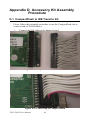
1
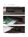
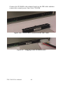
TPC-1261H
GX3 LX800 Touch Panel
Computer with 12.1"
SVGA TFT LCD
User Manual
Copyright
The documentation and the software included with this product are copyrighted 2004 by Advantech Co., Ltd. All rights are reserved. Advantech
Co., Ltd. reserves the right to make improvements in the products
described in this manual at any time without notice. No part of this manual may be reproduced, copied, translated or transmitted in any form or
by any means without the prior written permission of Advantech Co., Ltd.
Information provided in this manual is intended to be accurate and reliable. However, Advantech Co., Ltd. assumes no responsibility for its use,
nor for any infringements of the rights of third parties, which may result
from its use.
Acknowledgements
Intel and Pentium are trademarks of Intel Corporation.
Microsoft Windows and MS-DOS are registered trademarks of
Microsoft Corp.
All other product names or trademarks are properties of their respective
owners.
This Manual Covers the Following Models
• TPC-1261H-A1
• TPC-1261H-A1E
Part No. 2003126120
1st Edition
Printed in Taiwan
May 2006
TPC-1261H User Manual
ii
Product Warranty (1 year)
Advantech warrants to you, the original purchaser, that each of its products will be free from defects in materials and workmanship for one year
from the date of purchase.
This warranty does not apply to any products which have been repaired or
altered by persons other than repair personnel authorized by Advantech,
or which have been subject to misuse, abuse, accident or improper installation. Advantech assumes no liability under the terms of this warranty as
a consequence of such events.
Because of Advantech’s high quality-control standards and rigorous testing, most of our customers never need to use our repair service. If an
Advantech product is defective, it will be repaired or replaced at no
charge during the warranty period. For out-of-warranty repairs, you will
be billed according to the cost of replacement materials, service time and
freight. Please consult your dealer for more details.
If you think you have a defective product, follow these steps:
1.
Collect all the information about the problem encountered. (For
example, CPU speed, Advantech products used, other hardware
and software used, etc.) Note anything abnormal and list any
onscreen messages you get when the problem occurs.
2.
Call your dealer and describe the problem. Please have your manual, product, and any helpful information readily available.
3.
If your product is diagnosed as defective, obtain an RMA (return
merchandize authorization) number from your dealer. This allows
us to process your return more quickly.
4.
Carefully pack the defective product, a fully-completed Repair and
Replacement Order Card and a photocopy proof of purchase date
(such as your sales receipt) in a shippable container. A product
returned without proof of the purchase date is not eligible for warranty service.
5.
Write the RMA number visibly on the outside of the package and
ship it prepaid to your dealer.
iii
CE
This product has passed the CE test for environmental specifications
when shielded cables are used for external wiring. We recommend the
use of shielded cables. This kind of cable is available from Advantech.
Please contact your local supplier for ordering information.
FCC Class A
This equipment has been tested and found to comply with the limits for a
Class A digital device, pursuant to Part 15 of the FCC Rules. These limits
are designed to provide reasonable protection against harmful interference when the equipment is operated in a commercial environment. This
equipment generates, uses and can radiate radio frequency energy and, if
not installed and used in accordance with the instruction manual, may
cause harmful interference to radio communications. Operation of this
equipment in a residential area is likely to cause harmful interference in
which case the user will be required to correct the interference at his own
expense.
Technical Support and Assistance
Step 1. Visit the Advantech web site at www.advantech.com/support
where you can find the latest information about the product.
Step 2. Contact your distributor, sales representative, or Advantech's
customer service center for technical support if you need additional assistance. Please have the following information ready
before you call:
- Product name and serial number
- Description of your peripheral attachments
- Description of your software (operating system, version, application software, etc.)
- A complete description of the problem
- The exact wording of any error messages
TPC-1261H User Manual
iv
Packing List
Before setting up the system, check that the items listed below are
included and in good condition. If any item does not accord with the
table, please contact your dealer immediately.
• 1 x TPC-1261H-A1
• 8 x Panel mounting clampers
• 8 x Panel mounting screws
• 1 x 3-Pin power connector
• 1 x TPC x86 Series support CD
• 1 x CompactFlash to IDE adapter board
Safety Instructions
1.
Read these safety instructions carefully.
2.
Keep this User's Manual for later reference.
3.
Disconnect this equipment from any AC outlet before cleaning.
Use a damp cloth. Do not use liquid or spray detergents for cleaning.
4.
For plug-in equipment, the power outlet socket must be located
near the equipment and must be easily accessible.
5.
Keep this equipment away from humidity.
6.
Put this equipment on a reliable surface during installation. Dropping it or letting it fall may cause damage.
7.
The openings on the enclosure are for air convection. Protect the
equipment from overheating. DO NOT COVER THE OPENINGS.
8.
Make sure the voltage of the power source is correct before connecting the equipment to the power outlet.
9.
Position the power cord so that people cannot step on it. Do not
place anything over the power cord.
10.
All cautions and warnings on the equipment should be noted.
11.
If the equipment is not used for a long time, disconnect it from the
power source to avoid damage by transient overvoltage.
12.
Never pour any liquid into an opening. This may cause fire or electrical shock.
v
13.
Never open the equipment. For safety reasons, the equipment
should be opened only by qualified service personnel.
14.
If one of the following situations arises, get the equipment checked
by service personnel:
a. The power cord or plug is damaged.
b. Liquid has penetrated into the equipment.
c. The equipment has been exposed to moisture.
d. The equipment does not work well, or you cannot get it to work
according to the user's manual.
e. The equipment has been dropped and damaged.
f. The equipment has obvious signs of breakage.
15.
DO NOT LEAVE THIS EQUIPMENT IN AN ENVIRONMENT
WHERE THE STORAGE TEMPERATURE MAY GO BELOW 20° C (-4° F) OR ABOVE 60° C (140° F). THIS COULD DAMAGE THE EQUIPMENT. THE EQUIPMENT SHOULD BE IN A
CONTROLLED ENVIRONMENT.
16.
CAUTION: DANGER OF EXPLOSION IF BATTERY IS
INCORRECTLY REPLACED. REPLACE ONLY WITH THE
SAME OR EQUIVALENT TYPE RECOMMENDED BY THE
MANUFACTURER, DISCARD USED BATTERIES ACCORDING TO THE MANUFACTURER'S INSTRUCTIONS.
The sound pressure level at the operator's position according to IEC 7041:1982 is no more than 70 dB (A).
DISCLAIMER: This set of instructions is given according to IEC 704-1.
Advantech disclaims all responsibility for the accuracy of any statements
contained herein.
TPC-1261H User Manual
vi
Contents
Chapter
Chapter
1 General Information ....................................... 2
1.1
1.2
Introduction ....................................................................... 2
Specifications .................................................................... 3
1.3
1.4
1.5
1.6
LCD Specifications ........................................................... 4
Touchscreen Specifications............................................... 4
Power................................................................................. 5
I/O Ports Arrangement ...................................................... 5
1.7
Panel Mounting ................................................................. 5
1.8
Dimensions and Cutout ..................................................... 6
1.2.1
1.2.2
1.2.3
System Kernel ................................................................ 3
I/O Ports ......................................................................... 3
Safety and Environment ................................................. 3
Figure 1.1:I/O Port Arrangement ................................... 5
Figure 1.2:Panel Mounting ............................................ 6
Figure 1.3:Dimensions ................................................... 7
2 System Setup.................................................. 10
Figure 2.1:Unpack the Package ................................... 10
Figure 2.2:Install CompactFlash Memory Card .......... 11
Figure 2.3:Power Connector and Power Lines ............ 11
Figure 2.4:Power Receptor & Button Pin Assignment 11
Figure 2.5:Touchscreen Icon ....................................... 12
Figure 2.6:Touchscreen Calibration ............................ 12
Chapter
3 System Engine................................................ 14
Table 3.1:Mainboard Connectors & Jumper Settings . 14
Figure 3.1:Main Board Connectors - 1 ........................ 15
Figure 3.2:Main Board Connectors - 2 ........................ 15
Chapter
4 Software Configuration ................................ 18
4.1
VGA Driver Installation.................................................. 18
4.2
Advantech COM Driver Install ....................................... 23
Figure 4.1:Device Manager ......................................... 18
Figure 4.2:Update Driver ............................................. 19
Figure 4.3:Update Wizard-1 ....................................... 19
Figure 4.4:Update Wizard-2 ........................................ 20
Figure 4.5:Update Wizard-3 ....................................... 20
Figure 4.6:Update Wizard-4 ........................................ 21
Figure 4.7:Update Wizard-5 ....................................... 21
Figure 4.8:Update Wizard-6 ........................................ 22
Figure 4.9:Driver Installation Complete ...................... 22
Figure 4.10:PCI_ICOM Setup ..................................... 23
Figure 4.11:PCI ICOM Installation - 1 ....................... 23
Figure 4.12:PCI ICOM Installation - 2 ........................ 24
Figure 4.13:Device Manager Screen ........................... 24
vii
Table of Contents
Figure 4.14:Update Driver - 1 ...................................... 25
Figure 4.15:Update Driver - 2 ...................................... 25
Figure 4.16:Update Driver - 3 ...................................... 26
Figure 4.17:Slave Bridge Installation Complete .......... 26
Figure 4.18:PCI-1602 Device Manager ....................... 27
Figure 4.19:PCI Serial port Device Manager .............. 28
Figure 4.20:Update Driver - 1 ...................................... 28
Figure 4.21:Update Driver - 2 ...................................... 29
Figure 4.22:Update Driver - 3 ...................................... 29
Figure 4.23:PCI-1602 Master Installation ................... 30
Figure 4.24:PCI Serial Port Installation - 1 ................. 30
Figure 4.25:PCI Serial Port Installation - 2 ................ 31
Figure 4.26:PCI Serial Port Installation - 3 ................. 31
Figure 4.27:PCI Serial Port Installation - 4 ................ 32
Figure 4.28:PCI Serial Port Installation - 5 ................. 32
Figure 4.29:PCI Serial Port Installation - 6 ................. 33
Figure 4.30:PCI Serial Port Installation - 7 ................. 33
Figure 4.31:Installation Complete ............................... 34
4.3
Chapter
Entertainment Encryption/Decryption Driver................. 34
Figure 4.32:Device Manager ....................................... 34
Figure 4.33:Install Wizard - 1 ..................................... 35
Figure 4.34:Install Wizard - 2 ...................................... 35
Figure 4.35:Install Wizard - 3 ...................................... 36
Figure 4.36:Driver Installation Complete .................... 36
5 Features in Windows XP Embedded........... 38
5.1
5.2
5.3
EWF ................................................................................ 38
HORM............................................................................. 39
Advantech Utilities.......................................................... 39
5.3.1
5.3.2
5.3.3
Version Information ..................................................... 40
OSLock and OSUnLock .............................................. 40
HORM ......................................................................... 40
Appendix A Serial Port Settings........................................ 44
A.1
A.2
COM1/ COM2/ COM3 Connector Definition ................ 44
COM4 Setting ................................................................. 45
Appendix B Watchdog Timer
Programming..... 48
B.1
B.2
Overview ......................................................................... 48
Watchdog Timer Programming....................................... 49
B.3
Example Programs .......................................................... 51
Figure B.1:Watchdog timer programming procedure .. 49
Table B.1:Watchdog Timer Registers ......................... 50
Appendix C Watchdog Timer Programming on WinCE 58
C.1
C.2
DeviceIOControl ............................................................. 58
C.1.1
Parameters .................................................................... 59
How to Use the Control Code ......................................... 60
C.2.1
TPC-1261H User Manual
IOCTL _WDT_ENABLE: ........................................... 60
viii
C.2.2
C.2.3
C.2.4
C.2.5
C.2.6
C.3
IOCTL _WDT_DISABLE: .......................................... 60
IOCTL_WDT_STROBE: ............................................ 60
IOCTL_WDT_GETTIMEOUT: .................................. 61
IOCTL_WDT_SETTIMEOUT: .................................. 61
IOCTL_WDT_REBOOT: ........................................... 61
Examples ......................................................................... 62
Appendix D Accessory Kit Assembly Procedure ............. 66
D.1
CompactFlash to IDE Transfer Kit ................................. 66
Figure D.1:Adapter Board and IDE Cable ................... 66
Figure D.2:Connecting the Adapter Board .................. 66
Figure D.3:CompactFlash Slot .................................... 67
Figure D.4:Insert the Adapter Board into the CF slot .. 67
Figure D.5:Inserted Adapter Board ............................. 67
Figure D.6:Connect the CD-ROM via the IDE Cable . 68
Figure D.7:Plugging in the CD-ROM Drive ............... 68
Appendix E HDD Kit Assembly........................................ 70
E.1
Ruggedized HDD Kit ...................................................... 70
E.2
Internal HDD Kit Assembly............................................ 77
Figure E.1:Removing the HDD cover ......................... 70
Figure E.2:Required Parts ............................................ 71
Figure E.3:Opening the Top ........................................ 72
Figure E.4:Fastening the bracket ................................. 72
Figure E.5:Connectting the FPC with the HDD .......... 73
Figure E.6:Placing the HDD insulator on the HDD .... 73
Figure E.7:Reverse side of the HDD holder ................ 74
Figure E.8:Fastening the HDD holder ......................... 74
Figure E.9:Mounting the cushions - 1 ......................... 75
Figure E.10:Mounting the cushions - 2 ....................... 75
Figure E.11:Placing the HDD holder - 1 ..................... 76
Figure E.12:Placing the HDD holder - 2 ..................... 76
Figure E.13:Fastening the HDD holder ....................... 77
Figure E.14:Removing the HDD cover ....................... 77
Figure E.15:Placing a screw into its rubber casing ...... 78
Figure E.16:Mounting the rubber casings .................... 78
Figure E.17:Connecting the FPC cable ........................ 79
Figure E.18:Inserting the HDD ................................... 79
Figure E.19:Laying in the HDD insulator ................... 80
Figure E.20:Placing the cover back into position ........ 80
Figure E.21:Re-fastening the cover - 1 ........................ 81
Figure E.22:Re-fastening the cover - 2 ........................ 81
Figure E.23:Fastening the PCI/104 bracket - 1 ............ 82
Figure E.24:Fastening the PCI/104 bracket - 2 ............ 82
Appendix F Touchscreen Installation & Configuration. 84
F.1
Driver Installation ........................................................... 84
Figure F.1:Setup.exe .................................................... 84
ix
Table of Contents
Figure F.2:Install Wizard - 1 ....................................... 84
Figure F.3:Install Wizard - 2 ........................................ 85
Figure F.4:Install Wizard - 3 ........................................ 85
F.2
Uninstall the Driver......................................................... 86
F.3
Touchscreen Calibration ................................................. 87
Figure F.5:Uninstall -1 ................................................. 86
Figure F.6:Uninstall -2 ................................................. 86
Figure F.7:Standard Calibration -1 .............................. 87
Figure F.8:Standard Calibration -2 .............................. 88
Figure F.9:Standard Calibration -3 .............................. 88
Figure F.10:Advanced Calibration -1 ......................... 89
Figure F.11:Advanced Calibration -2 .......................... 90
Figure F.12:Plot Calibration Data ................................ 90
Figure F.13:Draw ........................................................ 91
Figure F.14:Clear Screen ............................................. 92
Figure F.15:Option ...................................................... 93
Appendix G Fuse Specifications ........................................ 96
G.1
G.2
Fuse Specifications.......................................................... 96
Fuse Replacement ........................................................... 96
TPC-1261H User Manual
Figure G.1:Fuse Replacement ...................................... 96
x
CHAPTER
1
2
General Information
This chapter gives background information on TPC-1261H..
Sections include:
• Introduction
• Specifications
• I/O Ports Arrangement
• Panel Mounting
• Exploded Diagrams
• Dimensions & Cutout
Chapter 1 General Information
1.1 Introduction
The TPC-1261H touch panel computer is a state-of-the-art HMI (Human
Machine Interface). This operator interface with a 12.1” display is an
x86-based platform with these key features:
• Fanless
By using a low-power processor, the system does not have to rely on
fans, which often are unreliable and causes dust to circulate inside the
equipment.
• Bright Display
The TFT LCD display suits industrial demands for clear interfaces.
• Powerful Communication Capability
TPC-1261H provides a powerful I/O interface for easily communicating with other devices. The I/O interface includes serial ports, a parallel port, Ethernet and USB 1.1 support. TPC-1261H also supports the
expansion slot PCI/104. This makes it easy to expand with the required
PCI/104 modules.
• Windows CE Support
In addition to the OS support of Windows XP, Advantech offers platform support for Windows CE and Windows XP embedded. The
optional Windows CE operating system specifically for the TPC1261H is available for Windows CE application program builders.
TPC-1261H User Manual
2
1.2 Specifications
1.2.1 System Kernel
• CPU: GeodeLink Control Processor LX800 500MHz
• BIOS: Award 512KB flash memory
• South Bridge: GeodeLink Control Processor CS5535
• VGA: GeodeLink Control Processor LX800 500MHz
• Ethernet: Realtek RTL8100BL; IEEE 802.3u protocol compatible
• Watchdog Timer: W83627 watchdog timer; 1.6 second timeout period
• IDE: 1 EIDE channel supports one CompactFlash socket onboard
(Master) and one IDE interface harddrive (Slave)
1.2.2 I/O Ports
• 1 parallel port: supports EPP/ ECP modes
• 4 serial ports: RS-232 (COM1, COM2, COM3) and RS-232/422/485
(COM4)
• 1 RJ-45 Ethernet port
• 1 PS/2 port: 6-pin mini-DIN ports for keyboard and mouse
• 2 USB 2.0 Ports: compliant with USB 1.0 and 1.1.
• 1 PCI/104 slot
Note:
COM1 and COM2 only support half-duplex
(Maximum baud rate: 115.2Kbps)
1.2.3 Safety and Environment
Safety
• FCC Class A
• CE certificated
• The front bezel is compliant with NEMA 4 and IP65
3
Chapter 1
Environment
• Operating Temperature: 0 ~ 50° C (32 ~ 122° F)
• Storage Temperature: -20 ~ 60° C (-4 ~ 140° F)
• Humidity: 40° C @ 10~95% relative humidity (non-condensing)
• Vibration: 1 grms (5~500Hz)
1.3 LCD Specifications
• Display Type: TFT color LCD
• Size (diagonal): 12.1”
• Maximum Resolution: 800 x 600 (SVGA)
• Maximum Colors: 256,000
• Pixel Pitch (W x H, mm): 0.3075 x 0.3075
• Viewing Angle: 100°
• Luminance (cd/m² ): 340
• Contrast Ratio: 300
• Operating Temperature: 0 ~ 50° C (32 ~ 122° F) (Ambient)
• Backlight: 2 CCFL
• Backlight Life Time: 50,000 hours
Note
There might be several bright or dark pixels on
the LCD. This phenomenon is normal in today’s
LCD manufacturing.
1.4 Touchscreen Specifications
• Touch Type: Resistive
• Base Glass Construction: Tempered Glass
• Resolution: 1024 x 1024
• Light Transmission: 75% typical
• Controller: USB Interface
• Lifespan: 1 million touches at single point
TPC-1261H User Manual
4
1.5 Power
• Input Voltage: 18 - 32VDC (the fuse will become an open circuit if the
input level exceeds 33 VDC)
• Typical: [email protected]
1.6 I/O Ports Arrangement
The arrangement of the I/O ports is shown in Figure 1.1.
Figure 1.1: I/O Port Arrangement
1.7 Panel Mounting
1.
There is an adhesive waterproof gasket on the Mg-AL front bezel.
Make sure the waterproof gasket is in position before installing
TPC-1261H into the panel opening.
2.
Install the TPC-1261H into the panel opening.
3.
Find the eight clampers and eight long screws in the accessory
pack. Hook the clampers to the holes around the four sides of the
bezel. Insert the screws into every clamper and fasten them. These
screws will push the mounting panel and fix the unit.
4.
The suggested mounting panel thickness is less than 6 mm
(0.236”).
5
Chapter 1
Figure 1.2: Panel Mounting
1.8 Dimensions and Cutout
• Weight: 4.1 kg (without HDD)
• Dimensions: 311 x 237 x 58 mm (W x H x D)
• Cutout: 302 x 228 mm (suggested)
TPC-1261H User Manual
6
Figure 1.3: Dimensions
7
Chapter 1
TPC-1261H User Manual
8
CHAPTER
2
2
System Setup
This chapter provides a brief explanation for operating TPC-1261H.
Chapter 2 System Setup
You can easily get TPC-1261H started by following the below steps.
• Step 1: Unpack the TPC-1261H package. Check the packing list at the
beginning of this manual to make sure all items have been included.
Figure 2.1: Unpack the Package
TPC-1261H User Manual
10
• Step 2: Install a CompactFlash card containing Windows CE, embedded Windows XP or another operating system.
Figure 2.2: Install CompactFlash Memory Card
Warning
It is suggested to turn OFF system power as you
plug in or pull out the memory card, even though
the CompactFlash memory is hot swappable.
• Step 3: Connect the power connector to the 24 VDC power lines. The
power lines can either be of some power adapter or in-house power
source.
Figure 2.3: Power Connector and Power Lines
Figure 2.4: Power Receptor & Button Pin Assignment
11
Chapter 2
• Step 4: Plug the power lines into the system power receptor.
• Step 5: Push the power button to power on the system (figure 2.4).
• Step 6: Calibrate the touchscreen (click "PM" in the bottom corner).
Note:
We are using Windows XP as the example.
Please refer appendix F for detail.
Figure 2.5: Touchscreen Icon
Figure 2.6: Touchscreen Calibration
TPC-1261H User Manual
12
CHAPTER
3
2
System Engine
Chapter 3 System Engine
Table 3.1: Mainboard Connectors & Jumper Settings
Label
Function
Description
CN2
LCD POWER
LCD INVERTER Connector
CN3
CF
CompactFlash socket
CN4
IDE
Internal IDE 44pin(2mm) connector
CN5
ETHERNET
RJ45 LAN PORT
CN6
LPT
Printer Port
CN7
COM1
Serial port:COM2 RS232
CN8
COM2
Serial port:COM1 RS232
CN9
DC IN
DC Power in Connector,HOUSING 5.08 MM 3P
CN10
USB2
Two USB Type-A Female to on panel.
CN11
USB1
Two USB Type-A Female to on panel.
CN12
PS2/MOUSE
Standard Mini-DIN 6-pin
CN13
PS2/KEYBOARD
Standard Mini-DIN 6-pin
CN14
PCI104
PCI104 30*4 CONNECTOR
CN15
COM3
Serial port:COM1 RS232
CN16
COM4
Serial port:COM1 RS232/485/422
JP1
PANEL
PANEL CONNECTOR
JP2
TOUCH
TOUCH CONNECTOR
JP4
5V/3V
PCI104 5V/3V SELECT
J1
DDR
DDR CONNECTOR
J3
1*3 PIN HEADER
CLEAR CMOS
SW1
POWER SWITCH
System Power Switch
BH1
BATTERY
RTC BATTERY
FS1
FUSE
FUSE HOLDER
TPC-1261H User Manual
14
Figure 3.1: Main Board Connectors - 1
Figure 3.2: Main Board Connectors - 2
15
Chapter 3
TPC-1261H User Manual
16
CHAPTER
4
2
Software Configuration
Sections include:
• VGA Driver Installation
• Advantech COM Installation
• Entertainment Encryption/
Decryption Driver Installation
Chapter 4 Software Configuration
A support CD-ROM for TPC-1261H is available and along with the
product. There are related utilities and drivers of TPC-1261H for
Windows XP. Please insert the support CD-ROM into your CD-ROM
driver and install the VGA graphics driver, Advantech com driver,
Touchscreen driver and WDM driver sequentially. Touchscreen installation is described in the appendix.
4.1 VGA Driver Installation
Please follow the steps to install VGA driver.
Step 1: Please go to “Device Manager” (control panel -> system -> hardware) and then click “Video Controller”.
Figure 4.1: Device Manager
Step 2: Please go to “Driver” tab to update the driver.
TPC-1261H User Manual
18
Figure 4.2: Update Driver
Step 3: Then follow the update wizard processures.
Figure 4.3: Update Wizard-1
19
Chapter 4
Figure 4.4: Update Wizard-2
Figure 4.5: Update Wizard-3
TPC-1261H User Manual
20
Figure 4.6: Update Wizard-4
Figure 4.7: Update Wizard-5
21
Chapter 4
Figure 4.8: Update Wizard-6
Step 4: After you successfully update the driver, you can see the VGA
successfully installed from the device manager.
Figure 4.9: Driver Installation Complete
TPC-1261H User Manual
22
4.2 Advantech COM Driver Install
Two com ports named COM3 and COM4 on TPC-1261H are Advantech
Special com port. Please follow the steps below to install the driver.
Step 1: Insert the CD-ROM into your CD-ROM drive. Go to the directory: …\TPC-1261H\Driver\Com Port Driver and then excute
PCI_ICOM.exe
Figure 4.10: PCI_ICOM Setup
Step 2: Following the install shield wizard to finish the setup.
Figure 4.11: PCI ICOM Installation - 1
23
Chapter 4
Figure 4.12: PCI ICOM Installation - 2
Step 3: Then, go to “Device Manager” to update the driver. Click “?PCI
Serial Port” and then select “Driver” Tab to update driver as shown in
Figure 4.9
Figure 4.13: Device Manager Screen
TPC-1261H User Manual
24
Figure 4.14: Update Driver - 1
Step 4: Follow the hardware update wizard as the figures below.
Figure 4.15: Update Driver - 2
25
Chapter 4
Figure 4.16: Update Driver - 3
Step 5: Complete the PCI-1602 Series Slave Bridge installation.
Figure 4.17: Slave Bridge Installation Complete
TPC-1261H User Manual
26
Step 6: Then, go to “Device Manager”. You can find “Advantech PCI1602 Series Slave Bridge” is on the list.
Figure 4.18: PCI-1602 Device Manager
Step 7: And then click “? PCI Serial Port” to update the driver.
27
Chapter 4
Figure 4.19: PCI Serial port Device Manager
Figure 4.20: Update Driver - 1
TPC-1261H User Manual
28
Step 8: Follow the hardware update wizard as the figures below.
Figure 4.21: Update Driver - 2
Figure 4.22: Update Driver - 3
29
Chapter 4
Step 9: Complete the Advantech PCI-1602 Series Master Bridge installation.
Figure 4.23: PCI-1602 Master Installation
Step 10: Then, follow the wizard the install the software for Advantech
PCI serial ports as the below.
Figure 4.24: PCI Serial Port Installation - 1
TPC-1261H User Manual
30
Figure 4.25: PCI Serial Port Installation - 2
Figure 4.26: PCI Serial Port Installation - 3
31
Chapter 4
Figure 4.27: PCI Serial Port Installation - 4
Figure 4.28: PCI Serial Port Installation - 5
TPC-1261H User Manual
32
Figure 4.29: PCI Serial Port Installation - 6
Figure 4.30: PCI Serial Port Installation - 7
33
Chapter 4
Step 11: After the steps are done, the software for the com3 and com4 is
successfully installed. Go to “Device Manager” and find the list as
below.
Figure 4.31: Installation Complete
4.3 Entertainment Encryption/Decryption Driver
Step 1: Insert the CD-ROM and go to “Device Manager”. Click “Entertainment Encryption/ Decryption Controller”
Figure 4.32: Device Manager
TPC-1261H User Manual
34
Step 2: Following the install shield wizard to finish the setup.
Figure 4.33: Install Wizard - 1
Figure 4.34: Install Wizard - 2
35
Chapter 4
Figure 4.35: Install Wizard - 3
Step 4: The driver is successfully installed. You can check via “Device
Manager” as the below.
Figure 4.36: Driver Installation Complete
TPC-1261H User Manual
36
CHAPTER
5
2
Features in
Windows XP
Embedded
Sections include:
• EWF
• HORM
• Advantech Utilities
Chapter 5 Features in Windows XP
Embedded
TPC-1261H supports the embedded Windows platform. This section outlines the important features (EWF and HORM), that are provided in Windows XP embedded.
5.1 EWF
EWF stands for Enhanced Write Filter. It provides an upper filter in the
storage device driver stack that redirects disk write operations to volatile
(RAM) or non-volatile (disk) storage. EWF protects a volume from write
access. The benefits are as the following.
Write-protect one or more partitions on your system.
Enable read-only media, such as CD-ROM or flash, to boot and run.
Prolong the lifespan of write-sensitive storage, such as CompactFlash.
TPC-1261H XPE provides EWF RAM RDG mode on system partition.
All wirte to system partition will be redirected to RMA once this mode is
enabled. This mode is manually enabled by customers after they finish
all their changes on system such as installing their applications or adjusting system setting.
Advantech provides a pair of utilities to operate EWF, OSLock and
OSUnLock. The setting is stated in the section later.
TPC-1261H User Manual
38
5.2 HORM
HORM stands for Hibernate Once Resume Many. In HORM environment, a single hibernation file is used to boot the system repeatedly. To
set a HORM environment, please follow the steps below.
Please make sure EWF is disabled. You can run OSUnLock to disable
EWF.
Enable hibernation support:
Run ‘power options’ in control panel, and then select ‘Enable Hibernation’ in hibernation pane.
Enable EWF:
Run OSLock, and then system reboot automatically.
Open those software that customers want to directly use after system
resume from hibernation.
Hibernate via Advantech HORM utility:
Please Click Start Menu->All Programs->Advantech->HORM
HORM environment remains all along unless the following events occur:
Run EWF commit command (ewfmgr c: -commit) and then reboot system.
Select “Discard hibernation file” by clicking F8 when system is starting
up
Also, HORM cannot fit your system if free space in C partition is not
enough. The hibernation file required is dependent on the RAM size you
use on the system. In other words, the hibernation file is 512MB that is
the same as memory size used on TPC-1261H-A1 or TPC-1261H-B1.
5.3 Advantech Utilities
TPC-1261H provides the useful utilities for users to configure the HORM
and EWF.
39
Chapter 5
5.3.1 Version Information
Start menu-> All Programs -> Advantech
This states the current XPE runtime information including hardware platform, version, build number, release date, XPE QFEs installed in component database and XP Pro Patches you installed manually.
5.3.2 OSLock and OSUnLock
The two utilities assist users to enable or disable EWF. Please go to Start
Menu-> All Programs-> Advantech. The default setting of EWF is disabled. Users can protect C partition from any disk writing via OSLock
that is to enable EWF RAM REG Mode. In this mode, any changes on C
partition including modification on files or registry will be redirected to
memory, thus these changes will be discarded in the next system startup.
To exit this environment is via OSUnLock. Please visit MSDN website
for further information about EWF.
5.3.3 HORM
This is to create HORM environment. Please go to Start Menu-> All Programs-> Advantech. This utility firstly dismounts all local physical volumes that are not protected by EWF. It requires users to input the volume
list.
Please follow the steps before running this utility to create full HORM
environment.
Enable Hibernation via Power Options in Control Panel
Make C: partition EWF-enabled via OSLock
Make sure that all volumes to be dismounted are not in use.
TPC-1261H User Manual
40
41
Chapter 5
TPC-1261H User Manual
42
A
APPENDIX
2
Serial Port Settings
Appendix A Serial Port Settings
A.1 COM1/ COM2/ COM3 Connector Definition
1
5
6
Pin
Signal
1
NDCD
2
NRX
3
NTX
4
NDTR
5
GND
6
NDSR
7
NRTS
8
NCTS
9
NRI
Note:
9
COM1 and COM2 only support half-duplex
(Maximum baud rate: 115.2Kbps)
TPC-1261H User Manual
44
A.2 COM4 Setting
The serial port COM4 on the TPC-1570H is adjustable. It can be set to
RS-232, RS-422 or RS-485. This port is designed with auto data flow
control capability. In other word, the TPC-1570H can automatically
detect the data flow direction at this port when the two wired RS-485
communication is activated.
1
6
COM4 Mode
5
9
S1 and S2 setting
RS232 Mode
RS485 Mode
RS422 Master Mode
RS422 Slave Mode
45
Appendix A
PIN
RS-232
RS-422
RS-485
1
NDCD
TX-
D-
2
NRX
TX+
D+
3
NTX
RX+
4
NDTR
RX-
5
GND
GND
6
NDSR
7
NRTS
8
NCTS
9
NRI
TPC-1261H User Manual
46
GND
B
APPENDIX
2
Watchdog Timer
Programming
Appendix B Watchdog Timer
Programming
B.1 Overview
The TPC-1261H watchdog timer can be used to monitor system software
operation and take corrective action if the software fails to function after
the programmed period. This section describes the operation of the
watchdog timer, and how to program it.
The watchdog timer is built into the super I/O controller W83627HF. It
provides the following functions for user programming:
• Can be enabled and disabled by user's program.
• Timer can be set from 1 to 255 seconds or 1 to 255 minutes.
• Generates an interrupt or resets signal if the software fails to reset the
timer after time-out.
TPC-1261H User Manual
48
B.2 Watchdog Timer Programming
The I/O port address of the watchdog timer is 2E(hex) and 2F(hex), 2E
(hex) is the address port. 2F(hex) is the data port. You must first assign
the address of register by writing address value into address port 2E(hex),
then write/read data to/from the assigned register through data port 2F
(hex).
Figure B.1: Watchdog timer programming procedure
49
Chapter B
Table B.1: Watchdog Timer Registers
Address of
register (2E)
Attribute
Description
Read/Write
Value (2F)
and
description
87 (hex)
-----
Write this address to I/O address
port 2E (hex) twice to unlock the
W83627HF
07 (hex)
write
Write 08 (hex) to select register of
watchdog timer.
30 (hex)
write
Write 01 (hex) to enable the function
of the watchdog timer. Disabled is
set as default.
F5 (hex)
write
Set seconds or minutes as units for
the timer.
Write 0 to bit 3: set second as counting unit. [default]
Write 1 to bit 3: set minute as counting unit
F6 (hex)
write
0: stop timer [default]01~FF (hex):
The amount of the count, in seconds
or minutes, depends on the value
set in register F5 (hex). This number
decides how long the watchdog
timer waits for strobe before generating an interrupt or reset signal.
Writing a new value to this register
can reset the timer to count with the
new value.
F7 (hex)
rd/wr
Bit 6: Write 1 to enable keyboard to
reset the timer, 0 to disable.[default]
Bit 5: Write 1 to generate a timeout
signal immediately and automatically return to 0. [default=0] Bit 4:
Read status of watchdog timer, 1
means timer is "time out".
AA (hex)
-----
Write this address to I/O port 2E
(hex) to lock the watchdog timer.2
TPC-1261H User Manual
50
B.3 Example Programs
1. Enable watchdog timer and set 10 sec. as timeout interval
;----------------------------------------------------------Mov dx,2eh ; Unlock W83627HF
Mov al,87h
Out dx,al
Out dx,al
;----------------------------------------------------------Mov al,07h ; Select registers of watchdog timer
Out dx,al
Inc dx
Mov al,08h
Out dx,al
;----------------------------------------------------------Dec dx ; Enable the function of watchdog timer
Mov al,30h
Out dx,al
Inc dx
Mov al,01h
Out dx,al
;----------------------------------------------------------Dec dx ; Set second as counting unit
Mov al,0f5h
Out dx,al
Inc dx
In al,dx
And al,not 08h
Out dx,al
;----------------------------------------------------------Dec dx ; Set timeout interval as 10 seconds and start counting
Mov al,0f6h
51
Chapter B
Out dx,al
Inc dx
Mov al,10
Out dx,al
;----------------------------------------------------------Dec dx ; lock W83627HF
Mov al,0aah
Out dx,al
2. Enable watchdog timer and set 5 minutes as timeout interval
;----------------------------------------------------------Mov dx,2eh ; unlock W83627H
Mov al,87h
Out dx,al
Out dx,al
;----------------------------------------------------------Mov al,07h ; Select registers of watchdog timer
Out dx,al
Inc dx
Mov al,08h
Out dx,al
;----------------------------------------------------------Dec dx ; Enable the function of watchdog timer
Mov al,30h
Out dx,al
Inc dx
Mov al,01h
Out dx,al
;----------------------------------------------------------Dec dx ; Set minute as counting unit
Mov al,0f5h
TPC-1261H User Manual
52
Out dx,al
Inc dx
In al,dx
Or al,08h
Out dx,al
;----------------------------------------------------------Dec dx ; Set timeout interval as 5 minutes and start counting
Mov al,0f6h
Out dx,al
Inc dx
Mov al,5
Out dx,al
;----------------------------------------------------------Dec dx ; lock W83627HF
Mov al,0aah
Out dx,al
3. Enable watchdog timer to be reset by mouse
;----------------------------------------------------------Mov dx,2eh ; unlock W83627H
Mov al,87h
Out dx,al
Out dx,al
;----------------------------------------------------------Mov al,07h ; Select registers of watchdog timer
Out dx,al
Inc dx
Mov al,08h
Out dx,al
;----------------------------------------------------------Dec dx ; Enable the function of watchdog timer
53
Chapter B
Mov al,30h
Out dx,al
Inc dx
Mov al,01h
Out dx,al
;----------------------------------------------------------Dec dx ; Enable watchdog timer to be reset by mouse
Mov al,0f7h
Out dx,al
Inc dx
In al,dx
Or al,80h
Out dx,al
;----------------------------------------------------------Dec dx ; lock W83627HF
Mov al,0aah
Out dx,al
4. Enable watchdog timer to be reset by keyboard
;----------------------------------------------------------Mov dx,2eh ; unlock W83627H
Mov al,87h
Out dx,al
Out dx,al
;----------------------------------------------------------Mov al,07h ; Select registers of watchdog timer
Out dx,al
Inc dx
Mov al,08h
Out dx,al
;----------------------------------------------------------TPC-1261H User Manual
54
Dec dx ; Enable the function of watchdog timer
Mov al,30h
Out dx,al
Inc dx
Mov al,01h
Out dx,al
;----------------------------------------------------------Dec dx ; Enable watchdog timer to be strobed reset by keyboard
Mov al,0f7h
Out dx,al
Inc dx
In al,dx
Or al,40h
Out dx,al
;----------------------------------------------------------Dec dx ; lock W83627HF
Mov al,0aah
Out dx,al
5. Generate a time-out signal without timer counting
;----------------------------------------------------------Mov dx,2eh ; unlock W83627H
Mov al,87h
Out dx,al
Out dx,al
;----------------------------------------------------------Mov al,07h ; Select registers of watchdog timer
Out dx,al
Inc dx
Mov al,08h
Out dx,al
55
Chapter B
;----------------------------------------------------------Dec dx ; Enable the function of watchdog timer
Mov al,30h
Out dx,al
Inc dx
Mov al,01h
Out dx,al
;----------------------------------------------------------Dec dx ; Generate a time-out signal
Mov al,0f7h
Out dx,al ;Write 1 to bit 5 of F7 register
Inc dx
In al,dx
Or al,20h
Out dx,al
;----------------------------------------------------------Dec dx ; lock W83627HF
Mov al,0aah
Out dx,al
TPC-1261H User Manual
56
C
APPENDIX
2
Watchdog Timer
Programming on
WinCE
Appendix C Watchdog Timer Programming on WinCE
There is a built-in watchdog timer in Windows CE 4.2 for TPC-1261H.
You can access it through the WIN32 API. TPC-1261H provides a WDT
driver to allow users to enable/disable the watchdog timer. The driver
name is “WDT1:”. Programmers must open this driver before using the
resources. Then programmers can use DeviceIOControl functions to
enable/disable the watchdog timer. The introduction below includes
DeviceIOControl, the definition of the parameter and an example.
C.1 DeviceIOControl
This function sends a control code directly to a specified device driver,
causing the corresponding device to perform the specified operation.
BOOL DeviceIoControl(
HANDLE hDevice,
DWORD dwIoControlCode,
LPVOID lpInBuffer,
DWORD nInBufferSize,
LPVOID lpOutBuffer,
DWORD nOutBufferSize,
LPDWORD lpBytesReturned,
LPOVERLAPPED lpOverlapped );
TPC-1261H User Manual
58
C.1.1 Parameters
• hDevice
[in] Handle to the device that is to perform the operation. Call the CreateFile function to obtain a device handle.
• dwIoControlCode
[in] Specifies the control code for the operation. This value identifies
the specific operation to be performed and the type of device on which
the operation is to be performed. No specific values are defined for the
dwIoControlCode parameter. However, the writer of a custom device
driver can define IOCTL_XXXX control codes, per the CTL_CODE
macro. These control codes can then be advertised, and an application
can use these control codes with DeviceIoControl to perform driverspecific functions.
• lpInBuffer
[in] Long pointer to a buffer that contains the data required to perform
the operation. This parameter can be NULL if the dwIoControlCode
parameter specifies an operation that does not require input data.
• nInBufferSize
[in] Size, in bytes, of the buffer pointed to by lpInBuffer.
• lpOutBuffer
[out] Long pointer to a buffer that receives the operation.s output data.
This parameter can be NULL if the dwIoControlCode parameter specifies an operation that does not produce output data.
• nOutBufferSize
[in] Size, in bytes, of the buffer pointed to by lpOutBuffer.
• lpBytesReturned
[out] Long pointer to a variable that receives the size, in bytes, of the
data stored into the buffer pointed to by lpOutBuffer. The lpBytesReturned parameter cannot be NULL. Even when an operation produces
no output data, and lpOutBuffer can be NULL, the DeviceIoControl
function makes use of the variable pointed to bylpBytesReturned.
After such an operation, the value of the variable is without meaning.
• lpOverlapped
[in] Ignored; set to NULL.
• Return Values
Nonzero indicates success. Zero indicates failure. To get extended
error information, call GetLastError.
59
Appendix C
C.2 How to Use the Control Code
There are 6 control codes for the operation codes in the WDT driver.
C.2.1 IOCTL _WDT_ENABLE:
Enables the watchdog timer of your application. By default, if the watchdog timer is enabled, the WDT driver will automatically trigger itself
after the specified period and your application does not need to trigger the
watchdog timer.
lpInBuffer: unused.
nInBufferSize: unused.
lpOutBuffer: unused.
nOutBufferSize: unused.
C.2.2 IOCTL _WDT_DISABLE:
Disables the watchdog time of your application.
lpInBuffer : unsed.
nInBufferSize: unused.
lpOutBuffer: unused.
nOutBufferSize: unused.
C.2.3 IOCTL_WDT_STROBE:
Triggers the watchdog. If your application uses IOCTL_WDT_ENABLE
to enable the watchdog first and then sends IOCTL_WDT_REBOOT to
the WDT driver, your application must trigger the watchdog once during
the watchdog timer period. If your application has not triggered at the
specified period, the device will reboot automatically.
lpInBuffer: unused.
nInBufferSize: unused.
lpOutBuffer: unused.
nOutBufferSize: unused.
TPC-1261H User Manual
60
C.2.4 IOCTL_WDT_GETTIMEOUT:
Gets the Watchdog time setting.
lpInBuffer: unused.
nInBufferSize: unused.
lpOutBuffer: The DWORD points to your watchdog time setting. The
Watchdog time setting is just a number. 0 means 2 seconds, 1 means 5
seconds, 2 means 10 seconds, 3 means 15 seconds, 4 means 30 seconds, 5
means 45 seconds and 6 means 60 seconds. The default setting is 5 seconds.
nOutBufferSize: unused.
C.2.5 IOCTL_WDT_SETTIMEOUT:
Sets the watchdog time setting.
lpInBuffer : The DWORD points to your watchdog time setting. The
watchdog time setting is just a number. 0 means 2 seconds, 1 means 5
seconds, 2 means 10 seconds, 3 means 15 seconds, 4 means 30 seconds, 5
means 45 seconds and 6 means 60 seconds. The default setting is 5 seconds.
nInBufferSize:.unused.
lpOutBuffer: unused.
nOutBufferSize: unused.
C.2.6 IOCTL_WDT_REBOOT:
If you want your application to trigger the watchdog by itself, please use
IOCTL_WDT_REBOOT to notify the watchdog driver timer (WDT).
Otherwise, the WDT will trigger itself automatically.
lpInBuffer :unused.
nInBufferSize: unused.
lpOutBuffer: unused.
nOutBufferSize: unused.
61
Appendix C
C.3 Examples
#define WDT_CODE(ID)
CTL_CODE(FILE_DEVICE_UNKNOWN,ID,
METHOD_BUFFERED, FILE_ANY_ACCESS)
#define IOCTL_WDT_ENABLE WDT_CODE (0x900)
#define IOCTL_WDT_DISABLE WDT_CODE(0x901)
#define IOCTL_WDT_STROBE WDT_CODE(0x902)
#define IOCTL_WDT_GET_TIMEOUT WDT_CODE(0x903)
#define IOCTL_WDT_SET_TIMEOUT WDT_CODE(0x904)
#define IOCTL_WDT_REBOOT WDT_CODE(0x905)
// for compatibility reasons, you can define IOCTL as below:
// #define IOCTL_WDT_ENABLE 0x1001
// #define IOCTL_WDT_DISABLE 0x1002
// #define IOCTL_WDT_STROBE 0x1003
// #define IOCTL_WDT_GETTIMEOUT 0x1004
// #define IOCTL_WDT_SETTIMEOUT 0x1005
// #define IOCTL_WDT_REBOOT 0x1006
HANDLE m_hWDT=NULL;
TCHAR szClassName[60];
// assign the WDT driver name
wsprintf(szClassName, TEXT("WDT1:"));
// Open the WDT driver
m_hWDT = CreateFile(szClassName, GENERIC_READ
GENERIC_WRITE, 0, NULL, OPEN_EXISTING,
FILE_ATTRIBUTE_NORMAL, NULL);
if ( m_hWDT == INVALID_HANDLE_VALUE ) {
DebugMsg(CString("WDT driver fail"));
return;
}
DWORD dwTemp;
DWORD nIndex=2;
TPC-1261H User Manual
62
// Set the Watchdog Timer as 10 seconds. Number 2 means 10 seconds.
DeviceIoControl(m_hWDT, IOCTL_WDT_SET_TIMEOUT, &nIndex,
sizeof(nIndex), NULL, 0, &dwTemp, NULL);
// Enable the Watchdog timer
DeviceIoControl(m_hWDT, IOCTL_WDT_ENABLE, NULL, 0, NULL,
0, &dwTemp, NULL);
While (1) {
// do your job here.
Sleep(8000);
DeviceIoControl(m_hWDT, IOCTL_WDT_STROBE, NULL,0,
NULL, 0, &dwTemp, NULL);
}
DeviceIoControl(m_hWDT, IOCTL_WDT_DISABLE, NULL, , NULL,
0, &dwTemp, NULL);
CloseHandle(m_hWDT);
63
Appendix C
TPC-1261H User Manual
64
D
APPENDIX
2
Accessory Kit
Assembly Procedure
This appendix shows how to connect to
a CD-ROM via the CompactFlash slot.:
Appendix D Accessory Kit Assembly
Procedure
D.1 CompactFlash to IDE Transfer Kit
Please follow this assembly procedure to use the CompactFlash slot to
connect with a CD-ROM drive.
1.
Connect the IDE cable to the adapter board.
Figure D.1: Adapter Board and IDE Cable
Figure D.2: Connecting the Adapter Board
TPC-1261H User Manual
66
Note
2.
Pin 1 is marked red
Insert the adapter board into the CompactFlash slot.
Figure D.3: CompactFlash Slot
Figure D.4: Insert the Adapter Board into the CF slot
Figure D.5: Inserted Adapter Board
67
Appendix D
Connect the CD-ROM to the adapter board via the IDE cable and then
connect the external power line to the CD-ROM.
Figure D.6: Connect the CD-ROM via the IDE Cable
Figure D.7: Plugging in the CD-ROM Drive
TPC-1261H User Manual
68
APPENDIX
2
E
HDD Kit Assembly
Appendix E HDD Kit Assembly
TPC-1261H provides two way to assemble the HDD into the system. The
ruggized HDD kit is to resist against the high vibration.
E.1 Ruggedized HDD Kit
Please follow the assembly procedure to install the HDD into the system.
1.
Remove the default HDD cover from the system. The required
parts are shown below.
.
Figure E.1: Removing the HDD cover
TPC-1261H User Manual
70
Figure E.2: Required Parts
71
Appendix E
2.
Place the base bracket on the rear case and carefully pull out the
FPC cable through the hole of the bracket
.
Figure E.3: Opening the Top
3.
Fasten the base on the rear case of the system by 5 screws.
Figure E.4: Fastening the bracket
TPC-1261H User Manual
72
4.
Carefully connect the FPC cable to the HDD and then put the HDD
insultor on the HDD.
Figure E.5: Connectting the FPC with the HDD
Figure E.6: Placing the HDD insulator on the HDD
73
Appendix E
5.
Fasten the HDD holder with the HDD and HDD insulator. Please
turn over the HDD holder and fasten them with 4 screws.
Figure E.7: Reverse side of the HDD holder
Figure E.8: Fastening the HDD holder
TPC-1261H User Manual
74
6.
Mount the HDD cushions with the HDD holder.
Figure E.9: Mounting the cushions - 1
Figure E.10: Mounting the cushions - 2
75
Appendix E
7.
Place the HDD holder on the rear cover of the system and then fasten the holder with the system by four screws. Then, the assembly of
high vibration resistance HDD module is done.
Figure E.11: Placing the HDD holder - 1
Figure E.12: Placing the HDD holder - 2
TPC-1261H User Manual
76
Figure E.13: Fastening the HDD holder
E.2 Internal HDD Kit Assembly
Please follow the steps to assemble the internal HDD kit.
1.
Remove the default HDD cover from the system.
Figure E.14: Removing the HDD cover
77
Appendix E
2.
There are four rubber screw casings, and four screws. Places the
screws into their casings
Figure E.15: Placing a screw into its rubber casing
3.
Mount the rubber HDD cushions on the HDD cover.
Figure E.16: Mounting the rubber casings
TPC-1261H User Manual
78
4.
Connect the FPC cable to the HDD
Figure E.17: Connecting the FPC cable
5.
Put the HDD into the hole of the rear case.
Figure E.18: Inserting the HDD
79
Appendix E
6.
Lay the HDD insulator in right direction.
Figure E.19: Laying in the HDD insulator
7.
Place the default HDD cover on the system.
Figure E.20: Placing the cover back into position
TPC-1261H User Manual
80
8.
Fasten the default HDD cover with the system.
Figure E.21: Re-fastening the cover - 1
Figure E.22: Re-fastening the cover - 2
81
Appendix E
9.
Place the bracket of PCI/104 on the slot and fasten it into place.
Figure E.23: Fastening the PCI/104 bracket - 1
Figure E.24: Fastening the PCI/104 bracket - 2
TPC-1261H User Manual
82
APPENDIX
2
F
Touchscreen
Installation &
Configuration
This appendix demonstrates how to
install the PenMount touchscreen and
set the configuration on TPC-1261H.
This section uses Windows XP as an
example.
Appendix F Touchscreen Installation &
Configuration
F.1 Driver Installation
Please insert the x86 TPC series support CD and go to the driver folder:
(TPC-1261H\Driver\USB touchscreen). Click setup.exe
Figure F.1: Setup.exe
The screen displays the installation wizard for the PenMount USB software. Click “Next”. Follow the installation wizard step by step
.
Figure F.2: Install Wizard - 1
TPC-1261H User Manual
84
Figure F.3: Install Wizard - 2
Figure F.4: Install Wizard - 3
85
Appendix F
F.2 Uninstall the Driver
Please go to Settings and then select Control Panel. Please click Add/
Remove Programs.
Figure F.5: Uninstall -1
Select PenMount USB. Click Remove button. Then, select “Yes” to
remove the PenMountUSB driver and reboot the system
..
Figure F.6: Uninstall -2
TPC-1261H User Manual
86
F.3 Touchscreen Calibration
The “PM”, the icon of the PenMount Control Panel, is in the menu bar
after the touchscreen installation. Please click the icon “PM” to call PenMount Control Panel. It contains six functions: Calibrate, Draw, Option,
and About. About shows the driver version.
Calibrate
Two ways to calibrate the touchscreen include “Standard Calibration” and
“Advanced Calibration”. Standard Calibration is to adjust most touchscreens.
Figure F.7: Standard Calibration -1
87
Appendix F
Figure F.8: Standard Calibration -2
Figure F.9: Standard Calibration -3
TPC-1261H User Manual
88
Note
Touch the red squares in sequence. The calibration is completed after the fifth touch red
point is calibrated. Press “ESC” to skip.
Advanced Calibration is for the aged touchscreens by using 4, 9, 16 or 25
points to calibrate touch panel.
Figure F.10: Advanced Calibration -1
89
Appendix F
Figure F.11: Advanced Calibration -2
Figure F.12: Plot Calibration Data
TPC-1261H User Manual
90
Note
Plot Calibration Data enabled provides the blue
lines to show linearity before calibration and
black lines to show linearity after calibration
when you finished the advanced calibration.
Draw
This is to test the touchscreen operation. Its display shows touch location.
Figure F.13: Draw
Click “menu” and then click “clear screen” to clear the drawing.
91
Appendix F
Figure F.14: Clear Screen
Option
This option is to set the operation mode and beep sounds if the beep
sound is enabled. The operation mode, stream mode and point mode, is
to enable/ disable the mouse’s ability to drag on-screen icons. Stream
mode let the mouse functions as normal and dragging on-screen. Point
mode is only let the mouse a click function. The dragging on-screen is
disabled. Users can turn on / off the beep sound by clicking the “enable
beep sound”.
TPC-1261H User Manual
92
Figure F.15: Option
93
Appendix F
TPC-1261H User Manual
94
G
APPENDIX
2
Fuse Specifications
Appendix G Fuse Specifications
G.1 Fuse Specifications
Rating: 250 V AC, 5 A
Size: 5 x 20 mm
Note
For your protection, the fuse is set to break if
the input voltage exceeds 33 V DC.
G.2 Fuse Replacement
Step 1: Remove the fuse cover
Step 2: Replace the damaged fuse with a new one
Step 3: Place the fuse cover back into position.
Figure G.1: Fuse Replacement
Warning
Do NOT replace the fuse unless it is damaged.
Do NOT replace the fuse with a different rated fuse.
TPC-1261H User Manual
96