1
AT-9900 SERIES
Hardware Reference
AT-9924T
AT-9924SP
AT-9924T/4SP
AT-9900 Series Hardware Reference
Document Number C613-03084-00 REV A.
Copyright © 2004 Allied Telesyn International, Corp. 18900 North Creek
Parkway, Suite 200, Bothell, WA 98011, USA.
All rights reserved. No part of this publication may be reproduced without
prior written permission from Allied Telesyn.
Allied Telesyn International, Corp. reserves the right to make changes in
specifications and other information contained in this document without prior
written notice. The information provided herein is subject to change without
notice. In no event shall Allied Telesyn be liable for any incidental, special,
indirect, or consequential damages whatsoever, including but not limited to
lost profits, arising out of or related to this manual or the information
contained herein, even if Allied Telesyn has been advised of, known, or should
have known, the possibility of such damages.
All trademarks are the property of their respective owners.
Contents
Models Covered By This Reference .................................................................... 3
Why You Should Read This Reference ............................................................... 3
Where To Find More Information ...................................................................... 4
Hardware Description ....................................................................................... 4
Switch Overview ......................................................................................... 4
AT-9900 Series Switch Models .................................................................... 7
Online Documentation ...................................................................................... 9
How to access the CD-ROM and online documentation .............................. 9
How to Use AT-TFTP Server .............................................................................. 10
How to Use Windows Terminal and Windows Hyperterminal .......................... 11
Switch Start-up ............................................................................................... 14
How to log in ........................................................................................... 14
How to access help .................................................................................. 15
Start-up procedures .................................................................................. 15
RS-232 Terminal Port (ASYN0) ......................................................................... 18
Useful Cables .................................................................................................. 19
RS-232 terminal and modem cables ......................................................... 19
Cables for RJ-45 Ethernet LAN interfaces .................................................. 20
Port, Connector, and Cable Combinations ...................................................... 22
LEDs and What They Mean ............................................................................. 23
AT-9900 Series port LEDs .......................................................................... 24
PSU and FOM LEDs ................................................................................... 25
Power Supply Units (PSUs) .............................................................................. 25
Approved PSUs and FOM ......................................................................... 26
Network Processor Accelerator Card ............................................................... 26
What is an accelerator card? .................................................................... 26
Approved network processor accelerator card .......................................... 26
How an accelerator card works ................................................................ 26
How to check if an accelerator card is installed correctly ........................... 27
How to display information about the accelerator card ............................. 28
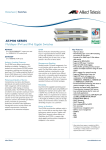
Small Form Factor Pluggable (SFP) Transceivers ................................................ 29
Approved SFP transceivers ........................................................................ 29
SFP port operation .................................................................................... 29
SFP port and RJ-45 port operation ............................................................ 30
How to install and remove a SFP transceiver ............................................. 30
CompactFlash ................................................................................................. 31
Approved CompactFlash cards .................................................................. 31
How to install and remove a CompactFlash card ....................................... 31
How to test a CompactFlash card ............................................................. 32
Dual In-line Memory Modules (DIMMs) ........................................................... 33
Approved DIMM for the AT-9924T and AT-9924SP switches ..................... 33
Approved DIMM for the AT9924T/4SP switch ........................................... 34
How to check if DIMM is installed correctly .............................................. 34
Lithium Battery ............................................................................................... 34
Optional Wall-mount Kit ................................................................................. 35
How to install a switch using the wall-mount kit ....................................... 35
Virtual Cable Test ............................................................................................ 36
How to use the Virtual Cable Test ............................................................. 36
Display Approximate Cable Length .................................................................. 39
Test Facility ..................................................................................................... 39
How to test Ethernet LAN ports ................................................................ 39
Other interface tests ................................................................................. 40
Diagnostics ..................................................................................................... 40
Troubleshooting .............................................................................................. 42
Check these first ...................................................................................... 42
Link/Activity LED on any port is off ........................................................... 42
2
AT-9900 Series Switch
Power LED is off ....................................................................................... 43
Fault LED is on .......................................................................................... 43
Contacting Us ................................................................................................. 44
C613-03084-00 REV A
Hardware Reference
3
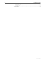
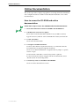
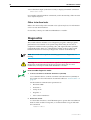
Documentation Roadmap
AT-PWR01
AT-9900 Series
Safety and Statutory Information
AT-9900 Series Safety and Statutory Information Booklet
Quick Install Guide
AT-9900 Series Quick Install Guide
General Customer Support
AT-9900 Series Software Reference
AT-9900 Series Hardware Reference
Printed
Acrobat PDF
Visit www.alliedtelesyn.co.nz for
the latest documentation, FAQs,
and support information.
Website
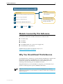
Models Covered By This Reference
This Hardware Reference includes information on these models:
■
AT-9924T/4SP
■
AT-9924T
■
AT-9924SP
■
AT-PWR01 (either AC or DC power supply unit)
■
AT-FAN01 (fan only module)
Find the latest AT-9900 Series Hardware Reference at
http:// www.alliedtelesyn.co.nz/support.
Why You Should Read This Reference
Use this Reference to familiarise yourself with the AT-9900 Series switches and
their hardware features, including the power supply units (PSUs). The
information found in this Reference will assist you with the process of
installing and maintaining your AT-9900 Series switch.
Keep this Reference (or its CD-ROM) in a safe place, you will need it if you
purchase switch expansion options (DIMM) in the future.
Note This Reference does not cover software configuration or software
installation procedures. For information on software, refer to the AT-9900 Series
Software Reference.
C613-03084-00 REV A
4
AT-9900 Series Switch
Where To Find More Information
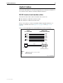
The documentation and tools CD-ROM bundled with each switch contains the
complete document set for AT-9900 Series switches and their power supply
units, as well as tools for switch management.
The documentation and tools CD-ROM includes:
■
The AT-9900 Series Software Reference, which provides detailed information
on configuring the switch and its software.
■
The AT-9900 Series Quick Install Guide, which describes how to install your
switch and includes statutory and safety information.
■
The AT-PWR01 Quick Install Guide, which describes how to install power
supply units and fan only modules in your switch and includes statutory
and safety information.
You can also download these documents from the AT-9900 Series support site
at http:// www.alliedtelesyn.co.nz/support/at9900.
Hardware Description
This section provides an overview of the hardware features of the AT-9900
Series switches.
Switch Overview
AT-9900 Series switches are high density Gigabit Ethernet multi-layer switches,
perfect for the high-density rack environment where space is at a premium.
Dimensions
•
Height = 44.5 mm (plus 5.1 mm if the rubber feet are used)
•
Width = 440 mm (excluding rack-mounting brackets)
•
Depth = 440 mm (excluding PSU handles)
•
Weight = Not more than 8.5 kg (includes single power supply unit and
fan only module)
Mounting system
•
1U rack mounting; 19 inch rack-mount kit as standard
•
Optional wall-mount rack kit
C613-03084-00 REV A
Hardware Reference
5
Environmental conditions
•
Operating temperature range: 0º C to 50º C (32º F to 122º F)
•
Storage temperature range: -25º C to 70º C (-13º F to 158º F)
•
Operating humidity range: 5% to 80% non-condensing
•
Storage humidity range: 5% to 95% non-condensing
•
Operational altitude: 3,050 metres maximum (10,000 feet)
Regulatory standards
•
EMC: EN55022 class A, FCC class A, and VCCI class A. EN61000-3
levels 2 (Harmonics), and 3 (Flicker) (AC models only)
•
Immunity testing to EN55024
•
Safety: UL60950-1, CAN/CSA-C22.2 NO. 60950-1-03, EN60950-1,
AS/NZS60950, EN60825-1
•
Certification: UL, cUL, TUV
LEDs
•
Port, System, and power supply unit status LEDs
•
A complete list of LEDs and their functions is described in “LEDs and
What They Mean” on page 23
Power supply units
•
Power supply units (PSUs) are hot-swappable and load share
•
AC or DC PSU options
Dimensions:
•
Height: 40.9 mm
•
Width: 193 mm
•
Depth: 130 mm
AC models
•
Universal 100/240 VAC 47/63 Hz input
•
Maximum continuous current draw, 2.2 A at 100 V, 1.1 A at 230 V
•
Maximum inrush current (cold start at 25º C/77º F), 70 A at 240 V, 32 A
at 115 V
Important information for service personnel:
CAUTION: double pole/neutral fusing
The rating of fuses FH101 and FH102 is 250 V, 5 A
DC models
C613-03084-00 REV A
•
40 V to 60 V, 48 V nominal
•
Supports either positive grounded or negative grounded operation
•
Maximum continuous current draw, 3.9 A at 40 V
•
Maximum standby current, 100 mA
•
Run/Standby switch
6
AT-9900 Series Switch
Switching core
•
Application-Specific Integrated Circuit (ASIC) switch chip
•
High performance IPv4 switching
•
High performance IPv6 switching (AT-9924T/4SP only)
•
Shared 32 MByte DDR-SDRAM packet buffer
Processing core
•
400 MHz RISC Processor
•
16 MBytes of fixed flash (with provision for an additional 16 MBytes)
•
CompactFlash socket on the front panel for hot swappable expansion of
flash memory up to 128 MBytes
•
512 kBytes of NVSRAM
•
Silicon ID chip storing serial number, board ID, MAC address, and
hardware revision level
AT-9924T and AT-9924SP
•
128 MBytes Synchronous DRAM (expandable to 256 MByte or 512
MByte with DIMM)
AT-9924T/4SP
•
256 MByte Synchronous DRAM (expandable to 512 MByte with DIMM)
•
512 MByte Synchronous DRAM is required if AT-ACC01 network
processor accelerator card fitted
Asynchronous serial port
•
Up to 115 kbps
•
Standard DB9 female RS-232 connector
Network processor accelerator card (AT-9924T/4SP only)
•
Optional network processor accelerator card provides accelerated IPv6
unicast and multicast routing in hardware
•
512 MBytes Synchronous DRAM required, giving 64 K IPv6 static
routes
•
4 K multicast table
•
1000 accelerator hardware filters
C613-03084-00 REV A
Hardware Reference
7
AT-9900 Series Switch Models
This section provides hardware descriptions about individual switch models.
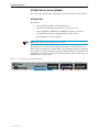
AT-9924T/4SP
Key features:
•
Auto-negotiating Multi-layer Gigabit Switch
•
Optional AT-ACC01 network processor accelerator card
•
24-port 10BASE-T/100BASE-TX/1000BASE-T (RJ-45 connectors)
•
4-port Small Form Factor Pluggable (SFP) uplink sockets
•
Hot-swappable load sharing PSUs
Note Only 24 ports are operational at one time.
The RJ-45 ports 1 to 4 use the same physical interface as the SFP ports 1 to 4.
When a SFP is inserted into a SFP port the corresponding RJ-45 port is disabled.
For example, if a SFP is inserted in SFP port 1 then RJ-45 port 1 is disabled. All
other RJ-45 ports function as normal and when the SFP is removed from port 1
the RJ-45 port 1 is operational.
Figure 1-1: Front panel of the AT-9924T/4SP switch
C613-03084-00 REV A
8
AT-9900 Series Switch
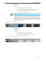
AT-9924T
Key features:
•
Auto-negotiating Multi-layer Gigabit Switch
•
24-port 10BASE-T/100BASE-TX/1000BASE-T (RJ-45 connectors)
•
4-port Small Form Factor Pluggable (SFP) uplink sockets
•
Hot-swappable load sharing PSUs
Note Only 24 ports are operational at one time.
The RJ-45 ports 1 to 4 use the same physical interface as the SFP ports 1 to 4.
When a SFP is inserted into a SFP port the corresponding RJ-45 port is disabled.
For example, if a SFP is inserted in SFP port 1 then RJ-45 port 1 is disabled. All
other RJ-45 ports function as normal and when the SFP is removed from port 1
the RJ-45 port 1 is operational.
Figure 1-2: Front panel of the AT-9924T switch
AT-9924SP
Key features:
•
Auto-negotiating Multi-layer Gigabit Switch
•
24-port Small Form Factor Pluggable (SFP) uplink sockets
•
Hot-swappable load sharing PSUs
Figure 1-3: Front panel of the AT-9924SP switch
C613-03084-00 REV A
Hardware Reference
9
Online Documentation
This section provides a step-by-step guide to accessing online documentation.
Your computer must have Adobe Acrobat Reader installed to view online
documentation.
How to access the CD-ROM and online
documentation
Follow these steps to access the CD-ROM and online documentation:
1.
Insert the Documentation and Tools CD-ROM in the CD-ROM drive.
2.
If the Welcome screen does not appear.
Select "Run" from the Start Menu (Windows 95, 98, 2000 or NT 4.0).
Type d:\start.exe (where d: is the CD-ROM drive letter) and click OK.
3.
To view a document.
Click on the document title.
4.
To navigate around PDF documents.
Use the toolbar buttons, keyboard shortcuts, or commands from the
Document menu to page through the document.
Click on a bookmark, thumbnail or hypertext link to jump to a specific
section or topic.
Use the Search command to search for keywords or phrases.
For more information about using the Adobe Acrobat Reader, select
"Reader Guide" from the Help menu.
5.
To install any of the tools included on the CD-ROM.
Click on a link in the Welcome screen.
C613-03084-00 REV A
10
AT-9900 Series Switch
How to Use AT-TFTP Server
This section provides information on how to access and use AT-TFTP Server.
AT-TFTP Server can be used to transfer configuration files as well as to
download software patches and releases.
To use AT-TFTP Server, follow these steps:
1.
If AT-TFTP Server has not yet been installed.
Install it now from the AT-9900 Series Documentation and Tools CD-ROM.
Choose AT-TFTP Server from the Start > Programs > Allied Telesyn >
AT-TFTP Server menu.
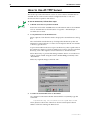
2.
To set preferences for the AT-TFTP Server.
Select "Options" from the File menu to display the "Set Preferences" dialog
box.
The "Default file transfer directory" field specifies the directory that ATTFTP Server will read from or write to for file requests that do not include
a directory specification.
To prevent unauthorised access to private directories, enter a path name in
the "Restrict to directory" field. AT-TFTP Server will use only the specified
directory, even if file requests contain references to other directories.
Select "Read only" to prevent files being written to the PC. To use the PC to
archive scripts created using the switch's create config command, select
"Read Write".
Make any required changes and click "OK".
3.
To load a file from AT-TFTP Server to the Switch.
On a terminal connected to the RS-232 Terminal Port (ASYN0), type the
command:
load method=tftp file=filename server=ipadd dest=flash
where filename is the name of the file to download and ipadd is the IP
address of the PC running AT-TFTP Server.
C613-03084-00 REV A
Hardware Reference
11
4.
To save a TFTP Server log.
Select "Save As" from the File menu.
TFTP requests are logged to the AT-TFTP Server main window.
How to Use Windows Terminal and
Windows Hyperterminal
You can use a PC running terminal emulation software as the manager console,
instead of a terminal. There are many terminal emulation applications
available for PCs, but the most readily available are the Terminal and
HyperTerminal applications included in Microsoft Windows 95, 98, 2000, and
Windows NT 4.0. In standard Windows installations, HyperTerminal is located
in the Start > Programs > Accessories menu.
The key to successful use of terminal emulation software with the switch is to
configure the software and switch with matching communications parameters.
How to configure Windows Terminal and HyperTerminal for the default
RS-232 ASYN0 settings on the switch are described below, but the same
principles apply to other terminal emulation programs.
To configure Windows HyperTerminal for Windows 95, 98, 2000, & NT 4.0.
1.
2.
3.
In Windows, select:
•
Programs > Accessories > HyperTerminal.
•
Double-click the Hypertrm.exe icon.
In the Connection Description dialog box:
•
Enter a name for the connection (e.g., AT99001)
•
Select an icon from the scrolling list.
•
Click “OK”.
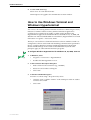
In the Phone Number dialog box:
From the “Connect using:” drop-down list, select:
C613-03084-00 REV A
•
“Direct to Com n” Where “COM n” is the COM port on the PC used to
connect to the switch.
•
Click “OK”.
12
AT-9900 Series Switch
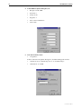
4.
5.
In the COMn Properties dialog box, set:
•
Bits per second: 9600.
•
Data bits: 8.
•
Parity: None.
•
Stop bits: 1.
•
Flow control: Hardware.
•
Click “OK”.
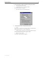
From the File menu, select:
•
“Properties”
In the Connection Properties dialog box, click the Settings tab and set:
•
“Function, arrow, and ctrl keys act as” to “Terminal keys”
•
“Emulation” to VT100.
C613-03084-00 REV A
Hardware Reference
13
6.
Click “ASCII Setup” to display the ASCII Setup dialog box. Uncheck:
•
“Echo typed characters locally”.
•
“Append line feeds to incoming line ends”.
Set other parameters as required.
•
7.
Click “OK” twice to close all dialog boxes.
Save the current session. From the File menu, select:
•
“Save”.
This creates a connection icon with the name you assigned in the
HyperTerminal group. To use the configuration:
•
Double-click the connection icon in the HyperTerminal group.
When the HyperTerminal window appears, press:
•
[Enter] a couple of times.
The switch’s log in prompt will appear.
C613-03084-00 REV A
14
AT-9900 Series Switch
Switch Start-up
This section outlines the log in and start-up procedures for your switch.
Although the switch will perform basic switching operations without being
configured, you will need to go through these log in and start-up procedures if
you wish to configure the switch and access its full switching capabilities.
Before you can log in, the switch’s chassis must have at least one power supply
unit installed and operational, with either a power supply unit or fan only
module installed in the other bay.
How to log in
To log in you must first connect the switch to a terminal or PC. You can do this
via the RS-232 Terminal Port (ASYN0). A terminal cable suitable for use with
ASYN0 is supplied with each switch.
Use the supplied terminal cable, or a cable you have made following the
instructions in “Useful Cables” on page 19, and connect your terminal or PC to
ASYN0 on the switch.
Set the communication parameters on your terminal or terminal emulation
program to:
•
Baud rate: 9600
•
Data bits: 8
•
Parity: None
•
Stop bits: 1
•
Flow control: Hardware
How to configure emulation software is described in “How to Use Windows
Terminal and Windows Hyperterminal” on page 11.
Ensure that any power switches are in the on position and that the switch is
receiving power.
After the switch has booted, the login prompt appears. If the login prompt does
not appear, press [Enter] two or three times.
When the switch boots for the first time it automatically creates an account
with manager privileges. The account has the log in name manager and the
password is friend.
At the log in prompt, enter the log in name and password.
Log in: manager
Password: friend
The switch’s command prompt appears. Now use the Command Line Interface
(CLI) to configure the switch.
Warning Change the password as soon as possible because a manager account
left with the default password is a serious security risk. Remember the new
password as there is no way to retrieve it if it is lost.
C613-03084-00 REV A
Hardware Reference
15
To change the account password, use the command:
set password
How to configure the switch is described in detail in the AT-9900 Series Software
Reference.
How to access help
Before help is used for the first time, you must define the help files. To define
the files, enter:
set help=help-filename
where help-filename is the name of a help file stored in flash.
To see a list of files stored in flash, enter:
show file
Help files have an .hlp extension.
To display a list of help topics, enter:
help
To display help on a specific topic, enter:
help topic
Alternatively, type a question mark (?) at the end of a partially completed
command to see a list of valid options.
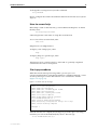
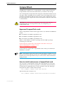
Start-up procedures
When the switch starts up following either a power cycle or an
operator-initiated reboot (using the Reset button or restart command), a series
of start-up messages is sent to the terminal or PC connected to ASYN0
(Figure 1-4 on page 15).
Figure 1-4: Switch start-up messages
INFO:
INFO:
PASS:
INFO:
PASS:
INFO:
INFO:
Force
INFO:
INFO:
INFO:
Self tests beginning.
RAM test beginning.
RAM test, 131072k bytes found.
BBR tests beginning.
BBR test, 512k bytes found.
Self tests complete
Downloading switch software.
EPROM download (Y) ?
Initial download succeeded
Executing configuration script <boot.cfg>
Switch startup complete
Manager >
After the self tests are complete, the manager is given the option of forcing a
mandatory boot from the EPROM (flash) release. The message:
Force EPROM download (Y)?
C613-03084-00 REV A
16
AT-9900 Series Switch
is displayed on the terminal or PC connected to ASYN0 and the switch pauses.
If a key is not pressed within a few seconds, the start-up process will continue
and all steps in the sequence will be executed. Press selected keys on the
terminal immediately after the “Force EPROM download” message is
displayed to change the switch start-up process.
Table 1-1: Switch start-up sequence keystrokes
Pressing key...
Forces the switch to...
[Y]
Load the EPROM release, with no patch.
[S]
Start with the default configuration. Any boot script is ignored.
[Ctrl/D]
Enter diagnostics mode.
During the start-up process the switch will generate four different types of
messages. All messages are preceded by one of the words INFO, PASS, FAIL,
or ERROR. The significance of these words is shown in the table below.
Table 1-2: Switch start-up message classes
Message
Meaning
INFO
An action will be taken by the system.
PASS
A test has been completed successfully.
ERROR
An error message that a test has failed, but the system will continue to
operate.
FAIL
An error message that a fatal error condition has caused the system to
halt in an unrecoverable fashion.
The following table describes start-up messages and their meanings.
Table 1-3: Switch start-up messages and their meanings
Message
Description
INFO: Self tests beginning.
The code loader tests are about to begin.
INFO: RAM test beginning
The RAM tests are about to begin.
PASS: RAM test, 131072k
bytes found
The RAM test passed, and the indicated amount of memory
was found and will be used by the switch.
ERROR: RAM test 5. Error
address = 00345678
A RAM test failed, at the given address. In the example, it
was the fifth test run. The RAM test repeats until it passes,
so a number of messages like this may appear. This fault
means that the memory system is faulty. If the fault
continues, contact your Authorised Allied Telesyn
distributor or reseller immediately.
INFO: BBR tests beginning
The BBR battery tests are about to begin.
PASS: BBR test. Battery OK
The BBR battery tests passed.
ERROR: BBR Battery low
The BBR battery test failed, indicating that the battery is
running low. The BBR battery will need to be replaced.
Contact your Authorised Allied Telesyn distributor or
reseller.
PASS: BBR test, 512k bytes
found
The BBR size/location test passed, with the indicated
amount of BBR found.
C613-03084-00 REV A
Hardware Reference
17
Table 1-3: Switch start-up messages and their meanings (Continued)
Message
Description
FAIL: BBR test. Error address = The BBR size/location test failed at the given location. The
12345678
test at this location failed, indicating the end of memory,
but a valid location was discovered in the 255 long words
following this location. The BBR system will need to be
replaced. Contact your Authorised Allied Telesyn distributor
or reseller.
FAIL: BBR test, only 16k bytes The BBR size/location test completed, but only the displayed
found
amount of memory was found. This amount is less than the
minimum required to run the switch software.
INFO: Self tests complete
The start-up tests have finished.
INFO: Downloading switch
software
The process of downloading the switch software and vector
table from ROM is about to begin.
ERROR: Code load retried
The load of the code from ROM to RAM failed. The load is
retried a number of times. Each time a failure occurs, the
ERROR message is displayed. If the maximum number of
attempts is reached, the FAIL message is displayed.
FAIL: Code load failed
INFO: Initial download
succeeded
The start-up tests and download are complete, and the
switch software is about to be started. If the default install
is a compressed release, the release will now be
decompressed. This may take a few seconds.
The main switch software is about to be loaded into RAM.
INFO: Downloading
compressed release. This may If the release is a compressed release, the release will be
decompressed.
take up to 1 minute...
INFO: Loading software into
memory. This may take up to 1
minute...
INFO: Executing configuration The configuration commands stored in <script-name> are
script <script-name>
being executed. If an error is found in the script, one or
more ERROR messages will be displayed.
INFO: Switch startup complete The start-up process is complete and the switch will now
perform basic switching operations.
Further configuration is necessary if you wish to access the switch’s full
switching capabilities. How to configure the switch is described in detail in the
AT-9900 Series Software Reference.
C613-03084-00 REV A
18
AT-9900 Series Switch
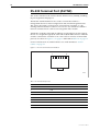
RS-232 Terminal Port (ASYN0)
This section introduces the switch’s RS-232 Terminal Port (ASYN0), including
its pin assignment and purpose.
The RS-232 ASYN0 Terminal Port is used to connect the switch to a
management device for initial configuration and switch management tasks.
This allows the switch’s software to be accessed from a terminal, or a PC
running terminal emulation software. You can also use ASYN0 to establish a
network connection from a remote site using SLIP and a modem.
ASYN0 has an RJ-45 socket with an industry recognised pinout. This requires
the use of a straight-through RJ-45 cable with an RJ-45 DB9 connector when the
switch is connected to a terminal or PC. The socket is wired as a DTE and the
pin roles are shown in Figure 1-5 on page 18 and listed in Table 1-4 on page 18.
For more information on suitable cables to use with ASYN0 see “Useful
Cables” on page 19.
Figure 1-5: RS-232 Terminal Port Pin Numbers
1
8
RJPIN1
Table 1-4: Internal DTE pin roles
Pin
Role
1
RTS
2
DTR1
3
TXD
4
GND
5
GND
6
RXD
7
DSR1
8
CTS
1. DTR and DSR are connected together but have no other internal connection.
C613-03084-00 REV A
Hardware Reference
19
Useful Cables
This section describes how to make management, test, and network cables for
use with the switch’s RS-232 (ASYN0) and RJ-45 interfaces.
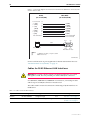
RS-232 terminal and modem cables
The terminal and modem cables described in this section are:
■
RS-232 RJ-45 to DB9 female terminal cable
■
RS-232 RJ-45 to DB9 male modem cable
How to wire cables to connect a standard VT100 compatible terminal, or a
modem, to ASYN0 is shown in Figure 1-6 on page 19 and Figure 1-7 on
page 20.
Figure 1-6: Pin wiring diagram for a standard DB9 male to female terminal cable.
RJ-45
(to switch/DTE)
DE9 Female
(to PC/terminal/DTE)
1
2
3
4
5
6
7
8
9
(DTR) 2
(TXD) 3
(RXD) 6
(DCD) 7
(GND) 5
not connected
(CTS) 8
(RTS) 1
not connected
8
Pin 5
1
(DCD)
(RXD)
(TXD)
(DTR)
(GND)
(DSR)
(RTS)
(CTS)
(RING)
Pin 1
Cable
RJ-45 Pin View
Pin 9
Pin 6
DB9 Female Pin View
Notes:
(1)
(2)
(3)
→ Output from switch; ← Input to switch.
Cable version 1.0.
Pin 4 unconnected.
Ciscowiredrj45db9
C613-03084-00 REV A
20
AT-9900 Series Switch
Figure 1-7: Pin wiring diagram for a DCE RS-232 Terminal Port (DB9 male connector) male
to male modem cable.
RJ-45
(to switch/DTE)
DB9 Male
(to modem/DCE)
4
→ (TXD)
3
← (RXD)
6
← (CD)
7
(GND)
5
→ (DTR)
2
← (CTS)
8
→ (RTS)
1
not connected
not connected
8
3 (TXD)
2 (RXD)
1 (DCD)
5 (GND)
4 (DTR)
8 (CTS)
7 (RTS)
9 not connected
6 not connected
Pin 5
1
Pin 1
Cable
RJ-45 Pin View
Pin 9
Pin 6
DB9 Male Pin View
Notes:
(1)
(2)
→ Output from switch; ← Input to switch
Cable version 1.0.
RJ45DTEDB9Msw
For more information on pin assignments for the RS-232 Terminal Port see
“RS-232 Terminal Port (ASYN0)” on page 18.
Cables for RJ-45 Ethernet LAN interfaces
Warning Do not plug a phone jack into any RJ-45 port because you could
damage the switch. Use only twisted pair cables with RJ-45 connectors.
For 10BASE-T/100BASE-TX/1000BASE-T connections, a twisted pair cable
with four pairs and RJ-45 connectors must be used.
The cables used for network connections and testing of RJ-45 interfaces are
listed below.
Table 1-5: Cables for RJ-45 LAN interfaces
Purpose
Interface type
Cable type
Pairs
Pin assignment
Network
10/100/1000BASE
Straight-through
Four
See Table 1-6 on page 21
Test
10/100/1000BASE
Crossover or straight through
Four
See Table 1-7 on page 22
or Table 1-6 on page 21
C613-03084-00 REV A
Hardware Reference
21
Pin assignments
For twisted pair cables, each pair is identified by two different colours. For
example, one wire might be red, and the other red with a white stripe. A RJ-45
connector must be fitted to both ends of the cable. The pin layout for RJ-45
connectors is illustrated below.
Figure 1-8: RJ-45 Pin layout
8
8
1
1
RJPIN
1000BASE straight-through cable
For 1000BASE network connections, all four pairs are used and the cable is
wired in a straight-through configuration. You can use this cable in conjunction
with the software test facility to test 1000BASE network ports. The pin
assignments are shown in the table below.
Table 1-6: Pin assignments, 10/100/1000BASE-T RJ-45 four pair straight-through cable
End 1
C613-03084-00 REV A
End 2
Pin
Pair
Pin
Pair
1
Pair 1+
1
Pair 1+
2
Pair 1-
2
Pair 1-
3
Pair 2+
3
Pair 2+
6
Pair 2-
6
Pair 2-
4
Pair 3+
4
Pair 3+
5
Pair 3-
5
Pair 3-
7
Pair 4+
7
Pair 4+
8
Pair 4-
8
Pair 4-
22
AT-9900 Series Switch
1000BASE crossover cable
For 1000BASE test cables, all four pairs are used and the cable is wired in either
a crossover or straight-through configuration. Table 1-7 on page 22 lists the pin
assignments for a crossover cable.
Table 1-7: Pin assignments, 10/100/1000BASE-T RJ-45 four pair crossover cable
End 1
End 2
Pin
Pair
Pin
Pair
1
Pair 1+
1
Pair 2+
2
Pair 1-
2
Pair 2-
3
Pair 2+
3
Pair 1+
6
Pair 2-
6
Pair 1-
4
Pair 3+
4
Pair 4+
5
Pair 3-
5
Pair 4-
7
Pair 4+
7
Pair 3+
8
Pair 4-
8
Pair 3-
Port, Connector, and Cable Combinations
The cable guidelines for each switch model are shown below.
Table 1-8: Cable guidelines for AT-9900 Series switches
Model
Port Type
Connector Type
Cable Type1
Maximum Cable Length
AT-9924T/4SP
AT-9924T
10BASE-T
100BASE-TX
1000BASE-T
RJ-45
CAT5
120 m Max
AT-9924T/4SP
AT-9924T
AT-9924SP
1000BASE-X
Varies with SFP
CAT5E
Refer to SFP user
documentation
packaged with SFP
Refer to SFP user
documentation packaged
with SFP
1. Refer to the IEEE 802.3 standards for further cable information.
C613-03084-00 REV A
Hardware Reference
23
LEDs and What They Mean
How the LEDs on AT-9900 Series switches report faults and operational
activities are described are described in Table 1-9 on page 23, Table 1-10 on
page 24, and Table 1-11 on page 24.
How the LEDs on power supply units (AT-PWR01) and fan only modules
(AT-FAN01) report faults and operational activities are described in Table 1-12
on page 25.
System LEDs
Table 1-9: System LEDs on all AT-9900 Series switches
LED
State
Function
PSU 1
Green
PSU 1 is installed and supplying power to the
switch, and the voltage output is within
specification.
Red
PSU 1 is installed in the switch and either a fan
has failed, or the PSU has exceeded its
recommend temperature threshold of 75º C
(167º F).
A FOM is installed in the switch and a fan has
failed.
The bay is empty.
PSU 2
Not lit
A FOM is installed and the fan is good.
Green
PSU 2 is installed and supplying power to the
switch, and the voltage output is within
specification.
Red
PSU 2 is installed in the switch and either a fan
has failed, or the PSU has exceeded its
recommend temperature threshold of 75º C
(167º F).
A FOM is installed in the switch and a fan has
failed.
The bay is empty.
Not lit
C613-03084-00 REV A
A FOM is installed and the fan is good.
24
AT-9900 Series Switch
Table 1-9: System LEDs on all AT-9900 Series switches (Continued)
LED
State
Function
Fault
Red
The switch or management software is
malfunctioning.
1 Flash
One or more heatsink fans has failed or is
operating below the recommended speed.
6 Flashes 1
The switch’s temperature has exceeded the
recommended threshold.
Slow flashing at
startup
The SDRAM (DIMM) has not been detected.
Rapid flashing at
startup
The SDRAM (DIMM) is not compatible with the
switch.
Green
The CompactFlash memory is active. Do not
eject the flash memory module.
CF
1. If the switch exceeds the temperature alarm threshold the fault LED will flash six times, turn off for
a short period, and then repeat the flashing sequence.
AT-9900 Series port LEDs
Table 1-10: SFP Port LEDs on all AT-9900 Series switches
LED
State
Function
L/A
Green
A SFP transceiver is installed and a link is open.
Flashing green
A SFP transceiver is installed and link activity is
occurring.
Amber
A SFP transceiver is installed but a link is not
open.
Flashing amber
A SFP transceiver is installed but there is a
transmission fault.
(Link activity)
Table 1-11: Ethernet Port LEDs on all AT-9900 Series Switches
LED
State
Function
L/A
Green
A 1000 Mbps link is open.
Flashing green
1000 Mbps activity is occurring.
Amber
A 10/100 Mbps link is open.
Flashing amber
10/100 Mbps activity is occurring..
Green
The port is operating in full duplex mode.
Amber
The port is operating in half duplex mode.
Flashing amber
Collisions are occurring.
(Link activity)
D/C
(Duplex/collision)
C613-03084-00 REV A
Hardware Reference
25
PSU and FOM LEDs
Table 1-12: LEDs on the AT-PWR01 and AT-FAN01
LED
State
Function
Fault
Red
There is either a fan failure, or the temperature
has exceeded the limit of 70º C (158º F).
PWR
Green
A PSU is installed in the switch and is receiving
power. The FOM does not have this LED.
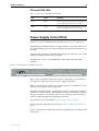
Power Supply Units (PSUs)
At the rear of the AT-9900 Series switch chassis are two power supply bays.
AT9924T and AT-9924SP switches are supplied with a single PSU, either AC or
DC, and a blanking panel covering one PSU bay pre-installed at the factory as
standard.
AT-9924T/4SP switches are supplied with a single PSU, either AC or DC, and a
FOM pre-installed at the factory as standard.
The figure below shows an AT-9900 Series switch with a PSU and FOM
installed.
Figure 1-9: Rear panel of the AT-9900 Series switch
PWR
GOOD FAULT
FAULT
AT-PWR01
AT-FAN01
AC INPUT
100-240V
50/60Hz
3.0A
CAUTION: DISCONNECT POWER CORD PRIOR TO REMOVAL OF PSU
CAUTION: DISCONNECT ALL POWER CORDS TO DISABLE SYSTEM POWER
PSUs are hot-swappable and when two PSU are fitted they will load share. If
you install two PSUs this allows for power supply redundancy.
Both AC and DC power supplies are available. However, combinations of AC
and DC power supplies are not supported.
Each PSU and FOM contains an EPROM allowing for command line interface
identification of the modules. The EPROM will contain information including
the type of module, serial number and revision of the PSU. This information
will be available through the command line interface.
PSU specifications are described in “Power supply units” on page 5.
LEDS on the PSU and FOM are described in“LEDs and What They Mean” on
page 23.
How to install a PSU or FOM in the switch is described in the AT-PWR01 Quick
Install Guide.
C613-03084-00 REV A
26
AT-9900 Series Switch
Approved PSUs and FOM
The part numbers for the PSUs and the FOM that can be fitted in AT-9900
Series switches are:
■
AT-PWR01 (either AC or DC power supply unit)
■
AT-FAN01 (fan only module)
To order additional power supply units, contact your authorised authorised
distributor or reseller for more information, or visit
http:// www.alliedtelesyn.co.nz/support.
Network Processor Accelerator Card
Warning Only authorised service personnel should install a network processor
accelerator card. Unauthorised opening of the switch’s lid may cause danger of
injury from electric shock, cause damage to the switch, and will invalidate the
product warranty.
What is an accelerator card?
The network processor accelerator card is an optional plug-in card for the
AT-9924T/4SP switch that provides accelerated IPv6 unicast and multicast
routing in hardware.
Approved network processor accelerator card
The part number for the accelerator card approved for use with the AT-9900
Series switch is:
■
AT-ACC01 network processor accelerator card
Note For full functionality of the network processor accelerator card 512MB
SDRAM must be installed in the switch.
How an accelerator card works
The AT-ACC01 network processor accelerator card provides acceleration of
routed IPv6 unicast and multicast packets. When the switch receives an IPv6
packet to route, the packet is sent to the accelerator card. The packet is then
processed by the accelerator card and sent out the correct port, with
appropriate alterations to the packet. Other IPv6 functions are passed on to
software, such as routing protocol control packets, encryption, authentication,
and Hop-by-Hop headers.
You do not need to configure the accelerator card for the card to function. The
accelerator card is enabled at installation.
You can disable the accelerator card and the switch then performs IPv6 routing
in software.
C613-03084-00 REV A
Hardware Reference
27
To enable Quality of Service (QoS) functionality on the accelerator card use the
hardware filter and the QoS commands. Detailed information about QoS
functionality and hardware filters is in the Quality of Service (QoS) and
Switching chapters of the AT-9900 Series Software Reference.
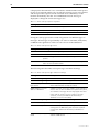
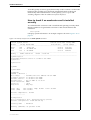
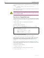
How to check if an accelerator card is installed
correctly
To confirm that the accelerator card is installed and operating correctly check
that the switch has recognised the card. Turn on the switch and enter the
command:
show system
to display system information. An example output is shown in Figure 1-10 on
page 27.
Figure 1-10: Example output from the show system command
Switch System Status
Time 09:35:29 Date 18-Aug-2004.
Board
ID Bay Board Name
Host Id Rev
Serial number
-------------------------------------------------------------------------------Base
220
9924T/4SP
0 P2-0
61117541
PSU
212
1 AT-PWR01-AC
0 P3-0
58494950
PSU
214
2 AT-FAN01
0 P3-0
6844346
-------------------------------------------------------------------------------Memory DRAM :262144 kB
FLASH : 16384 kB
-------------------------------------------------------------------------------SysDescription
CentreCOM 9924T/4SP version 2.7.0-00 13-Jul-2004
SysContact
SysLocation
SysName
SysDistName
SysUpTime
265270 ( 00:44:12
Boot Image
:
Software Version:
Release Version :
Release built
:
Patch Installed :
Territory
:
Help File
:
PSU1: (AC)
PSU2: (FAN)
)
at9924bt.fbr size 1005336 10-Jul-2004
2.7.0-00 13-Jul-2004
2.7.0-00 13-Jul-2004
Aug 15 2004 at 15:32:47
NONE
japan
help.hlp
Fan: Normal
Fan: Normal
Temp: Normal
Power: Normal
Current temperature : Normal
----------------Configuration
Boot configuration file: flash:swload.cfg (exists)
Current configuration: flash:swload.cfg
Security Mode
: Disabled
Warning (2048284): No patches found.
C613-03084-00 REV A
28
AT-9900 Series Switch
The first section of the output shows details of the boards installed in the
switch. There should details of the switch base card, the accelerator card if
installed, and the type of power supply unit or fan only module installed. Both
the part names and the serial numbers of the base card and accelerator card
should be displayed.
If there is no entry for the accelerator card then the switch’s boot process has
not correctly detected the accelerator card’s presence. The most likely cause is
that the accelerator card is not correctly plugged into the slot on the switch’s
base board.
Contact your authorised Allied Telesyn distributor or reseller if an accelerator
card is installed in your switch but the correct details are not displayed in the
output of the show system command.
Record the details of both the base card on the switch and the network
processor accelerator card for later reference. If you have any difficulty with
the network processor accelerator card at any time, contact your authorised
distributor or reseller and quote the serial numbers of both the base card on the
switch and the network processor accelerator card.
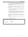
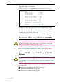
How to display information about the accelerator
card
To display information about the accelerator card’s status and memory, use the
command:
show switch accelerator
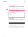
Figure 1-11: Example output from the show switch accelerator command
Switch Accelerator Configuration
--------------------------------------------------------------------------Hardware Type .............. AT-ACC01
Mode ....................... IPv6 Acceleration
Status ..................... IPv6 active
Search memory size ......... 128 Mb
Counter memory size ........ 2 Mb
---------------------------------------------------------------------------
C613-03084-00 REV A
Hardware Reference
29
Small Form Factor Pluggable (SFP)
Transceivers
AT-9900 Series switches have 1000BASE-X Small Form Factor Pluggable (SFP)
uplink sockets on their front panel. The AT-9924T/4SP and AT-9924T have four
SFP sockets and the AT-9924SP has 24 SFP sockets.
Certain fibre and copper SFP transceivers are supported. This allows you to
interchange port types to meet changing network requirements. SFP
transceivers are hot swappable.
Approved SFP transceivers
A range of SFP transceivers have been tested and approved for use with the
AT-9900 Series Switches. You can purchase SFP transceivers when you
purchase a switch, or order them separately as needed.
These SFP transceivers have been approved for use with AT-9900 Series
switches:
■
AT-MG8T 100m Base-T SFP
■
AT-MG8SX 550m SX SFP
■
AT-MG8LX10 10km LX SFP
■
AT-MGZX 70km ZX SFP
For the latest list of approved SFP transceivers either contact your authorised
distributor or reseller, or visit
http:// www.alliedtelesyn.co.nz/support.
SFP port operation
How a Small Form Factor Pluggable (SFP) port operates depends on the type of
SFP transceiver installed in the port.
For a SFP port with an approved fibre SFP transceiver installed, the speed and
duplex setting is fixed at 1000Mbps full duplex autonegotiation.
For a SFP port with an approved copper SFP transceiver installed, the available
speed and duplex settings are:
■
10Mbps and 100Mbps half duplex
■
10Mbps and 100Mbps half duplex autonegotiation
■
10Mbps and 100Mbps full duplex
■
10Mbps and 100Mbps full duplex autonegotiation
■
1000Mbps full duplex autonegotiation
An error message is displayed if a SFP port cannot operate at the specified
speed or duplex mode.
C613-03084-00 REV A
30
AT-9900 Series Switch
SFP port and RJ-45 port operation
On AT-9924T/4SP and AT-9924T switches, 24 ports are operational at one time
out of a total of four SFP ports and 24 RJ-45 ports.
The RJ-45 ports 1 to 4 use the same physical interface as the SFP ports 1 to 4.
When a SFP is inserted, the corresponding RJ-45 port is disabled. For example,
if a SFP is inserted in SFP port 1 then RJ-45 port 1 is disabled. All other RJ-45
ports function as normal and when the SFP is removed from port 1 the RJ-45
port 1 is operational.
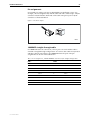
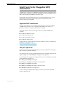
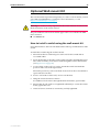
How to install and remove a SFP transceiver
Warning Do not look into SFP cables or transceivers. Invisible laser radiation
may be emitted from disconnected fibres or connectors.
To install a SFP transceiver:
■
Ensure the SFP transceiver is the correct way up, with the delatch button to
the bottom (Figure 1-12 on page 30)
■
Slide the SFP transceiver into the SFP socket
■
Press the SFP transceiver firmly into place
To remove a SFP transceiver:
■
Pull the button at the bottom of the SFP transceiver in to delatch the SFP
transceiver
■
Pull the SFP transceiver gently out of the SFP socket
Figure 1-12: SFP transceiver
SFP transceiver
SFP uplink sockets
Delatch button
SFP1
C613-03084-00 REV A
Hardware Reference
31
CompactFlash
AT-9900 Series switches have a CompactFlash™ socket on their front panel.
CompactFlash cards increase the flash memory available for file storage.
You can manipulate compact flash files using the command line interface (CLI).
Any type of data, including releases, patches, GUIs and configurations can be
stored on CompactFlash cards. However, release, patch, and GUI files cannot
be run directly from compact flash. These files must be loaded into either NVS
or onboard flash.
Warning Data contained on CompactFlash cards can be read with any
compliant reader. Do not keep sensitive data, for example keys, on
CompactFlash cards.
Approved CompactFlash cards
These CompactFlash cards have been approved for use with the AT-9900 Series
switch:
■
AT-CF032A-nnn 32MB CompactFlash card
■
AT-CF064A-nnn 64MB CompactFlash card
■
AT-CF128A-nnn 128MB CompactFlash card
Where n is the number of cards in a package, less than 1000. A package
containing one card is 001.
For the latest list of approved CompactFlash cards either contact your
authorised distributor or reseller, or visit
http:// www.alliedtelesyn.co.nz/support.
For the latest list of approved CompactFlash cards contact your authorised
distributor or reseller.
Note CompactFlash cards used on the switch must support a hardware access
time of no more than 100 nanoseconds. If a CompactFlash card does not meet
the 100 nanosecond requirement it may not work as this is the maximum bus
timing allowed.
How to install and remove a CompactFlash card
You can insert a CompactFlash card into the CompactFlash slot at any time.
Approximately two seconds are required for an inserted card to be initialise.
CLI messages are displayed when a card is inserted or removed. Messages
notify the user when a card has been inserted:
Info (1106257): Compact flash card inserted.
and when the card is ready for use:
Info (1106268): Compact flash card initialisation successful.
C613-03084-00 REV A
32
AT-9900 Series Switch
A message notifies the user if the CompactFlash card is not compatible with the
switch:
Info (3106300): Compact flash card initialisation
unsuccessful.
When compact flash is in use, the CF (compact flash activity) LED on the front
panel of the switch is green.
Warning Do not remove the CompactFlash card when the card is being written
to (that is, when the CF (compact flash activity) LED is lit). Doing so will corrupt
data on the file being written.
How to test a CompactFlash card
To display information about the basic state of a CompactFlash card, including
card size, file count and serial number, insert the card and enter the command:
show cflash
To display cluster ranges on a card, insert the card and enter:
show cflash test
An example output is shown below.
Figure 1-13: Output from the show cflash test command, when no test is running
Clusters available for testing
Ranges:
[42645--61944]
Number of free clusters
Number of ranges
Number of used clusters
= 19300
= 1
= 42645
To test a card, insert the card and enter:
enable cflash test start=startnumber end=endnumber
where startnumber and endnumber are positive integers within a cluster range.
The endnumber must be higher than the startnumber. Cluster ranges are
displayed in the output of the show cflash test command (Figure 1-13 on
page 32).
The test software will read the file allocation table and display a list of free
sectors. Sectors can be tested as single sectors or as a range. The test will consist
of a write/read/verify cycle.
To stop the test, use the command:
disable cflash test
To display the testing process while a test is in process, enter:
show cflash test
C613-03084-00 REV A
Hardware Reference
33
An example output is shown below.
Figure 1-14: Output from the show cflash test command, when a test is running
Test Progress
Starting cluster
Ending cluster
Current cluster
Passed clusters number
Passed sectors number
= 700
= 1700
= 1185
= 485
= 1940
Failed clusters number = 0
Failed sectors number
= 0
Used Clusters encountered = 0
Duration................
4417 ms
If used when testing is not active, the previous command displays blank
cluster ranges on a CompactFlash card (Figure 1-13 on page 32).
Error messages are displayed when a file write fails. Failure could be due to the
card being removed or an error in the card.
Dual In-line Memory Modules (DIMMs)
Warning Only authorised service personnel should install DIMM.
Unauthorised opening of the switch’s lid may cause danger of injury from
electric shock and may cause damage to the switch.
Synchronous DRAM for AT-9900 Series switches is provided by a single
DIMM.
Approved DIMM for the AT-9924T and AT-9924SP
switches
Warning Only Allied Telesyn supplied DIMMS have been tested and approved
for use with AT-9900 Series switches. If you use DIMM that has not been
approved this may cause unreliable operation and will invalidate the switch’s
warranty.
For AT-9924T or AT-9924SP switches, the following DIMM have been
approved for use:
C613-03084-00 REV A
■
AT-SD128A-00 128MB SDRAM (installed at factory)
■
AT-SD256A-00 256MB SDRAM (upgrade)
■
AT-SD512A-00 512MB SDRAM (upgrade)
34
AT-9900 Series Switch
Approved DIMM for the AT9924T/4SP switch
For an AT-9924T/4SP switch without an AT-ACC01 network processor
accelerator card installed, the following DIMM have been approved for use:
■
AT-SD256A-00 256MB SDRAM (installed at factory)
■
AT-SD512A-00 512MB SDRAM (upgrade)
For an AT-9924T/4SP switch with an AT-ACC01 network processor accelerator
card installed, the following DIMM is required:
■
AT-SD512A-00 512MB SDRAM (installed at the factory if the switch is
ordered with an AT-ACC01 fitted)
How to check if DIMM is installed correctly
The switch is unlikely to boot unless the DIMM is correctly installed. If the
switch does boot but you suspect the DIMM is malfunctioning, enter the
command:
show system
to display system information. An example output is shown in Figure 1-10 on
page 27.
In the memory section of the output there should be an entry that shows the
size of DRAM. If the DRAM size is less than the size of DIMM that has been
installed, then the switch has not correctly detected the DIMM. The most likely
cause is that the DIMM connector is not plugged into its slot correctly.
Contact your authorised distributor or reseller if the correct details are not
displayed in the output of the show system command.
Record the switch’s serial number and revision details for future reference. If
you have any difficulty with the DIMM at any time, contact your authorised
distributor or reseller and quote the serial number of the base card on the
switch.
Lithium Battery
Warning Only authorised service personnel should change the lithium battery.
Unauthorised opening of the switch’s lid may cause danger of injury from
electric shock, cause damage to the switch, and will invalidate the product
warranty.
There is a danger of explosion if the lithium battery incorrectly replaced
C613-03084-00 REV A
Hardware Reference
35
Optional Wall-mount Kit
The wall-mount kit is purchased separately. To order a wall-mount kit, contact
your authorised distributor or reseller for more information, or visit
http:// www.alliedtelesyn.co.nz/support.
Warning For electrical safety requirements the switch must be mounted with
the front and rear of the switch vertical.
The part number for the wall-mount kit approved for use with the AT-9900
Series switch is:
■
AT-WBRKT-00
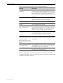
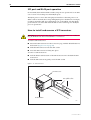
How to install a switch using the wall-mount kit
Screw the brackets to the wall with the brackets at the top and the bottom of the
switch.
To install the switch using the wall-mount kit:
1.
Ensure that there is sufficient space on the wall for the switch and its
associated cables.
2.
Screw the brackets to the sides of the switch using the supplied M4 screws.
The switch is held by wall anchors fixed through the slots in the brackets
(see Figure 1-15 on page 36).
3.
Locate where on the wall you want to mount the switch and mark the
position of the slots in the top brackets.
Ensure the positions you have marked on the wall are the correct distance
apart and are horizontal.
4.
Fix two wall anchors in the wall, one for each bracket.
5.
Hang the switch from these anchors.
Fix additional wall anchors through the bottom brackets, 2 per bracket.
C613-03084-00 REV A
6.
Ensure that all wall anchors are tightened sufficiently to secure the switch
firmly against the wall.
7.
Check all screws and nuts to ensure they are fully tightened.
36
AT-9900 Series Switch
Figure 1-15: Fitting wall-mount brackets on the switch
B
A
A
Bracket
A
B
A
Switch
Key:
A
B
screw
wall anchor slot
9900WM
Virtual Cable Test
Use the Virtual Cable Test facility to diagnose the type of cable fault and the
approximate distance to a cable fault. The Virtual Cable Test facility tests all
four pairs of wires inside the cable and is supported on Gigabit Ethernet RJ-45
ports.
The AT9924T and AT9924T/4SP switches support this feature.
How to use the Virtual Cable Test
To locate cable faults for a specific port or all ports on the switch, use the
command:
enable test cable [port={port-number|all}]
If the test is not finished in 10 seconds then the test is halted and an error
message is displayed.
Warning After the enable test cable command is entered do not connect or
disconnect the cable of the port under test. The RJ-45 ports 1 to 4 use the same
physical interface as the SFP ports 1 to 4. If the RJ-45 port under test is ports 1 to
4, do not insert a SFP into a SFP port that corresponds to this port. When a SFP
is inserted the corresponding RJ-45 port is disabled.
C613-03084-00 REV A
Hardware Reference
37
To display the cable test results for a specified port or all ports, use the
command:
show test cable [port={port-number|all}]
Cable test results are reported for all four pairs of cable and are shown in
“state(length)” format. Possible state values are:
■
no test
■
testing
■
failed
■
good
■
short
■
open
When the state is "open" or "short" the length shown is the approximate
distance to a fault. The accuracy of the distance to the "open" or "short" location
is plus or minus two meters.
When the state is "good" the length shown indicates the approximate length of
the specified pair of cables. The actual value depends on such factors as the
attenuation of the cable, output levels of the remote transceiver, and connector
impedance. The accuracy is plus or minus 10 meters.
Note that “good” cable length, i.e “good(length)”, is reported for ports
operating at 1000Mbps. For ports operating at 10Mbps and 100Mbps, “good” is
reported.
Good cable length is only reported after the gigabit link is established.
An example of the output displayed by a show test cable command is shown
below.
C613-03084-00 REV A
38
AT-9900 Series Switch
Table 1-13: Example output from the show test cable command
Port
Pair 1-2
Pair 3-6
Pair 5-4
Pair 7-8
-----------------------------------------------------------------------------1
no test
no test
no test
no test
2
open(0m)
open(0m)
open(0m)
open(0m)
3
short(1m)
good
good
good
4
open(0m)
open(0m)
open(0m)
open(0m)
5
open(40m)
open(40m)
open(39m)
open(40m)
6
good
open(10m)
good
good
7
good
good
short(81m)
short(82m)
8
open(0m)
open(0m)
open(0m)
open(0m)
9
good(4m)
good(4m)
good(2m)
good(2m)
10
good
good
good
good
11
open(0m)
open(0m)
open(0m)
open(0m)
12
open(0m)
open(0m)
open(0m)
open(0m)
13
good(122m)
good(123m)
good(120m)
good(126m)
14
open(0m)
open(0m)
open(0m)
open(0m)
15
open(0m)
open(0m)
open(0m)
open(0m)
16
open(0m)
open(0m)
open(0m)
open(0m)
17
open(0m)
open(0m)
open(0m)
open(0m)
18
open(0m)
open(0m)
open(0m)
open(0m)
19
open(0m)
open(0m)
open(0m)
open(0m)
20
open(0m)
open(0m)
open(0m)
open(0m)
21
open(0m)
open(0m)
open(0m)
open(0m)
22
open(0m)
open(0m)
open(0m)
open(0m)
23
open(0m)
open(0m)
open(0m)
open(0m)
24
open(0m)
open(0m)
open(0m)
open(0m)
------------------------------------------------------------------------------
To halt the current active cable test, use the command:
disable test cable
To clear all previous cable test results ready to start a new cable test, use the
command:
reset test cable
C613-03084-00 REV A
Hardware Reference
39
Display Approximate Cable Length
To display the approximate cable length used by Gigabit Ethernet RJ-45 ports,
use the command:
show switch port
The AT9924T and AT9924T/4SP switches support this feature.
For the port or ports specified, the Cable Length parameter displays the
approximate cable length used by the port in meters. Possible Cable Length
parameter values are:
■
<50m
■
50-80m
■
80-110m
■
110-140m
■
>140m
■
- (either the port link is down, or the port is operating at either 10Mbps or
100Mbps)
Cable Length is only reported for Gigabit Ethernet RJ-45 ports after the link is
established.
Test Facility
This section introduces the Test Facility. The Test Facility is built into all
AT-9900 Series software. How to operate the Test Facility is described in detail
in the Test Facility chapter of the AT-9900 Series Software Reference.
Any interfaces under test are dedicated to the Test Facility. Think of the Test
Facility as a specialised interface module like PPP or Frame Relay.
Note Before you use the Test Facility, disable any configurations with the
command set configuration=none and restart or reboot the switch.
How to test Ethernet LAN ports
A crossover cable is required to run an Ethernet LAN test. How to make a
suitable cable is described in “Useful Cables” on page 19. To start the test, loop
a four-pair crossover or straight-through cable between any two RJ-45 ports
and enter:
enable test int=all
All interfaces connected by crossover cables are tested. Test results are
displayed with the command:
show test
C613-03084-00 REV A
40
AT-9900 Series Switch
A more detailed output (with frame counts) is displayed with the command:
show test count
For example output from these commands, see the Test Facility of the AT-9900
Series Software Reference.
Other interface tests
Refer to the Test Facility of the AT-9900 Series Software Reference for information
on how to test other interfaces.
If a test fails, contact your authorised distributor or reseller.
Diagnostics
The switch software includes a set of diagnostic programs. These programs
perform basic level checks of all system components. They do not run in
conjunction with the normal operating code, and require that the system be
totally dedicated to their use. A detailed knowledge of the way the switch
hardware functions is necessary if diagnostics are to be used effectively.
Note The switch will not perform switching operations if diagnostics are
running.
Warning This section is not intended as a guide to the diagnostics software.
Diagnostics are designed to be run by service personnel only. For more
information, contact your authorised distributor or reseller.
How to enable diagnostics mode:
1.
Connect a terminal to the RS-232 Terminal Port (ASYN0).
Use a terminal cable to connect a terminal to the RS-232 Port (ASYN0) on
the switch. For more information on terminal cables see “Useful Cables” on
page 19.
Set the terminal communication parameters to:
2.
•
Baud rate: 9600
•
Data bits: 8
•
Parity: None
•
Stop bits: 1
•
Flow control: Hardware
Restart the switch.
To restart the switch use a small diameter pin to operate the recessed Reset
button on the switch’s front panel, or use the terminal to log in and enter
the command:
restart reboot
C613-03084-00 REV A
Hardware Reference
41
How to log in is described in “How to log in” on page 14.
3.
Enable diagnostics mode during start-up.
During the switch start-up process, at the prompt:
Force EPROM download (Y)?
press [Ctrl/D] on the terminal to enter diagnostics mode. A banner page is
displayed on the terminal (see Figure 1-16 on page 41). Use this to check
that the terminal is correctly connected.
Warning If you perform a full flash test or erase flash you will delete all
configuration and release files. Make sure you know how to reload these files
before you erase flash or perform a flash test.
Figure 1-16: AT-9900 Series diagnostics banner page
* * * Diagnostic Mode * * *
version: 16-Mar-1998
Main Menu:
0. Restart
1. Full RAM test
2. ROM checksum test
5. Battery backed RAM test
Enter selection ==>
Run a diagnostic program
To run a diagnostic program, enter the corresponding letter or number (or key).
There are several sub-menus to cover all the available options. The control keys
for diagnostic operations are listed below.
Table 1-14: Basic commands for running the diagnostics
Key
Function
Q
Quits any running tests and displays the banner page.
S
Prints a summary of test results so far.
A reasonable understanding of the system’s structure is needed to operate
diagnostics and interpret the results.
To restore the switch to normal operation, use a small diameter pin to operate
the recessed Reset button on the front panel of the switch, or press “0” (zero) to
restart.
C613-03084-00 REV A
42
AT-9900 Series Switch
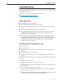
Troubleshooting
This section provides information on how to detect and resolve problems with
AT-9900 Series switches.
Other sources of useful troubleshooting information are:
■
http:// www.alliedtelesyn.co.nz/support
■
The AT-9900 Series Software Reference.
Check these first
■
Check the power cord connections.
■
Check that the power supply voltage is stable.
■
Check that the correct data cables are used and that their connections are
secure.
■
Make sure that other network devices work properly.
■
Use the show install command to check that the latest software release is
loaded. How to obtain the latest software release is described in the
AT-9900 Series Software Reference.
■
If the switch malfunctions, reboot it. Either use a small diameter pin to
operate the recessed Reset button on the switch’s front panel or enter the
command restart reboot. Alternatively, shut down and restart the switch at
either the mains power source (AC models) or use the Run/Standby
switch on the PSU (DC models).
Link/Activity LED on any port is off
This can indicate:
■
A loose data cable.
■
The device at the other end of the connection does not work properly or is
turned off.
■
The data cable is not wired correctly.
■
The network administrator has manually disabled the port through the
software.
■
The port’s selected transmission mode does not match that of the attached
device.
Perform these steps in sequence:
1.
Make sure the data cable connections are secure.
2.
Make sure the device at the other end of the connection is switched on and
works properly.
3.
Check that the data cable is wired correctly.
4.
If you can, log in and check the port status. How to log in is described in
“How to log in” on page 14
5.
If the port is enabled, make sure the transmission speed matches that of the
connected device (auto-negotiating, full or half-duplex).
C613-03084-00 REV A
Hardware Reference
43
Note If the port is disabled, someone has used the software to manually disable
it. You should find out why the port was disabled before you enable it.
Power LED is off
This can indicate:
■
A loose power cord.
■
A power supply failure.
■
A FOM is installed in that bay.
Perform these steps in sequence:
1.
Check that the power cord connections are secure.
2.
Check that all switches and circuit protection devices are in the ON position.
3.
Ensure that the supply voltage is within the operational range.
•
AC models: 100 V to 240 V AC, 47 Hz to 63 Hz
•
DC models: 40 V to 60 V DC
Fault LED is on
This can indicate:
■
There is a problem with the switch.
■
The switch or management software is malfunctioning.
■
A hardware fault is preventing switch start-up.
Perform these steps in sequence:
1.
Check “LEDs and What They Mean” on page 23 for descriptions and
explanations of LED flashing sequences.
2.
Reset the switch. Use a small diameter pin to operate the recessed Reset
button on the switch’s front panel.
3.
If you were attempting to download software or manage the switch via the
RS-232 Terminal Port, check that connections between the Terminal Port
and local terminal or PC are secure.
If you cannot access the switch’s software because of a faulty RS-232
Terminal Port connection, you can still manage the switch via Telnet or
SNMP until the problem is fixed.
4.
C613-03084-00 REV A
Download the latest software release. How to obtain the latest software
release is described in the AT-9900 Series Software Reference.
44
AT-9900 Series Switch
Contacting Us
With locations covering all of the established markets in North America, Latin
America and Europe, Allied Telesyn provides localized sales and technical
support worldwide. To find our representative nearest you, visit Allied Telesyn
on the web at: http://www.alliedtelesyn.com.
C613-03084-00 REV A