1
Servo Knife Cutters
CSC Models
Installation
Operation
Maintenance
Troubleshooting
Instant Access
Parts and Service
(800) 458-1960
(814) 437-6861
www.conairnet.com
The Conair Group, Inc.
One Conair Drive
Pittsburgh, PA 15202
Phone: (412) 312-6000
Fax: (412)-312-6227
UGE047/1003
Record your equipment’s
model and serial number(s) and the date you
received it in the spaces
provided.
It is important to record the model and serial number(s) of
your equipment and the date you received it in the User
Guide. Our service department uses this information, along
with the manual number, to provide help for the specific
equipment you installed.
Keep this User Guide and all manuals, engineering prints and
parts lists together for documentation of your equipment.
Date:
Document Number:
UGE047/1003
Serial number(s):
Model number(s):
Power Specifications:
Amps
Volts
Phase
Cycle
DISCLAIMER: The Conair Group, Inc., shall not be liable for errors
contained in this User Guide or for incidental, consequential damages in connection with the furnishing, performance or use of this
information. Conair makes no warranty of any kind with regard to
this information, including, but not limited to the implied warranties
of merchantability and fitness for a particular purpose.
Copyright 2003
THE CONAIR GROUP, INC.
All rights reserved
INTRODUCTION . . . . . . . . . . . . . . . . . . .1-1
Purpose of the User Guide . . . . . . . . . . . . . . . . . . . . . . . . .1-2
How the Guide is Organized . . . . . . . . . . . . . . . . . . . . . . .1-2
Your Responsibilities as a User . . . . . . . . . . . . . . . . . . . . .1-2
ATTENTION: Read this so no one gets hurt . . . . . . . . . . .1-3
How to Use the Lockout Device . . . . . . . . . . . . . . . . . . . .1-5
TABLE OF
CONTENTS
DESCRIPTION . . . . . . . . . . . . . . . . . . . .2-1
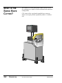
What is the Servo Cutter? . . . . . . . . . . . . . . . . . . . . . . . . .2-2
Typical Applications . . . . . . . . . . . . . . . . . . . . . . . . . . . . .2-3
How the Servo Cutter Works . . . . . . . . . . . . . . . . . . . . . . .2-4
Servo Cutter Features . . . . . . . . . . . . . . . . . . . . . . . . . . . . .2-6
Specifications . . . . . . . . . . . . . . . . . . . . . . . . . . . . . . . . . .2-7
Optional Equipment . . . . . . . . . . . . . . . . . . . . . . . . . . . . . .2-8
INSTALLATION . . . . . . . . . . . . . . . . . . . .3-1
Unpacking the Boxes . . . . . . . . . . . . . . . . . . . . . . . . . . . . .3-2
Preparing for Installation . . . . . . . . . . . . . . . . . . . . . . . . . .3-3
Positioning the Servo Cutter . . . . . . . . . . . . . . . . . . . . . . .3-4
Connecting the Main Power Source . . . . . . . . . . . . . . . . . .3-6
Installing the Encoder . . . . . . . . . . . . . . . . . . . . . . . . . . . .3-7
Installing the Cutter Blades . . . . . . . . . . . . . . . . . . . . . . . .3-8
Mounting the Cutter Bushings . . . . . . . . . . . . . . . . . . . . . .3-9
Checking Repeatability . . . . . . . . . . . . . . . . . . . . . . . . . .3-10
Preparing for Testing . . . . . . . . . . . . . . . . . . . . . . . . . . . .3-11
Testing the Installation . . . . . . . . . . . . . . . . . . . . . . . . . . .3-11
OPERATION . . . . . . . . . . . . . . . . . . . . . .4-1
The Cutter Control Feature . . . . . . . . . . . . . . . . . . . . . . . .4-2
Before Starting . . . . . . . . . . . . . . . . . . . . . . . . . . . . . . . . .4-3
Powering Up . . . . . . . . . . . . . . . . . . . . . . . . . . . . . . . . . . .4-3
Main Screen . . . . . . . . . . . . . . . . . . . . . . . . . . . . . . . . . . .4-5
Preset to Run . . . . . . . . . . . . . . . . . . . . . . . . . . . . . . . . . .4-10
Time Preset . . . . . . . . . . . . . . . . . . . . . . . . . . . . . . . . . . .4-11
Cut Mode . . . . . . . . . . . . . . . . . . . . . . . . . . . . . . . . . . . . .4-18
Maintenance Area . . . . . . . . . . . . . . . . . . . . . . . . . . . . . .4-19
Encoder Area . . . . . . . . . . . . . . . . . . . . . . . . . . . . . . . . . .4-20
Unit of Measure . . . . . . . . . . . . . . . . . . . . . . . . . . . . . . . .4-22
Scale Distance . . . . . . . . . . . . . . . . . . . . . . . . . . . . . . . . .4-23
Homing . . . . . . . . . . . . . . . . . . . . . . . . . . . . . . . . . . . . . .4-25
Offset Example . . . . . . . . . . . . . . . . . . . . . . . . . . . . . . . .4-26
Preventative Maintenance . . . . . . . . . . . . . . . . . . . . . . . . .4-27
Power On Time . . . . . . . . . . . . . . . . . . . . . . . . . . . . . . . .4-28
Checking Cut Quality . . . . . . . . . . . . . . . . . . . . . . . . . . .4-29
Starting the Servo Cutter . . . . . . . . . . . . . . . . . . . . . . . . .4-29
Making Adjustments During Operation . . . . . . . . . . . . . .4-30
Stopping the Servo Cutter . . . . . . . . . . . . . . . . . . . . . . . .4-31
UGE047/1003
CSC Servo Knife Cutters
i
MAINTENANCE . . . . . . . . . . . . . . . . . . . .5-1
Maintenance Features . . . . . . . . . . . . . . . . . . . . . . . . . . . .5-2
Warnings and Cautions . . . . . . . . . . . . . . . . . . . . . . . . . . .5-2
Maintenance Overview . . . . . . . . . . . . . . . . . . . . . . . . . . .5-4
Preventative Maintenance Schedule . . . . . . . . . . . . . . . . . .5-4
Checking the Blades . . . . . . . . . . . . . . . . . . . . . . . . . . . . .5-6
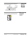
Inspecting Cutter Bushing Screws . . . . . . . . . . . . . . . . . . .5-7
Checking the Closure Latch . . . . . . . . . . . . . . . . . . . . . . . .5-7
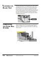
Cleaning the Blade Tray . . . . . . . . . . . . . . . . . . . . . . . . . .5-8
Lubricating the Slide Rail System . . . . . . . . . . . . . . . . . . .5-8
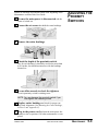
Adjusting the Proximity Switches . . . . . . . . . . . . . . . . . . .5-9
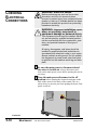
Checking Electrical Connections . . . . . . . . . . . . . . . . . . .5-10
Checking Torque . . . . . . . . . . . . . . . . . . . . . . . . . . . . . . .5-12
TROUBLESHOOTING . . . . . . . . . . . . . . . .6-1
Before Beginning . . . . . . . . . . . . . . . . . . . . . . . . . . . . . . . .6-2
A Few Words of Caution . . . . . . . . . . . . . . . . . . . . . . . . . .6-2
Identify the Cause of a Problem . . . . . . . . . . . . . . . . . . . . .6-3
Electrical Problems . . . . . . . . . . . . . . . . . . . . . . . . . . . . . .6-4
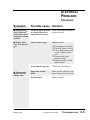
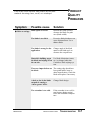
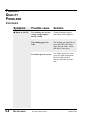
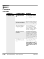
Product Quality Problems . . . . . . . . . . . . . . . . . . . . . . . . .6-8
Replacing Safety and Proximity Switches . . . . . . . . . . . .6-12
Checking the Servo Amplifier . . . . . . . . . . . . . . . . . . . . .6-12
Adjusting the Proximity Switches . . . . . . . . . . . . . . . . . .6-13
Checking the Encoder . . . . . . . . . . . . . . . . . . . . . . . . . . .6-14
Checking the Motor/Reducer Assembly . . . . . . . . . . . . . .6-15
Checking Repeatability . . . . . . . . . . . . . . . . . . . . . . . . . .6-16
APPENDIX . . . . . . . . . . . . . . . . . . . . . . . . .
Customer Service Information . . . . . . . . . . . . . . . . . . . . . .A-1
Warranty Information . . . . . . . . . . . . . . . . . . . . . . . . . . . .A-2
Cutter Blade Selection and Use . . . . . . . . . . . . . . . . . . . . .B-1
Cutting Tips . . . . . . . . . . . . . . . . . . . . . . . . . . . . . . . . . . .B-3
Calculating Blade Interruption . . . . . . . . . . . . . . . . . . . . . .B-4
Conair Cutter Blades . . . . . . . . . . . . . . . . . . . . . . . . . . . . .B-6
All About Cutter Bushings . . . . . . . . . . . . . . . . . . . . . . . .C-1
Blade and Bushing Lubrication . . . . . . . . . . . . . . . . . . . . .D-1
Operator Display Overview. . . . . . . . . . . . . . . . . . . . . . . . B-6
PARTS/DIAGRAMS
This section has been provided for you to
store spare parts lists and diagrams.
ii
CSC Servo Knife Cutters
UGE047/1003
INTRODUCTION
● Purpose of the User Guide . . . .1-2
● How the User Guide
is organized . . . . . . . . . . . . . . .1-2
● Your Responsibilities
as a User . . . . . . . . . . . . . . . .1-2
● ATTENTION: Read this so
no one gets hurt . . . . . . . . . . .1-3
● How to Use the
Lockout Device . . . . . . . . . . . .1-5
UGE047/1003
CSC Servo Knife Cutters
1-1
PURPOSE OF
THE USER
GUIDE
This User Guide describes the Conair CSC Servo Knife Cutter
and explains step-by-step how to install, operate, maintain and
repair this equipment.
HOW THE USER
GUIDE IS
ORGANIZED
Symbols have been used to help organize the User Guide and
call your attention to important information regarding safe
installation and operation.
YOUR
RESPONSIBILITY
AS A USER
Before installing this product, please take a few moments to
read the User Guide and review the diagrams and safety information in the instruction packet. You also should review manuals covering associated equipment in your system. This
review won’t take long, and it could save you valuable installation and operating time later.
Symbols within triangles warn of conditions that could
be hazardous to users or could damage equipment.
Read and take precautions before proceeding.
1
Numbers within shaded squares indicate tasks or steps
to be performed by the user.
◆
A diamond indicates the equipment’s response to an
action performed by the user.
❒
●
An open box marks items in a checklist.
A shaded circle marks items in a list.
You must be familiar with all safety procedures concerning
installation, operation and maintenance of this equipment.
Responsible safety procedures include:
● Thorough review of this User Guide, paying particular
attention to hazard warnings, appendices and related diagrams.
● Thorough review of the equipment itself, with careful
attention to voltage sources, intended use and warning
labels.
● Thorough review of instruction manuals for associated
equipment.
● Step-by-step adherence to instructions outlined in this
User Guide.
1-2
INTRODUCTION
CSC Servo Knife Cutters
UGE047/1003
We design equipment with the user’s safety in mind. You can
avoid the potential hazards identified on this machine by following the procedures outlined below and elsewhere in the
User Guide.
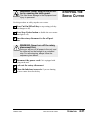
DANGER: Sharp blades!
ATTENTION:
READ THIS
SO NO
ONE GETS HURT
Most injuries caused by knife blades occur
when the cutter has been turned off. Handle
blades with care at all times.
● Always wear cut-resistant gloves when the
cutting chamber is open and when handling
blades.
● Always lock out the cutter before opening the
cutting chamber.
● Always wait until the cutter head has stopped
completely before opening the knife guard.
CSC cutters are equipped with several safety
devices to ensure safe operation. Never remove
or disable these devices to sustain production.
Operating without these devices can cause
severe injury.
● When the knife guard is opened, the knife
guard switch stops the cutter.
● Two proximity-type safety switches prevent
operation unless the cutter bushings are in
place.
● The STOP button activates a circuit that
stops the knife.
WARNING: Improper installation, operation, or servicing may result in
equipment damage or personal injury.
This equipment should only be installed, adjusted, and serviced by qualified technical personnel who are familiar with the construction, operation, and potential hazards of this type of
machine.
All wiring, disconnects, and fuses should be
installed by qualified electrical technicians in
accordance with electrical codes in your region.
Always maintain a safe ground. Do not operate
the equipment at power levels other than what
is specified on the machine serial plate.
UGE047/1003
CSC Servo Knife Cutters
INTRODUCTION
1-3
ATTENTION:
READ THIS
SO NO
ONE GETS HURT
WARNING: Voltage Hazard
This equipment is powered by high voltage
alternating current, as specified on the machine
serial tag and data plate.
A properly-sized conductive ground wire from
the incoming power supply must be connected
to the chassis ground terminal inside the electrical enclosure. Improper grounding can result in
severe personal injury and erratic machine
operation.
Always disconnect and lockout power before
opening the electrical enclosure or performing
non-routine procedures such as maintenance.
1-4
INTRODUCTION
CSC Servo Knife Cutters
UGE047/1003
WARNING: Electrical hazard
Before performing maintenance or repairs on
this product, disconnect and lock out electrical
power sources to prevent injury from unexpected energization or start-up. A lockable device
has been provided to isolate this product from
potentially hazardous electricity.
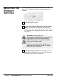
HOW TO USE
THE LOCKOUT
DEVICE
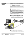
Lockout is the preferred method of isolating machines or
equipment from energy sources. Your Conair product is
equipped with the lockout device pictured below. To use the
lockout device:
1
2
Stop or turn off the equipment.
Isolate the equipment from
electrical power.
Turn the rotary disconnect switch to
OFF or O position.
3
Secure the device with an
assigned lock or tag.
4
The equipment is now locked
out.
CAUTION: Moving parts
Before removing lockout devices and returning
switches to the ON position, make sure that all
personnel are clear of the machine, tools have
been removed and all safety guards are reinstalled.
UGE047/1003
CSC Servo Knife Cutters
INTRODUCTION
1-5
DESCRIPTION
● What is the Servo
Knife Cutter? . . . . . . . . . . . . . .2-2
● Typical Applications . . . . . . . . . .2-3
● How the Servo Cutter Works . . .2-4
● Servo Cutter Features . . . . . . . .2-6
● Specifications . . . . . . . . . . . . . .2-7
● Optional Equipment . . . . . . . . . .2-8
UGE047/1003
CSC Servo Knife Cutters
2-1
WHAT IS THE
SERVO KNIFE
CUTTER?
2-2
DESCRIPTION
The Conair CSC Series Servo Knife Cutter is an on- or offline cutting device capable of both on-demand and continuous
cutting modes.
CSC cutters utilize a positional-controlled servo motor to
achieve cut-to-part position repeatability within 0.1 millisecond.
CSC Servo Knife Cutters
UGE047/1003
Conair CSC Series Servo Knife Cutters can cut extrudable
plastics and rubber both on- and off-line. Other extrudable
materials-foods, ceramics, magnets, soaps, etc.-may also be
cut depending on specific application requirements.
TYPICAL
APPLICATIONS
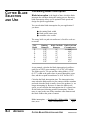
CSC cutters are available with different cutting capacities (2,
3, 4, and 5 inches) to suit your specific needs. The servo
motor size and cutter head material may also be optimized for
specific applications. While the standard cutter orientation is
right-to-left, cutters can also be made with a left-to-right orientation (see Specifications, Section 2). (The illustrations in
this User Guide represent the standard right-to-left configuration.)
CSC cutters are limited to a specific range of product sizes
based on each unit's cutting capacity. CSC cutters can operate
over a range of speeds (depending on which options were purchased.) See Specifications, Section 2.
Different materials, line speeds, temperatures and material
cross-sections can result in different cutting torques. If you are
changing any of these parameters, consult your Conair service
personnel to be sure your equipment can handle the changes.
UGE047/1003
CSC Servo Knife Cutters
DESCRIPTION
2-3
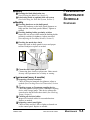
HOW THE
SERVO CUTTER
WORKS
Extruded material that has been sized and cooled enters the
cutter from the upstream side (see How the Servo Cutter
Works continued, Section 2, step 1). Typically, a puller is
placed just before the cutter; the puller pulls the extrudate
through the sizing and/or cooling tanks and feeds it into the
cutter.
The positional servo motor, is direct coupled to the cutter
head, or an in-line planetary gear reducer that drives the cutter
head. The planetary gear reducer arrangement increases cutting torque, improves servo motor efficiency, and offers
improved bearing load ratings.
The cutting knife, attached to the cutter head, is driven by the
servo motor (see How the Servo Cutter Works continued,
Section 2, step 2). Two cutter bushings guide and support both
the extrudate and the cutting knife. The cutter head is mounted
directly to the in-line planetary gear reducer shaft using a
Trantorque coupling device, and may have as many as four
optional blade positions.
Two types of cutting modes are available. On-demand cutting
modes (Timer, Encoder, Auto and Product) provide a single
rotation cut cycle. However, in continuous cutting modes
(Flywheel and optional Follower) the cutting mechanism
rotates continuously.
The knife guard includes a stainless steel lower tray, which
can be used for blade lubrication. The upper knife guard
includes a clear polycarbonate window. This allows you to
watch the cutting blade during operation.
Cut pieces are collected or carried on to further processing by
an optional conveyor (see How the Servo Cutter Works continued, Section 2, step 3).
2-4
DESCRIPTION
CSC Servo Knife Cutters
UGE047/1003
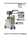
HOW THE
SERVO CUTTER
WORKS
CONTINUED
The cutter head holds
2 the blade(s) as they
rotate and pass between the
bushings, cutting the extrudate.
Cut pieces are collected or
1 carried away on a conveyor.
Extruded material enters the
3 cutter from the upstream side.
UGE047/1003
CSC Servo Knife Cutters
DESCRIPTION
2-5
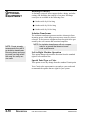
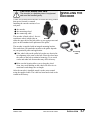
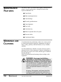
SERVO CUTTER
FEATURES
The CSC Servo Cutter models have these features:
Eye-level Control
Servo motor and in-line
planetary gear reducer
Hinged and interlocked
stainless steel blade cover
Cutter head with blade(s)
as seen through clear viewing panel
Stainless steel blade
lubrication tray
Material inlet through cutter bushings
Swivel casters and
lock down screws
2-6
DESCRIPTION
CSC Servo Knife Cutters
UGE047/1003
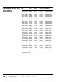
SPECIFICATIONS
A
B
D
C
MODELS
CSC2L
Performance characteristics
Extrudate capacity,
in. {mm} dia.
1.25 {318}
Blade drive motor, Hp {kW}
2.7{1.86}
High torque motor*
N/A
Feed direction
right->left
Dimensions in. {mm}
A - Height
63 {1600}
B - Height to centerline
42 ± 2
40 {1016}
C - Width
36 {914}
D - Depth
24 {614}
Weight lbs. {kg}
Installed
600 {272}
Shipping
700 {317}
Total Amps for Volt/phase/Frequency
230V/1/60Hz
16.6A
208V/1/60Hz*
18.3A
460V/1/60Hz*
8.3A
575V/1/60Hz*
6.6A
230V/3/60Hz
N/A
208V/3/60Hz*
N/A
460V/3/60Hz*
N/A
575V/3/60Hz*
N/A
Cutter Head
Aluminum 2-position
Yes
SS Steel 2-position*
Cutter Control
Slide Base*
CSC3L
CSC4L
CSC2
CSC3
CSC4
CSC5
2.25 {572}
3.25 {823}
1.75 {445}
2.75 {699}
3.75 {953}
4.75{1207}
2.7 {1.86}
N/A
right->left
2.7 {1.86}
N/A
right->left
2.7 {1.86}
3.8 {2.8}
right->left
2.7 {1.86}
3.8 {2.8}
right->left
3.8 {2.8}
STD
right->left
3.8 {2.8}
STD
right->left
63 {1600}
63 {1600}
63 {1600}
63 {1600}
63 {1600}
63 {1600}
40 {1016}
36 {914}
24 {614}
40 {1016}
36 {914}
24 {614}
40 {1016}
36 {914}
24 {614}
40 {1016}
36 {914}
24 {614}
40 {1016}
36 {914}
24 {614}
40 {1016}
36 {914}
24 {614}
600 {272}
700 {317}
600 {272}
700 {317}
600 {272}
700 {317}
600 {272}
700 {317}
600 {272}
700 {317}
600 {272}
700 {317}
16.6A
18.3A
8.3A
6.6A
N/A
N/A
N/A
N/A
16.6A
18.3A
8.3A
6.6A
N/A
N/A
N/A
N/A
16.6A
18.3A
8.3A
6.6A
18
20
9
7
16.6A
18.3A
8.3A
6.6A
18
20
9
7
N/A
N/A
N/A
N/A
18
20
9
7
N/A
N/A
N/A
N/A
18
20
9
7
Yes
Yes
Yes
Yes
____
____
____
____
____
Yes
Yes
STD
STD
Redlion
Redlion
Redlion
Redlion
Redlion
Redlion
Redlion
Yes*
Yes*
Yes*
Yes*
Yes*
Yes*
Yes*
*Optional
UGE047/1003
CSC Servo Knife Cutters
DESCRIPTION
2-7
OPTIONAL
EQUIPMENT
Cutting torque upgrades
Several options can be used to increase the cutting torque:
● CSC-2 and 3 cutters can be upgraded from a 2.7 HP
(MGE-455) to a 3.8 HP (MGE-490) servo motor. (The
larger servo motor is standard on CSC-4 and 5 cutters.)
● The standard aluminum cutter-head can be replaced with a
heavier stainless steel one. When this option is picked, the
maximum number of cuts per minute decreases from 400
to 200. Inertia, and thus cutting torque, is increased significantly.
Follower Cutting Mode
Follower mode allows the operator to program the desired cut
length and the number of blades. The controller then automatically follows the encoder and adjusts the speed of the cutter
head to maintain cut length. This is known as an electronic
gearlock system. The cut length accuracy is maintained even if
the puller changes speed. A 3,000 pulse per revolution encoder
is used for this option using the Quadrature (x-4) mode, giving
12,000 pulses per foot for extreme accuracy and repeatability.
Slide Base
This option is highly recommended for cutting flexible extrudates. While the cutter base is fixed and aligned with the
puller, the cutter itself is mounted on a set of linear slides that
allow as much as 6 inches of movement. The cutter can be
moved away from the puller for startup, then moved close to
the puller to enhance delivery to the cutter bushings.
Bushing Lubrication
This is a self-contained spray system, which includes a reservoir and air inlet for operation at 20-30 psig (air source not
included). A flexible nozzle directs lubricant onto the extrudate as it enters the cutter bushings. This decreases bushing
drag and helps lubricate the blade. This option is particularly
recommended for processing sticky/soft (low durometer)
materials.
Auto Cutting Mode
Auto Cutting mode allows the operator to program the desired
cut length and the number of blades and desired blade speed.
The controller then automatically follows the encoder and
adjusts the speed of the cutter head to maintain cut length at
desired blade speed. This is known as an electronic gearlock
system. The cut length accuracy is maintained even if the
puller changes speed. A 3,000 pulse per revolution encoder is
used for this option using the Quadrature (x-4) mode, giving
12,000 pulses per foot for extreme accuracy and repeatability.
2-8
DESCRIPTION
CSC Servo Knife Cutters
UGE047/1003
Blade Wipe
The blade wipe system keeps the cutting blade clean by
removing lubricant and particles from the blade. A felt pad
sandwiched between two pieces of stainless steel and mounted
in the stainless steel blade lubrication tray wipes the knife
before each cut.
OPTIONAL
EQUIPMENT
Multiple batch and length mode
This advanced cutter control offers many additional features:
● Four preset cut lengths with individual outputs and a batch
output
● Cuff sequencing mode for multiple cutting per cuff
End Sense
This option allows the use of an electric eye to produce a cut
signal. Two types of electric eye brackets are included:
● A bracket for cutting parts 3.5-24 inches long. This bracket is mounted on the bushing holder, and uses a triplebeam eye with a red dot for easy setup and alignment.
Coarse and fine adjustments are provided with the eye
positioned above the extrudate.
NOTE: With this bracket and eye mounting, the
part must be rigid enough not to sag or
flex at the cut distance.
● A bracket for cutting parts up to 10 feet long. This bracket
is designed to mount on a discharge conveyor. The electric eye used with this bracket is a through beam type and
can be adjusted to pick up products that are at least 0.100
inches high (height of piece above the conveyor).
UGE047/1003
CSC Servo Knife Cutters
DESCRIPTION
2-9
OPTIONAL
EQUIPMENT
Discharge Conveyor
A discharge conveyor offers support before, during, and after
cutting, and facilitates the removal of cut parts. Discharge
conveyors are available in the following sizes:
● 6 inches wide by 6 feet long
● 6 inches wide by 10 feet long
● 6 inches wide by 16 feet long
Isolation Transformer
The isolation transformer protects sensitive electronics from
incoming power, which helps prevent errors caused by electrical noise. It also protects equipment from electrical noise generated by the servo motor and associated amplifier.
NOTE: Conair strongly
recommends the use of
an isolation transformer.
Ensuring clean and proper power can help avoid
the need for costly service calls.
NOTE: An isolation transformer will not compensate for a ground that does not meet
code requirements.
Left to Right Machine Operation
This option changes the machine direction from the standard
right to left extrusion flow.
Special Paint Type or Color
This option covers any change from the standard Conair paint.
Your Conair sales representative can analyze your needs and
recommend the options that are right for your system.
2-10
DESCRIPTION
CSC Servo Knife Cutters
UGE047/1003
INSTALLATION
● Unpacking the Boxes . . . . . . . . .3-2
● Preparing for Installation . . . . . .3-3
● Positioning the Servo Cutter . . .3-4
● Connecting the Main
Power Source . . . . . . . . . . . . .3-6
● Installing the Encoder . . . . . . . .3-7
● Installing the Cutter
Blades . . . . . . . . . . . . . . . . . . .3-8
● Mounting the Cutter
Bushings . . . . . . . . . . . . . . . . .3-9
● Checking Repeatability . . . . . .3-10
● Preparing for Testing . . . . . . . . .3-11
● Testing the Installation . . . . . . .3-11
UGE047/1003
CSC Servo Knife Cutters
3-1
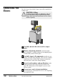
UNPACKING THE
BOXES
The CSC Series Servo Knife Cutter comes fully assembled in
a single crate.
CAUTION: Lifting
To avoid personal injury or damage to the cutter, lift the cutter using a forklift or hoist with
straps that have been positioned at the cutter's
center of gravity.
3-2
INSTALLATION
1
Carefully uncrate the cutter and its components.
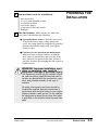
2
Remove all packing material, protective paper,
3
Carefully inspect all components to make sure no
4
Record serial numbers and specifications in the
blanks provided on the back of the User Guide's title
page. This information will be helpful if you ever need
service or parts.
5
You are now ready to begin installation.
tape, and plastic. Compare contents to the shipping papers
to ensure that you have all the parts.
damage occurred during shipping. Check all wire terminal
connections, bolts, and any other electrical connections,
which may have come loose during shipping.
(See Preparing for Installation, Section 3), for completing
the preparation steps.
CSC Servo Knife Cutters
UGE047/1003
1
You need these tools for installation:
❒
❒
❒
❒
❒
❒
2
wire strain relief
16- or 18-inch adjustable wrench
set of Allen wrenches
set of feeler gauges
½ inch open or box end wrench
flashlight
PREPARING FOR
INSTALLATION
Plan the location. Make sure the area where the
servo cutter is installed has the following:
● A grounded power source. Check the cutter’s serial tag for the correct amps, voltage, phase and
cycles. All wiring should be completed by qualified
personnel and should comply with your region’s
electrical codes.
● Clearance for safe operation and maintenance.
Make sure there is enough clearance around the
servo cutter for maintenance and servicing. If the
servo cutter has the optional slide base, be sure to
check for clearance by extending the slide system in
both directions.
WARNING: Improper installation, operation, or servicing may result in
equipment damage or personal injury.
This equipment should only be installed, adjusted, and serviced by qualified technical personnel who are familiar with the construction, operation, and potential hazards of this type of
machine.
All wiring, disconnects, and fuses should be
installed by qualified electrical technicians in
accordance with electrical codes in your region.
Always maintain a safe ground. Do not operate
the equipment at power levels other than what
is specified on the machine serial tag and data
plate.
UGE047/1003
CSC Servo Knife Cutters
INSTALLATION
3-3
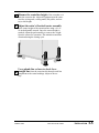
POSITIONING
THE SERVO
CUTTER
1
Move the servo cutter into position. Place the
servo cutter in position downstream of the belt puller.
CAUTION: Lifting
To avoid personal injury or damage to the cutter, lift the cutter using a forklift or hoist with
straps that have been positioned at the cutter's
center of gravity.
Cutter
2
Determine the best distance from the belt puller to
the CSC cutter.
● For flexible products, the cutter should be as close
as possible to the puller.
● For rigid products, leave enough space to allow the
product to flex during the cutting cycle. In some
cases, it may be necessary to allow 6-8 feet between
the puller and cutter.
3
3-4
INSTALLATION
Align the cutter with the extrusion line.
CSC Servo Knife Cutters
UGE047/1003
4
Measure the centerline height of the extrudate as it
exits the extrusion die. Adjust all equipment on the extrusion line (sizing tank, cooling tanks, belt puller, and cutter) to this height.
5
Adjust the cutter's floorlock/caster assembly
6
Use a plumb line or laser to check for a
straight line from the extrusion die through each line
to the center height of the extrusion line using a 16- or
18-inch adjustable wrench. Once the correct height is
reached, adjust the pad assembly to remove the weight
from the casters for operation. This minimizes machine
vibration during the cutting cycle.
component to the cutter bushings. Adjust as necessary.
UGE047/1003
CSC Servo Knife Cutters
INSTALLATION
3-5
CONNECTING
THE MAIN
POWER SOURCE
WARNING: Electrical hazard
Before performing any work on this product, disconnect and lock out electrical power sources
to prevent injury from unexpected energization
or start-up. A lockable device has been provided to isolate this product from potentially hazardous electricity.
WARNING: Improper installation, operation, or servicing may result in
equipment damage or personal injury.
This equipment should only be installed, adjusted, and serviced by qualified technical personnel who are familiar with the construction, operation, and potential hazards of this type of
machine.
All wiring, disconnects, and fuses should be
installed by qualified electrical technicians in
accordance with electrical codes in your region.
Always maintain a safe ground. Do not operate
the equipment at power levels other than what
is specified on the machine serial tag and data
plate.
IMPORTANT: Always refer to
the wiring diagrams that
came with your servo cutter
before making electrical connections. The diagrams show
the minimum size main power
cable required for your cutter,
and the most accurate electrical component information.
3-6
INSTALLATION
1
Open the servo cutter’s electrical
enclosure. Turn the disconnect dial on the
door to the Off or O position and open the
door.
2
Insert the main power wire through the knockout
in the side of the enclosure. Secure the wire with a rubber
compression fitting or strain relief.
3
Connect the power wires to the terminals indicated
4
Check every terminal screw to make sure wires are
5
Connect the ground wire to either grounding point
on the wiring diagram that came with your machine.
secure. Gently tug each wire.
If a wire is loose, use a screwdriver to tighten the terminal.
shown in the diagram.
CSC Servo Knife Cutters
UGE047/1003
CAUTION: Handle with care.
The encoder is a delicate piece of equipment
and must be handled gently.
INSTALLING THE
ENCODER
Conair uses bi-directional encoders to ensure that only product
that moves forward is counted.
Installing the encoder consists of several parts:
● the encoder
● the measuring wheel
● the connecting cable
The encoder is fitted with a 1 foot circumference wheel which rides on
Encoder
either the upper belt of the belt puller or (for rigid profiles and
pipe) on the extrudate itself upstream of the puller.
The encoder is supplied with an integral mounting bracket.
How and where you attach the encoder to the puller depends
on your particular puller and application.
● If the wheel rides on the puller belt, make sure that its linear alignment is the same as the belt. Place the wheel near
the center of the belt to minimize bouncing. Try to avoid
cracks and other belt features that may affect accuracy.
Wheels
Connecting
Cable
● Make sure the location allows you to keep the wheel
clean. Any small buildup on the wheel will affect its circumference and change the cut length.
After the encoder is installed, attach it to the cutter control
using the supplied cable. The cable has been hard-wired to the
control at the factory.
UGE047/1003
CSC Servo Knife Cutters
INSTALLATION
3-7
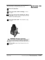
INSTALLING THE
CUTTER
BLADES
DANGER: Sharp blades!
Most injuries caused by knife blades occur
when the cutter has been turned off. Handle
blades with care at all times.
● Always wear cut-resistant gloves when the
cutting chamber is open and when handling
blades.
● Always lock out power to the cutter before
opening the cutting chamber.
● Always wait until the cutter head has completely stopped before opening the knife
guard.
CSC cutters are equipped with several safety
devices to ensure safe operation. Never remove
or disable these devices to sustain production.
Operating without these devices can cause
severe injury.
● When the knife guard is opened, the
knife guard switch stops the cutter.
● Two proximity-type safety switches prevent
operation unless the cutter bushings
are in place.
● The STOP button activates a circuit that
stops the cutter head.
Attach blade to cutter
head with blade screw.
For more information about choosing the appropriate blade
for your material, see the Appendix B.
3-8
INSTALLATION
CSC Servo Knife Cutters
UGE047/1003
DANGER: Sharp blades!
Always wear cut-resistant gloves when the cutting chamber is open and when handling
blades. Never open cutting chamber without
locking out the cutter power and waiting until
the cutter head stops spinning.
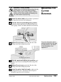
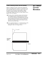
1
Rotate the cutter head until the blade is positioned
2
Slide the downstream bushing into position,
in the gap between where the bushings go.
positioning it up to and barely touching the blade (use
feeler gauge). NOTE: the blade should not be deflected.
Upstream
Downstream
3
MOUNTING THE
CUTTER
BUSHINGS
Tighten the set screw against the flat side of the
bushing to hold the bushing in position.
For more information about
setting and adjusting the gap
for the bushings, see About
Cutter Bushings in the
Appendix C.
Location of set screws
4
Slide the upstream bushing into position, posi-
5
Tighten the set screw against the flat side of the
6
Rotate the cutter head by hand to make sure the
tioning it up to but not touching the blade (using feeler
gauge).
bushing to hold the bushing in position.
bushings did not move, and the the blade still passes
through the gap between the bushings.
UGE047/1003
CSC Servo Knife Cutters
INSTALLATION
3-9
CHECKING
REPEATABILITY
Before any Conair puller/cutters are shipped, they are tested
for cut time repeatability to be sure they are within performance specifications. The repeatability test checks the performance of the rotary knife cutter to return the home park position after a complete cut. Acceptable repeatability times
allowed for each cutter model prior to shipping are:
Type of Cutter
Repeatability Time
AC Pneumatic Cutter
DC Pneumatic Cutter
Positional Servo
Less than 1 millisecond
Less than 1.5 millisecond
Less than 0.1 millisecond
Note: 1-millisecond at 60 feet per minute is equal to .012 inches.
The repeatability mode is built into the Conair cutter controls
and allows you to perform similar tests, without any external
test equipment. It is recommended that you check repeatability
on a regular basis. Acceleration/deceleration delays of the
servo do not contribute to repeatability error; any error is
attributed solely to motor stability, couplings, assembly,
power, and proximity sensor alignment.
Use any blade speed and line speed. The line speed is only
seen while in the Encoder or Product modes. It is recommended that the tests be performed at cut intervals between 0.5 and
5-seconds. Do not change the blade speed or the line speed
after starting the test.
To test repeatability:
1
Turn on the cutter. Perform the test in encoder mode
with the cutter on-line. The Display will read: DevCP
shows problems with the cutter. DevCC shows problems
with the puller.
2
Press the menu key to display operator functions.
3
4
Press soft key test to display DevCP screen.
5
Press soft key on/off to start the
testing and display the results.
Press next key displays DevCC
results.
Note: Previous key returns to DevCP screen.
Repeat the test by pressing the Reset Cut button to begin
a new sample period.
To end the Repeatability test, press soft key on/off or exit.
3-10
INSTALLATION
CSC Servo Knife Cutters
UGE047/1003
1
Make sure all components are installed according
2
Check that the cutter is firmly locked into posi-
3
Check that all wiring conforms to electrical
codes, and all wiring covers are in place.
1
Turn on the main disconnect. Plug in the main
power cord and turn on the main disconnect. The display
should fully illuminate and bootup. The amber power on
light illuminates.
2
Check that the E-Stop button is in the out,
extended position. NOTE: If the E-Stop button is
to assembly drawings. Make sure that all bolts on the cutter have been tightened.
PREPARING
TESTING
FOR
tion with the anchoring screws.
TESTING THE
INSTALLATION
pushed in, there will be no power applied to the amplifier
and the operator interface will display “starting commands” for an extended period of time.
3
Make sure that the Cut On\Off is Off.
4
Press Start Cutter button. The light in the button
should light. On CSC cutters, the cutter head will make
one revolution until it finds its home offset position.
Open the knife guard. The machine start push
Note: If “Home Runtime Failed” message is displayed. Check for malfunctions of misadjusted
sensor.
5
button should go out.
If necessary, press button to display off.
If the cutter is not working properly at any time, turn it off
immediately and refer to the Troubleshooting section of this
User Guide.
If you do not encounter any problems, proceed to the
Operation section.
INSTALLATION
UGE047/1003
CSC Servo Knife Cutters
3-11
OPERATION
● The Cutter Control . . . . . . . . . . .4-2
● Before Starting . . . . . . . . . . . . . .4-3
● Powering Up . . . . . . . . . . . . . . . .4-3
● Main Screen . . . . . . . . . . . . . . . .4-5
● Total Screen . . . . . . . . . . . . . . . .4-6
● Batch Screen . . . . . . . . . . . . . . .4-7
● Length Screen . . . . . . . . . . . . . .4-9
● Preset to Run . . . . . . . . . . . . . .4-10
● Time Preset . . . . . . . . . . . . . . .4-11
● Blade Speed . . . . . . . . . . . . . . .4-13
● Function Areas . . . . . . . . . . . . .4-15
● Test Screen . . . . . . . . . . . . . . . .4-16
● Cut Mode . . . . . . . . . . . . . . . . .4-18
● Min. Measurement . . . . . . . . . .4-19
● Maintenance Area . . . . . . . . . .4-19
● Encoder Area . . . . . . . . . . . . . .4-20
● Unit of Measure . . . . . . . . . . . .4-22
● Scale Distance . . . . . . . . . . . . .4-23
● Homing . . . . . . . . . . . . . . . . . . .4-25
● Offset Example . . . . . . . . . . . . .4-26
● Preventative Maintenance . . . .4-27
● Power On Time . . . . . . . . . . . . .4-28
● Checking Cut Quality . . . . . . . .4-29
● Starting the Servo Cutter . . . . .4-29
● Making Adjustments
During the Operation . . . .4-30
● Stopping the Servo Cutter. . . . .4-31
UGE047/1003
CSC Servo Knife Cutters
4-1
The Operator Control provides an intuitive user-friendly
method to interface with the Conair Servo Cutter. Information
is viewed and entered at the Operator Control and is communicated to the servo positional amplifier via the RS-232 serial
communication link.
OPERATOR
CONTROL
FEATURES
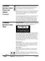
The Operator Control is a flat membrane panel consisting of
22-keys and a large 2 line x 20 back lit LCD screen.
Soft Keys-allows
the operator to
select different
functions.
CONAIR SERVO CUTTER
Version 1.0
Numeric KeysPermits data entry
for the operator
Fixed Function
Keys-Contain universal symbols &
text
Soft Keys
Soft keys - these are the three keys directly under the display.
All three have a triangle on them. Occasionally, pages will
appear that allow the operator to use one of the soft keys. On
those occasions, text would typically appear directly above
the key and the key will have a function. Think of the text as
the soft key function indicator or title. These keys will be
referred to in this manual from left to right as soft keys 1, 2
and 3 respectively.
Numeric keys
These are the black keys containing numbers 0 to 9. Numbers
permit data entry of parameters. See Raise and Lower for
value trim.
Fixed Function Keys (at Bottom)
Underneath the numeric keys are fixed function keys. They
contain universal symbols and text. The fixed function keys
are Raise, Lower, Next, Prev (previous), Enter, Delete, Exit,
Menu and Mute. These functions are described in the
"Function keys - Fixed Functions" section of this manual.
LCD Screen
The screen shows various pages depending on operator
actions. In addition, it is used to indicate warnings.
Mostly, it is used for viewing status and for setting parameters.
4-2
OPERATION
CSC Servo Knife Cutters
UGE047/1003
Before you start daily operation of the servo cutter, you need
to perform preventative maintenance. Necessary maintenance
is described in the Maintenance section of this Users Guide,
See Preventative Maintenance, Section 5.
WARNING: Be sure that power to the servo
cutter is OFF when doing any maintenance on
the servo cutter. Follow all safety rules when
performing any maintenance on this equipment.
BEFORE
STARTING
Daily maintenance includes:
● Inspecting the cutter blades
● Inspecting the blade mounting hardware
● Making sure the cutter bushings are properly secured
● Inspecting the closure latch on the knife guard
● Checking cutter alignment with extrusion line
● Performing any floor lock adjustments as needed
These items and weekly, monthly, and semi-annual maintenance procedures are detailed in the Maintenance section of
this User Guide.
1
2
Plug in the power cord to restore power after any
POWERING UP
required maintenance.
Turn on the main power. The cutter control will
bootup. The amber power on light illuminates.
NOTE: You can watch the servo motor amplifier's
status screen during bootup through the
window on the back of the electrical enclosure. This display gives information that may
be useful if you have a problem. See the
Troubleshooting section.
While the cutter is booting up, perform the next three steps:
3
Make sure the E-Stop button is in the out,
extended position.
4
Make sure that the Cut On\Off is Off.
If necessary, press button to display off.
5
Press Start Cutter button. The light in the button
should light. On CSC cutters, the cutter head will make
one revolution until it finds its home offset position.
UGE047/1003
CSC Servo Knife Cutters
Continued
OPERATION
4-3
POWERING UP
Note: If “Home Runtime Failed” message is dis
played. Check for malfunctions of misadjusted
sensor.
CONTINUED..
6
Open the knife guard. The Machine start push
button should go out.
If the cutter is not working properly at any time, turn it off
immediately and refer to the Troubleshooting section of this
User Guide.
If you do not encounter any problems, proceed to the
Operation section.
Power Up Sequence
At power up a series of system screens briefly appear. The
software is Red Lion's Edict-97. This screen or similar shows
first.
Edict-97 Runtime
Ver. 5.05.134
Next, the Communications message appears
**STARTING COMMS**
If there are any problems with communications, this screen
will remain on longer than a couple of seconds.
If there are no communication problems the Conair Servo
Cutter program will begin to run. The following message or
similar shows for 5-seconds.
CONAIR SERVO CUTTER
Version 1.0
After the 5 second delay the Main Screen will appear.
4-4
OPERATION
CSC Servo Knife Cutters
UGE047/1003
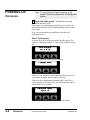
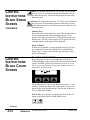
MAIN SCREEN
There are two types of main screens, length or time measurement and cuts per minute measurement. The type displayed
varies depending on the current cut mode setting.
See the mode operator display overviews.
1 ENC 00000.000 in.
Parts
Off
Length
OPERATOR
CONTROL
INSTRUCTIONS
MAIN SCREEN
The Main Screen has seven features. The top line displays the
active preset (only with multi preset option), cut mode, active
measurement and the unit of measure. The bottom line contains three soft key functions, softkey1/Parts, softkey2/cut
On/Off and softkey3, which varies depending on the current
cut mode setting.
Active Preset
With the multi preset option in on-demand modes the active
preset value changes upon batch completion. As the cutter
sequences through multiple presets, the operator always
knows which preset is being processed.
Active Measurement
The measurement value displayed will be the active length or
time preset or cuts per minute depending on the active cut
mode. It displays the value only when the machine is started
and softkey2 On/Off is on. If the machine is stopped or softkey2 On/Off is off, this counter will be forced to zero.
If a negative symbol is shown to the left of the measurement
value, the encoder signal is reversed, i.e. rotating in the wrong
direction. The Cutter will not function while the encoder is
going negative. It is possible to correct this by using the
encoder direction function located in the encoder area of the
maintenance area. See the maintenance area display overview.
Length, Time or Blade Softkey
This key is mode dependent see the mode operator display
overview for the current cut mode.
On/Off Softkey
Under the active measurement in the center of the bottom line
of the display is a soft key labeled On or Off. Pressing this
key while On is displayed will disable the cutter. Likewise
pressing this key while Off is displayed enables the cutter.
Pressing the stop button forces the cut enable off.
Manual cuts can still be made while the cut enable is off.
UGE047/1003
CSC Servo Knife Cutters
OPERATION
4-5
CONTROL
INSTRUCTIONS
Menu function key is used to access the Menu Area.
This area can only be accessed from the main display
screen for each mode. See the Menu Area section for more
information.
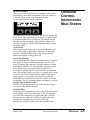
Parts Select Area Screen
Under the current mode on the left side of the bottom line of
the display is a soft key labeled Parts. Pressing this key
accesses the Parts Select Screen.
SELECT PARTS AREA
Total
Exit
Batch
This screen provides access to the parts Total/softkey1 or
Batch/softkey3 areas. Pressing Exit/softkey2 returns the display to the active main screen. If no selection is made within
30 seconds the display returns to the active main screen.
EXIT or PREV, fixed function keys return the display to the
previous screen.
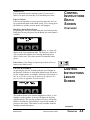
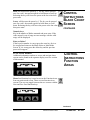
TOTAL SCREEN
CONTROL
INSTRUCTIONS
TOTAL
SCREEN
By pressing softkey1 located under the word Total on the Parts
Select Screen, a seven-decade total counter is available.
Additional information on how to access this screen can be
found in the operator display overview in Appendix E of this
manual.
TOTAL 0,000,000 pcs.
Off
Exit
Reset
This is typically used to count cut pieces during the day or
days that the product is being produced. Sample or manual
cuts are not counted. When enabled the count continues to
accumulate even if the total display is not being viewed. It is
also possible to turn this counter off or on.
Continued
4-6
OPERATION
On/Off Softkey1
Under the counter on the left is a soft key labeled On or Off.
Pressing this key while On is displayed will disable the
counter. Likewise pressing this key while Off is displayed
enables the counter.
Exit Softkey2
Under the counter, in the center is a soft key labeled Exit.
Pressing this key will return the display to the Parts Select
screen.
CSC Servo Knife Cutters
UGE047/1003
Reset Softkey3
Under the counter, on the right is a soft key labeled Reset.
Pressing this key will zero the counter.
EXIT or PREV, fixed function keys return the display to the
Parts Select screen.
BATCH SCREEN
By pressing softkey3 located under the word Batch on the
Parts Select Screen, a six-decade Batch counter is available.
Additional information on how to access this screen can be
found in the operator display overview in Appendix E of this
manual.
CONTROL
INSTRUCTIONS
TOTAL SCREEN
CONTINUED
CONTROL
INSTRUCTIONS
BATCH SCREEN
BATCH 000,000 pcs.
Change
Off
Reset
This is typically used to count the pieces required to fill a carton, with the product being cut. The batch counter counts up
to the batch preset and resets to zero. As the accumulated
count reaches the alarm preset the batch pre-warn output-3
energizes then when the batch preset is reached the batch
complete output-2 briefly energizes and both outputs turn
back off. Sample/Manual cuts are not counted. When enabled
the count continues to accumulate even if the batch display is
not being viewed. It is also possible to turn this counter off or
on.
Change Softkey1
Under the counter, on the left is a soft key labeled Change.
Pressing this key displays the Select Batch Area screen. The
operator can then choose to set the batch or alarm preset.
On/Off Softkey2
Under the counter near the center is a soft key labeled On or
Off. Pressing this key while On is displayed will disable the
counter. Likewise pressing this key while Off is displayed
enables the counter.
Reset Softkey3
Under the counter, on the right is a soft key labeled Reset.
Pressing this key will zero the batch counter.
EXIT or PREV, fixed function keys return the display to the
Parts Select screen.
Continued
UGE047/1003
CSC Servo Knife Cutters
OPERATION
4-7
CONTROL
INSTRUCTIONS
BATCH
SCREEN
CONTINUED
Batch Select Area Screen
Under the batch counter, on the left is a soft key labeled
Change. Pressing this key displays the Select Batch Area
screen. Additional information on how to access this screen
can be found in the operator display overview in Appendix E
of this manual.
SELECT BATCH AREA
Preset
Exit
Alarm
This screen provides access to the batch Preset/softkey1 or
batch Alarm/softkey3 areas. Pressing Exit/softkey2 returns the
display to the batch counter screen. If no selection is made
within 30 seconds the display returns to batch counter screen.
Batch Preset Screen
By pressing the soft key located under the word Batch on the
Batch Area Screen, the preset for the Batch counter is available.
PRESET 000,000 pcs
Exit
The number shown is the current batch preset. A cursor will
appear in the least significant digit. The user has a choice of
ways to adjust this number.
Exit or Prev, If no change is required press Exit or Prev to
return to the Main screen.
Raise will increase the preset by 1. The key can be pressed
once for each increment required or held down to scroll up.
Releasing the key will freeze the preset at the last value.
Lower will decrease the preset by 1. The key can be pressed
once for each decrement required or held down to scroll
down. Releasing the key will freeze the preset at the last
value.
Continued
4-8
OPERATION
CSC Servo Knife Cutters
UGE047/1003
Numeric keys
Key in the batch required and press enter. If you require a
batch of 50 parts you must key in 50 and then press enter.
Enter or Delete?
If the keyed in number is correct press the enter key for it to
be accepted and return to the Main screen. If it is wrong press
the delete key and the previous preset will reappear.
Batch Pre-Alarm Preset Screen
By pressing the soft key located under the word Alarm on the
Batch Area Screen, the preset for the Batch pre-warn Alarm is
available.
CONTROL
INSTRUCTIONS
BATCH
SCREEN
CONTINUED
ALARM 000,000 pcs
Exit
The number shown is the current alarm preset. A cursor will
appear in the least significant digit. The user has a choice of
ways to adjust this number. See entering the batch preset
above. Please note: This value must be less than the batch
preset.
Exit or Prev, if no change is required press Exit or Prev to
return to the Main screen.
LENGTH SCREEN
By pressing the soft key located under the word Length on
the Encoder, Follower or Auto Mode Main Screen, the preset
for the Length counter is available. Additional information on
how to access this screen can be found in the operator display overview in Appendix E of this manual.
LENGTH#1 0000.000 in.
Exit
#Prst
The number shown is the current length preset value, i.e. the
length to cut the product. A cursor will appear in the least
significant digit. The user has a choice of ways to adjust this
number. Pressing the #Prst/Softkey3 accesses the number of
presets to run screen. This feature is only available with the
multiple preset/batch option.
UGE047/1003
CSC Servo Knife Cutters
CONTROL
INSTRUCTIONS
LENGTH
SCREEN
Continued
OPERATION
4-9
CONTROL
INSTRUCTIONS
LENGTH
SCREEN
Exit or Prev, if no change is required press Exit or
Prev to return to the Main screen.
CONTINUED
Lower will decrease the preset by 0.010 inch. The key can be
pressed once for each 0.010 inch decrement required or held
down to scroll down. Releasing the key will freeze the preset
at the last value then press enter.
Raise will increase the preset by 0.010 inch. The key can be
pressed once for each 0.010 inch increment required or held
down to scroll up. Releasing the key will freeze the preset at
the last value then press enter.
Numeric keys
Key in the length required and press enter. The decimal place
is fixed so remember this when entering the preset. If you
require 24 inches you must key in 24000 and then press enter.
Keying only 24 will set the length to 0.024 inches.
Enter or Delete?
If the keyed in number is correct press the enter key for it to
be accepted and return to the Main screen. If it is wrong press
the delete key and the previous preset will reappear.
CONTROL
INSTRUCTIONS
PRESET TO
RUN SCREEN
PRESETS TO RUN SCREEN
By pressing the soft key located under the word #Prst on any
Length Screen, the value for the number of presets to run is
available. Additional information on how to access this screen
can be found on the multiple preset example in the operator
display overview in Appendix E of this manual.
RUN 4 PRESETS
Exit
The number shown is the current number of presets to run
value, i.e. how many measurement presets and batches to run.
The acceptable range for this value is 1 to 4. The cutter will
process preset#1/batch#1 then #2 then #3 then #4 and back to
#1 continuously. If a 2 is entered only preset/batch 1 and 2 are
processed. A cursor will appear in the least significant digit.
The user has a choice of ways to adjust this number.
Continued
4-10
OPERATION
CSC Servo Knife Cutters
UGE047/1003
Exit or Prev, If no change is required press Exit or Prev to
return to the previous Length Screen.
Raise will increase the number by 1. The key can be pressed
once for each increment of 1 required or held down to scroll
up. Releasing the key will freeze the preset at the last value
then press enter.
Lower will decrease the preset by 1. The key can be pressed
once for each decrement of 1 required or held down to scroll
down. Releasing the key will freeze the preset at the last
value then press enter.
CONTROL
INSTRUCTIONS
PRESET TO
RUN SCREEN
CONTINUED
Numeric keys
Key in the number required and press enter. If you require 4
presets key in 4 and then press enter.
Enter or Delete?
If the keyed in number is correct press the enter key for it to
be accepted and return to the Main Timer Mode screen. If it
is wrong press the delete key and the previous preset will
reappear.
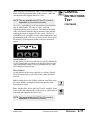
TIME SCREEN
By pressing the soft key located under the word Time on the
Main Timer Mode Screen, the preset for the timer is available. Additional information on how to access this screen can
be found in the operator display overview in Appendix E of
this manual.
CONTROL
INSTRUCTIONS
TIME SCREEN
TIME 00000.00 0 sec
Exit
The number shown is the current time preset value, i.e. the
time interval to cut the product. A cursor will appear in the
least significant digit. The user has a choice of ways to adjust
this number.
Exit or Prev, If no change is required press Exit or Prev to
return to the Main Timer Mode Screen.
Continued
UGE047/1003
CSC Servo Knife Cutters
OPERATION
4-11
CONTROL
INSTRUCTIONS
TIME SCREEN
CONTINUED
Raise will increase the preset by 0.010 second. The key can
be pressed once for each 0.010 second increment required or
held down to scroll up. Releasing the key will freeze the preset at the last value then press enter.
Lower will decrease the preset by 0.010 second. The key can
be pressed once for each 0.010 second decrement required or
held down to scroll down. Releasing the key will freeze the
preset at the last value then press enter.
Numeric keys
Key in the time required and press enter. The decimal place is
fixed so remember this when entering the preset. If you
require 1.5 seconds you must key in 1500 and then press enter.
Keying only 15 will set the time to 0.015 seconds.
Enter or Delete?
If the keyed in number is correct press the enter key for it to
be accepted and return to the Main Timer Mode screen. If it is
wrong press the delete key and the previous preset will reappear.
CONTROL
INSTRUCTIONS
HOLD-OFF
SCREEN
HOLD-OFF TIME SCREEN
By pressing the soft key located under the word Time on the
Main End Sense Mode Screen, the preset for the hold-off
timer is available. Additional information on how to access
this screen can be found in the operator display overview in
Appendix E of this manual.
Holdoff 00000.500 sec
Exit
The number shown is the current hold-off time preset, i.e. the
time interval to ignore the photo eye and avoid false cuts. A
cursor will appear in the least significant digit. The user has a
choice of ways to adjust this number.
Exit or Prev, If no change is required press Exit or Prev to
return to the Main End Sense Mode Screen.
Continued
4-12
OPERATION
CSC Servo Knife Cutters
UGE047/1003
Raise will increase the preset by 0.010 second. The key can
be pressed once for each 0.010 second increment required or
held down to scroll up. Releasing the key will freeze the preset at the last value then press enter.
Lower will decrease the preset by 0.010 second. The key can
be pressed once for each 0.010 seconds decrement required or
held down to scroll down. Releasing the key will freeze the
preset at the last value then press enter.
CONTROL
INSTRUCTIONS
HOLD-OFF
SCREEN
CONTINUED
Numeric keys
Key in the time required and press enter. The decimal place is
fixed so remember this when entering the preset. If you
require 1.000 seconds you must key in 1000 and then press
enter. Keying only 1 will set the time to 0.001 seconds and an
error message will be displayed.
Enter or Delete?
If the keyed in number is correct press the enter key for it to
be accepted and return to the Main End Sense Mode screen. If
it is wrong press the delete key and the previous preset will
reappear.
BLADE SPEED SCREEN
By pressing the soft key located under the word Blade or
Speed depending on the current mode, the preset for that
modes blade speed is available. Additional information on
how to access this screen can be found in the operator display
overview in Appendix E of this manual.
SPEED 0750.0 rpm
Exit
CONTROL
INSTRUCTIONS
BLADE SPEED
SCREEN
The number shown is the active modes current blade speed
preset, i.e. the speed the blade will pass through the part. A
cursor will appear in the least significant digit. The user has a
choice of ways to adjust this number.
Exit or Prev, if no change is required press Exit or Prev to
return to the Blade Select or Main Mode Screen.
Continued
UGE047/1003
CSC Servo Knife Cutters
OPERATION
4-13
CONTROL
INSTRUCTIONS
BLADE SPEED
SCREEN
CONTINUED
Raise will increase the preset by 1.0. The key can be pressed
once for each 1.0 increment required or held down to scroll
up. Releasing the key will freeze the preset at the last value
then press enter.
Lower will decrease the preset by 1.0. The key can be pressed
once for each 1.0 decrement required or held down to scroll
down. Releasing the key will freeze the preset at the last value
then press enter.
Numeric keys
Key in the time required and press enter. The decimal place is
fixed so remember this when entering the preset. If you
require 750.0 rpm you must key in 7500 and then press enter.
Keying only 750 will set the speed to 075.0 rpm and an error
message with the valid range will be displayed.
Enter or Delete?
If the keyed in number is correct press the enter key for it to
be accepted and return to the Blade Select or Main Mode
Screen. If it is wrong press the delete key and the previous
preset will reappear.
CONTROL
INSTRUCTIONS
BLADE COUNT
SCREEN
BLADE COUNT SCREEN
By pressing the soft key located under the word Blade or
Count depending on the current mode, the preset for the blade
count is available. Additional information on how to access
this screen can be found in the operator display overview in
Appendix E of this manual.
RUN 1 BLADES
Exit
The number shown is the current blade count preset, i.e. the
number of blades mounted to the cutter head. A cursor will
appear in the least significant digit. The user has a choice of
ways to adjust this number.
Exit or Prev, if no change is required press Exit or Prev to
return to the Blade Select or Main Mode Screen.
Continued
4-14
OPERATION
CSC Servo Knife Cutters
UGE047/1003
Raise will increase the preset by 1. The key can be pressed
once for each 1 increment required or held down to scroll up.
Releasing the key will freeze the preset at the last value then
press enter.
Lower will decrease the preset by 1. The key can be pressed
once for each 1 decrement required or held down to scroll
down. Releasing the key will freeze the preset at the last value
then press enter.
CONTROL
INSTRUCTIONS
BLADE COUNT
SCREEN
CONTINUED
Numeric keys
Key in the number of blades mounted and press enter. If the
value entered is out of range an error message with the valid
range will be displayed.
Enter or Delete?
If the keyed in number is correct press the enter key for it to
be accepted and return to the Blade Select or Main Mode
Screen. If it is wrong press the delete key and the previous
preset will reappear.
FUNCTION AREAS
Additional information on how to access and navigate these
screens can be found in the operator display overview section
of this manual.
SELECT FUNCTION >
Blade
Test
Mode
CONTROL
INSTRUCTIONS
FUNCTION
AREAS
Menu fixed function key is used to access the Function Areas
from any main mode screen. There are two Function Area
screens. The user can toggle between the two screens with the
Next and Prev fixed function keys.
< SELECT FUNCTION
Min
Parts
CPM
Continued
UGE047/1003
CSC Servo Knife Cutters
OPERATION
4-15
CONTROL
INSTRUCTIONS
FUNCTION
AREAS
CONTINUED
Next or Prev, Pressing Next selects the second Function Area.
Pressing Prev returns the display to the first Function Area
screen. Pressing Prev from the first Function Area screen
returns the display to the active main mode screen.
Menus are a convenient way to access and monitor parameters
that do not need to be altered often, i.e. blade speed, blade
count, cut mode, repeatability test, min allowable measurement and cuts per minute.
The most frequently used functions for a certain cutting mode
are directly available from the main screen for the active
mode. For a guide to screen navigation for any active mode
see the operator display overview section of this manual for
that mode. For information on the Blade and Parts Softkeys
see their respective sections covered earlier in this manual.
CONTROL
INSTRUCTIONS
TEST
TEST SOFTKEY
Pressing soft key two located under the word Test on the first
Function area screen, selects the repeatability tester.
Off
DevCP 000.000 mS >
Exit
Reset
The DevCP repeatability tester displays total deviation time in
milliseconds. This time is from a cut being requested until the
blade reaches the part. The smallest measured value is subtracted from the largest measured value and the resulting deviation is displayed on the screen. New data is sampled every
consecutive cut. The DevCP repeatability test is available in
all on-demand modes. This test is used as a tool for verifying
the accuracy of the cutter.
On/Off Softkey1
On the display, on the lower left side is a soft key labeled On
or Off. Pressing this key while On is displayed will reset all
values and disable testing. Likewise pressing this key while
Off is displayed starts the test.
Reset Softkey3
On the display, on the lower right side is a soft key labeled
Reset. Pressing this key will reset all test values and start a
new test.
Exit or Prev, Pressing Exit, Prev or the Softkey under the
word Exit resets all values and disables testing then returns the
display to the Function area screen.
Continued
4-16
OPERATION
CSC Servo Knife Cutters
UGE047/1003
Next, Pressing Next selects the DevCC test if available. If the
arrow on the top right hand side of the screen is visible the
current mode also supports the DevCC test.
NOTE: The test available DevCP, DevCC or both is
dependent on the active cut mode.
The DevCC repeatability tester also displays total deviation
time in milliseconds. This time is from a cut being
requested until the next cut request. The smallest measured
value is subtracted from the largest measured value and the
resulting deviation is displayed on the screen. The DevCC
repeatability test is available in some on-demand modes. and
all continuous modes. This test is used as a tool for verifying
the accuracy of the upstream puller or the precision timer
option.
Off
CONTROL
INSTRUCTIONS
TEST
CONTINUED
< DevCC 000.000 mS
Exit
Reset
On/Off Softkey1
On the display, on the lower left side is a soft key labeled On
or Off. Pressing this key while On is displayed will reset all
values and disable testing. Likewise pressing this key while
Off is displayed starts the test.
Reset Softkey3
On the display, on the lower right side is a soft key labeled
Reset. Pressing this key will reset all test values and start a
new test.
Exit, Pressing Exit or the Softkey under the word Exit resets
all values, disables testing then returns the display to the
Function area screen.
Prev, Pressing Prev selects the DevCP test if available. If the
arrow on the top left hand side of the screen is visible the current mode also supports the DevCP test.
NOTE: The test available DevCP, DevCC or both is
dependent on the active cut mode.
UGE047/1003
CSC Servo Knife Cutters
OPERATION
4-17
CONTROL
INSTRUCTIONS
CUT MODE
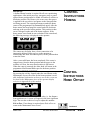
Mode Softkey
By pressing the soft key located under the word Mode, the different Cut Modes are available. There are two Cut Mode
screens. The first screen provides choices for the standardmodes available on all cutters.
SELECT CUT MODE >
Encdr
Sense
FlyWhl
The second screen displays choices for optional cut modes.
The user can toggle between the two screens with the Next
and Prev fixed function keys. Additional information on how
to access these screens can be found in the function area of the
operator display overview section of this manual.
< SELECT CUT MODE
Timer
Follwr
Auto
Press the Softkey located under the cut mode desired to select
that mode. If the mode is available an acknowledgment will be
displayed.
CUT MODE SET TO
** MODE SELECTED **
This message will be displayed for 3 seconds or until any key
is pressed.
Next or Prev, Pressing Next selects the second Cut Mode
Area. Pressing Prev returns the display to the first Cut Mode
Area. Pressing Prev from the first Cut Mode Area screen
returns the display to the Function Area screen.
4-18
OPERATION
CSC Servo Knife Cutters
UGE047/1003
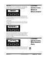
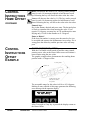
Min Softkey
By pressing the soft key located under the word Min on the
second Function Area Screen, the Minimum allowable measurement value is displayed. The active mode and the
CURRENT MIN TIME
IS 00000.150 sec.
CONTROL
INSTRUCTIONS
MINIMUM
MEASUREMENT
cuts per minute limit for the model of cutter determines the
actual value displayed. The screen will be displayed for 15
seconds or until any key is pressed, then return to the second
Function Area screen.
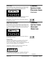
CPM Softkey
By pressing the soft key located under the word CPM on the
second Function Area Screen, the calculated cuts per minute
are displayed.
THE CURRENT SETTINGS
PRODUCE 0000.000 cpm
The active mode, measurement value, blade speed, number of
blades and line speed may all contribute to determining the
actual value displayed. The screen will be displayed for 15
seconds or until any key is pressed, then return to the second
Function Area screen.
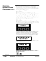
CONTROL
INSTRUCTIONS
MAINTENANCE
AREA
MAINT. AREA
SELECT MENU AREA
Maint.
Factory
Menu function key is used from the first Function Area screen
to access the Maintenance area. There are two menus Maint.
and Factory, with access via password to various sub-menus.
UGE047/1003
CSC Servo Knife Cutters
OPERATION
4-19
CONTROL
INSTRUCTIONS
ENCODER AREA
Menus are a convenient way to access and monitor parameters
that do not need to be altered often, i.e. home position,
encoder direction, scale or unit of measure. In addition, preventive maintenance parameters can be monitored for trouble
shooting and scheduling purposes.
Factory Softkey
This area is password protected for factory use only.
Please do not attempt to get around the password protection as
parameters beyond this point are used for calibration and
setup. These parameters should only be modified by trained
personal. Improper settings will reduce the performance and
possibly cause severe damage to your machine.
Maint. Softkey
Located under the word Maint. is the Maintenance soft key.
The Maintenance area is password protected. This area should
only be accessed by qualified personal. After
ENTER PASSWORD
****
pressing the Maintenance Softkey, the password entry screen
is displayed. With the numeral keys press 6 2 0 9 then the
Enter key to access the maintenance area. An improper password will cause this message to be displayed for 3 seconds.
THE PASSWORD ENTERED
WAS INCORECT!
There are three sub-menus, Encdr, Home, and P/M accessible
in the maintenance area.
SELECT MAINT. AREA
Encdr
Home
P/M
Exit or Prev, Pressing Exit or Prev will return the display to
the Menu Area screen.
Continued
4-20
OPERATION
CSC Servo Knife Cutters
UGE047/1003
Encdr Softkey
By pressing the soft key located under the word Encdr on the
Maint. Area Screen, there are three sub-menus, Drctn, U/M,
and Scale accessible. Additional information on how
SELECT ENCODER AREA
Drctn
U/M
Scale
CONTROL
INSTRUCTIONS
ENCODER AREA
CONTINUED
to access this screen can be found in the Maintenance Area of
the operator display overview section of this manual.
Exit or Prev, Pressing Exit or Prev will return the display to
the Maint. Area screen.
DIRECTION SOFTKEY
By pressing the soft key located under the word Dirctn on the
Encdr. Area Screen, the direction of the encoder rotation can
be changed. Located on the lower left side of the display is the
status text (INCORRECT/CORRECT) for the encoder direction.
COUNT DIRECTION IS
INCORRECT
Change
CONTROL
INSTRUCTIONS
ENCODER
DIRECTION
Exit or Prev, Pressing Exit or Prev will return the display to
the Encoder Area screen.
Change Softkey
With the machine stopped, by pressing the soft key located
under the word Change. The direction of the encoder is
reversed. After the change if the count direction is positive, the
status text will now display the word CORRECT.
Attempting to change the encoder direction with the cutter
running will result in the following message.
THE CUTTER MUST BE
STOPPED TO CHANGE!
This message will be displayed for 3 seconds or until any key
is pressed. Press stop on the operator panel then try again.
Continued
UGE047/1003
CSC Servo Knife Cutters
OPERATION
4-21
CONTROL
INSTRUCTIONS
ENCODER DIRECTION
CONTINUED
CONTROL
INSTRUCTIONS UNIT
OF MEASURE
If a negative symbol is shown to the left of the count value on
the main mode screen the encoder signal is reversed, i.e. rotating in the wrong direction. The Cutter will not function while
the encoder is going negative. The Direction function corrects
this by changing what the servo drive interprets as a positive
direction, CW or CCW rotation.
UNIT OF MEASURE SOFTKEY
By pressing the soft key located under the word U/M on the
Encoder Area screen, the Eng. Units can be set.
SEL. UNIT OF MEASURE
in.
Exit
mm.
Exit or Prev, Pressing Exit or Prev will return the display to
the Encoder Area screen.
in./mm. Softkeys
Pressing the soft key located under in. or mm. Changes all displayed measurements to the respective unit of measure.
The scaled distance must now be set for the desired unit. See
the Scale Area Dist. Softkey description.
Scale Softkey
By pressing the soft key located under the word Scale on the
Encoder Area Screen, there are two sub-menus, Dist., and
Counts accessible. Additional information on how to access
this screen can be found in the Maintenance Area of the operator display overview in Appendix E of this manual.
SELECT SCALE AREA
Dist.
Exit
Counts
Exit or Prev, Pressing Exit or Prev will return the display to
the Encoder Area screen.
SETTING THE SCALE FACTOR
The Encoder mode uses a scale factor to compensate for configurations that differ from the standard (a measuring wheel
with a 1 foot circumference; a 3000 pulse encoder; and
English units of measure). The prescale value is set at the factory for your equipment and typical unit of measurement.
However, it may occasionally be necessary to adjust the
prescale value.
4-22
OPERATION
CSC Servo Knife Cutters
UGE047/1003
DISTANCE SOFTKEY
By pressing the soft key located under the word Dist. on the
Scale Value Screen, the scaled distance is available. This value
must be set after a U/M change. Additional information on
how to access this screen can be found in the Maintenance
Area of the operator display overview in Appendix E of this
manual.
CONTROL
INSTRUCTIONS
SCALE
DISTANCE
ENTERDISTANCE
DISTANCEPER
PER
ENTER
COUNTS
COUNTS12.00
12.0000 in.
in.
The number shown is the current distance value, i.e. the circumference of the measuring wheel or distance per revolution
of the encoder. A cursor will appear in the least significant
digit.
Exit or Prev- if no change is required press Exit or Prev to
return to the Scale Value screen.
Raise will increase the value by 0.001inches. The key can be
pressed once for each 0.001inch increment required or held
down to scroll up. Releasing the key will freeze the value at
the last value.
Lower will decrease the value by 0.001inches. The key can be
pressed once for each 0.001inch decrement required or held
down to scroll down. Releasing the key will freeze the value
at the last value.
Numeric keys
Key in the distance desired and press enter. The decimal place
is fixed so remember this when entering the value. If you
require 12.000 inches you must key in 12000 and then press
enter. Keying only 12 will set the distance to 0.012 inches.
Enter or Delete?
If the keyed in number is correct press the enter key for it to
be accepted and return to the Scale Value screen. If it is wrong
press the delete key and the previous value will reappear.
UGE047/1003
CSC Servo Knife Cutters
OPERATION
4-23
CONTROL
INSTRUCTIONS
SCALE COUNTS
COUNTS SOFTKEY
By pressing the soft key located under the word Counts on the
Scale Value Screen, the scaled counts are available. Additional
information on how to access this screen can be found in the
Maintenance Area of the operator display overview in
Appendix E of this manual.
12.000 in. EQUALS
12000 COUNTS
The number shown is the current count value, i.e. the pulses
per revolution of the encoder. For example a 3000 pulse quadrature encoder will produce 3000 x 4 channels or 12000
counts. A cursor will appear in the least significant digit. The
user has a choice of ways to adjust this number.
Exit or Prev, if no change is required press Exit or Prev to
return to the Scale Value screen.
Raise will increase the value by 1. The key can be pressed
once for each 1 increment required or held down to scroll up.
Releasing the key will freeze the value at the last value.
Lower will decrease the value by 1. The key can be pressed
once for each 1 decrement required or held down to scroll
down. Releasing the key will freeze the value at the last value.
Numeric keys
Key in the count desired and press enter. If you require 12000
counts you must key in 12000 and then press enter.
Enter or Delete?
If the keyed in number is correct press the enter key for it to
be accepted and return to the Scale Value screen. If it is wrong
press the delete key and the previous value will reappear.
4-24
OPERATION
CSC Servo Knife Cutters
UGE047/1003
HOMING
A defined Home location is required for all servo-positioning
applications. After initial power up, emergency stop or guard
opened, home position must be found. All motion is relative to
this home position. The Home cycle occurs once after power
is applied to the servo drive in response to the Start push button being pressed. The cutter head rotates towards the home
sensor at the programmed On-Demand blade speed. After the
home sensor has been found, the cutter head will decelerate
and stop at the specified offset position. This position is then
set to 0.0 degrees at the end of the home sequence. If the
home sensor is not found in one revolution of the cutter head,
the following message is displayed on the operator.
CONTROL
INSTRUCTIONS
HOMING
HOME ROUTINE FAILED
PLEASE CHECK SENSOR!
The sensor may be faulty, have a loose connection or be
improperly adjusted. Press any key on the operator to
acknowledge the fault. Disconnect power, fix the problem then
restart the cutter.
After a successful home has been completed, if the cutter is
stopped away from the home position and the power to the
machine is left on, the cutter head position is still known.
When the cutter is restarted, the cutter head will return at the
programmed On-Demand blade speed to the home position.
HOME OFFSET SCREEN
By pressing the soft key located under the word Home on the
Maintenance Screen, the offset for the home position is available. Additional information on how to access this screen can
be found in the Maintenance Area of the operator display
overview in Appendix E of this manual.
CONTROL
INSTRUCTIONS
HOME OFFSET
OFFSET +15. 0 Deg
Exit
The number shown is the current offset value, i.e. the distance
from position zero. A cursor will appear in the least significant
digit. The user has a choice of ways to adjust this number.
Exit or Prev, If no change is required press Exit or Prev to
return to the Maintenance Area screen.
UGE047/1003
CSC Servo Knife Cutters
Continued
OPERATION
4-25
CONTROL
INSTRUCTIONS
HOME OFFSET
CONTINUED
Raise will increase the value by 1.0. The key can be pressed
once for each 1.0 increment required or held down to scroll
up. Releasing the key will freeze the value at the last value.
Lower will decrease the value by 1.0. The key can be pressed
once for each 1.0 decrement required or held down to scroll
down. Releasing the key will freeze the value at the last value.
Numeric keys
Key in the distance desired and press enter. The decimal place
is fixed so remember this when entering the value. If you
require 15.0 degrees you must key in 150 and then press enter.
Keying only 15 will set the distance to 01.5 degrees.
Enter or Delete?
If the keyed in number is correct press the enter key for it to
be accepted and return to the Maintenance Area screen. If it is
wrong press the delete key and the previous value will reappear.
CONTROL
INSTRUCTIONS
OFFSET
EXAMPLE
HOME OFFSET EXAMPLE
With the Cut Enable on/off turned off and the cutter started,
entering a new value at the Home Offset screen will initiate a
home routine using the new value.
The graphic example above demonstrates the resulting home
position with a 15 degree offset.
+15.0 Deg. Offset
Center of cut
180 Deg. from the center
of the cut is the relative
zero position.
The acceptable range for this value is 00.0 to +45.0 degrees.
Making an entry outside of this range generates the following
error message on the operator display.
HOME OFFSET RANGE IS
00.0 TO +45 Deg.
After 5 seconds or if any key is pressed the display returns to
the Home Offset
4-26
OPERATION
CSC Servo Knife Cutters
UGE047/1003
PREVENTIVE MAINTENANCE SOFTKEY
Pressing the soft key located under the word P/M on the
Maint. area screen. Selects the P/M area screen. Three preventive maintenance sub-menus for monitoring Inputs, Time
and Cycles are displayed.
CONTROL
INSTRUCTIONS
PREVENTIVE
MAINTENANCE
SELECT P/M AREA
Inputs
Time
Cycles
Additional information on how to access this screen can be
found in the Maintenance Area of the operator display
overview in Appendix E of this manual.
Inputs Softkey
Pressing the soft key located under the word Inputs on the
P/M area screen, selects the inputs monitoring screen.
I1=Off I2=Off I3=Off
I4=On I5=On I6=Off
This screen displays the cutters input status. Active inputs are
equal to On and de-energized inputs are equal to Off. This
information could be used for trouble shooting with out the
use of a meter.
Input #1 = End Sense Trigger when On
Input #2 = Run when Off
Input #3 = Manual Cut Trigger when On
Input #4 = Home Registration when On
Input #5 = E-Stop when Off
Input #6 = Spare
Exit or Prev, Pressing Exit or Prev returns the display to the
Select P/M area screen.
UGE047/1003
CSC Servo Knife Cutters
OPERATION
4-27
CONTROL
INSTRUCTIONS
POWER ON TIME
TIME SOFTKEY
Pressing the soft key located under the word Time on the
P/M area screen, selects the power-on time screen.
POWER ON 00000.0 Hrs
Exit
The Power-On time screen displays the total time in hours
that the machine has had the power switched on. This information could be used for scheduling preventive maintenance.
The displayed time can not be reset.
Exit or Prev, Pressing Exit, Prev or the Softkey under the
word Exit returns the display to the Select P/M area screen.
Cycles Softkey
Pressing the soft key located under the word Cycles on the
P/M area screen, selects the machine cycles screen.
MACH.CYCLES 00000000
Exit
The Machine Cycles screen displays the absolute total cuts
that the machine has made since manufacture. This information could be used for scheduling preventive maintenance.
The displayed count can not be reset.
Exit or Prev, Pressing Exit, Prev or the Softkey under the
word Exit returns the display to the Select P/M area screen.
4-28
OPERATION
CSC Servo Knife Cutters
UGE047/1003
1
Press the manual cut button and observe the
movement of the cutter blade. The cutter head makes a
single rotation and the blade moves through the cutter
bushings without interference.
2
Insert a piece of extrudate through the cutter bushings.
3
Press the manual cut button. A single cut is made
CHECKING CUT
QUALITY
at the preset blade speed. (This works even if Cut On/Off
is off.)
4
Inspect the cut. If necessary, adjust the blade design
or blade speed. See, All About Cutter Blades, Appendix
B.
If you have not already done so, check the cutter hardware,
power up the cutter, select cutting mode and blade speed, and
make a test cut to check cut quality.
STARTING THE
SERVO CUTTER
When you are satisfied with cut quality, press the Cut On/Off
soft key and on is displayed, automatic operation begins.
When the extrudate is running within tolerance, cut it with a
knife or saw and feed it through the cutter bushings.
UGE047/1003
CSC Servo Knife Cutters
OPERATION
4-29
MAKING
ADJUSTMENTS
DURING
OPERATION
There are several adjustments you can make during
normal cutting. These adjustments include:
● In Timer mode, adjust the time between cuts
● In Encoder and Follower modes, adjust the
length
● In Product mode, adjust the hold-off time
● In Flywheel mode, adjust blade speed (CSC only)
● Adjust blade speed in all modes except
Follower
● Perform a manual cut and reset the length by
pressing the manual cut button at any time during
on-demand cutting. Pressing Reset/Test has no
effect during continuous cutting.
● Count the total number of cuts by pressing the
Total On/Off soft key. Use the Reset button to
return the count to zero. This feature is useful for
collecting samples during a production run.
● Count the batches of cuts by pressing the Total
On/Off soft key. Use the Reset button to return the
count to zero. This feature is useful for collecting
samples during a production run.
● Stop cutting temporarily by setting Cut On/Off
to off. This allows you to view the cutting blade
(through the window) or perform other tasks without shutting down the cutter.
NOTE: While the controller will allow you to
switch modes during operation, this is not
recommended.
4-30
OPERATION
CSC Servo Knife Cutters
UGE047/1003
WARNING: Never stop the servo cutter by opening the knife guard.
This can cause damage to the equipment and
injury to personnel.
STOPPING THE
SERVO CUTTER
Use this procedure to safely stop the servo cutter:
1
2
3
Press Cut On/Off soft key to stop cutting (soft key
text changes to off).
Press Stop Cutter button to disable the servo motor
(start light is off).
Turn the rotary disconnect to the off position.
WARNING: Never turn off the rotary
disconnect first.
Doing so will turn off all power to the unit, and
the cutter will not be brought to a controlled
stop. For safe stopping, always follow the
sequence given above.
4
Disconnect the power cord if it is equipped with
5
6
Lock out the rotary disconnect.
a plug on the end.
Clean the lubricant reservoir if you are shutting
the servo cutter down for the day.
UGE047/1003
CSC Servo Knife Cutters
OPERATION
4-31
MAINTENANCE
● Maintenance Features . . . . . . . .5-2
● Warnings and Cautions . . . . . . .5-2
● Maintenance Overview . . . . . . .5-4
● Preventative Maintenance
Schedule . . . . . . . . . . . . . . . . .5-4
● Checking the Blades . . . . . . . . .5-6
● Inspecting Cutter
Bushing Screws . . . . . . . . . . .5-7
● Checking the Closure Latch . . .5-7
● Cleaning the Blade Tray . . . . . . .5-8
● Lubricating the Slide
Rail System . . . . . . . . . . . . . . .5-8
● Adjusting the
Proximity Switches . . . . . . . . .5-9
● Checking Electrical
Connections . . . . . . . . . . . . .5-10
● Checking Torque . . . . . . . . . . .5-12
UGE047/1003
CSC Servo Knife Cutters
5-1
MAINTENANCE
FEATURES
The Servo Cutter CSC models need regular, scheduled maintenance for peak performance. Among the features that
require maintenance are:
● Cutter blades
● Blade mounting hardware
● Cutter bushings
● The knife guard hardware
● Cutter alignment
● Floor locks
● Lubrication tray
● Shafts of optional slide rail system
● Electrical cables
● Control panel lights
WARNINGS
CAUTIONS
AND
To maintain the best performance of the servo cutter, it must
be cleaned and inspected regularly. Maintenance includes a
daily, weekly, quarterly, and semi-annual (every 6 months)
schedule.
Use this maintenance schedule as a guide. You may need to
shorten the time of the maintenance schedule, depending on
how often you use the servo cutter, and the types of material
flowing through it.
Follow all precautions and warnings when working on the
equipment.
WARNING: Improper installation,
operation, or servicing may result in
equipment damage or personal injury.
This equipment should only be installed, adjusted, and serviced by qualified technical personnel who are familiar with the construction, operation, and potential hazards of this type of
machine.
All wiring, disconnects, and fuses should be
installed by qualified electrical technicians in
accordance with electrical codes in your region.
5-2
MAINTENANCE
CSC Servo Knife Cutters
UGE047/1003
WARNING: Voltage Hazard
This equipment is powered by alternating current, as specified on the machine serial tag and
data plate. Do not operate the equipment at
power levels other than what is specified on the
machine serial tag and data plate.
A properly-sized conductive ground wire from
the incoming power supply must be connected
to the chassis ground terminal inside the electrical enclosure. Improper grounding can result in
severe personal injury and erratic machine
operation.
LOCKOUT/TAGOUT:
Before performing maintenance or repairs on
this product, disconnect and lock out electrical
power sources to prevent injury from unexpected energization or start-up. A lockable disconnect device has been provided to isolate this
product from potentially hazardous electricity.
DANGER: Sharp blades!
Most injuries caused by knife blades occur
when the cutter has been turned off. Handle
blades with care at all times.
● Always wear cut-resistant gloves when the
cutting chamber is open and when handling
blades.
● Always lock out the cutter before opening the
cutting chamber. (See Lockout/tagout above)
● Always wait until the cutter head has stopped
completely before opening the knife guard.
CSC cutters are equipped with several safety
devices to ensure safe operation. Never remove
or disable these devices to sustain production.
Operating without these devices can cause
severe injury.
● When the knife guard is opened, the knife
guard switch stops the cutter.
● Two proximity-type safety switches prevent
operation unless the cutter bushings are in
place.
● The STOP button activates a circuit that
stops the knife.
UGE047/1003
CSC Servo Knife Cutters
MAINTENANCE
5-3
MAINTENANCE
OVERVIEW
This section describes the daily, weekly, monthly and semiannual maintenance schedules that should be performed when
changing materials or lines, or when changing equipment, as
well as the maintenance procedures to follow.
Cutting either flexible or rigid materials generates tremendous
shock and vibration to the entire unit. Anything that can
loosen, will over time.
To maintain the best performance, follow this maintenance
schedule and develop an effective preventative maintenance
program.
PREVENTATIVE
MAINTENANCE
SCHEDULE
5-4
MAINTENANCE
● Daily
❒ Checking cutter blade(s)
Clean, sharpen or replace as needed (see Checking the
Blades, Section 5).
❒ Inspecting the blade mounting hardware
The blade securing bolt should use both a lock washer
and flat washer, and be tightened enough to fully compress the lock washer. Replace the holding pins if they
appear worn.
❒ Inspecting the cutter bushing screws
Check that the cutter bushing screws are secure (see
Inspecting Cutter Bushing Screws, Section 5).
❒ Checking the closure latch on the knife guard
(See Checking the Closure Latch, Section 5).
❒ Inspecting cutter alignment
Proper cutter alignment is critical for optimum performance. Use a plumb line or laser to check for a
straight line from the extrusion die to the cutter bushings.
❒ Check floor locks
It is always recommended that the weight be removed
from the casters for optimum stability during cutting
cycles. Check to see if the floor locking mechanism is
properly adjusted.
CSC Servo Knife Cutters
UGE047/1003
● Weekly
❒ Cleaning the blade lubrication tray
(See Cleaning the Blade Tray, Section 5).
❒ Lubricating shafts on optional slide rail system
(See Lubricating the Slide Rail System, Section 5).
● Monthly
❒ Checking hardware on the knife guard
Inspect the hardware on the knife guard (fasteners on
hinge and the clear blade guard window). Tighten as
needed.
❒ Checking bushing holder proximity switches
Inspect the sets screws which retain the bushing holder
proximity switches for tightness. Adjust as needed.
(See Adjusting the Proximity Switches, Section 5).
PREVENTATIVE
MAINTENANCE
SCHEDULE
CONTINUED
❒ Checking the metal draw latch
Inspect the latch on knife guard for wear and proper
tension. Readjust or replace as needed.
❒ Clean the clear blade guard window
Clean using glass cleaner or plain water. Other materials may cause premature loss of clarity or crazing.
● Semi-annual (every 6 months)
❒ Inspecting electrical terminals
Check all electrical terminals for tightness; adjust as
needed. (See Checking Electrical Connections, Section
5).
❒ Checking torque on Trantorque coupling device
Check the tightness (torque) of the Trantorque coupling
device with a torque gauge. This device connects the
cutter head to the Micron reducer shaft. (See Checking
Torque, Section 5).
❒ Checking all electrical cables
Inspect all electrical cables for cuts and abrasions.
Replace as needed.
❒ Inspecting control panel lights
Check to make sure no LEDs or lights are burned out
on the control panel. Replace as needed.
UGE047/1003
CSC Servo Knife Cutters
MAINTENANCE
5-5
CHECKING
BLADES
Blades become dull over time depending on the material being
cut, cut rate, blade speed, and blade material and thickness.
Check blades regularly for sharpness as well as scratches,
nicks, burrs, and material buildup. Clean, sharpen or replace
as needed (see Installing Cutter Blades, Section 3).
DANGER: Sharp blades!
Most injuries caused by knife blades occur
when the cutter has been turned off. Handle
blades with care at all times.
● Always wear cut-resistant gloves when the
cutting chamber is open and when handling
blades.
● Always lock out the cutter before opening the
cutting chamber.
● Always wait until the cutter head has stopped
completely before opening the knife guard.
CSC cutters are equipped with several safety
devices to ensure safe operation. Never remove
or disable these devices to sustain production.
Operating without these devices can cause
severe injury.
● When the knife guard is opened, the knife
guard switch stops the cutter.
● Two proximity-type safety switches prevent
operation unless the cutter bushings are in
place.
● The STOP button activates a circuit that
stops the knife.
5-6
MAINTENANCE
CSC Servo Knife Cutters
UGE047/1003
Check the set screws that secure the cutter bushings. If bushings move during cutting, cutting blades and possibly the
drive chain could be damaged.
Check the latch and adjust it so the knife guard closes completely. This prevents false triggering of the safety switch.
UGE047/1003
CSC Servo Knife Cutters
INSPECTING
CUTTER
BUSHING
SCREWS
CHECKING THE
CLOSURE
LATCH
MAINTENANCE
5-7
CLEANING THE
BLADE TRAY
This tray is built into the cutter assembly as a simple method
of applying lubrication to your blade during cutting cycles.
Depending on cut rate and type of material and lubrication,
the area will need to be cleaned on a regular basis and the
lubricant replaced. Open the knife guard and, using a shop vac
or other similar equipment, remove all liquid and solids from
the cutting chamber and around the bushings. Replace the
lubricant. For more information, see the Appendix D, Blade
and Bushing Lubrication.
Lubricant Tray
LUBRICATING
THE SLIDE RAIL
SYSTEM
5-8
MAINTENANCE
Check the shafts on the slide rail system. Even though these
shafts are stainless steel, it is recommended that a light oil
(WD-40 or similar) be applied to the shafts as needed. Wipe
off any excess.
CSC Servo Knife Cutters
UGE047/1003
Follow all warnings and cautions listed at the beginning of the
Maintenance section of this User Guide.
1
Be sure the main power is disconnected and the
cutter is locked out.
2
Loosen the set screws that hold the cutter bushings.
3
Remove the cutter bushings.
4
Check the depth of the proximity switch
ADJUSTING THE
PROXIMITY
SWITCHES
face for each bushing. It should be recessed no more than
0.010 inches, but should not interfere with the bushings
themselves.
5
Use an Allen wrench to check the tightness
of each proximity switch's retaining screw.
NOTE: You can damage the proximity switch if you
over-tighten the retaining screw.
6
Replace cutter bushings and check for proper cutting blade alignment. (See Mounting the Cutter Bushings,
Section 3 and Appendix C).
7
Plug in the power cord and turn the main power disconnect to the on position if all other maintenance is completed.
UGE047/1003
CSC Servo Knife Cutters
MAINTENANCE
5-9
CHECKING
ELECTRICAL
CONNECTIONS
WARNING: Electrical hazard
Before performing any work on this product,
disconnect and lock out electrical power
sources to prevent injury from unexpected energization or start-up. A lockable device has been
provided to isolate this product from potentially
hazardous electricity.
WARNING: Improper installation, operation, or servicing may result in
equipment damage or personal injury.
This equipment should only be installed, adjusted, and serviced by qualified technical personnel who are familiar with the construction, operation, and potential hazards of this type of
machine.
All wiring, disconnects, and fuses should be
installed by qualified electrical technicians in
accordance with electrical codes in your region.
Always maintain a safe ground. Do not operate
the equipment at power levels other than what
is specified on the machine serial tag and data
plate.
1
Be sure the main power is disconnected and
the cutter is locked out. Always disconnect and
lock out the main power source before opening the unit or
servicing.
2
Turn the main power disconnect to the off
position before opening the electrical enclosure on the
back of the cutter, or the back of the control. This is a
safety device to prevent you from opening the doors if the
power is still on.
Main power
safety disconnect
Continued
5-10
MAINTENANCE
CSC Servo Knife Cutters
UGE047/1003
3
4
Open the electrical enclosure.
Inspect all wires and connections. Look for loose
wires, burned contacts, and signs of over-heated wires.
Have a qualified electrician make any necessary repairs or
replacements.
5
6
CHECKING
ELECTRICAL
CONNECTIONS
CONTINUED
Close the electrical enclosure door.
Inspect the exterior power cords. Cords should
not be crimped, exposed, or rubbing against the frame. If
the main power cord runs along the floor, make sure it is
not positioned where it could rest in pooling water or
could be run over and cut by wheels or casters.
UGE047/1003
CSC Servo Knife Cutters
MAINTENANCE
5-11
CHECKING
TORQUE
The Trantorque coupling device connects the servo motor to
the cutter head. It is important that it is tightened to the
proper torque.
WARNING: No lubricants!
Use no lubricants on the Trantorque coupling
device.
1
Carefully remove the cutter blade.
DANGER: Sharp blades!
Always wear cut-resistant gloves when the cutting chamber is open and when handling
blades. Never open cutting chamber without
locking out the cutter power and waiting until
the cutter head has stopped completely. Handle
blades with care at all times.
2
Check to make sure both the shaft and component bore of the Trantorque coupling device are
completely free of paint, grease, oil, and dirt. If necessary,
clean the surfaces with a non-petroleum based solvent,
such as isopropyl alcohol.
3
5-12
MAINTENANCE
Use a torque wrench to make sure the nut is tightened to the proper installation torque (2000 in-lb or
225 N-m). Do not overtighten; it can cause damage to the
unit.
CSC Servo Knife Cutters
UGE047/1003
TROUBLESHOOTING
● Before Beginning . . . . . . . . . . . .6-2
● A Few Words of Caution . . . . . .6-2
● Identifying the
Cause of a Problem . . . . . . . . .6-3
● Electrical Problems . . . . . . . . . .6-4
● Product Quality Problems . . . . .6-8
Repair
● Replacing Safety and
Proximity Switches . .
● Checking the
Servo Amplifier . . . . .
● Adjusting the
Proximity Switches . .
● Checking the Encoder .
● Checking the Motor/
Reducer Assembly . . .
● Checking Repeatability
UGE047/1003
. . . . . .6-12
. . . . . .6-12
. . . . . .6-13
. . . . . .6-14
. . . . . .6-15
. . . . . .6-16
CSC Servo Knife Cutters
6-1
BEFORE
BEGINNING
You can avoid most problems by following the recommended
installation, operation and maintenance procedures outlined in
this User Guide. If you have a problem, this section will help
you determine the cause and tell you how to fix it.
Find any wiring, parts, and assembly diagrams that were
shipped with your equipment. These are the best reference for
correcting a problem. The diagrams will note any custom features or options not covered in this User Guide.
Verify that you have all instructional materials related to the
servo knife cutter. Additional details about troubleshooting
and repairing specific components are found in these materials.
Check that you have manual for other equipment connected in
the system. Troubleshooting may require investigating other
equipment attached to, or connected with the cutter.
A FEW WORDS
OF CAUTION
WARNING: Improper installation, operation, or servicing may result in
equipment damage or personal injury.
This equipment should only be installed, adjusted, and serviced by qualified technical personnel who are familiar with the construction, operation, and potential hazards of this type of
machine.
All wiring, disconnects, and fuses should be
installed and adjusted by qualified electrical
technicians in accordance with electrical codes
in your region. Always maintain a safe ground.
Do not operate the equipment at power levels
other than what is specified on the machine
serial tag and data plate.
WARNING: Electrical hazard
Before performing maintenance or repairs on
this product, disconnect and lock out electrical
power sources to prevent injury from unexpected energization or start-up. A lockable device
has been provided to isolate this product from
potentially hazardous electricity.
6-2
TROUBLESHOOTING
CSC Servo Knife Cutters
UGE047/1003
DANGER: Sharp blades!
Most injuries caused by knife blades occur
when the cutter has been turned off. Handle
blades with care at all times.
● Always wear cut-resistant gloves when the
cutting chamber is open and when handling
blades.
● Always lock out power to the cutter before
opening the cutting chamber.
● Always wait until the cutter head has stopped
completely before opening the knife guard.
CSC cutters are equipped with several safety
devices to ensure safe operation. Never remove
or disable these devices to sustain production.
Operating without these devices can cause
severe injury.
● When the knife guard is opened, the knife
guard switch stops the cutter.
● Two proximity-type safety switches prevent
operation unless the cutter bushings are in
place.
● The STOP button activates a circuit that
stops the knife.
The Troubleshooting section covers problems directly related
to the operation and maintenance of the servo cutter. This section does not provide solutions to problems that originate with
other equipment. Additional troubleshooting help can be
found in the manufacturer’s manuals included with this User
Guide.
IDENTIFYING THE
CAUSE OF A
PROBLEM
The main problems you will see with the servo cutter are:
● Cutter operation problems, which focus on problems
that are clearly related to the operation of the cutter’s
electrical control systems.
● Plastic product quality concerns, which deal with product characteristics that may be related to cutter operation.
Of course, other sections of the extrusion line also influence the quality of the extruded product. This section
does not provide solutions to problems originating with
other equipment on the extrusion line.
UGE047/1003
CSC Servo Knife Cutters
TROUBLESHOOTING
6-3
ELECTRICAL
PROBLEMS
Look in this section when you have problems such as lights on
the control that are working improperly, buttons that do not
execute the function properly, and when information input is
not executed properly.
Symptom
Possible cause
Solution
◆ Servo drive is
The E-stop button is
pushed in.
Pull out the E-stop button.
Master safety relay not
energized
Check to see if:
without power
❒ Bushings are in place.
❒ The blade guard is closed.
❒ Master Safety relay (ISC)
has failed. Replace relay.
A safety switch has failed. Check connections and replace
if needed.
◆ Pressing Start
Cutter has no
effect. The light
does not light.
◆ Pressing the
Manual cut button
does not produce a
cut when in an ondemand mode.
6-4
TROUBLESHOOTING
There is a loose connection.
Check wiring between push
button and the relay. (ICR)
The relay is bad. (ICR)
Replace the relay.
The safety circuit failed.
Check safety circuit, repair or
replace components.
The servo amplifier
motion program not running.
There is a loose connection.
Stop then restart the cutter, if
necessary, reboot main power.
CSC Servo Knife Cutters
Check wiring between the
push button and input three on
the servo drive and tighten
connection.
UGE047/1003
ELECTRICAL
PROBLEMS
CONTINUED
Symptom
Possible cause Solution
◆ After pressing
The Blade Home proximity switch failed or the
connection to it is loose.
Check connections and replace
switch if needed.
Guard circuit is open.
Check to see if:
Start Cutter, the
cutter head rotates
and stops in wrong
position.
◆ Master safety
relay does not energize.
❒ The bushings are in place
❒ The blade guard is closed.
❒ Loose connection to guard
circuit. Tighten connection.
❒ Guard switch is bad.
Replace switch.
❒ Bussing proximity is bad
replace switch
E-stop button is pressed
◆ Measurement
display does not
change value.
UGE047/1003
❒ Pull out E-stop button
Input from encoder
failed.
Check encoder cable for continuity. Connect any loose wires.
Encoder failed.
Replace encoder.
CSC Servo Knife Cutters
TROUBLESHOOTING
6-5
ELECTRICAL
PROBLEMS
CONTINUED
Symptom
Possible cause
Solution
◆ In encoder or
There is a problem with
the servo amplifier.
See Checking the Servo
Amplifier.
There is a loose connection.
Check wiring for loose connections.
timer modes, the
display shows the
count which resets,
but a cut does not
occur at the point
of reset.
◆ Blade speed does There is a communication
Check for wiring for loose
connections and tighten.
not change when
new speed is
entered into the
control.
failure between the control and drive.
◆ Cutter mode
There is a communication Check for wiring for loose confailure between the connections and tighten.
trol and drive.
selection does not
change cut mode.
◆ The park (home) The coupling between the See Checking the Motor/
position is drifting,
i.e. the blade parks
further away from
the original park
site.
6-6
TROUBLESHOOTING
servo motor and the
Micron reducer has
slipped.
reducer assembly, page 6-15
The Trantorque coupling
has slipped.
Refer to the Trantorque instructions, page 5-12.
CSC Servo Knife Cutters
UGE047/1003
PRODUCT
QUALITY
PROBLEMS
Look in this section when the final product does not meet
standards: has strings, burrs, cracks, or is misshaped.
Symptom
Possible cause
◆ Hairs or strings. Blade speed is too low.
Solution
Increase the blade speed or
decrease the blade cut path
area (blade width)
The blade is too thick.
Excessive blade thickness can
cause frictional heat. Use a
thinner blade.
The blade is wrong for the
application.
Change angle of the blade
attack or the blade style to
decrease the cut path area.
Material is building up on Use blade lubrication (water,
the blade and wiping off on etc.) or change lubricants.
Consider a blade wiping systhe cut site.
tem.
There are imperfections on The cutting edge should not
have grind marks, burrs or
the blade.
other imperfections. Check the
blade and replace if necessary.
UGE047/1003
A hole or slot in the blade
cut path is causing a
‘cheese grater’ effect.
Change blade design.
The extrudate is too cold.
If the extrudate is too cold, it
can fracture during cutting.
Raise the extrudate's temperature.
CSC Servo Knife Cutters
TROUBLESHOOTING
6-7
PRODUCT
QUALITY
PROBLEMS
CONTINUED
6-8
Symptom
Possible cause
Solution
◆ Burrs at cut site.
The bushings are not providing enough support
during cutting.
Change bushing design to
make them more supportive.
The bushing gap is too
wide.
The bushing gap should be no
more than .001-.003 inches
larger than the blade. Check
and adjust if necessary.
The blade speed is too low.
Low blade speeds can cause
excessive blade interruption.
Increase blade speed or
decrease the blade cut path
area.
SECTION
HEAD
CSC Servo Knife Cutters
UGE047/1003
PRODUCT
QUALITY
PROBLEMS
CONTINUED
Symptom
Possible cause
◆ Cracks at cut
The extrudate is too cold. If the extrudate is too cold, it
can fracture or whiten during
cutting. Raise the extrudate's
temperature.
site.
The blade speed is too
high.
Solution
High blade speeds can cause
too much impact. Lower the
blade speed.
The bushings are not pro- Change the bushing design to
viding enough support
make them more supportive.
during cutting.
UGE047/1003
The cutting blade is too
sharp.
A blade that is too sharp can
fracture some materials, especially rigid PVC and nylons.
Slightly dull the blade.
If using Nylon, it may be
cooling too quickly.
If nylon is cooled too quickly,
its molecular structure may
become unstable, leading to
poor physical properties. Try
more gradual cooling.
CSC Servo Knife Cutters
TROUBLESHOOTING
6-9
PRODUCT
QUALITY
PROBLEMS
CONTINUED
6-10
Symptom
Possible cause
Solution
◆ Cut is not square.
The blade speed is too
low.
Low blade speeds can cause
excessive blade interruption.
Increase blade speed or
decrease the blade cut path
area.
The blade is misaligned.
Check that blade is 90 degrees
relative to the bushing holder.
The cutter bushings are
not properly gapped.
If the cutter bushings are not
properly gapped, the blade
may be free to move with the
extrudate. Check and adjust if
necessary. See Appendix A.
The knife bevel is not
symmetric.
If the knife bevel is asymmetric, the blade will tend to move
in the direction of the smaller
bevel. Be sure that the bevel is
symmetric. NOTE: You can
use this to your advantage with
some rigid products.
For rigid products the
puller is too close to the
cutter.
There must be enough space
between the puller and cutter
to allow for extrudate stoppage
that occurs during cutting.
Allow enough space so no cut
shock is detectable at the input
to the belt puller with your fingernail.
TROUBLESHOOTING
CSC Servo Knife Cutters
UGE047/1003
Three safety switches are included in CSC cutters: a keyed
safety switch on the knife guard, and a proximity switch on
each cutter bushing. A failure in any of these switches will prevent the cutter from running.
● Safety Switch
If you suspect a problem with the keyed safety switch on
the knife guard, check for loose or damaged wires. Replace
the switch if wires appear to be undamaged.
REPLACING
SAFETY AND
PROXIMITY
SWITCHES
● Proximity Switches
The proximity switches on the cutter bushings have LEDs
that light when the bushing is sensed. If an LED does not
light when both bushings are in place:
1
Check for loose or damaged wires.
2
Remove the cutter bushing and make sure the proximity switch is properly positioned, i.e. 0.010 inches
from the bushing surface.
3
Remove the proximity switch by loosening the set
screw. Test it by bringing some object close to the
sensor when the power is turned on. If the LED does
not light, replace the proximity switch.
The servo amplifier is equipped with a digital readout that can
be seen through the viewing window on the electrical enclosure. This display shows amplifier status and error messages.
Refer to the supplier's documentation included with this User
Guide.
CHECKING THE
SERVO
AMPLIFIER
NOTE: Make sure you look for servo amplifier messages
before you shut off the power, because fault
message will be lost.
UGE047/1003
CSC Servo Knife Cutters
TROUBLESHOOTING
6-11
ADJUSTING THE
PROXIMITY
SWITCHES
The home position proximity switch should be 0.010 inch
from the 5/16 inch thread rod on the cutter head for proper
operation.
1
Open the knife guard.
2
Locate the 5/16 inch thread rod on the cutter
head. It should be 0.010 inch from the proximity
switch sensor when it passes that location. If necessary,
loosen the jam nuts, readjust the distance, and re-tighten
the jam nuts.
DANGER: Sharp blades!
Always wear cut-resistant gloves when the cutting chamber is open and when handling
blades. Never open cutting chamber without
locking out the cutter power.
Most injuries caused by knife blades occur
when the cutter has been turned off. Handle
blades with care at all times.
3
6-12
TROUBLESHOOTING
If the proximity switch does not sense the cutter
head after this adjustment, remove the switch and test it
outside the cutter. Replace if necessary.
CSC Servo Knife Cutters
UGE047/1003
When the encoder is working properly, the measurement displayed will count up to the preset and reset to zero.
1
Check all connections.
2
Check the encoder cable for damage. If neces-
3
Check the connector that attaches the cable to
the encoder. Internal wiring may be shorted out if this
CHECKING THE
ENCODER
sary, replace.
connector is not handled properly.
4
Check the encoder itself. There should be no play
in the shaft.
WARNING: Delicate equipment
The encoder is a delicate piece of equipment.
Any rough handling can damage fragile parts.
5
If all else fails, contact Conair Customer Service. See
Appendix A.
UGE047/1003
CSC Servo Knife Cutters
TROUBLESHOOTING
6-13
CHECKING THE
MOTOR/REDUCER
ASSEMBLY
6-14
TROUBLESHOOTING
1
2
Open the knife guard.
3
Locate the four bolts holding the motor/reducer
4
Refer to the Micron installation and maintenance
information included with this User Guide to check and
adjust the motor/reducer assembly.
Remove the cutter head by loosening the Trantorque
assembly. Refer to the manufacturer's guide included with
this User Guide for information about the Trantorque
assembly.
assembly to the cutter. Remove them and carefully
remove the assembly from the cutter.
CSC Servo Knife Cutters
UGE047/1003
Before any Conair puller/cutters are shipped, they are tested
for cut time repeatability to be sure they are within performance specifications. The repeatability test checks the performance of the rotary knife cutter to return the home park position after a complete cut. Acceptable repeatability times
allowed for each cutter model prior to shipping are:
Type of Cutter
Repeatability Time
AC Pneumatic Cutter
DC Pneumatic Cutter
Positional Servo
Less than 1 millisecond
Less than 1.5 millisecond
Less than 0.1 millisecond
TESTING
REPEATABILITY
Note: 1-millisecond at 60 feet per minute is equal to .012 inches.
The repeatability mode is built into the Conair cutter controls
and allows you to perform similar tests, without any external
test equipment. It is recommended that you check repeatability
on a regular basis. Acceleration/deceleration delays of the
servo do not contribute to repeatability error; any error is
attributed solely to motor stability, couplings, assembly,
power, and proximity sensor alignment.
Use any blade speed and line speed. The line speed is only
seen while in the Encoder or Product modes. It is recommended that the tests be performed at cut intervals between 0.5 and
5-seconds. Do not change the blade speed or the line speed
after starting the test.
To test repeatability:
1
Turn on the cutter. Perform the test in encoder mode
with the cutter on-line. The Display will read: DevCP
shows problems with the cutter. DevCC shows problems
with the puller.
2
Press the menu key to display operator functions.
3
4
Press soft key test to display DevCP screen
5
Press soft key on/off to start the testing and display the results.
Press next key displays DevCC
results.
Note: Previous key returns to DevCP screen.
Repeat the test by pressing the Reset Cut button to begin
a new sample period.
To end the Repeatability test, press soft key on/off or exit.
UGE047/1003
CSC Servo Knife Cutters
TROUBLESHOOTING
6-15
RESULTS OF
REPEATABILITY
TESTING
Results in Flywheel mode
The display shows DevCC a full revolution of the cutter head.
The reading is in milliseconds, to the third decimal place, i.e.
0.010 is 0.01 milliseconds (or 10 microseconds). If the reading
exceeds 0.200 there is a problem with the cutter drive. If this
occurs the error is too large and there is a problem in the cutter drive that must be corrected.
Results in Timer mode
When testing repeatability in Timer mode, the cutter is making
on-demand cuts at a set time interval (i.e. one-second intervals). The display shows the cut-to-part (CP) reading and the
cut-to-cut (CC) reading. The reading is in milliseconds, to the
third decimal place, i.e. 0.010 is 0.01 milliseconds (or 10
microseconds).
CP is the peak time variance between the cut signal output
(preset time) to the servo amplifier, and the programmable
limit switch just prior to the center of the bushing. This is the
repeatability of the cutting system to accelerate through the
part. This value is higher than the CC reading since it includes
the acceleration and deceleration contributed by the servo
motor.
CC is the peak time variance between cuts. Record and compare the cut-to-cut number to the CC value recorded in
encoder or product mode shows how much error is by external
influences (i.e. variation in belt puller speed, encoder mounting problem, etc.).
If the reading exceeds 0.200, there is a problem with the cutter
drive. If this occurs the error is too large and there is a definite
problem that must be corrected.
Results in Product mode
The display shows the cut-to-part (CP) reading and the cut-tocut (CC) reading. The reading is in milliseconds, to the third
decimal place, i.e. 0.010 is 0.01 milliseconds (or 10 microseconds).
Compare the cut-to-part (CP) reading to the CP reading in the
other modes. There should be very little difference in these
readings.
Compare the cut-to-cut (CC) reading to the CC reading in the
other modes. Since the Product mode is influenced by external
signals, this reading will reflect the speed regulation of the
puller.
6-16
TROUBLESHOOTING
UGE047/1003
CSC Servo Knife Cutters
Conair has made the largest investment in customer support in
the plastics industry. Our service experts are available to help
with any problem you might have installing and operating
your equipment. Your Conair sales representative also can help
analyze the nature of your problem, assuring that it did not
result from misapplication or improper use.
To contact Customer Service personnel, call:
WE’RE HERE
TO HELP
HOW TO CONTACT
CUSTOMER
SERVICE
From outside the United States, call: 814-437-6861
You can commission Conair service personnel to provide onsite service by contacting the Customer Service Department.
Standard rates include an on-site hourly rate, with a one-day
minimum plus expenses.
If you do have a problem, please complete the
following checklist before calling Conair:
❒ Make sure you have all model, serial and parts list
numbers for your particular equipment. Service
personnel will need this information to assist you.
BEFORE YOU
CALL ...
❒ Make sure power is supplied to the equipment.
❒ Make sure that all connectors and wires within
and between the cutter and related components have
been installed correctly.
❒ Check the troubleshooting guide of this manual
for a solution.
❒ Thoroughly examine the instruction manual(s)
for associated equipment, especially controls.
Each manual may have its own troubleshooting
guide to help you.
❒ Check that the equipment has been operated as
described in this manual.
❒ Check accompanying schematic drawings for
information on special considerations.
SERVICE INFORMATION
Additional manuals and
prints for your Conair
equipment may be
ordered through the
Customer Service or
Parts Departments for
a nominal fee.
APPENDIX A-1
EQUIPMENT
GUARANTEE
PERFORMANCE
WARRANTY
Conair guarantees the machinery and equipment on this
order, for a period as defined in the quotation from date of
shipment, against defects in material and workmanship
under the normal use and service for which it was recommended (except for parts that are typically replaced after
normal usage, such as filters, liner plates, etc.). Conair’s
guarantee is limited to replacing, at our option, the part or
parts determined by us to be defective after examination.
The customer assumes the cost of transportation of the
part or parts to and from the factory.
Conair warrants that this equipment will perform at or
above the ratings stated in specific quotations covering the
equipment or as detailed in engineering specifications,
provided the equipment is applied, installed, operated and
maintained in the recommended manner as outlined in our
quotation or specifications.
Should performance not meet warranted levels, Conair at
its discretion will exercise one of the following options:
● Inspect the equipment and perform alterations or
adjustments to satisfy performance claims. (Charges
for such inspections and corrections will be waived
unless failure to meet warranty is due to misapplication, improper installation, poor maintenance practices
or improper operation.)
● Replace the original equipment with other Conair
equipment that will meet original performance claims
at no extra cost to the customer.
● Refund the invoiced cost to the customer. Credit is
subject to prior notice by the customer at which time a
Return Goods Authorization Number (RGA) will be
issued by Conair’s Service Department. Returned
equipment must be well crated and in proper operating
condition, including all parts. Returns must be prepaid.
Purchaser must notify Conair in writing of any claim and
provide a customer receipt and other evidence that a claim
is being made.
WARRANTY
LIMITATIONS
APPENDIX A-2
Except for the Equipment Guarantee and Performance
Warranty stated above, Conair disclaims all other warranties with respect to the equipment, express or
implied, arising by operation of law, course of dealing,
usage of trade or otherwise, including but not limited to
the implied warranties of merchantability and fitness for
a particular purpose.
WARRANTY INFORMATION
UGE047/1003
Cutter blade characteristics such as material, design, and
thickness can have a large effect on cut quality.
Blade materials
Blue tempered spring steel is most commonly used because
of its cost and availability over a wide range of thicknesses
(0.010-0.062 inch). It is a very tough material with an HRC
value of approximately 48-51 and fair wear characteristics.
CUTTER BLADE
SELECTION
AND USE
Razor blade stainless steel is becoming very popular due to
its HRC value of 57-58, which leads to improved wear resistance. This material retains good toughness, but will chip or
break. It is available in 0.010-0.062 inch thicknesses. Because
it is non-corrosive, stainless steel is a good choice for medical
cutting applications, and may even be coated with Teflon to
enhance cut quality.
A-2 is a good grade of tool steel with an HRC of 60. Its minimum thickness (0.031 inch) forces the blade manufacturer to
grind it down for thinner applications, which adds cost. A-2 is
more wear resistant than stainless, but is also more brittle.
M-2 is an excellent grade of tool steel with an HRC of 63-66.
It is one of the best materials for coating with titanium nitride
for improved wear resistance. (However, coatings generally
cause some slight loss of sharpness.) 0.025 inch material is
available, which covers many applications without the need
for secondary grinding operations.
D-2 is another excellent tool steel with an HRC range of 5860. It is tougher than M-2 but has slightly less wear resistance.
Its minimum thickness (0.035 inch) and the need for specialized grinding materials, make it a relatively expensive material. It is the material of choice for cutting Kevlar-reinforced
hose.
CPM 10-V is a form of carbide developed especially for the
high speed punch industry. With an HRC of 60-62 and a
toughness that far exceeds D-2, it is by far the best cutting
blade material. Because its minimum thickness is 0.035 inch,
and it requires the use of diamond grinding wheels, CPM 10V is the most expensive of the blade materials.
UGE047/1003
CUTTER BLADE SELECTION
AND
USE
APPENDIX B-1
CUTTER BLADE
SELECTION
AND USE
Blade Design
Straight-edge knives have a straight cutting surface. A chopping action (which has cutting forces parallel to the cut) is
typically obtained with straight-edge blades.
Because the blade is mounted on a rotary arm, some slicing
action (which has additional force vectors at various angles to
the cutting edge) is obtained, but generally not through the
entire cutting action. If a slicing action is required, the angle
of attack can be modified by mounting the blade on a 30-45
degree angle as close to the cut site as possible. In many cases
the bushings must be modified to allow the blade holder to
have close proximity to the cut site. This offers the steepest
angle of attack throughout the entire cutting process.
Generally straight knives can be obtained in thicknesses from
0.004-0.060 inch depending on the application.
Curved-edge knives offer increased slicing throughout the
entire cutting action. They are generally used for cutting rubber preforms, rubber hose, flexible foams, and other materials
that require slicing. Blade lubrication is often used to enhance
the cut and minimize blade and bushing buildup.
As a general rule, curved-edge knives offer improved cut quality on rigid materials if additional heat can be used. However
if used on cold rigid materials, curved knives have a tendency
to produce wavy or angled cuts.
A curved edge knife can sometimes cut larger cross section
profiles and tubing with the same horse power as a straight
edge blade. However, the use of a curved blade increases
product interruption. To overcome this effect, use a variable
speed rotary knife cutter to vary the blade speed to obtain the
desired cut quality.
Piercing blade (bat-wing, woodpecker) knives are specifically designed for cutting thin wall tubing. Their shape minimizes penetration marks caused by the flattening action of the
blade prior to penetration of the extrudate. These are the most
expensive type of blade, and the most susceptible to breakage.
Because the point is exposed and not fully supported by the
bushings, it may deflect into the bottom of the bushing bore
and break off. For these reasons, piercing blade knives are
usually used as a last resort.
Some rigid materials require warming when this type of blade
is used because the impact of the point can cause cracking or
whitening.
B-2
APPENDIX
CUTTER BLADE SELECTION
AND
USE
UGE047/1003
Blade thickness
Because material is displaced rather than removed in rotary
knife cutting, think of the blade as a wedge. The thicker the
blade, the greater the displacement. This displacement can
cause fracture in rigid profiles and tubing, which is often
observed as a whitening on all or a portion of the cut. You can
reduce this fracturing by reducing the thickness of the blade.
(This effect can also be minimized by heating the profile or
tube. However, if heat is used to enhance cut quality, the bushings must be supportive enough to minimize distortion.)
CUTTER BLADE
SELECTION
AND USE
If the cutting blade is too thin, it may actually deflect within
the bushing bore. This can lead to "S" shaped cuts or premature blade breakage.
Optimizing blade speed
Flexible extrudates generally require a very fast blade speed
with a slicing action for best results. This is due to the fact
that even minimal interruption can cause a blade jam on a
product that has little or no internal strength.
On the other hand, rigid extrudates may require different blade
speeds to obtain the desired cut quality. What's needed for a
particular application depends on blade style, internal heat,
and blade thickness. Speeds as slow as 300 rpm may be
required if a curved blade is used with little or no heat.
Improving cut quality by adding heat
to certain materials
All rigid extrudates can have their cut quality improved by the
addition of heat. A few of the most common materials and the
respective temperatures are listed below:
Rigid PVC
Styrene ABS
Polypropylene
110°-125° F
120°-135° F
160°-200° F
It is important to remember that as the temperature approaches
the glassification zone, the degree of support offered by the
bushing becomes more important.
UGE047/1003
CUTTER BLADE SELECTION
AND
USE
APPENDIX B-3
CUTTER BLADE
SELECTION
AND USE
Calculating Blade Interruption
Blade interruption is the length of time which the blade
interrupts the extrudate during the cutting process. Knowing
blade interruption allows you to optimize blade speed and
design for specific applications.
You can calculate blade interruption for your application if
you know:
● the cutting blade width
● blade speed (cutter rpm)
● extrudate cross section.
The rotary knife cut path circumference is fixed for each cutter model:
CSC
Model
2L
2
3L
3
4L
4
5
Bushing
Diameter
1.25"
2.25"
2.25"
2.25"
3.25"
4.25"
5.25"
Knife Cut Path
Diameter
14"
14"
15"
15"
14"
14"
15"
Knife Cut Path
Circumference
44.0"
44.0"
47.1"
47.1"
44.0"
44.0"
47.1"
As an example, calculate the blade interruption (in milliseconds) for an CSC2 cutter running 1/4" (0.250") OD tubing.
The blade speed is 718 rpm and the cutting blade is 15/16"
(0.937") width at the point where it passes through the extrudate, and the cut path circumference is 44.0" for the CSC2.
Calculate the blade interruption time. The interruption time
starts when the blade makes its first contact with the extrudate
and ends when the blade is totally clear of the product (i.e. no
longer interrupting it). Because we know the blade travel
speed, we can calculate the interruption time if we know how
far the blade travels during period of interruption. This distance is equal to the sum of the extrudate outer diameter and
the blade width at the point of contact.
Blade interruption = (Product OD + Blade width) X 60,000
time, msec
Knife circumference
rpm
B-4
APPENDIX
CUTTER BLADE SELECTION
AND
USE
UGE047/1003
CUTTER BLADE
SELECTION
AND USE
To calculate interruption time:
(0.937 in. + 0.250 in.) X 60,000msec/rev = 2.25msec
44 in.
718 rpm
Knowing the interruption time and the line speed, you can calculate the amount of production deflection that must be
accommodated during cutting. To calculate the amount of
extrudate deflection between the cutter and puller, multiply
line speed by interruption time:
Blade Interruption X Line speed, X 12
= Deflection,
time, msec
fpm
60,000
in.
2.25msec X 60 fpm X 0.0002 =
0.027 in.
In this example the puller and cutter must be set up to allow
for 0.027" of product deflection during cutting. Failure to do
this can lead to puller stoppage (which can form annular rings
on the product), and poor-quality cuts (hairs or fuzz and angular cuts.
UGE047/1003
CUTTER BLADE SELECTION
AND
USE
APPENDIX B-5
CONAIR CUTTER
BLADES
Part
No.
Blade
Type
Bushing
Size
Blade
Blade
Thickness Material
3515-02285
3515-00975
Razor
Razor
2 inch*
2 inch*
0.015 in.
0.025 in.
Stainless Steel
Stainless Steel
3515-30088
3515-30096
3515-30104
3515-30016
Straight
Straight
Straight
Straight
2
2
2
2
inch
inch
inch
inch
0.010
0.015
0.020
0.025
in.
in.
in.
in.
Stainless
Stainless
Stainless
Stainless
Steel
Steel
Steel
Steel
3515-30085
3515-30072
3515-30080
3515-30032
Curved
Curved
Curved
Curved
2
2
2
2
inch
inch
inch
inch
0.010
0.015
0.020
0.025
in.
in.
in.
in.
Stainless
Stainless
Stainless
Stainless
Steel
Steel
Steel
Steel
3515-30128
3515-30024
3515-30024-1
3515-30136
3515-30136-1
Straight
Straight
Straight
Straight
Straight
3
3
3
3
3
inch
inch
inch
inch
inch
0.020
0.025
0.025
0.032
0.032
in.
in.
in.
in.
in.
Stainless Steel
Stainless Steel
Spring Steel
Stainless Steel
Spring Steel
7130320101
7130320102
7130320103
Curved
Curved
Curved
3 inch
3 inch
3 inch
0.015 in.
0.025 in.
0.032 in.
Spring Steel
Spring Steel
Spring Steel
7130320301
7130320302
Straight
Straight
4 inch
4 inch
0.025 in.
0.032 in.
Spring Steel
Spring Steel
7130320201
7130320202
Curved
Curved
4 inch
4 inch
0.025 in.
0.032 in.
Spring Steel
Spring Steel
7130320501
7130320502
Straight
Straight
5 inch
5 inch
0.025 in.
0.032 in.
Spring Steel
Spring Steel
7130320401
7130320402
Curved
Curved
5 inch
5 inch
0.025 in.
0.032 in.
Spring Steel
Spring Steel
* Bore size = 0.025
B-6
APPENDIX
CONAIR CUTTER BLADES
UGE047/1003
Rotary knife cutter bushings are probably the most ignored
aspect of cutting. Yet, they are probably the most important
ingredient to obtaining clean, square, accurate cuts with minimal jamming and broken blades.
This appendix contains information about several aspects of
cutter bushings:
●
●
●
●
ALL ABOUT
CUTTER
BUSHINGS
bore characteristics
bushing length
shear surface characteristics
the bushing gap
Cutter bushing bore size
The cutter bushing bore size affects both the cutting process
and the overall extrusion process.
Bushings with relatively large bores are often used to facilitate
start-up and minimize bushing inventory. While this practice is
acceptable for start-up, it will lead to premature blade failure
because the bushings do not properly support the blade. For
optimum cut quality, make sure the bore adequately supports
the tube or profile.
When the blade first makes contact with the tube or profile, it
pushes the part until is assumes the size and/or shape of the
bushing bore. In the case of tubes this causes two marks on
the tube (penetration marks) that show where the tube flattened before the blade actually penetrated it. The tighter the
bushing bore size to tube size, the closer the marks become,
making them less obvious.
If the bushing bore is too tight, excessive extrudate interruption or even jamming may occur. In turn, this can cause internal air blockage in free extruded flexible materials and thus
extrudate size fluctuations. In the case of rigid profiles or
tubes, belt puller slippage may occur during the cutting if the
bushings are improperly configured. This can cause annular
rings around the extrudate and size fluctuations.
● For rigid profiles or tubes, allow 0.010-0.020 inch clearance over the OD tolerance. Anything tighter than 0.010
inch will be difficult to process. For easier startup, allow
as much as 1/4 inch above a rigid profile because the
blade will force the profile to the bottom of the cutting
bushing where the shearing action occurs. However, if
perfect squareness is required, the clearance above the
profile should be minimized to prevent bowing.
UGE047/1003
ALL ABOUT CUTTER BUSHINGS
APPENDIX C-1
ALL ABOUT
CUTTER
BUSHINGS
Supportive bushings become more important if heat is
used to minimize whitening (fracturing).
● If you are cutting a square or rectangular profile, whether
rigid or flexible, a round bushing bore will not offer
proper support and will often lead to an "S" shaped cut. A
flat bottomed bushing will offer excellent support and
enhance the shearing action of the blade.
● In the case of flexible extrudates, allow 0.010-0.050 in.
clearance depending on durometer and surface; the softer
durometers and tacky surfaces require the most clearance.
In the case of softer durometer materials, bushing lubrication may be required to minimize drag and material buildup between the cutter bushing faces.
Cutter bushing bore surface quality
The internal surface of the cutter bushing must be smooth and
glass-like when cutting flexible extrudates, otherwise excessive drag causes jamming and can lead to variations in cut-tolength accuracy.
● When cutting flexible materials, have the internal surface machined to resemble glass. In many cases, medical processors will actually have the ID of their bushings either honed or burnished for best results.
● When cutting clear extrudates, it is also very important
to have a smooth internal surface to minimize scratches. In some cases it may be necessary to make a Teflon
or Delrin insert to further minimize drag and/or scratching.
● Bushing lubrication can also help minimize bushing
drag.
● Be sure to have a lead-in angle machined into the
entrance of the upstream cutter bushing. The transition
from the bore to the lead-in angle should not be abrupt
as it to can cause variable drag.
C-2
APPENDIX
ALL ABOUT CUTTER BUSHINGS
UGE047/1003
Cutter bushing shear surface quality
Similar to a dull pair of scissors, if the cutter bushing shear
surface is not sharp the tube or profile is not supported to the
side of the blade and the cut will not be clean. In some cases,
the entrance of the downstream cutter bushing is slightly
radiused to minimize jamming. While this practice helps
accommodate bushing bores that are not quite aligned, it has a
negative effect on cut quality.
ALL ABOUT
CUTTER
BUSHINGS
● The shear surface of both the upstream and downstream
cutter bushings should be sharp and bored to the same
size. NOTE: In high speed cutting applications, the downstream bushing is sometimes bored 0.005 inch larger than
the upstream bushing to minimize jamming. Deburr the
edge after the boring operation, but be careful to remove
only the burr and not the edge.
● Leave a minimum land of 1/8 - 1/4 inch on the face of the
cutter bushing beyond the bore. Angle the rest of the
bushing face with a 10-15 degree lead-in.
UGE047/1003
ALL ABOUT CUTTER BUSHINGS
APPENDIX C-3
ALL ABOUT
CUTTER
BUSHINGS
Cutter bushing length
CAUTION: Blade hazard
In order to comply with OSHA regulations, the
distance from the sidewall of the cutter to the
blade (through the bushing) must be long
enough to prevent fingers from reaching the
blade.
On flexible extrudates, it is important to minimize the length
of the cutter bushings. It is very difficult to push flexible
extrudates through since it tends to compress as it is pushed,
causing a marginal increase in the tube diameter. For this reason, bushing lubrication may be necessary to minimize drag as
the length of the bushings increase. A discharge conveyor may
also be helpful in removing longer cut parts. The exit bushing
may be funneled to allow the cut part to drop out faster while
still maintaining minimal bushing length for safety.
● For flexibles, the upstream cutter bushing should offer
total support to the extrudate as close to the nip point
of the puller as possible. In this way the part is not able to
move from side to side or bow from the weight of the
tube, which can, in turn, cause variable drag. You use the
strength of the tube to push itself.
● The bore length of the exit bushing should not be shorter
than 1 1\2 times the diameter of the tube with the remainder of the bushing length being tapered. On sticky flexible
extrudates, the parts will actually stick back together if
the new part has to push the cut part out very far.
For rigid extrudates, the length of the cutter bushings can
result in a square cut or an angular cut. The cutter bushings
support the extrudate keeping it from moving from side to side
and bowing from the weight of the profile itself. Many processors make their bushings short to minimize cost of EDM
which is determined by depth of cut.
● For rigid extrudates, a general rule is to make the length
of the cutting bushings equal to two times the largest outside dimension. NOTE: In the case of full profile cutter
bushings where maximum support is offered, the bushing
length may be shortened depending on actual clearance.
● Be sure to have a lead-in angle machined into the
entrance of the upstream cutter bushing. The transition
from the bore to the lead-in angle should not be abrupt as
it to can cause variable drag.
C-4
APPENDIX
ALL ABOUT CUTTER BUSHINGS
UGE047/1003
Adjusting the cutter bushing gap
If the bushing gap is too big, material is dragged down
between the bushings creating a burr, especially with flexibles.
This may lead to jamming within the bushings where the
upstream side of the cut extrudate actually hits against the
downstream bushing surface. This is especially apparent with
flexibles with non-concentric walls where a slight bow is present.
ALL ABOUT
CUTTER
BUSHINGS
CONTINUED
● Locate the downstream bushing such that it touches the
blade without deflecting it. Lock it in place and rotate the
blade to check proper gap.
● Locate the upstream cutter bushing with 0.001-0.002 inch
of the blade and lock it in place. Rotate the blade through
the set bushings to insure proper gap. NOTE: Because
blades are rarely perfectly flat, it is possible that a swishing sound will be heard.
● If hairs are present on only the upstream cut end of a tube
or profile, it may be necessary to allow a 0.002-0.005
inch gap on the downstream bushing to allow the blade to
slightly move with the extrudate during the cutting cycle
and not cause excessive frictional heat which actually
melts the extrudate. NOTE: Blade/bushing lubrication can
also help to solve this problem.
UGE047/1003
ALL ABOUT CUTTER BUSHINGS
APPENDIX C-5
Blade and bushing lubrication can nearly always improve the
quality of cutting.
Description of the cutting process
Unlike sawing, a rotary knife cutter displaces material rather
than removing it. When the knife blade first contacts the
extrudate, it pushes it against the opposite side of the cutter
bushings. If there is too much clearance the extrudate may
crack or distort before cutting even begins. Tubing may develop two distinctive marks related to the compression of the
tube.
BLADE AND
BUSHING
LUBRICATION
Once the blade penetrates the part, material is displaced to
either side of the blade. This displacement will vary in degree
and visibility depending on the type of material, temperature,
blade thickness, blade style, and blade speed. As the material
is displaced, heat is generated and passed to the blade surface.
Flexible materials (flexible PVC, urethanes, and even LDPE)
will generally compress during cutting, leaving little or no
sign of displacement. The cut will appear uniformly glossy
and free of fracture. However, a closer look will show very
fine lines on the cut face. With flexible materials, these lines
will typically show an arc or "S" pattern which can be attributed to compression of the part as the blade passed through.
Rigid materials such as rigid PVC and styrene will tend to
fracture during cutting. The cut surface changes from glossy
to dull, and finally becomes whitened and rough. Whitening
occurs when cutting changes to fracturing: the cut begins to
extend in front of the cutting blade, which acts as a wedge. At
this point, you can only hope the fracture is controlled, allowing for a square cut.
Friction and heat during cutting
Because most rotary knife cutters don't travel with the flow of
the extrusion line, forward motion is interrupted as the blade
passes through the plastic tube or profile. This interruption
causes friction, which generates heat in the cutting blade. As
the temperature of the blade increases, plastic is melted at the
cut site. This melted plastic can adhere to and coat the cutting
blade, especially on the upstream side, and be transferred to
the next part in the form of hairs or tissue-like film. This will
be especially noticeable on the top inside of the tube or profile.
UGE047/1003
BLADE
AND
BUSHING LUBRICATION
APPENDIX D-1
BLADE AND
BUSHING
LUBRICATION
CONTINUED
If the blade has a rough surface where the extrudate rubs
against it, material will accumulate on the blade in a cheese
grater fashion. This scratched material will also be passed
from the blade to the next cut and be seen as hairs or flakes.
Some of the more flexible materials, such as silicones, soft
urethanes and flexible PVCs, also exhibit drag against the
blade during the cutting cycle. The part will actually stick to
the side of the blade and drag down between the bushings.
Typically a small "c" shaped tail of the tube will accumulate
in the bottom of the cutting chamber. This tail actually tore off
the tube rather than cut due to the excessive drag against the
blade.
The generation of heat during cutting can also lead to parts
that stick to each other. They may appear to be welded together, and an extra operation may be required to separate them.
This can be a real problem in materials such as latex, silicone,
PP, and flexible PVC.
Benefits of using lubricants
The primary benefit of using a cutting lubricant is reducing
friction. If the cutting blade is coated with a film of lubricant,
the coefficient of friction between the blade and the plastic
tube or profile is reduced, reducing the generation of frictional
heat.
Lubricants also minimize the tendency for material to stick to
the blade, thus minimizing the potential for material to be
wiped on the next cut part. The co-efficient of friction is
reduced with varying degrees, depending on the type of lubricant, which in turn limits the increase in blade temperature.
Over time this can lead to an increase in blade life because the
cutting edge will last longer at cooler operating temperatures.
While lubricants can also help minimize problems caused by
rough or poorly ground blades and cutter bushings, it is generally better to solve the problem than mask it with lubricants.
D-2 APPENDIX
BLADE
AND
BUSHING LUBRICATION
UGE047/1003
Common cutting lubricants
Commonly used general purpose lubricants include:
● Tap water
● Dish washing liquid (Joy, etc)
● Glycol (anti-freeze, coolant)
● Water-soluble silicone cutting oils
● Diesel fuel
● Mold release
● Mineral oil
BLADE AND
BUSHING
LUBRICATION
CONTINUED
Medical grade lubricants:
● Distilled water
● Isopropanol (isopropyl alcohol)
● Mixtures of isopropanol and water
Lubrication systems
The most basic blade lubrication system for rotary knife cutters is using a stainless steel tray filled with the lubricant.
Because the cutting blade passes through the tray during every
cutting cycle, the blade is lubricated before each cut. This
approach limits material buildup on blade and bushing surfaces for most applications. Care must be taken to maintain
the lubricant level within the tray and clean out accumulated
cut residue on a regular basis.
Spray mist systems can be used to lubricate either the blade or
the extrudate as it enters the cutter bushings. These systems
allow the application of a minimum amount of lubricant with
good consistency. If the mist is applied to the product as it
enters the cutter bushings, the lubricant will minimize the drag
between the bushing bore and the tube or profile, as well as
wet the blade and bushing faces. With flexible and/or sticky
materials this can improve both cut quality and cut-to-length
accuracy.
The last method of blade lubrication (and the oldest) is the
blade wipe system. Felt, sponge, or some other absorbent
material is mounted so the rotary knife blade will pass through
it, with interference, before making a cut. Typically a gravity
drip or wick system is used to keep the absorbent material wet
with lubricant. These systems not only lubricate the blade, but
also wipe off residue before each cut. However, the operator
must constantly observe the condition of the pads as they wear
quickly and lose their function. Another concern (especially in
medical applications) is what happens to wear particles from
the pads. This material frequently ends up on the blade itself,
and is then transferred to the very product it is meant to protect from contamination.
UGE047/1003
BLADE
AND
BUSHING LUBRICATION
APPENDIX D-3