1
AI-TEK INSTRUMENTS, LLC
INSTRUCTION MANUAL
-FORTACHPAK® 10 & 30
TACHTROL® 10 & 30
TACHTROL® plus
TACHLINK™ WINDOWS / PC APPLICATION
TM5-500_B_5/23/07
1 Introduction
1
1.1
Overview
1
1.2
Tools
2
1.3
Notes and cautions
2
1.4
Where to go for help
3
2 Unpacking Instructions
3
2.1
Package contents
3
2.2
Unpacking
4
3 Mounting and Wiring Procedures
4
3.1
Installation and wiring guidelines
4
3.2
Mounting guidelines
6
3.2.1
TACHPAK 10, TACHPAK 30
6
3.2.2
TACHTROL 10, TACHTROL 30, TACHTROL plus
7
3.2.2.1
DIN Rail Mounting For TACHTROL 10, TACHTROL 30
8
TACHTROL plus
3.2.3
NEMA 4X Mounting for TACHTROL AND TACHPAK
9
3.2.4
Explosion Proof Mounting for TACHTROL (GRK type)
9
3.2.5
Explosion Proof Mounting for TACHPAK (EXB type)
10
3.2.6
Speed Sensor Mounting Considerations
11
3.2.6.1
Speed Sensor Types
11
3.2.6.1.1
Active Sensors
11
3.2.6.1.1.1 Single Channel
11
3.2.6.1.1.2 Dual Channel / Bi-Directional
11
3.2.6.1.2
11
3.3
Passive Sensors
Terminal Block assignments
12
3.3.1
TACHPAK 10, TACHPAK 30
12
3.3.2
TACHTROL 10, TACHTROL 30
15
3.3.3
TACHTROL plus
17
3.4
18
Wiring Connections
3.4.1
Speed Sensors
19
3.4.2
Power
20
3.4.3
External Verify and Relay Reset Circuit
21
3.5
USB (all TACHTROL and TACHPAK instruments)
22
3.5.1
Direct USB link
22
3.5.2
USB to RS-485 link (TACHTROL / TACHPAK 30 only)
22
3.6
RS-485 link (TACHTROL / TACHPAK 30 only)
23
3.6.1
Direct RS-485 link
23
3.6.2
RS-232 to RS-485 link
23
Using the Windows application
25
3.7
3.7.1
Loading TACHLINK onto Windows
25
4 Tachometer Functions
26
4.1
26
Programming the Tachometer
4.1.1
Basic Programming Rules
27
4.1.1.1
Exponential Notation
27
4.1.1.2
Number Line
28
4.1.2
Using the TACHTROL and TACHTROL
4.1.2.1
Function Keys
plus
front panel 29
29
4.1.2.1.1
(Function 1 key)
29
4.1.2.1.2
(Function 2 key)
29
Up/Down/Left/Right Arrow Keys
4.1.2.2
4.1.2.3
4.1.2.4
4.2
Enter
Constant Types
Navigating Menus and Changing Constants
30
30
30
32
4.2.1
Main
32
4.2.1.1
Database Open and Database Save
34
4.2.1.2
Communication Port
35
4.2.1.3
About
36
4.2.2
Input / Digital Input Setup (Tachometer Mode)
37
4.2.2.1
Direction Detection
38
4.2.2.1.1
Quadrature
38
4.2.2.1.2
Direction Bit
39
4.2.2.2
Equation
40
4.2.2.3
Units (For Equation)
41
4.2.2.4
Logic Low / High
42
4.2.2.5
Averaging and Average Period
43
4.2.2.6
Input Setup / Input A & B
45
4.2.2.6.1
Normalization
45
4.2.2.6.2
Units A & B
46
4.2.2.6.3
Input Type (A & B)
47
4.2.2.6.4
Minimum Frequency / Maximum Period
47
4.2.3
Input / Digital Input Setup (Counter Mode)
48
4.2.3.1
Direction, Equation, Units
50
4.2.3.2
Logic Low, Logic High
51
4.2.3.3
Normalization (Input A & B)
51
4.2.3.4
Units (Input A & B)
51
4.2.3.5
Counter Type
52
4.2.3.6
Preset
52
4.2.4
Digital Output 1&2 (TP30 and TT30 Only)
53
Relay Output 1&2 Setup (Tach and Counter Mode)
4.2.4.1
Source
55
4.2.4.2
Hysteresis Definitions and Setpoint Classifications
55
4.2.4.2.1
Latch Function
56
4.2.4.2.2
Delay Function (On & Off)
56
4.2.4.2.3
Failsafe Setpoint
58
4.2.4.2.4
Non-Failsafe Setpoint
59
4.2.4.3
Setpoint Categories
59
4.2.4.3.1
Overspeed Setpoint
59
4.2.4.3.2
Underspeed Setpoint
59
4.2.4.4
Output Switching / Setpoint Types
60
4.2.4.4.1
EA (Energize above setpoint)
61
4.2.4.4.2
EB (Energize below setpoint)
61
4.2.4.4.3
DA (De-energize above setpoint)
62
4.2.4.4.4
DB (De-energize below setpoint)
62
4.2.5
Analog Output (TP30 and TT30) Only
67
4.2.5.1
Analog Output Setup
67
4.2.5.1.1
Source
68
4.2.5.1.2
Range
69
4.2.5.1.3
Min / Max Value
69
4.2.5.2
Analog Output Calibration (TACHLINK ONLY)
70
4.2.6
Security
72
4.2.6.1
Alarm Reset
73
4.2.6.1.1
Tachometer Mode Alarm Reset
73
4.2.6.1.2
Counter Mode Alarm Reset
74
4.2.6.2
Alarm Hold-Off
75
4.2.6.3
Keypad/Keyboard Lock
77
4.2.6.3.1
Keypad Lock
77
4.2.6.3.2
Keyboard Lock
77
4.2.6.4
Display Address
78
4.2.6.5
Security Code
78
4.2.6.5.1
Creating / Changing a Security Code
79
4.2.6.5.2
Entering a Security Code
80
4.2.7
Verify
82
4.2.8
Diagnostics
85
4.2.9
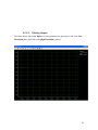
Plotting (TACHLINK Only)
87
4.2.9.1
Plotting Setup
87
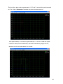
4.2.9.2
Plotting Output
89
4.2.9.2.1
Plotting Toolbar
91
•
Tracking Resume:
91
•
Tracking Pause:
91
•
Axes Scroll:
91
•
Axes Zoom:
91
•
Zoom Out / In:
91
•
Select:
92
•
Zoom Box:
92
•
Data Cursor:
92
•
Edit:
93
•
Copy To Clipboard:
93
•
Save:
93
•
Print/Print Preview:
93
4.2.10
Display (TACHTROL series only)
94
4.2.10.1
Display/Keypad Setup
95
4.2.10.1.1 Display Line 1 & 2
95
4.2.10.1.2 Backlight Timeout
95
4.2.10.1.3 Contrast
96
4.3
Infrared Remote
96
5 Example Applications
97
5.1
97
Basic setup
5.1.1
Material Requirements
97
5.1.2
Connections
97
5.1.3
TACHPAK 10 Programming & Setup (rpm)
98
Input Setup
98
5.1.3.1
Tachometer Mode
98
5.1.3.2
Direction
98
5.1.3.3
Equation & Units
98
5.1.3.4
Logic Low & High
98
5.1.3.5
Averaging
98
5.1.3.6
Normalization
98
5.1.3.7
Units
99
5.1.3.8
Input Type
99
5.1.3.9
Min Freq
99
Relay Output 1 Setup
99
5.1.3.10
Source
99
5.1.3.11
Latch Mode
99
5.1.3.12
On / Off Delay
99
5.1.3.13
Output Switching
99
Digital 1 &2, Relay 2 and Analog Output
99
Security Setup
99
5.1.3.14
Alarm Hold-Off
99
5.1.3.15
Keyboard Lock
99
5.1.3.16
Change Security Code
99
5.1.4
Use Verify to validate setup
100
5.2
Intermediate setup
100
5.2.1
Material Requirements
100
5.2.2
Connections
100
5.2.3
TACHTROL 30 Programming & Setup (Speed)
101
Input Setup
101
5.2.3.1
Tachometer Mode
101
5.2.3.2
Direction
101
5.2.3.3
Equation & Units
101
5.2.3.4
Logic Low & High
101
5.2.3.5
Averaging
101
5.2.3.6
Normalization
101
5.2.3.7
Units
101
5.2.3.8
Input Type
102
5.2.3.9
Min Freq
102
Digital Output 1 Setup (Over speed alarm)
102
Source
102
5.2.3.10
5.2.3.11
Latch Mode
102
5.2.3.12
On / Off Delay
102
5.2.3.13
Output Switching
102
Digital Output 2 Setup
102
Output Switching
102
Relay Output 1 Setup (Failsafe Overspeed alarm)
102
5.2.3.15
Source
102
5.2.3.16
Latch Mode
102
5.2.3.17
On / Off Delay
103
5.2.3.18
Output Switching
103
Relay Output 2 Setup (Failsafe Underspeed alarm)
103
Output Switching
103
Analog Output Setup
103
5.2.3.20
Source
103
5.2.3.21
Range
103
5.2.3.22
Min / Max Value
103
Security Setup
104
5.2.3.23
Alarm Hold-Off
104
5.2.3.24
Keypad Lock
104
5.2.3.25
Display Address
104
5.2.3.26
Change Security Code
104
Display Setup
104
5.2.3.27
Display Line 1 & 2
104
5.2.3.28
Backlight Timeout
104
5.2.3.29
Contrast
104
5.2.4
Use Verify to validate setup
104
5.2.3.14
5.2.3.19
5.3
Advanced Setup
105
5.3.1
Problem Description
105
5.3.2
Material Requirements
106
5.3.3
Connections
106
5.3.4
TACHTROL 10 Programming & Setup (Displacement)
106
Input Setup
107
5.3.4.1
Counter Mode
107
5.3.4.2
Direction
107
5.3.4.3
Equation & Units
107
5.3.4.4
Logic Low & High
107
5.3.4.5
Normalization
107
5.3.4.6
Units
107
5.3.4.7
Counter Type
107
5.3.4.8
Preset
108
Relay Output 1 Setup
108
5.3.4.9
Source
108
5.3.4.10
Latch Mode
108
5.3.4.11
On / Off Delay
108
5.3.4.12
Output Switching
108
Relay Output 2 Setup
108
Output Switching
108
Digital Output 1 & 2 and Analog Output Setup
108
Security Setup
108
5.3.4.14
Alarm Hold-Off
108
5.3.4.15
Keypad Lock
108
5.3.4.16
Display Address
109
5.3.4.17
Change Security Code
109
Display Setup
109
5.3.4.18
Display Line 1 & 2
109
5.3.4.19
Backlight Timeout
109
5.3.4.20
Contrast
109
5.3.5
TACHTROL 30 Programming & Setup (Speed)
109
Input Setup
109
5.3.5.1
Tachometer Mode
109
5.3.5.2
Direction
109
5.3.5.3
Equation & Units
110
5.3.4.13
5.3.5.4
Logic Low & High
110
5.3.5.5
Averaging
110
5.3.5.6
Normalization
110
5.3.5.7
Units
110
5.3.5.8
Input Type
110
5.3.5.9
Min Freq
110
Digital Output 1 Setup
111
5.3.5.10
Source
111
5.3.5.11
Latch Mode
111
5.3.5.12
On / Off Delay
111
5.3.5.13
Output Switching
111
Digital Output 2 Setup
111
Output Switching
111
Relay Output 1 & 2
111
Analog Output Setup
111
5.3.5.15
Source
111
5.3.5.16
Range
112
5.3.5.17
Min / Max Value
112
Security Setup
112
5.3.5.18
Alarm Hold-Off
112
5.3.5.19
Keypad Lock
112
5.3.5.20
Display Address
112
5.3.5.21
Change Security Code
112
Display Setup
112
5.3.5.22
Display Line 1 & 2
112
5.3.5.23
Backlight Timeout
112
5.3.5.24
Contrast
112
5.3.6
Use Verify to validate setup
112
5.3.5.14
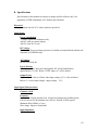
6 Specifications
113
Electrical
Input Power
113
Power consumption, DC Voltage, AC Voltage, Power Sharing, Output Power
Input Signal Characteristics
113
Channel A & B, Frequency, Input Impedance, Input Sensitivity, Common Mode
Rejection Ratio, Electrical Isolation
Verify and Reset
114
Frequency, Input Impedance, Input Sensitivity, Common Mode Rejection Ratio,
Electrical Isolation
Direction
114
Frequency, Input Impedance, Input Sensitivity, Common Mode Rejection Ratio,
Electrical Isolation
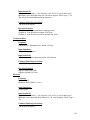
Output Characteristics
Relays (Mechanical)
115
Physical, Contact Rating, Response Time (operates and release), Electrical Isolation,
Switch point Accuracy
Relays (Solid State)
115
Physical, Contact Rating, Response Time (operate and release), Electrical Isolation,
Switchpoint Accuracy
Analog Output
116
Ranges, Accuracy, Resolution, Linearity, Loop Impedance, Response Time,
Electrical Isolation
Display (applies to both remote and integrated displays)
116
Resolution, Accuracy, Communication Protocol, Network, Electrical Isolation
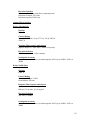
Utility RS485
117
Communication Protocol, Maximum Transmission Distance, Electrical Isolation
USB
117
Processing Platform
117
Clock Speed, Acquisition Time, Accuracy, Resolution
Environmental
118
Operating Temperature, Thermal Cycle, Dielectric Strength, Humidity,
Vibration, Shock, EMC, RoHS
Connectors
118
USB, RS485, Remote Display, Signal And Power I/O
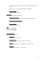
7 Target Variable Conversions
119
8 Annex 1: Startup Databases
120
9 Warranty and Return Shipments Statement
121
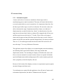
1. Introduction
AI-TEK TACHTROL 10 &30 (TT) and TACHPAK 10 & 30 (TP) series instruments are
dual input, industrial tachometers used to measure the rate of events from a given
process. Using the proportional signal outputs from either passive or active sensors, TT
and TP can measure, monitor and react to events as simple as the speed of a shaft, or as
complex as relating the differential in speed of 2 independent rotating objects.
TACHTROL plus provides additional function as a remote display and also serves as a
gateway for secure, remote programming. Both TT and TP share a common processing
platform. This commonality allows both to perform identical tachometry functions,
streamlines programming and minimizes the learning curve. The main difference
between the two is the characteristic integrated display function found in all TACHTROL
series tachometers.
1.1. Overview
A speed sensor placed near a moving target such as a rotating gear generates a
series of pulses whose frequency is proportional to the speed of the target. This
information is utilized by the tachometer as the basis for its function. Some key
features are as follows. See specification section for specific model and option
applicability.
• Wide range of AC or DC power
• Greatly improved instrument accuracy, processing speed and response time.
• Frequency, period or counter modes.
• User-defined inputs for logic level, averaging, alarm set points and hysteresis,
• Signal normalization and math functions allow mathematical manipulation of
input signals. Results can be displayed along with user-defined units.
• Accepts sinusoidal and square wave inputs as found in variable reluctance and
digital output speed sensors.
• Accepts bi-directional sensor inputs and will decode quadrature or direction
signal logic
• 2 solid state relays (fast response time) and 2 mechanical relays (high power)
• Analog output: 0-20mA, 4-20mA, -20-0-(+) 20mA (can be used with bidirectional sensor)
• Two programming methods: Front panel on display or USB2.0 connectivity to
TACHLINK, a PC / Windows-based GUI (Graphical User Interface). The
GUI can be used to display data, program, perform security functions,
diagnostics, analog output calibration and real-time data logging.
• In the case of tachometer instruments embedded in explosion proof or NEMA
4X enclosures, remote access solves the problem of programming by making
use of an IR link to allow full front panel control via a hand-held remote.
• Utility RS485 communication also allows full GUI function but over longer
distances (up to 8000 ft)
1
•
Drives up to 8 remote displays (TTplus). A single display can be up to 1000 ft
away with a simple RJ11 (phone jack) connection. Longer runs, cable type
and number of displays will affect distance.
• Security mode protects unauthorized access for programming or alarm resets
(through display or GUI)
• Mounts to DIN rail. Power can be applied through special DIN bus when used
with AI-TEK power supply (TP only).
• Environmentally hardened for temperature, vibration and shock. EMC / CE
compliant to current BS EN directives.
• Integrated display capable of two independent output channels for speed,
count period or equation results, Alarm status / security, Mode, User defined
units for each channel, 128x64 LCD graphics display with backlight.
o (TT only)
• Designed and manufactured compliant with RoHS.
1.2. Tools
No special tools are required to perform the procedures in this manual. A flat
blade screwdriver is required for making connections; 1/8”(3.2mm) wide for
TACHPAK and 3/32” (2.4mm) for TACHTROL.
1.3. Notes and cautions
This Manual uses the following conventions to emphasize important information.
Note: Provides an explanation or amplification
Caution: Advises there is risk of damaging equipment if directions are
not followed.
Danger: Advises there is risk to personal health if directions are not
followed.
2
1.4. Where to go for help
For technical support and programming assistance on this product, please contact
your local distributor. To locate a distributor, please use one of the following:
Phone: 1-800-643-0643
website: www.aitekinstruments.com/distributors/
2. Unpacking Instructions
To ensure safe transit, every TACHPAK and TACHTROL is thoroughly tested and
carefully packed prior to leaving the plant. Responsibility for its safe delivery was
assumed by the carrier upon acceptance of the shipment. Claims for loss or damage
sustained in transit must be made with the carrier.
2.1. Package contents
TACHPAK 10 & 30 and TACHTROL 10 & 30 are shipped in a single carton
containing one instrument, TACHLINK and a manual on CD ROM, and a USB
cable.
TACHTROL plus shipped in a single carton containing one instrument and a
display cable with RJ-11 terminations.
TACHLINK PC application for Windows 2000 and XP. Shipped in a single
carton containing a CD and 10ft USB cable.
TACHTROL 10 & 30 and TACHTROL plus Explosion Proof and NEMA 4X are
shipped in a single carton containing one boxed instrument as described above,
one Infrared remote and one DIN rail mounting kit.
3
TACHPAK 10 & 30 Explosion Proof and NEMA 4X are shipped in a single
carton containing one rated enclosure and one boxed instrument as described
above.
2.2. Unpacking
Caution! : TACHPAK and TACHTROL are precision instruments.
Although they are designed to withstand the rigors of industrial use,
excessive physical shock or vibration can cause damage. Handle
carefully. Do not drop or subject to physical extremes.
1.Place the carton on a level surface in a well-lighted area and open the top.
2. Carefully lift out the instrument and separate from any extraneous packing
material.
3. Remove all instrument related materials
4. Inspect for damage
3. Mounting and Wiring Procedures
3.1. Installation and wiring guidelines
•
Locate instrument away from sources of water, heat, humidity, and dust or
provide a suitable enclosure to protect it from these elements.
•
Locate the instrument away from sources of electrical noise such as , but not
limited to: SCRs, triacs, buzzers, horns, motors, welding equipment,
contactors, heavy current relays, and other noise generating electrical
equipment.
•
Use a grounded metal enclosure to protect the instrument from radiated
electrical noise and other magnetic influences.
•
Separate low voltage signal and control wiring from switching and power
wiring. Plan cabinet and panel wiring so that power and relay wiring are
dressed to one side and low-level signals are dressed to the other. Plan wiring
to maintain separation at entry to, and egress from the enclosure.
4
•
Signal and control wiring should be, at a minimum, in twisted pairs. Lines for
magnetic pick-ups and other frequency output devices should be run in
separate shielded cables.
•
Try not to use commutators or slip rings to transmit low-level signals. Should
this be absolutely necessary, ensure that the point of contact is maintained and
clean at all times. Refer questions about this type of application to your local
distributor.
•
Connect the drain from shielded cables so that no current flows in the
shielded cable by first connecting all shield segments in series, then to the
appropriate connection on the tachometer or to an approved earth ground
nearest the instrument.
• Provide a power source that is free of electrical noise and power interruption.
Use either the available AI-TEK DC power supply or one that can operate
within the limits of the instruments specifications. Battery chargers should be
avoided unless isolation can be provided between the tachometer and charger
system.
5
3.2. Mounting guidelines
3.2.1. TACHPAK 10, TACHPAK 30
TACHPAK is designed to mount to 35 mm DIN rail. Locate TACHPAK to
ensure it is adequately protected from the environment and ensure mounting is
secure.
6
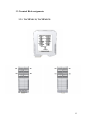
3.2.2. TACHTROL 10, TACHTROL 30, TACHTROL plus
TACHTROL is designed to mount into a panel with a wide range of thickness.
Locate TACHTROL to ensure it is adequately protected from the environment
and ensure mounting is secure.
7
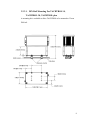
3.2.2.1. DIN Rail Mounting For TACHTROL 10,
TACHTROL 30, TACHTROL plus
A mounting kit is available to allow TACHTROL to be mounted to 35 mm
DIN rail.
8
3.2.3. NEMA 4X Mounting For TACHTROL AND TACHPAK
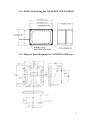
3.2.4. Explosion Proof Mounting For TACHTROL (EXB type)
9
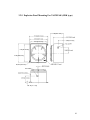
3.2.5. Explosion Proof Mounting For TACHPAK (GRK type)
10
3.2.6. Speed Sensor Mounting Considerations
The sensor should be secured in a rigid mount. Normal machine vibration should
not affect the accuracy of the instrument. However, any relative motion, caused
by a loose sensor or vibrating mount between the sensor and the target can
produce erratic behavior . Consult the applicable AI-TEK Instruments, LLC
product specifications.
3.2.6.1. Speed Sensor Types
AI-TEK offers a wide variety of speed sensors that are compatible with the
tachometer instruments. There are also other sources of speed sensors that are
compatible with AI-TEK tachometers.
3.2.6.1.1.
Active Sensors
Active sensors require power to operate and the output is usually a digital
square-wave. They are necessary for low and zero speed applications.
Sensing technologies are typically Hall effect but also may be Magneto
Resistive.
3.2.6.1.1.1.
Single Channel
Usually 3 wires for connection; power, ground and digital signal
output.
3.2.6.1.1.2.
Dual Channel / Bi-Directional
Usually 5 wires for connection; power, ground, two digital signal
outputs and direction logic. These sensors can determine speed and
direction of a rotating target.
3.2.6.1.2.
Passive Sensors
Passive sensors require no external power to operate. Power is generated
internally during operation. Typically one output only with two signal
wires for connection.
11
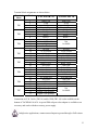
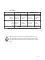
3.3. Terminal Block assignments
3.3.1. TACHPAK 10, TACHPAK 30
12
Terminal block assignments are shown below.
Terminal
Block
TB1
TB2
TB4
TB3
TB5
TB6
TB8
TB7
Pin #
TACHPAK 30
TACHPAK 10
1
2
3
4
5
6
7
8
9
10
11
12
13
14
15
16
17
18
19
20
21
22
23
24
25
26
27
28
29
30
31
32
Input Com
A Sig
B Sig
Direction Input
Verify Verify +
Reset Reset +
Analog Out +
Analog Shield
Analog Out Not Used
In GND
12-30 Volt In
+12 Vdc Out
Out GND
Relay 1 Com
Relay 1 N.C.
Relay 1 N.O.
Not Used
Relay 2 Com
Relay 2 N.C.
Relay 2 N.O.
Not Used
AC/Earth Gnd
Not Used
AC Hot
AC Neutral
Digital 1 (no polarity)
Digital 1 (no polarity)
Digital 2 (no polarity)
Digital 2 (no polarity)
Input Com
A Sig
B Sig
Direction Input
Verify Verify +
Reset Reset +
Not
Available
In GND
12-30 Volt In
+12 Vdc Out
Out GND
Relay 1 Com
Relay 1 N.C.
Relay 1 N.O.
Not Used
Relay 2 Com
Relay 2 N.C.
Relay 2 N.O.
Not Used
AC/Earth Gnd
Not Used
AC Hot
AC Neutral
Not
Available
Connection to12-30 Volt In (TB3-14) and In GND (TB3-14) is also available on the
bottom of TACHPAK 10 & 30. A special DIN rail power bus adaptor is available as an
accessory and works with the accessory power supply.
In high noise applications, connect unused inputs to ground through a 1kΩ resistor.
13
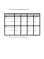
TACHPAK has additional connections that can be made for Remote Displays, USB and
RS485. When mounting, ensure sufficient clearance for cabling.
Terminal
Block
Remote
Display
USB
RS485
DB9
Pin #
TACHPAK 30
TACHPAK 10
Use RJ11 type connector. No individual breakout of pins.
Use USB “B” type connector. No individual breakout of pins.
1,5
GND
2
Tx Not
3
Rx Available
6
Tx +
7
Rx +
4,8,9
Not Used
Remember to select the applicable Comm. connection per section 4.2.1.2
14
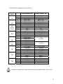
3.3.2. TACHTROL 10, TACHTROL 30
15
Terminal block assignments are shown below.
Terminal
Block
TB1
TB2
TB3
Remote
Display
TB4
TB5
TB6
TB7
TB8
TB9
Pin #
1
2
3
1
2
3
1
2
3
4
1
2
3
4
1
2
3
1
2
3
1
2
3
4
1
2
3
4
1
2
3
4
TACHTROL 30
Relay 1 N.O.
Relay 1 Com
Relay 1 N.C.
Relay 2 N.O.
Relay 2 Com
Relay 2 N.C.
+12vdc Out
Sig Sig +
Gnd
AC/Earth Gnd
AC/Earth Gnd
AC Hot
AC Neutral
Analog Shield
Analog Out +
Analog Out Digital 1
Dig Com
Digital 2
12-30 Volt In
In GND
+12 Vdc Out
Out GND
Verify Verify +
Reset Reset +
Input Com
A Sig
B Sig
Direction Input
TACHTROL 10
Relay 1 N.O.
Relay 1 Com
Relay 1 N.C.
Relay 2 N.O.
Relay 2 Com
Relay 2 N.C.
+12vdc Out
Sig Sig +
Gnd
AC/Earth Gnd
AC/Earth Gnd
AC Hot
AC Neutral
Not
Available
Not
Available
12-30 Volt In
In GND
+12 Vdc Out
Out GND
Verify Verify +
Reset Reset +
Input Com
A Sig
B Sig
Direction Input
In high noise applications, connect unused inputs to ground through a 1kΩ resistor.
16
TACHTROL has additional connections that can be made for Remote Displays, USB and
RS485. When mounting, ensure sufficient clearance for cabling.
Terminal
Block
Remote
Display
USB
RS485
DB9
Pin #
TACHTROL 30 TACHTROL 10
Use RJ11 type connector. See TB3 for individual breakout of
pins.
Use USB “B” type connector. No individual breakout of pins.
1,5
GND
2
Tx Not
3
Rx Available
6
Tx +
7
Rx +
4,8,9
Not Used
Remember to select the applicable Comm. connection per section 4.2.1.2
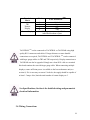
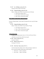
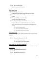
3.3.3. TACHTROL plus
17
Terminal
Block
TB1
Remote
Display
Remote Display
Pin #
TACHTROL plus
1
+12vdc In
2
Sig +
3
Sig 4
Gnd
Use RJ11 type connector. See TB1 for
individual breakout of pins.
TACHTROL plus can be connected to TACHTROL or TACHPAK using high
quality RJ11 connectors and cables. If longer distances or more durable
connections are required, TACHTROL and TACHTROL plus can be connected
with larger gauge cables via TB3 and TB1 respectively. Display connections to
TACHPAK can also be upgraded. Simply run a short RJ11 cable to a terminal
block and continue the run with larger gauge cable. When connecting multiple
displays, ensure sufficient power is available to the base tachometer unit (see
section 6). If it is necessary to run on 12volts dc, the supply should be capable of
at least 1.5 amps. Also, limit the total number of remote displays to 3.
See Specifications, Section 6 for detailed wiring and parametric
electrical information.
3.4. Wiring Connections
18
3.4.1. Speed Sensors
TACHTROL 10 & 30
Sensor Type/Connection
Terminal
TACHPAK 10 & 30
Description
Terminal
Description
Wire 1 TB9, pin 2 or 3
A Sig or B Sig
TB1, pin 2 or 3
A Sig or B Sig
Wire 2 TB9, pin 1
Input Com
TB1, pin 1
Input Com
AC Earth Gnd
TB8, pin 25
AC Earth Gnd
+12 Vdc Out
TB3, pin 15 *
+12 Vdc Out
Out GND
TB3, pin 16 *
Out GND
-common with-
-common with-
Input Com
TB1, pin 1
Input Com
Output TB9, pin 2 or 3
A Sig or B Sig
TB1, pin 2 or 3
A Sig or B Sig
Cable Shield TB4, pin 1 or 2
AC Earth Gnd
TB8, pin 25
AC Earth Gnd
+12 Vdc Out
TB3, pin 15 *
+12 Vdc Out
Out GND
TB3, pin 16 *
Out GND
-common with-
-common with-
Input Com
TB1, pin 1
Input Com
Output 1 (A) TB9, pin 2
A Sig
TB1, pin 2
A Sig
Output 2 (B) TB9, pin 3
B Sig
TB1, pin 3
B Sig
Direction TB9, pin 4
Direction Input
TB1, pin 4
Direction Input
Cable Shield TB4, pin 1 or 2
AC Earth Gnd
TB8, pin 25
AC Earth Gnd
Passive
Cable Shield TB4, pin 1 or 2
Active (single channel)
Power TB7, pin 3 *
{ TB7, pin 4*
Ground{
-common with- -common with{ TB9, pin 1
Active (dual channel)
Power TB7, pin 3 *
{ TB7, pin 4*
Ground{
-common with- -common with{ TB9, pin 1
*Can use external or internal power supply. Ensure all power and signal
common connections are electrically tied together.
19
3.4.2. Power
TACHTROL 10 & 30
Power Type
Terminal
TACHPAK 10 & 30
Description
Terminal
Description
DC
Positive (+) TB7, pin 1
12-30 Volt In
TB3, pin 14
12-30 Volt In
Negative (-) TB7, pin 2**
In GND
TB3, pin 13**
In GND
AC Hot
TB8, pin 27
AC Hot
AC Neutral
TB8, pin 28
AC Neutral
AC Earth Gnd
TB8, pin 25
AC Earth Gnd
AC
Hot TB4, pin 3
Neutral TB4, pin 4
Earth TB4, pin 1 or 2
Both can be connected simultaneously
DC & AC
** Ensure all power and signal common connections are electrically tied together.
When using external power supplies to power either the tachometer or sensor,
ensure that all ground connections are common. Be careful not to create ground
loops. Bad grounds and ground loops can cause erratic behavior in any electronic
device.
20
3.4.3. External Verify and Relay Reset Circuit
TACHTROL 10 & 30
External Function
Terminal
TACHPAK 10 & 30
Description
Terminal
Description
Verify *
3.5 – 30 Vdc > switch > TB8, pin 2
Verify +
TB2, pin 6
Verify +
Verify -
TB2, pin 5
Verify –
Reset +
TB2, pin 8
Reset +
Reset –
TB2, pin 7
Reset –
|
>>>>>>>>> Ground > TB8, pin 1
Reset *
3.5 – 30 Vdc > switch > TB8, pin 4
|
>>>>>>>>> Ground > TB8, pin 3
*Can use external or internal power supply. Ensure all power and signal
common connections are electrically tied together.
21
3.5. USB (all TACHTROL and TACHPAK instruments)
USB is the simplest way to connect a computer to TACHTROL or TACHPAK. When
TACHLINK is loaded onto a pc it allows full access to programming and viewing
tachometer functions and outputs. There are 2 popular methods of connection.
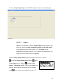
3.5.1. Direct USB link
Use a high quality USB 2.0 A/B cable. Maximum transmission distance is
approximately 10 to 15 ft. USB booster / distance
extenders are available that allow distances up to
approximately 150 ft. Connect the “A” (larger) end to your
computer and the “B” (smaller) end to the tachometer. See
section 3.0 for installation instructions prior to connecting.
When connecting, one at a time, to multiple tachometers, the system may request
the TACHLINK installation disk be re-inserted to re-install certain files.
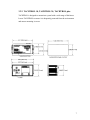
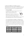
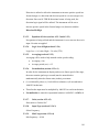
3.5.2. USB to RS-485 link (TACHTROL / TACHPAK 30 only)
Some computers do not have a serial port available to connect the RS-485. A
second method to utilize the USB connection on the computer is to use a RS-485
to USB converter such as the B&B electronics model USOTL4 or equivalent.
This device is port powered and provides electrical isolation between tachometer
and computer. Make connections as defined below or follow manufacturers
instructions.
USOTL4
Designation
GND
RDATDA RDB+
TDB+
N/A
TACHTROL/TACHPAK 30
Designation
Pin
GND
1 or 5
Tx 2
Rx 3
Tx +
6
Rx +
7
Not Used
4,8,9
22
Set Dip Switches and install any necessary drivers for converter device as directed
by manufacturers instructions. Windows will configure the converter as an
additional COM port.
3.6. RS-485 link (TACHTROL / TACHPAK 30 only)
RS-485 allows full TACHLINK function and the ability to communicate over
thousands of feet. Typically, the need to reload files from the installation disk is
eliminated when connecting, one at a time, to multiple tachometers.
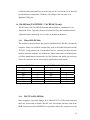
3.6.1.
Direct RS-485 link
This method is the most direct but requires installation of a RS-485 card into the
computer. Many are available commercially such as the B&B electronics model
3PCIOU1 or equivalent. It is recommended to use a card that provides electrical
isolation between computer and tachometer. Make connections as defined below
or follow manufacturers instructions. Set Dip Switches and install any necessary
drivers for converter device as directed by manufacturers instructions.
3PCIOU1
Designation
GND
RDTD RD+
TD+
N/A
3.6.2.
Pin
5
1
3
9
2
N/A
TACHTROL/TACHPAK 30
Designation
Pin
GND
1 or 5
Tx 2
Rx 3
Tx +
6
Rx +
7
Not Used
4,8,9
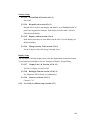
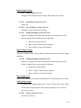
RS-232 to RS-485 link
Many computers, especially laptops, have either RS-232 or USB connections and
there may be no room to install a RS-485 card. An external converter such as the
B&B electronics model 4WSD9TB or equivalent allows the connection of the
23
tachometer in such situations. Make connections as defined below or follow
manufacturers instructions. Set Dip Switches and install any necessary drivers for
converter device as directed by manufacturers instructions.
4WSD9TB
Designation
GND
RDATDA RDB+
TDB+
N/A
RS-232
TACHTROL/TACHPAK 30
Designation
Pin
GND
1 or 5
Tx 2
Rx 3
Tx +
6
Rx +
7
Not Used
4,8,9
RS232 – RS485 converter
⇐ Tach
RS-485
DB9 Cable (straight thru)
Remember to select the applicable Comm. connection per section 4.2.1.2
24
Using the Windows Application
3.7.
3.7.1. Loading TACHLINK Onto Windows 2000 or XP.
•
Load onto your pc prior to connecting with either USB or RS485. Close all unnecessary applications.
•
Once inserted, the CD should automatically load the installation. If not, click START then RUN. Type
“X:\Setup.exe” (replace “X” with the correct drive letter for the applicable CD-ROM drive, typically D). Follow
the on-screen instructions to complete the installation.
•
If your pc does not have Microsoft ® .NET 1.1 Framework, it will install first. Follow the on-screen instructions
to complete the installation. When complete, restart the computer and log in if necessary. TACHLINK will now
install. Follow the on-screen instructions.
•
When complete AI-TEK TACHLINK and manual icon will appear on your desktop. All starter databases are
loaded.
•
Connect power to tachometer, then connect USB.
•
Found New Hardware Wizard will start:
o
Select NO if asked to allow connection to Windows Update. > Click NEXT
o
Insert Installation /Disk > Select Install Automatically > Click NEXT
o
If Logo Compatibility notice appears, select Continue Anyway.
o
System should find USB driver file. If not, the following dialog box will appear:
[Insert the CD labeled “FTDI FTD2XX Drivers Disk” into your CD ROM]
o
Insert CD > Click OK
o
System should find USB driver file. If not, the following dialog box will appear:
[The file’FTD2XX.sys’ on FTDI FTD2XX Drivers Disk is needed]
o
Click BROWSE > X:\program files\Aitek\Tachlink\USB Device Driver\FTD2XX
o
Highlight file “FTD2XX” > click OPEN.
o
The following dialog box will once again appear:
[The file’FTD2XX.sys’ on FTDI FTD2XX Drivers Disk is needed]
o
Click OK.
o
Click FINISH to complete Found New Hardware Wizard.
o
Launch TACHLINK and select Program > COMM Port and either USB or applicable COMM port
to establish communication per section 4.2.1.2 of manual. Make wiring connections per section
3.5 (USB) or section 3.6 (RS485). A dialog box may appear when TACHLINK is first launched:
Couldn’t open .cfg file. Click OK, the file is generated when first opened.
25
4. Tachometer Functions
Both TACHPAK and TACHTROL are highly configurable instruments. This allows
the instrument to perform very simple to very complex tasks. Both are designed to
communicate with remote TACHTROL plus displays via a dedicated LAN (Local
Area Network). Each tachometer series can be connected to up to eight remote
TACHTROL plus displays (when using the TACHTROL series, the instrument counts
as one display), a PC loaded with TACHLINK through USB2.0 and a PC loaded with
TACHLINK through RS485 simultaneously. Only one tachometer can be connected
to any given network and it serves as bus master for that network. The tachometer
instrument also serves to store the active configuration constants that define its
behavior. Both TACHPAK and TACHTROL cannot be connected on the same
network. In terms of programming, any TACHTROL display panel or remote PC can
be used to program the tachometer. Whenever a user begins to change configuration
data in the tachometer, unlock is granted for only that port and all other ports are
locked out until the programming cycle is completed. During programming, all other
ports on the LAN will continue to monitor and display active process information. All
configuration constant data is stored in the tachometer instrument and is global to the
entire network. Each display, however, can be configured to display different
information. For example, Remote Display 1 can be configured to display channel A
and channel B information while Remote Display 2 may display channel B and the
result of a calculation (Equation)
4.1. Programming The Tachometer
Programming either through the front panel or via TACHLINK has been designed
to be as similar and intuitive as possible. Programming through the front panel
utilizes a series of nested menus. The user navigates through the menus and
changes data via a set of Up, Down, Left, Right arrows. TACHLINK is included
with all TACHPAK AND TACHTROL products and simplifies the mechanics of
programming. Anyone familiar with Windows can easily navigate through a
series of tabbed screens. Each screen is designed to contain logically associated
26
functions and tracks the nested menus used in front panel programming.
TACHLINK also allows additional function including Analog output calibration
(see section 4.2.5.2) as well as the ability to track and plot rate information over a
long period of time. (see section 4.2.9) Programming can be accomplished at
either the installation site or off site, then debugged, with features integrated in
the tachometer, all prior to committing to the first “live” run.
When programming a TACHPAK, it is necessary to have either a TACHTROL
plus
or TACHLINK to act as the communication gateway. Because of the high
level of similarity, both front panel and TACHLINK programming will be
discussed together.
There are functional differences between TT/TP10 and TT/TP30. The “10” series
does not include Analog Output, Digital 1 & 2 outputs and the utility RS485
serial port. As such the “10” series omits those functions from the GUI and
display menus. This discussion of programming focuses on the “30” series.
Simply disregard discussion of those options that do not apply.
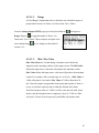
4.1.1. Basic Programming Rules
4.1.1.1. Exponential Notation
This tachometer device is designed to automatically switch from standard
notation to exponential notation if the number to be displayed grows too large
or too small for the number of digits supported by the display. Many userdefined constants must be input as exponential notation, especially when
programming through the display front panel . Exponential notation allows the
instrument to support high-resolution measurements and calculations without
the need for an extreme number of digits on the display. For those unfamiliar
with Exponential notation, the format is a base number followed by an “e”
(exponent) to a given power of 10. If the sign preceding the exponent is
positive, move the decimal point to the right the same number of places as the
value of the exponent, if negative, move the decimal point to the left. When
27
the sign of the exponent is negative, the larger the exponent value, the smaller
the number. When the sign is positive, the larger the exponent value, the
larger the number.
For example:
1) 1.5674e-3 = 1. 5674 x 10-3 = 1.5674 x .001 = .0015674
2) 1.5674e+3 = 1.5674 x 103 = 1.5674 x 1000 = 1567.4
-and3) -1.5674e-3 = -1. 5674 x 10-3 = -1.5674 x .001 =-.0015674
4) -1.5674e+3 = -1.5674 x 103 = -1.5674 x 1000 = -1567.4
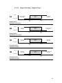
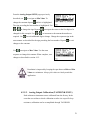
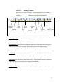
4.1.1.2.
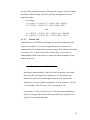
Number Line
TACHPAK and TACHTROL are designed to respond to both positive and
negative real numbers. A reversal in target direction (ex. clockwise to
counterclockwise) is interpreted as a negative speed. This concept is discussed
in section 4.2.2.1. In order to utilize the concept fully, it is necessary to
understand the number line and how it relates the relative magnitude of one
number to the next.
-100
-50
0
+50
+100
In the figure shown, numbers to the left of zero are negative; the further
left you go, the more negative the number gets. To the right of zero,
numbers are positive; the further right you go, the more positive the
number gets. In terms of relative magnitude, -50 is greater than –100, but
+50 is less than +100. Of course, +100 is greater than –100.
For example, if a relay set point is set at –100 (alarm trip) and the alarm
mode is to energize when the speed increases above the setpoint (EA), a
speed of –99 would trip the alarm.
28
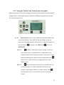
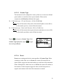
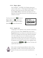
4.1.2. Using the Tachtrol and Tachtrol plus front panel
Both front panels have the same configuration and operate identically. Each front panel is
equipped with a LCD graphics display, Up/Down/Left/Right navigation keys, an enter
key and two function keys.
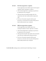
4.1.2.1.
Function Keys allow access to different configuration modes and
operational functions. The actual key function changes as the user
makes selections and is indicated above the key on the LCD display. In
the figure above,
is used to access MENU and
is to access
SECURITY
4.1.2.1.1.
(MENU) allows entry into the “Change” menu area
where sub-menus are listed that allows configuration of userdefined constants in the Tachometer mode, Counter mode, Verify
function and Diagnostics function. Once in those sub-menus,
(Main or Prev) allows the user to navigate back to the main
display screen.
4.1.2.1.2.
allows entry into the security area. From Here the user
can Reset an alarm, set Alarm Hold-Off, Lock/Un-lock the
keypad, set the Display Address or Change Security Code.
also allows the user to access the Next screen in a series of
screens.
29
4.1.2.2. Up/Down/Left/Right Arrow Keys
arrows are used to navigate to menu selections above and
below your current position.
arrows are also used to increment
and decrement a user-defined constant.
arrows are used to
navigate over to a user-defined constant within the same line.
,
,
,
keys also have the numbers 1 through 4 associated with them.
They are used to configure and enter the security code.
4.1.2.3.
The
Enter
key has several basic functions.
is used to select a highlighted
menu item, toggle through a series of Fixed Range Constants, make a
Variable Range Constant active for change, exit a Variable Range
Constant character field or accept an input or choice.
4.1.2.4.
Constant Types
There are two types of user-defined constants:
Fixed Range Constants: These constants limit the level of user-defined
configuration from a pre-determined list and can be numerical or
alphanumerical. Navigate to the line you wish to change with the
Up/Down arrow keys. When the line is highlighted, depress the Enter key.
The value will change for each time the key is depressed. When the
change is complete, simply navigate off the current line with the up/down
keys and to the next line to change.
Variable Range Constants: Constant values are numerical and can be
changed within the resolution of the variable. Navigate to the line you
wish to change with the up/down arrow keys. When the line is highlighted,
depress the enter key. The cursor will be placed at the most significant
digit of the variable. Use the up/down keys to change the value of that
digit. Use the left/right keys to move to the next digit within the field to be
30
changed. When changes are complete, depress the enter key to return back
to navigation.
key, until
After changes are made to any field, depress PREV,
you reach the first drop down menu then MAIN
key. The
tachometer will ask the question:
“Changes have been made to system parameters. Save the
changes? Yes/No.”
Select yes to save the changes. The tachometer will display “Busy”
during the downloading process. When MAIN re-appears, the
instrument is ready to measure or accept additional changes. If at any
time another display has been granted unlock and is in the process of
changing data, all other displays are locked from making changes.
Regardless of where changes are made from; a remote display,
TACHTROL, or the TACHLINK GUI, all global, system constants and
changes are saved in the main tachometer instrument. Changes have not
been made unless you are asked if you wish to save them.
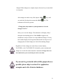
If you need to get started with as little preparation as
possible, please skip to section 5 for application
examples and a list of starter databases.
31
4.2. Navigating Menus And Changing Constants
This section has two main purposes. The first is to define and illustrate
tachometer functions. The second deals with the mechanics of navigating
through menus and changing user-configurable constants. Section 5, Example
Applications, will provide actual examples for the user to follow. Due to
similarities in the mechanics of navigation through menus and changing
constants, examples of each will not be shown, however they are all defined in
detail. Instruction on navigating to, and changing constants is covered early in
this section. Description of changing constants through the TACHTROL
display or TACHLINK may vary with each subsequent example.
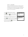
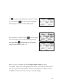
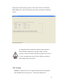
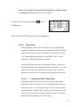
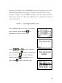
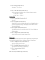
4.2.1. Main
The TACHTROL plus main display screen serves as the visual information
center. Along the top edge, the available Digital and Relay outputs are displayed
as well as alarm status for each. Alarm status is shown as a highlighted box
around the appropriate alarm designator. In the upper right corner, a T or C is
displayed to indicate if the instrument is in the Tachometer or Counter mode.
The tachometer can input two channels of frequency (A&B). In the center
section of the screen the user can configure the instrument to display either one
or both channels or a frequency channel and the mathematical result of an
equation (E:). Just below the lower line, the user can define a set of units for the
active channels being displayed above.
The display view shown indicates an alarm only on Digital Relay 1, Tachometer
mode is active, Channel A and B are
both active, user-defined Units for A
is “rpm” and B is “frequency”. Menu
, Security is
is assigned to
assigned to
.
32
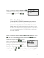
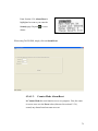
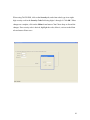
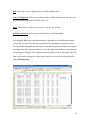
In contrast, TACHLINK is shown below. It displays Input A, B and Equation
simultaneously. Input A is indicating 1.451 with units of “rpm”. Input B is
indicating 507.743 with units of “Frequency”. The Equation line is indicating
1.4506209 (essentially “A”) and has no units. The display also indicates an
alarm is in effect on DIG1 (in red). The green “Online” status light and Status
bar at the bottom of the display indicate the tachometer is connected to the
network and accessible through TACHLINK. Along the top edge of the GUI are
a series of tabs that enable access to all of the user-configurable functions. They
will be discussed in greater detail in subsequent sections of this manual.
In the upper left corner is a pull down menu called Program containing Database Open,
Database Save, Comm. Port, About and Exit.
33
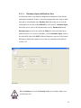
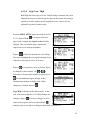
4.2.1.1.
Database Open and Database Save
As discussed earlier, user-defined configuration constants are stored in the
tachometer instrument. If there is a need to propagate the same setup to other
networks or to backup the data, Database Save allows the user to save the
configuration as it exists on TACHLINK to a file on a PC. Database Open
allows the user to retrieve the file and make it active. Database Save and
Database Open are not active under the Main tab. Select any other tab to
make them active. To retrieve a Database, click on Database Open, click on
the desired file, then click OPEN. When a Database is retrieved, click on the
Main tab to initiate the sequence to save the new constants as described in
section 4.1.2.
When a Database is saved, the Security code is saved with it. Make sure
you take note of it.
34
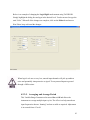
4.2.1.2. Communication Port
TACHLINK can be connected to a tachometer network in a number of ways.
Clicking on Comm. Port brings up the dialog box shown below. Available
Com Ports will vary by computer, however the most common are USB,
Com1, Com2, Com3, etc. The simplest and most convenient way to connect is
through USB when the PC or laptop can be located near the Tachometer. If
the user chooses, one of the Com ports can be assigned for serial
communication for either RS485 (native to the tachometer) or RS232. This
subject is discussed in more detail in sections 3.5 and 3.6. The active port is
listed in the blue bar on the dialog box.
35
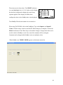
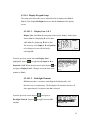
4.2.1.3. About
Provides information pertaining to TACHLINK, AI-TEK, and software
revision.
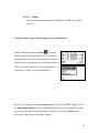
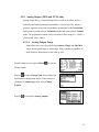
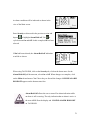
Accessing change menus from the display is as described below.
From the Main screen, depress Menu,
, to list the
Change menus. Each menu allows access to different
operating modes as well as user-configurable constants.
Modes allow the instrument to have personalities that are
tailored to specific function. The four main modes are
Tachometer, Counter, Verify and Diagnostics.
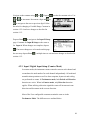
Below is an example of selecting Tachometer mode using TACHLINK. Simply click on
the Digital Input Setup tab, then on the desired menu down arrow and then click on the
desired selection. When all of the changes are complete, click on the Main tab and
answer Yes / No to keep or discard the changes.
36
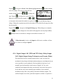
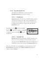
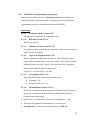
4.2.2. Input / Digital Input Setup (Tachometer Mode)
Input Setup allows the user to configure a set of global constants that affect how
the tachometer reacts to incoming signals. In tachometer mode, the instrument
measures and reacts to external events in terms of frequency or rate. All math and
normalization operations as well as alarm setpoints, hysteresis and scaling are
performed as frequency, speed or rate. When in Tachometer mode, both Period
and Direction detection are active. In counter mode, only direction detection
applies. Direction will be discussed in more detail in subsequent sections.
In order to access special menus for Counter, Tachometer, Direction,
etc, the mode must first be selected and active. Select the mode (as
illustrated below), exit to the Main screen and save the change. Re-entry
into the menus will now provide the mode-specific constants. See
in section 4.2.3 for greater detail.
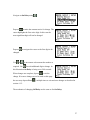
37
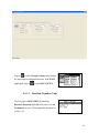
Depress
to select Change Tach and to display the
Input/Output configuration menus. With INPUT
highlighted, depress
to enter INPUT SETUP.
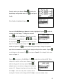
4.2.2.1. Direction Detection
Direction detection allows the tachometer to monitor and react not only to
speed information, but to direction as well. In tachometer mode, a negative in
front of the speed indicates a reversal in direction. Alarm setpoints and
hysteresis can be set to react to target reversal. In counter mode, the count will
increment in one direction and decrement in the reverse direction. Analog
output can be configured to provide –20 to +20mA. –20 mA indicates a
reverse direction, 0 mA indicates stop and +20mA indicates a forward
direction. This will be discussed in greater detail in a subsequent section.
Direction detection is accomplished in two ways.
4.2.2.1.1.
Quadrature
When set for direction mode, the instrument can decode direction based on
two digital signals whose rising edges are spaced 45° to 135° apart such
that one channel leads (or lags) the other. The signals can come from two,
independent sensors, or from a bi-directional sensor such as an AI-TEK
BH series sensor. The instrument can be user-configured to react to either
A leads B (ALB) or B leads A (BLA) as a reversal in direction.
See section 3.4 for connection information.
38
4.2.2.1.2.
Direction Bit
When set for direction mode, the instrument can recognize an externally
applied logic level present at the Direction input. An AI-TEK BH series
bi-directional sensor can provide the logic level signal. The instrument can
be user-configured to react to either high (Bit High) or low logic (Bit
Low) level as a reversal in direction.
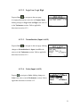
Once in INPUT SETUP, Direction is highlighted.
Depress
once for each choice of the Fixed Range
Variable. Pictured here,
is depressed until Dir. Bit
High is displayed. Once the selection is made, the user
can navigate to the next constant to change or view.
Depressing
will highlight, and make active, Equation
and Units. If no more changes are to be made on this
page the user may depress Prev,
, to exit and save
changes as described in section 4.1.2.
39
Below is an example of changing the Direction constant using TACHLINK. Simply click
on the menu down arrow and click on the desired selection. When all of the changes are
complete, click on the Main tab and answer Yes / No to keep or discard the changes.
4.2.2.2. Equation
This global, Fixed Range Variable assigns a mathematical equation to both of
the input frequencies. The equation allows calculation of the reciprocal for
each channel as well as methods to mathematically relate the two channels.
Available equations are A, 1/A, B, 1/B, A-B, B-A, (A+B)/2, A+B, AxB, A/B,
B/A, (A-B)/A x 100, (B-A)/A x 100. Follow the previous examples for
changing the Direction constant. Equation is one of the possible inputs that
can be assigned to any of the outputs.
40
From the previous section, navigate to Equation using
until Equation is highlighted. Toggle through the available
equations using
. Navigate off using
or
.
4.2.2.3. Units (For Equation)
The units apply only to the equation. Additional units can be specified for
Input A and B, described later in a subsequent section. Up to 10 characters
(numbers, letters and symbols) can be used to describe the units associated
with this constant. The unit label is then displayed to allow the user to know,
at a glance, what is being measured or calculated. Characters are selected from
a pick list when programming from a TACHTROL display or simply typed in
when using TACHLINK.
From the previous section, navigate to Units using
until Units is highlighted. Depress
to make active. Toggle through the available characters using
first character is selected, depress
to move to the
adjacent character. Repeat use of
or
or
. When the
to make the
next selection. Repeat this sequence up to 10 times. If at
anytime the user wishes to remove the Units label,
depress Clear. When complete depress
change. Navigate off using
user may depress Prev,
or
to exit from
. If no more changes are to be made on this page the
, to exit and save changes as described in section 4.1.2.
41
4.2.2.4. Logic Low / High
Both High and Low logic levels are Variable Range Constants and can be
adjusted by the user to tailor the input to provide the largest noise margin
possible or to filter against specific amplitude levels. Logic levels are
adjustable as positive numbers only.
From the INPUT SETUP pages described in section
4.2.2.3, depress Next,
, to navigate to the next
page. In this example, the Logic Low level will be
changed. This is a variable range constant and
requires the user to change the number.
Depress
to make the constant active for change.
The cursor highlights the most significant digit and is
required to enter logic levels of 10 or more.
Depress
to navigate the cursor to the first digit to
be changed for this example. Use
or
to
increment or decrement the number as required. Use
for each additional digit to change. In this
illustration no changes are being made. When
changes are complete, depress
.
Logic High is changed in the same manner. In this
case, it has been changed to 2.20. When changes are
complete, depress
. If no more changes are to be
made on this page the user may depress Prev,
,
multiple times to exit and save changes as described in section 4.1.2.
42
Below is an example of changing the Logic High Level constant using TACHLINK.
Simply highlight the dialog box and type in the desired level. You do not need to type the
unit “Volts”. When all of the changes are complete, click on the Main tab and answer
Yes / No to keep or discard the changes.
When logic levels are set very low, unused input channels will pick up ambient
noise and potentially interpret noise as signal. Tie any unused inputs to ground
through a 1KΩ resistor.
4.2.2.5. Averaging and Average Period
This Variable Range Constant can be turned On or Off and allows the
instrument to average multiple input cycles. The effect is to help smooth out
input frequencies that are “hunting” and not as stable as required. Adjustment
is in seconds from .05 to 60.
43
From section 4.2.2.4 navigate to Averaging using
.
With Averaging highlighted, toggle between On or Off
using
.
Navigate to Average Period using
. Depress
to
make the constant active for change. The cursor
highlights the most significant digit and is required to
enter values of 10 or more.
Depress
or
to navigate the cursor to the first digit to be changed for this example. Use
to increment or decrement the number as required. Use
for each additional
digit to change. In this illustration, the number was set to 4.00. When changes are
complete, depress
depress Prev,
. If no more changes are to be made on this page the user may
, multiple times to exit and save changes as described in section 4.1.2.
Averaging should only be applied where a “smoothed” speed can be
tolerated and where the exact speed does not need to be known. When
Averaging is applied, all outputs including Digital, Relays, Analog and
Display are affected. Averaging will increase the amount of time the
instrument uses to respond to an alarm condition and the response is
based on the mathematical average.
44
4.2.2.6.
Input Setup / Input A & B
Input Setup for input channels A & B are specific to each input, however the
actual constants available and the mechanics for configuration are the same.
4.2.2.6.1.
Normalization
Normalization is a mathematical Variable Range Constant used to convert
the input frequency into a number that is useful to the user. For instance,
the output of a sensor connected to a wheel driving a conveyor belt is in
frequency, however, feet per minute may be more appropriate. For
example:
Assuming a 0.5 ft diameter wheel and a frequency of 10 cycles/sec;
Feet/minute=(cycles/sec) x (60 sec/minute) x (πD/cycle)
=(10 cycles/sec) x (60sec/minute) x (π x 0.5/cycle)
=(10 cycles/sec) x (94.3)
= 942.5 feet per minute
Therefore the calculated rate is 942.5 ft/min and the normalization factor
(in this instance) to convert cycles /sec to feet/minute = 94.3
Normalization is entered as a positive or negative number. When using a
TACHTROL display enter the number as an exponent (see section 4.1.1.1).
Simply type the desired number and polarity when using TACHLINK.
Normalization is mathematically applied to the input frequency first,
then Equation is applied to the result.
45
From the INPUT SETUP pages last described in section 4.2.2.5
Depress Next,
, to navigate to the Input A Setup
page. Normalization will be highlighted. Depress
to make the constant active for change. The sign
preceding the base number is highlighted. Use
to change the sign. Depress
or
to navigate the
cursor to the first digit to be changed for this example. Use
decrement the number as required. Use
or
to increment or
for each additional digit to change. Change
the exponent sign in the same manner as described for the sign preceding the base
number.
4.2.2.6.2.
Units A & B
Up to 10 characters (numbers, letters and symbols) can be used to describe
the units associated with this constant. The unit label is then displayed to
allow the user to know, at a glance, what is being measured or calculated.
Characters are selected from a pick list when programming from a
TACHTROL display or simply typed in when using TACHLINK
From the previous section, navigate to Units using
until Units is highlighted. Depress
to make active.
Make changes as described in section 4.2.2.3.
If Direction mode is active, only Input A will be active and there will not
be a choice to configure Input B.
46
4.2.2.6.3.
Input Type (A & B)
Input Type is a Fixed Range Constant and changes the instrument from
Frequency to Period measurements. Period is a sub-mode to Tachometer
mode and allows the instrument to measure and react to external events in
terms of time. If the user is attempting to measure events that are spaced
far apart, the frequency will be very low, however the period, or time
between events will be relatively large. All math and normalization
operations as well as alarm setpoints, hysteresis and scaling are performed
as period. Period is the reciprocal of frequency.
Navigate to the constant using
. Depress
to
toggle between Frequency and Period.
When selecting Input Type using TACHLINK. Simply click on the menu down arrow
and click on the desired selection. When all of the changes are complete, click on the
Main tab and answer Yes / No to keep or discard the changes
4.2.2.6.4.
Minimum Frequency / Maximum Period
As described earlier in this section, frequency and period have different
uses. By defining what the Minimum Frequency or the Maximum
Period is, the user instructs the tachometer how long to wait until zero
speed is indicated. By carefully selecting these values, reaction time to
long events that approach or reach zero can be significantly reduced.
When Frequency is chosen from section 4.2.2.6.3, Min Freq (Hz) is
active. When Period is chosen from section 4.2.2.6.3, Max Period (sec) is
active. When the actual input rate falls past the specified Min Freq / Max
Period, “LOW” is displayed.
47
Navigate to the constant using
or
or
. Depress
to increment/ decrement a digit and
to make the constant active. Use
or
to navigate to the next or previous digit. Follow
the rules for changing a Variable Range Constant in
section 4.2.2.4 and save changes as described in
section 4.1.2.
Depress Next,
, to navigate to the Input B Setup
page. Constants for Input B Setup are the same as
for Input A. When changes are complete, depress
. If no more changes are to be made on this page
the user may depress Prev,
, multiple times to exit and save changes as described in
section 4.1.2.
4.2.3. Input / Digital Input Setup (Counter Mode)
In counter mode, the instrument counts external events on each channel and
accumulates the total number for each channel independently. All math and
normalization operations as well as alarm setpoints, hysteresis and scaling
are performed as counts. In Tachometer mode, both Period and Direction
detection are active. When in Counter mode, only Direction detection
applies. When utilizing a direction signal the count will increment in one
direction and decrement in the reverse direction.
Most of the User-configurable constants remain the same as in the
Tachometer Mode. The differences are outlined below.
48
In order to access special menus for Counter, Tachometer, Direction, etc,
the mode must first be selected and active. Select the mode (as illustrated
below), continue to navigate to the first user-configurable constant and make
an arbitrary change. This is necessary to force the tachometer to recognize
that a change had been made. Exit to the Main screen and save the change.
Re-entry into the menus will now provide the mode-specific constants.
From the Main screen, depress Menu,
, to list the
Change menus.
Depress
to navigate to Change Counter.
Below is an example of selecting Counter mode using TACHLINK. Simply click on the
menu down arrow and click on the desired selection. When all of the changes are
complete, click on the Main tab and answer Yes / No to keep or discard the changes.
49
Depress
to select Change Counter and to display
the Input/Output configuration menus. With INPUT
highlighted, depress
to enter INPUT SETUP.
4.2.3.1. Direction, Equation, Units
The first page in INPUT SETUP containing
Direction, Equation and Units is the same as in the
Tachometer section. Follow applicable directions in
section 4.2.2.
50
4.2.3.2. Logic Low, Logic High
Depress Next,
, to navigate to the next page.
Averaging functions are not active in Counter Mode.
Making changes to Logic Low and High is the same as
in the Tachometer section. Follow applicable
directions in section 4.2.2.
4.2.3.3. Normalization (Input A & B)
Depress Next,
, to navigate to the next page. Making
changes to Normalization for Input A and B is the
same as in the Tachometer section. Follow applicable
directions in section 4.2.2.
4.2.3.4. Units (Input A & B)
Depress
to navigate to Units. Making changes to
Units is the same as in the Tachometer section. Follow
applicable directions in section 4.2.2.
51
4.2.3.5. Counter Type
The instrument can be configured to count up from zero or some user-defined
preset number or count down from a preset number. When used in
conjunction with Direction, additional rules apply:
Ex. 1: If Counter type = UP and Direction = ALB or Dir Bit High
THEN Count will increment in the positive direction until phase reverses (BLA)
or direction bit goes low; count will then decrement
Ex. 2: If Counter type = Down and Direction = BLA or Dir Bit Low
THEN Count will decrement in the negative direction until phase reverses (ALB)
or direction bit goes high; count will then increment
Depress
to navigate to Counter Type. With
Counter Type highlighted, depress
to toggle
between Up and Down.
4.2.3.6. Preset
Preset sets a starting point for the count regardless of Counter Type. When
counting up, either from zero or a Preset, the counts will increment to an
alarm setpoint, trigger the alarm and continue up to the limit of the instrument.
When counting down, either from zero or a Preset, the counts will continue to
decrement to an alarm setpoint, trigger the alarm, switch from positive to
negative and continue to the limit of the instrument is reached.
52
Depress
to navigate to Preset. With Preset highlighted depress
to make constant
active for change. The sign preceding the base
number is highlighted. Use
sign. Depress
or
to change the
to navigate the cursor to the first
digit to be changed for this example. Use
or
to increment or decrement the number as required. Use
for each additional digit to
change. Change the exponent sign in the same manner as described for the sign preceding
the base number.
Depress Next,
depress
, to navigate to the Input B Setup page. When changes are complete,
. If no more changes are to be made on this page the user may depress Prev,
, multiple times to exit and save changes as described in section 4.1.2.
If Direction mode is active, only Input A will be active and there will not
be a choice to configure Input B.
4.2.4. Digital Output 1&2 (TP30 and TT30 Only), Relay Output
1&2 / Digital Output Setup (Tachometer and Counter Mode)
The tachometer has four switched outputs; Relay 1 and 2 are based on
mechanical relays that provide high isolation and power switching but do not
react as quickly as semi-conductors. Each mechanical relay has a set of
normally open and normally closed contacts. Digital 1 & 2 are semiconductor based outputs that reduce reaction time, but switch lower power
levels and have only a true normally open condition. Just as with the
mechanical relays, there is no polarity associated with these outputs. The
switched outputs react when a particular setpoint is reached. A setpoint is a
53
value of normalized units that represents a significant point within the speed,
frequency, period or count range of the input signal that causes a relay to
change state. “Energized” describes the condition where the relay is “On”
and the normally open contacts are closed. “De-energized describes the
condition where the relay is “Off” and the normally open contacts are open.
The frequency, after normalization may be expressed as cycles per second,
gallons per hour, etc. Therefore, setpoint and hysteresis is expressed in the
same user-defined, normalized units. There are several types of relay
behavior divided into two major classifications; Failsafe and Non-failsafe.
This is discussed in great detail in subsequent sections.
Output setup is the same for all Digital and Relay outputs in both
Tachometer and Counter Mode. Therefore the following discussion
applies in all cases. The terms speed, frequency, period or count are
interchangeable for this discussion.
From the Main screen, depress Menu,
, to list the
Change menus.
Depress
to select Change Tach and to display the
Input/Output configuration menus. If the intent is to
configure a Counter application, select Change
Counter.
Depress
to navigate to Digital Output 1. Depress
additional times to configure other outputs.
To enter Digital Output Setup in TACHLINK simply click on the corresponding tab.
54
Digital Output Setup allows the user to configure the outputs individually. Each output
can be assigned to a specific normalized frequency input and to switch on (alarm) and
reset in a particular manner. The following is a very detailed description of setpoints and
switching behavior utilized by Digital Output 1&2 and Relay Output 1&2.
4.2.4.1. Source
Source is a Fixed Range Constant. Each output can be assigned to any input.
The user can decide to assign one or all of the outputs to a single input. The
choices are Input A, Input B, Equation or Off. Input A & B are the
normalized values from section 4.2.2.6. Equation uses the mathematical
result from section 4.2.2.2 in addition to Normalization. The output can also
be turned off by selecting Off.
From the Digital Output SETUP pages described in section 4.2.4 depress
to make the Digital Output 1 Setup active.
Depress
to toggle through Input A, B, Equation
and Off. When complete, navigate to the next
constant using
or save changes as described in
section 4.1.2.
4.2.4.2. Hysteresis Definitions And Setpoint Classifications
The function of hysteresis is to provide a dead band that will prevent
premature release or engagement of a relay in the alarm condition. Each
setpoint (alarm) value is associated with a hysteresis value that identifies
when an alarm condition is considered to be resolved (safe) and the relay
alarm state can reset. Hysteresis bias refers to the position of the hysteresis
band relative to the setpoint. Overspeed setpoints have the hysteresis band
55
located or biased below the setpoint to allow the setpoint to trip (alarm) at the
prescribed value as speed increases and to permit release of the setpoint when
the speed decreases to a safe level. Underspeed setpoints are the opposite of
Overspeed setpoints.
4.2.4.2.1.
Latch Function
Latch Function is a Fixed Range Constant and is either ON or Off.
Latching a relay output overrides the hysteresis function and keeps the
switched output on until it is reset either through the security function or a
wired external reset circuit (see sections 4.2.6.1 and 3.4.3). This function
allows the highest level of security and ensures an alarm will be
maintained until an authorized person resets it.
From the previous section depress
to navigate to
Latch Mode. With Latch Mode highlighted, use
to
toggle between Off and On.
4.2.4.2.2.
Delay Function (On & Off)
Delay is a Variable Range Constant. ON and OFF Delay functions keep
the switched outputs from energizing or de-energizing for a given time
period as specified by the user. This allows another layer of control in
applications where erratic, short duration, changes may occur in a process
and where it is known that they are not symptomatic of a problem. In these
cases, a time-based delay will allow the tachometer to wait a userspecified period of time before turning an alarm on or off.
56
Navigate to On Delay using
Depress
.
to make the constant active for change. The
cursor highlights the first active digit. In this case the
most significant digit will not be changed.
to navigate the cursor to the first digit to be
Depress
changed.
Use
or
required. Use
to increment or decrement the number as
for each additional digit to change. In
this illustration On Delay is being set to 2.00 seconds.
When changes are complete, depress
to exit the
change. If no more changes are to be made on this page
the user may depress Prev,
, multiple times to exit and save changes as described in
section 4.1.2.
The mechanics of changing Off Delay are the same as for On Delay.
57
On or Off Delay should only be applied where a delayed response can be
tolerated and where the exact speed does not need to be known. When
Delay is applied, all outputs including Digital, Relays, Analog and
Display are affected. Delay will affect the amount of time the instrument
uses to respond to an alarm condition.
The Following sections 4.2.4.2.3 through 4.2.4.3.2 are not user-definable
constants. The sections are included to help provide greater insight into the
different types of switching characteristics. Failsafe, Non-Failsafe,
Overspeed and Underspeed all relate to the Setpoint Types outlined in
section 4.2.4.4.
4.2.4.2.3.
Failsafe Setpoint
Failsafe refers to a mode of operation that utilizes the normally closed set
of contacts on a relay, where during normal operation the relay is
energized and the contacts are held open. In the event of power loss to the
instrument, an alarm condition will result at the switched output device.
Alarm condition refers to a switched output state that signals a fault to
auxiliary or support equipment. This type of relay behavior should be used
in applications where loss of speed control cannot be tolerated or will
result in a hazardous condition. Only Relay 1 and Relay 2 have normally
closed contacts and are therefore the only switched outputs capable of
Failsafe switching.
58
4.2.4.2.4.
Non-Failsafe Setpoint
Non-Failsafe refers to a mode of operation that utilizes the normally open
set of contacts on a relay, where during normal operation the relay is
energized and the contacts are held closed. In the event of power loss to
the instrument, an alarm condition will not result at the switched output
device. Alarm condition refers to a switched output state that signals a
fault to auxiliary or support equipment. This type of relay behavior should
be used in applications where loss of speed control can be tolerated and
will not result in a hazardous condition. All Relay and Digital switched
outputs are capable of non-failsafe switching.
4.2.4.3. Setpoint Categories
Both failsafe and non-failsafe setpoints have two categories of
setpoint operation, Overspeed and Underspeed.
4.2.4.3.1.
Overspeed Setpoint
Overspeed setpoints are used where control of a condition
involving excess speed is required.
4.2.4.3.2.
Underspeed Setpoint
Underspeed setpoints are used where control of a condition
involving too low a speed is required
59
4.2.4.4. Output Switching / Setpoint Types
Energize
EA
Operate (safe) Region
(De-Energized)
Hysteresis
Band
Alarm Region
(Energized)
De-Energize
Low Speed
High Speed
Release
Point
Setpoint
ENERGIZE ABOVE;
OVERSPEED, NON-FAILSAFE
Energize
EB
Alarm Region
(Energized)
Hysteresis
Band
Operate (safe) Region
(De-Energized)
De-Energize
Low Speed
High Speed
Setpoint
Release
Point
ENERGIZE BELOW;
UNDERSPEED, NON-FAILSAFE
Energize
DA
Operate (safe) Region
(Energized)
Hysteresis
Band
Alarm Region
(DE-Energized)
De-Energize
Low Speed
High Speed
Release
Point
Setpoint
DE-ENERGIZE ABOVE;
OVERSPEED, FAILSAFE
Energize
DB
Alarm Region
(DE-Energized)
Hysteresis
Band
Operate (safe) Region
(Energized)
De-Energize
Low Speed
High Speed
Setpoint
Release
Point
DE-ENERGIZE BELOW;
UNDERSPEED, FAILSAFE
60
4.2.4.4.1.
EA (Energize above setpoint)
Used in applications where non-failsafe control of an
Overspeed condition is desired. Operation is as follows:
•
If the monitored application is operating at a speed below
the setpoint, the relay is de-energized.
•
If the speed increases beyond the setpoint value, the
setpoint enters the alarm condition and energizes the relay.
•
The relay will remain energized until the speed decreases to
a value below the reset point of the hysteresis band at
which point the relay is de-energized.
4.2.4.4.2.
EB (Energize below setpoint)
Used in applications where non-failsafe control of an
Underspeed condition is desired. Operation is as follows:
•
If the monitored application is operating at a speed above
the setpoint, the relay is de-energized.
•
If the speed decreases below the setpoint value, the setpoint
enters the alarm condition and energizes the relay.
•
The relay will remain energized until the speed increases to
a value above the reset point of the hysteresis band at
which point the relay is de-energized.
61
4.2.4.4.3.
DA (De-energize above setpoint)
Used in applications where failsafe control of an Overspeed
condition is desired. Operation is as follows:
•
If the monitored application is operating at a speed below
the setpoint, the relay is energized.
•
If the speed increases beyond the setpoint value, the
setpoint enters the alarm condition and de-energizes the
relay.
•
The relay will remain de-energized until the speed
decreases to a value below the reset point of the hysteresis
band at which point the relay is energized.
4.2.4.4.4.
DB (De-energize below setpoint)
Used in applications where failsafe control of an
Underspeed condition is desired. Operation is as follows:
•
If the monitored application is operating at a speed above
the setpoint, the relay is energized.
•
If the speed decreases below the setpoint value, the setpoint
enters the alarm condition and de-energizes the relay.
•
The relay will remain de-energized until the speed
increases to a value above the reset point of the hysteresis
band at which point the relay is energized.
EA, EB, DA, DB switching modes use both Fixed and Variable Range Constants
62
From the Digital Output SETUP pages described in
to navigate to Output
section 4.2.4.2.2 use
Switching. In this case EA (Energize Above) is the
active Switching mode.
Depress
to move to the next page. All of the Output
to navigate to the
Switching modes are listed. Use
desired mode. In this case EA is selected for change.
Depress
to move to the next page
The highlighted constant is associated with Safe (alarm off) setpoint where the alarm will
release once speed has decreased to this point or below. To change the constant depress
while it is highlighted. The sign preceding the base
number is highlighted. Use
Depress
or
to change the sign.
to navigate the cursor to the first digit to be
changed for this example. Use
or
decrement the number as required. Use
to increment or
for each additional digit to change. Change
the exponent sign in the same manner as described for the sign preceding the base
number. Depress
to exit changes to the constant.
63
Use
to navigate to the Alarm (on) constant. To change
the constant depress
while the constant is highlighted.
Make changes as described with the Safe setpoint.
When changes are complete, depress
to exit the change.
If no more changes are to be made on this page the user
may depress Prev,
, multiple times to exit and save
changes as described in section 4.1.2.
Below is a series of examples of selecting Digital Output Setup mode using
TACHLINK. Simply click on the appropriate menu down arrows and click on the desired
selection or type in the desired number. When all of the changes are complete, click on
the Main tab and answer Yes / No to keep or discard the changes.
64
65
Digital Output Setup figures continued.
66
4.2.5. Analog Output (TP30 and TT30) Only
Analog output drives a current through devices such as recorders, meters,
controllers and other instruments operated by a current loop. The output is
precisely regulated to provide current that is proportional to the Normalized
input speed or period when in Tachometer mode and count when in Counter
mode. The proportional current is user-selectable in three ranges; 0 – 20mA, 4
– 20mA and –20 to +20mA.
4.2.5.1. Analog Output Setup
Setup allows the user to specify the Input Source, Range and Max/Min
values for the speed range or count range. Setup is identical regardless of
mode therefore instructions are the same as well.
From the Main screen, depress Menu,
, to list the
Change menus.
Depress
to select Change Tach and to display the
Input/Output configuration menus. If the intent is to
configure a Counter application, select Change
Counter.
Depress
to navigate to Analog Output .
67
To enter Analog Output Setup in TACHLINK simply click on the corresponding tab.
4.2.5.1.1.
Source
Source is a Fixed Range Constant. Analog Output can be assigned to any
input. The choices are Input A, Input B, Equation or Off. Input A & B
are the normalized values from section 4.2.2.6. Equation uses the
mathematical result from section 4.2.2.2 in addition to Normalization. The
output can also be turned off by selecting Off.
From the Analog Output SETUP pages described in section 4.2.5.1 depress
to enter the Analog Output Setup. Depress
to make Source active. Depress
again
to toggle through
Input A, B, Equation and Off. In this example Input A is
selected. When complete, navigate to the next constant
using
or save changes as described in section 4.1.2..
68
4.2.5.1.2.
Range
A Fixed Range Constant that refers to the three user-selectable ranges of
proportional current; 0 to 20mA, 4 to 20mA and –20 to +20mA.
From the Analog Output SETUP pages previously described use
Range. Depress
to navigate to
to toggle through 0 to 20mA, 4 to
20mA and –20 to +20mA. When complete, navigate to the
next constant using
or save changes as described in
section 4.1.2.
4.2.5.1.3.
Min / Max Value
Min / Max Value are Variable Range Constants used to define the
endpoints in the operating window of the output current. The Min Value
defines the Input source value that will produce the minimum current.
Max Value defines the Input source value that will produce the maximum
current. For example, if the selected range is 0 to 20 mA , a Min Value of
1 kHz will produce 0 mA and a Max Value of 2 kHz will produce 20
mA. Since the output is proportional to the input and response is linear, it
is easy to calculate expected values within the defined value limits.
Therefore an input value of 1.5 kHz is at 50% scale and will yield 10mA.
In the event direction detection is employed, values of –2 kHz to 2 kHz
will yield –20 and +20 mA respectively and 0kHz will produce 0mA.
69
From the Analog Output SETUP pages previously
described, use
to navigate to Min Value. To
change the constant depress
while it is highlighted.
The sign preceding the base number is highlighted. Use
or
to change the sign. Depress
changed for this example. Use
required. Use
or
to navigate the cursor to the first digit to be
to increment or decrement the number as
for each additional digit to change. Change the exponent sign in the
same manner as described for the sign preceding the base number. Depress
to exit
changes to the constant.
Use
to navigate to Max Value. Use the same
sequence to change this constant. When complete, save
changes as described in section 4.1.2.
Resolution is improved by keeping the span between Min and Max
Values to a minimum. Always pick values to closely match the
application.
4.2.5.2. Analog Output Calibration (TACHLINK ONLY)
Each tachometer instrument comes calibrated from the factory. In the
event the user wishes to check calibration or tailor it to a specific loop
resistance, calibration can be accomplished through TACHLINK.
70
Calibration can be accomplished either through the use of a resistance
standard that represents the load or the actual load itself. The range of
acceptable loop resistance is in the Specifications section. A calibrated,
high resolution Voltmeter should be connected across the resistance or a
high-resolution milli-ammeter connected in series with the load. When
using a voltmeter, calculate the current with the formula I = E/R.
Click on the Analog Output Calibration tab. Click Start to initiate the calibration
sequence.
Each of the boxes in the Uncalibrated Values section will be highlighted in
sequence, starting with Positive Maximum. When the box is highlighted, type in
the measured value in mA and Tab to the next box. Once the uncalibrated values
are taken, the Calibrated Values section will become active.
71
Repeat the measurement entry sequence. If successful, all boxes will indicate
Pass. If Fail occurs, check all connections and values and repeat the calibration
process.
It is important to keep in mind rules related to loop compliance
when running the tachometer on dc input voltage. For loop
resistance values from 100Ω to 500Ω the dc input can be as low as
12 volts. For applications where 501Ω to 1000Ω are used the dc
input voltage must be at least 20V.
4.2.6. Security
Security is comprised of a series of special functions that can be protected
from unauthorized access by the user. These special functions are
72
Alarm / Counter Reset, Alarm Hold-Off, Keypad Lock, Display Address
and Change Security Code. All are discussed below.
From the Main Screen depress Security
to enter
Security mode.
When using TACHLINK, simply click on the Security tab.
4.2.6.1. Alarm Reset
Alarm indications can be reset in a number of ways. Safe and Alarm
setpoints in conjunction with hysteresis (already discussed in the Digital
Output configuration section), an externally wired switch (see Section
3.4.3) and through the front panel or TACHLINK. There are some
differences in Alarm Reset as discussed below.
An external switch hard-wired to the tachometer allows a simple and
convenient method to reset alarms and counters (see section 3.4.3). This
method does not provide security unless a keyed switch is used. An
appropriate switch can be wired and placed in an appropriate location.
4.2.6.1.1.
Tachometer Mode Alarm Reset
In Tachometer Mode, reset can only occur when the original alarm
condition no longer exists, however, the Safe setpoint on the hysteresis
band does not have to be reached. Reset then clears all of the qualified,
outstanding alarm conditions and returns relay status to that prior to the
alarm. If reset occurs while an alarm condition is still active, the alarm
indication will momentarily reset, then re-alarm.
73
From Section 4.2.6, Alarm Reset is
highlighted as soon as you enter the
Security page. Depress
to reset
alarms.
When using TACHLINK, simply click on Alarm Reset.
4.2.6.1.2.
Counter Mode Alarm Reset
In Counter Mode the reset function serves two purposes. First, the count
is reset to zero or to the Preset value (discussed in section 4.2.3.6),
second, any alarms based on count are reset.
74
When accessing the display, follow the same directions as in section 4.2.6.1.1 for the
Tachometer Mode Alarm Reset. The only difference is that two buttons (Counter A
Reset, Counter B Reset) are available to reset the counters individually.
When using TACHLINK, simply click on CTR A or B Reset.
4.2.6.2. Alarm Hold-Off
Hold-Off provides an addition layer of control with respect to the
handling of alarms. After an alarm has occurred, the user has the option to
turn the alarm output off but maintain an Alarm indication on the display.
In the case of the display, AHOLD appears on the top alarm status line.
75
An alarm condition will be indicated as shown in the
view of the Main screen.
Enter Security as discussed in the previous section and
depress
to highlight Alarm Hold-off. Use
to
cycle between On and Off. In this example, Off has been
selected.
If On had been selected, the Alarm Hold-off indication
would be as shown.
When using TACHLINK, click on the Security tab, click on the down arrow for the
Alarm Hold-Off pull down menu, select On or Off. When changes are complete, click
on the Main tab and answer Yes / No to keep or discard the changes. ONLINE-ALARM
HOLDOFF appears on the bottom status line.
Alarm Hold-Off allows the user to turn off an alarm indication while
an alarm is still occurring. The only indication that an alarm is active is
the term AHOLD on the display and ONLINE-ALARM HOLDOFF
on TACHLINK.
76
4.2.6.3. Keypad/Keyboard Lock
TACHTROL and TACHPAK have several levels of security.
Keypad/Keyboard Lock is the first layer of security.
4.2.6.3.1.
Keypad Lock
Keypad Lock applies only when using a TACHTROL display, and allows
a user full access to menus to view data, but not to make changes. The
lock applies only to the display on which it is entered. All displays must
be configured for lock separately. A security code is not required for
Keypad Lock to work.
From section 4.2.6.2, use
Lock. Use
to navigate to Keypad
to toggle between Locked and Unlocked.
If changes are complete, depress Main
to return to
the main screen.
4.2.6.3.2.
Keyboard Lock
Keyboard Lock applies only when using TACHLINK, and allows a user
full access to menus to view data, but not to make changes. A security
code is not required for Keyboard Lock to work. The lock applies only to
TACHLINK. A security code is not required for Keyboard Lock to work.
When using TACHLINK, click on the Security tab, click on the down arrow for the
Keyboard Lock pull down menu, select Locked or Unlocked. When changes are
complete, click on the Main tab.
77
4.2.6.4. Display Address
Each TACHTROLplus, TACHTROL 10 & 30 display on the network
requires an address from 1 to 8. When shipped each display address is 0 so
that when it is placed on the network it will not conflict with other
displays. Display Address is entered locally at the display only. If two
displays have the same address, the network will not function properly and
odd behavior will result.
From the previous section use
Display Address . Use
to navigate to
to toggle between
addresses 1 through 8. If changes are complete,
depress Main
to return to the main screen.
4.2.6.5. Security Code
An eight-digit, 65,536 combination, security code adds a second and more
positive level of security. When a Security Code is entered, and the
Keypad Lock function is on, all menus act as described in section 4.2.6.3
and no access is permitted to the security menu without first entering the
code. In this condition, the user can view tachometer parameters, but
cannot change any of them. Once the security code is entered, access is
granted to the user but the Keypad Lock must still be reversed before the
user parameters can be changed. The numbers for the eight-digit security
code correspond to the
,
,
and
arrow keys. The security code
is global to the entire network.
In the event the user forgets the password they have chosen, a factory
security number is available. 11223344 will always allow access to the
instrument. The factory code is not active until a user-defined code is
active.
78
4.2.6.5.1.
Creating / Changing a Security Code
When a tachometer is shipped, no security code is active.
On the Security page use
to navigate to Change
Security Code. Depress
to initiate entry of a new
code. Ensure Keypad Lock is Unlocked.
Enter an eight-digit code using the
,
,
and
. If no
arrow keys. When the code is entered depress
code is desired, or to remove an old code depress
once
in place of digits.
Re-enter the same code and depress
. If no code is
desired, or to remove an old code depress
once in place
of digits. The user can now make additional changes to the
Security page or depress Main
to return to the main
screen.
79
When using TACHLINK, click on the Security tab, type in an eight-digit security code
in the New Security Code field using digits 1 through 4, and tab off the field. When
changes are complete, click on the Main tab and answer Yes / No to keep or discard the
changes. If no security code is desired, press Enter in place of the digits and complete the
remaining instructions.
4.2.6.5.2.
Entering a Security Code
Once a Security Code is active, entry to the Security
page is restricted. Depress Security
. The
tachometer now asks for a security code.
Use the
,
,
and
code is entered depress
arrow keys. When the
. If access to configuration
menus is desired, use
to navigate to Keypad
Unlock and depress
until Unlocked is active.
Depress Main
to return to the main screen.
80
When using TACHLINK, click on the Security tab, and when asked, type in an eightdigit security code in the Security Code field using digits 1 through 4. Click OK. When
changes are complete, click on the Main tab and answer Yes / No to keep or discard the
changes. If no security code is desired, highlight the code, delete it, exit out to the Main
tab and answer Yes to save.
81
4.2.7. Verify
TACHTROL and TACHPAK tachometers are designed to allow verification
of a user-defined configuration prior to committing the instrument and
process to a “live” test. Verify allows the user to configure setpoints and
outputs, then apply a simulation of the expected speeds or counts to the
instrument to see how each will react. Each channel has an independent
Verify constant. The user –defined values and units used in Verify should
be the same as those applied to the outputs by the tachometer in normal
operation.
For example, a sensor from an application is producing a 1000 Hz signal.
The Normalization constant is 1.111 e0 and converts the frequency to
gallons per hour and no math equation is applied. Therefore, the number that
appears on the display, and used for all outputs is 1111 Hz and is the number
to be applied in Verify mode.
When Verify is active (On) on any display, all other displays are locked until
Verify is released (Off). Verify overrides current operation of the
instrument.
An external switch hard-wired to the tachometer allows a simple and convenient method
to initiate Verify (see section 3.4.3). This method does not provide security unless a
keyed switch is used. An appropriate switch can be wired and placed in an appropriate
location
82
From the main screen depress Menu
to display the
Input/Output configuration menus. Use
to navigate to
Verify.
When Verify is highlighted, depress
.
Once on the Verify Mode page Input A is already highlighted. Depress
to make the
constant active for change. To change the constant
depress
while it is highlighted. The sign preceding
the base number is highlighted. Use
the sign. Depress
or
to change
to navigate the cursor to the first
digit to be changed for this example. Use
number as required. Use
or
to increment or decrement the
for each additional digit to change. Change the exponent
sign in the same manner as described for the sign preceding the base number. Depress
to exit changes to the constant. Use
to navigate to Input B. It is changed in the same
manner as Input A.
Depress
to navigate to Verify Mode. Use
to toggle between On and Off. When
changes are complete, and no more changes are to be
made on this page the user may depress Main,
,
multiple times to exit and save changes as described in
section 4.1.2. Changes do not have to be saved in order
for Verify to work. Save only if the constants will be
used again. Constants can be changed while Verify is on to test multiple values.
83
The main screen is shown here. The VERIFY indicator
is on and highlighted. A is 1111.0. In this case the display
has also been configured to display the result of any
equation applied. Since display line E has been
configured to show A, the Verify value is also displayed.
Turn Verify off in the same manner it was turned on.
When using TACHLINK, click on the Verify tab. Type in the Input A and Input B
Values. Click the rotary switch to turn On/Off. When changes are complete, click on the
Main tab and answer Yes / No to keep or discard the changes. Changes do not have to be
saved in order for Verify to work. Save only if the constants will be used again.
Constants can be changed while Verify is on to test multiple values.
When Verify is on, VERIFY MODE appears on the bottom status line.
84
4.2.8. Diagnostics
TACHTROL and TACHPAK tachometers are designed to allow verification
of operation of the 2 Digital outputs and 2 Relay outputs prior to committing
the instrument and process to a “live” test. The outputs can be switched
On/Off manually to see if they are working.
When Diagnostics mode is active (On) on any display, all other displays are
locked until Diagnostics mode is released (Off). Diagnostics mode overrides
current operation of the instrument.
From the Input/Output configuration menus in section
4.2.7 use
to navigate to Diagnostics. When
Diagnostics is highlighted, depress
Use
.
to navigate to the desired output to test. When
highlighted depress
to toggle the output On/Off.
Navigate to Diagnostics mode. When highlighted
depress
to toggle On/Off. Changes do not need to be
saved in order for Diagnostics to work. Outputs can be toggled on and off “live” while
Diagnostics is active.
The main screen is shown here. The DIAG MODE
indicator is on and highlighted. In this case D2 and R2
have been turned on.
Turn Diagnostics off in the same manner it was turned on.
85
When using TACHLINK, click on the Diagnostics tab. Click on the button associated
with the output you wish to turn on. Click on the rotary button to make Diagnostics
active. Changes do not need to be saved in order for Diagnostics to work. Outputs can be
toggled on and off “live” while Diagnostics is active.
When Diagnostics is on, DIAGNOSTICS MODE appears on the bottom status line.
86
4.2.9. Plotting (TACHLINK Only)
TACHLINK provides a tool that enables the user to monitor and track the
process over an extended period of time. The plotting tool is compatible with
all TACHTROL and TACHPAK tachometers. The data is recorded in onesecond intervals and can be presented in both graphical or spreadsheet
format and can be saved for future analysis.
Plotting uses approximately 8 to 12 MB of memory per day depending on
how many plots are being created and will run indefinitely as long as disk
space permits.
4.2.9.1.
Plotting Setup
Plotting can track up to 3 sources of information. The Normalized result
of Input A and Input B as well as Equation can be used to form a
graphical plot and be saved as a spreadsheet. Each source has a userconfigurable low and high threshold. These thresholds can be the same as
applied to one of the outputs or other significant values.
Each input source also has a Span number associated with it. This is an
output from the Plotting tool and is not user-configurable. Span keeps a
running number when Plotting is active of the difference between the
maximum and minimum values for each input source. The result is SPCtype information about the process being monitored. Span can be reset by
exiting TACHLINK; then re-entering.
87
In TACHLINK, click on the Plotting tab. Configure the applicable Thresholds by
highlighting the data box and typing in the desired values. Repeat this for one or all of the
Input sources. Click on Log To File if you wish to save the plot data as a spreadsheet.
Use the default save-to location or Browse to a file location of your choice.
Click on Plot Input A, Plot Input B or Plot Equation. This will make the plotting tool
active and begin the plot. Separate windows will open for each plot.
88
4.2.9.2.
Plotting Output
The figure below shows that Input A is being plotted as the green trace. 900 is the Low
Threshold (blue) and 1100 is the High Threshold (yellow).
89
The plot below shows that at approximately 11:22 and 24 seconds, the speed increased
to 1150. When a Threshold is breached, the color of the plot turns red.
After approximately 66 seconds, at approximately11:23 and 30 seconds, the signal
returned to 1000 (between thresholds), then almost immediately dropped to 850,
then back to 1000 in approximately 36 seconds.
90
4.2.9.2.1.
Plotting Toolbar
Above the plot screen is a toolbar to help manipulate the view. Most are
standard
Tracking
Resume
Tracking
Pause
Axes
Scroll
Windows icons with familiar function.
Zoom
Out/In
Axes
Zoom
Zoom
Box
Select
Edit
Data
Cursor
Save
Copy To
Clipboard
Print / Print
Preview
Tracking Resume: Use to continue tracking after it has been paused and to return all
zoom, scroll and scaling changes back to nominal.
Tracking Pause: Once a plot has reached the full screen width, the screen will begin to
track the plot as time moves forward. Pause allows the real time tracking to stop,
however data will continue to accumulate and will be plotted once resumed.
Axes Scroll: Place the mouse pointer over the X or Y-axis and hold down the left mouse
button. Moving up and down the axis moves it to show higher or lower values.
Axes Zoom: Place the mouse pointer over the X or Y-axis and hold down the left mouse
button. Moving up and down the axis, expands and contracts it.
Zoom Out / In: Click on the appropriate magnifying glass to expand or contract the
view.
91
Select: Place the mouse pointer over the X or Y-axis and hold down the left mouse
button. Moving the mouse up/down changes the Y-axis while left to right changes the Xaxis. Moving diagonally changes both axis simultaneously. Changes relate to the
selection of either Axes Scroll or Axes Zoom.
Zoom Box: Place the mouse pointer near a section of interest, hold down the left mouse
button and open a box. Release the button to zoom.
Data Cursor: Click on this icon to place a set of cross hairs over the plot. Move the
finger pointer to the center of the cross- hair. Hold down the left mouse button to move
the center of the cross- hair to a point of interest on the plot. The time and magnitude of
the output will be displayed for that point. See Figure.
92
Edit: Allows the user to configure the look of the plotting screen.
Copy To Clipboard: Takes a screen shot of what is visible on the screen. The view can
be pasted into a report based on Word, Excel, etc
Save: Allows the screen-shot to be saved to a specific file location.
Print/Print Preview: Allows the screen-shot to be viewed and printed.
When Log To File is checked during plotting, a spreadsheet is developed that contains
critical data. It can be analyzed in its present form or imported into a program such as
Excel to further manipulate the data. Below is the data file generated while producing the
preceding plots. Since data is acquired every second, it has been truncated in this instance
for the purpose of display. The complete record would have been several pages long. The
data can be retrieved simply by going to the location it was saved, as defined in the file
path in Plotting Setup
93
4.2.10.
Display (TACHTROL series only)
While the function of the tachometer is defined by a set of global parameters
stored in the tachometer instrument, each display can be configured uniquely
to customize the content of what is seen at any given display. This
configuration is stored locally at each display.
From the Main screen, depress Menu,
, to list the
Change menus.
Depress
Use
to select Change Tach menu.
to navigate to Display / Keypad. This selection is
out of view until the user navigates past Analog Output.
Depress
to make the Display / Keypad Setup menu
active.
94
4.2.10.1. Display/Keypad Setup
The setup menu allows the user to determine what is displayed on Line 1,
Line 2, if the display Backlight times out, and the Contrast of the display
screen.
4.2.10.1.1. Display Line 1 & 2
Display Line 1 and Line 2 correspond to lines on the display. In the figure
shown, Line 1 is displaying A and its data
while Line 2 is displaying E and its data.
The user may select Input A, B or Equation
to be displayed or turn off the line by
selecting Off.
From the previous section and with Display Line 1
highlighted, depress
to toggle through Input A, B or
Equation or Off. When the selection is made depress
to
navigate to Display Line 2. Changes are made in the same
manner as Line 1.
4.2.10.1.2. Backlight Timeout
Off indicates there is no timer controlling the backlight and it will
therefore stay on continuously. The backlight will automatically turn off
after approximately 5 minutes when On is selected.
From the previous section depress
Backlight Timeout. Depress
to navigate to
to toggle between Off
and On.
95
4.2.10.1.3. Contrast
Adjusts the contrast between the displayed characters and the display
background. Selectable from 50 (low) to 90 (high). User determines what
is best for specific application lighting. 60 to 70 typically provides the best
contrast range.
From the previous section depress
constant active. Use
and
to navigate to Contrast. Depress
to make the
to increase or decrease
the Contrast value. When complete, depress
all changes are complete, depress Prev
. When
and save
changes as described in section 4.1.2.
4.3. Infrared Remote
An IR remote is provided with all TACHTROL based explosion proof and
NEMA 4X products and is also available as an accessory to all TACHTROL
based tachometers. The IR remote allows full control of all front panel viewing
and programming function. As long as line of sight can be established, the IR
link will work through clear windows without the need to open the rated
enclosures or establish direct contact with the front panel. Each key on the
remote is mapped to the corresponding front panel keys. Programming is the
same as described in the preceding sections.
The IR remote is common to all TACHTROL displays. When two displays
are in close proximity, it is possible that both will receive commands
simultaneously. Take precautions to ensure that only one display receives IR
commands at a time. If this occurs, the system may lock up and power will
need to be cycled on/off.
96
5. Example Applications
Below are some examples of typical or atypical applications, depending on your point
of view. The first example shows what a simple tachometry application might look
like while the second illustrates an application of moderate complexity including use
of failsafe relay configuration. The third example is one that will utilize the
tachometer instrument to its fullest. The sample applications are only to provide
examples of how to use the capabilities of the new tachometers and are not meant as a
guaranteed solution. It is up to the user to ensure the proper application of these
instruments.
Startup Databases, retrievable through TACHLINK, contain configurations that
utilize some of the more commonly used setups. By selecting one of the Databases,
the constants are configured and may reduce the setup time and effort. Annex 1
(section 8) contains a table listing the Startup databases. See section 4.2.1.1 for how
to retrieve them.
5.1. Basic setup
A pump shaft spins at a constant speed of 2000 rpm. A 4”, 30 tooth, 8 Diametral pitch
target is mounted to the shaft. The user wants to set the tachometer to alarm if the shaft
speed drops below 1900 rpm and reset the alarm once the shaft speed returns to 1980
rpm. There is no requirement for an Overspeed alarm or a display.
5.1.1. Material Requirements
•
1 TACHPAK 10 (TP10): Use for speed
•
1 AI-TEK Passive Sensor
5.1.2. Connections
Instrument configuration can be done on the bench and tested using Verify and
Diagnostics. Connections can then be made as follows:
•
Connect power per section 3.4.2.
•
Connect sensor to TP 10 per section 3.4.1.
•
Connect alarm Relay 1 TP10 to speed alarm per section 3.3.1.
97
5.1.3. TACHPAK 10 Programming & Setup (rpm)
This instrument will be set to run in Tachometer mode and configured to
monitor and report on the pump speed. No displays are in use and therefore
programming can only be accomplished through TACHLINK.
Input Setup
5.1.3.1.
Tachometer Mode (section 4.2.2)
All setup will be performed in Tachometer mode.
5.1.3.2.
Direction (section 4.2.2.1)
Direction is set to off
5.1.3.3.
Equation & Units (section 4.2.2.2)
No equation is being utilized and the instrument is set to react to the raw A
input. No units are applied.
5.1.3.4.
Logic Low & High(section 4.2.2.4)
Based on application calculations from the AI-TEK catalog, the sensor
output will be approximately 6 volts peak to peak (3 vpk). Logic levels are
adjustable and set as positive values. The values below are a suggestion
and may be modified to adjust for noise issues.
Logic Low = 0.1 volts, High = 2.0 volts
5.1.3.5.
Averaging(section 4.2.2.5)
Averaging will be used to help smooth out the speed.
•
Averaging = On
•
Average period (sec) = 0.5
5.1.3.6.
Normalization (section 4.2.2.6.1)
In order for the instrument to display speed as RPM, the sensor frequency
(pulses per second) must be normalized or mathematically altered to
revolutions per minute (rpm).
•
(pulses/sec) x (1 revolution/30 pulses) x (60 seconds/min)= 2 rpm
•
Therefore, the input must be multiplied by 2 to read in rpm.
•
Normalization is entered in exponential notation; 2.000 e+0
98
5.1.3.7.
Units (section 4.2.2.6.2)
Enter units as “rpm”
5.1.3.8.
Input Type (section 4.2.2.6.3)
Select Frequency.
5.1.3.9.
Min Freq(section 4.2.2.6.4)
Since it understood low frequency is not part of the normal operating
condition of this application, set the min. frequency as high as possible to
aid the tachometer in determining zero speed (stopped) condition sooner.
Min frequency = 100 Hz
Relay Output 1 Setup
5.1.3.10.
Source (section 4.2.4.1)
Navigate back to Relay Output 1 setup. Select Input A for source.
5.1.3.11.
Latch Mode (section 4.2.4.2.1)
Select Off
5.1.3.12.
On / Off Delay (section 4.2.4.2.2)
No delay is desired. Enter 0.00 for both.
5.1.3.13.
Output Switching (section 4.2.4.4.2)
Relay 1 is being used to ensure that speed does not drop below 1900 rpm.
•
Select EB (energize below)
•
Enter +1.900e+3 for the Alarm setpoint
•
Enter +1.980e+3 for the Safe setpoint.
Digital 1 &2, Relay 2 and Analog Output
None of these functions are being used and Source for each should be set to None.
Security Setup
No displays are in use. Therefore security is set on TACHLINK only.
5.1.3.14.
Alarm Hold-Off (section 4.2.6.2)
Set to Off.
5.1.3.15.
Keyboard Lock (section 4.2.6.3)
Set to Locked
5.1.3.16.
Change Security Code (section 4.2.6.5)
Set the 8-digit security code using 1 through 4 keys.
99
5.1.4. Use Verify to validate setup (section 4.2.7)
5.2. Intermediate setup
A critical mixing operation must be monitored and maintained. A 4”, 94 tooth, 24
diametral pitch target is mounted to the mixer driveshaft. The user wants to be able to
visually see the speed displayed in RPM, and have a 4-20mA output scaled to the speed
range. The user also needs to set up 4 alarms. Alarm 1 & 2 must be failsafe and therefore
will utilize the mechanical relays with Normally Closed contacts. Alarm 3 & 4 will be set
for over and under speed and will utilize the Digital outputs. Over and under speed alarm
setpoints are 300 and 400 RPM respectively with 50 RPM hysteresis. The failsafe limits
are 10% beyond the normal setpoints (270 and 440 respectively) with 80 RPM hysteresis
for under speed and 90 RPM for over speed. A remote display is required for a control
room.
5.2.1. Material Requirements
1 TACHTROL 30 (TT30): Use for speed with display and analog output
requirement
1 TACHTROL plus (TT plus): Use as remote display for tachometer instruments
1 AI-TEK Single Channel Hall Effect Sensor
5.2.2. Connections
Instrument configuration can be done on the bench and tested using Verify and
Diagnostics. Connections can then be made as follows:
•
Connect power per section 3.4.2.
•
Connect TACHTROL plus remote display to TACHTROL 30 per section
3.3.2 and 3.3.3.
•
Connect sensor to TACHTROL 30 per section 3.4.1.
•
Connect Analog output per section 3.3.2.
•
Connect alarm Relay 1 & 2 from TT30 (normally closed contacts) to
failsafe alarm per section 3.3.2.
•
Connect alarm Digital 1 & 2 from TT30 to speed alarm per section 3.3.2.
100
5.2.3. TACHTROL 30 Programming & Setup (Speed)
This instrument will be set to run in Tachometer mode and configured to
monitor and report on speed of the mixer. Programming can be accomplished
either through the TT display or TACHLINK.
Input Setup
5.2.3.1.
Tachometer Mode (section 4.2.2)
All setup will be performed in Tachometer mode.
5.2.3.2.
Direction (section 4.2.2.1)
Direction is not utilized, set to None.
5.2.3.3.
Equation & Units (sections 4.2.2.2 and 4.2.2.3)
No equation is being utilized and the instrument is set to react to the raw A
input. No units are applied.
5.2.3.4.
Logic Low & High(section 4.2.2.4)
Logic Low = 0.6 volts, High = 2.6 volts (TTL)
5.2.3.5.
Averaging(section 4.2.2.5)
Averaging will not be used.
•
Averaging = Off
•
Average period (sec) = 0.00
5.2.3.6.
Normalization (section 4.2.2.6.1)
In order for the instrument to display speed as RPM, the sensor frequency
(pulses per second) must be normalized or mathematically altered to
revolutions per minute (rpm).
•
(pulses/sec) x (1 revolution/94 pulses) x (60 seconds/min)= 0.6383 rpm
•
Therefore, the input must be multiplied by 0.6383 to read in rpm.
•
Normalization is entered in exponential notation; 6.383 e-1
5.2.3.7.
Units (section 4.2.2.6.2)
Enter units as “RPM”
101
5.2.3.8.
Input Type (section 4.2.2.6.3)
Select Frequency.
5.2.3.9.
Min Freq (section 4.2.2.6.4)
Min frequency = 0.100
Digital Output 1 Setup (Over speed alarm)
5.2.3.10.
Source (section 4.2.4.1)
Navigate back to Digital Output 1 setup. Select Input A for source.
5.2.3.11.
Latch Mode (section 4.2.4.2.1)
Select Off
5.2.3.12.
On / Off Delay (section 4.2.4.2.2)
No delay is desired. Enter 0.00 for both.
5.2.3.13.
Output Switching (section 4.2.4.4.1)
Digital 1 is being used to ensure that the speed does not exceed 400 rpm.
•
Select EA (energize above)
•
Enter 4.000e+2 for the Alarm setpoint.
•
Enter 3.500e+2 for the Safe setpoint.
Digital Output 2 Setup
Navigate to Digital Output 2 setup. Make all constants the same except for Output
switching.
5.2.3.14.
Output Switching (section 4.2.4.4.2)
Digital 1 is being used to ensure that the speed does not drop below 300
rpm.
•
Select EB (energize below)
•
Enter +3.000e+2 for the Alarm setpoint
•
Enter 3.500e+2 for the Safe setpoint.
Relay Output 1 Setup (Failsafe Overspeed alarm)
5.2.3.15.
Source (section 4.2.4.1)
Navigate back to Relay Output 1 setup. Select Input A for source.
5.2.3.16.
Latch Mode (section 4.2.4.2.1)
Select Off
102
5.2.3.17.
On / Off Delay (section 4.2.4.2.2)
No delay is desired. Enter 0.00 for both.
5.2.3.18.
Output Switching (section 4.2.4.4.3)
Relay 1 is being used as failsafe for speeds in excess of 440 rpm.
•
Select DA (de-energize above)
•
Enter 4.400e+2 for the Alarm setpoint.
•
Enter 3.500e+2 for the Safe setpoint.
Relay Output 2 Setup(Failsafe Underspeed alarm)
Navigate to Digital Output 2 setup. Make all constants the same except for Output
switching.
5.2.3.19.
Output Switching (section 4.2.4.4.4)
Relay 2 is being used as failsafe for speeds below 270 rpm.
•
Select DB (de-energize below)
•
Enter +2.700e+2 for the Alarm setpoint
•
Enter 3.500e+2 for the Safe setpoint.
Analog Output Setup
Navigate to the Analog output section. 4 to 20 mA will be used. 20mA
will be the max speed, 4mA will be for min speed.
5.2.3.20.
Source (section 4.2.5.1.1)
Set source to Input A.
5.2.3.21.
Range (section 4.2.5.1.2)
Set range to 4 to 20 mA.
5.2.3.22.
Min / Max Value (section 4.2.5.1.3)
Set the maximum and minimum values of the speed range to monitor. In
this case speed beyond the failsafe range will be included
•
Min Value = +2.000e+2 (200 rpm)
•
Max Value = +5.000e+2 (500 rpm)
103
Security Setup
5.2.3.23.
Alarm Hold-Off (section 4.2.6.2)
Set to Off.
5.2.3.24.
Keypad Lock (section 4.2.6.3)
Keypad lock is local to each display and must be set to Locked in order to
protect the keypad from changes. Each display must be either Locked or
Unlocked individually.
5.2.3.25.
Display Address(section 4.2.6.4)
Each display must have its own address on the LAN. Set each display to a
different number.
5.2.3.26.
Change Security Code (section 4.2.6.5)
Set the 8-digit security code using 1 through 4 keys.
Display Setup
The user requires that the displays show only the displacement (normalized input
A) and wants the backlight to stay on. Navigate to Display / Keypad Setup.
5.2.3.27.
Display Line 1 & 2(section 4.2.10.1.1)
Set Line 1 to Input A, Line 2 to Off.
5.2.3.28.
Backlight Timeout (section 4.2.10.1.2)
Set Timeout to Off (will stay on continuously).
5.2.3.29.
Contrast (section 4.2.10.1.3)
Contrast = 70
5.2.4. Use Verify to validate setup (section 4.2.7)
104
5.3. Advanced Setup
5.3.1. Problem Description
A motor used to drive a lead-screw attached to a linear stage used in a
manufacturing process must be monitored. The motor will rotate both clockwise
(cw) and counterclockwise (ccw) in normal use. It is important to know how fast
the linear speed of the stage is as well as its direction. The user also wants to be
able to determine the stages’ displacement and have alarms set to indicate if
displacement has exceeded 4 inches from “home” in either direction. Once the
stage has moved more than 4 inches, an alarm will be triggered and will not reset
until the stage has moved to back to 3.75 inches. There is also an Overspeed
alarm used to trigger an alarm if the linear speed of the stage exceeds 1 inch per
minute and will not reset until the speed has dropped below 0.9 inches per minute.
There is a 4”, 94-tooth target mounted to the motor shaft. The lead-screw will
move the stage 1” for every 1000 turns of the motor.
The application requires four displays, two mounted together near the machinery;
one indicating linear speed (inches/minute) of the stage and the other
displacement (inches). The remaining two displays will indicate the same as the
first two, but are mounted in a remote location. Alarms are required for both the
speed and displacement and the analog output will be used to monitor speed and
drive a proprietary circuit developed by the user.
Because of the location of the displays, security is a requirement to protect against
unwanted changes and alarm resets.
Two tachometers are required for this application. One will run in Counter mode
to determine displacement, the other in Tachometer mode for speed.
105
5.3.2. Material Requirements
1 TACHTROL 30 (TT30): Use for speed with analog output requirement
1 TACHTROL 10 (TT10): Use for displacement
2 TACHTROL plus (TT plus): Use as remote displays for tachometer
instruments
1 AI-TEK Bi-Directional Sensor (Shown for illustrative purposes. Use
encoder where a high level of precision is required.
5.3.3. Connections
Instrument configuration can be done on the bench and tested using Verify and
Diagnostics. Connections can then be made as follows:
•
Connect power per section 3.4.2.
•
Connect TACHTROL plus remote displays to TACHTROL 10 and 30 per
section 3.3.2 and 3.3.3..
•
Connect sensor to TACHTROL 10 and 30. Parallel A Sig, B Sig and
Direction logic terminations as well as common per section 3.3.2.
•
Connect Analog output per section 3.3.2.
•
Connect alarm Relay 1 & 2 from TT10 to speed alarm per section 3.3.2.
•
Connect alarm Digital 1 & 2 from TT30 to displacement alarm per section
3.4.2.
5.3.4. TACHTROL 10 Programming & Setup (Displacement)
This instrument will be set to run in Counter mode and configured to monitor
and report on the displacement of the stage. Since the stage will be moving in
two directions, direction mode will be employed to track the increase and
decrease of pulses generated by the sensor, that translate into the relative
motion of the stage. Programming can be accomplished either through the TT
display or TACHLINK.
106
Input Setup
5.3.4.1.
Counter Mode (section 4.2.3)
All setup will be performed in Counter mode.
5.3.4.2.
Direction (section 4.2.3.1)
Direction is utilized to allow the instrument to increase counts in a forward
(target cw) direction and decrease counts in a reverse (target ccw)
direction. Since an AI-TEK Bi-directional sensor is being used, the
direction logic signal will be utilized. The instrument will be set to count
up in the forward (target cw) direction with the Direction Bit High.
5.3.4.3.
Equation & Units (section 4.2.3.1)
No equation is being utilized and the instrument is set to react to the raw A
input. No units are applied.
5.3.4.4.
Logic Low & High(section 4.2.3.2)
Logic Low = 0.6 volts, High = 2.6 volts (TTL)
5.3.4.5.
Normalization (section 4.2.3.3)
In order for the instrument to display and react to linear displacement of
the stage, the motor rotation (pulses per revolution) must be normalized or
mathematically altered to linear units (inches).
•
(94 pulses/revolution) x (1000 revolutions/inch)= 94,000 pulses/inch
•
Therefore the input must be divided by 94,000 or multiplied by 1/94,000
(0.00001064) to read in inches.
•
Normalization is entered in exponential notation. 0.0000106 = 1.064 e-5
5.3.4.6.
Units(section 4.2.3.4)
Enter units as “Inches”
5.3.4.7.
Counter Type (section 4.2.3.5)
Select Up
107
5.3.4.8.
Preset (section 4.2.3.6)
No preset is required. Set to 0.000e+0
Relay Output 1 Setup
5.3.4.9.
Source (section 4.2.4.1)
Navigate back to Relay Output 1 setup. Select Input A for source.
5.3.4.10.
Latch Mode (section 4.2.4.2.1)
Select Off
5.3.4.11.
On / Off Delay (section 4.2.4.2.2)
No delay is desired. Enter 0.00 for both.
5.3.4.12.
Output Switching (section 4.2.4.4.1)
Relay one is the first of two displacement alarms to be set and will
monitor when the stage has moved greater than 4 inches in the positive
direction.
•
Select EA (energize above)
•
Enter 3.750e+0 for the Safe setpoint.
•
Enter 4.000e+0 for the Alarm setpoint.
Relay Output 2 Setup
Navigate to Relay Output 2 setup. Make all constants the same except for Output
switching.
5.3.4.13.
Output Switching (section 4.2.4.4.2)
•
Select EB (energize below)
•
Enter –4.000e+0 for the Alarm setpoint
•
Enter –3.750e+0 for the Safe setpoint.
Digital Output 1 & 2 and Analog Output Setup
None of these functions are being used and Source for each should be set to None.
Security Setup
5.3.4.14.
Alarm Hold-Off (section 4.2.6.2)
Set to Off.
5.3.4.15.
Keypad Lock (section 4.2.6.3)
108
Keypad lock is local to each display and must be set to Locked in order to
protect the keypad from changes. Each display must be either Locked or
Unlocked individually.
5.3.4.16.
Display Address(section 4.2.6.4)
Each display must have its own address on the LAN. Set each display to a
different number.
5.3.4.17.
Change Security Code (section 4.2.6.5)
Set the 8-digit security code using 1 through 4 keys.
Display Setup
The user requires that the displays show only the displacement (normalized input
A) and wants the backlight to stay on. Navigate to Display / Keypad Setup.
5.3.4.18.
Display Line 1 & 2(section 4.2.10.1.1)
Set Line 1 to Input A, Line 2 to Off.
5.3.4.19.
Backlight Timeout (section 4.2.10.1.2)
Set Timeout to Off (will stay on continuously).
5.3.4.20.
Contrast (section 4.2.10.1.3)
Contrast = 70
5.3.5. TACHTROL 30 Programming & Setup (Speed)
This instrument will be set to run in Tachometer mode and configured to
monitor and report on the linear speed of the stage. Since the stage will be
moving in two directions, direction mode will be employed to track the speed
in both the forward and reverse motion of the stage. Programming can be
accomplished either through the TT display or TACHLINK.
Input Setup
5.3.5.1.
Tachometer Mode (section 4.2.2)
All setup will be performed in Tachometer mode.
5.3.5.2.
Direction (section 4.2.2.1)
109
Direction is utilized to allow the instrument to increase positive speed in a
forward (target cw) direction and decrease speed in a reverse (target ccw)
direction. Since an AI-TEK Bi-directional sensor is being used, the
direction logic signal will be utilized. The instrument will be set to
increase positive speed in the forward (target cw) direction with the
Direction Bit High.
5.3.5.3.
Equation & Units (sections 4.2.2.2 and 4.2.2.3)
No equation is being utilized and the instrument is set to react to the raw A
input. No units are applied.
5.3.5.4.
Logic Low & High(section 4.2.2.4)
Logic Low = 0.6 volts, High = 2.6 volts (TTL)
5.3.5.5.
Averaging(section 4.2.2.5)
Averaging will be used to help smooth out the speed reading.
•
Averaging = On
•
Average period (sec) = 0.5
5.3.5.6.
Normalization (section 4.2.2.6.1)
In order for the instrument to display and react to linear speed of the stage,
the motor rotation (pulses per second) must be normalized or
mathematically altered to linear units (inches) per minute.
•
(1 revolution/94 pulses) x (1 inch/1000 revolutions) x (60 seconds/min)=
.0006383 inches/min
•
Therefore the input must be multiplied by .0006383 to read in inches/min.
•
Normalization is entered in exponential notation. 0.0006383 = 6.383 e-4
5.3.5.7.
Units (section 4.2.2.6.2)
Enter units as “Inches/Sec”
5.3.5.8.
Input Type (section 4.2.2.6.3)
Select Frequency.
5.3.5.9.
Min Freq(section 4.2.2.6.4)
Min frequency = 0.100
110
Digital Output 1 Setup
5.3.5.10.
Source (section 4.2.4.1)
Navigate back to Digital Output 1 setup. Select Input A for source.
5.3.5.11.
Latch Mode (section 4.2.4.2.1)
Select Off
5.3.5.12.
On / Off Delay (section 4.2.4.2.2)
No delay is desired. Enter 0.00 for both.
5.3.5.13.
Output Switching (section 4.2.4.4.1)
Digital 1 is being used to ensure that the linear speed does not exceed 1
inch per minute in the forward (positive) direction.
•
Select EA (energize above)
•
Enter 1.000e+0 for the Alarm setpoint.
•
Enter 9.000e-1 for the Safe setpoint.
Digital Output 2 Setup
Navigate to Digital Output 2 setup. Make all constants the same except for Output
switching.
5.3.5.14.
Output Switching (section 4.2.4.4.2)
Digital 2 is being used to ensure that the linear speed does not exceed 1
inch per minute in the reverse (negative) direction
•
Select EB (energize below)
•
Enter –1.000e+0 for the Alarm setpoint
•
Enter –9.000e-1 for the Safe setpoint.
Relay Output 1 & 2
None of these functions are being used and Source for each should be set to None.
Analog Output Setup
Navigate to the Analog output section. –20 to +20 mA will be used. 20mA
will be the max forward speed, 0mA will be stationary and –20 will be
max reverse speed.
5.3.5.15.
Source (section 4.2.5.1.1)
Set source to Input A.
111
5.3.5.16.
Range (section 4.2.5.1.2)
Set range to –20 to +20 mA.
5.3.5.17.
Min / Max Value (section 4.2.5.1.3)
Set the maximum and minimum values of the speed range to monitor.
•
Min Value = -1.000e+0
•
Max Value = +1.000e+0
Security Setup
5.3.5.18.
Alarm Hold-Off (section 4.2.6.2)
Set to Off.
5.3.5.19.
Keypad Lock (section 4.2.6.3)
Keypad lock is local to each display and must be set to Locked in order to
protect the keypad from changes. Each display must be either Locked or
Unlocked individually.
5.3.5.20.
Display Address(section 4.2.6.4)
Each display must have its own address on the LAN. Set each display to a
different number.
5.3.5.21.
Change Security Code (section 4.2.6.5)
Set the 8-digit security code using 1 through 4 keys.
Display Setup
The user requires that the displays show only the displacement (normalized input
A) and wants the backlight to stay on. Navigate to Display / Keypad Setup.
5.3.5.22.
Display Line 1 & 2(section 4.2.10.1.1)
Set Line 1 to Input A, Line 2 to Off.
5.3.5.23.
Backlight Timeout (section 4.2.10.1.2)
Set Timeout to Off (will stay on continuously).
5.3.5.24.
Contrast (section 4.2.10.1.3)
Contrast = 70
5.3.6. Use Verify to validate setup (section 4.2.7)
112
6. Specifications
Specifications in this manual are subject to change and for reference only. See
applicable AI-TEK Instruments, LLC Product Specifications.
Electrical
All specifications rated at 25°C unless otherwise specified.
Input Power
Power consumption
3.5 watts, typical for tachometer only
Add 0.5 watts per remote display
Add 2.0 watts for 12v out
DC Voltage
12-30 volts. Reverse polarity protected. Available on terminal blocks and din rail
in parallel (TACHPAK only).
AC Voltage
80-264 Vac 50-60 Hz
Power Sharing
If DC input and AC input are both supplied, DC will be loaded above
approximately 15 volts. Below 15VDC input, AC will be loaded.
Output Power
Regulated to 12 volts @ 150mA when input voltage is 13.6 volts and above.
Below 13.6 volts output voltage ≈ input voltage – 1.5V.
Input Signal Characteristics
Channel A & B
Frequency
Upper Limit: 50 kHz absolute max. (20 microsecond period); 40kHz typical.
Lower Limit: 0.005 Hz absolute min. (200 sec. Period); 0.05Hz typical
Minimum Pulse Width: 0.5 µsec.
Wave shape: Square or Sinusoidal
Input Impedance
12 kΩ typical
113
Input Sensitivity
Upper and Lower Limit: +/-30 volts max. (AC or DC). Logic 0 and Logic 1
threshold is user adjustable from 0 to 28 volts in approx. 20mV steps +/-3%.
200 mV pk absolute minimum input sensitivity.
Common Mode Rejection Ratio
>40 db @1kHz typical
Electrical Isolation
Channel A, B and Direction share common ground
Channel A , B or Direction to output: 500 Vrms
Channel A , B or Direction to power ground: 500 Vrms
Verify and Reset
Frequency
Essentially DC, Minimum Pulse Width: 250 µsec.
Input Impedance
10mA current regulated
Input Sensitivity
3.5 volts min. between input and return, 40 volts max.
Common Mode Rejection Ratio
>40 db @ DC typical
Electrical Isolation
Signal to signal 500 Vrms
Signal to ground 500 Vrms
Direction
Frequency
Essentially DC
Minimum Pulse Width: 0.5 µsec.
Input Impedance
12 kΩ typical
Input Sensitivity
Upper and Lower Limit: +/-30 volts max. (AC or DC). Logic 0 and Logic 1
threshold is user adjustable from 200mV to +28 volts in approx. 20mV steps +/3%.
Common Mode Rejection Ratio
>40 db @1kHz typical
114
Electrical Isolation
Channel A, B and Direction share common ground
Direction to output: 500 Vrms
Direction to ground: 500 Vrms
Output Characteristics
Relays (Mechanical)
Physical
Form C
Contact Rating
10A @125/250 Vac, 6A @ 277 Vac, 5A @ 100Vdc
2500 VA
Response Time (operate and release)
Input to output 16.5 msec max. (10msec relay only)
Electrical Isolation
1500 Vrms, 1 minute coil to contacts
Switchpoint Accuracy
Internal instrument accuracy to alarm setpoint: .005% up to 16kHz, .016% at
50kHz
Relays (Solid State)
Physical
Form A
Contact Rating
400mA @ 60V (AC or DC)
On resistance: 2Ω max
Response Time (operate and release)
Operate: 2 ms max, 0.8 ms typical
Release: 0.5 ms max, 0.1 ms typical
Electrical Isolation
500 Vrms, 1 minute
Switchpoint Accuracy
Internal instrument accuracy to alarm setpoint: .005% up to 16kHz, .016% at
50kHz
115
Analog Output
Ranges
0 to 20mA, 4 to 20mA, -20 to +20mA; user selectable
Accuracy
Internal instrument accuracy: .005% plus;
0.05% of full scale range at room temp with 400 ohm load
0.1% over temp range and load range.
Unit is factory calibrated. Can be re-calibrated using TACHLINK.
Resolution
Step size: 610 nanoamps per lsb. 16 bit D/A
Linearity
0.02% typical
Loop Impedance
100-1000 Ω
Response Time
Input to output 6.55 msec+ 1 msec settle at 1kΩ (worst case) to .1% of final value
Electrical Isolation
500 Vrms volt continuous
Display (applies to both remote and integrated displays)
Resolution
Black and White graphics display. 64x128 Pixels.
Accuracy
0.05% of full scale
Communication Protocol
RS485: 19.2kbaud, 8-n-1 protocol, Half duplex, Tachometer is bus master
Network
Multiplex up to seven displays plus one integrated display. Displays are
addressable.
With all seven displays at the end of one RJ11 6-4 cable, max length would be
125 ft (38m), limited by voltage drop in cable. Cable must be 1:1 type (not
flipped), described as RJ11 6-4 reversed cable. For longer distances the RJ type
116
cable should not be used. With #18 wire max run to a single display is 1000 ft
(305m).
Response time: 1 second update to all displays, PC, and RS485
Electrical Isolation
500Vrms to ground continuous
Utility RS485
Full access to TACHLINK, single drop only
Communication Protocol
RS485: 19.2kbaud, 8-n-1 protocol, Half duplex, Tachometer is bus master
Maximum Transmission Distance
8000 ft (2400m)
Electrical Isolation
500Vrms to ground continuous
USB
Full access to TACHLINK,
Version 1.1 / 2.0 compatible
B type jack on Tachometer
Processing Platform
PIC18F series micro controller
Clock Speed
10mhz, +/-50 ppm at room temp
Acquisition Time
Basic instrument acquisition time / period 6.55 milliseconds
Accuracy
Basic instrument accuracy +/-.005% (50 ppm). Above 16kHz, .016%.
Resolution
Basic instrument resolution: +/- .025% or better
117
Environmental
Operating Temperature
-10 to 55°C
Thermal Cycle
50 cycles: -40°C to +80°C
200 cycles: -10°C to +55°C
Dielectric Strength
See applicable Specifications sub-sections
Humidity
90% RH non-condensing per IEC 654-1, IEC 68-2-3
Vibration
• MIL-STD-810C Environmental Test Methods, method 514.2, procedure VIII,
figure 514.2-6, curve V; 1.5g’s 10-2000Hz, 5.5 hrs. / axis, 3 axis
• IEC 60068-2-6, 10-150Hz, 2g, 10 sweep cycles / axis, 3 axis
Shock
• MIL-STD-810C Environmental Test Methods, method 516.2, procedure I and
figures 516.2-2, for ground equipment; 30g’s half sine, 11mS, 3 axis, 18 total
• IEC 60068-2-27; 50g half sine, 11mS, 3 axis, 18 total
EMC
EN 61326:1997 Class A radiated and conducted emissions with amendments A1, A2 and
A3
EN 61326:1997 with amendments A1, A2 and A3, Immunity
EN 61000-4-2:1998 Electrostatic Discharge: ±4kV contact, ±8kV air
EN 61000-4-3:1998 Radiated Immunity: 10V/m
EN 61000-4-4:1995 Electrical Fast Transients/Burst: ±2kV AC, ±1kV I/O > 3m
EN 61000-4-5:1995 Surges: ±1kV differential mode, ±2kV common mode, ±1kV line to
ground I/O > 30m
EN 61000-4-6:1996 Conducted Immunity: 3V
EN 61000-4-11:1994 Supply Dips and Variations: 100%, 0.5 cycle each polarity
RoHS
RoHs compliant per European Directive 2002/95/EC
118
7. Target Variable Conversions
119
8. Annex 1: Startup Databases
Access the following databases through TACHLINK as described in section 4.2.1.1.
Tachometer Mode
Data Base Name
T30-AO0
T30-AO4
T30-AO20
T30-AO4D1
T30-AO4R1
T30-AO4D1D2R1R2
T30-D1
T30-R1
T30-D1D2R1R2
Tachpak/Tachtrol 30
Analog Output
(AO0) 0-20 (AO4) 4-20 (AO20) -20+20
x
x
x
x
x
x
D1
Relay Output
D2
R1
R2
x
x
x
x
x
x
x
x
x
x
x
x
x
x
x
Tachpak/Tachtrol 10
T10-R1
T10-R1R2
N/A
Counter Mode
Tachpak/Tachtrol 30
C30-AO0
C30-AO4
C30-AO20
C30-AO4D1
C30-AO4R1
C30-AO4D1D2R1R2
C30-D1
C30-R1
C30-D1D2R1R2
x
x
x
x
x
x
x
x
x
x
x
x
x
x
x
x
x
x
Tachpak/Tachtrol 10
C10-R1
x
N/A
C10-R1R2
x
Example database file name: T30-AO4D1D2R1R2 = TACH mode, 30 series, 4-20mA, all relays
120
x
9. Warranty and Return Shipments Statement
121