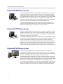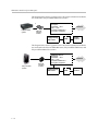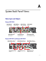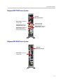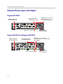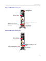
1
product pic here
Administrator’s Guide
for Polycom® HDX Systems
Version 2.5
December 2008 Edition
3725-23977-005/A
Version 2.5
Trademark Information
Polycom®, the Polycom logo design, ReadiManager® SE200, SoundStation®, ViewStation®, Vortex®, and VSX® are
registered trademarks of Polycom, Inc. Global Management System™, Instructor™ FS, iPower™, PathNavigator™,
People+Content™, People on Content™, Polycom Converged Management Application™ (CMA™), Polycom
EagleEye™, Polycom HDX 4000™, Polycom HDX 7000™, Polycom HDX 8000™, Polycom HDX 9000™, Polycom
HDX 9001™, Polycom HDX 9002™, Polycom HDX 9004™, Polycom MGC™, Polycom RMX 1000™, Polycom RMX
2000™, Polycom RSS™ 2000, Polycom Video Border Proxy™ (VBP™), PowerCam™, SoundStructure™,
StereoSurround™, and VS4000™ are trademarks of Polycom, Inc. in the United States and various other countries. All
other trademarks are the property of their respective owners.
Patent Information
The accompanying product is protected by one or more U.S. and foreign patents and/or pending patent applications
held by Polycom, Inc.
© 2008 Polycom, Inc. All rights reserved.
Polycom Inc.
4750 Willow Road
Pleasanton, CA 94588-2708
USA
No part of this document may be reproduced or transmitted in any form or by any means, electronic or mechanical, for
any purpose, without the express written permission of Polycom, Inc. Under the law, reproducing includes translating
into another language or format.
As between the parties, Polycom, Inc. retains title to, and ownership of, all proprietary rights with respect to the software
contained within its products. The software is protected by United States copyright laws and international treaty
provision. Therefore, you must treat the software like any other copyrighted material (e.g. a book or sound recording).
Every effort has been made to ensure that the information in this manual is accurate. Polycom, Inc. is not responsible
for printing or clerical errors. Information in this document is subject to change without notice.
About This Guide
The Administrator’s Guide for Polycom HDX Systems is for administrators who
need to configure, customize, manage, and troubleshoot Polycom® HDX
systems. The guide covers the Polycom HDX 9000™ series, Polycom HDX
8000™ series, Polycom HDX 7000™ series, and Polycom HDX 4000™ series
systems.
Please read the Polycom HDX system documentation before you install or
operate the system. The following related documents for Polycom HDX
systems are available at www.polycom.com/videodocumentation:
•
Setting Up the System, which describes how to set up the hardware
•
User’s Guide for Polycom HDX Systems, which describes how to perform
video conferencing tasks
•
Setup Sheets for your optional hardware
•
Release Notes
•
Integrator’s Reference Manual for Polycom HDX Systems, which provides
cable information and API command descriptions
For support or service, please contact your Polycom distributor or go to
Polycom Support at www.polycom.com/support.
Polycom recommends that you record the serial number and option key of
your Polycom HDX system here for future reference. The serial number for the
system is printed on the unit.
System Serial Number: ____________________________________________
Option Key: ____________________________________________________
iii
Administrator’s Guide for Polycom HDX Systems
iv
Contents
1 Introducing the Polycom HDX Systems . . . . . . . . . . . . . . . . 1-1
Polycom HDX Systems . . . . . . . . . . . . . . . . . . . . . . . . . . . . . . . . . . . . . . . . . . . . . . . . . . . . . . . . . 1-1
Polycom HDX 9000 Series Systems . . . . . . . . . . . . . . . . . . . . . . . . . . . . . . . . . . . . . . . . . . . 1-1
Polycom HDX 8000 Series Systems . . . . . . . . . . . . . . . . . . . . . . . . . . . . . . . . . . . . . . . . . . . 1-2
Polycom HDX 7000 Series Systems . . . . . . . . . . . . . . . . . . . . . . . . . . . . . . . . . . . . . . . . . . . 1-2
Polycom HDX 4000 Series Systems . . . . . . . . . . . . . . . . . . . . . . . . . . . . . . . . . . . . . . . . . . . 1-2
Setting Up Your System Hardware . . . . . . . . . . . . . . . . . . . . . . . . . . . . . . . . . . . . . . . . . . . . . . . 1-3
Positioning the System . . . . . . . . . . . . . . . . . . . . . . . . . . . . . . . . . . . . . . . . . . . . . . . . . . . . . . . . . . 1-3
Positioning the Polycom HDX 9000 Series Systems . . . . . . . . . . . . . . . . . . . . . . . . . . . . . 1-3
Positioning the Polycom HDX 8000 Series or Polycom HDX 7000 Series Systems . . . . 1-4
Positioning the Polycom HDX 4000 Series Systems . . . . . . . . . . . . . . . . . . . . . . . . . . . . . 1-5
Powering On and Off . . . . . . . . . . . . . . . . . . . . . . . . . . . . . . . . . . . . . . . . . . . . . . . . . . . . . . . . . . . 1-6
Powering On the Polycom HDX 9000 Series Systems . . . . . . . . . . . . . . . . . . . . . . . . . . . . 1-6
Powering On the Polycom HDX 8000 Series or Polycom HDX 7000 Series Systems . . 1-7
Powering On the Polycom HDX 4000 Series Systems . . . . . . . . . . . . . . . . . . . . . . . . . . . . 1-8
Configuring the Polycom HDX System . . . . . . . . . . . . . . . . . . . . . . . . . . . . . . . . . . . . . . . . . . . 1-10
Setup Wizard . . . . . . . . . . . . . . . . . . . . . . . . . . . . . . . . . . . . . . . . . . . . . . . . . . . . . . . . . . . . . 1-10
Admin Settings . . . . . . . . . . . . . . . . . . . . . . . . . . . . . . . . . . . . . . . . . . . . . . . . . . . . . . . . . . . 1-11
2 Networks . . . . . . . . . . . . . . . . . . . . . . . . . . . . . . . . . . . . . 2-1
Getting the Network Ready . . . . . . . . . . . . . . . . . . . . . . . . . . . . . . . . . . . . . . . . . . . . . . . . . . . . . 2-1
Connecting to the LAN . . . . . . . . . . . . . . . . . . . . . . . . . . . . . . . . . . . . . . . . . . . . . . . . . . . . . . . . . 2-1
LAN Status Lights . . . . . . . . . . . . . . . . . . . . . . . . . . . . . . . . . . . . . . . . . . . . . . . . . . . . . . . . . . 2-2
Configuring LAN Properties . . . . . . . . . . . . . . . . . . . . . . . . . . . . . . . . . . . . . . . . . . . . . . . . . 2-2
Configuring IP Settings . . . . . . . . . . . . . . . . . . . . . . . . . . . . . . . . . . . . . . . . . . . . . . . . . . . . . 2-6
Specifying H.323 Settings . . . . . . . . . . . . . . . . . . . . . . . . . . . . . . . . . . . . . . . . . . . . . . . 2-6
Configuring the System to Use a Gatekeeper . . . . . . . . . . . . . . . . . . . . . . . . . . . . . . . 2-7
Configuring Integration with Avaya Networks . . . . . . . . . . . . . . . . . . . . . . . . . . . . . 2-8
Configuring the System to Use a Gateway . . . . . . . . . . . . . . . . . . . . . . . . . . . . . . . . 2-10
Specifying SIP Settings . . . . . . . . . . . . . . . . . . . . . . . . . . . . . . . . . . . . . . . . . . . . . . . . . . . . . 2-11
Configuring Integration with Microsoft OCS . . . . . . . . . . . . . . . . . . . . . . . . . . . . . . 2-12
Specifying Quality of Service . . . . . . . . . . . . . . . . . . . . . . . . . . . . . . . . . . . . . . . . . . . . . . . 2-13
Configuring the System for Use with a Firewall or NAT . . . . . . . . . . . . . . . . . . . . . . . . 2-14
Firewall Settings . . . . . . . . . . . . . . . . . . . . . . . . . . . . . . . . . . . . . . . . . . . . . . . . . . . . . . 2-14
H.460 NAT Firewall Traversal . . . . . . . . . . . . . . . . . . . . . . . . . . . . . . . . . . . . . . . . . . 2-16
Connecting Polycom HDX Systems to ISDN or Other Networks . . . . . . . . . . . . . . . . . . . . . 2-17
v
Administrator’s Guide Polycom HDX Systems
Quad BRI Network Interface Status Lights . . . . . . . . . . . . . . . . . . . . . . . . . . . . . . . . . . . .
PRI Network Interface Status Lights . . . . . . . . . . . . . . . . . . . . . . . . . . . . . . . . . . . . . . . . .
Serial V.35/RS-449/RS-530 Network Interface Status Lights . . . . . . . . . . . . . . . . . . . .
Configuring ISDN and Other Network Interface Settings . . . . . . . . . . . . . . . . . . . . . . . . . . .
Configuring the BRI Network Interface . . . . . . . . . . . . . . . . . . . . . . . . . . . . . . . . . . . . . .
Configuring the PRI Network Interface . . . . . . . . . . . . . . . . . . . . . . . . . . . . . . . . . . . . . .
Configuring the Serial V.35/RS-449/RS-530 Network Interface . . . . . . . . . . . . . . . . . .
Connecting to an Analog Phone Line . . . . . . . . . . . . . . . . . . . . . . . . . . . . . . . . . . . . . . . . . . . .
Configuring Telephony . . . . . . . . . . . . . . . . . . . . . . . . . . . . . . . . . . . . . . . . . . . . . . . . . . . . . . . .
Configuring Call Preferences . . . . . . . . . . . . . . . . . . . . . . . . . . . . . . . . . . . . . . . . . . . . . . . . . . .
Configuring Dialing Order Settings . . . . . . . . . . . . . . . . . . . . . . . . . . . . . . . . . . . . . . . . . . . . . .
2-19
2-19
2-20
2-20
2-20
2-22
2-25
2-27
2-28
2-29
2-32
3 Monitors and Cameras . . . . . . . . . . . . . . . . . . . . . . . . . . . 3-1
Connecting Monitors . . . . . . . . . . . . . . . . . . . . . . . . . . . . . . . . . . . . . . . . . . . . . . . . . . . . . . . . . . . 3-1
Connecting Monitors to Polycom HDX 9000 Series Systems . . . . . . . . . . . . . . . . . . . . . . 3-1
Connecting Monitors to Polycom HDX 8000 Series or
Polycom HDX 7000 Series Systems . . . . . . . . . . . . . . . . . . . . . . . . . . . . . . . . . . . . . . . . . . . 3-2
Using a Polycom HDX 4000 Series Monitor with a Computer . . . . . . . . . . . . . . . . . . . . 3-2
Configuring Monitor Settings . . . . . . . . . . . . . . . . . . . . . . . . . . . . . . . . . . . . . . . . . . . . . . . . . . . . 3-3
Using Dual Monitor Emulation . . . . . . . . . . . . . . . . . . . . . . . . . . . . . . . . . . . . . . . . . . . . . . 3-9
Examples of Dual Monitor Emulation . . . . . . . . . . . . . . . . . . . . . . . . . . . . . . . . . . . . . 3-9
Using Dual Monitor Emulation in a Call . . . . . . . . . . . . . . . . . . . . . . . . . . . . . . . . . . 3-9
Configuring Multipoint Viewing Modes . . . . . . . . . . . . . . . . . . . . . . . . . . . . . . . . . . . . . 3-10
Adjusting the Monitor’s Color Balance, Sharpness, and Brightness . . . . . . . . . . . . . . . 3-11
Preventing Monitor Burn-In . . . . . . . . . . . . . . . . . . . . . . . . . . . . . . . . . . . . . . . . . . . . . . . . 3-12
Connecting Cameras . . . . . . . . . . . . . . . . . . . . . . . . . . . . . . . . . . . . . . . . . . . . . . . . . . . . . . . . . . 3-13
Connecting Cameras to Polycom HDX 9000 Series Systems . . . . . . . . . . . . . . . . . . . . . 3-14
Connecting Cameras to Polycom HDX 8000 Series Systems . . . . . . . . . . . . . . . . . . . . . 3-15
Connecting Cameras to Polycom HDX 7000 Series Systems . . . . . . . . . . . . . . . . . . . . . 3-15
Connecting Cameras to Polycom HDX 4000 Series Systems . . . . . . . . . . . . . . . . . . . . . 3-15
Configuring Camera Settings and Video Quality Options . . . . . . . . . . . . . . . . . . . . . . . . . . . 3-16
Configuring Advanced Polycom EagleEye HD Camera Settings . . . . . . . . . . . . . . . . . . . . . 3-22
Configuring Camera Presets . . . . . . . . . . . . . . . . . . . . . . . . . . . . . . . . . . . . . . . . . . . . . . . . . . . . 3-24
Experiencing High-Definition Video Conferencing . . . . . . . . . . . . . . . . . . . . . . . . . . . . . . . . 3-25
Sending Video in High Definition . . . . . . . . . . . . . . . . . . . . . . . . . . . . . . . . . . . . . . . . . . . 3-25
Receiving and Displaying Video in High Definition . . . . . . . . . . . . . . . . . . . . . . . . . . . . 3-26
HD and SD Multipoint Calls . . . . . . . . . . . . . . . . . . . . . . . . . . . . . . . . . . . . . . . . . . . . . . . . 3-26
4 Microphones and Speakers . . . . . . . . . . . . . . . . . . . . . . . . 4-1
Connecting Audio Input . . . . . . . . . . . . . . . . . . . . . . . . . . . . . . . . . . . . . . . . . . . . . . . . . . . . . . . .
Connecting Audio Input to Polycom HDX 9000 Series Systems . . . . . . . . . . . . . . . . . . .
Connecting Audio Input to Polycom HDX 8000 Series Systems . . . . . . . . . . . . . . . . . . .
Connecting Audio Input to Polycom HDX 7000 Series Systems . . . . . . . . . . . . . . . . . . .
Connecting Devices to the Polycom HDX Microphone Input . . . . . . . . . . . . . . . . . . . . .
Connecting Devices to the Polycom HDX 9000 Series Microphone Input . . . . . . .
Connecting Devices to the Polycom HDX 8000 Series Microphone Input . . . . . . .
vi
4-1
4-1
4-2
4-2
4-2
4-3
4-4
Contents
Connecting Devices to the Polycom HDX 7000 Series Microphone Input . . . . . . . 4-5
Connecting Devices to the Polycom HDX 4000 Series Microphone Input . . . . . . . 4-5
Placing Polycom Microphones to Send Stereo from Your Site . . . . . . . . . . . . . . . . . . . . 4-6
Polycom Microphone Lights . . . . . . . . . . . . . . . . . . . . . . . . . . . . . . . . . . . . . . . . . . . . . . . . . 4-7
Connecting Non-Polycom Microphones or a Mixer to a Polycom HDX System . . . . . 4-7
Connecting Audio Output . . . . . . . . . . . . . . . . . . . . . . . . . . . . . . . . . . . . . . . . . . . . . . . . . . . . . . . 4-8
Connecting Speakers to Polycom HDX 9000 Series Systems . . . . . . . . . . . . . . . . . . . . . . 4-9
Connecting Speakers to Polycom HDX 8000 Series or
Polycom HDX 7000 Series Systems . . . . . . . . . . . . . . . . . . . . . . . . . . . . . . . . . . . . . . . . . . . 4-9
Connecting Speakers or Headphones to Polycom HDX 4000 Series Systems . . . . . . . . 4-9
Placing Speakers to Play Stereo from Far Sites . . . . . . . . . . . . . . . . . . . . . . . . . . . . . . . . . 4-10
Setting the Speaker Volume . . . . . . . . . . . . . . . . . . . . . . . . . . . . . . . . . . . . . . . . . . . . . . . . 4-11
Configuring Audio Settings . . . . . . . . . . . . . . . . . . . . . . . . . . . . . . . . . . . . . . . . . . . . . . . . . . . . 4-11
General Audio Settings . . . . . . . . . . . . . . . . . . . . . . . . . . . . . . . . . . . . . . . . . . . . . . . . . . . . 4-11
StereoSurround Settings . . . . . . . . . . . . . . . . . . . . . . . . . . . . . . . . . . . . . . . . . . . . . . . . . . . 4-15
Audio Meters . . . . . . . . . . . . . . . . . . . . . . . . . . . . . . . . . . . . . . . . . . . . . . . . . . . . . . . . . . . . . 4-16
Testing StereoSurround . . . . . . . . . . . . . . . . . . . . . . . . . . . . . . . . . . . . . . . . . . . . . . . . . . . . 4-17
Polycom HDX System Settings for a Polycom Vortex Mixer . . . . . . . . . . . . . . . . . . . . . 4-18
Settings for Non-Polycom Microphones . . . . . . . . . . . . . . . . . . . . . . . . . . . . . . . . . . . . . . 4-18
5 Content and Closed Captions . . . . . . . . . . . . . . . . . . . . . . . 5-1
Connecting VCR/DVDs . . . . . . . . . . . . . . . . . . . . . . . . . . . . . . . . . . . . . . . . . . . . . . . . . . . . . . . .
Configuring VCR/DVD Player Settings . . . . . . . . . . . . . . . . . . . . . . . . . . . . . . . . . . . . . . . . . . .
Playing a Videotape or DVD . . . . . . . . . . . . . . . . . . . . . . . . . . . . . . . . . . . . . . . . . . . . . . . .
Recording a Call to Videotape or DVD . . . . . . . . . . . . . . . . . . . . . . . . . . . . . . . . . . . . . . . .
Connecting Computers to Polycom HDX Systems . . . . . . . . . . . . . . . . . . . . . . . . . . . . . . . . . .
Configuring Content Sharing . . . . . . . . . . . . . . . . . . . . . . . . . . . . . . . . . . . . . . . . . . . . . . . . . . . .
Configuring Content Display with People+Content IP . . . . . . . . . . . . . . . . . . . . . . . . . . . . . .
Configuring People on Content™ . . . . . . . . . . . . . . . . . . . . . . . . . . . . . . . . . . . . . . . . . . . . . . . .
Setting Up the Room for People on Content . . . . . . . . . . . . . . . . . . . . . . . . . . . . . . . . . . . .
Enabling and Calibrating People on Content on the System . . . . . . . . . . . . . . . . . . . . . .
Configuring Closed Captioning . . . . . . . . . . . . . . . . . . . . . . . . . . . . . . . . . . . . . . . . . . . . . . . . . .
Via a Dial-Up Connection to the Systems’ RS-232 Serial Port . . . . . . . . . . . . . . . . . . . . .
Via the System’s Serial RS-232 Port . . . . . . . . . . . . . . . . . . . . . . . . . . . . . . . . . . . . . . . . . . .
Via the Polycom HDX Web Interface . . . . . . . . . . . . . . . . . . . . . . . . . . . . . . . . . . . . . . . . . .
5-1
5-1
5-1
5-2
5-3
5-3
5-4
5-5
5-5
5-6
5-7
5-7
5-8
5-9
6 Calling and Answering . . . . . . . . . . . . . . . . . . . . . . . . . . . 6-1
Configuring Call Settings . . . . . . . . . . . . . . . . . . . . . . . . . . . . . . . . . . . . . . . . . . . . . . . . . . . . . . .
Setting the Call Answering Mode . . . . . . . . . . . . . . . . . . . . . . . . . . . . . . . . . . . . . . . . . . . . . . . .
Configuring Multipoint Calling . . . . . . . . . . . . . . . . . . . . . . . . . . . . . . . . . . . . . . . . . . . . . . . . . .
Entering a Multipoint Option Key . . . . . . . . . . . . . . . . . . . . . . . . . . . . . . . . . . . . . . . . . . . .
Configuring the Conference on Demand Feature . . . . . . . . . . . . . . . . . . . . . . . . . . . . . . .
Including Multiple Sites in a Cascaded Call . . . . . . . . . . . . . . . . . . . . . . . . . . . . . . . . . . . .
Configuring Directory Settings . . . . . . . . . . . . . . . . . . . . . . . . . . . . . . . . . . . . . . . . . . . . . . . . . . .
Creating a Localized System Name with the Polycom HDX Web Interface . . . . . . . . .
6-1
6-2
6-3
6-3
6-4
6-5
6-6
6-6
vii
Administrator’s Guide Polycom HDX Systems
Managing Directories with the Polycom HDX Web Interface . . . . . . . . . . . . . . . . . . . . . 6-7
Configuring the Global Directory . . . . . . . . . . . . . . . . . . . . . . . . . . . . . . . . . . . . . . . . . . . . . . . . 6-8
Directory Groups . . . . . . . . . . . . . . . . . . . . . . . . . . . . . . . . . . . . . . . . . . . . . . . . . . . . . . . . . . . . . 6-11
Global Directory Groups . . . . . . . . . . . . . . . . . . . . . . . . . . . . . . . . . . . . . . . . . . . . . . . . . . . 6-11
Local Directory Groups . . . . . . . . . . . . . . . . . . . . . . . . . . . . . . . . . . . . . . . . . . . . . . . . . . . . 6-12
7 System Location, Appearance, and Tones . . . . . . . . . . . . . . 7-1
Configuring Regional Settings . . . . . . . . . . . . . . . . . . . . . . . . . . . . . . . . . . . . . . . . . . . . . . . . . . .
Customizing the Home Screen . . . . . . . . . . . . . . . . . . . . . . . . . . . . . . . . . . . . . . . . . . . . . . . . . . .
Displaying Contacts and Speed Dial Sites . . . . . . . . . . . . . . . . . . . . . . . . . . . . . . . . . . . . .
Adding Marquee Text . . . . . . . . . . . . . . . . . . . . . . . . . . . . . . . . . . . . . . . . . . . . . . . . . . . . . .
Setting Ring Tones and Alert Tones . . . . . . . . . . . . . . . . . . . . . . . . . . . . . . . . . . . . . . . . . . . . . . .
Customizing Camera Names and Icons . . . . . . . . . . . . . . . . . . . . . . . . . . . . . . . . . . . . . . . . . . .
Screen Savers . . . . . . . . . . . . . . . . . . . . . . . . . . . . . . . . . . . . . . . . . . . . . . . . . . . . . . . . . . . . . . . . . .
Adding Screen Saver Text . . . . . . . . . . . . . . . . . . . . . . . . . . . . . . . . . . . . . . . . . . . . . . . . . . .
Adding a Screen Saver Logo . . . . . . . . . . . . . . . . . . . . . . . . . . . . . . . . . . . . . . . . . . . . . . . . .
7-1
7-3
7-6
7-6
7-7
7-7
7-8
7-8
7-9
8 Security . . . . . . . . . . . . . . . . . . . . . . . . . . . . . . . . . . . . . . 8-1
Screens that Require a Password for Access . . . . . . . . . . . . . . . . . . . . . . . . . . . . . . . . . . . . . . . . 8-1
Configuring Security Options . . . . . . . . . . . . . . . . . . . . . . . . . . . . . . . . . . . . . . . . . . . . . . . . . . . . 8-2
Configuring Security Mode . . . . . . . . . . . . . . . . . . . . . . . . . . . . . . . . . . . . . . . . . . . . . . . . . . . . . . 8-4
Enabling a Security Profile . . . . . . . . . . . . . . . . . . . . . . . . . . . . . . . . . . . . . . . . . . . . . . . . . . 8-6
Enabling AES Encryption . . . . . . . . . . . . . . . . . . . . . . . . . . . . . . . . . . . . . . . . . . . . . . . . . . . . . . . 8-7
Setting Password Policies . . . . . . . . . . . . . . . . . . . . . . . . . . . . . . . . . . . . . . . . . . . . . . . . . . . . . . . 8-7
Setting the Room and Remote Access Passwords . . . . . . . . . . . . . . . . . . . . . . . . . . . . . . . . . . . 8-9
Setting an Account Lockout . . . . . . . . . . . . . . . . . . . . . . . . . . . . . . . . . . . . . . . . . . . . . . . . . . . . 8-10
Managing User Access to Settings and Features . . . . . . . . . . . . . . . . . . . . . . . . . . . . . . . . . . . 8-11
Setting up Log Management . . . . . . . . . . . . . . . . . . . . . . . . . . . . . . . . . . . . . . . . . . . . . . . . . . . . 8-12
9 Managing the System Remotely . . . . . . . . . . . . . . . . . . . . . 9-1
Using the Polycom HDX Web Interface . . . . . . . . . . . . . . . . . . . . . . . . . . . . . . . . . . . . . . . . . . .
Accessing the Polycom HDX Web Interface . . . . . . . . . . . . . . . . . . . . . . . . . . . . . . . . . . . .
Monitoring a Room or Call with the Polycom HDX Web Interface . . . . . . . . . . . . . . . .
Managing System Profiles with the Polycom HDX Web Interface . . . . . . . . . . . . . . . . .
Sending a Message . . . . . . . . . . . . . . . . . . . . . . . . . . . . . . . . . . . . . . . . . . . . . . . . . . . . . . . . .
Configuring Global Services . . . . . . . . . . . . . . . . . . . . . . . . . . . . . . . . . . . . . . . . . . . . . . . . . . . . .
Viewing the Management Servers List . . . . . . . . . . . . . . . . . . . . . . . . . . . . . . . . . . . . . . . .
Requiring an Account Number for Calls . . . . . . . . . . . . . . . . . . . . . . . . . . . . . . . . . . . . . . .
Adding Information for the Global Management System Administrator . . . . . . . . . . .
Requesting Technical Support from the Global Management
System Administrator . . . . . . . . . . . . . . . . . . . . . . . . . . . . . . . . . . . . . . . . . . . . . . . . . . . . . .
Setting Up SNMP . . . . . . . . . . . . . . . . . . . . . . . . . . . . . . . . . . . . . . . . . . . . . . . . . . . . . . . . . .
Downloading MIBs . . . . . . . . . . . . . . . . . . . . . . . . . . . . . . . . . . . . . . . . . . . . . . . . . . . . .
Configuring for SNMP Management . . . . . . . . . . . . . . . . . . . . . . . . . . . . . . . . . . . . . .
Configuring a Provisioning Service . . . . . . . . . . . . . . . . . . . . . . . . . . . . . . . . . . . . . . . . . . .
viii
9-1
9-1
9-2
9-3
9-4
9-4
9-4
9-5
9-5
9-6
9-6
9-6
9-7
9-7
Contents
Keeping your Software Current . . . . . . . . . . . . . . . . . . . . . . . . . . . . . . . . . . . . . . . . . . . . . . . . . . 9-9
10 Control Devices . . . . . . . . . . . . . . . . . . . . . . . . . . . . . . . . 10-1
Configuring Remote Control Behavior . . . . . . . . . . . . . . . . . . . . . . . . . . . . . . . . . . . . . . . . . . .
Configuring the Remote Control Channel ID . . . . . . . . . . . . . . . . . . . . . . . . . . . . . . . . . .
Configuring the Remote to Control a Recording Device . . . . . . . . . . . . . . . . . . . . . . . .
Connecting Control and Accessibility Equipment . . . . . . . . . . . . . . . . . . . . . . . . . . . . . . . . . .
Connecting Touch-Panel Controls . . . . . . . . . . . . . . . . . . . . . . . . . . . . . . . . . . . . . . . . . . .
Connecting IR Sensors to Polycom HDX Systems . . . . . . . . . . . . . . . . . . . . . . . . . . . . . .
Configuring RS-232 Serial Port Settings . . . . . . . . . . . . . . . . . . . . . . . . . . . . . . . . . . . . . . . . . .
10-1
10-2
10-3
10-3
10-4
10-4
10-5
11 Statistics and Diagnostics . . . . . . . . . . . . . . . . . . . . . . . . . 11-1
Diagnostic Screens . . . . . . . . . . . . . . . . . . . . . . . . . . . . . . . . . . . . . . . . . . . . . . . . . . . . . . . . . . . . 11-1
System Status . . . . . . . . . . . . . . . . . . . . . . . . . . . . . . . . . . . . . . . . . . . . . . . . . . . . . . . . . . . . . 11-2
Server Status . . . . . . . . . . . . . . . . . . . . . . . . . . . . . . . . . . . . . . . . . . . . . . . . . . . . . . . . . . . . . 11-2
Call Statistics . . . . . . . . . . . . . . . . . . . . . . . . . . . . . . . . . . . . . . . . . . . . . . . . . . . . . . . . . . . . . 11-3
Network . . . . . . . . . . . . . . . . . . . . . . . . . . . . . . . . . . . . . . . . . . . . . . . . . . . . . . . . . . . . . . . . . 11-5
Video . . . . . . . . . . . . . . . . . . . . . . . . . . . . . . . . . . . . . . . . . . . . . . . . . . . . . . . . . . . . . . . . . . . . 11-5
Audio . . . . . . . . . . . . . . . . . . . . . . . . . . . . . . . . . . . . . . . . . . . . . . . . . . . . . . . . . . . . . . . . . . . 11-6
Reset or Restart System . . . . . . . . . . . . . . . . . . . . . . . . . . . . . . . . . . . . . . . . . . . . . . . . . . . . 11-7
Recent Calls . . . . . . . . . . . . . . . . . . . . . . . . . . . . . . . . . . . . . . . . . . . . . . . . . . . . . . . . . . . . . . . . . . 11-7
Call Detail Report (CDR) . . . . . . . . . . . . . . . . . . . . . . . . . . . . . . . . . . . . . . . . . . . . . . . . . . . . . . . 11-8
Information in the CDR . . . . . . . . . . . . . . . . . . . . . . . . . . . . . . . . . . . . . . . . . . . . . . . . . . . . 11-8
Call Detail Report Archives . . . . . . . . . . . . . . . . . . . . . . . . . . . . . . . . . . . . . . . . . . . . . . . . 11-11
System Logs . . . . . . . . . . . . . . . . . . . . . . . . . . . . . . . . . . . . . . . . . . . . . . . . . . . . . . . . . . . . . . . . . 11-12
Downloading System Logs from the Polycom HDX Web Interface . . . . . . . . . . . . . . 11-12
System Log Settings in the Polycom HDX Web Interface . . . . . . . . . . . . . . . . . . . . . . 11-12
12 Troubleshooting . . . . . . . . . . . . . . . . . . . . . . . . . . . . . . . 12-1
Placing a Test Call . . . . . . . . . . . . . . . . . . . . . . . . . . . . . . . . . . . . . . . . . . . . . . . . . . . . . . . . . . . . .
Enabling Basic Mode . . . . . . . . . . . . . . . . . . . . . . . . . . . . . . . . . . . . . . . . . . . . . . . . . . . . . . . . . .
Using the Restore Button . . . . . . . . . . . . . . . . . . . . . . . . . . . . . . . . . . . . . . . . . . . . . . . . . . . . . . .
Restoring Configuration . . . . . . . . . . . . . . . . . . . . . . . . . . . . . . . . . . . . . . . . . . . . . . . . . . .
Factory Restore . . . . . . . . . . . . . . . . . . . . . . . . . . . . . . . . . . . . . . . . . . . . . . . . . . . . . . . . . . .
How to Contact Technical Support . . . . . . . . . . . . . . . . . . . . . . . . . . . . . . . . . . . . . . . . . . . . . .
12-1
12-2
12-2
12-3
12-4
12-4
Regulatory Notices . . . . . . . . . . . . . . . . . Regulatory Notices-1
A System Back Panel Views . . . . . . . . . . . . . . . . . . . . . . . . . A-1
Video Inputs and Outputs . . . . . . . . . . . . . . . . . . . . . . . . . . . . . . . . . . . . . . . . . . . . . . . . . . . . . .
Polycom HDX 9004 . . . . . . . . . . . . . . . . . . . . . . . . . . . . . . . . . . . . . . . . . . . . . . . . . . . . . . . .
Polycom HDX 9001 and Polycom HDX 9002 . . . . . . . . . . . . . . . . . . . . . . . . . . . . . . . . . .
Polycom HDX 8000 Series System . . . . . . . . . . . . . . . . . . . . . . . . . . . . . . . . . . . . . . . . . . .
A-1
A-1
A-1
A-2
ix
Administrator’s Guide Polycom HDX Systems
Polycom HDX 7000 Series System . . . . . . . . . . . . . . . . . . . . . . . . . . . . . . . . . . . . . . . . . . .
Polycom HDX 4000 Series System . . . . . . . . . . . . . . . . . . . . . . . . . . . . . . . . . . . . . . . . . . .
Audio Inputs and Outputs . . . . . . . . . . . . . . . . . . . . . . . . . . . . . . . . . . . . . . . . . . . . . . . . . . . . .
Polycom HDX 9004 . . . . . . . . . . . . . . . . . . . . . . . . . . . . . . . . . . . . . . . . . . . . . . . . . . . . . . . .
Polycom HDX 9001 and Polycom HDX 9002 . . . . . . . . . . . . . . . . . . . . . . . . . . . . . . . . . .
Polycom HDX 8000 Series System . . . . . . . . . . . . . . . . . . . . . . . . . . . . . . . . . . . . . . . . . . .
Polycom HDX 7000 Series System . . . . . . . . . . . . . . . . . . . . . . . . . . . . . . . . . . . . . . . . . . .
Polycom HDX 4000 Series System . . . . . . . . . . . . . . . . . . . . . . . . . . . . . . . . . . . . . . . . . . .
Network/Power Inputs and Outputs . . . . . . . . . . . . . . . . . . . . . . . . . . . . . . . . . . . . . . . . . . . .
Polycom HDX 9004 . . . . . . . . . . . . . . . . . . . . . . . . . . . . . . . . . . . . . . . . . . . . . . . . . . . . . . . .
Polycom HDX 9001 and Polycom HDX 9002 . . . . . . . . . . . . . . . . . . . . . . . . . . . . . . . . . .
Polycom HDX 8000 Series System . . . . . . . . . . . . . . . . . . . . . . . . . . . . . . . . . . . . . . . . . . .
Polycom HDX 7000 Series System . . . . . . . . . . . . . . . . . . . . . . . . . . . . . . . . . . . . . . . . . . .
Polycom HDX 4000 Series System . . . . . . . . . . . . . . . . . . . . . . . . . . . . . . . . . . . . . . . . . . .
A-2
A-3
A-3
A-3
A-4
A-4
A-5
A-5
A-6
A-6
A-6
A-7
A-7
A-8
B Port Usage . . . . . . . . . . . . . . . . . . . . . . . . . . . . . . . . . . . . B-1
C Multipoint Dialing Speeds and Call Speed Resolutions . . . . C-1
Multipoint Dialing Speeds . . . . . . . . . . . . . . . . . . . . . . . . . . . . . . . . . . . . . . . . . . . . . . . . . . . . . . . C-1
Call Speeds and Resolutions . . . . . . . . . . . . . . . . . . . . . . . . . . . . . . . . . . . . . . . . . . . . . . . . . . . . . C-3
HD Systems (NTSC) . . . . . . . . . . . . . . . . . . . . . . . . . . . . . . . . . . . . . . . . . . . . . . . . . . . . . . . . C-3
SD Systems (NTSC) . . . . . . . . . . . . . . . . . . . . . . . . . . . . . . . . . . . . . . . . . . . . . . . . . . . . . . . . C-4
1080p Systems (NTSC) . . . . . . . . . . . . . . . . . . . . . . . . . . . . . . . . . . . . . . . . . . . . . . . . . . . . . . C-5
D Codes for Remote Control Recording Device Buttons . . . . . . D-1
DVD Player Codes . . . . . . . . . . . . . . . . . . . . . . . . . . . . . . . . . . . . . . . . . . . . . . . . . . . . . . . . . . . .
DVD Recorder Codes . . . . . . . . . . . . . . . . . . . . . . . . . . . . . . . . . . . . . . . . . . . . . . . . . . . . . . . . . .
VCR Device Codes . . . . . . . . . . . . . . . . . . . . . . . . . . . . . . . . . . . . . . . . . . . . . . . . . . . . . . . . . . . .
PVR Device Codes . . . . . . . . . . . . . . . . . . . . . . . . . . . . . . . . . . . . . . . . . . . . . . . . . . . . . . . . . . . .
D-1
D-2
D-3
D-5
Index . . . . . . . . . . . . . . . . . . . . . . . . . . . . . . . . . . . . . Index-1
x
1
Introducing the Polycom HDX
Systems
Your Polycom HDX video conferencing system is a state-of-the-art visual
collaboration tool. With crisp, clean video and crystal-clear sound, Polycom
HDX systems provide natural video conferencing interaction through the
most advanced video communications technology.
Polycom HDX Systems
For technical specifications and detailed descriptions of features available for
Polycom HDX models, please refer to the product literature available at
www.polycom.com.
Polycom HDX 9000 Series Systems
The Polycom HDX 9000 series provides integrator-class connectors and
supports multiple video and audio sources. These solutions allow integrators
to create specialized and unique, real-time video environments for their
customers. The Polycom HDX 9000 series includes three models: Polycom
HDX 9004™, Polycom HDX 9002™, and Polycom HDX 9001™.
The Polycom HDX 9004 and Polycom HDX 9002 systems can send and receive
wide-screen, high-definition (HD) video in point-to-point and multipoint
calls. The Polycom HDX 9001 sends and receives up to 480p (NTSC) or 576
(PAL), standard-definition video.
1-1
Administrator’s Guide for Polycom HDX Systems
Polycom HDX 8000 Series Systems
The Polycom HDX 8000 series provides high-definition (HD) voice, video, and
content for medium to large conference rooms. These systems incorporate
leading-edge design with performance, flexibility, and capabilities, making it
an optimal solution for meeting spaces in any organization. The Polycom HDX
8000 series systems can send and receive wide-screen, HD 720p video in
point-to-point and multipoint calls. Polycom HDX 8000 series systems with
hardware version B can send and receive full HD (1080p) video.
The Polycom HDX 8000 series systems ship with a Polycom EagleEye™
camera, Polycom HDX microphones, and a Polycom HDX remote control.
Bundles including displays and furniture are also available.
Polycom HDX 7000 Series Systems
The Polycom HDX 7000 series provides voice, video, and content for small to
medium conference rooms. These systems incorporate leading-edge design
with performance, flexibility, and capabilities, making it an optimal solution
for meeting spaces in any organization.
The Polycom HDX 7000 series has two models: the Polycom HDX 7000 system
and the Polycom HDX 7000 HD system. The Polycom HDX 7000 HD system is
an HD system that sends and receives HD video in point-to-point and
multipoint calls. The Polycom HDX 7000 system is an SD system that sends
and receives video in 4CIF/4SIF resolutions. Both models include a Polycom
EagleEye HD camera, Polycom HDX microphones, and a Polycom HDX
remote control. Bundles including displays and furniture are also available.
Polycom HDX 4000 Series Systems
The Polycom HDX 4000 series provides the ultimate in desktop video
conferencing, designed to allow today’s professionals to be more productive
and effective right from their office. With a 20.1” LCD screen, powerful stereo
speakers, and sleek design, these systems are much more than
communications devices; they are also fully functional monitors for your PC
or MAC. The Polycom HDX 4000 series has two models: the Polycom HDX
4000 system and the Polycom HDX 4000 HD system. The Polycom HDX 4000
HD system is an HD system that sends and receives HD 720p video in
point-to-point and multipoint calls. The Polycom HDX 4000 system is an SD
system that sends and receives video in 4CIF/4SIF resolutions. Both models
include an HD built-in PTZ camera, four speakers, and dual microphones.
1-2
Introducing the Polycom HDX Systems
Setting Up Your System Hardware
This manual provides information to supplement the setup sheets provided
with your system and its optional components. A printed copy of the system
setup sheet is provided with each Polycom HDX system. PDF versions of the
system setup sheets are available at
www.polycom.com/videodocumentation.
Positioning the System
Positioning the Polycom HDX 9000 Series Systems
Polycom HDX 9000 series systems are designed to be placed on a tabletop or
in an equipment rack.
To position the system:
1. Install the mounting brackets on the system if you need to mount it in an
equipment rack, or install the self-adhesive feet if you will place the
system on a table or shelf.
2. Place the system in the desired location. Position the system so that the
camera does not face toward a window or other source of bright light.
Leave enough space to connect the cables easily. Place the camera and
display together so that people at your site face the camera when they are
looking at the display.
1-3
Administrator’s Guide for Polycom HDX Systems
Positioning the Polycom HDX 8000 Series or Polycom HDX 7000 Series
Systems
Polycom HDX 8000 series and Polycom HDX 7000 series systems can be set up
in multiple ways. When used with furniture such as a pedestal or wall mount,
the system fits into a bracket on the back of the display. The system can also be
placed in a cart or on a table.
To position the system:
¾
Position the system so that the camera does not face toward a window or
other source of bright light. Leave enough space to connect the cables
easily. Place the camera and display together so that people at your site
face the camera when they are looking at the display.
If you need to position the system horizontally, remove the stand and install
the self-adhesive feet.
Caution. Risk of Electric Shock. To reduce the risk of personal injury or damage to
the equipment, do not use screws longer than those supplied (M4x16, 8.00 mm
maximum head diameter) to reconnect the stand to the system.
1-4
Introducing the Polycom HDX Systems
Positioning the Polycom HDX 4000 Series Systems
The Polycom HDX 4000 series systems are personal video conferencing
systems for the desktop.
To position the system:
1. Place the Polycom HDX 4000 series monitor on the desktop, leaving
enough space to connect the cables easily. Position the system so that the
camera does not face toward a window or other source of bright light.
2. Place the Polycom HDX 4000 series system either under the desk, or on
the desk next to the display. The cables that connect the display to the
system can be hidden in the monitor stand, providing clean cable
management.
If you need to position the system horizontally, remove the stand and install
the self-adhesive feet.
Caution. Risk of Electric Shock. To reduce the risk of personal injury or damage to
the equipment, do not use screws longer than those supplied (M4x16, 8.00 mm
maximum head diameter) to reconnect the stand to the system.
1-5
Administrator’s Guide for Polycom HDX Systems
Powering On and Off
Connect power and power on the system after you have connected all of the
equipment that you will use with it. Make sure that the system is powered off
before you connect devices to it.
Powering On the Polycom HDX 9000 Series Systems
To power on the Polycom HDX 9000 series, do one of the following:
•
Press the
power button on the remote control.
•
Press the power switch on the front of the system.
The Polycom splash screen is displayed within about 10 seconds.
To power off the Polycom HDX 9000 series, do one of the following:
•
Press and hold the
power button on the remote control for 2 seconds.
•
Press and hold the power switch on the front of the system for 2 seconds.
The following figure shows the location of the power switch and indicator
light.
1-6
Introducing the Polycom HDX Systems
The indicator light on the front of the Polycom HDX 9000 series system
provides this information:
Indicator Light
System Status
Off
System is powered off.
Steady green light
System is initializing.
System is awake and not in a call.
Blinking green light
System received an IR signal while
awake and not in a call.
Blinking green light (on 1 sec, off 2 sec)
System is asleep, not in a call.
Steady amber light
System is in a call.
Blinking amber light
System received an IR signal while in
a call.
Alternating green and amber lights
System is in software update mode.
System is in factory restore mode.
Powering On the Polycom HDX 8000 Series or Polycom HDX 7000 Series
Systems
To power on the Polycom HDX 8000 series or Polycom HDX 7000 series system,
do one of the following:
•
Press the
power button on the remote control.
•
Press the power switch on the front of the system.
The Polycom splash screen is displayed within about 10 seconds.
To power off the Polycom HDX 8000 series or Polycom HDX 7000 series system,
do one of the following:
•
Press and hold the
power button on the remote control for 2 seconds.
•
Press and hold the power switch on the front of the system for 2 seconds.
1-7
Administrator’s Guide for Polycom HDX Systems
The indicator light on the front of the Polycom HDX 8000 series and Polycom
HDX 7000 series system provides this information:
Indicator Light
System Status
Off
System is without power.
Steady blue light
System is initializing.
System is awake and not in a call.
Blinking blue light
System received an IR signal while
awake.
Blinking blue light (on 1 sec, off 2 sec)
System is asleep, not in a call.
Steady amber light
System is in a call.
Blinking amber light
System received an IR signal while in
a call.
Alternating blue and amber lights
System is in software update mode.
System is in factory restore mode.
Powering On the Polycom HDX 4000 Series Systems
To power on the Polycom HDX 4000 series, do one of the following:
•
Press the power button on the front of the system.
•
Press the power button on the side of the monitor.
The system powers on and displays near video or your computer desktop
within about 60 seconds.
To power off the Polycom HDX 4000 series monitor:
¾
Press the power button on the side of the monitor.
The monitor enters standby mode. The system stays powered on.
To power off the Polycom HDX 4000 series, do one of the following:
•
Press and hold the power button on the side of the monitor.
The monitor and the system power off.
•
Press and hold the power button on the front of the system.
The monitor and the system power off.
1-8
Introducing the Polycom HDX Systems
The following figure shows the location of the power switches and indicator
lights.
Monitor Power
Monitor Camera
System
The indicator light on the front of the Polycom HDX 4000 series system
provides this information:
Indicator Light (System)
Status
Off
System is without power.
Steady blue light
System is initializing.
System is awake and not in a call.
Blinking blue light
System received an IR signal while awake.
Blinking blue light (on 1 sec, off
2 sec)
System is asleep, not in a call.
Steady amber light
System is in a call.
Blinking amber light
System received an IR signal while in a
call.
Alternating blue and amber lights
System is in software update mode.
System is in factory restore mode.
1-9
Administrator’s Guide for Polycom HDX Systems
The indicator light on the side of the Polycom HDX 4000 series monitor
provides this information:
Indicator Light (Monitor Power)
Status
Off
Monitor is powered off.
Steady blue light
Monitor is powered on.
Steady amber light
Monitor is in standby mode.
Rapidly blinking light
Monitor is not connected correctly to the
system. Verify that the monitor is connected
correctly according to the setup sheet you
received with the system.
The indicator light next to the Polycom HDX 4000 series built-in camera
provides this information:
Indicator Light (Monitor Camera)
Status
Off
System is not in a call.
Steady green light
System is in a call.
Blinking green light
System is in a call with the privacy shutter
closed.
Configuring the Polycom HDX System
Setup Wizard
When you power on your system for the first time, the setup wizard detects
the system’s IP and ISDN connections and leads you through the minimum
configuration steps required to place a call.
The setup wizard allows you to set a room password, which allows you to
limit access to the Admin Settings. The default room password is the 14-digit
system serial number from the System Information screen or the back of the
system.
Make sure you can recall the room password if you set one. If you forget the
password, you will have to reset the system, delete the system files, and run the
setup wizard again in order to access the Admin Settings and reset the password.
If Security Mode is enabled, the room password is required to access the Reset
System screen. If you forget the room password while the system is in Security
Mode, refer to Using the Restore Button on page 12-2.
1 - 10
Introducing the Polycom HDX Systems
You can run the setup wizard or view the configuration screens in either of
these two ways.
•
In the room with the system — Use the remote control to navigate the
screens and enter information. You can use the number pad on the remote
control to enter text just like you can with a cell phone.
•
From a remote location — Use a web browser to access the Polycom HDX
Web Interface. For more information about using the web interface, refer
to Accessing the Polycom HDX Web Interface on page 9-1.
The setup wizard is available during initial setup, after a system update with
system settings not saved, or after a system reset with system settings deleted.
Admin Settings
After you run the setup wizard, you can view or change the system’s
configuration by going to the Admin Settings in the system’s local interface or
web interface.
If you enable a security profile in the setup wizard, certain configuration
settings are set and controlled automatically. If you enable a provisioning
service, any settings provisioned by the Polycom Converged Management
Application™ (CMA™) system may be displayed as read-only settings in the
Polycom HDX system interface. For more information about automatic
provisioning, refer to the Polycom CMA system documentation on the
Polycom web site.
1 - 11
Administrator’s Guide for Polycom HDX Systems
1 - 12
2
Networks
This guide covers network types used worldwide. Please note that not all
network types are available in all countries.
Getting the Network Ready
Before you begin configuring the network options, you must make sure your
network is ready for video conferencing.
To begin, refer to the Network Planning Worksheets for Video Conferencing
document, available on the Polycom web site. This document contains
information you need to prepare your network, such as worksheets that will
help you order ISDN.
Polycom also offers contract high-definition readiness services. For more
information, please contact your Polycom distributor.
Connecting to the LAN
You must connect the system to a LAN to:
•
Make H.323 or SIP calls
•
Use a Global Directory Server
•
Register with a management system
•
Access the web interface
•
Use People+Content™ IP
2-1
Administrator’s Guide for Polycom HDX Systems
LAN Status Lights
The LAN connector on the Polycom HDX 9000 series has two lights to indicate
connection status and traffic:
Indicator Light
Connection Status
Left light off
No 1000Base-T connection.
Left light green
1000Base-T connection. The light goes off each time a
frame is transmitted or received.
Right light off
No 10/100Base-T connection.
Right light green
100Base-T connection. The light goes off each time a
frame is transmitted or received.
Right light yellow
10Base-T connection. The light goes off each time a
frame is transmitted or received.
The LAN connector on the Polycom HDX 8000 series, Polycom HDX 7000
series, and Polycom HDX 4000 series systems has two lights to indicate
connection status and traffic:
Indicator Light
Connection Status
Left light off
No 100Base-T connection.
Left light green
100Base-T connection. The light goes off each time a
frame is transmitted or received.
Right light off
No 10Base-T connection.
Right light green
10Base-T connection. The light goes off each time a
frame is transmitted or received.
Configuring LAN Properties
In IPv4/IPv6 hybrid networks, the system tries IPv6 first. If that fails, the
system tries to place the call using the IPv4 address.
Points to Note about IPv6-only Network Limitations:
2-2
•
Do not configure a Polycom Global Directory Server address.
•
Disable IP H.323 in the Call Preference menu.
•
The Polycom Global Management System™, Polycom ReadiManager®
SE200, and Polycom CMA system will not be able to connect to the Polycom
HDX system.
Networks
To configure LAN properties:
1. Go to System > Admin Settings > LAN Properties.
2. Configure these settings on the LAN Properties screen:
Setting
Description
IP Address (IPv4)
Specifies how the system obtains an IP address.
•
Obtain IP address automatically — Select if the
system gets an IP address from the DHCP server on the
LAN.
•
Enter IP address manually — Select if the IP address
will not be assigned automatically.
Changing this setting causes the system to restart.
IP Address
If the system obtains its IP address automatically, this area
displays the IP address currently assigned to the system.
If you selected Enter IP Address Manually, enter the IP
address here. Changing the IP address causes the system
to restart.
Subnet Mask
Displays the subnet mask currently assigned to the system.
If the system does not automatically obtain a subnet mask,
enter one here.
Changing this setting causes the system to restart.
Default Gateway
(IPv4)
Displays the gateway currently assigned to the system.
If the system does not automatically obtain a gateway IP
address, enter one here.
Changing this setting causes the system to restart.
IP Address (IPv6)
Specifies how the system obtains an IP address.
•
Obtain IP address automatically — Select if the
system gets an IP address automatically. DHCP is not
currently supported for IPv6. When you choose this
setting, the system uses Stateless Address
Autoconfiguration (SLAAC) to obtain a global address,
unique local address (ULA), or site-local address using
router advertisements. The network router(s) also must
be configured appropriately to provide the advertisement
packets.
•
Enter IP address manually — Select if the IP address
will not be assigned automatically.
Changing this setting causes the system to restart.
Link-Local
Displays the IPv6 address used for local communication
within a subnet.
Site-Local
Displays the IPv6 address used for communication within
the site or organization.
Global Address
Displays the IPv6 internet address.
2-3
Administrator’s Guide for Polycom HDX Systems
Setting
Description
Default Gateway
(IPv6)
Displays the gateway currently assigned to the system.
If the system does not automatically obtain a gateway IP
address, enter one here.
Changing this setting causes the system to restart.
3. Select
and configure these settings:
Setting
Description
Host Name
Indicates the system’s DNS name.
Changing this setting causes the system to restart.
Domain
Name
Displays the domain name currently assigned to the system.
DNS Servers
Displays the DNS servers currently assigned to the system.
If the system does not automatically obtain a domain name, enter
one here.
If the system does not automatically obtain a DNS server address,
enter up to four DNS servers here.
•
IPv6: You can specify IPv6 DNS server addresses for IP
addresses entered manually or obtained automatically (in the
case of a system on a hybrid network that obtains IPv4 DNS
server addresses via DHCPv4).
•
IPv4: You can specify IPv4 DNS server addresses only when
the IPv4 address is entered manually. When the IPv4 address
is obtained automatically, the DNS Server addresses are also
obtained automatically.
Changing this setting causes the system to restart.
LAN Speed
Specify the LAN speed to use. Note that the speed you choose
must be supported by the switch.
Choose Auto to have the network switch negotiate the speed
automatically. Choosing Auto automatically sets Duplex Mode to
Auto. If you choose 10 Mbps, 100 Mbps, or 1000 Mbps you must
set Duplex Mode to Half or Full.
Note: Polycom does not support Auto for the Polycom HDX
system only or the switch only; the settings for both must be the
same.
Changing this setting causes the system to restart.
2-4
Networks
Setting
Description
Duplex Mode
Specify the duplex mode to use. Note that the Duplex mode you
choose must be supported by the switch.
Choose Auto to have the network switch negotiate the Duplex
mode automatically. Choosing Auto automatically sets LAN
Speed to Auto.
Note: Polycom does not support Auto for the Polycom HDX
system only or the switch only; the settings for both must be the
same.
Changing this setting causes the system to restart.
4. Select
and configure these settings:
Setting
Description
Enable
EAP/802.1X
Specifies whether EAP/802.1X network access is enabled.
Polycom HDX systems support the following authentication
protocols:
•
EAP-MD5
•
EAP-PEAPv0 (MSCHAPv2)
•
EAP-TTLS
Identity
Specifies the system’s identity used for 802.1X authentication.
This setting is available only when EAP/802.1X is enabled.
Password
Specifies the system’s password used for 802.1X
authentication. This setting is available only when EAP/802.1X
is enabled.
Enable 802.1p/Q
Specifies whether VLAN and link layer priorities are enabled.
VLAN ID
Specifies the identification of the Virtual LAN.This setting is
available only when 802.1p/Q is enabled. The value can be
any number from 1 to 4094.
Video Priority
Sets the link layer priority of video traffic on the LAN. Video
traffic is any RTP traffic consisting of video data and any
associated RTCP traffic. This setting is available only when
802.1p/Q is enabled. The value can be any number from 0 to
7, although 6 and 7 are not recommended.
Audio Priority
Sets the priority of audio traffic on the LAN. Audio traffic is any
RTP traffic consisting of audio data and any associated RTCP
traffic. This setting is available only when 802.1p/Q is enabled.
The value can be any number from 0 to 7, although 6 and 7
are not recommended.
2-5
Administrator’s Guide for Polycom HDX Systems
Setting
Description
Control Priority
Sets the priority of control traffic on the LAN. Control traffic is
any traffic consisting of control information associated with a
call:
•
H.323—H.225.0 Call Signaling, H.225.0 RAS, H.245, Far
End Camera Control
•
SIP—SIP Signaling, Far End Camera Control, Binary Floor
Control Protocol (BFCP)
This setting is available only when 802.1p/Q is enabled. The
value can be any number from 0 to 7, although 6 and 7 are not
recommended.
Enable PC LAN
Port
Specifies whether the PC LAN port is enabled on the back of a
Polycom HDX 4000, Polycom HDX 7000, or Polycom HDX
8000 series system. Disable this setting for increased security.
Configuring IP Settings
Specifying H.323 Settings
If your network uses a gatekeeper, the system can automatically register its
H.323 name and extension. This allows others to call the system by entering
the H.323 name or extension instead of the IP address.
To specify H.323 settings:
1. Go to System > Admin Settings > Network > IP > H.323 Settings.
2. Configure these settings on the H.323 Settings screen:
Setting
Description
Display H.323
Extension
Allows users to enter H.323 extensions separately from the
gateway ID on the Place a Call screen. If your system is
registered with a gatekeeper, this setting also displays your
H.323 extension on the home screen.
If you do not select this setting, users make gateway calls by
entering the call information in this format:
gateway ID + ## + extension
H.323 Name
Specifies the name that gatekeepers and gateways use to
identify this system. You can make point-to-point calls using
H.323 names if both systems are registered to a gatekeeper.
The H.323 Name is the same as the System Name, unless
you change it. Your organization’s dial plan may define the
names you can use.
2-6
Networks
Setting
Description
H.323 Extension
(E.164)
Lets users place point-to-point calls using the extension if both
systems are registered with a gatekeeper, and specifies the
extension that gatekeepers and gateways use to identify this
system.
Your organization’s dial plan may define the extensions you
can use.
Configuring the System to Use a Gatekeeper
A gatekeeper is a “network administrator” that supervises network traffic and
manages functions such as bandwidth control and admission control. The
gatekeeper also handles address translation, which allows users to make calls
using static aliases instead of IP addresses that may change each day.
To configure the system to use a gatekeeper:
1. Go to System > Admin Settings > Network > IP > H.323 Settings.
2. Select
and configure these settings on the Gatekeeper screen:
Setting
Description
Use Gatekeeper
Specifies whether to use a gatekeeper. Gateways and
gatekeepers are required for calls between IP and ISDN.
H.323 Name
•
Off — Calls do not use a gatekeeper.
•
Auto — System attempts to automatically find an
available gatekeeper.
•
Specify — Calls use the specified gatekeeper. Enter the
gatekeeper’s IP address or name (for example,
gatekeeper.companyname.usa.com, or 10.11.12.13).
•
Specify with PIN — Calls use the specified E.164
address and require an Authentication PIN. This setting
is available only when the Avaya® option key is installed.
Specifies the name that gatekeepers use to identify this
system. You can make point-to-point calls using H.323
names if both systems are registered to a gatekeeper.
The H.323 Name is the same as the System Name, unless
you change it. Your organization’s dial plan may define the
names you can use.
H.323 Extension
(E.164)
Specifies the extension that gatekeepers and gateways use
to identify this system.
Your organization’s dial plan may define the extensions you
can use.
2-7
Administrator’s Guide for Polycom HDX Systems
Setting
Description
Gatekeeper IP
Address
If you chose to use an automatically selected gatekeeper,
this area displays the gatekeeper’s IP address.
If you chose to specify a gatekeeper, enter the IP address.
Authentication
PIN
Specifies the password PIN to use for authentication with the
Avaya Communication Manager®. This setting is available
when Use Gatekeeper is set to Specify with PIN.
Use
PathNavigator for
Multipoint Calls
Lets you specify whether multipoint calls use the system’s
internal multipoint capability or the Conference on Demand
feature available with Polycom PathNavigator™,
ReadiManager SE200, or Polycom CMA system. This
feature is available only if the system is registered with one of
these gatekeepers.
3. If you chose to specify a gatekeeper, select
to view Alternate
Gatekeepers that the system can use if the primary gatekeeper is not
available.
Points to note about Polycom’s Conference on Demand feature:
In order to place calls using Conference on Demand, you need to:
•
Register your Polycom HDX system with a Polycom gatekeeper. A Polycom
MGC™ or RMX system must be configured to with the gatekeeper to provide
the Conference on Demand feature.
•
Enable Use PathNavigator for Multipoint Calls.
•
Create a multi-site entry in the directory (recommended).
When using Conference on Demand:
•
Once the call begins, you cannot add another site to the call — even if the site
was in the call originally.
•
The Polycom MGC or RMX system must have enough ports available to
complete the call.
Configuring Integration with Avaya Networks
Polycom HDX systems with an Avaya option key can use the following
features on an Avaya telephony network:
2-8
•
Call forwarding (all, busy, no answer)—Configured by the Avaya
Communication Manager administrator and implemented by the user
•
Call coverage—Configured by the Avaya Communication Manager
administrator
•
Transfer—Implemented via flash hook and dialing digits
•
Audio conference—Implemented via flash hook and dialing digits
•
Call park
Networks
•
Answer back
•
DTMF tones for Avaya functions
Refer to the Avaya documentation and User’s Guide for Polycom HDX Systems
for information about these features.
AES Encryption is not supported for systems registered to an Avaya H.323
gatekeeper.
To install the Avaya option key:
1. Obtain a license number from Avaya, then enter that number online on
the Polycom web site at www.polycom.com/support/video, along with
your Polycom HDX system serial number. This returns a key code for the
Avaya option.
2. On the Polycom HDX system go to System > Admin Settings > General
Settings > Options and enter the key code for the Avaya option.
To configure the Polycom HDX system to use Avaya network features:
1. Go to System > Admin Settings > Network > IP > H.323 Settings > Next.
Set Use Gatekeeper to Specify with PIN.
Enter the H.323 Extension (E.164) provided by the Avaya Communication
Manager administrator.
Enter the Avaya Communication Manager IP address for Gatekeeper IP
Address.
Enter the Authentication PIN provided by the Avaya Communication
Manager administrator.
2. Go to System > Admin Settings > Network > IP > Call Preference.
Set Enable H.239.
3. Go to System > Admin Settings > General Settings > System Settings >
Call Settings.
Set Auto Answer Point-to-Point Video and Auto Answer Multipoint
Video to No.
2-9
Administrator’s Guide for Polycom HDX Systems
Configuring the System to Use a Gateway
A gateway performs code and protocol conversion between H.323 (IP), SIP,
and H.320 (ISDN), so that users on different networks can call one another. If
the system is configured to use a gateway, you must also configure it to use a
gatekeeper.
To configure the system to use a gateway:
1. Go to System > Admin Settings > Network > IP > H.323 Settings.
2. Select
screen:
two or three times and configure these settings on the Gateway
Setting
Description
Country Code
Specifies the country code for the system’s location.
Area Code
Specifies the area or city code for the system’s location.
Number
Specifies the gateway’s number.
H.323 Extension
(E.164)
Specifies the extension that identifies this system for incoming
gateway calls.
The default H.323 Extension can be changed.
Gateway
Number Type
Specifies the number type users enter to call this system:
•
Direct Inward Dial — Users enter an internal extension to
call this system directly.
Note: If you choose this setting, you must also register
the number with the gatekeeper as an E.164 alias.
•
Number + Extension — Users enter the gateway number
and the system’s extension to call this system.
Number of
Digits in DID
Number
Specifies the number of digits in the DID number.
Number of
Digits in
Extension
Specifies the number of digits in the extension used when
Direct Inward Dial is selected.
The national or regional dialing plan for your location
determines the standard number of digits. For instance, the
US standard is 7 digits.
Your organization’s dial plan determines this number.
3. Select
and enter a prefix or suffix for each bandwidth you want to
allow for gateway calls.
Associating prefixes and suffixes with particular bandwidths on your
gateway can optimize the use of bandwidth by your organization. Be sure
the gateway is configured to use the same prefixes and suffixes you define
for the system.
2 - 10
Networks
Specifying SIP Settings
If your network supports the Session Initiation Protocol (SIP), you can use SIP
to connect IP calls. To use SIP, go to System > Admin Settings > Network >
Call Preference and enable SIP.
To specify SIP Settings:
1. Go to System > Admin Settings > Network > IP > SIP Settings.
2. Configure these settings on the SIP Settings screen:
Setting
Description
Transport
Protocol
Indicates the protocol the system uses for SIP signaling.
The SIP network infrastructure in which your Polycom HDX
system is operating determines which protocol is required.
Auto enables an automatic negotiation of protocols in the
following order: TLS, TCP, UDP. This is the recommended
setting for most environments.
TCP provides reliable transport via TCP for SIP signaling.
UDP provides best-effort transport via UDP for SIP signaling.
TLS provides secure communication of the SIP signaling. TLS is
available only when the system is registered with a SIP server
that supports TLS. When you choose this setting, the system
ignores TCP/UDP port 5060.
Authentication
Name
Specifies the name to use for authentication when registering
with a SIP Registrar Server. If you leave this field blank, the User
Name is used for authentication.
User Name
Specifies the system’s SIP name. If you leave this field blank,
the system’s IP address is the SIP user name.
Password
Specifies the password that authenticates the system to the
Registrar Server.
Registrar
Server
Specifies the DNS name or IP address of the SIP Registrar
Server.
By default, the SIP signaling is sent to port 5060 on the registrar
server. To specify a different port, add it to the address as shown
here:
10.11.12.13:5070
If you leave this field blank, the Proxy Server address is used.
Proxy Server
Specifies the DNS name or IP address of the SIP Proxy Server.
If you leave this field blank, the Registrar Server is used. If you
leave both fields blank, no Proxy Server is used.
By default, the SIP signaling is sent to port 5060 on the proxy
server. To specify a different port, add it to the address as shown
here:
10.11.12.13:5070
2 - 11
Administrator’s Guide for Polycom HDX Systems
Points to note about SIP:
The SIP protocol has been widely adapted for voice over IP communications and
basic video conferencing; however, many of the advanced video conferencing
capabilities are not yet standardized. Many capabilities also depend on the SIP
server.
Examples of features that are not supported using SIP are:
•
Cascaded multipoint is not supported in SIP calls.
•
For more information about SIP compatibility issues, refer to the Release Notes
for Polycom HDX Systems.
Configuring Integration with Microsoft OCS
For information about integration with Microsoft Office Communications
Server 2007 (OCS), refer to the Polycom HDX Series & RMX Integration with
Microsoft Office Communications Server 2007 Deployment Guide on the Polycom
web site.
2 - 12
Networks
Specifying Quality of Service
Set the Quality of Service options for the way your network handles IP packets
during video calls.
To specify Quality of Service:
1. Go to System > Admin Settings > Network > IP > Quality of Service.
2. Configure these settings on the Quality of Service screen:
Setting
Description
Type of Service
Specifies your service type and lets you choose how to set the
priority of IP packets sent to the system for video, audio, and
far-end camera control:
Type of Service
Value
•
IP Precedence — Represents the priority of IP packets
sent to the system. The value can be between 0 and 5. If
this setting is selected, enter the value in the Type of
Service Value field.
•
DiffServ — Represents a priority level between 0 and 63. If
this setting is selected, enter the value in the Type of
Service Value field.
Specifies the IP Precedence or Diffserv value for Video, Audio,
and Control.
•
Audio—audio RTP traffic and associated RTCP traffic
•
Video—video RTP traffic and associated RTCP traffic
•
Control—traffic on any of the following channels:
—
H.323—H.225.0 Call Signaling, H.225.0 RAS, H.245,
Far End Camera Control
—
SIP—SIP Signaling, Far End Camera Control, Binary
Floor Control Protocol (BFCP)
Maximum
Transmission
Unit Size
Specifies the Maximum Transmission Unit (MTU) size used in
IP calls. If the video becomes blocky or network errors occur,
packets may be too large; decrease the MTU. If the network is
burdened with unnecessary overhead, packets may be too
small; increase the MTU.
Enable PVEC
Allows the system to use PVEC (Polycom Video Error
Concealment) if packet loss occurs.
Enable RSVP
Allows the system to use Resource Reservation Setup Protocol
(RSVP) to request that routers reserve bandwidth along an IP
connection path. Both the near site and far site must support
RSVP in order for reservation requests to be made to routers
on the connection path.
2 - 13
Administrator’s Guide for Polycom HDX Systems
3. Select
and configure these settings on the Bandwidth screen:
Setting
Description
Dynamic
Bandwidth
Specifies whether to let the system automatically find the
optimum line speed for a call.
Maximum
Transmit
Bandwidth
Specifies the maximum transmit line speed between 64 kbps and
the system’s maximum line rate.
Maximum
Receive
Bandwidth
Specifies the maximum receive line speed between 64 kbps and
the system’s maximum line rate.
Note: The 8 Mbps option is only for multipoint calls. It is not
available as a maximum bandwidth.
Configuring the System for Use with a Firewall or NAT
A firewall protects an organization’s IP network by controlling data traffic
from outside the network. Unless the firewall is designed to work with H.323
video conferencing equipment, you must configure the system and the
firewall to allow video conferencing traffic to pass in and out of the network.
Firewall Settings
Network Address Translation (NAT) network environments use private
internal IP addresses for devices within the network, while using one external
IP address to allow devices on the LAN to communicate with other devices
outside the LAN. If your system is connected to a LAN that uses a NAT, you
will need to enter the NAT Public (WAN) Address so that your system can
communicate outside the LAN.
2 - 14
Networks
To set up the system to work with a firewall or NAT:
1. Go to System > Admin Settings > Network > IP > Firewall.
2. Configure these settings on the Firewall screen:
Setting
Description
Fixed Ports
Lets you specify whether to define the TCP and UDP ports.
•
If the firewall is not H.323 compatible, enable this
setting. The Polycom HDX system assigns a range of
ports starting with the TCP and UDP ports you specify.
The system defaults to a range beginning with port 3230
for both TCP and UDP.
Note: You must open the corresponding ports in the
firewall. You must also open the firewall’s TCP port
1720 to allow H.323 traffic.
•
If the firewall is H.323 compatible or the system is not
behind a firewall, disable this setting.
For IP you need 2 TCP ports per connection, 8 UDP ports
per connection. For SIP you need TCP port 5060, 8 UDP
ports per connection.
TCP Ports
UDP Ports
Lets you specify the beginning value for the range of TCP
and UDP ports used by the system. The system
automatically sets the range of ports based on the
beginning value you set.
Note: You must also open the firewall’s TCP port 1720 to
allow H.323 traffic.
Enable H.460
Firewall Traversal
Allows the system to use H.460-based firewall traversal for
IP calls. For more information, refer to H.460 NAT Firewall
Traversal on page 2-16.
NAT Configuration
Lets you specify whether the system should determine the
NAT Public WAN Address automatically.
•
If the system is not behind a NAT or is connected to the
IP network through a Virtual Private Network (VPN),
select Off.
•
If the system is behind a NAT that allows HTTP traffic,
select Auto.
•
If the system is behind a NAT that does not allow HTTP
traffic, select Manual.
NAT Public (WAN)
Address
Displays the address that callers from outside the LAN use
to call your system. If you chose to configure the NAT
manually, enter the NAT Public Address here.
NAT is H.323
Compatible
Specifies that the system is behind a NAT that is capable of
translating H.323 traffic.
Address Displayed
in Global Directory
Lets you choose whether to display this system’s public or
private address in the global directory.
2 - 15
Administrator’s Guide for Polycom HDX Systems
Visit the Polycom Security section of the Knowledge Base at www.polycom.com for
timely security information. Systems deployed outside a firewall are potentially
vulnerable to unauthorized access. You can also register to receive periodic email
updates and advisories.
H.460 NAT Firewall Traversal
You can configure Polycom HDX systems to use standards-based H.460.18
and H.460.19 firewall traversal, which allows video systems to more easily
establish IP connections across firewalls.
The following illustration shows how a service provider might provide H.460
firewall traversal between two enterprise locations. In this example the
Polycom Video Border Proxy™ (VBP™) firewall traversal device is on the
edge of the service provider network and facilitates IP calls between Polycom
HDX systems behind different firewalls.
Service Provider
Polycom VBP device
that Supports H.460.18
and H.460.19
Enterprise Location A
System with
Traversal Enabled
Gatekeeper
Enterprise Location B
IP Network
System with
Traversal Enabled
To use this traversal, Polycom HDX systems and firewalls must be configured
as follows:
•
Enable firewall traversal on the Polycom HDX system.
1. Go to System > Admin Settings > Network > IP > Firewall >
.
2. Select Enable H.460 Firewall Traversal.
•
Register the Polycom HDX system to an external Polycom VBP device that
supports the H.460.18 and H.460.19 standards.
•
Make sure that firewalls being traversed allow Polycom HDX systems
behind them to open outbound TCP and UDP connections.
— Firewalls with a stricter rule set should allow Polycom HDX systems
to open at least the following outbound TCP and UDP ports: 1720
(TCP), 14085-15084 (TCP) and 1719(UDP), 16386-25386 (UDP).
— Firewalls should permit inbound traffic to TCP and UDP ports that
have been opened earlier in the outbound direction.
2 - 16
Networks
Connecting Polycom HDX Systems to ISDN or Other
Networks
The following network interface modules are available:
•
BRI — Allows you to connect to an ISDN network using up to four BRI
lines.
•
PRI — Allows you to connect to an ISDN T1 or E1 network using a PRI
line.
•
V.35/RS-449/RS-530 — Allows you to connect to third-party network
equipment, including encryption equipment and RS-366 dialers.
If you received a network interface module with your system, you may find it
convenient to install it before positioning the system. Refer to the setup sheet
that you received with the network interface module. Make sure that the
system is powered off before you connect devices to it.
You will need the following network hardware.
If your network
interface module is...
You will need
BRI
•
NT-1 device, if the system will be connected to a
network that provides a U interface. Do not use an
NT-1 device if your PBX network provides an S/T
interface.
•
Up to 4 BRI lines that will not be shared with other
equipment.
If you connect fewer than four BRI ports on the
system’s network interface module, connect them in
ascending order, starting with port 1.
PRI
(North America and
Japan)
PRI
(outside North America
and Japan)
Serial
V.35/RS-449/ RS-530
(with RS-366 dialing)
•
PBX crossover cable, if required for your PBX.
•
Channel Service Unit (CSU) — not required if you
connect the system to a PBX network.
•
PRI line.
•
75 W coaxial adapter, if the network connection is
via a 75 W coaxial cable.
•
PBX crossover cable, if required for your PBX.
•
PRI line.
•
Third-party network equipment and cables.
Contact your network equipment vendor to obtain the
appropriate cables for the equipment you connect to
this interface. If you use only one cable, connect it to
port 1 of the network interface module and to the
lowest-numbered port of the data communications
equipment.
2 - 17
Administrator’s Guide for Polycom HDX Systems
The diagram below shows a general view of how network interface modules
are connected in Polycom HDX 9000 series systems.
+
Polycom HDX
system
Network
interface
module
Additional device
Examples:
Quad BRI — NT-1
PRI — CSU
V.35/RS-449/RS-530 —
encryption equipment
External power
supply If using
PRI or NT-1
UPS
Network
Power
source
The diagram below shows a general view of how network interface modules
are connected with Polycom HDX 4000 series, Polycom HDX 7000 series, and
Polycom HDX 8000 series systems.
Polycom HDX
system
2 - 18
Network
interface
module
Additional device
Examples:
Quad BRI — NT-1
PRI — CSU
V.35/RS-449/RS-530 —
encryption equipment
External power
supply If using
PRI or NT-1
UPS
Network
Power
source
Networks
Quad BRI Network Interface Status Lights
The network interface lights are located on the network interface module.
When the BRI network interface...
It means...
Indicators are off
•
No power to the system, or
•
The system is not connected to the
network, or
•
The system is not receiving a clock
signal from the network, or
•
The system is restarting.
Green indicator is on
The system is receiving a clock signal
from the network.
Yellow indicator is on
The system is able to make a call.
Green and yellow indicators are on
•
The system is receiving a software
update, or
•
The system is operating normally.
PRI Network Interface Status Lights
The network interface lights are located on the network interface module.
When the PRI network interface...
It means...
Indicators are off
No power to the system.
Red indicator is on or blinking
The system is not connected to the
ISDN network, or there is a problem
with the ISDN line.
Yellow indicator is on or blinking
There is a problem with the ISDN line.
Green indicator is on
The system is able to make and receive
calls.
2 - 19
Administrator’s Guide for Polycom HDX Systems
Serial V.35/RS-449/RS-530 Network Interface Status Lights
The network interface lights are located on the network interface module.
When the serial V.35/RS-449/RS-530
network interface...
It means...
Indicators are off
•
No power to the system, or
•
The system is not communicating
with the network, or
•
The system is restarting.
Yellow indicator is on
The system is receiving a clock signal
from the network (able to make a call).
Yellow and green indicators are on
The system is in a call.
Configuring ISDN and Other Network Interface Settings
You can configure a network interface option if the corresponding network
interface module is installed. The system automatically detects the type of
interface installed and displays only the required configuration screens.
Configuring the BRI Network Interface
To configure the ISDN network interface settings:
1. Go to System > Admin Settings > Network > ISDN.
2. Configure these settings:
2 - 20
Setting
Description
Enable ISDN
H.320
Allows this system to make H.320 (ISDN) calls.
Number of ISDN
Channels to
Dial in Parallel
Specifies how many channels to dial at one time.
Outside Line
Dialing Prefix
Specifies the ISDN dialing prefix used to call outside the
network.
You can specify up to eight channels. If you experience
network problems, decrease the number.
Networks
3. Select
and configure these settings:
Setting
Description
Numbering
Plan
Select the appropriate numbering plan for your location, if it
differs from the default.
ISDN Voice
Algorithm
Specifies which voice algorithm (aLaw or uLaw) is used for
ISDN voice calls.
Do not change this setting unless you experience audio issues
in all ISDN voice calls.
ISDN Switch
Protocols
Specifies the protocol used by your network’s switch.
Auto BRI
Configuration
Allows the NI-1 or NI-2 switch to automatically configure the
directory numbers and SPIDs.
This setting is only available if you have selected the NI-1 or
NI-2 switch protocol.
4. Select
and configure these settings:
Setting
Description
Country,
Country Code
Displays the country selected as the system’s location and the
country code used for international calls to the system. To
specify the system’s location, go to System > Admin Settings >
General Settings > Location. The system automatically
supplies the country code when you specify the country.
Area Code
Specifies the area code for this system’s location.
Directory
Numbers
Specifies the numbers assigned to the B1 and B2 channels for
each BRI line.
The two numbers for a line may be the same or different,
depending on the switch protocol in use.
Enable
Specifies whether to enable the associated ISDN line.
If you selected Standard ETSI Euro-ISDN protocol, you must
enable all BRI lines that you expect to be active, and you must
not enable lines that will not be connected.
You may want to disable a particular line if there are problems
with the line that generate continuing error messages.
2 - 21
Administrator’s Guide for Polycom HDX Systems
5. If you have configured the ISDN switch protocol to be AT&T 5ESS
Multipoint, NI-1, NI-2, or Nortel DMS-100, select
and enter the ISDN
BRI SPIDs provided by your service provider.
After you enter the SPIDs, the system verifies them. If the system is unable
to verify the SPIDs, make sure the system is connected and that the ISDN
numbers you entered are correct.
If you do not have the SPIDs from your service provider, you can click
Start to Auto Detect SPIDs.
Configuring the PRI Network Interface
Points to note about fractional PRI:
•
Assigned channels must begin with channel 1, and the channel numbers must
be consecutive.
•
A D channel must be provided.
•
Outbound call bandwidth must not exceed the available bandwidth.
To configure the ISDN network interface settings:
1. Go to System > Admin Settings > Network > ISDN.
2. Configure these settings:
Setting
Description
Enable ISDN
H.320
Allows this system to make H.320 (ISDN) calls.
Area Code
Specifies the area code for this system’s location.
PRI Video
Number
Specifies the ISDN number assigned to this system.
Outside Line
Dialing Prefix
Specifies the ISDN dialing prefix used to call outside the
network.
BONDING:
Specifies the use of a bonding standard. Incoming bonded
calls will use the original number received to connect all
remaining lines required for the call.
Calling Endpoint
Uses the Original
ISDN Number
2 - 22
Networks
3. Select
and configure these settings:
Setting
Description
Line Signaling
Specifies the framing format in use.
This setting is configurable for PRI E1, read-only for PRI T1.
External CSU
North America only
Specifies whether this system uses an external or internal
Channel Service Unit (CSU).
Line Build Out
PRI T1 only
For systems using an internal CSU, indicates the output
attenuation in dB. Your service provider can provide you with
these values.
For systems using an external CSU, indicates the length (in
feet) of the RJ-45 cable that connects the PRI network
interface module to the CSU.
Switch Protocol
Specifies the Network switch protocol. The available choices
are determined by the system’s country settings.
This setting is read-only for PRI E1, configurable for PRI T1.
Your ISDN service provider can tell you which protocol your
network uses. If you later change the Country setting, the
PRI switch protocols available may also change, and you
may be prompted to configure a different PRI switch
protocol.
ISDN Voice
Algorithm
Specifies which voice algorithm (aLaw or uLaw) is used for
ISDN voice calls.
Do not change this setting unless you experience audio
issues in all ISDN voice calls.
2 - 23
Administrator’s Guide for Polycom HDX Systems
4. Select
and configure these settings:
Setting
Description
Numbering Plan
Select the appropriate numbering plan for your location, if it
differs from the default.
International
Dialing Prefix
Specify the dialing prefix needed for international calls.
Call-by-Call
Specifies a code that the system sends to the telephone
company switch to request a special service, if such a code is
required.
Consult your telephone service provider to determine the
proper call-by-call value.
Number of ISDN
Channels to Dial
in Parallel
Specifies how many channels to dial at one time.
You can specify up to eight channels. If you experience
network problems, decrease the number.
Set this value to 1 for serial dialing. Serial dialing is not
recommended unless you have trouble connecting calls using
parallel dialing.
Restore Defaults
5. Select
Resets all values on this screen. This does not affect other
PRI settings.
and configure these settings:
Setting
Description
PRI Line Type
Displays read-only information about the system
and its configuration.
Number of Active Channels
D Channel Location
Network Mode
Clock Source
Terminal Endpoint ID
TEI
Line Termination
PRI E1 only
6. Select
and select a channel to activate or deactivate it. Active
channels are represented by a green icon, and inactive channels are
represented by a gray icon.
Make sure that channels are activated and deactivated only by a knowledgeable
network professional so that the system operates properly and can dial at the
desired rates.
2 - 24
Networks
Configuring the Serial V.35/RS-449/RS-530 Network Interface
To configure the V.35/RS-449/RS-530 network interface settings:
1. Go to System > Admin Settings > Network > V.35/RS-449/RS-530.
2. Configure these settings:
Setting
Description
Enable
V.35/RS-449/RS-530
Allows the system to connect to a terminal adapter using
a V.35, RS-449, or RS-530 connection.
V.35 Ports Used
Specifies whether one or two lines are connected.
RS-366 Dialing
Allows users to dial calls from this system.
Clear this setting if this is a dedicated connection or if
another device is used for dialing calls.
Area Code
Port 1
Specifies the area code and number(s) that other sites
dial to reach this system.
Port 2
If this is a dedicated connection, leave these fields blank.
3. Select
and configure these settings:
Setting
Description
Prefix
Lets you specify the dialing prefix required to reach an
outside line.
Calling Profile
Lets you specify what data communications equipment is
connected to the network interface. The system
automatically displays the default prefixes, suffixes, and
calling speeds required by that device.
If your device is not listed, select Custom.
Speed
Lets you define the prefixes or suffixes to use for each
speed used in a Custom Calling Profile. For information
about required prefixes and suffixes, see the
documentation that came with the device.
If you choose a predefined Calling Profile, this
information is supplied for you.
2 - 25
Administrator’s Guide for Polycom HDX Systems
4. Select
and configure these settings:
Setting
Description
ST
Lets you specify the signaling required by the external
device connected to the system. Specify normal or
inverted, as appropriate. In most cases, normal signaling
is appropriate.
RT
RTS
CTS
If your system is connected to Ascend equipment, you
may need to set CTS to Ignore.
DSR
DCD
DTR
Answer on DSR
Specifies that the system should begin the call when it
detects a DSR signal.
Delayed DCD
Hangup
Specifies how long the system waits to end the call after
a DCD signal is lost (for example, during a call via
satellite).
DTR Pulse Duration
(secs)
Specifies how long the DTR signal goes low after the far
site hangs up. When the pulse is too short, the call may
not clear.
If your system is connected to ADTRAN equipment, you
may need to adjust DTR pulse duration.
Trigger Call on H.320
Data
5. Select
Specifies whether the call starts when H.320 data is
detected at the V.35 interface while set for direct
connect.
and configure these settings:
Setting
Description
Crypto Resync
Allows a Polycom HDX system connected to
cryptographic equipment to signal when it loses video
synchronization during a call. The cryptographic
equipment can then resynchronize with the far site.
Use RTS Signal for
Resync Pulse
Allows the system to send the resynchronization pulse on
the RTS signal. Select this setting if your data
communications equipment uses the V.35 or RS-449
capability of the serial V.35/RS-449/RS-530 network
interface.
Note: When you select this setting, the RTS no longer
functions as the Request To Send signal.
Time Between
Pulses (sec)
2 - 26
Specifies whether the system should set the time
between resync pulses automatically or use the number
of seconds you enter.
Networks
Setting
Description
Pulse Width
(millisec)
Specifies whether the system should set the pulse
duration automatically or use the number of milliseconds
you enter.
6. Select
and configure these settings:
Setting
Description
Enable Broadcast
Mode
Enables support for H.331 broadcast transmissions
from the Polycom HDX system.
Broadcast mode enables the system to send video
and audio to many other systems, such as large
satellite networks.
Enable People+Content
Enables People+Content for broadcast mode.
Note: Polycom HDX systems must have the
People+Content option installed to enable this setting.
Video Format
Specifies the resolution at which video is transmitted.
Video Protocol
Specifies the protocol used to transmit video. Choose
the lowest protocol supported by all systems in the
conference.
Audio Protocol
Specifies the protocol used to transmit audio.
Frame Rate
Specifies the frame rate to use.
Connecting to an Analog Phone Line
You can connect an analog phone line to a Polycom HDX 9000 series, Polycom
HDX 8000 series, or Polycom HDX 4000 series system to make regular
telephone calls with the system or to add audio-only participants to video
calls.
A connected SoundStation® IP 7000 conference phone can use this analog
phone line to make regular telephone calls when the Polycom HDX system is
configured as described in Configuring Telephony on page 2-28.
The country setting must be configured correctly on the Polycom HDX system to
ensure proper operation of the phone line and to comply with local telephony
regulations.
2 - 27
Administrator’s Guide for Polycom HDX Systems
Configuring Telephony
To configure telephony options:
1. Go to System > Admin Settings > Network > Telephony.
2. Configure these settings on the Telephony screen:
Setting
Description
Room Telephone Number
Enter the telephone number of the room where the
system is located.
System Telephone
Number
Specifies the analog phone number of the system,
including country and area codes for the system’s
location.
Polycom HDX 9000 series
Polycom HDX 8000 series
Polycom HDX 4000 series
Outside Line Dialing
Prefix
Specifies the dialing prefix used to call outside the
network.
Polycom HDX 9000 series
Polycom HDX 8000 series
Polycom HDX 4000 series
To configure the analog phone line (POTS line):
1. Go to System > Admin Settings > Network > Telephony.
Enter the System Telephone Number for the analog phone line.
2. Go to System > Admin Settings > Network > Call Preference.
Enable Analog Phone.
3. Go to System > Admin Settings > Network > Call Preference >
.
Add Analog Phone to the Phone Dialing Order on the Network Dialing
screen.
2 - 28
Networks
Configuring Call Preferences
Call preferences help you manage the network bandwidth used for calls. You
can specify the default and optional call settings for outgoing calls. You can
also limit the call speeds of incoming calls.
To choose call preferences:
1. Go to System > Admin Settings > Network > Call Preference.
2. Configure these settings on the Call Preference screen:
Setting
Description
Basic Mode
Enables a limited operating mode that uses H.261 for
video and G.711 for audio. This mode provides
administrators with a workaround for interoperability
issues that cannot be solved using other methods.
The Basic Mode setting stays in effect until you
change it.
Basic Mode disables many system features such as
content sharing, far end camera control, and
advanced audio and video algorithms. Use Basic
Mode only when calling systems that fail to operate
properly with these advanced features.
H.239
Specifies standards-based People+Content data
collaboration. Enable this option if you know that
H.239 is supported by the far sites you will call. If
callers experience issues when sharing content with
other Polycom systems, disable this setting.
IP H.323
Allows the system to make IP calls.
SIP
Allows the system to use SIP when connecting IP
calls.
Analog Phone
Polycom HDX 9000 series
Polycom HDX 8000 series
Polycom HDX 4000 series
Allows the system to make voice-only calls to any
phone using an analog phone line.
Transcoding
Specifies whether the system allows each far-site
system to connect at the best possible call rate and
audio/video algorithm. If transcoding is disabled, the
Polycom HDX system down-speeds all connections
to the same call rate.
Polycom HDX 9004
Polycom HDX 9002
Polycom HDX 8000 series
Polycom HDX 4000 HD
Polycom HDX 4000 HD, Polycom HDX 8000 series,
Polycom HDX 9002, and Polycom HDX 9004 systems
support transcoding for audio and video algorithms,
video resolution, and call rate. The Polycom HDX
7000 HD system supports transcoding for audio
algorithms and uses speed matching for the call rate.
2 - 29
Administrator’s Guide for Polycom HDX Systems
Setting
Description
ISDN Gateway
Allows users to place IP-to-ISDN calls through a
gateway.
IP Gateway
Allows users to place ISDN-to-IP or IP-to-IP calls
through a gateway.
V.35/RS-449/
RS-530
Allows the system to make calls through your
third-party network equipment.
This selection is only available when the system has a
V.35/RS-449/RS-530 network module installed.
ISDN H.320
Allows the system to make ISDN calls.
This selection is only available when the system has
ISDN networking capability.
Voice Over ISDN
Allows the system to make voice-only calls to phones
connected to an ISDN network, such as an
organization’s PBX. The ISDN BRI must be
provisioned to support voice calls.
This selection is only available when the system has
ISDN networking capability.
To make the enabled call types available on the Place a Call screen, you must
enable the Call Quality setting described on page 7-4.
3. Select
and configure these settings on the Network Dialing screen:
Setting
Description
Preferred Dialing
Method
Specifies the preferred method for dialing various call types. If
set to Auto, calls use the configured Dialing Order. If set to
Manual, the system prompts the user to select the call type
from a list when placing a call.
Call Preference
Specifies whether the Polycom HDX system uses the Video
Dialing Order or the Phone Dialing Order first when placing
calls.
Video Dialing
Order
Specifies how the system places video calls to directory
entries that have more than one type of number. It also
specifies how the system places video calls from the Place a
Call screen when the call type selection is either unavailable
or set to Auto. If a call attempt does not connect, the system
tries to place the call using the next call type in the list.
This setting is available only when Preferred Dialing Method
is set to Auto.
For more information, refer to Configuring Dialing Order
Settings on page 2-32.
2 - 30
Networks
Setting
Description
Phone Dialing
Order
Specifies how the system places audio calls to directory
entries that have more than one type of number. It also
specifies how the system places audio calls from the Place a
Call screen when the call type selection is either unavailable
or set to Auto. If a call attempt does not connect, the system
tries to place the call using the next call type in the list.
This setting is available only when Preferred Dialing Method
is set to Auto.
For more information, refer to Configuring Dialing Order
Settings on page 2-32.
4. Select
and configure these settings:
Setting
Description
ISDN Video Calls
(H.320)
Determines the speeds that will be used for ISDN video calls
from this system when:
•
The Call Quality selection is either unavailable or set to
Auto on the Place a Call screen
•
The call is placed from the directory
If the far-site system does not support the selected speed, the
system automatically negotiates a lower speed.
International
ISDN Calls
Determines the speeds that will be used for International
ISDN video calls from this system when:
•
The Call Quality selection is either unavailable or set to
Auto on the Place a Call screen
•
The call is placed from the directory
If the far-site system does not support the selected speed, the
system automatically negotiates a lower speed.
5. Select
settings:
to go to the Preferred Speeds screens and configure these
Setting
Description
Preferred Speed
for Placing Calls
Determines the speeds that will be used for calls from this
system when:
•
The Call Quality selection is either unavailable or set to
Auto on the Place a Call screen
•
The call is placed from the directory
If the far-site system does not support the selected speed, the
system automatically negotiates a lower speed.
2 - 31
Administrator’s Guide for Polycom HDX Systems
Setting
Description
Maximum Speed
for Receiving
Calls
Allows you to restrict the bandwidth used when receiving
calls.
If the far site attempts to call the system at a higher speed
than selected here, the call is re-negotiated at the speed
specified in this field.
6. Select
to go to the Call Speeds screen and specify the call speeds to
make available to users, if you are allowing them to choose speeds on a
call-by-call basis.
Configuring Dialing Order Settings
If the call type on the home screen is set to a specific call type, the system does
not attempt to place the call using a different call type, even if other types are
listed in Video Dialing Order or Phone Dialing Order.
You can configure the Polycom HDX system so that users can choose to place
IP-to-ISDN or ISDN-to-IP calls through a gateway.
To allow users to place an IP-to-ISDN call through a gateway:
1. Make sure the system is registered with a gatekeeper.
2. Go to System > Admin Settings > Network > Call Preference and enable
ISDN Gateway.
3. If you want to allow users to place IP-to-ISDN calls through a gateway
when calling from the directory, do one of the following:
— On the Network Dialing screen, set Preferred Dialing Method to
Auto and select ISDN Gateway as the first choice under Video
Dialing Order. With this configuration, ISDN-to-IP calls placed from
the directory will be placed through a gateway if an ISDN number and
IP extension exist. IP-to-IP calls placed from the directory will be
placed through a gateway if an IP address and IP extension exist.
— On the Network Dialing screen, set Preferred Dialing Method to
Manual. With this configuration, users can select ISDN Gateway
from the list of call types that appears when placing a call from the
directory.
2 - 32
Networks
To allow users to place an ISDN-to-IP call through a gateway:
1. Go to System > Admin Settings > Network > Call Preference and enable
IP Gateway.
2. If you want to allow users to place ISDN-to-IP or IP-to-IP calls through a
gateway when calling from the directory, do one of the following:
— On the Network Dialing screen, set Preferred Dialing Method to
Auto and select IP Gateway as the first choice under Video Dialing
Order. With this configuration, calls placed from the directory will be
placed through a gateway first if an IP number exists.
— On the Network Dialing screen, set Preferred Dialing Method to
Manual. With this configuration, users can select IP Gateway from
the list of call types that appears when placing a call from the
directory.
2 - 33
Administrator’s Guide for Polycom HDX Systems
2 - 34
3
Monitors and Cameras
Connecting Monitors
Make sure that the system is powered off before you connect devices.
Connecting Monitors to Polycom HDX 9000 Series Systems
The following table shows how you can connect monitors to a Polycom HDX
9000 series system.
Video Output Number
1
Connector
Output Formats
BNC (two)
S-Video, Composite
DVI-I
VGA, DVI*, Component
BNC (two)
S-Video, Composite
DVI-I
VGA, DVI*, Component
3 (VCR/DVD Player)
BNC (two)
S-Video, Composite
4 (Content),
Polycom HDX 9004
DVI-I
VGA, DVI*, Component
2
* Select DVI if the monitor is connected using HDMI.
For Monitor 1 and Monitor 2, the system provides both dual BNC connectors
and a DVI-I connector. Only one at a time is active, based on the output format
configured for that monitor.
The Polycom HDX system user interface is displayed on Monitor 1.
3-1
Administrator’s Guide for Polycom HDX Systems
Connecting Monitors to Polycom HDX 8000 Series or
Polycom HDX 7000 Series Systems
The following table shows how you can connect monitors to a Polycom HDX
8000 series or Polycom HDX 7000 series system.
Video Output Number
Connector
Output Formats
1
DVI-I
VGA, DVI*, Component
2 (Polycom HDX 8000 series system
requires the Additional Video I/O option,
Polycom HDX 7000 series requires the
Monitor 2 option)
DVI-I
VGA, DVI*, Component
3 (VCR/DVD Player)
S-Video
S-Video, Composite
* Select DVI if the monitor is connected using HDMI.
The Polycom HDX system user interface is displayed on Monitor 1.
Using a Polycom HDX 4000 Series Monitor with a Computer
You can use the Polycom HDX 4000 series monitor as a high-resolution display
for your computer, as shown on the quick start guide.
To use the Polycom HDX 4000 series monitor as the monitor for a computer:
1. Connect a cable from the DVI connector on the back of the Polycom HDX
4000 series system to the DVI or VGA connector on your computer.
2. To use the system’s built-in speakers for your computer’s audio, connect
the 3.5mm audio cable from your computer to the audio input connector
on the Polycom HDX 4000 series system.
3-2
Monitors and Cameras
Configuring Monitor Settings
To configure monitors:
1. Go to System > Admin Settings > Monitors > Monitors.
2. Configure these settings on the Monitors screen:
Setting
Description
Monitor 1
Specifies the monitor’s aspect ratio:
Video Format
•
4:3 — Select if you are using a regular TV monitor.
•
16:9 — Select if you are using a wide-screen monitor.
Specifies the monitor’s format:
•
DVI — Select if the monitor is connected to the DVI
connector using a DVI or HDMI cable.
•
VGA — Select if the monitor is connected to the DVI
connector using a VGA cable.
•
Component YPbPr — Select if the monitor is
connected to the DVI connector using component
cables. Polycom HDX 8000 series and Polycom HDX
7000 series systems do not support 720p Component
format for 50 Hz monitors.
•
S-Video (Polycom HDX 9000 series only) — Select if
the monitor is connected to the BNC connectors using
an S-Video cable.
•
Composite (Polycom HDX 9000 series only) — Select
if the monitor is connected to the BNC connectors using
a composite video cable.
Note: If you select 16:9, you will also need to set up the
monitor for full-screen display. In the monitor’s setup menu,
choose the setting that stretches the picture uniformly
without clipping the edges, which is usually called Full,
Wide screen, or 16x9.
Use this setting:
Resolution
Not this setting:
Specifies the resolution for the monitor.
3-3
Administrator’s Guide for Polycom HDX Systems
Setting
Description
Output Upon Screen
Saver Activation
Specifies the screen saver output for Monitor 1:
Specifies whether black video or no signal is sent to the
monitor when the system goes to sleep and the screen
saver activates.
Select Black if you want to display screen saver text. This
is the recommended setting to prevent burn-in for TV
monitors.
Select No Signal if you want the display to react as if it is
not connected when the system goes to sleep. This is the
recommended setting for VGA monitors and projectors.
PIP
Specifies PIP (Picture-in-Picture) behavior:
Polycom HDX 9004
Polycom HDX 9002
Polycom HDX 9001
Polycom HDX 8000 HD
Polycom HDX 7000 HD
Polycom HDX 7000
•
On — The PIP window stays on for the duration of the
call.
•
Camera — The PIP window is displayed when the call
is first connected and when a user moves the camera,
uses presets, or switches to a different camera source.
•
Off — The PIP window is not displayed during the call.
Note: PIP settings are also available in the User Settings
screen.
Users can turn the PIP on or off and change its location on
the screen using
Display on the remote control.
Display Near Video
Specify whether to display near video on this monitor.
Display Far Video
Specify whether to display far video on this monitor.
Display Content
Specify whether to display content on this monitor.
Dual Monitor
Emulation
Specifies whether the system can show multiple views on a
single display. If content is being viewed, different views
Display on the remote
can be displayed by pressing
control.
Polycom HDX 9004
Polycom HDX 9002
Polycom HDX 9001
Polycom HDX 8000 HD
Polycom HDX 7000 HD
Polycom HDX 7000
3-4
For more information, refer to Using Dual Monitor
Emulation on page 3-9.
Monitors and Cameras
3. Select
and configure these settings for a Polycom HDX 9000 series,
Polycom HDX 8000 series, or Polycom HDX 7000 series system:
Setting
Description
Monitor 2
Specifies the second monitor’s aspect ratio:
Video Format
•
Off — Select if you do not have a second monitor.
•
4:3 — Select if you are using a regular TV monitor as the
second monitor.
•
16:9—Select if you are using a wide-screen monitor as the
second monitor. On the monitor, select the display mode that
uniformly stretches the video from side to side, which is
usually called Full, Wide screen, or 16x9.
Specifies the monitor’s format:
•
DVI — Select if the monitor is connected to the DVI connector
using a DVI or HDMI cable.
•
VGA — Select if the monitor is connected to the DVI
connector using a VGA cable.
•
Component YPbPr — Select if the monitor is connected to
the DVI connector using component cables. Polycom HDX
8000 series and Polycom HDX 7000 series systems support
only 1080i Component format for 50 Hz monitors.
•
S-Video (Polycom HDX 9000 series only) — Select if the
monitor is connected to the BNC connectors using an S-Video
cable.
•
Composite (Polycom HDX 9000 series only) — Select if the
monitor is connected to the BNC connectors using a
composite video cable.
Note: If you select 16:9, you will also need to set up the monitor
for full-screen display. In the monitor’s setup menu, choose the
setting that stretches the picture uniformly without clipping the
edges, which is usually called Full, Wide screen, or 16x9.
Use this setting:
Not this setting:
Resolution
Specifies the resolution for the monitor.
Output Upon
Screen Saver
Activation
Specifies the screen saver output for Monitor 2.
Specifies whether black video or no signal is sent to the monitor
when the system goes to sleep and the screen saver activates.
Select Black if you want to display black video. This is the
recommended setting to prevent burn-in for TV monitors.
Select No Signal if you want the display to react as if it is not
connected when the system goes to sleep. This is the
recommended setting for VGA monitors and projectors.
3-5
Administrator’s Guide for Polycom HDX Systems
Setting
Description
Display Near
Video
Specify whether to display near video on this monitor.
Display Far
Video
Specify whether to display far video on this monitor.
Display
Content
Specify whether to display content on this monitor.
4. Select
and configure these settings for a Polycom HDX 9000 series,
Polycom HDX 8000 series, or Polycom HDX 7000 series system:
Setting
Description
Monitor 3
(VCR/DVD)
Specifies the aspect ratio for recording.
•
Off — Select if you do not have a VCR or DVD player
connected to record video conferences.
•
4:3 — Select to record for playback on a standard monitor.
•
16:9—Select to record for playback on a wide-screen monitor,
if your recording device has this capability.
Note: (Polycom HDX 8000 series and Polycom HDX 7000 series
systems) The video format and resolution of Monitor 1 and
Monitor 2 affect the output sent to Monitor 3, as follows:
Video Format
3-6
•
When Monitor 1 and Monitor 2 are both on and are both set to
VGA (1920 x 1080 or 1280 x 720), DVI (1920 x 1080 or 1280
x 720), or Component (NTSC only), you can choose either
Monitor 1 Image or Monitor 2 Image as the output to Monitor
3 (VCR/DVD).
•
When Monitor 1 and Monitor 2 are both on but only one of
them is set to VGA (1920 x 1080 or 1280 x 720), DVI (1920 x
1080 or 1280 x 720), or Component (NTSC only), the output
to Monitor 3 (VCR/DVD) is set to the image from that monitor.
•
When Monitor 1 and Monitor 2 are both on but neither is set
to VGA (1920 x 1080 or 1280 x 720), DVI (1920 x 1080 or
1280 x 720), or Component (NTSC only), Monitor 3 is
disabled.
•
If Monitor 2 is disabled, Monitor 3 is fully configurable and
independent of Monitor 1.
Specifies the VCR or DVD player’s format:
•
S-Video — Select if the VCR or DVD player is connected to
a Polycom HDX system using an S-Video cable.
•
Composite — Select if the VCR or DVD player is connected
to a Polycom HDX system using a composite video cable and
S-Video to RCA adapter.
Monitors and Cameras
Setting
Description
VCR/DVD
Record
Source
Specifies the video source to be recorded to videotape or DVD.
Output Upon
Screen Saver
Activation
If Far is enabled, the recorded video will switch to the current far
site speaker. If both Near and Far are enabled, the recorded
video will switch between near and far sites depending on the
current speaker. If Content is enabled, any content sent during
the call is recorded.
Specifies the screen saver output for a VCR or DVD player.
Specifies whether black video or no signal is sent to the VCR or
DVD player when the system goes to sleep and the screen saver
activates.
Select Black if you want to send black video.
Select No Signal if you want the VCR or DVD player to react as if
it is not connected when the system goes to sleep.
Note: (Polycom HDX 8000 series and Polycom HDX 7000 series
systems) When VCR/DVD Record Source is set to Monitor 1
Image or Monitor 2 Image, the screen saver setting for Monitor 3
is the same as for that other monitor.
5. Select
and configure these settings for a Polycom HDX 9004:
Setting
Description
Monitor 4
Specifies the fourth monitor’s aspect ratio:
Video Format
•
Off — Select if you do not have a fourth monitor.
•
4:3 — Select if you are using a regular TV monitor as the
fourth monitor.
•
16:9—Select if you are using a wide-screen monitor as the
fourth monitor. On the monitor, select the display mode that
uniformly stretches the video from side to side, which is
usually called Full, Wide screen, or 16x9.
Specifies the monitor’s format:
•
DVI — Select if the monitor is connected to the DVI connector
using a DVI cable. DVI resolutions can be 1024 x 768, 1280 x
720, or 1280 x 1024.
•
VGA — Select if the monitor is connected to the DVI
connector using a VGA cable. VGA resolutions can be 1024
x 768, 1280 x 720, or 1280 x 1024.
•
Component YPbPr — Select if the monitor is connected to
the DVI connector using component cables.
Note: If you select 16:9, you will also need to set up the monitor
for full-screen display. In the monitor’s setup menu, choose the
setting that stretches the picture uniformly without clipping the
edges, which is usually called Full, Wide screen, or 16x9.
3-7
Administrator’s Guide for Polycom HDX Systems
Setting
Description
Resolution
Specifies the resolution for the monitor.
Output Upon
Screen Saver
Activation
Specifies the screen saver output for Monitor 4:
Specifies whether black video or no signal is sent to the monitor
when the system goes to sleep and the screen saver activates.
Select Black if you want to display black video. This is the
recommended setting to prevent burn-in for TV monitors.
Select No Signal if you want the display to react as if it is not
connected when the system goes to sleep. This is the
recommended setting for VGA monitors and projectors.
Display
Content
6. Select
Specifies that content is displayed on this monitor.
and configure these settings:
Setting
Description
People Video
Adjustment,
Content
Video
Adjustment
Specifies the adjustment made to people video and content video
images.
•
None—Preserves the aspect ratio of the source video. The
image is scaled (if necessary) to the largest supported
resolution that fits on the display without cropping. Extra
areas on the display are filled with black borders.
•
Stretch—Does not preserve aspect ratio. The image is
scaled horizontally and vertically to exactly match the
resolution of the display.
•
Zoom—Preserves the aspect ratio of the source video. The
image is scaled to exactly match one of the display
dimensions while matching or exceeding the other display
dimension. The image is centered and cropped.
Display Icons
in a Call
Specifies whether to display all on-screen graphics, including
icons and help text, during calls.
Screen Saver
Wait Time
Specifies how long the system remains awake during periods of
inactivity. The default is 3 minutes. If the system requires users to
log in, the screen saver timeout also logs out the current user.
Setting this option to Off prevents the system from going to sleep.
To prevent image burn-in, specify 3 minutes or less.
3-8
Monitors and Cameras
Using Dual Monitor Emulation
Dual Monitor Emulation is available on Polycom HDX 9000 series, Polycom
HDX 8000 series, and Polycom HDX 7000 series systems. Dual Monitor
Emulation is designed for rooms or offices with one monitor only. Users see
both near and far sites on one monitor in two different windows. During
presentations, users see content and the near and far sites. What you see during
a call can depend on factors such as the Polycom HDX system monitor
configuration, the number of sites in the call, and whether content is being
shared.
Polycom HDX 8000 series systems with Hardware Version B will show two
windows in Dual Monitor Emulation.
Examples of Dual Monitor Emulation
Far site
Near site
Call connects
Near and far site are the same size and
appear side by side.
Near site presses Display
Size of far site window increases.
Near site presents to far site
Content, near site, and far site are
displayed in dual monitor emulation mode.
Using Dual Monitor Emulation in a Call
During calls using Dual Monitor Emulation, users can press the
Display
button on the remote control to scroll through the following screen layouts:
1. Near and far sites, same size, side by side
2. Far site big, near site small
3-9
Administrator’s Guide for Polycom HDX Systems
3. Near site big, far site small
4. Near site, full screen
5. Far site, full screen
The last layout viewed is used for the next call.
Configuring Multipoint Viewing Modes
To configure multipoint viewing modes:
1. Go to System > Admin Settings > Monitors > Multipoint Setup.
2. Configure this setting:
Setting
Description
Multipoint Mode
Video images from multiple sites can be automatically
combined on one screen in a display know as continuous
presence.
Auto — The view switches between continuous
presence and full screen, depending on the
interaction between the sites.
If multiple sites are talking at the same time,
continuous presences is used. If one site speaks
uninterrupted for at least 15 seconds, that site appears in full
screen.
Discussion — Multiple sites are displayed in
continuous presence. The current speaker’s
image is highlighted.
Presentation — The speaker sees continuous
presence while the other sites see the speaker in
full screen.
Full Screen — The site that is speaking is
shown in full screen to all other sites. The current
speaker sees the previous speaker.
What you see during a multipoint call can depend on factors such as the
Polycom HDX system monitor configuration, the number of sites in the call,
the speed of the call, whether content is shared, and whether dual monitor
emulation is used. The multipoint viewing mode on the host system is the
mode used in the call.
During SD multipoint calls that include more than four sites, the Polycom
HDX system can display the site that is hosting the conference along with the
last three sites where people spoke. In HD multipoint calls, the Polycom HDX
3 - 10
Monitors and Cameras
9004 can display up to eight sites in continuous presence. For more
information about HD and SD multipoint, refer to HD and SD Multipoint Calls
on page 3-26.
If Polycom StereoSurround™ is enabled, multipoint calls in continuous
presence provide a stereo effect. This stereo effect matches a far site’s audio to
its location on the display.
Points to note about Discussion mode:
•
To correctly display Discussion mode, you must select both Near and Far video
sources for Monitor 1.
•
To correctly display Discussion mode for multipoint calls with three sites shown
on two monitors, you must select both Near and Far video sources for Monitor
1, and clear Far for Monitor 2.
•
You cannot display Discussion mode on Monitor 2.
•
For multipoint calls using a Polycom MGC bridge, set People Video
Adjustment and Content Video Adjustment to None in order to properly
display Discussion mode on a 16x9 monitor.
To select video sources, use the Display Near Video, Display Far Video,
and Display Content settings on the Monitors screens.
For more information about multipoint calls, refer to Experiencing
High-Definition Video Conferencing on page 3-25 and Configuring
Multipoint Calling on page 6-3.
Adjusting the Monitor’s Color Balance, Sharpness, and Brightness
In most cases, the monitor you connect to your Polycom HDX 9000 series,
Polycom HDX 8000 series, or Polycom HDX 7000 series system may be set to
a configuration that is appropriate for video conferencing applications.
Depending on your environment and model of monitor, however, the video
may exhibit one of these problems:
•
Picture is too dark or too bright
•
Colors appear faded
•
Picture has too much of one color — for example, the picture may appear
greenish
•
Picture has blocky or softened edge detail
If you notice any of these problems, adjust the monitor’s color balance,
sharpness, and brightness until the display seems acceptable. Use the video
diagnostics test as described in the following steps, or purchase a calibration
program DVD tool to help you fine-tune the display settings.
3 - 11
Administrator’s Guide for Polycom HDX Systems
If you are using a Polycom HDX Media Center or Polycom HDX Executive
Collection, select the Polycom menu option on the monitor to optimize the display
for Polycom video.
To adjust the monitor for natural color:
1. Go to System > Diagnostics > Video.
2. Select the color bars icon to display the color bar test screen.
3. Adjust the color using the monitor’s controls for color, contrast, and
brightness. Your monitor may also have controls for tint and
temperature.
The colors from left to right should be white, yellow, cyan, green,
magenta, red, and blue. Make sure that the white is not tinted red, green,
or blue, and that the red is not tinted pink or orange.
Polycom HDX 4000 series displays are calibrated at the factory and do not require
color adjustment. You can make the Polycom HDX 4000 series display brighter or
dimmer using the + and - controls on the side of the monitor.
4. When the colors look right on the test screen, press Near until you see
video of the room.
5. If the color appears natural, you do not need to make further
adjustments.
If the color still needs adjustment, use the monitor’s controls to make small
adjustments until the picture appears natural.
Preventing Monitor Burn-In
Monitors and Polycom HDX systems provide display settings to help prevent
image burn-in. Plasma televisions can be particularly vulnerable to this
problem. Refer to your monitor’s documentation or manufacturer for specific
recommendations and instructions. The following guidelines help prevent
image burn-in:
3 - 12
•
For monitors that support low-power mode when no signal is present on
the monitor input, set Output upon Screen Saver Activation to No
Signal. For example, use the No Signal setting on VGA monitors and
monitors provided by Polycom with native 1080 resolution. Otherwise, set
Output upon Screen Saver Activation to Black.
•
Use the monitor’s burn-in prevention features, if available.
•
Ensure that static images are not displayed for long periods.
•
Set the Screen Saver Wait Time to 3 minutes or less.
Monitors and Cameras
•
To keep the screen clear of static images during a call, disable the
following settings:
— Display Icons in a Call described on page 3-8
— Display Time in Call described on page 6-1
— Far Site Name Display Time described on page 6-2
•
Be aware that meetings that last more than an hour without much
movement can have the same effect as a static image.
•
Consider decreasing the monitor’s sharpness, brightness, and contrast
settings if they are set to their maximum values.
Connecting Cameras
Polycom HDX 9000 series, Polycom HDX 8000 series, and Polycom HDX 7000
series systems provide inputs for multiple PTZ cameras. You can use the
RS-232 serial port on the system to control supported non-Polycom cameras or
cameras not connected to a main camera input.
Polycom HDX 7000 series and Polycom HDX 8000 series systems must have a
Polycom EagleEye HD or Polycom EagleEye 1080 camera connected to receive
signals from the remote control.
Polycom EagleEye HD
Polycom EagleEye 1080
Polycom recommends the Polycom EagleEye HD camera for Polycom HDX
9000 series systems. You can also use the Polycom EagleEye HD camera with
Polycom HDX 8000 series systems (Hardware Version A) and Polycom HDX
7000 series systems.
Polycom recommends the Polycom EagleEye 1080 camera for Polycom HDX
8000 series systems with Hardware Version B if you want to send and receive
1080p video. You can also use the Polycom EagleEye 1080 with Polycom HDX
8000 series systems (Hardware Version A) and Polycom HDX 7000 series
systems to see local video in 1080 format. To find out which hardware version
you have, go to System> System Information.
3 - 13
Administrator’s Guide for Polycom HDX Systems
Points to note about camera connections:
•
When connecting a Polycom EagleEye HD camera to video input 2 on a
Polycom HDX 9000 series or Polycom HDX 8000 series system, use only the
approved power supply from Polycom (part number 1465-52621-036). Do not
exceed 12 Volts at 3 Amps. Verify the polarity of the power supply as shown on
the Polycom camera next to the power supply input.
•
When connecting a Polycom EagleEye 1080 camera to any input on a Polycom
HDX system, use the cable and power supply that come with the camera. You
must always use the power supply because the Polycom HDX EagleEye 1080
camera does not receive power from the Polycom HDX system.
•
To use a Polycom EagleEye HD in DVI mode, use the HDCI digital camera
cable, part number 2457-23181-003. DVI camera mode is supported only on the
Polycom HDX 9000 series, camera input 1. To use a Polycom EagleEye HD in
Component mode, use the HDCI analog camera cable, part number
2457-23180-0xx.
Refer to your system’s setup sheet and to the Integrator’s Reference Manual for
Polycom HDX Systems for connection details. Refer to the release notes for a list
of supported PTZ cameras. If you connect a supported PTZ camera, the system
detects the camera type and sets the appropriate configuration. Make sure that
the system is powered off before you connect devices to it.
Connecting Cameras to Polycom HDX 9000 Series Systems
The following table shows how you can connect video sources to a Polycom
HDX 9000 series system.
Video Input
Number
Connector
1
HDCI
Composite, S-Video,
Component, DVI
2
HDCI
3 (VCR/DVD
Player)
Power
Control
None
Provided for
Polycom
EagleEye HD
Camera PTZ,
IR Input
Composite, S-Video,
Component
None
None
Camera PTZ
BNC
Composite, S-Video,
Component
(Component is Polycom
HDX 9004 only)
Audio Input 3
None
None (Use
Serial Port)
4
DVI-I
VGA, DVI
Audio Input 4
(Polycom HDX 9004)
None
None (Use
Serial Port)
5
Polycom HDX
9004
DVI-I
VGA, DVI
None
None
None (Use
Serial Port)
3 - 14
Acceptable Input
Audio Association
Monitors and Cameras
Connecting Cameras to Polycom HDX 8000 Series Systems
The following table shows how you can connect video sources to a Polycom
HDX 8000 series system.
Video Input Number
Connector
Acceptable Input
1
HDCI
Composite, S-Video,
Component
2 (Requires the
Additional Video I/O
option)
HDCI
3 (VCR/DVD Player)
4 (Content)
Audio
Association
Power
Control
None
Provided for
Polycom
EagleEye HD
Camera PTZ,
IR Input
Composite, S-Video,
Component
None
None
Camera PTZ
S-Video
Composite, S-Video
Audio Input 3
None
None
DVI-I
VGA, DVI
Audio Input 4
None
None
Connecting Cameras to Polycom HDX 7000 Series Systems
The following table shows how you can connect video sources to a Polycom
HDX 7000 series system.
Video Input Number
Connector
Acceptable Input
1
HDCI
Composite, S-Video,
Component
2 (VCR/DVD Player)
S-Video
3 (Content)
DVI-I
Audio
Association
Power
Control
None
Provided for
Polycom
EagleEye HD
Camera PTZ,
IR Input
Composite, S-Video
Audio Input 2
None
None
VGA, DVI
Audio Input 3
None
None
Connecting Cameras to Polycom HDX 4000 Series Systems
The following table shows how you can connect video sources to a Polycom
HDX 4000 series system.
Video Input
Connector
Acceptable Input
Audio
Association
Built-In Camera
HDCI
Component (Polycom
HDX 4000 series
built-in camera)
None
Content
DVI
VGA, DVI
3.5mm Input
3 - 15
Administrator’s Guide for Polycom HDX Systems
Configuring Camera Settings and Video Quality Options
To configure camera and video settings:
1. Go to System > Admin Settings > Cameras > Camera Settings.
2. Configure these settings on the Cameras screen:
Setting
Description
Camera 1
Specifies the camera’s aspect ratio:
•
4:3 — Select if you are using a camera in standard
mode.
•
16:9 — Select if you are using a camera in wide-screen
mode.
This setting also configures the following SD cameras to
produce the corresponding video format:
•
Polycom PowerCam™ Plus
•
Polycom PowerCam
•
Sony EVI-D100
•
Sony BRC-300
Specifies the camera’s format:
Component YPbPr — Select if the camera is
connected to the Polycom HDX system using a
component cable.
•
S-Video — Select if the camera is connected to the
Polycom HDX system using an S-Video cable.
•
Composite — Select if the camera is connected to the
Polycom HDX system using a composite video cable.
Name
Specifies a name and icon for the camera.
Video Quality
Specifies Motion or Sharpness for the video input. The
default is Sharpness.
Detect Camera
Polycom HDX 9004
Polycom HDX 9002
Polycom HDX 9001
Polycom HDX 8000 HD
Polycom HDX 7000 HD
Polycom HDX 7000
3 - 16
•
•
Motion — This setting is for showing people or other
video with motion.
•
Sharpness — The picture will be sharp and clear, but
moderate to heavy motion at low call rates can cause
some frames to be dropped. Sharpness is available in
point-to-point H.263 and H.264 calls only. It is
recommended for HD calls between 1 Mbps and
2 Mbps.
Detects any supported PTZ camera connected to Polycom
HDX system video input 1 and configures the camera
settings accordingly.
Monitors and Cameras
3. Select
and configure these settings for Polycom HDX 9000 series and
Polycom HDX 8000 series systems:
Setting
Description
Camera 2
Specifies the camera’s aspect ratio:
•
4:3 — Select if you are using a regular camera.
•
16:9 — Select if you are using a wide-screen camera.
This setting also configures the following SD cameras to
produce the corresponding video format:
•
Polycom PowerCam Plus
•
Polycom PowerCam
•
Sony EVI-D100
•
Sony BRC-300
Specifies the camera’s format:
•
Component YPbPr — Select if the camera is
connected to the Polycom HDX system using a
component cable.
•
S-Video — Select if the camera is connected to the
Polycom HDX system using an S-Video cable.
•
Composite — Select if the camera is connected to the
Polycom HDX system using a composite video cable.
Name
Specifies a name and icon for the camera.
Source
Specifies whether the camera source is People or
Content. Video sources specified as Content are sent at a
higher resolution and lower frame rate.
Video Quality
Specifies Motion or Sharpness for the video input.
Detect Camera
•
Motion — This setting is for showing people or other
video with motion.
•
Sharpness — The picture will be sharp and clear, but
moderate to heavy motion at low call rates can cause
some frames to be dropped. Sharpness is available in
point-to-point H.263 and H.264 calls only.
Detects any supported PTZ camera connected to Polycom
HDX system video input 2 and configures the camera
settings accordingly.
3 - 17
Administrator’s Guide for Polycom HDX Systems
4. Select
and configure these settings for Polycom HDX 9000 series,
Polycom HDX 8000 series, and Polycom HDX 7000 series systems:
Setting
Description
Camera 3
(Camera 2 on
Polycom HDX
7000 series)
Specifies the VCR or DVD player’s aspect ratio:
•
4:3 — Select if you are using a VCR or DVD player in
standard mode.
•
16:9 — Select if you are using a VCR or DVD player in
wide-screen mode.
Specifies the VCR or DVD player’s format:
•
Component YPbPr — (Polycom HDX 9004) Select if the
VCR or DVD player is connected to the Polycom HDX
system using a component cable.
•
S-Video — Select if the VCR or DVD player is connected
to the Polycom HDX system using an S-Video cable.
•
Composite — Select if the camera is connected to the
Polycom HDX system using a composite video cable.
Name
Specifies a name and icon for the VCR or DVD player.
Source
Specifies whether the video source is People or Content.
Video sources specified as Content are sent at a higher
resolution and lower frame rate.
Note: If you change this setting on a Polycom HDX 7000
series system, the Source for Camera 3 is automatically
changed to match this setting.
Video Quality
Detect Camera
3 - 18
Specifies Motion or Sharpness for the video input.
•
Motion — This setting is for showing people or other
video with motion.
•
Sharpness — The picture will be sharp and clear, but
moderate to heavy motion at low call rates can cause
some frames to be dropped. Sharpness is available in
point-to-point H.263 and H.264 calls only.
Detects any supported PTZ camera connected to Polycom
HDX system video input 3 (input 2 on Polycom HDX 7000
series), and configures the camera settings accordingly. This
button appears only when RS-232 Mode is set to Camera
PTZ and Camera Control is set to Camera 3 (Camera 2 on
Polycom HDX 7000 series) for one of the serial ports.
Monitors and Cameras
5. Select
and configure these settings for Polycom HDX 9000 series,
Polycom HDX 8000 series, and Polycom HDX 7000 series systems:
Setting
Description
Camera 4
Specifies the computer or other video source’s aspect ratio:
(Camera 3 on
Polycom HDX 7000
series)
•
4:3 — Select if you are using a computer with a standard
display.
•
16:9 — Select if you are using a computer with a
wide-screen display.
Specifies the content format (Polycom HDX 9000 series):
•
VGA — Select if the computer or video source is
connected to the Polycom HDX system using a VGA
cable.
•
DVI — Select if the computer or video source is
connected to the Polycom HDX system using a DVI
cable.
Name
Specifies a name and icon for the computer or video source.
Source
Specifies whether the video source is People or Content.
Video sources specified as Content are sent at a higher
resolution and lower frame rate.
Note: If you change this setting on a Polycom HDX 7000
series system, the Source for Camera 2 is automatically
changed to match this setting.
Video Quality
Specifies Motion or Sharpness for the video input.
•
Motion — This setting is for showing people or other
video with motion.
•
Sharpness — The picture will be sharp and clear, but
moderate to heavy motion at low call rates can cause
some frames to be dropped. Sharpness is available in
point-to-point H.263 and H.264 calls only.
Detect Camera
Detects any supported PTZ camera connected to Polycom
HDX system video input 4 (input 3 on Polycom HDX 7000
series), and configures the camera settings accordingly.
This button appears only when RS-232 Mode is set to
Camera PTZ and Camera Control is set to Camera 4
(Camera 3 on Polycom HDX 7000 series) for one of the
serial ports.
Horizontal
Position, Phase,
Vertical Position
Adjusts the VGA Input settings.
1.
Select Horizontal Position, Phase, or Vertical
Position.
Polycom HDX 9004
Polycom HDX 9002
Polycom HDX 9001
2.
Press the navigation buttons on the remote control to
adjust the setting.
3.
Press
setting.
Back on the remote control to accept the
3 - 19
Administrator’s Guide for Polycom HDX Systems
6. Select
and configure these settings for a Polycom HDX 9004:
Setting
Description
Camera 5
Specifies the computer or other video source’s aspect ratio:
•
4:3 — Select if you are using a computer with a standard
display.
•
16:9 — Select if you are using a computer with a
wide-screen display.
Specifies the content format:
3 - 20
•
VGA — Select if the computer or video source is
connected to the Polycom HDX system using a VGA
cable.
•
DVI — Select if the computer or video source is
connected to the Polycom HDX system using a DVI
cable.
Name
Specifies a name and icon for the computer or video source.
Source
Specifies whether the video source is People or Content.
Video sources specified as Content are sent at a higher
resolution and lower frame rate.
Video Quality
Specifies Motion or Sharpness for the video input.
•
Motion — This setting is for showing people or other
video with motion.
•
Sharpness — The picture will be sharp and clear, but
motion will not be smooth. Choose this setting for
document cameras. Sharpness is available in
point-to-point H.263 calls only.
Detect Camera
Detects any supported PTZ camera connected to Polycom
HDX system video input 5, and configures the camera
settings accordingly. This button appears only when RS-232
Mode is set to Camera PTZ and Camera Control is set to
Camera 5 for one of the serial ports.
Horizontal
Position, Phase,
Vertical Position
Adjusts the VGA Input settings.
1.
Select Horizontal Position, Phase, or Vertical
Position.
2.
Press the navigation buttons on the remote control to
adjust the setting.
3.
Press
setting.
Back on the remote control to accept the
Monitors and Cameras
7. Select
and configure these settings:
Setting
Description
Far Control of Near
Camera
Specifies whether the far site can pan, tilt, or zoom the
near-site camera. When this option is selected, a user at
the far site can control the framing and angle of the camera
for the best view of the near site.
Backlight
Compensation
Specifies whether to have the camera automatically adjust
for a bright background. Backlight compensation is best
used in situations where the subject appears darker than
the background.
Primary Camera
Specifies which camera is the main camera. The primary
camera is active when the Polycom HDX system powers
up. Its source is automatically set to People.
Camera Pan
Direction
Specifies the direction the camera moves when using the
arrow buttons on the remote control.
Quality Preference
Specifies the bandwidth split for People and Content video.
•
People—10% Content, 90% People
•
Both—50% Content, 50% People
•
Content—90% Content, 10% People
Notes: In a multipoint call, the MCU setting determines the
People and Content video rates, not the system sending
the content.
This setting does not apply if Dynamic People/Content
Bandwidth is enabled or automatic bandwidth adjustment
is enabled using the API.
This setting applies only to calls of 128 kbps of higher.
Dynamic
People/Content
Bandwidth
Specifies whether the system automatically adjusts the
bandwidth allocation for people and content in
point-to-point H.323 calls. This setting maintains equal
image quality for People and Content in the call.
Power Frequency
Specifies the power line frequency for your system.
In most cases, the system defaults to the correct power
line frequency, based on the video standard used in the
country where the system is located. This setting allows
you to adapt the system in areas where the power line
frequency does not match the video standard used. You
may need to change this setting to avoid flicker from the
fluorescent lights in your conference room.
Changing this setting causes the system to restart. After
the system restarts, you might need to select Detect
Camera.
3 - 21
Administrator’s Guide for Polycom HDX Systems
Setting
Description
Send Content When
PC Connects
Specifies whether to send content automatically when a
computer is connected to a designated content input.
Polycom HDX 9004
Polycom HDX 9002
Polycom HDX 9001
Polycom HDX 8000 HD
Detect Cameras
Polycom HDX 9004
Polycom HDX 9002
Polycom HDX 9001
Polycom HDX 8000 HD
Polycom HDX 7000 HD
Polycom HDX 7000
Detects any supported PTZ cameras connected to
Polycom HDX system video inputs.
Configuring Advanced Polycom EagleEye HD Camera
Settings
You can use the system’s web interface to configure or restore the following
Polycom EagleEye HD camera settings:
•
Brightness
•
Black Level
•
Color Saturation
•
White Balance
To adjust Polycom EagleEye HD camera’s brightness, black level, or color
saturation:
1. Make sure that the system and camera are powered on and awake.
2. On a computer, open a web browser.
3. In the browser address line, enter the system’s IP address, for example,
http://10.11.12.13, to go to the Polycom HDX web interface.
4. Go to Admin Settings > Cameras.
5. If Model is not set to Polycom EagleEye HD for the appropriate
camera(s), click the Detect Camera button.
6. Click Advanced.
7. Select values for brightness, black level, and color saturation.
8. Click Update.
3 - 22
Monitors and Cameras
To restore the Polycom EagleEye HD camera’s default settings:
1. Make sure that the system and camera are powered on and awake.
2. On a computer, open a web browser.
3. In the browser address line, enter the system’s IP address, for example,
http://10.11.12.13, to go to the Polycom HDX web interface.
4. Go to Admin Settings > Cameras.
5. Click Restore. White Balance, Brightness, Black Level, and Color
Saturation are returned to their default values.
To set the Polycom EagleEye HD white balance:
You can set the white balance to one of several fixed values, or you can set it
manually.
White balance settings require particular camera and system firmware versions.
For more information, contact your Polycom distributor or refer to the Knowledge
Base in the Support section of the Polycom web site.
1. Make sure that the system and camera are powered on and awake.
2. On a computer, open a web browser.
3. In the browser address line, enter the system’s IP address, for example,
http://10.11.12.13, to go to the Polycom HDX web interface.
4. Go to Admin Settings > Cameras.
5. If Model is not set to Polycom EagleEye HD for the appropriate
camera(s), click the Detect Camera button.
6. Select a value for White Balance.
— Auto: Polycom recommends this setting for most situations. It
calculates the best white balance setting based on lighting conditions
in the room.
— Pre-defined values: Use one of the pre-defined color temperature
settings to provide acceptable color reproduction.
— Manual: Use the Manual setting for rooms where the Auto and fixed
settings do not provide acceptable color reproduction. Set the White
Balance to Manual. Then fill the camera view with a flat white surface
and click Calibrate.
7. Click Update.
3 - 23
Administrator’s Guide for Polycom HDX Systems
Configuring Camera Presets
Camera presets are stored camera positions that you can create ahead of time
or during a call.
Presets allow users to:
•
Automatically point a camera at pre-defined locations in a room.
•
Select a video source.
If your camera supports pan, tilt, and zoom movement, and it is set to People,
you can create up to 100 preset camera positions for it. Each preset stores the
camera number, its zoom level, and the direction it points (if appropriate).
Presets remain in effect until you delete or change them.
To store a preset:
1. If you are in a call, press Near or Far then choose a near-site or far-site
camera or other video source.
2. If you selected a camera that supports electronic pan, tilt, and zoom, you
can adjust the camera’s position:
— Press Zoom to zoom the camera out or in.
— Press the arrow buttons on the remote control to move the camera up,
down, left, or right.
3. Press and hold a number to store the preset position.
To store a double-digit preset (10-99), hold the second number down.
Any existing preset stored at the number you enter is replaced.
To delete all presets on a Polycom HDX 9000 series, Polycom HDX 8000 series,
or Polycom HDX 7000 series system:
1. If a call is connected, press Near to choose a near-site video source.
2. Press
Preset on the remote control.
3. Press and hold
Delete to delete all presets.
To delete all presets on a Polycom HDX 4000 series:
1. Press Near on the keypad.
2. Press and hold
3 - 24
Delete to delete all presets.
Monitors and Cameras
Experiencing High-Definition Video Conferencing
Polycom HDX 9002, Polycom HDX 9004, Polycom HDX 8000 series, Polycom
HDX 7000 HD, and Polycom HDX 4000 HD systems offer the following
high-definition (HD) capabilities:
•
Send people or content video to the far site in HD
•
Receive and display video from the far site in HD
•
Display near-site video in HD
Polycom HDX 4000 systems display near-site video in HD when not in a call.
Sending Video in High Definition
Polycom HDX systems with HD capability can send video in wide-screen, HD
format. For information about the resolution and frame rate for video
configured as People, refer to Appendix C, Multipoint Dialing Speeds and Call
Speed Resolutions. The frame rate varies for video configured as Content, but it
can reach a maximum of 7.5 fps at high call rates.
To send video in HD format:
1. Connect an HD camera or HD video source. The Polycom EagleEye HD
supports 720p; the Polycom EagleEye 1080 supports 1080. To experience
the best resolution and frame rate in your HD calls, Polycom
recommends the Polycom EagleEye HD operating at 720p with 60fps.
2. Go to System > Admin Settings > Cameras > Camera Settings.
Configure these settings for the HD camera or video source:
— Set the aspect ratio to 16:9.
— Set the video format to Component YPbPr, DVI, or VGA. The
supported resolution for DVI and VGA is 1280 x 720. The Polycom
HDX 8000 series system with Hardware Version B also supports
1080p. To find out which hardware version you have, go to System>
System Information.
— Choose a setting for Video Quality.
3 - 25
Administrator’s Guide for Polycom HDX Systems
Receiving and Displaying Video in High Definition
When the far site sends HD video, Polycom HDX systems with HD capability
can display the video in wide-screen, HD format. The HD format supported
by these systems is 1280 x 720, progressive scan format (720p). In addition, the
Polycom HDX 8000 series system with Hardware Version B supports 1080p.
Near-site video is displayed in HD format when you use an HD video source
and an HD monitor. However, near-site video is displayed in SD if the system
is in an SD or lower-resolution call.
To receive and display video in HD format:
1. Connect an HD monitor.
2. Go to System > Admin Settings > Monitors > Monitors. Configure these
settings for the HD monitor.
— Set the aspect ratio to 16:9.
— Set Video Format to Component YPbPr, DVI, or VGA.
— Set Resolution to 1280 x 720 or 1920 x 1080 if Video Format is set to
DVI or VGA.
Points to note about viewing 1080 video on Polycom HDX 8000 series and
Polycom HDX 7000 series systems:
•
Camera 1 and Camera 2 support 1080p (29.97/30 fps for NSTC systems, 25 fps
for PAL systems) and 1080i (59.94/60 fps for NTSC, 50 fps for PAL) using
Component format.
•
For 1080 input from camera 2, configure the camera as a People source on the
Polycom HDX system.
•
Monitor 1 and Monitor 2 support 1080i (60 fps for NTSC, 50 fps for PAL) using
DVI-D or Component format. They support 1080p (60 fps for NTSC, 50 fps for
PAL) using DVI-D, VGA, or Component format.
HD and SD Multipoint Calls
With the MPplus 4 Port option and the 4 Mbps Line Rate option, Polycom
HDX 4000 HD, Polycom HDX 8000 series (Hardware Version A), Polycom
HDX 9002, and Polycom HDX 9004 systems can host HD multipoint calls that
include up to four sites. With the MPplus 4 Port option and 4 Mbps Line Rate
or 6 Mbps Line Rate option, Polycom HDX 8000 series systems with Hardware
Version B can host HD multipoint calls that include up to four sites. During
this type of HD multipoint call, or SD multipoint call, all sites can be displayed
in continuous presence.
With the MPplus 4 Port option, Polycom HDX 7000 HD systems can host SD
multipoint calls that include up to four sites displayed in continuous presence.
3 - 26
Monitors and Cameras
With the 8 Mbps Line Rate option and the MPplus 8 Port option, Polycom
HDX 9004 systems can host multipoint calls that include up to eight sites.
Polycom HDX 9004 systems can display all eight sites in continuous presence,
but only when the call is in HD. If the call is not in HD for any reason, only four
sites or fewer can be displayed. For HD continuous presence, Polycom
recommends setting Multipoint Mode to Discussion.
Requirements for an HD multipoint call:
•
The call must be hosted by a Polycom HDX 9002 or Polycom HDX 9004 system
running version 2.0 or later; a Polycom HDX 8000 series or Polycom HDX 4000
HD system running version 2.5 or later; or a conferencing platform that supports
HD such as Polycom RMX 1000™ or Polycom RMX 2000™.
•
The Polycom HDX system host must have the appropriate options installed.
•
All systems in the call must support HD (720p at 30 fps) and H.264.
•
The call rate must be high enough to support HD resolution, as shown in Call
Speeds and Resolutions in Appendix C.
•
Transcoding must be disabled.
•
The call cannot be cascaded.
•
The call can only include up to six sites if AES Encryption is enabled. When AES
Encryption is enabled in calls with seven or eight sites, SIF/CIF video is sent.
Requirements for an SD multipoint call:
•
The Polycom HDX system host must have the appropriate options installed.
•
All sites in the call must support SD (30 fps) and H.264.
•
Transcoding must be disabled.
•
The call cannot be cascaded.
Polycom HDX 9001, Polycom HDX 7000, and Polycom HDX 4000 systems can
participate in SD multipoint calls, but they cannot host HD or SD multipoint
calls.
For more information about multipoint calls, refer to Configuring Multipoint
Viewing Modes on page 3-10 and Configuring Multipoint Calling on page 6-3.
3 - 27
Administrator’s Guide for Polycom HDX Systems
3 - 28
4
Microphones and Speakers
Connecting Audio Input
Make sure that the system is powered off before you connect devices to it.
Connecting Audio Input to Polycom HDX 9000 Series Systems
The following table shows the acceptable input levels and video associations
for the audio inputs on a Polycom HDX 9000 series system.
Audio Input Number
Connector
Acceptable Input Source Levels
Video Association
1 (Main Audio)
Phoenix
Mono/Stereo Microphone or Line
Level (phantom power is available
when set to Microphone)
Not associated with any
particular video input. Intended
as microphone input; not
included in audio mix of output 1.
3 (VCR/DVD Player)
Phoenix
Mono/Stereo Line Level
Video Input 3 (Audio is disabled
until camera 3 is selected).
4 (Content)
Polycom HDX 9004 only
Phoenix
Mono/Stereo Line Level
Video Input 4 (Audio is disabled
until camera 4 is selected).
4-1
Administrator’s Guide for Polycom HDX Systems
Connecting Audio Input to Polycom HDX 8000 Series Systems
The following table shows the acceptable input levels and video associations
for the audio inputs on a Polycom HDX 8000 series system.
Audio Input Number
Connector
Acceptable Input Source Levels
Video Association
1 (Main Audio)
RCA
Mono/Stereo Line Level
Not associated with any
particular video input. Intended
as microphone input; not
included in audio mix of output 1.
3 (VCR/DVD Player)
RCA
Mono/Stereo Line Level
Video Input 3 (Audio is disabled
until camera 3 is selected).
4 (Content)
3.5mm
Mono/Stereo Line Level
Video Input 4 (Audio is disabled
until camera 4 is selected).
Connecting Audio Input to Polycom HDX 7000 Series Systems
The following table shows the acceptable input levels and video associations
for the audio inputs on a Polycom HDX 7000 series system.
Audio Input Number
Connector
Acceptable Input Source Levels
Video Association
1 (Main Audio)
RCA
Mono/Stereo Line Level
Not associated with any
particular video input. Intended
as microphone input; not
included in audio mix of output 1.
2 (VCR/DVD Player)
RCA
Mono/Stereo Line Level
Video Input 2 (Audio is disabled
until camera 2 is selected).
3 (Content)
3.5mm
Mono/Stereo Line Level
Video Input 3 (Audio is disabled
until camera 3 is selected).
Connecting Devices to the Polycom HDX Microphone Input
To pick up audio from your site, you must connect a microphone to the
Polycom HDX 9000 series, Polycom HDX 8000 series, and Polycom HDX 7000
series systems. Refer to your system’s setup sheet for connection details.
Polycom microphones each contain three microphone elements for 360°
coverage. The microphone picks up sound from the sides. You can connect
multiple Polycom microphones to a Polycom HDX system.
4-2
Microphones and Speakers
For best audio:
•
Place the microphone on a hard, flat surface (table, wall, or ceiling) away
from obstructions, so the sound will be directed into the microphone
elements properly.
•
Place the microphone near the people closest to the monitor.
•
In large conference rooms, you may need more than one microphone.
Each Polycom microphone covers a 3-6 foot radius, depending on the
noise level and acoustics in the room.
When you connect a Polycom SoundStation IP 7000 conference phone to a
Polycom HDX system, the conference phone becomes another way to dial
audio or video calls. The conference phone also operates as a microphone, and
as a speaker in audio-only calls. For more information, refer to the Integration
Guide for the Polycom SoundStation IP 7000 Phone and Polycom HDX Systems in
Non-VoIP Environments and User Guide for the Polycom SoundStation IP 7000
Phone and Polycom HDX Systems in a Non-VoIP Environment on the Polycom
web site.
Connecting Devices to the Polycom HDX 9000 Series Microphone Input
The Polycom HDX 9000 series systems can support:
•
Up to four Polycom HDX microphones (table or ceiling type)
•
One SoundStation IP 7000 phone and up to two Polycom HDX
microphones
•
One SoundStructure™ C-Series device and up to four Polycom HDX
microphones
4-3
Administrator’s Guide for Polycom HDX Systems
The following diagram shows several microphone connection options for the
Polycom HDX 9000 series. For information about additional cable lengths,
refer to the Integrator’s Reference Manual for Polycom HDX Systems.
.
uo
S
7
dStati
18 in. (0.5 m), 2457-23716-001
15 ft (4.5 m), 2457-23215-001
or 25 ft (7.5 m), 2457-23216-001
Connecting Devices to the Polycom HDX 8000 Series Microphone Input
The Polycom HDX 8000 series system can support:
4-4
•
Up to three Polycom HDX microphones (table or ceiling type)
•
One SoundStation IP 7000 phone and up to two Polycom HDX
microphones
•
One SoundStructure C-Series device and up to four Polycom HDX
microphones
Microphones and Speakers
The following diagram shows several microphone connection options for the
Polycom HDX 8000 series system.
.
00
7
P
ita
t
nu
oS
ion
I
000
ndSta
15 ft (4.5 m), 2457-23215-001
or 25 ft (7.5 m), 2457-23216-001
Connecting Devices to the Polycom HDX 7000 Series Microphone Input
The Polycom HDX 7000 series systems can support:
•
Up to two Polycom HDX microphones (table or ceiling type)
•
One SoundStation IP 7000 phone and one Polycom HDX microphone
The following diagram shows several microphone connection options for the
Polycom HDX 7000 series system.
.
7P
In
oit
atS
dn
uo
15 ft (4.5 m), 2457-23215-001
or 25 ft (7.5 m), 2457-23216-001
Connecting Devices to the Polycom HDX 4000 Series Microphone Input
The Polycom HDX 4000 series provides built-in microphones. The Polycom
HDX 4000 series system also provides a headset microphone input on the side
panel of the monitor. The built-in microphones are disabled when a headset is
connected.
The Polycom HDX 4000 series systems can support:
•
Up to three Polycom HDX microphones (table or ceiling type)
•
One SoundStation IP 7000 phone and up to two Polycom HDX
microphones
4-5
Administrator’s Guide for Polycom HDX Systems
Placing Polycom Microphones to Send Stereo from Your Site
The following illustrations show microphone placement examples for
different room layouts.
Number of
Microphones with
Stereo Enabled
Long Table
Wide Table
One
Mic 1 set to
Left+Right
Mic 1 set to
Left+Right
Two
Mic 1 set to
Left+Right
Mic 1 set to
Left
Mic 2 set to
Left+Right
Mic 2 set to
Right
Mic 1 set to
Left+Right
Mic 1 set to
Left
Mic 2 set to
Left+Right
Mic 2 set to
Left+Right
Mic 3 set to
Left+Right
Mic 3 set to
Right
Three
Not Used
Left Channel
Right Channel
4-6
Microphones and Speakers
Left and right channel assignments depend on the settings that you select on
the Stereo Settings screen. If Autorotation is enabled for a microphone, the
system automatically assigns active channels for the microphone. Make sure
that microphones with Autorotation disabled are oriented as shown in the
following illustration.
After you place the microphones, you will need to configure the system to
send stereo as described in StereoSurround Settings on page 4-15.
Polycom Microphone Lights
The following table describes the behavior of the microphone lights.
Microphone Light
Status
Off
Not in a call
Green
In a call, mute off
Red
Mute on
Amber
Firmware upload
Connecting Non-Polycom Microphones or a Mixer to a Polycom HDX System
You can connect non-Polycom microphones directly to audio input 1 on a
Polycom HDX 9000 series system or through a line-level mixer to the AUX
audio input on a Polycom HDX 9000 series, Polycom HDX 8000 series, or
Polycom HDX 7000 series system. For more information about configuring
these non-Polycom microphones, refer to Settings for Non-Polycom
Microphones on page 4-18.
You can connect several microphones to a Polycom HDX 9000 series, Polycom
HDX 8000 series, or Polycom HDX 7000 series system through a Polycom
Vortex® or Polycom SoundStructure C-Series digital mixer. The
SoundStructure C-Series mixer connects to the digital microphone connector
on a Polycom HDX system, and no configuration is necessary.
4-7
Administrator’s Guide for Polycom HDX Systems
The Polycom Vortex mixer connects directly to audio input 1 on a Polycom
HDX 9000 series system or the AUX audio input on a Polycom HDX 8000
series or Polycom HDX 7000 series system. For more information about
configuring the Polycom HDX system to use a Polycom Vortex mixer, refer to
Polycom HDX System Settings for a Polycom Vortex Mixer on page 4-18.
Connecting a Polycom audio mixer to Polycom HDX systems provides
flexibility in audio setup. For example, it allows you to provide a microphone
for each call participant in a boardroom. Refer to the Integrator’s Reference
Manual for Polycom HDX Systems for connection details.
Points to note about the SoundStructure digital mixer:
•
Connect a SoundStructure digital mixer using the digital microphone input on
the Polycom HDX system.
•
Adjusting the volume on a Polycom HDX system changes the volume of the
SoundStructure digital mixer that is connected.
•
The following configuration settings are not available on a Polycom HDX system
when a SoundStructure digital mixer is connected: Audio input 1 (Line In), Bass,
Treble, Enable Polycom Microphones, Enable Live Music Mode, and Enable
Keyboard Noise Reduction.
•
The Polycom HDX system Line Output is muted when a SoundStructure digital
mixer is connected.
•
All echo cancellation is performed by the SoundStructure digital mixer.
Connecting Audio Output
You must connect at least one speaker to Polycom HDX 9000 series, Polycom
HDX 8000 series, and Polycom HDX 7000 series systems in order to hear
audio. You can use the speakers built into the main monitor, or you can
connect an external speaker system such as the Polycom StereoSurround kit to
provide more volume and richer sound in large rooms.
When you connect a SoundStation IP 7000 conference phone to a Polycom
HDX system, the conference phone becomes another way to dial audio or
video calls. The conference phone also operates as a microphone, and as a
speaker in audio-only calls. For more information, refer to the Integration Guide
for the Polycom SoundStation IP 7000 Phone and Polycom HDX Systems in
Non-VoIP Environments and User Guide for the Polycom SoundStation IP 7000
Phone and Polycom HDX Systems in a Non-VoIP Environment on the Polycom
web site.
Refer to your system’s setup sheet for connection details. Make sure that the
system is powered off before you connect devices to it.
4-8
Microphones and Speakers
Connecting Speakers to Polycom HDX 9000 Series Systems
The following table describes the audio outputs of the Polycom HDX 9000
series system.
Audio Output Number
Connector
Output Type
Audio Mix Routed to the Output
1 (Main Audio)
Phoenix
Mono/Stereo
System tones and sound effects +
Audio from the far site +
Content audio connected to audio input 3 (and 4 for
Polycom HDX 9004)
3 (VCR/DVD Player)
Phoenix
Mono/Stereo
Near-site talkers +
Audio from the far site +
Content audio connected to audio input 3 (and 4 for
Polycom HDX 9004)
Connecting Speakers to Polycom HDX 8000 Series or
Polycom HDX 7000 Series Systems
The following table describes the audio outputs of the Polycom HDX 8000
series or Polycom HDX 7000 series system.
Audio Output Number
Connector
Output Type
Audio Mix Routed to the Output
1 (Main Audio)
RCA
Mono/Stereo
System tones and sound effects +
Audio from the far site +
Content audio connected to audio input 3
3 (VCR/DVD Player)
RCA
Mono/Stereo
Near-site talkers +
Audio from the far site +
Content audio connected to audio input 3
Connecting Speakers or Headphones to Polycom HDX 4000 Series Systems
You can connect desktop speakers to provide better audio for the Polycom
HDX 4000 series if you place it in a large room, or you can connect headphones
to listen to calls privately. The Polycom HDX 4000 series connector for desktop
speakers or headphones is on the side panel of the monitor. The built-in
speakers are disabled when desktop speakers or headphones are connected.
4-9
Administrator’s Guide for Polycom HDX Systems
Placing Speakers to Play Stereo from Far Sites
The Polycom StereoSurround kit is designed for use with Polycom HDX 9000
series, Polycom HDX 8000 series, and Polycom HDX 7000 series systems. It
includes two speakers and a subwoofer.
When you set up the system for StereoSurround, the left microphone and
speaker should be on the left from the local room perspective. Place the
speaker connected to the audio system’s right channel on the right side of the
system, and the other speaker on the left side. The system reverses the left and
right channels for the far site, as shown in the following illustration. This
ensures that the sound comes from the appropriate side of the room.
Left
Right
Right
Left
Receiving stereo
Sending stereo
For best results, place the speakers about 60° apart as seen from the center of
the conference table.
Left speaker
Right speaker
Connect to left
audio output
(white)
Connect to right
audio output (red)
60°
If you are using a subwoofer, place it beside a wall or in a corner near the
speakers.
4 - 10
Microphones and Speakers
Setting the Speaker Volume
To set the volume of an external speaker system:
1. Go to System > Diagnostics >Audio > Speaker Test.
2. Start the speaker test.
3. Adjust the volume of the speaker system. From the center of the room the
test tone should be as loud as a person speaking loudly, about 80-90 dBA
on a sound pressure level meter.
Configuring Audio Settings
General Audio Settings
Some audio settings are unavailable when a SoundStructure digital mixer is
connected to the Polycom HDX system. For more information, refer to Connecting
Non-Polycom Microphones or a Mixer to a Polycom HDX System on page 4-7.
To configure general audio settings:
1. Go to System > Admin Settings >Audio > Audio Settings.
2. Configure these settings on the Audio Settings screen:
Setting
Description
Sound Effects
Volume
Sets the volume level of the ring tone and user alert
tones.
Incoming Video Call
Specifies the ring tone used for incoming calls.
User Alert Tones
Specifies the tone used for user alerts.
Mute Auto Answer
Calls
Specifies whether to mute incoming calls.
Enable Built-In
Microphones
Specifies whether the built-in microphones of the
Polycom HDX 4000 series display are enabled.
Incoming calls are muted by default until you press the
mute on the microphone or on the remote control.
Polycom HDX 4000 HD
Polycom HDX 4000
Enable Polycom
Microphones
Specifies whether microphones attached to the system’s
microphone input are enabled.
4 - 11
Administrator’s Guide for Polycom HDX Systems
Setting
Description
Enable Live Music
Mode
Specifies whether the system transmits audio using a
configuration that best reproduces live music picked up
by microphones.
Note: Noise suppression, automatic gain control, and
keyboard noise reduction are disabled when this setting
is enabled.
Enable Keyboard
Noise Reduction
Specifies whether the system mutes audio from any site
when keyboard tapping sounds are detected but no one
is talking at that site.
Note: Live Music Mode is disabled when this setting is
enabled. Keyboard Noise Reduction is not available if an
audio mixer is used.
To configure audio input/output settings:
1. Go to System > Admin Settings >Audio > Inputs/Outputs.
2. Configure these settings on the Audio Input screen:
Setting
Description
Input Type
Specifies the type of equipment that is connected to audio
input 1.
Polycom HDX 9004
Polycom HDX 9002
Polycom HDX 9001
Input Type Level
(Polycom HDX 9000 series) Choose Line Input unless
you have connected microphones that do not have an
external preamplifier. Choose Microphone for most wired
microphones. When this is set to Microphone, the input
provides 48V of phantom power.
Sets the volume level for audio input 1.
Polycom HDX 9004
Polycom HDX 9002
Polycom HDX 9001
Polycom HDX 8000 HD
Polycom HDX 7000 HD
Polycom HDX 7000
Echo Canceller
Polycom HDX 9004
Polycom HDX 9002
Polycom HDX 9001
Polycom HDX 8000 HD
Polycom HDX 7000 HD
Polycom HDX 7000
4 - 12
Lets you specify whether to use the system’s built-in echo
canceller with audio input 1.
Do not enable this option if you have connected a Polycom
Vortex mixer.
Note: This setting only affects audio input 1. Typically, you
should enable this setting only if a microphone is
connected to audio input 1. Microphones connected to the
Polycom microphone input are automatically echo
cancelled.
Microphones and Speakers
Setting
Description
Content Input Level
Specifies the volume level for audio input 4 of a Polycom
HDX 9000 series or Polycom HDX 8000 series system.
Specifies the volume level for audio input 3 of a Polycom
HDX 7000 series system. Specifies the volume level for
the PC audio input of a Polycom HDX 4000 series.
Polycom HDX 9004
Polycom HDX 8000 HD
Polycom HDX 7000 HD
Polycom HDX 7000
Polycom HDX 4000 HD
Polycom HDX 4000
Enable Phantom
Power
Allows the system to supply power to microphones
connected directly to the audio input.
Polycom HDX 9004
Polycom HDX 9002
Polycom HDX 9001
Note: This selection is only available when you set Input
Type to Microphone.
Input Type
(dB meter)
Lets you see the peak input signal level present at audio
input 1.
Built-In
Microphones
(dB meter)
Lets you see the peak input signal level present at the
built-in microphones.
Polycom HDX 4000 HD
Polycom HDX 4000
Content Input
(dB meter)
Polycom HDX 9004
Polycom HDX 8000 HD
Polycom HDX 7000 HD
Polycom HDX 7000
Polycom HDX 4000 HD
Polycom HDX 4000
Lets you see the peak input signal level present at audio
input 4.
4 - 13
Administrator’s Guide for Polycom HDX Systems
3. Select
and enter these settings on the Audio Output screen:
Setting
Description
Line Output Mode
Specifies whether volume for a device connected to the
audio line out connectors is variable or fixed.
•
Variable—Allows users to set the volume with the
remote control.
•
Fixed—Sets the volume to the Audio Level specified in
the system interface.
Note: When this setting is set to Fixed, the remote
control’s volume adjustment does not affect the output
level of audio output 1.
Level
Polycom HDX 9004
Polycom HDX 9002
Polycom HDX 9001
Polycom HDX 8000 HD
Polycom HDX 7000 HD
Polycom HDX 7000
Line Out (dB meter)
Sets the volume level for audio output 1 when Line
Output Mode is set to Fixed.
Lets you see the peak output signal level present at audio
output 1.
4. Select
and enter these settings on the VCR/DVD screen for a
Polycom HDX 9000 series, Polycom HDX 8000 series, or Polycom HDX
7000 series system:
Setting
Description
Line In Level
Sets the volume level for audio input 3. The default setting
of Auto configures the system for automatic gain control.
Line Out Level
Sets the volume level for audio output 3.
VCR/DVD Audio
Out Always On
Allows you to record a call using one VCR or DVD, while
playing content into the call from a second VCR or DVD.
Do not select this setting if you have only one VCR or DVD
player connected. If this setting is disabled, the VCR audio
output is disabled when VCR is the selected camera
source.
4 - 14
Line In Level
(dB meter)
Lets you see the peak input signal level present at audio
input 3.
Line Out Level
(dB meter)
Lets you see the peak output signal level present at audio
output 3.
Microphones and Speakers
5. Select
and enter these settings on the Audio Levels screen:
Setting
Description
Master Audio
Volume
Sets the volume level for audio from the far site.
Bass
Sets the volume level for the low frequencies without
changing the master audio volume.
Treble
Sets the volume level for the high frequencies without
changing the master audio volume.
StereoSurround Settings
To send or receive stereo audio, make sure your Polycom HDX system
equipment is set up as described in Connecting Devices to the Polycom HDX
Microphone Input on page 4-2 and Connecting Audio Output on page 4-8.
Then configure the system to use Polycom StereoSurround, test the system
configuration, and place a test call.
If you are in a call with a far site that is sending audio in stereo mode, you can
receive in stereo. In multipoint calls where some sites can send and receive
stereo and some sites cannot, any site that is set up to send or receive stereo
will be able to do so.
Some audio settings are unavailable when a SoundStructure digital mixer is
connected to the Polycom HDX system. For more information, refer to Connecting
Non-Polycom Microphones or a Mixer to a Polycom HDX System on page 4-7.
4 - 15
Administrator’s Guide for Polycom HDX Systems
To configure stereo settings:
1. Go to System > Admin Settings >Audio > Stereo Settings.
2. Configure these settings on the Stereo Settings screen:
Setting
Description
Enable Polycom
StereoSurround
Specifies that Polycom StereoSurround is used for all
calls.
To send or receive stereo audio, make sure your Polycom
HDX system is set up as described in Connecting Devices
to the Polycom HDX Microphone Input on page 4-2 and
Connecting Audio Output on page 4-8.
Stereo
Positions the audio input within the left and right channels.
Left sends all of the audio to the left channel. Right sends
all of the audio to the right channel. For Polycom HDX
digital microphones and ceiling microphones, Left+Right
sends audio from one microphone element to the left
channel and audio from a second element to the right
channel.
Autorotation
Specifies whether autorotation is used for Polycom HDX
microphones. If this feature is enabled, the system
automatically assigns left and right channels for the
microphone based on sound it senses from the left and
right speakers.
Note: This feature does not work when headphones are
used.
Polycom
Microphone Type
(dB meter)
Lets you see the peak input signal level for Polycom
microphones.
Audio Meters
The audio meters in the user interface allow you to identify left and right
channels. The meters also indicate peak signal levels. Set signal levels so that
you see peaks between +3 dB and +7 dB with normal speech and program
material. Occasional peaks of +12 dB to +16 dB with loud transient noises are
acceptable. If you see +20 on the audio meter, the audio signal is 0 dBFS and
the audio might be distorted.
4 - 16
Microphones and Speakers
Testing StereoSurround
After you configure the system to use Polycom StereoSurround, test the
system configuration and place a test call.
To test your stereo configuration:
1. Go to System > Admin Settings > Audio > Stereo Settings.
Make sure the microphones are positioned correctly.
Refer to Placing Polycom Microphones to Send Stereo from Your Site on
page 4-6.
2. Go to System > Admin Settings > Audio > Stereo Settings.
Gently blow on the left leg and right leg of each Polycom microphone
while watching the Left and Right meters to identify the left and right
inputs.
3. Go to System > Admin Settings > Audio > Stereo Settings >
.
Test the speakers to check volume and verify that audio cables are
connected. If the system is in a call, the far site hears the tone.
Exchange the right and left speakers if they are reversed.
Adjust the volume control on your external audio amplifier so that the test
tone sounds as loud as a person speaking in the room. If you are using a
Sound Pressure Level (SPL) meter, it should measure about 80-90 dBA in
the middle of the room.
To make a test call in stereo:
¾
Select Polycom Austin Stereo from the directory, or enter
stereo.polycom.com in the dialing field and press
Call on the
remote control or keypad.
The Polycom Austin Stereo site demonstrates the stereo feature with an
entertaining and informative presentation.
4 - 17
Administrator’s Guide for Polycom HDX Systems
Polycom HDX System Settings for a Polycom Vortex Mixer
To configure a Polycom HDX 9000 series, Polycom HDX 8000 series, or Polycom
HDX 7000 series system to use a Polycom Vortex mixer:
1. (Polycom HDX 9000 series) Go to System > Admin Settings > Audio >
Inputs/Outputs.
— Set Input type to Line Input.
— Disable Echo Canceller.
2. Go to System > Admin Settings > General Settings > Serial Ports. Set
RS-232 Mode to Vortex Mixer for the appropriate port.
Refer to the Polycom Vortex documentation for details on configuring the
mixer.
Settings for Non-Polycom Microphones
To configure a Polycom HDX 9000 series system to use devices connected directly
to audio input 1:
¾
Go to System > Admin Settings > Audio > Inputs/Outputs.
a. Set Input Type to Microphone.
b. Enable Echo Canceller.
c.
(Polycom HDX 9000 series) Enable Phantom Power if the microphone
is not amplified.
d. Adjust the audio Input Type Level if necessary.
e.
4 - 18
Speak into the microphones that are connected to the audio line
inputs. The audio meter should peak at about 5 dB for normal speech.
5
Content and Closed Captions
You can present content during calls when you use sources such as the
following:
•
A VCR or DVD player connected directly to a Polycom HDX 9000 series,
Polycom HDX 8000 series, or Polycom HDX 7000 series system
•
People+Content IP installed on a computer, with any Polycom HDX
system that has the People+Content IP option installed
•
A computer connected directly to a Polycom HDX system
For more information about sharing content during a call, refer to the User’s
Guide for Polycom HDX Systems.
Connecting VCR/DVDs
You can connect a VCR or DVD player to a Polycom HDX 9000 series, Polycom
HDX 8000 series, or Polycom HDX 7000 series system to play videotapes or
DVDs into calls. Or you can connect a VCR or DVD player to record your
video conference. You can also connect two VCRs or DVD players, to play
material and record the call at the same time.
Configuring VCR/DVD Player Settings
You can connect a VCR or DVD player to Polycom HDX 9000 series, Polycom
HDX 8000 series, or Polycom HDX 7000 series systems.
Playing a Videotape or DVD
The VCR/DVD inputs are active when you select the camera source
configured as VCR. The microphone inputs remain active while the VCR or
DVD player is playing. Call participants may wish to mute the microphones
while playing videotapes or DVDs.
5-1
Administrator’s Guide for Polycom HDX Systems
To configure VCR/DVD audio settings for playing a videotape or DVD:
¾
Go to System > Admin Settings > Audio > Inputs/Outputs >
>
.
Set Line In Level for playback volume of the VCR/DVD player relative to
other audio from the system.
Enable VCR/DVD Audio Out Always On unless you have the VCR/DVD
inputs and outputs both connected to the same device to play and record.
Recording a Call to Videotape or DVD
All audio from the near site and far site is recorded, along with the VCR/DVD
Record Source video as configured on the Monitors screens. VCR and DVD
video output is standard-definition format. Polycom HDX systems scale other
formats to standard definition.
To configure VCR/DVD video settings for recording a call:
¾
Go to System > Admin Settings > Monitors > Monitors >
>
.
Set the aspect ratio and video format for recording.
Select one or more sources for the VCR/DVD Record Source.
If you select both near and far, the Polycom HDX system automatically
switches recording to the site that is talking. If you select content as a
record source, it is recorded (when available) regardless of who is talking.
For more information about configuring VCR/DVD settings for recording
a call, refer to the Monitor 3 settings described on page 3-7.
Polycom HDX systems record video in standard definition (SD) format only.
To configure VCR/DVD audio settings for recording a call:
1. Go to System > Admin Settings > Audio > Stereo Settings.
Clear Enable Polycom StereoSurround.
2. Go to System > Admin Settings > Audio > Inputs/Outputs >
>
.
Adjust the Line Out Level for playback volume, if necessary.
Enable VCR/DVD Audio Out Always On unless you have the VCR/DVD
inputs and outputs both connected to the same device to play and record.
5-2
Content and Closed Captions
Connecting Computers to Polycom HDX Systems
You can connect a computer directly to a Polycom HDX system. When you do
this, other call participants can see everything that you see on your computer.
When you connect to video and audio from your computer, the audio is muted
unless the computer is selected as a video source.
For more information about connecting computers as content video sources
for Polycom HDX systems, refer to Connecting Cameras on page 3-13. Refer to
your system’s setup sheet for connection details.
Polycom HDX 8000 series, Polycom HDX 7000 series, and Polycom HDX 4000
series systems must have the People+Content option installed to send content from
a computer.
Configuring Content Sharing
To configure the content display:
1. Go to System > Admin Settings > Monitors > Monitors.
2. Select Display Content for the monitor that will display content.
3. Go to System > Admin Settings > Network > Call Preference.
4. Enable H.239.
5. Go to System > Admin Settings > Audio > Inputs/Outputs. Set the
Content Input Level. (not available on the Polycom HDX 9002 or
Polycom HDX 9001)
5-3
Administrator’s Guide for Polycom HDX Systems
Configuring Content Display with People+Content IP
People+Content IP enables a presenter to show content from a computer to
other sites in a video conference using only an IP network connection.The
presenter can show PowerPoint® slides, video clips, spreadsheets, or any
other type of content from a computer. People+Content IP supports any
computer desktop resolution with color set to 16-bit or higher.
Before a presenter can use a computer to show content with
People+Content IP, you need to:
•
Download the People+Content IP software application from the Polycom
web site to the computer(s) that the presenter will use to show content.
You don’t need to change the computer resolutions and you don’t need
special cables or hardware, but the computer(s) must meet these
requirements:
— Operating System: Windows 2000, Windows XP Home, or Windows
XP Professional
— Minimum computer: 500 MHz Pentium® III (or equivalent); 256 MB
memory
Recommended computer: 1 GHz Pentium III (or equivalent); 512 MB
memory
•
Connect the computer(s) to the IP network.
To install People+Content IP on a computer:
1. On a computer with Windows XP or Windows 2000, open a web browser
and go to the Polycom web site at www.polycom.com/support.
2. Navigate to your product page.
3. Download and install the People+Content IP software.
Polycom HDX 8000 series, Polycom HDX 7000 series, and Polycom HDX 4000
series systems must have the People+Content option installed to use
People+Content IP.
5-4
Content and Closed Captions
Configuring People on Content™
The Polycom People on Content™ option allows you to show yourself on top
of content that you are sharing. The effect is similar to a weather report on
television.
For more information about using this feature, refer to the User’s Guide for
Polycom HDX Systems.
Setting Up the Room for People on Content
For the best results, follow these guidelines for People on Content:
•
Use the Polycom EagleEye HD camera with Polycom HDX 9000 series and
Polycom HDX 8000 series systems. If you are using a Polycom EagleEye
1080 camera, activating People on Content automatically reduces the
resolution to 720p.
•
Create a flat, consistent background color using a screen or matte-finish
paint in green or blue. Make sure that the background does not have
shadows or glare.
•
Make sure that the background and the presenter are well lit. For example,
use a minimum of two 250 W halogen lights on the background and one
on the presenter.
•
Experiment with different room arrangements, lighting, and
backgrounds.
5-5
Administrator’s Guide for Polycom HDX Systems
250 W
3 ft
250 W
250 W
Enabling and Calibrating People on Content on the System
Before using People on Content, you need to enter a People on Content option
key. Then configure and calibrate the system so that presenters can use People
on Content during calls. For information about purchasing the People on
Content option, please contact your Polycom distributor.
To enable the People on Content option key:
1. Go to System > Admin Settings > General Settings > Options.
2. Enter the People on Content option key.
To configure and calibrate the system for People on Content:
1. Go to System > Admin Settings > Cameras > People on Content.
2. Configure these settings on the People on Content screen:
Setting
Description
Foreground
Source
Specifies Camera 1 as the video source to display on top of
the background content.
Background
Content Source
Specifies the content video source to use for the
background image when using People on Content. Only
cameras configured as Content are available as a
Background Content Source. People+Content IP cannot be
used as a background content source.
3. Select
Next to go to the People on Content calibration screen. Follow
the instructions on the screen to calibrate the camera for People on
Content. Calibration does the following:
— A camera preset is created for the green screen area.
— The camera calibrates to the background color.
5-6
Content and Closed Captions
Configuring Closed Captioning
You can provide real-time text transcriptions or language translations of the
video conference by displaying closed captions on your system. When you
provide captions for a conference, the captioner may be present, or may use a
telephone or web browser to listen to the conference audio. When the
captioner sends a unit of text, all sites see it on the main monitor for 15 seconds.
The text then disappears automatically.
Closed captions are supported between Polycom HDX systems with any
software version and Polycom VSX® systems with software version 7.0 or
later.
Captions may be provided in any language that uses the Latin alphabet.
The captioner may enter caption text using one of the following methods:
•
Remotely, via a dial-up connection to the system’s serial RS-232 port
•
In the room using equipment connected directly to the serial port
•
In the room or remotely, using the Polycom HDX web interface
Via a Dial-Up Connection to the Systems’ RS-232 Serial Port
Closed captioners can provide captions from inside the conference room, or
from a remote location, via a dial-up connection to the serial port of the
Polycom HDX 9000 series, Polycom HDX 8000 series, or Polycom HDX 7000
series system, as shown in the following diagram.
Stenograph
machine
Line 21
modem
format
Modem
PC with computer-aided
transcription software
Phone line
Polycom
HDX System
Modem
RS-232
Serial
5-7
Administrator’s Guide for Polycom HDX Systems
To supply closed captions via a dial-up connection:
1. Ensure that the computer and the Polycom HDX system are configured to
use the same baud rate and parity settings.
2. Go to System > Admin Settings > General Settings > Serial Ports and
set the RS-232 Mode to Closed Caption.
3. Establish a dial-up connection between the computer and the Polycom
HDX system.
a. Connect a null modem adapter to the RS-232 serial port.
b. Connect an RS-232 cable to the modem and to the null modem
adapter.
c.
Connect the modem to a phone line.
d. Configure the modem for 8 bits, no parity.
You may need to configure the modem to answer automatically. You may
also need to configure it to ignore DTR signals.
4. On the computer, start the transcription application.
5. Enter text using the stenographic machine connected to the computer.
6. To stop sending closed captions, close the transcription application.
Via the System’s Serial RS-232 Port
Closed captioners can provide captions from inside the conference room,
using equipment connected directly to the serial port of the Polycom HDX
9000 series, Polycom HDX 8000 series, or Polycom HDX 7000 series system, as
shown in the following diagram.
Polycom
HDX System
Stenograph
machine
RS-232
Serial
PC with computer-aided
transcription software
To supply closed captions using equipment connected directly to the serial port:
1. Ensure that the computer and the Polycom HDX system are configured to
use the same baud rate and parity settings.
2. Go to System > Admin Settings > General Settings > Serial Ports and
set the RS-232 mode to Closed Caption.
3. On the computer, start the transcription application.
5-8
Content and Closed Captions
4. Enter text using the stenographic machine connected to the computer.
5. To stop sending closed captions, close the transcription application.
Via the Polycom HDX Web Interface
Closed captioners can provide captions from inside the conference room, or
from a remote location, by entering the captions directly into the Polycom
HDX web interface, as shown in the following diagram.
Web Interface
Polycom
HDX System
LAN
LAN
Port
To supply closed captions for a conference using the Polycom HDX web interface:
1. On a computer, open a web browser.
2. In the browser address line, enter the IP address of the system, for
example, http://10.11.12.13, to go to the system’s web interface.
3. Go to Utilities > Closed Caption.
4. Log in using this information:
User Name: Your name.
Password: Meeting password defined for your video conferencing
system.
5. In the Closed Caption screen, type the caption text into the text field. Text
wraps to the next line after 32 characters.
6. Press Send to send the text to the sites in the conference.
5-9
Administrator’s Guide for Polycom HDX Systems
5 - 10
6
Calling and Answering
Configuring Call Settings
The Call Settings screens provide access to high-level options for the entire
system. For convenience, some of the User Settings options are repeated on
these screens.
To configure call settings:
1. Go to System > Admin Settings > General Settings > System Settings >
Call Settings.
2. Configure these settings on the Call Settings screen:
Setting
Description
Maximum Time in
Call
Enter the maximum number of minutes allowed for call
length.
When that time has expired, you see a message asking you
if you want to hang up or stay in the call. If you do not answer
within one minute, the call automatically disconnects. If you
choose to stay in the call at this time, you will not be
prompted again.
Choosing 0 removes any limit.
This setting also applies when you are viewing the Near
video screen or showing content, even if you are not in a
call. If the maximum time is reached while viewing Near
video, the system automatically returns to the home screen.
If content is being shown, the content stops.
Display Time in
Call
Specifies whether to display the elapsed time or the local
time during a call. You can also choose not to display the
time.
6-1
Administrator’s Guide for Polycom HDX Systems
Setting
Description
Call Detail Report
Specifies whether to collect call data for the Call Detail
Report and Recent Calls list. When selected, information
about calls can be viewed through the Polycom HDX web
interface and downloaded as a .csv file.
Note: If this setting is disabled, applications such as the
Polycom Global Management System will not be able to
retrieve Call Detail Report (CDR) records.
Recent Calls
Specifies whether to display the Recent Calls button on the
home screen. The Recent Calls screen lists the site number
or name, the date and time, and whether the call was
incoming or outgoing.
Note: If the Call Detail Report option is not selected, the
Recent Calls option is not available.
Allow Mixed IP
and ISDN Calls
Specifies whether users can make multipoint calls that
include both IP and H.320 sites.
Far Site Name
Display Time
Turns the far site name display on or off, or specifies the
time period the far site name appears on screen when calls
first connect.
Auto Answer
Point-to-Point
Video
Specifies whether to answer incoming point-to-point calls
automatically.
Auto Answer
Multipoint Video
Specifies whether to answer incoming multipoint calls
automatically.
Setting the Call Answering Mode
To set the call answering mode:
1. Go to System > Admin Settings > General Settings > System Settings >
Call Settings.
2. Select Auto Answer Point-to-Point Video to set the answer mode for
calls with one site, or select Auto Answer Multipoint Video to set the
mode for calls with two or more other sites.
3. Select one of the following:
— Yes – Answers calls automatically.
— No – Enables you to answer calls manually.
— Do Not Disturb – Refuses incoming calls automatically. The caller
receives a message that the site is unavailable.
6-2
Calling and Answering
Configuring Multipoint Calling
You can use your Polycom HDX system to participate in multipoint
conferences. Multipoint conferences include multiple video sites and can also
include voice-only sites. Multipoint calls require a multipoint conferencing
unit (MCU) or a hosting system. Depending on the system’s configuration,
Polycom HDX systems can host multipoint calls. Polycom HDX systems may
also be able to use the Conference on Demand feature for multipoint calling.
Depending on your Polycom HDX system model, you may need to enter a
multipoint option key to enable multipoint calling.
For more information about multipoint calls, refer to Configuring Multipoint
Viewing Modes on page 3-10 and HD and SD Multipoint Calls on page 3-26.
Entering a Multipoint Option Key
Before placing multipoint calls, you may need to enter a multipoint option key.
A five-minute multipoint trial is available. You can also enter a 8 Mbps Line
Rate option key to enable Polycom HDX 9004 systems to use up to 7 Mbps in
combined call rates for multipoint IP calls.
For information about purchasing a multipoint call option, please contact your
Polycom distributor.
To enter the multipoint option key:
1. Go to System > Admin Settings > General Settings > Options.
2. Enter the multipoint (MP) option key.
To enable or disable multipoint trial mode:
1. Go to System > Admin Settings > General Settings > Options.
2. Select Enable Multipoint Trial to allow five-minute multipoint calling
without the multipoint option key.
6-3
Administrator’s Guide for Polycom HDX Systems
Configuring the Conference on Demand Feature
If your organization uses Polycom’s PathNavigator, ReadiManager SE200, or
Polycom CMA system, you may be able to use the Conference on Demand
feature to place multipoint calls with up to 10 sites, including the site that
places the call.
In order to place calls using Conference on Demand, you need to:
•
Register your Polycom HDX system with PathNavigator, ReadiManager
SE200, or Polycom CMA system
•
Configure your Polycom HDX system to use Conference on Demand for
multipoint calls (see Configuring the System to Use a Gatekeeper on page
2-7)
•
Create a multi-site entry in the directory that can be used to place the
multipoint call
Points to note about Conference on Demand:
6-4
•
Once the call begins, users cannot add another site to the call, even if the site
was in the call originally and is attempting to rejoin. Because of this, you cannot
place cascaded multipoint calls through Conference on Demand.
•
The Polycom MGC or RMX system must have enough ports available to
complete the call. The system displays a message if the bridge does not have
enough ports (resources) available to connect all the sites.
Calling and Answering
Including Multiple Sites in a Cascaded Call
You can include multiple sites in a cascaded call if the sites you call have
internal multipoint capability. The following diagram shows how to do this.
Originating
HDX System
Site 1
Video
conferencing
system with
multipoint
Video
conferencing
system with
multipoint
Video
conferencing
system with
multipoint
Site 2
Site 3
Site 4
Any video
conferencing
system
Any video
conferencing
system
Any video
conferencing
system
Any video
conferencing
system
Any video
conferencing
system
Any video
conferencing
system
Site 5
Site 6
Site 7
Site 8
Site 9
Site 10
To place a cascaded call:
1. Create and call a multiple-site entry from the directory, or place calls one
at a time to several other sites.
2. Ask each far site to call additional sites. Along with these additional sites,
each far site in the original multipoint call can add one audio-only
connection.
Points to note about cascaded calls:
•
You cannot place cascaded multipoint calls using Conference on Demand.
•
Chair control, People+Content, and H.239 are not supported in cascaded calls.
•
Cascaded multipoint is not supported in SIP calls.
•
HD/SD multipoint is not supported when the Polycom HDX system is hosting a
cascaded call.
•
Only Full Screen multipoint mode is available in cascaded calls.
•
The encryption padlock icon might not accurately indicate whether a cascaded
call is encrypted.
6-5
Administrator’s Guide for Polycom HDX Systems
Configuring Directory Settings
To configure system settings:
1. Go to System > Admin Settings > General Settings > System Settings >
Directory.
2. Configure these settings on the Directory screen:
Setting
Description
System Name
Enter or change the system name in this field. This name
appears on the screen for the far site when you are making
calls.
Localized System
Name
Displays the localized system name, if you have entered
one. You can enter a Localized System Name for
Simplified Chinese on this screen using the Chinese Virtual
Keyboard. You must use the Polycom HDX web interface to
enter localized system names for other languages.
Preview Directory
Entry Information
Specifies whether to display a preview of each entry on the
Directory screen.
Allow Directory
Changes
Specifies whether users can save changes to the directory
or Contacts list.
Confirm Directory
Deletions
Specifies whether users are prompted to confirm deletions
of directory entries.
Confirm Directory
Additions Upon
Call Disconnect
Specifies whether users are prompted to confirm new
directory entries when saving the information for the last site
called.
Creating a Localized System Name with the Polycom HDX Web Interface
Polycom HDX systems send the localized system name to the far site as the
caller ID. The localized system name is displayed if the user interface of the
far-site system is set to that same language. If the far-site system and localized
system name are in different languages, the far-site system displays the
English/Pinyin system name. The English/Pinyin name is the name used by
the Global Directory Server, the gatekeeper, and other systems that do not
support this feature, and it is also the name that shows up in the Recent Calls
list.
To create a localized system name using the Polycom HDX web interface:
1. On a computer, open a web browser.
2. In the browser address line, enter the system’s IP address, for example,
http://10.11.12.13, to go to the Polycom HDX web interface.
6-6
Calling and Answering
3. Go to Admin Settings > General Settings > System Settings.
4. Enter the localized system name in the appropriate language field.
Managing Directories with the Polycom HDX Web Interface
The Polycom HDX Web Interface import/export directory feature allows you
to maintain consistency of Polycom HDX system directories in your
organization efficiently. It is particularly useful for administrators managing
multiple systems that call the same locations. You can:
•
Transfer existing directory entries between Polycom HDX systems
•
Develop directory entries on one system, save them to your computer, and
then distribute them to other systems
•
Create localized directory entries
Only local directories can be downloaded. The directory file is in .csv format.
To download a Polycom HDX system directory to your computer:
1. On a computer, open a web browser.
2. In the browser address line, enter the system’s IP address, for example,
http://10.11.12.13, to go to the Polycom HDX web interface.
3. Go to Utilities > Import/Export Directory.
4. Click HDX —> PC to download the .csv file from the Polycom HDX
system.
5. Save the file to a location on your computer.
To upload Polycom HDX system directory entries:
1. On a computer, open a web browser.
2. In the browser address line, enter the system’s IP address, for example,
http://10.11.12.13, to go to the Polycom HDX web interface.
3. Go to Utilities > Import/Export Directory.
4. Click PC —> HDX.
5. Click Browse and browse to the location of the .csv file on your computer.
6. Click Export Directory to upload the .csv file to the Polycom HDX
system.
6-7
Administrator’s Guide for Polycom HDX Systems
To create a localized directory entry using the Polycom HDX web interface:
1. On a computer, open a web browser.
2. In the browser address line, enter the system’s IP address, for example,
http://10.11.12.13, to go to the Polycom HDX web interface.
3. Go to Place a Call > Directory.
Edit an entry to enter a localized directory entry name in the Localized Name
field, and specify the language for the localized directory entry.
Configuring the Global Directory
The global directory provides a list of other systems that are registered with
the Global Directory Server and available for calls. The other systems appear
in the directory, allowing users to place calls to other users by selecting their
names.
For information about integration with Microsoft Office Communications
Server 2007, refer to the Polycom HDX Series & RMX Integration with Microsoft
Office Communications Server 2007 Deployment Guide on the Polycom web site.
You can configure the system to use one of the following directory servers in
standard operating mode.
Directory
Servers
Supported
Authentication
Protocols
Global
Directory
Groups
Entry Calling Information
Polycom GDS
Proprietary
Not Supported
May include:
LDAP with
H.350 or
Active
Directory
Any of the
following:
•
NTLM
•
Basic
•
Anonymous
Not Supported
•
H.323 IP address (raw
IP address, DNS
name, or H.323
extension)
•
ISDN number
May include:
•
H.323 IP address (raw
IP address, DNS
name, H.323 dialed
digits, H.323 ID, or
H.323 extension)
•
SIP address (SIP URI)
•
ISDN number
•
Phone number*
* To successfully call a phone number from the LDAP directory, the phone number
must be stored in one of the following formats:
6-8
•
+Country Code.Area Code.Number
•
+Country Code.(National Direct Dial Prefix).Area Code.Number
Calling and Answering
You can configure the system to use the following directory server when the
system is automatically provisioned by a Polycom CMA system.
Directory
Servers
Supported
LDAP by a
Polycom
CMA system
Authentication
Protocol
Global Directory
Groups
Entry Calling
Information
NTLM only
Pre-defined
groups from the
LDAP directory
are shown in
Polycom HDX
system’s directory
May include:
•
H.323 dialed digits,
H.323 ID, or H.323
extension
•
Phone number*
* To successfully call a phone number from the LDAP directory, the phone number
must be stored in one of the following formats:
•
+Country Code.Area Code.Number
•
+Country Code.(National Direct Dial Prefix).Area Code.Number
To choose a directory server:
1. Go to System > Admin Settings > Global Services > Directory Servers.
2. Enable LDAP or Polycom GDS.
3. Select Edit to edit the connection information for the desired server.
To configure the Polycom GDS settings:
1. Go to System > Admin Settings > Global Services > Directory Servers >
Edit.
2. Configure these settings on the Global Directory Servers screen:
Setting
Description
Global Directory
(GDS)
Specifies the IP address or DNS address of the Global
Directory Server. You can enter up to five addresses.
Password
Lets you enter the global directory password, if there is one.
Register
Registers this system with the Global Directory Server.
Display Global
Addresses
Displays other registered systems in the global directory.
Display Name in
Global Directory
Specifies whether to display the system’s name in the global
directories of other registered systems.
Save Global
Directory to
System
Copies the global directory to this local system. When this
setting is disabled, the system can display no more than 1,000
global directory entries. When this setting is enabled, the
system can display up to 4,000 global directory entries.
6-9
Administrator’s Guide for Polycom HDX Systems
Setting
Description
Group Name
Specifies the group name used for Polycom GDS directory
entries in the local directory. The default name for the Polycom
GDS group is Polycom GDS.
To configure the LDAP settings:
1. Go to System > Admin Settings > Global Services > Directory Servers >
Edit.
2. Configure these settings on the LDAP screen.
6 - 10
LDAP Setting
Description
Server Address
Specifies the address of the LDAP directory server. With
Automatic Provisioning, this setting is configured by the server
and appears as read-only.
Server Port
Specifies the port used to connect to the LDAP server. With
Automatic Provisioning, this setting is configured by the server
and appears as read-only.
Group Name
Specifies the group name used for LDAP directory entries in
the local directory. The default name for the LDAP group is
Polycom Directory.
Base DN
(Distinguished
Name)
Specifies the top level of the LDAP directory where searches
will initiate. With Automatic Provisioning, this setting is
configured by the server and appears as read-only.
Authentication
Type
Specifies the protocol used for authentication with the LDAP
server: NTLM, BASIC, or Anonymous.
Use SSL
(Secure Socket
Layer)
Enables SSL for securing data flow to and from the LDAP
server.
Domain Name
Specifies the domain name for authentication with the LDAP
server.
User Name
Specifies the user name for authentication with LDAP server.
Password
Specifies the password for authentication with the LDAP
server.
Calling and Answering
Directory Groups
Having groups in the directory can help users find calling information quickly
and easily. Polycom HDX systems support global groups and local groups.
Global Directory Groups
Global directory entries are assigned to a global group with the name that you
specify in the Directory Server configuration. Polycom HDX systems can
display up to 4,000 Polycom GDS global directory entries. Up to 100 search
results can be displayed at a time from an LDAP global directory. If the
Polycom HDX system is registered to an LDAP directory server by a Polycom
CMA system, it can display up to 200 groups within the Polycom Directory
group. Users cannot edit or delete global directory entries or global directory
groups.
6 - 11
Administrator’s Guide for Polycom HDX Systems
Local Directory Groups
The Contacts group is a local directory group that contains the types of
Contacts shown in the following table. Contacts are also displayed on the
Contacts home screen.
Directory Server
Registration
Types of Contacts
Presence State Displayed
Polycom GDS
Directory entries created locally by the user
Unknown
•
Polycom GDS directory entries saved locally
as Contacts by the user
Online/Offline
•
Speed dial or sites added from the Sites
screen
•
Directory entries created locally by the user
•
LDAP directory entries saved locally as
Contacts by the user
•
Speed dial or sites added from the Sites
screen
•
Directory entries created locally by the user
•
LDAP directory entries saved locally as
Contacts by the user
•
Default LDAP group members created in the
LDAP server by the server administrator
LDAP with H.350 or Active
Directory
LDAP by a Polycom CMA
System
LDAP directory entries saved as Contacts by the
user and stored with the presence service*
Unknown
Unknown
Real-time presence
* Polycom HDX systems can display up to 200 Contacts with real-time presence.
Users can create, edit, and delete local directory entries and local directory
groups.
6 - 12
7
System Location, Appearance, and
Tones
Configuring Regional Settings
To configure country, language, and Iong-distance dialing, go to System >
Admin Settings > General Settings > Location. For more information about
each setting, highlight the setting and press Info on the remote control.
1. To set the date, time, and location, go to System > Admin Settings >
General Settings > Location.
2. Select
and configure these settings on the Time Zone screen:
Setting
Description
Auto Adjust for
Daylight Saving
Time
Specifies the daylight savings time setting. When you enable
this setting, the system clock automatically changes for
daylight saving time.
Time Zone
Specifies the time difference between GMT (Greenwich
Mean Time) and your location.
Time Server
Specifies connection to a time server for automatic system
time settings.
The date and time must be manually reset every time a
Polycom HDX 8000 series (with Hardware Version A),
Polycom HDX 7000 series, or Polycom HDX 4000 series
system restarts, in the following cases:
Time Server
Address
•
Time Server is set to Off
•
Time Server is set to Manual or Auto, but the system
cannot connect to a time server successfully.
Specifies the address of the time server to use when Time
Server is set to Manual.
7-1
Administrator’s Guide for Polycom HDX Systems
3. Select
7-2
and configure these settings on the Date and Time screen:
Setting
Description
Date Format and
Time Format
Specifies your format preference for the date and time display
and lets you enter your local date and time.
Display Time in
Call
Specifies the time display in a call:
•
Elapsed Time – Displays the amount of time in the call.
•
Local Time – Displays the local time on the screen during
a call.
•
Off – Time is not displayed.
System Location, Appearance, and Tones
Customizing the Home Screen
Customize the system functionality according to your users’ needs, skill levels, and environments.
Infrequent Users (Kiosk Mode)
Provide a simple workspace so no training
is needed:
•
Access to pre-defined numbers with
one button click
•
Instructions on screen
Include a short list of
specific items for users to
select
Use the marquee to add
instructions
Disable Allow Directory
Changes
Disable Contacts List as
Home Screen
New Users
Provide more options but keep it simple:
•
Dialing entry field
•
Directory numbers
•
Recent Calls
Add features for users
as needed
Advanced Users
Provide additional options for advanced
video conferencing users:
•
Call Quality (bandwidth and call type)
•
Multipoint dialing
•
User Settings, Diagnostics, and
System Information
•
Speed Dial list of frequently called
sites
•
Alerts
Add more features as
users gain experience
Users with Personal Systems
Provide options for personalizing the
system:
•
Access to frequently called Contacts
with one button click
•
Presence information for Contacts
•
Availability Control
Enable Contact List as
Home Screen
Enable the Availability
Control
7-3
Administrator’s Guide for Polycom HDX Systems
To design the home screen:
1. Go to System > Admin Settings > General Settings > Home Screen
Settings.
2. Configure these settings on the Home Screen Settings screen:
Setting
Description
Dialing Display
Specifies which dialing option to display:
•
Dialing entry field — Allows users to enter numbers
manually.
•
Display marquee — Displays text in the dialing entry field.
Can be used to display user instructions. Users cannot
enter numbers manually when this option is selected.
•
None — Removes the dialing entry field from the screen.
Enter Marquee
Text
Specifies the text to display when the Dialing Display is set to
Display marquee.
Contact List as
Home Screen
Specifies whether to display the contact list home screen.
Call Quality
Allows users to select the bandwidth for calls, as well as the
call type, from the Place a Call screen. For information about
enabling call types, refer to Configuring Call Preferences on
page 2-29.
H.323 Extension
(E.164)
Allows users to enter H.323 extensions separately from the
gateway ID on the Place a Call screen. If your system is
registered with a gatekeeper, this setting also displays your
H.323 extension on the home screen.
If you do not select this setting, users make gateway calls by
entering the call information in this format:
gateway ID + ## + extension
7-4
Directory
Allows users to access the directory.
System
Allows users to access the System screen, which includes
User Settings, Diagnostics, and System Information. If you
remove the System button, you can still access the System
screen by navigating to the home screen, pressing
on the
remote, and selecting System.
Multipoint
Allows users to access the multipoint dialing screen via a
Multipoint button on the home screen.
System Location, Appearance, and Tones
3. Select
and configure these settings:
Setting
Description
System Name
Specifies whether to display the name of the system on the
home screen above the PIP window.
IP or ISDN
Information
Specifies whether to display the system’s IP address, ISDN
number, or both on the home screen.
Local Date and
Time
Specifies whether to display the local date and time on the
home screen.
Availability
Control
Displays a control on the home screen that allows users to set
the system to Available or Busy.
Call Detail
Report
Specifies whether to generate a report of all calls made with the
system. When selected, all calls can be viewed through the
Polycom HDX web interface and downloaded as a .csv file.
Note: If this setting is disabled, applications such as the
Polycom Global Management System will not be able to
retrieve Call Detail Report (CDR) records.
Recent Calls
Specifies whether to display the Recent Calls button on the
home screen. The Recent Calls screen lists the site number or
name, the date and time, and whether the call was incoming or
outgoing.
Note: If the Call Detail Report option is not selected, the
Recent Calls option is not available.
4. Select
and configure these settings:
Setting
Description
Sites
Allows users to call any pre-defined sites from a Sites or Speed
Dial list on the Place a Call screen.
Last Number
Dialed
Specifies whether to display the last number dialed or clear the
dialing field on the home screen.
7-5
Administrator’s Guide for Polycom HDX Systems
Displaying Contacts and Speed Dial Sites
Contacts are displayed on the Contacts home screen when the Contact List as
Home Screen setting is enabled. Sites configured for speed dial are displayed
on the Place a Call screen when the Sites setting is enabled. Directory entries
added to the speed dial list are also added to the Contacts list. Directory entries
added to the Contacts list are also added to the speed dial list, except for
entries stored by the presence service.
To configure speed dial sites:
1. Make sure that the site information is entered in the directory.
2. Go to System > Admin Settings > General Settings > Home Screen
Settings.
3. Select
two times and enable Sites.
4. Select
to access the Sites screen.
5. Select Add and choose the sites to add from the directory.
6. Select either Speed Dial or Sites as the name you want to appear on the
button.
To display Contacts on the Contacts home screen:
1. Go to System > Admin Settings > General Settings > Home Screen
Settings.
2. Select Contact List as Home Screen.
Adding Marquee Text
You can create marquee text to display in the dialing entry field on the home
screen. You can create context-specific instructions for your users or, if the
home screen has Site buttons, the marquee text can provide information that
helps users choose which site to call.
To enter marquee text in the Polycom HDX system interface:
1. Go to System > Admin Settings > General Settings > Home Screen
Settings.
2. In Dialing Display, select Display marquee and enter the text.
You can also add marquee text through the Polycom HDX web interface. For
some languages such as Russian, Korean, Japanese, Simplified Chinese, and
Traditional Chinese, you must use the Polycom HDX web interface to add
marquee text.
7-6
System Location, Appearance, and Tones
To enter marquee text using the Polycom HDX web interface:
1. On a computer, open a web browser.
2. In the browser address line, enter the system’s IP address, for example,
http://10.11.12.13, to go to the Polycom HDX web interface.
3. Enter the user name and administrator’s password, if a password has
been established.
4. Click Admin Settings > General Settings > Home Screen Settings and
enter.
— Dialing Display— Set to Display marquee.
— Enter Marquee Text — Type the text to display on the home screen.
5. Click Update.
Setting Ring Tones and Alert Tones
To set ring tones and alert tones:
1. Go to System > Admin Settings > Audio > Audio Settings.
2. Select a tone, as desired.
Customizing Camera Names and Icons
Customizing the way cameras appear on screen helps users select the correct
camera input during a call. You can enter camera names and assign icons. You
can choose camera icons from categories including Corporate, Education,
Justice, Manufacturing, and Medical.
7-7
Administrator’s Guide for Polycom HDX Systems
To customize camera names and icons:
1. Go to System > Admin Settings > Cameras.
2. For each camera or video source, enter a name and choose an icon.
Screen Savers
For information about setting the Screen Saver Wait Time, refer to page 3-8.
Adding Screen Saver Text
You can customize the Polycom HDX system to display text when the system
is in sleep mode. For instance, you can display on-screen instructions to assist
users with what steps they should take next.
Output upon Screen Saver Activation on the Monitors screen must be set to
Black if you want to display screen saver text.
To enter screen saver text:
1. On a computer, open a web browser.
2. In the browser address line, enter the system’s IP address, for example,
http://10.11.12.13, to go to the Polycom HDX web interface.
3. Enter the user name and administrator’s password, if a password has
been established.
4. Click Utilities > Screen Saver and enter:
— Screen Saver Text — Appears as scrolling text when the system is in
sleep mode. You can use this scrolling text to provide instructions or
next steps for users of the system.
— Logo Screen Text — Appears underneath the logo before the system
goes into sleep mode.
5. Click Update.
7-8
System Location, Appearance, and Tones
Adding a Screen Saver Logo
You can customize the Polycom HDX system to display your own logo instead
of the Polycom logo.
To upload a screen saver logo:
1. On a computer, open a web browser.
2. In the browser address line, enter the system’s IP address, for example,
http://10.11.12.13, to go to the Polycom HDX web interface.
3. Enter the user name and administrator’s password, if a password has
been established.
4. Click Utilities > Screen Saver, click Next, and follow the onscreen
instructions for uploading a logo file.
7-9
Administrator’s Guide for Polycom HDX Systems
7 - 10
8
Security
Screens that Require a Password for Access
You can configure Polycom HDX systems to provide two levels of access for
people who are in the room with the system. You can require a user login to
use the system. In addition, you can require an administrator login to
configure system Admin Settings.
The following illustration shows which screens could require a user login and
which screens could require an administrator login.
Could Require User Login
Contacts/Place a Call
Recent Calls
Diagnostics*
Admin Settings
General Settings
Monitors
Network
*Reset System is password-protected
when Security Mode is enabled
Directory
System Information
Cameras
Utilities
Audio
User Settings
LAN Properties
Global Services
Could Require Administrator Login
You can set a remote access password to restrict who can upgrade the Polycom
HDX system software or perform other remote management from a computer.
8-1
Administrator’s Guide for Polycom HDX Systems
Configuring Security Options
To set passwords and security options:
1. Go to System > Admin Settings > General Settings > Security >
Security Settings.
2. Configure these settings on the Security screen:
Setting
Description
Security Mode
Specifies whether the system uses Security Mode, which
prevents unsecured access to the system. Every time you
enable Security Mode, you must configure a new password
for the system.
Security Profile
If set to DoD DSN, the Security Profile sets and controls
particular security settings in order to meet DoD DSN
requirements. This setting is visible only if the Security
Profile was configured in the setup wizard.
Use Room
Password for
Remote Access
Specifies whether the room password used for local login is
also used for the remote login.
Admin ID
Specifies the ID for the administrator account.
Room Password
Specifies the password for administrator access when
logging in to the system locally.
When the room password is set, you must enter it to
configure the system Admin Settings using the remote
control. The room password must not contain spaces.
Meeting Password
Specifies the password users must supply to join multipoint
calls on this system if the call uses the internal multipoint
option, rather than a bridge.
The meeting password must not contain spaces.
Do not set a meeting password if multipoint calls will include
audio-only endpoints. Audio-only endpoints cannot
participate in password-protected calls.
Remote Access
Password
Specifies the password for administrator access when
logging in to the system remotely.
When the remote access password is set, you must enter it
to upgrade the software or manage the system from a
computer. The remote access password must not contain
spaces.
8-2
Security
3. Select
and configure these settings:
Setting
Description
Require Login for System
Access
Specifies whether the system automatically prompts
users to log in when the system comes out of sleep
mode. Enabling this setting requires a login to use
the system.
User ID
Specifies the ID for the user account.
User Password
Specifies the password for the user account. To
enter numbers, use the number buttons on the
remote or keypad. To enter letters, press
Keyboard on the remote or keypad.
4. Select
and configure these settings:
Setting
Description
Enable Remote
Access
Specifies whether to allow remote access to the system by:
•
Web
•
Telnet
•
SNMP
You may select any of these, or any combination of them.
Note: The system restarts if you change the remote access
settings. This setting does not deactivate the associated
port, only the application. Use Web Access Port to disable
the port.
AES Encryption
Allow Video
Display on Web
Specifies how to encrypt calls with other sites that support
AES encryption.
•
Off—AES Encryption is disabled.
•
When Available—AES Encryption is used with any
endpoint that supports it, even if the other endpoints in
the call don’t support it.
•
Required for Video Calls Only—AES Encryption is used
for all video endpoints in the call. Analog phone and
voice over ISDN connections are allowed. Video
endpoints must support AES Encryption to participate in
the call.
•
Required for All Calls—AES Encryption is used for all
video endpoints in the call. Analog phone and voice over
ISDN connections are not allowed. All endpoints must
support AES Encryption to participate in the call.
Specifies whether to allow viewing of the room where the
system is located, or video of calls in which the system
participates, using the Polycom HDX web interface.
Note: This feature activates both near site and far site video
displays in Web Director.
8-3
Administrator’s Guide for Polycom HDX Systems
Setting
Description
Web Access Port
(http)
Specifies the port to use when accessing the system using
the Polycom HDX web interface.
If you change this from the default (port 80), specify a port
number of 1025 or higher, and make sure the port is not
already in use. You will need to include the port number with
the IP address when you use the Polycom HDX web
interface to access the system. This makes unauthorized
access more difficult.
Note: The system restarts if you change the web access
port.
Connect to my
LAN
Specifies whether the system is part of the LAN.
Allow Access to
User Settings
Specifies whether the User Settings screen is accessible to
users via the System screen.
Changing this setting causes the system to restart.
Select this option if you want to allow users to change
limited environmental settings.
5. Select
and configure this setting:
Setting
Description
Enable Security
Banner
Specifies the security banner to display when the system
wakes up or a user logs in.
• Off — Disables the security banner.
• Custom — Allows you to enter text to use for the banner.
You can enter up to ten lines of text, each of which can
contain up to 128 single-byte characters.
• DoD — Specifies that the system displays a default U.S.
Department of Defense security banner.
Configuring Security Mode
You can configure Polycom HDX systems to use Security Mode, which
provides secure access to the system. Security Mode utilizes TLS, HTTPS, AES,
digital signatures, and other security protocols, algorithms, and mechanisms
to put the system into a secure mode. These protocols encrypt management
communication over IP, preventing access by unauthorized users.
Every time you enable Security Mode, you must configure a new password for
the system. The password cannot be blank and it cannot be the default value
(serial number).
Security Mode requires secure access and a password for Web access.
8-4
Security
When you enable Security Mode, the following settings are set and controlled
by the system:
Setting
Restriction
AES Encryption
Set to “Required for Video Calls Only” (or “When Available”
after an upgrade), configurable
Enable Remote
Access: Telnet
Disabled for port 23 and 24, read-only
Enable Remote
Access: SNMP
Disabled, read-only
Web Access Port
Port 80 disabled with no redirect to port 443, read-only
Port 443: Available for HTTPS, read-only
Allow Video Display
on Web
Disabled, configurable
Auto Answer
Settings
Auto Answer Point-to-Point: Disabled, configurable
User Settings
Auto Answer Multipoint Video: Hidden
Auto Answer Multipoint Video: Disabled, configurable
Mute Auto-Answer Calls: Hidden
Allow Video Display on Web: Hidden
Far Control of Near Camera: Hidden
Minimum Password
Length
Set to 1, must be at least 1
To configure the system to use Security Mode:
1. Go to System > Admin Settings > General Settings > Security >
Security Settings.
2. Enable Security Mode.
When you change this setting, the Polycom HDX system restarts. Every time a
Polycom HDX system is powered on or restarts in Security Mode, it verifies
that the system software is authentic Polycom software.
8-5
Administrator’s Guide for Polycom HDX Systems
Points to note about Security Mode:
•
SNMP access is not available in Security Mode.
•
Global Management System, ReadiManager SE200, and Polycom CMA
systems cannot monitor Polycom HDX systems in Security Mode.
•
If Security Mode is enabled, you must enter the room password to reset the
system (System > Diagnostics > Reset System). If you forget the room
password while the system is in Security Mode, refer to Using the Restore
Button on page 12-2.
•
The web interface allows only HTTPS connections using TLS when Security
Mode is enabled. Make sure that your web browser has TLS capabilities
enabled.
To access a Polycom HDX system in Security Mode using the Polycom HDX web
interface:
1. Enter the IP address of the system using secure HTTPS access, for
example, https://10.11.12.13.
2. Click Yes in the security dialogs that appear. This access uses port 443.
3. To access Admin Settings using the Polycom HDX web interface when a
remote access password is set, enter “admin” for the user name.
Enabling a Security Profile
You can configure a Security Profile in the setup wizard only. If set to DoD
DSN, the Security Profile sets and controls particular security settings in order
to meet DoD DSN requirements. For a list of pre-defined values and additional
restrictions applied by the Security Profile, refer to the U.S. DoD DSN
Deployment Guide available on the Polycom web site.
To enable a Security Profile:
¾
In the setup wizard, enable Security Mode and set Security Profile to
DoD DSN.
To view the Security Profile setting:
¾
Go to System > Admin Settings > General Settings > Security > Security
Settings.
If you do not see the Security Profile setting, it is set to None and no
settings are controlled by the Security Profile.
8-6
Security
Enabling AES Encryption
AES encryption is a standard feature on all Polycom HDX systems. When it is
enabled, the system automatically encrypts calls to other systems that have
AES encryption enabled.
To enable AES encryption:
¾
Go to System > Admin Settings > General Settings > Security > Security
Settings >
>
and set AES Encryption.
If encryption is enabled on the system, a padlock icon appears on the monitor
to indicate whether a call is
encrypted or
unencrypted. In a
multipoint call, some connections might be encrypted while others are not.
The padlock icon might not accurately indicate whether the call is encrypted if
the call is cascaded or includes and audio-only endpoint. To avoid security
risks, Polycom recommends that all participants communicate the state of
their padlock icon verbally at the beginning of a call.
Points to note about AES Encryption:
•
AES Encryption is not supported in Basic Mode.
•
AES Encryption is not supported on systems registered to an Avaya H.323
gatekeeper.
•
For Polycom HDX 8000 series systems, the maximum speed for encrypted SIP
calls is 4 Mbps.
•
For Polycom HDX 8000 series systems, the maximum speed for encrypted calls
with Security Mode enabled is 4 Mbps.
Setting Password Policies
This version allows you to set up password policies, which are requirements
that must be met when creating new passwords. These password settings can
ensure that strong passwords are used.
To configure password policies:
1. Go to System > Admin Settings > General Settings > Security >
Password Settings in the local system interface.
2. Select Room, Remote Access, User, or Meeting.
When Use Room Password for Remote Access is enabled, the room password
policy is applied to both room and remote access passwords.
8-7
Administrator’s Guide for Polycom HDX Systems
3. Configure these settings:
Setting
Description
Minimum Length
Specifies the minimum number of characters required for a
valid password.
Can Contain ID or
Its Reverse Form
Specifies whether the associated ID or the reverse of the ID
can be part of a valid password. If this setting is enabled and
the ID is “admin”, passwords “admin” and “nimda” are
allowed.
Require Lower
Case Letters
Specifies whether a valid password must contain one or
more lower-case letters.
Require Upper
Case Letters
Specifies whether a valid password must contain one or
more upper-case letters.
Require Numbers
Specifies whether a valid password must contain one or
more numbers.
Require Special
Characters
Specifies whether a valid password must contain one or
more special characters. Supported characters include:
@-_!;$,\/&.#*
4. Select
8-8
and configure these settings:
Setting
Description
Do Not Allow
Previous
Passwords
Specifies the number of most recent passwords that cannot
be reused. If set to Off, all previous passwords can be
reused.
Minimum
Password Age in
Days
Specifies the minimum number of days that must pass
before the password can change.
Maximum
Password Age in
Days
Specifies the maximum number of days that can pass before
the password must change.
Password
Expiration
Warning in Days
Specifies how far in advance the system displays a warning
that the password will soon expire, if a maximum password
age is set.
Minimum
Changed
Characters
Specifies the number of characters that must be different or
change position in a new password. If this is set to 3,
“123abc” can change to “345cde” but not to “234bcd”.
Maximum
Consecutive
Repeated
Characters
Specifies the maximum number of consecutive repeated
characters in a valid password. If this is set to 3, “aaa123” is
a valid password but “aaaa123” is not.
Security
Setting the Room and Remote Access Passwords
You can set the room password to restrict who can configure system Admin
Settings using the remote control. You can set the remote access password to
restrict who can upgrade the Polycom HDX system software or perform other
remote management from a computer.
All passwords appear as a series of asterisks as you type them in a
configuration or login screen. To enter numbers in a password field, use the
remote or keypad number buttons. To enter letters in a password field, press
Keyboard on the remote or keypad.
To set or change the room password:
1. Go to System > Admin Settings > General Settings > Security >
Security Settings.
2. Enter or change the password.
The default room password is the 14-digit system serial number.
To set or change the remote access password:
1. Go to System > Admin Settings > General Settings > Security >
Security Settings.
2. Clear the Use Room Password for Remote Access setting if it is selected.
By default, the remote access password is the same as the room
password.
3. Enter a Remote Access password.
To use the same password for both local and remote access:
1. Go to System > Admin Settings > General Settings > Security >
Security Settings.
2. Select Use Room Password for Remote Access.
To reset a forgotten password:
1. Get the system’s serial number from the system or from the System
Information screen.
2. Go to System >Diagnostics > Reset System.
If Security Mode is enabled, the room password is required to access the Reset
System screen. If you forget the room password while the system is in Security
Mode, refer to Using the Restore Button on page 12-2.
8-9
Administrator’s Guide for Polycom HDX Systems
3. Enter the system’s serial number and select Delete System Settings.
4. Select Reset System.
After the system resets, it leads you through the setup wizard. You can enter a
new password when you set up the system.
Setting an Account Lockout
You can configure and enforce an account lockout if someone fails to log in
correctly. After a certain number of failed login attempts, the account is locked
for an amount of time specified by the administrator.
To configure the account lockout feature:
1. Go to System > Admin Settings > General Settings > Security >
Account Management.
2. Select Admin Account or User Account.
3. Configure these settings on the Admin Account or User Account screen:
8 - 10
Setting
Description
Lock Account after
Failed Logins
Specifies the number of failed login attempts allowed before
the system locks the account. If set to Off, the system will
not lock the user account due to failed login attempts.
Account Lock
Duration in
Minutes
Specifies the amount of time that the account remains
locked due to failed login attempts.
Security
Managing User Access to Settings and Features
You can manage user access to settings and features by using passwords and
by configuring the system to show only those options you want your users to
see.
Security Level
Restrictions
High
An administrator login is required to configure system
Admin Settings. Users can call only the numbers you
specify on the home screen.
(Kiosk mode)
See Customizing the Home Screen on page 7-3.
High
(User login mode)
An administrator login is required to configure system
Admin Settings. A user login is required to use the system.
Medium
An administrator login is required to configure system
Admin Settings. Users can place calls using the restrictions
you specify for length of call, type of call, and use of the
directory.
Low
An administrator login is required to configure system
Admin Settings. However, Allow Access to User Settings is
enabled so that users can configure some settings.
Very low
No administrator login is required to configure system
Admin Settings. Users can configure all system settings.
You can allow users to change common user preferences by providing access
to the User Settings screen.
To allow users to customize the workspace:
1. Go to System > Admin Settings > General Settings > Security >
Security Settings >
>
.
2. Select the Allow Access to User Settings option to make the User
Settings button available to users on the System screen.
User Settings contains the following options, which are also available to
administrators on the Admin Settings screens:
•
Backlight Compensation
•
Far Control of Near Camera
•
Meeting Password
•
Auto Answer Point-to-Point or Multipoint Video
•
Mute Auto-Answer Calls
•
PIP (not available on the Polycom HDX 4000 series)
8 - 11
Administrator’s Guide for Polycom HDX Systems
•
Keypad Audio Confirmation
•
Far Site Name Display Time
•
Dual Monitor Emulation (not available on the Polycom HDX 4000 series)
•
Allow Video Display on Web
Setting up Log Management
You can manage log files from the system’s local interface. The log files consist
of the following information:
•
System logs
•
Call Detail Report (CDR)
•
Configuration profile
You can transfer the log to an external USB storage device manually, or
automatically based on a configurable percent-filled threshold. When the log
fills up past the threshold, the following actions are triggered:
•
Transfers the log to the USB device if Transfer Frequency is set to “Auto at
Threshold”
•
Creates a log entry indicating that the threshold has been reached
•
Displays an alert on the home screen
•
Displays an indicator on the System Status screen
To view the log file status, go to System > Diagnostics > System Status.
Highlight Log Threshold and press
Info on the remote or keypad.
When the Log Threshold indicator is yellow or red, automatic log transfers cannot
be completed, and data may be lost.
To configure log management:
1. Go to System > Admin Settings > General Settings > Security > Log
Management.
2. Configure these settings on the Log Management screen:
8 - 12
Security
Setting
Description
Current Percent
Filled
Displays how full the log file is, as a percentage of the total
size.
Percent Filled
Threshold
Specifies a threshold for the percent filled value. Reaching
the threshold triggers an alarm, creates a log entry, and
transfers the log if Transfer Frequency is set to "Auto at
Threshold". “Off” disables logging threshold notifications.
Folder Name
Specifies the name to give the folder for log transfers.
• System Name and Timestamp — Folder name is the
system name and the timestamp of the log transfer, in the
date and time format specified on the Location screen. For
example, if the system name is “Marketing”, the folder
name could be marketing_MMddyyyymmssSSS.
• Timestamp — Folder name is the timestamp of the log
transfer, in the date and time format specified on the
Location screen, for example yyyyMMddhhmmssSSS.
• Custom — Optional folder name for manual log transfers.
Storage Type
Specifies the type of storage device used for log file
transfers.
Transfer
Frequency
Specifies when the logs are transferred:
• Manually — The transfer starts when you select Start Log
Transfer button. If the log fills before being transferred,
new events overwrite the oldest events.
• Auto at Threshold — The transfer starts automatically
when the Percent Filled Threshold is reached.
To transfer the log manually:
1. Go to System > Admin Settings > General Settings > Security > Log
Management.
2. Specify a Folder Name.
3. Click Start Log Transfer.
If the specified folder name already exists, the system prompts you to
specify a new folder name.
4. Wait until the system displays a message that the log transfer has
completed successfully before you remove the storage device.
8 - 13
Administrator’s Guide for Polycom HDX Systems
8 - 14
9
Managing the System Remotely
You can configure, manage, and monitor the system from a computer using
the system’s web interface. You can also use the Polycom Global Management
System, Polycom ReadiManager SE200, Polycom CMA, SNMP, or the API
commands.
•
The Polycom HDX Web Interface requires only a web browser.
•
Polycom Global Management System, Polycom ReadiManager SE200, and
Polycom CMA require the management application to be installed on
your network.
•
SNMP requires network management software on your network
management station.
•
For more information about the API commands, refer to the Integrator’s
Reference Manual for Polycom HDX Systems.
Using the Polycom HDX Web Interface
You can use the Polycom HDX web interface to perform most of the calling
and configuration tasks you can perform on the local system.
Accessing the Polycom HDX Web Interface
To configure your browser to use the Polycom HDX web interface:
1. Be sure that you use Microsoft Internet Explorer 6.0 or later as your web
browser.
2. Configure the browser to allow cookies.
9-1
Administrator’s Guide for Polycom HDX Systems
To access the system using the Polycom HDX web interface:
1. On a computer, open a web browser.
2. In the browser address line, enter the system’s host name or IP address,
for example, http://10.11.12.13, to go to the Polycom HDX web
interface.
If Security Mode is enabled on the system, you must use secure HTTPS
access, for example, https://10.11.12.13. Click Yes in the security
dialog boxes that appear.
3. If prompted, enter admin as the user name, and enter the remote access
password.
Monitoring a Room or Call with the Polycom HDX Web Interface
The monitoring feature within the Polycom HDX web interface allows
administrators of Polycom HDX systems to view a call or the room where the
system is installed.
To enable room and call monitoring:
1. Go to System > Admin Settings > General Settings > Security >
Security Settings.
2. Select >
>
and enable Allow Video Display on Web to allow
the room or call to be viewed remotely.
To view a room or call:
1. On a computer, open a web browser.
2. In the browser address line, enter the system’s IP address, for example,
http://10.11.12.13, to go to the Polycom HDX web interface.
3. Go to Utilities > Web Director.
4. Perform any of the following tasks:
— Place or end a call
— View near and far sites
— Change camera sources
— Adjust camera position
— Zoom cameras
— Adjust system volume settings
— Mute and unmute the microphones
You can view near and far sites without opening Web Director by selecting
Tools > Remote Monitoring.
9-2
Managing the System Remotely
Managing System Profiles with the Polycom HDX Web Interface
Administrators managing systems that support multiple applications can
change system settings quickly and easily using profiles. You can store a
Polycom HDX system profile on a computer as a .csv file using the Polycom
HDX web interface. There is no limit to the number of profiles you can save.
The following settings are included in a profile:
•
Home screen settings
•
User access levels
•
Icon selections
•
Option keys
•
System behaviors
Passwords are not included when you store a profile.
Polycom recommends using profiles only as a way to back up system settings.
Attempting to edit a stored profile or upload it to more than one system on the
network can result in instability or unexpected results.
To store a profile:
1. On a computer, open a web browser.
2. In the browser address line, enter the system’s IP address, for example,
http://10.11.12.13, to go to the Polycom HDX web interface.
3. Go to Utilities > Profile Center.
4. Click HDX —> PC to download the profile file from the Polycom HDX
system.
5. Save the file to a location on your computer.
To upload a profile:
1. Reset the Polycom HDX system to restore default settings.
2. On a computer, open a web browser.
3. In the browser address line, enter the system’s IP address, for example,
http://10.11.12.13, to go to the Polycom HDX web interface.
4. Go to Utilities > Profile Center.
5. Click Browse and browse to the location of the profile file on your
computer.
6. Click PC —> HDX to upload the .csv file to your system.
9-3
Administrator’s Guide for Polycom HDX Systems
Sending a Message
If you are experiencing difficulties with connectivity or audio, you may want
to send a message to the system that you are managing.
Only the near site can see the message; it is not broadcast to all the sites in the
call.
To send a message via the Polycom HDX web interface:
1. On a computer, open a web browser.
2. In the browser address line, enter the system’s IP address, for example,
http://10.11.12.13, to go to the Polycom HDX web interface.
3. If prompted, enter admin as the user name, and enter the admin
password.
4. Go to Diagnostics > Send a Message.
5. In the Send a Message page, enter a message (up to 100 characters in
length), then click Send.
The message is displayed for 15 seconds on the screen of the system that
you are managing.
Configuring Global Services
If your organization uses the Polycom Global Management System, you can
configure, manage, and monitor the Polycom HDX system using the Global
Management System server. Global Management System is a web-based
client/server software tool that allows administrators to manage a network of
video conferencing systems.
Viewing the Management Servers List
On networks managed by the Global Management System, several Global
Servers may be configured to manage this system remotely. The system also
has a primary Global Management System server that performs account
validation. You can view information about these servers, but this information
can only be changed by the Global Management System Administrator.
To view the management servers list:
¾
9-4
Go to System > Admin Settings > Global Services > Management
Servers.
Managing the System Remotely
Requiring an Account Number for Calls
If your system is set up for use with the Global Management System, the
system can prompt the user to enter an account number before placing a call.
The account number is added to the Global Management System’s Call Detail
Record (CDR) and the system’s local CDR file (localcdr.csv), and this
information can be used for call tracking and billing purposes.
If you do not configure the system to validate account numbers, calls are
completed and the entered account number is recorded on the CDR. If you
configure the system to validate account numbers, calls are completed only
when placed using a valid account number. Account numbers are set up in
Global Management System by the Global Management System administrator.
For more information about account validation, please contact your Global
Management System administrator.
To require an account number for calls:
1. Go to System > Admin Settings > Global Services > Account
Validation.
2. Specify whether to require an account number for placing calls and
whether that number should be validated by the Global Management
System server.
Adding Information for the Global Management System Administrator
If your system is managed by Global Management System, you can configure
the Polycom HDX system so that users can request help from the Global
Management System administrator.
To configure Global Management contact information:
1. Go to System > Admin Settings > Global Services > My Information.
2. Enter the contact information for the Global Management System
administrator for technical support.
The following section illustrates the interaction between Global Management
System and the system you are configuring.
9-5
Administrator’s Guide for Polycom HDX Systems
Requesting Technical Support from the Global Management
System Administrator
If you need to contact the Global Management System administrator,
press
on the remote control or keypad from the Place a Call screen, select
Support and enter a phone number where the administrator can call you back.
Then press
. The administrator receives an alert to call you at the number
you specified.
Setting Up SNMP
The Polycom HDX system sends SNMP (Simple Network Management
Protocol) reports to indicate conditions, including the following:
•
All alert conditions found on the Polycom HDX system alert page
•
Details of jitter, latency, and packet loss
•
Low battery power is detected in the remote control
•
A system powers on
•
Administrator logon is successful or unsuccessful
•
A call fails for a reason other than a busy line
•
A user requests help
•
A telephone or video call connects or disconnects
Polycom HDX systems are compatible with SNMP versions 1 and 2c.
Downloading MIBs
In order to allow your SNMP management console application to resolve
SNMP traps and display human readable text descriptions for those traps, you
need to install Polycom MIBs (Management Information Base) on the
computer you intend to use as your network management station. The MIBs
are available for download from the Polycom HDX web interface.
To download the Polycom MIBs:
1. On a computer, open a web browser.
2. In the browser address line, enter the IP address of the system, for
example, http://10.11.12.13, to go to the Polycom HDX web interface.
3. Go to Admin Settings > Global Services > SNMP.
4. Click Download MIB and follow the onscreen instructions.
9-6
Managing the System Remotely
Configuring for SNMP Management
To configure the Polycom HDX system for SNMP Management:
1. Access the SNMP configuration screen either in the Polycom HDX web
interface or on the Polycom HDX system. In the Polycom HDX web
interface go to Admin Settings > Global Services > SNMP. On the
Polycom HDX system go to System > Admin Settings > Global Services
> SNMP.
2. Configure these settings on the SNMP screen:
Setting
Description
Enable SNMP
Allows administrators to manage the system remotely
using SNMP.
Trap Version
Specifies the trap protocol that the system uses.
Read-Only
Community
•
v2c—System uses the v2c trap.
•
v1—System uses the v1 trap.
Specifies the SNMP management community in which you
want to enable this system. The default community is
public.
Note: Polycom does not support SNMP write operations
for configuration and provisioning; the read-only
community string is used for both read operations and
outgoing SNMP traps.
Contact Name
Specifies the name of the person responsible for remote
management of this system.
Location Name
Specifies the location of the system.
System Description
Specifies the type of video conferencing device.
Console IP
Address
Specifies the IP address of the computer you intend to use
as your network management station and to which SNMP
traps will be sent.
Configuring a Provisioning Service
If your organization uses the Polycom CMA system, you can manage Polycom
HDX systems in dynamic management mode. In dynamic management mode,
the Polycom CMA system can do the following:
•
Configure Polycom HDX systems using an automatic provisioning service
•
Register Polycom HDX systems with a standards-based presence service,
so that presence states are shared with Contacts
•
Provide Polycom HDX systems with automatic software updates
9-7
Administrator’s Guide for Polycom HDX Systems
To configure the provisioning service settings:
1. Go to System > Admin Settings > Global Services > Provisioning
Service in the system’s local interface or web interface.
2. Configure these settings.
Setting
Description
Domain
Specifies the domain for registering to the
provisioning service.
User Name
Specifies the endpoint’s user name for registering to
the provisioning service.
Password
Specifies the password that registers the system to
the provisioning service.
Server Address
Specifies the address of the Polycom CMA system
running the provisioning service.
To enable a provisioning service:
1. Go to System > Admin Settings > Global Services > Provisioning
Service in the system’s local interface.
2. Enter the Domain, User Name, Password, and Server Address for
automatic provisioning.
3. Select Register.
If you enable a provisioning service, any settings provisioned by the Polycom
CMA system may be displayed as read-only settings in the Polycom HDX
system interface.
Multiple Polycom HDX systems can be registered to a single user.
For more information about automatic provisioning, refer to the Polycom CMA
System Deploying Visual Communications Administration Guide and Polycom
CMA System Operations Guide on the Polycom web site.
9-8
Managing the System Remotely
Keeping your Software Current
If you have Internet access and a software key, you can update the Polycom
HDX system software. If you do not have Internet access, your reseller can
supply you with the Polycom HDX system software update on CD-ROM.
Refer to the Release Notes for Polycom HDX Systems for information about the
latest software version. Refer to Upgrading Polycom Video Software for detailed
information about obtaining software key codes and using the Software
Update.
If your organization uses a management system for provisioning endpoints, your
Polycom HDX system may get software updates automatically.
To download the software package:
1. On a computer, open Internet Explorer version 6.0 or later.
2. Go to www.polycom.com/support.
3. Navigate to your product software.
4. Download the appropriate software package.
5. Use the web-based Software Update or the USB port on the system to
update the Polycom HDX system software.
Do not power off the system during the software upgrade process. If the upgrade is
interrupted, the system may become unusable.
To update system software using the Polycom HDX Web Interface:
1. In the browser address line, enter the system’s IP address, for example,
http://10.11.12.13, to go to the Polycom HDX web interface.
If Security Mode is enabled on the system, you must use secure HTTPS
access, for example, https://10.11.12.13. Click Yes in the security
dialog boxes that appear.
2. If prompted, enter admin as the user name, and enter the remote access
password.
3. Go to Admin Settings > General Settings > Software Update, and
follow the instructions on the screen.
9-9
Administrator’s Guide for Polycom HDX Systems
To update system software using the USB port on a Polycom HDX system:
After version 2.0 or higher is installed on a Polycom HDX system, you can
install software using the USB port on the system.
1. Save a single software package (.pup) file and single key code (.txt) file
to the root of a USB storage device.
2. Connect the USB storage device to the USB port on the system.
A prompt appears for installing the software found on the USB device.
3. Follow the instructions on the screen.
If you choose to cancel the installation, you can install the software at a
later time by pressing
Option on the remote control or keypad and
selecting Software Update.
If you follow the procedure to restore the system to factory defaults while a USB
storage device is connected, the system restores from the USB device instead of
the system’s factory partition.
9 - 10
10
Control Devices
Configuring Remote Control Behavior
You can customize the behavior of the remote control to support the users’
environment.
Polycom HDX 7000 series and Polycom HDX 8000 series systems must have a
Polycom EagleEye HD or Polycom EagleEye 1080 camera connected to receive
signals from the remote control.
To configure remote control behavior:
1. Go to System > Admin Settings > General Settings > System Settings >
Remote Control/Keypad.
2. Configure these settings on the Remote Control/Keypad screen:
Setting
Description
Keypad Audio
Confirmation
Specifies whether to play a voice confirmation of numbers
selected with the remote control or keypad.
10 - 1
Administrator’s Guide for Polycom HDX Systems
Setting
Description
Numeric Keypad
Function
Specifies whether pressing number buttons on the remote
control or keypad moves the camera to presets or
generates touch tones (DTMF tones). If this is set to
Presets, users can generate DTMF tones by pressing
while on a video screen.
Use Non-Polycom
Remote
Configures the system to accept input from a
programmable, non-Polycom remote control. In most cases
the Polycom remote works as designed, even when this
feature is enabled. However, try disabling this feature if you
experience difficulty with the Polycom remote. For more
information about Polycom HDX system IR codes, refer to
the Integrator’s Reference Manual for Polycom HDX
Systems.
Channel ID
Specifies the IR identification channel to which the Polycom
HDX system responds. Set the Channel ID to the same
channel as the remote control. The default setting is 3. If the
remote control is set to channel 3, it can control a Polycom
HDX system set to any Channel ID. For more information
about changing this setting, refer to Configuring the Remote
Control Channel ID.
Configuring the Remote Control Channel ID
You can configure the Channel ID so that the remote control affects only one
Polycom HDX system, even if there are other systems in the same room.
If the remote control is set to channel 3, it can control a Polycom HDX system
set to any Channel ID. If the system does not respond to the remote control, set
the remote control channel ID to 3 starting with step 3. Then follow the entire
procedure to configure the system and remote control channel ID settings.
To configure the channel ID for a Polycom HDX system and remote control:
1. Go to System > Admin Settings > General Settings > System Settings >
Remote Control/Keypad.
2. Set the Channel ID.
3. While blocking the IR signal from the remote control using your hand or
some other object, press and hold the
Option button for 5 seconds.
4. Press
once to Set ID.
5. Press the right arrow to change the setting.
6. Press
system.
7. Press
10 - 2
or
to select the channel ID that you configured on the
to select the new setting.
Control Devices
Configuring the Remote to Control a Recording Device
You can program the Polycom HDX system remote control to control a specific
recording or playback device such as a VCR or DVD player.
For a list of codes, refer to Appendix D, Codes for Remote Control Recording
Device Buttons.
To program the remote to control a recording device:
1. Press and hold the
Option button for 5 seconds.
2. Press the right arrow to select Set Code.
3. Enter the four-digit code for your recording device.
4. Press
to select the new setting.
The remote control can also be used to control a Polycom RSS™ 2000 system
by sending audible DTMF tones across the call. For more information, refer to
the Polycom RSS 2000 User Guide available on the Polycom web site.
Connecting Control and Accessibility Equipment
The Polycom HDX 9004 provides two serial ports. The Polycom HDX 9002,
Polycom HDX 9001, Polycom HDX 8000 series, and Polycom HDX 7000 series
systems provide one serial port. Depending on your system’s capabilities, you
may be able to use the RS-232 serial ports to:
•
Connect a modem and use a closed captioning service
•
Pass data from a device connected to your system to a device connected to
the far site system
•
Control the system through a touch-panel using the API (not available on
the Polycom HDX 7000 series)
•
Provide control signals for an additional camera
•
Provide control signals for a Polycom Vortex mixer
You will need to configure the RS-232 equipment according to the manufacturer’s
instructions, and you will need to configure the RS-232 serial port on the system
exactly the same way.
Make sure that the system is powered off before you connect devices to it.
10 - 3
Administrator’s Guide for Polycom HDX Systems
Connecting Touch-Panel Controls
You can connect an AMX or Crestron control panel to a Polycom HDX 9000
series or Polycom HDX 8000 series system RS-232 serial port as part of a
custom room installation. You will need to program the control panel. Refer to
the Integrator’s Reference Manual for Polycom HDX Systems for information
about the API commands.
Connecting IR Sensors to Polycom HDX Systems
The Polycom HDX 9000 series provides a connector for an external IR sensor.
Refer to your system’s setup sheet for connection details.
The Polycom HDX 9000 series is compatible with the following IR sensors:
10 - 4
•
Xantech® 480-00
•
Xantech 490-90
•
Xantech 780-80
•
Xantech 780-90
Control Devices
Configuring RS-232 Serial Port Settings
1. Go to System > Admin Settings > General Settings > Serial Ports.
2. Configure these settings for a Polycom HDX 9000 series, Polycom HDX
8000 series, or Polycom HDX 7000 series system:
Setting
Description
RS-232 Mode
Specifies the mode used for the serial port. Available
settings depend on the Polycom HDX system model.
•
Off—Disables the serial port.
•
Control—Receives control signals from a touch-panel
control. Allows any device connected to the RS-232
port to control the system using API commands. (not
available on the Polycom HDX 7000 series)
•
Camera PTZ—Provides control signals to a PTZ
camera.
•
Closed Caption—Receives closed captions from a
captioning service using a modem, or directly from a
captioner’s computer via Telnet.
•
Vortex Mixer—Provides control signals to a Polycom
Vortex mixer.
•
Pass Thru—Passes data to an RS-232 device
connected to the serial port of the far-site system.
•
Polycom Annotation—Provides control signals to the
Polycom Instructor™ FS.
•
Interactive Touch Board—Provides control signals to
a Polycom SMART board device.
Baud Rate, Parity,
Data Bits, Stop Bits
Set these to the same values that they are set to on the
serial device.
RS-232 Flow
Control
When a Vortex is connected to an RS-232 connector on
the Polycom HDX system, set both to Hardware. This is
selectable when RS-232 Mode is set to Vortex Mixer or
Pass Thru.
Camera Control
Specifies which camera to control when RS-232 Mode is
set to Camera PTZ.
Detect Camera
Detects the camera specified for Camera Control.
3. For a Polycom HDX 9004, select
and configure the settings for port 2.
10 - 5
Administrator’s Guide for Polycom HDX Systems
10 - 6
11
Statistics and Diagnostics
The Polycom HDX system provides various screens that allow you to review
information about calls made by the system and to review network usage and
performance.
Diagnostic Screens
The following Diagnostics screens are available on the system and in the
Polycom HDX web interface.
Diagnostics
System Status
System Status
Server Status
Call Summary
Call Statistics
Call Status
Call Statistics
Content Statistics
Call Summary
Network
Near End Loop
PING
Video
Trace Route
V.35/RS-449/RS-350
Audio
Restart/Reset
Speaker Test
Audio Meter
Send a Message
(web only)
System Log
(web only)
Download Logs
System Log Settings
11 - 1
Administrator’s Guide for Polycom HDX Systems
To access the Diagnostics screens on the system:
¾
Go to System > Diagnostics.
To access the Diagnostics screens from the Polycom HDX web interface:
1. On a computer, open a web browser.
2. In the browser address line, enter the system’s IP address, for example,
http://10.11.12.13, to go to the Polycom HDX web interface.
3. If prompted, enter admin as the user name, and enter the admin
password.
4. Click Diagnostics from any page in the Polycom HDX web interface.
System Status
Diagnostic Screen
Description
System Status
Displays system status information, including auto-answer
point to point, remote control battery, IP network, meeting
password, log threshold, and ISDN lines. For an
explanation of any of the status items, select the item and
press
on the remote.
When there is a change in system status or a potential
problem, you see an alert at the bottom of the home
screen.
Server Status
Diagnostic Screen
Description
Server Status
Displays server status information, including time server,
global directory, provisioning service, presence service,
and gatekeeper. For an explanation of any of the status
items, select the item and press
on the remote.
When there is a change in server status or a potential
problem, you see an alert at the bottom of the home
screen.
11 - 2
Statistics and Diagnostics
Call Statistics
Diagnostic Screen
Description
Call Status
Displays call type, data speed, and number dialed for the
current call. You can highlight the spheres on this screen
to see the number dialed, the relevant status code, and
details of any errors.
(system only)
In ISDN calls, this screen also displays connection status
for each channel.
In calls placed through a V.35/RS-449/RS-530 network
interface, this screen displays the states of these signals:
•
DTR
•
RTS
•
CTS
•
DSR
•
DCD
•
RI
Bright indicators show high signals; dim indicators show
low signals.
11 - 3
Administrator’s Guide for Polycom HDX Systems
Diagnostic Screen
Description
Call Statistics
Displays information about the call in progress. In
multipoint calls, the Call Statistics screens show most of
this information for all systems in the call.
View Call Statistics during a call by pressing
the remote.
Info on
Call Statistics (1)
•
Call speed (transmit and receive)
•
Video protocol, annexes, and format in use (transmit
and receive). The video protocol is shown in green if
the system is currently using error concealment.
•
Audio protocol in use (transmit and receive)
•
Number of packets lost and percentage packet loss
(transmit and receive) in IP calls
•
Encryption type, key exchange algorithm type, and key
exchange check code (if the encryption option is
enabled and the call is encrypted)
•
Far site details and call type
Call Statistics (2)
•
Audio and video data rates specified (transmit and
receive)
•
Video data rate and frame rate in use (transmit and
receive)
•
Video packet loss and jitter in IP calls
•
Audio packet loss and jitter in IP calls
•
Far site details and call type
Content Statistics
The Content Statistics screen shows statistics for content
shared during a call.
11 - 4
Call Summary
Displays calling information, such as:
(system only)
•
Duration of the last call
•
Total number of calls placed and received
•
Number, total time, and percentage of IP calls
•
Number, total time, and percentage of ISDN calls
Statistics and Diagnostics
Network
Diagnostic Screen
Description
Near End Loop
Tests the internal audio encoders and decoders, the
external microphones and speakers, the internal video
encoders and decoders, and the external cameras and
monitors.
Monitor 1 displays the video and plays the audio that
would be sent to the far site in a call.
This test is not available when you are in a call.
PING
Tests whether the system can establish contact with a
far-site IP address that you specify.
PING returns abbreviated Internet Control Message
Protocol results. It returns H.323 information only if the far
site is configured for H.323. It returns SIP information only
if the far site is configured for SIP.
If the test is successful, the Polycom HDX system displays
a message indicating that the IP address under test is
available.
Trace Route
Tests the routing path between the local system and the IP
address entered.
If the test is successful, the Polycom HDX system lists the
hops between the system and the IP address you entered.
V.35/RS-449/RS-530
Serial Status screen
Displays the states of these signals:
•
DTR
(system only)
•
RTS
•
CTS
•
DSR
•
DCD
•
RI
Bright indicators show high signals; dim indicators show
low signals.
Video
Diagnostic Screen
Description
Video Diagnostics
Tests the color settings of your monitor for optimum picture
quality.
If the color bars generated during the test are not clear, or
the colors do not look correct, the monitor needs to be
adjusted.
11 - 5
Administrator’s Guide for Polycom HDX Systems
Audio
Diagnostic Screen
Description
Speaker Test
Tests the audio cable connections. A 473 Hz audio tone
indicates that the local audio connections are correct.
If you run the test from the system during a call, the far site
will also hear the tone.
If you run the test from the Polycom HDX web interface
during a call, the people at the site you are testing will hear
the tone, but you will not.
Audio Meter
Measures the strength of audio signals from
microphone(s), far-site audio, VCR audio, and any device
connected to the audio line in.
•
To check the microphone(s), speak into the
microphone.
•
To check far-site audio, ask a participant at the far site
to speak or call a phone in the far-site room to hear it
ring.
•
To check a VCR or DVD, connect it to the VCR inputs
and play the VCR or DVD to test the audio.
The Audio Meters indicate peak signal levels. Set signal
levels so that you see peaks between +3dB and +7dB with
normal speech and program material. Occasional peaks of
+12dB to +16dB with loud transient noises are considered
acceptable. A meter reading of +20dB corresponds to
0dBFS in the Polycom HDX system audio. A signal at this
level is likely clipping the audio system.
Meters function only when the associated input is enabled.
Note: Some audio meters are unavailable when a
SoundStructure digital mixer is connected to the Polycom
HDX system.
11 - 6
Statistics and Diagnostics
Reset or Restart System
Diagnostic Tool
Description
Restart (web only)
Restart in the web interface cycles power to the system.
Reset System
(system only)
Note: If Security Mode is enabled, you must enter the
room password to reset the system.
When you choose Reset System using the remote control,
the system’s user interface allows you to:
•
Keep your system settings (such as system name and
network configuration) or restore factory settings.
•
Keep or delete the directory stored on the system.
System reset does not affect the global directory.
You may wish to download the CDR and CDR archive
before you reset the system. See Call Detail Report (CDR)
on page 11-8.
Recent Calls
When the Call Detail Report setting is enabled, Recent Calls shows a list of up
to 99 calls made by the system. It includes the following information:
•
Site name or number
•
Date and time
•
Call in or out
The Recent Calls list shows incoming and outgoing calls that connect, as well
as outgoing calls that do not connect.
If Do Not Disturb has been enabled, any incoming calls attempted by other
sites will not be listed.
The home screen can be configured to include Recent Calls. For more
information about including the Recent Calls list on the home screen, see
Customizing the Home Screen on page 7-3.
To view the Recent Calls screen:
¾
Go to System > Admin Settings > Network > Recent Calls.
You can see more detail about any call by highlighting an entry and pressing
Info on the remote. Information includes the far site’s number and name,
and the type, speed (bandwidth), and duration of the call.
If you need even more detail about calls, you can view or download the Call
Detail Report (CDR) from the Polycom HDX web interface. For more
information about the CDR, see Call Detail Report (CDR).
11 - 7
Administrator’s Guide for Polycom HDX Systems
Call Detail Report (CDR)
When enabled, the Call Detail Report (CDR) provides the system’s call history.
You can view the CDR from the Polycom HDX web interface. Within 5
minutes of the end of the call, the CDR is written to memory and then you can
download the data in CSV format for sorting and formatting.
Every call that connects is added to the CDR, whether it is a call that you make
or that you receive. If a call does not connect, the report shows the reason. In
multipoint calls, each far site is shown as a separate call, but all have the same
conference number.
The CDR does not include incoming calls that the Polycom HDX system does
not answer, so if calls were missed while Do Not Disturb was enabled, details
will not be included in the CDR.
To view and download the CDR via the Polycom HDX web interface:
1. On a PC, open a web browser.
2. In the browser address line, enter the system’s IP address, for example,
http://10.11.12.13, to go to the Polycom HDX web interface.
3. If prompted, enter admin as the user name, and enter the admin
password.
4. Click Utilities > Call Detail Report to view the details of the file.
5. Click Save and then specify a location on your computer to save the file.
Information in the CDR
The following table describes the data fields in the CDR.
11 - 8
Data
Description
Row ID
Each call is logged on the first available row. A call is a
connection to a single site, so there may be more than one
call in a conference.
Start Date
The call start date, in the format dd-mm-yyyy.
Start Time
The call start time, in the 24-hour format hh:mm:ss.
End Date
The call end date.
End Time
The call end time.
Call Duration
The length of the call.
Account Number
If Require Account Number to Dial is enabled on the
system, the value entered by the user is displayed in this
field.
Statistics and Diagnostics
Data
Description
Remote System
Name
The far site’s system name.
Call Field Number 1
The number dialed from the first call field, not necessarily
the transport address.
For incoming calls — The caller ID information from the first
number received from a far site.
Call Field Number 2
(If applicable for
call)
For outgoing calls — The number dialed from the second
call field, not necessarily the transport address.
For incoming calls — The caller ID information from the
second number received from a far site.
Transport Type
The type of call — Either H.320 (ISDN) or H.323 (IP).
Call Rate
The bandwidth negotiated with the far site.
System
Manufacturer
The name of the system manufacturer, model, and software
version, if they can be determined.
Call Direction
In — For calls received.
Out — For calls placed from the system.
Conference ID
A number given to each conference. A conference can
include more than one far site, so there may be more than
one row with the same conference ID.
Call ID
Identifies individual calls within the same conference.
Total H.320
Channels Used
The total number of ISDN B channels used in the call. For
example, a 384K call would use six B channels.
Endpoint Alias
The alias of the far site.
Endpoint Additional
Alias
An additional alias of the far site.
Endpoint Type
Terminal, gateway, or MCU.
Endpoint Transport
Address
The actual address of the far site (not necessarily the
address dialed).
Audio Protocol (Tx)
The audio protocol transmitted to the far site, such as G.728
or G.722.1.
Audio Protocol (Rx)
The audio protocol received from the far site, such as G.728
or G.722.
Video Protocol (Tx)
The video protocol transmitted to the far site, such as H.263
or H.264.
Video Protocol (Rx)
The video protocol received from the far site, such as H.261
or H.263.
Video Format (Tx)
The video format transmitted to the far site, such as CIF or
SIF.
11 - 9
Administrator’s Guide for Polycom HDX Systems
11 - 10
Data
Description
Video Format (Rx)
The video format received from the far site, such as CIF or
SIF.
Disconnect Reason
The description of the Q.850 (ISDN) cause code showing
how the call ended.
Q.850 Cause Code
The Q.850 cause code showing how the call ended.
Total H.320 Errors
The number of errors during an H.320 call.
Average Percent of
Packet Loss (Tx)
The combined average of the percentage of both audio and
video packets transmitted that were lost during the 5
seconds preceding the moment at which a sample was
taken. This value does not report a cumulative average for
the entire H.323 call. However, it does report an average of
the sampled values.
Average Percent of
Packet Loss (Rx)
The combined average of the percentage of both audio and
video packets received that were lost during the 5 seconds
preceding the moment at which a sample was taken. This
value does not report a cumulative average for the entire
H.323 call. However, it does report an average of the
sampled values.
Average Packets
Lost (Tx)
The number of packets transmitted that were lost during an
H.323 call.
Average Packets
Lost (Rx)
The number of packets from the far site that were lost
during an H.323 call.
Average Latency
(Tx)
The average latency of packets transmitted during an H.323
call based on round-trip delay, calculated from sample tests
done once per minute.
Average Latency
(Rx)
The average latency of packets received during an H.323
call based on round-trip delay, calculated from sample tests
done once per minute.
Maximum Latency
(Tx)
The maximum latency for packets transmitted during an
H.323 call based on round-trip delay, calculated from
sample tests done once per minute.
Maximum Latency
(Rx)
The maximum latency for packets received during an H.323
call based on round-trip delay, calculated from sample tests
done once per minute.
Average Jitter (Tx)
The average jitter of packets transmitted during an H.323
call, calculated from sample tests done once per minute.
Statistics and Diagnostics
Data
Description
Average Jitter (Rx)
The average jitter of packets received during an H.323 call,
calculated from sample tests done once per minute.
Maximum Jitter (Tx)
The maximum jitter of packets transmitted during an H.323
call, calculated from sample tests done once per minute.
Maximum Jitter (Rx)
The maximum jitter of packets received during an H.323
call, calculated from sample tests done once per minute.
Call Detail Report Archives
Calls are added to the CDR until the file size reaches 50 KB, which is equivalent
to about 150 calls. The system then automatically archives the CDR and creates
a new CDR file. If an archive is already present, the new archive overwrites it.
The CDR starts with Row 1, but the conference numbers continue from the file
most recently archived. Conference numbering restarts at 1 after the system
assigns conference number 100,000.
To view and download a CDR archive via the Polycom HDX web interface:
1. On a PC, open a web browser.
2. In the browser address line, enter the system’s IP address, for example,
http://10.11.12.13, to go to the Polycom HDX web interface.
3. If prompted, enter admin as the user name, and enter the admin
password.
4. Click Utilities > Call Detail Report to view the details of the file.
5. Click Save Archive and then specify a location on your computer to save
the file.
11 - 11
Administrator’s Guide for Polycom HDX Systems
System Logs
You can use the Polycom HDX system local interface or web interface to
download system logs. For information about downloading logs from the
local interface, refer to Setting up Log Management on page 8-12.
Downloading System Logs from the Polycom HDX Web Interface
The support information package contains logs, configuration settings, and
other diagnostic information.
To download a system log via the Polycom HDX web interface:
1. On a PC, open a web browser.
2. In the browser address line, enter the system’s IP address, for example,
http://10.11.12.13, to go to the Polycom HDX web interface.
3. If prompted, enter admin as the user name, and enter the admin
password.
4. Click Diagnostics > System Log > Download Logs.
5. Click Download support information package and then specify a
location on your computer to save the file.
System Log Settings in the Polycom HDX Web Interface
To configure system log settings via the Polycom HDX web interface:
1. On a PC, open a web browser.
2. In the browser address line, enter the system’s IP address, for example,
http://10.11.12.13, to go to the Polycom HDX web interface.
3. If prompted, enter admin as the user name, and enter the admin
password.
4. Click Diagnostics > System Log > System Log Settings.
11 - 12
Statistics and Diagnostics
5. Configure these settings:
Setting
Description
Log Level
Sets the minimum log level of messages stored in the
Polycom HDX system flash memory. DEBUG logs all
messages. WARNING logs the fewest number of
messages.
Polycom recommends leaving this setting at the default
value of DEBUG.
Remote Logging
Enabled
Specifies whether remote logging is enabled. Enabling
this setting causes the Polycom HDX system to send
each log message to the specified server in addition to
logging it locally.
The system immediately begins forwarding its log
messages when you click Update.
Encryption is not supported for remote logging, so
Polycom recommends remote logging only for secure,
local networks.
Remote Log Server
Specifies the domain name or IP address of the syslog
server. The server must support the standard syslog
protocol (RFC 3164).
Enable ISDN Trace
Logs additional ISDN connectivity information.
Enable H.323 Trace
Logs additional H.323 connectivity information.
11 - 13
Administrator’s Guide for Polycom HDX Systems
11 - 14
12
Troubleshooting
Placing a Test Call
When you finish configuring the system, you can use one of the sample
numbers in the directory to test your setup.
To place a test call:
1. On the home screen, select
Directory.
2. Select Group.
3. Select Sample Sites and highlight a location.
4. Press
Call on the remote control or keypad.
You can also find a list of worldwide numbers that you can use to test your
Polycom HDX system at www.polycom.com/videotest.
If you have trouble making video calls:
•
Make sure the number you dialed is correct, then try the call again. For
example, you may need to dial 9 for an outside line or include a long
distance access code or country code.
•
To find out if the problem exists in your system, ask the person you were
trying to reach to call you instead.
•
Find out if the system you are calling has its power turned on and is
functioning properly.
•
If you can make calls but not receive them, make sure that your system is
configured with the correct number.
12 - 1
Administrator’s Guide for Polycom HDX Systems
Enabling Basic Mode
Basic Mode is a limited operating mode that uses H.261 for video and G.711
for audio. It provides administrators with a workaround for interoperability
issues that cannot be solved using other methods. The Basic Mode setting stays
in effect until you change it.
Basic Mode disables many system features such as content sharing, far end
camera control, AES encryption, and advanced audio and video algorithms. Use
Basic Mode only when calling systems that fail to operate properly with these
advanced features.
To enable Basic Mode in the Polycom HDX system interface:
1. Go to System > Admin Settings > Network > Call Preference.
2. Select Basic Mode.
To enable Basic Mode using the Polycom HDX web interface:
1. On a computer, open a web browser.
2. In the browser address line, enter the system’s IP address, for example,
http://10.11.12.13, to go to the Polycom HDX web interface.
3. Go to Admin Settings > Network > Call Preference.
4. Select Enable Basic Mode.
Using the Restore Button
You can use the hardware restore button on the Polycom HDX system to reset
the system in one of these ways:
12 - 2
•
Restoring configuration—Restores the configuration, which resets most
system settings to default values.
•
Factory restore—Completely erases the system and restores it to its
original factory software version and default configuration. If you follow
this procedure while a USB storage device is connected, the system
restores from the USB device instead of the system’s factory partition.
Troubleshooting
The restore button is on the front of the Polycom HDX 9000 series system, as
shown in the following figure.
The restore button is on the front of the Polycom HDX 8000 series, Polycom
HDX 7000 series, and Polycom HDX 4000 series systems, as shown in the
following figure.
Restoring Configuration
If the system is not functioning correctly or you have forgotten the room
password, you can use the restore button to delete system settings and restart
the system. This operation is similar to using the Reset System feature on the
system Diagnostics screen with Delete System Settings enabled.
The following items are saved:
•
Current software version
•
Option keys
•
Remote control channel ID setting
•
Directory entries
•
CDR data and logs
To reset system configuration using the restore button:
¾
While the system is powered on, press and hold the restore button for at
least 15 seconds.
After 15 seconds, the system restarts and displays the setup wizard.
12 - 3
Administrator’s Guide for Polycom HDX Systems
Factory Restore
If the Polycom HDX system will not start up or develops serious problems
after a software update, you can use the restore button to restart the system
with its original factory software. This operation completely erases the
system’s flash memory and reinstalls the original factory software.
The following items are not saved:
•
Software updates
•
All system settings including option keys and the remote control channel
ID
•
Directory entries
•
CDR data and logs
If you follow the procedure to restore the system to factory defaults while a USB
storage device is connected, the system restores from the USB device instead of
the system’s factory partition.
To reset the system to its original factory software using the restore button:
1. While the system is powered off, press and hold the restore button.
2. While holding the restore button, press the power button once.
3. Keep holding the restore button for 5 more seconds, then release it.
During the factory restore process, the system displays the Polycom startup
screen on component monitors. Other types of monitors will be blank. Do not
power off the system during the factory restore process. The system restarts
automatically when the process is complete.
How to Contact Technical Support
If you are not able to make test calls successfully and you have verified that the
equipment is installed and set up correctly, contact your Polycom distributor
or Polycom Technical Support.
To contact Polycom Technical Support, go to www.polycom.com/support.
Enter the following information, then ask a question or describe the problem.
This information helps us to respond faster to your issue:
12 - 4
•
The 14-digit serial number from the System Information screen or the back
of the system
•
The software version (from the home screen, select System > System
Information)
Troubleshooting
•
Information about your network
•
Troubleshooting steps you have already tried
12 - 5
Administrator’s Guide for Polycom HDX Systems
12 - 6
Regulatory Notices
Important Safeguards
Read and understand the following instructions before using the system:
•
Close supervision is necessary when the system is used by or near children. Do not leave unattended while in
use.
•
Only use electrical extension cords with a current rating at least equal to that of the system.
•
Always disconnect the system from power before cleaning and servicing and when not in use.
•
Do not spray liquids directly onto the system when cleaning. Always apply the liquid first to a static free cloth.
•
Do not immerse the system in any liquid or place any liquids on it.
•
Do not disassemble this system. To reduce the risk of shock and to maintain the warranty on the system, a
qualified technician must perform service or repair work.
•
Connect this appliance to a grounded outlet.
•
Only connect the system to surge protected power outlets.
•
Keep ventilation openings free of any obstructions.
•
If the system or any accessories are installed in an enclosed space such as a cabinet, ensure that the air
temperature in the enclosure does not exceed 40°C (104° F). You may need to provide forced cooling to keep
the equipment within its operating temperature range.
•
Caution – To reduce the risk of fire, use only No. 26AWG or larger telecommunication line cord.
•
Do not use this product near water.
•
Avoid using this product during an electrical storm. There may be a remote risk of electric shock from lighting.
SAVE THESE INSTRUCTIONS.
Electrical Specifications
Polycom HDX 9000 series: 100-240 VAC, 50-60 Hz, 4 A
Polycom HDX 8000 series: 100-240 VAC, 50-60 Hz, 2.3 A
Polycom HDX 7000 series: 100-240 VAC, 50-60 Hz, 2.3 A
Polycom HDX 4000 series system: 100-240 VAC, 50-60 Hz,2.3 A
Polycom HDX 4000 series monitor: 100-240 VAC, 50-60 Hz, 1.5 A
Regulatory Notices - 1
Administrator’s Guide for Polycom HDX Systems
License Restrictions
THE SOFTWARE PROGRAMS CONTAINED OR DESCRIBED HEREIN ARE CONFIDENTIAL INFORMATION
AND PROPRIETARY PRODUCTS OF POLYCOM, INC. OR ITS LICENSORS.
Buyer shall not sublicense or otherwise distribute any of the Subject Programs except to End Users and/or resellers
who have entered into a Sublicense Agreement. For purposes of this Agreement a “Sublicense Agreement” shall
mean a written license agreement between the Buyer and its purchaser, or, in the case of any sale by Buyer to a
reseller, between such reseller and the End User, that is either 1) signed by the End User or 2) included with the
Documentation, in such a manner that the End User reasonably indicates its acceptance of the Sublicense
Agreement by turning on and using the Computer Equipment. Polycom, Inc. shall include so-called “break the seal
software licenses” with the Documentation, and Buyer shall not remove or alter any such Sublicense Agreements
or any notifications or warning stickers relating thereto. Buyer shall not waive, amend, or otherwise modify any
Sublicense Agreement without Polycom’s prior consent.
Title to all Subject Programs shall at all times remain and vest solely with Polycom, Inc. and its licensors. Buyer
acknowledges Polycom’s claim that the Subject Programs are its trade secret and confidential property, and shall
treat them as such. Buyer will not attempt to disassemble, decompile, reverse-engineer or otherwise endeavor to
discover or disclose the methods and concepts embodied in the Subject Programs. Except as expressly allowed
under this Agreement, the Buyer shall not copy, modify, transcribe, store, translate, sell, lease, or otherwise transfer
or distribute any of the Subject Programs in whole or in part, without prior authorization, in writing, from Polycom,
Inc. Buyer shall not remove or destroy any copyright, patent, trademark or other proprietary mark or notice on
Computer Equipment, and shall reproduce any such marks on any copies of Subject Programs that it makes
hereunder.
You shall not, and shall not allow, any third party to 1) decompile, disassemble, or otherwise reverse-engineer or
attempt to reconstruct or discover any source code or underlying ideas or algorithms of the software by any means
whatsoever or 2) remove any product.
Warranty Information
LIMITED WARRANTY. Polycom warrants to the end user (“Customer”) that the product will be free from defects in
workmanship and materials, under normal use and service, for one year, or such longer period as Polycom may
announce publicly from time to time for particular products, from the date of purchase from Polycom or its
authorized reseller. This warranty covers the product acquired by the consumer including all of its accessories,
components, and parts thereto.
Polycom’s sole obligation under this express warranty shall be, at Polycom’s option and expense, to repair the
defective product or part, deliver to Customer an equivalent product or part to replace the defective item, or if
neither of the two foregoing options is reasonably available, Polycom may, in its sole discretion, refund to Customer
the purchase price paid for the defective product. All products that are replaced will become the property of
Polycom. Replacement products or parts may be new or reconditioned. Polycom warrants any replaced or repaired
product or part for ninety (90) days from shipment, or the remainder of the initial warranty period, whichever is
longer.
Products returned to Polycom must be sent prepaid and packaged appropriately for safe shipment, and it is
recommended that they be insured or sent by a method that provides for tracking of the package. Responsibility for
loss or damage does not transfer to Polycom until the returned item is received by Polycom. The repaired or
replaced item will be shipped to Customer, at Polycom's expense, not later than thirty (30) days after Polycom
receives the defective product, and Polycom will retain risk of loss or damage until the item is delivered to
Customer.
Regulatory Notices - 2
Regulatory Notices
Warranty Information
EXCLUSIONS. POLYCOM WILL NOT BE LIABLE UNDER THIS LIMITED WARRANTY IF ITS TESTING AND
EXAMINATION DISCLOSE THAT THE ALLEGED DEFECT OR MALFUNCTION IN THE PRODUCT DOES NOT
EXIST OR RESULTS FROM:
•
FAILURE TO FOLLOW POLYCOM'S INSTALLATION, OPERATION, OR MAINTENANCE INSTRUCTIONS.
•
UNAUTHORIZED PRODUCT MODIFICATION OR ALTERATION.
•
UNAUTHORIZED USE OF COMMON CARRIER COMMUNICATION SERVICES ACCESSED THROUGH
THE PRODUCT.
•
ABUSE, MISUSE, NEGLIGENT ACTS OR OMISSIONS OF CUSTOMER AND PERSONS UNDER
CUSTOMER'S CONTROL; OR
•
ACTS OF THIRD PARTIES, ACTS OF GOD, ACCIDENT, FIRE, LIGHTING, POWER SURGES OR OUTAGES,
OR OTHER HAZARDS.
WARRANTY EXCLUSIVE. IF A POLYCOM PRODUCT DOES NOT OPERATE AS WARRANTED ABOVE,
CUSTOMER'S SOLE REMEDY FOR BREACH OF THAT WARRANTY SHALL BE REPAIR, REPLACEMENT, OR
REFUND OF THE PURCHASE PRICE PAID, AT POLYCOM'S OPTION. TO THE FULL EXTENT ALLOWED BY
LAW, THE FOREGOING WARRANTIES AND REMEDIES ARE EXCLUSIVE AND ARE IN LIEU OF ALL OTHER
WARRANTIES, TERMS, OR CONDITIONS, EXPRESS OR IMPLIED, EITHER IN FACT OR BY OPERATION OF
LAW, STATUTORY OR OTHERWISE, INCLUDING WARRANTIES, TERMS, OR CONDITIONS OF
MERCHANTABILITY, FITNESS FOR A PARTICULAR PURPOSE, SATISFACTORY QUALITY,
CORRESPONDENCE WITH DESCRIPTION, AND NON-INFRINGEMENT, ALL OF WHICH ARE EXPRESSLY
DISCLAIMED. POLYCOM NEITHER ASSUMES NOR AUTHORIZES ANY OTHER PERSON TO ASSUME FOR
IT ANY OTHER LIABILITY IN CONNECTION WITH THE SALE, INSTALLATION, MAINTENANCE OR USE OF
ITS PRODUCTS.
SUPPORT & SERVICE AGREEMENTS. If you purchased your product from a Polycom Authorized Reseller,
contact the Authorized Reseller for information about support and service agreements applicable to your product.
For information on Polycom service, go to the Polycom web site www.polycom.com, products and services menu,
or call 1-800-765-9266, outside the US call 1-408-526-9000, or your local Polycom Office, as listed on the Polycom
Web site.
LIMITATION OF LIABILITY. TO THE FULL EXTENT ALLOWED BY LAW, POLYCOM EXCLUDES FOR ITSELF
AND ITS SUPPLIERS ANY LIABILITY, WHETHER BASED IN CONTRACT OR TORT (INCLUDING
NEGLIGENCE), FOR INCIDENTAL, CONSEQUENTIAL, INDIRECT, SPECIAL, OR PUNITIVE DAMAGES OF
ANY KIND, OR FOR LOSS OF REVENUE OR PROFITS, LOSS OF BUSINESS, LOSS OF INFORMATION OR
DATA, OR OTHER FINANCIAL LOSS ARISING OUT OF OR IN CONNECTION WITH THE SALE,
INSTALLATION, MAINTENANCE, USE, PERFORMANCE, FAILURE, OR INTERRUPTION OF ITS PRODUCTS,
EVEN IF POLYCOM OR ITS AUTHORIZED RESELLER HAS BEEN ADVISED OF THE POSSIBILITY OF SUCH
DAMAGES, AND LIMITS ITS LIABILITY TO REPAIR, REPLACEMENT, OR REFUND OF THE PURCHASE
PRICE PAID, AT POLYCOM'S OPTION. THIS DISCLAIMER OF LIABILITY FOR DAMAGES WILL NOT BE
AFFECTED IF ANY REMEDY PROVIDED HEREIN SHALL FAIL OF ITS ESSENTIAL PURPOSE.
DISCLAIMER. Some countries, states, or provinces do not allow the exclusion or limitation of implied warranties or
the limitation of incidental or consequential damages for certain products supplied to consumers, or the limitation of
liability for personal injury, so the above limitations and exclusions may be limited in their application to you. When
the implied warranties are not allowed to be excluded in their entirety, they will be limited to the duration of the
applicable written warranty. This warranty gives you specific legal rights which may vary depending on local law.
GOVERNING LAW. This Limited Warranty and Limitation of Liability shall be governed by the laws of the State of
California, U.S.A., and by the laws of the United States, excluding their conflicts of laws principles. The United
Nations Convention on Contracts for the International Sale of Goods is hereby excluded in its entirety from
application to this Limited Warranty and Limitation of Liability.
Regulatory Notices - 3
Administrator’s Guide for Polycom HDX Systems
Regulatory Notices
Warning
This is a Class A product. In a domestic environment, this product may cause radio interference in which case the
user may be required to take adequate measures.
USA and Canadian Regulatory Notices
FCC Notice
Class A Digital Device or Peripheral
This equipment has been tested and found to comply with the limits for a Class A digital device, pursuant to Part 15
of the FCC Rules. These limits are designed to provide reasonable protection against harmful interference when
the equipment is operated in a commercial environment. This equipment generates, uses, and can radiate radio
frequency energy and, if not installed and used in accordance with the instruction manual, may cause harmful
interference to radio communications. Operation of this equipment in a residential area is likely to cause harmful
interference in which case the user will be required to correct the interference at his own expense.
In accordance with Part 15 of the FCC rules, the user is cautioned that any changes or modifications not expressly
approved by Polycom Inc. could void the user's authority to operate this equipment.
The socket outlet to which this apparatus is connected must be installed near the equipment and must always be
readily accessible.
Part 15 FCC Rules
This device complies with part 15 of the FCC rules. Operation is subject to the following two conditions:
1) This device may not cause harmful interference, and
2) this device must accept any interference received, including interference that may cause undesired operation.
Part 68 FCC Rules
This equipment complies with part 68 of the FCC rules and the rules adopted by the ACTA. On the Network
Interface Module of this equipment is a label that contains, among other information, a product identifier in the
format US:AAAEQ#TXXX. If requested, this number must be provided to the telephone company.
This equipment may not be used on a coin service or party line.
If you experience trouble with your Polycom HDX system, disconnect it from the telephone line to determine if the
registered equipment is malfunctioning. For repair or warranty information, please contact Polycom Inc. at
1-888-248-4143 or 4750 Willow Road, Pleasanton, CA 94588-2708, USA. Contact information may also be found
at http://www.polycom.com. If the system is causing harm to the network, the telephone company may request that
you disconnect it until the problem is corrected.
If your Polycom HDX system causes harm to the telephone network, the telephone company will notify you in
advance that temporary discontinuance of service may be required. However, if advance notice is not practical, you
will be notified as soon as possible. You will be advised of your right to file a complaint with the FCC if you believe it
is necessary.
Your telephone company may make changes in its facilities, equipment, operations, or procedures that could affect
the operation of your equipment. If they do, you will be given advance notice so that you may make any changes
necessary to maintain uninterrupted service.
The REN is useful to determine the quantity of devices that may be connected to the telephone line. Excessive
RENs on the telephone line may result in the devices not ringing in response to an incoming call. In most, but not all
areas, the sum of RENs of all devices that may be connected to a line, is determined by the total RENs, contact the
local telephone company.
Regulatory Notices - 4
Regulatory Notices
Regulatory Notices
FCC compliant telephone cords and modular plugs are provided with this equipment. This equipment is designed to
be connected to the telephone network or premises’ wiring using a compatible modular jack, which is Part 68
compliant. See installation instructions for details.
WHEN PROGRAMMING EMERGENCY NUMBERS AND/OR MAKING TEST CALLS TO EMERGENCY
NUMBERS:
1) Remain on the line and briefly explain to the dispatcher the reason for the call.
2) Perform such activities in the off-peak hours, such as early morning or late evening.
Industry Canada (IC)
This Class [A] digital apparatus complies with Canadian ICES-003.
Cet appareil numerique de la Classe [A] est conforme à la norme NMB-003 du Canada.
The Industry Canada label identifies certified equipment. This certification means that the equipment meets
telecommunications network protective, operational and safety requirements as prescribed in the appropriate
Terminal Equipment Technical Requirements document(s). The Department does not guarantee the equipment will
operate to the user's satisfaction.
Before installing this equipment, users should ensure that it is permissible to be connected to the facilities of the
local telecommunications company. The equipment must also be installed using an acceptable method of
connection. The customer should be aware that compliance with the above conditions may not prevent degradation
of service in some situations. Repairs to certified equipment should be coordinated by a representative designated
by the supplier. Any repairs or alterations made by the user to this equipment, or equipment malfunctions, may give
the telecommunications company cause to request the user to disconnect the equipment.
Users should ensure for their own protection that the electrical ground connections of the power utility, telephone
lines and internal metallic water pipe system, if present, are connected together. This precaution may be
particularly important in rural areas.
Caution: Users should not attempt to make such connections themselves, but should contact the appropriate
electric inspection authority, or electrician, as appropriate.
The Ringer Equivalence Number (REN) assigned to each relevant terminal device provides an indication of the
maximum number of terminals allowed to be connected to a telephone interface. The termination on an interface
may consist of any combination of devices subject only to the requirement that the sum of the RENs of all the
devices does not exceed 5.
The REN of this equipment is either marked on the unit or included in the new style USA FCC registration number.
In the case that the REN is included in the FCC number, the user should use the following key to determine the
value:
The FCC number is formatted as US:AAAEQ#TXXX.
# is the Ringer Equivalence Number without a decimal point (e.g. REN of 1.0 will be shown as 10, REN of 0.3 will
be shown as 03). In the case of a Z ringer, ZZ shall appear. In the case of approved equipment without a network
interface or equipment not to be connected to circuits with analog ringing supplied, NA shall appear.
Regulatory Notices - 5
Administrator’s Guide for Polycom HDX Systems
Regulatory Notices
Mexico Regulatory Notices
Brazil Regulatory Notices
EEA Regulatory Notices
CE Mark R & TTE Directive
This Polycom HDX system has been marked with the CE mark. This mark indicates compliance with EEC
Directives 89/336/EEC, 73/23/EEC 1999/5/EC. A full copy of the Declaration of Conformity can be obtained from
Polycom Ltd., 270 Bath Road, Slough UK SL1 4DX.
Declaration of Conformity:
Hereby, Polycom Ltd. declares that this Polycom HDX system is in compliance with the essential requirements and
other relevant provisions of Directive 1999/5/EC.
Regulatory Notices - 6
Regulatory Notices
Regulatory Notices
CE Mark LVD and EMC Directive
This Polycom HDX system has been marked with the CE mark. This mark indicates compliance with EEC
Directives 89/336/EEC and 73/23/EEC. A full copy of the Declaration of Conformity can be obtained from Polycom
Ltd., 270 Bath Road, Slough UK SL1 4DX, UK.
Mains Powered POTS Voice Telephony Without Emergency 000 Dialing
Warning: This equipment will be inoperable when mains power fails.
Regulatory Notices - 7
Administrator’s Guide for Polycom HDX Systems
Regulatory Notices
Underwriters Laboratories Statement
The system is intended to be powered only by the supplied power supply unit.
Special Safety Instructions
Follow existing safety instructions and observe all safeguards as directed.
Installation Instructions
Installation must be performed in accordance with all relevant national wiring rules.
Plug Acts as Disconnect Device
The socket outlet to which this apparatus is connected must be installed near the equipment and must always be
readily accessible.
Regulatory Notices - 8
A
System Back Panel Views
Video Inputs and Outputs
Polycom HDX 9004
Video Output 1:
BNC and DVI for
the main monitor
Video Output 2:
BNC and DVI for the
second monitor
Video Inputs 1 and 2:
HDCI for camera 1
and camera 2
Video Output 3:
BNC for recording
calls to VCR/DVD
Video Input 3: BNC
for VCR/DVD to play
content into calls
Video Output 4:
DVI for content
display
Video Inputs 4 and 5:
DVI for playing content
from a computer into calls
Polycom HDX 9001 and Polycom HDX 9002
Video Output 1: BNC and
DVI for the main monitor
Y
1
Y
C
IOIOIO
Video Output 2: BNC and
DVI for the second monitor
1
2
Y
C
2
3
Y
VCR/DVD
3
VCR/DVD
C
Video Output 3: BNC for
recording calls to VCR/DVD
C
4
100-240VAC 50/60Hz 4A
1
1
3
VCR/DVD
1
3
VCR/DVD
IR
LAN
Video Inputs 1 and 2:
HDCI for camera 1 and
camera 2
Video Input 3: BNC for
VCR/DVD to play content
into calls
Video Input 4: DVI for
playing content from a
computer into calls
A-1
Administrator’s Guide for Polycom HDX Systems
Polycom HDX 8000 Series System
Video Inputs 1 and 2: HDCI
for camera 1 and camera 2
4
4
Video Input 4: DVI for playing
content from a computer into calls
AUX
3 VCR/DVD
3 VCR/DVD
Video Output 3: S-Video for
recording calls to VCR/DVD
Video Input 3: S-Video for
VCR/DVD to play content into calls
Video Output 1: DVI for the
main monitor
Video Output 2: DVI for the
second monitor
Polycom HDX 7000 Series System
Video Input 1: HDCI for
camera 1
3
3
Video Input 3: DVI for playing content
from a computer into calls
AUX
2
VCR/DVD
3
A-2
3
Video Output 2: DVI for the
second monitor
VCR/DVD
Video Output 1: DVI for the
main monitor
2
Video Output 3: S-Video for
recording calls to VCR/DVD
Video Input 2: S-Video for VCR/DVD
to play content into calls
System Back Panel Views
Polycom HDX 4000 Series System
Video Input: HDCI for
monitor’s built-in camera
Video Input: DVI for playing
content from a computer into calls
Video Output: DVI for
Polycom HDX 4000 monitor
100-240VAC 50/60Hz 2.3A
Audio Inputs and Outputs
Polycom HDX 9004
Audio Input 1: Phoenix for
microphone or line input
Polycom
Microphone Inputs
Audio Input 4: Phoenix
for content audio
Audio Input 3:
Phoenix for VCR/DVD
player audio
Audio Output 3: Phoenix for
VCR/DVD player audio
Audio Output 1: Phoenix
for main monitor audio or
external speaker system
A-3
Administrator’s Guide for Polycom HDX Systems
Polycom HDX 9001 and Polycom HDX 9002
Audio Input 1: Phoenix for
microphone or line input
Y
1
Y
C
IOIOIO
1
2
Y
C
2
3
Y
3
VCR/DVD
C
4
C
VCR/DVD
Audio Output 3: Phoenix for
VCR/DVD player audio
100-240VAC 50/60Hz 4A
1
1
3
1
VCR/DVD
3
VCR/DVD
IR
LAN
Polycom
Microphone Inputs
Audio Input 3: Phoenix
for VCR/DVD player audio
Audio Output 1: Phoenix for
main monitor audio or external
speaker system
Polycom HDX 8000 Series System
Polycom
Microphone Inputs
AUX
3 VCR/DVD
3 VCR/DVD
A-4
4
Audio Output 1: RCA for
main monitor audio or
external speaker system
4
Audio Input 4: 3.5mm for
content audio
Audio Input 3: RCA for
VCR/DVD player audio
Audio Input 1: RCA
for line input
Audio Output 3: RCA for
VCR/DVD player audio
System Back Panel Views
Polycom HDX 7000 Series System
Polycom
Microphone Input
3
AUX
2
2
VCR/DVD
VCR/DVD
Audio Input 2: RCA for
VCR/DVD player audio
3
Audio Input 3: 3.5mm for
content audio
3
3
Audio Output 1: RCA for
main monitor audio or
external speaker system
Audio Input AUX:
RCA for line input
Audio Output 3: RCA for
VCR/DVD player audio
Polycom HDX 4000 Series System
Polycom
Microphone Input
Audio Input: 3.5mm for
content audio
100-240VAC 50/60Hz 2.3A
A-5
Administrator’s Guide for Polycom HDX Systems
Network/Power Inputs and Outputs
Polycom HDX 9004
Analog phone port:
For analog phone calls
RS-232 serial ports:
For RS-232 devices
IR: Phoenix for IR receiver
LAN port: For IP or SIP calls,
People+Content IP, and
Polycom HDX Web Interface
Power connector:
For power supply
Polycom HDX 9001 and Polycom HDX 9002
Y
1
Y
C
IOIOIO
1
LAN port: For IP or SIP calls,
People+Content IP, and Polycom HDX
Web Interface
Analog phone port:
For analog phone calls
RS-232 serial port:
For RS-232 devices
2
Y
C
2
3
Y
VCR/DVD
3
VCR/DVD
C
C
4
100-240VAC 50/60Hz 4A
1
1
3
VCR/DVD
1
3
VCR/DVD
IR
LAN
IR: Phoenix for IR receiver
A-6
Power connector:
For power supply
System Back Panel Views
Polycom HDX 8000 Series System
Analog phone port:
For analog phone calls
RS-232 serial port:
For RS-232 devices
4
4
AUX
3 VCR/DVD
3 VCR/DVD
ISDN port: For a QBRI, PRI, or V.35
module
LAN ports: For IP or SIP calls,
People+Content IP, and Polycom HDX
Web Interface
Power connector:
For power supply
Polycom HDX 7000 Series System
RS-232 serial port:
For RS-232 devices
3
3
AUX
2
2
VCR/DVD
VCR/DVD
3
3
LAN ports: For IP or SIP calls,
People+Content IP, and Polycom HDX
Web Interface
ISDN port: For a QBRI, PRI, or V.35
module
Power connector:
For power supply
A-7
Administrator’s Guide for Polycom HDX Systems
Polycom HDX 4000 Series System
Analog phone port:
For analog phone calls
A-8
100-240VAC 50/60Hz 2.3A
LAN ports: For IP or SIP calls,
People+Content IP, and Polycom HDX
Web Interface
ISDN port: For a QBRI, PRI, or V.35
module
Power connector:
For power supply
B
Port Usage
You may need this information when you configure your network equipment
for video conferencing.
The following table shows IP port usage.
Port
Function
23
(Telnet) For diagnostics
24
Polycom API
80
(HTTP) Pulling Polycom HDX system, Polycom VSX
system, ViewStation®, and VS4000™ information
(HTTP) Software upgrades and provisioning for iPower™
Static - TCP HTTP interface (optional)
123
UPD Network time protocol (NTP)
161-162
TCP/UDP SNMP
389
LDAP and ILS
Static - TCP/UDP ILS registration (LDAP)
443
TCP HTTPS
514
UDP syslog
636
Secure LDAP communication (LDAPS)
1024-65535
Dynamic TCP H245. Can be set to “Fixed Ports” on
Polycom systems.
Dynamic UDP - RTP (video data). Can be set to “Fixed
Ports” on Polycom systems.
Dynamic UDP - RTP (audio data). Can be set to “Fixed
Ports” on Polycom systems.
Dynamic UDP - RTCP (control information). Can be set to
“Fixed Ports” on Polycom systems.
1503-Static
TCP T.120
1718-Static
TCP Gatekeeper discovery (must be bidirectional)
B-1
Administrator’s Guide for Polycom HDX Systems
B-2
Port
Function
1719-Static
TCP Gatekeeper RAS (must be bidirectional)
1720-Static
TCP H.323 call setup (must be bidirectional)
1731-Static
TCP Audio call control (must be bidirectional)
3601
TCP (Proprietary - data traffic) - Global directory data
5001
TCP/UDP People+Content IP
5060-Static
TCP/UDP SIP call setup (must be bidirectional)
5222
XMPP Presence Service
8080-Static
TCP HTTP server push (optional)
C
Multipoint Dialing Speeds and Call
Speed Resolutions
Multipoint Dialing Speeds
The following table shows the maximum allowable H.323/SIP dialing speeds
for the number of sites in a call, with Transcoding and AES Encryption
disabled. Maximum speeds can be further limited by the communications
equipment.
Number
of Sites
in Call
Polycom HDX 9004
Max Speed for Each
Site in kbps
(4 Mbps/8 Mbps)
Polycom HDX 9002
Max Speed for Each
Site in kbps
(2 Mbps/4 Mbps)
Polycom HDX 9001
Polycom HDX 8000 series
Polycom HDX 7000 series
Polycom HDX 4000 series
Max Speed for Each Site in kbps
(2 Mbps/4 Mbps)
2
4096/4096
1920/4096
1920/4096
1920/6144
3
1920/3072
1024/1920
960/1920
960/1920
4
1344/1920
640/1344
640/1344
640/1344
5
1024/1472
N/A
N/A
N/A
6
768/1024
N/A
N/A
N/A
7
640/1024
N/A
N/A
N/A
8
512/1024
N/A
N/A
N/A
Polycom HDX 8000 series
with Hardware Version B
Max Speed for Each Site
in kbps
(2 Mbps/6 Mbps)
Number of Sites
in a Call
With T1 PRI Lines
Max Speed for Each Site in kbps
With E1 PRI Lines
Max Speed for Each Site in kbps
2
1472
1920
3
704
960
4
448
640
C-1
Administrator’s Guide for Polycom HDX Systems
Number of Sites
in a Call
With T1 PRI Lines
Max Speed for Each Site in kbps
With E1 PRI Lines
Max Speed for Each Site in kbps
5
320
448
6
256
384
7
192
320
8
192
256
Number of
Sites in a Call
C-2
With BRI Lines
Number of Lines
Max Speed for Each Site in kbps
2
2
256
2
3
384
2
4
512
3
2
128
3
3
192
3
4
256
4
2
64
4
3
128
4
4
128
5
2
64
5
3
64
5
4
128
6
2
N/A
6
3
64
6
4
64
7
2
N/A
7
3
64
7
4
64
8
2
N/A
8
3
N/A
8
4
64
Multipoint Dialing Speeds and Call Speed Resolutions
Call Speeds and Resolutions
The following illustrations show the resolution and frame rate used for a call,
depending on the speed of the call and the Video Quality setting on your
system.
HD Systems (NTSC)
The following illustration shows the resolutions for People video on Polycom
HDX 9004, Polycom HDX 9002, Polycom HDX 8000 series with Hardware
Version A, Polycom HDX 7000 HD, and Polycom HDX 4000 HD systems.
Resolution
HD 720p
1280 x 720
Sharpness, 1280x720, 30fps
Motion
1280x720, 30fps
4CIF
704 x 576
Sharpness, 704x480, 30fps
2CIF
352 x 576
Sharpness
352x480, 30fps
CIF
352 x 288
Motion
704x480
30fps
Motion
352x480, 30fps
Motion, 352x240, 30fps
64
128
128
256
384
512
768
1M
2M
3M
4M
Call Speed
C-3
Administrator’s Guide for Polycom HDX Systems
SD Systems (NTSC)
The following illustration shows the resolutions for People video on Polycom
HDX 9001, Polycom HDX 7000, and Polycom HDX 4000 systems.
Resolution
4CIF
704 x 576
Sharpness, 704x480, 30fps
2CIF
352 x 576
Sharpness
352x480, 30fps
CIF
352 x 288
Motion
352x480, 30fps
Motion, 352x240, 30fps
64
C-4
Motion
704x480
30fps
128
128
256
384
Call Speed
512
768
1M
2M
Multipoint Dialing Speeds and Call Speed Resolutions
1080p Systems (NTSC)
The following illustration shows the resolutions for People video on Polycom
HDX 8000 series systems with Hardware Version B.
Resolution
HD 1080p
1920 x 1080
Sharpness
1980x1080, 30 fps
HD 720p
1280 x 720
Sharpness
1280x720
30 fps
4CIF
704 x 576
Sharpness, 704x480, 30 fps
2CIF
352 x 576
Sharpness
352x480, 30 fps
CIF
352 x 288
Motion, 1280x720, 60 fps
Motion
704x480
60 fps
Motion
352x480, 60 fps
Motion
352x240, 60 fps
64
128
128
256
384
512
768
1M
2M
3M
4M
5M
Call Speed
C-5
6M
Administrator’s Guide for Polycom HDX Systems
C-6
D
Codes for Remote Control Recording
Device Buttons
The following tables list codes for programming the Polycom remote control
to control specific recording devices. For information about how to program
these codes into the remote control, refer to Configuring the Remote to Control
a Recording Device on page 10-3.
DVD Player Codes
Brand
Code(s)
Bush
1018, 1020, 1021, 1022, 1025, 1026, 1040
Changhong
1014
Daewoo
1031, 1043
Daewoo International
1043
Denon
1000
Dual
1017, 1025, 1026, 1033, 1040
Emerson
1012, 1019
GE
1088
Goldstar
1012, 1027
Grundig
1007, 1017, 1021, 1025, 1044, 1084, 1096
Hitachi
1010, 1021, 1083
Hyundai
1033, 1042
Integra
1014, 1042
JVC
1001, 1008, 1013, 1062, 1070, 1086, 1096
D-1
Administrator’s Guide for Polycom HDX Systems
Brand
Code(s)
Kenwood
1000, 1005
LG
1012, 1027
Loewe
1090, 1096
Magnavox
1001, 1019, 1096
Marantz
1096
Mitsubishi
1002, 1025, 1081
Panasonic
1000, 1045, 1046
Philips
1001, 1019, 1089, 1090, 1091, 1092, 1093,
1094, 1096
Pioneer
1003, 1009, 1016, 1085
RCA
1009, 1088
Samsung
1000, 1010
Sanyo
1021
Schneider
1017, 1032, 1033, 1040, 1096
Shanghai
1018
Sharp
1015, 1028, 1069
Sony
1004, 1010, 1050, 1053, 1054
Tatung
1031
Teac
1009, 1027, 1030
Thomson
1007, 1080, 1088
Toshiba
1001, 1021, 1060, 1086
Yamaha
1000, 1006, 1089, 1096
Zenith
1001, 1012, 1027
DVD Recorder Codes
D-2
Brand
Code(s)
Hitachi
1083
JVC
1062, 1070
LG
1012, 1027
Codes for Remote Control Recording Device Buttons
Brand
Code(s)
Mitsubishi
1081
Panasonic
1000, 1045, 1046
Philips
1089, 1091, 1092, 1093, 1094
Pioneer
1016, 1085
Samsung
1000, 1010
Sony
1050, 1053, 1054
Toshiba
1086
Zenith
1027
VCR Device Codes
Brand
Code(s)
Bush
1097, 1111, 1117, 1119, 1124
Changhong
1109, 1111
Daewoo
1106, 1107, 1112, 1124, 1136, 1140
Denon
1104
Dual
1097, 1103, 1111, 1119
Emerson
1097, 1100, 1101, 1105, 1106, 1113, 1116,
1140, 1153
Firstline
1101, 1105, 1106, 1119, 1136
GoldStar
1101, 1102, 1115, 1138
Grundig
1111, 1115, 1118, 1119, 1160
Hitachi
1097, 1101, 1103, 1104, 1107, 1111, 1116
Jensen
1103
JVC
1103, 1106, 1110, 1111, 1132, 1141
Kenwood
1102, 1103, 1110
LG
1101, 1102, 1104, 1106, 1136, 1138
Loewe
1101, 1111, 1114
Magnavox
1097, 1100, 1111, 1124, 1157, 1158
Marantz
1100, 1102, 1111
D-3
Administrator’s Guide for Polycom HDX Systems
D-4
Brand
Code(s)
Mitsubishi
1097, 1103, 1105, 1109, 1110, 1111, 1124,
1129, 1150
NEC
1100, 1101, 1102, 1103, 1109, 1110, 1112,
1143
Panasonic
1100, 1114, 1115, 1161, 1121, 1134, 1139,
1146, 1133
Philips
1097, 1100, 1111, 1115, 1122, 1126, 1128
Pioneer
1104, 1110, 1111, 1114
Qisheng
1159
Quelle
1111
RCA
1097, 1100, 1104, 1109, 1115, 1116, 1118,
1129, 1133, 1159, 1162
Samaung
1106, 1116, 1120
Sanyo
1107, 1108, 1109, 1110, 1112, 1116, 1119,
1149
Schneider
1097, 1101, 1104, 1111, 1116, 1119, 1124
Sharp
1101, 1109, 1129, 1142
Shinco
1097
Sony
1097, 1098, 1099, 1100, 1123, 1137, 1147,
1148, 1151, 1152, 1155, 1164
Supra
1101, 1119
Tandy
1097, 1112
Tchibo
1119
Teac
1097, 1101, 1103, 1124
Telefunken
1103, 1118, 1124
Thomson
1103, 1110, 1118, 1125, 1156, 1159
Toshiba
1103, 1104, 1105, 1106, 1110, 1111, 1120,
1130, 1131, 1132, 1144, 1154, 1164
Yamaha
1102, 1103
Zenith
1097, 1099, 1136, 1153, 1158
Codes for Remote Control Recording Device Buttons
PVR Device Codes
Brand
Code(s)
ABS
1164
Alienware
1164
CyberPower
1164
Dell
1164
DirecTV
1126
Gateway
1164
Hewlett Packard
1164
Howard Computers
1164
HP
1164
Hughes Network Systems
1126
Humax
1126
Hush
1164
iBUYPOWER
1164
JVC
1141
Linksys
1164
Media Center PC
1164
Microsoft
1164
Mind
1164
Niveus Media
1164
Northgate
1164
Panasonic
1121, 1139
Philips
1122, 1126, 1128
RCA
1162
Reel MultImedia
1163
ReplayTV
1161, 1121
Sonic Blue
1161, 1121
Sony
1123, 1151, 1152, 1155, 1164
Stack9
1164
D-5
Administrator’s Guide for Polycom HDX Systems
D-6
Brand
Code(s)
Systemax
1164
Tagar Systems
1164
Thomson
1125, 1156
Tivo
1122, 1123, 1125, 1126, 1127, 1128, 1156
Toshiba
1130, 1132, 1164
Touch
1164
Viewsonic
1164
Voodoo
1164
ZTGroup
1164
Index
Numerics
8 Mbps Line Rate option key 6-3
802.1 2-5
A
access
allowing 7-4, 8-3, 8-4, 8-11
levels 7-3, 8-11
limiting 1-10, 6-6, 7-3, 7-4, 8-2, 8-4, 8-9, 8-11
remote 1-11, 8-3
Account Lock Duration in Minutes (setting) 8-10
account lockout 8-10
account number
recorded in CDR 9-5
requiring 9-5
validating 9-5
Account Validation (screen) 9-5
adapter, null modem 5-8
Address Displayed in Global Directory (setting)
2-15
addresses
directory, displaying 2-15
displaying 7-5
gatekeeper 2-8
Global Directory Server 6-9
IP 2-3
NAT public (WAN) 2-15
SIP proxy server 2-11
SIP registrar server 2-11
Admin Account screen 8-10
Admin ID (setting) 8-2
Admin Settings 1-11
AES encryption
enabling 8-7
See also encryption
AES Encryption (setting) 8-3, 8-7
alert tones 4-11, 7-7
alerts 11-2
Allow Access to User Settings (setting) 8-4, 8-11
Allow Directory Changes (setting) 6-6
Allow Mixed IP and ISDN Calls (setting) 6-2
Allow Video Display on Web (setting) 8-3, 9-2
Alternate Gatekeepers (setting) 2-8
Always Dial Area Code (setting) 7-1
analog phone
configuring 2-28
number 2-28
Analog Phone (setting) 2-29
analog phone, connecting 2-27
Answer on DSR (setting) 2-26
answering calls automatically 6-2
Area Code (setting) 2-10, 2-21, 2-22, 2-25, 7-1
aspect ratio
monitor 1 3-3
monitor 2 3-5, 3-6, 3-7
audio
autorotation 4-16
balanced, configuring 4-12
configuring equipment type 4-12
data rate (call statistics) 11-4
guidelines for using Polycom microphones 4-3
meter test 11-6
meters 4-13, 4-14, 4-16, 4-17, 4-18
output mix 4-9
protocol (call statistics) 11-4
sound effects volume 4-11
stereo setting 4-16
StereoSurround 4-16
tones 7-7
VCR/DVD settings 5-2
volume 4-15
Audio Input (screen) 4-12
audio input formats 4-1, 4-2
audio inputs A-3
Audio Levels (screen) 4-15
audio mixer
connecting 4-7
Audio Output (screen) 4-14
audio output formats 4-9
audio outputs A-3
Index – 1
Administrator’s Guide for Polycom HDX Systems
Audio Priority (setting) 2-5
Audio Protocol (setting), for broadcasting 2-27
Audio Settings (screen) 4-11
Authentication Name, SIP 2-11
Authentication PIN (setting) 2-8
Auto Adjust for Daylight Saving Time (setting)
7-1
Auto Answer Multipoint Video (setting) 6-2
Auto Answer Point-to-Point Video (setting) 6-2
Auto BRI Configuration (setting) 2-21
Auto Duplex Mode 2-5
Auto LAN Speed 2-4
Auto mode (multipoint display) 3-10
Auto NAT Configuration 2-15
Auto Preferred Dialing Method 2-30
auto-answer, muting 4-11
automatic restart, actions that cause 2-3, 2-4, 2-5,
8-3, 8-4
automatically detect SPIDs 2-22
Autorotation (setting) 4-16
Availability Control (setting) 7-5
Avaya network integration 2-8
B
back panel views A-1, A-3
Background Content Source (setting) 5-6
Backlight Compensation (setting) 3-21
balanced audio, configuring 4-12
bandwidth
allowing users to specify 7-4
dynamic 2-14, 3-21
managing 2-10, 2-14, 2-32
specifying 2-14
specifying allocations for People and Content
3-21
Bandwidth (screen) 2-14
bandwidth, See also call speed
bandwidth, See call speed
basic mode 12-2
Basic Mode (setting) 2-29, 12-2
bass adjustment 4-15
Baud Rate (setting) 10-5
black level, setting for Polycom EagleEye 3-22
Bonding (setting) 2-22
Index–2
BRI network interface
channels to dial in parallel 2-20
configuring 2-20, 2-22
connecting to systems 2-17
enabling/disabling lines 2-21
hardware requirements 2-17
lights 2-19, 2-20
specifying B1 and B2 channel numbers 2-21
voice algorithm 2-21
brightness, setting for Polycom EagleEye 3-22
broadcast mode
configuring 2-27
enabling 2-27
browser, configuring to use Polycom HDX web
interface 9-1
burn-in preventing on monitors 3-11
burn-in, preventing on monitors 3-12
C
cable connections A-1, A-3
cables, microphone 4-4, 4-5
Call Detail Report (CDR)
account numbers 9-5
archives 11-11
description 11-8
information provided 11-8
Call Detail Report (screen) 11-8, 11-11
Call Detail Report (setting) 6-2, 7-5
Call Preference (screen) 2-29
Call Preference (setting) 2-30
Call Quality (setting) 2-31, 7-4
Call Settings (screen) 6-1
call speed
allowing users to specify 7-4
call statistics 11-4
multipoint calls C-1
resolution C-1
serial V.35/RS-449/RS-530 2-25
setting gateway prefixes/suffixes 2-10
setting preferences 2-31
call speed, See also bandwidth
Call Speeds (screen) 2-32
Call Statistics (screen) 11-4
Call Status (screen) 11-3
Call Summary (screen) 11-4
call type
allowing users to specify 7-4
listed in call statistics 11-4
Call-by-Call (setting) 2-24
Calling Profile (setting) 2-25
Index
calls
analog voice-only, enabling 2-29
answer mode 6-2
auto-answer 6-2
auto-answer, muting 4-11
basic troubleshooting 12-1
cascaded 6-5
elapsed time, displaying 7-2
gateway 2-32
history, See Call Detail Report (CDR)
ISDN voice-only, enabling 2-30
mixed, allowing 6-2
preferences, configuring 2-29
recent 7-5, 11-7
refusing 7-5
refusing, See Do Not Disturb
test 12-1
time, maximum 6-1
tracking 9-5
type 7-4, 11-4
Camera 1 (setting) 3-16
Camera 2 (setting) 3-17
Camera 3 (setting) 3-18
Camera 4 (setting) 3-19
Camera 5 (setting) 3-20
Camera Control (setting) 10-5
Camera Pan Direction (setting) 3-21
camera presets
deleting 3-24
setting 3-24
Camera PTZ (setting) 10-5
cameras
backlight compensation 3-21
configuring 3-16–3-24
connecting 3-14, 3-15
control, configuring 10-5
customizing icons 3-16, 3-17, 3-18, 3-19, 3-20,
7-7
customizing names 3-16, 3-17, 3-18, 3-19, 3-20,
7-7
direction of movement, specifying 3-21
far control of near camera 3-21
input formats 3-14, 3-15
positioning 1-3, 1-4, 1-5
primary, specifying 3-21
restoring EagleEye settings 3-23
setting presets 3-24
white balance setting for EagleEye 3-23
Cameras (screen) 3-16
Can Contain or Reverse User ID (setting) 8-8
cascaded calls
placing 6-5
restrictions 6-5
Channel ID (setting) 10-2
channels to dial in parallel 2-20, 2-24
Clock Source (read-only setting) 2-24
closed captions
configuring RS-232 serial port 5-8
configuring the modem 5-8
configuring to receive 10-5
providing audio to the captioner 5-7
providing by modem 5-7
providing using Polycom HDX web interface
5-9
providing using the web interface 5-9
providing with equipment connected locally
5-8
RS-232 serial port configuration 5-8
ways to provide 5-7
codes for programming remote control D-1
color balance adjustment 3-12
color bar test 3-12, 11-5
color saturation, setting for Polycom EagleEye
3-22
Component video format 3-3, 3-5, 3-7, 3-16, 3-17,
3-18
Composite video format 3-3, 3-5, 3-6, 3-16, 3-17,
3-18
computers
connecting to system 5-3
sharing content by connecting to system 5-3
Conference On Demand 2-8
configuring systems to use 6-4
multipoint calls 2-8
restrictions 6-4
Index–3
Administrator’s Guide for Polycom HDX Systems
configuring
admin settings 1-11
audio
for content 5-2
for recording calls 5-2
balanced audio inputs 4-12
BRI 2-20, 2-22
call preferences 2-29
call settings 6-1
camera control 10-5
cameras 3-16–3-24
content display 5-3
directory settings 6-6
dual monitor emulation 3-4
firewalls 2-15
for analog phone 2-28
for closed captions 10-5
for PathNavigator 6-4
for VPN 2-15
IP network 2-6–2-15
LAN properties 2-3
microphones
Polycom 4-11
modem
to receive closed captions 5-8
monitor settings 3-3
monitors
color, sharpness, brightness 3-12
for dual monitor emulation 3-9
multipoint calls 3-10
NAT 2-15
network, using the setup wizard 1-11
PIP 3-4
PRI 2-22, 2-23, 2-24
remote control 10-1, 10-2
RS-232 serial port 10-5
serial V.35/RS-449/RS-530 2-26, 2-27
signal polarity, serial V.35/RS-449/RS-530
2-26
SIP 2-11
SNMP 9-7
StereoSurround 4-16
to use a gatekeeper 2-7
to use a gateway 2-10
to use Global Directory 6-9, 6-10
touch-panel control 10-5
VCR/DVD 5-2
video to be recorded 3-7
Vortex mixer 4-18, 10-5
Confirm Directory Additions Upon Call
Disconnect (setting) 6-6
Confirm Directory Deletions (setting) 6-6
Connect to my LAN (setting) 8-4
Index–4
connectors A-1, A-3
audio input 4-1, 4-2
audio output 4-9
video
inputs 3-14, 3-15
outputs 3-1, 3-2
Console IP Address (setting) 9-7
contact list
Contacts group entries 6-12
home screen design 7-3
home screen display 7-6
Contact List as Home Screen (setting) 7-4
Contact Name (setting) 9-7
content
display, configuring 3-4, 5-3
Content Input (dB meter) 4-13
Content Input Level (setting) 4-13
Content Video Adjustment (setting) 3-8
Content video source 3-17, 3-18, 3-19, 3-20
continuous presence 3-10, 3-27
control panel 10-4
Control Priority (setting) 2-6
Country (setting) 7-1
Country Code (setting) 2-10
Crypto Resync (setting) 2-26
cryptographic equipment, configuring to use
2-26
CSU (channel service unit) 2-23
CTS signal polarity 2-26
Current Percent Filled (setting) 8-13
D
D Channel Location (read-only setting) 2-24
Data Bits (setting) 10-5
data collaboration, See sharing content
date and time
displaying 7-5
setting 7-1
Date and Time (screen) 7-2
Date Format (setting) 7-2
daylight saving time adjustment 7-1
DCD signal polarity 2-26
Default Gateway (IPv4) (setting) 2-3
Default Gateway (IPv6) (setting) 2-4
Delayed DCD Hangup (setting) 2-26
Detect Camera (setting) 3-16, 3-17, 3-18, 3-19,
3-20, 10-5
Detect Cameras (setting) 3-22
Index
diagnostic screens 11-1
diagnostics
system log 11-12
Dial 1+ for all USA Calls 7-1
dialing
last number dialed 7-5
order 2-30, 2-31
preferred method 2-30
RS-366 2-25
speed dialing 7-5
Dialing Display (setting) 7-4
Dialing Order (setting) 2-32
dialing prefix
ISDN or analog, for outside line 2-28
ISDN, for international calls 2-24
ISDN, for outside line 2-20, 2-22
serial V.35/RS-449/RS-530, for outside line
2-25
DiffServ 2-13
Direct Inward Dial (setting) 2-10
directory
allowing access 7-4
allowing changes 6-6
confirm changes 6-6
creating localized entry names 6-8
downloading to a computer 6-7
localized entries 6-8
managing with Polycom HDX web interface
6-7
settings 6-6
uploading from a computer 6-7
Directory (screen) 6-6
Directory (setting) 7-4
Directory Numbers (setting) 2-21
Discussion mode (multipoint display) 3-10
Display Content (setting) 3-4, 3-6, 3-8
Display Far Video (setting) 3-4, 3-6
Display Global Addresses (setting) 6-9
Display H.323 Extension (setting) 2-6
Display Icons in a Call (setting) 3-8
display modes, multipoint
auto 3-10
discussion 3-10
full screen 3-10
presentation 3-10
voice-activated switching 3-10
Display Name in Global Directory (setting) 6-9
Display Near Video (setting) 3-4, 3-6
Display Time in Call (setting) 6-1, 7-2
displays, See also monitors
DNS name
Global Directory Server 6-9
SIP proxy server 2-11
SIP registrar server 2-11
system 2-4
DNS Servers (setting) 2-4
Do Not Allow Previous Passwords (settings) 8-8
Do Not Disturb (setting) 6-2
DoD DSN setting 8-6
DoD security banner 8-4
Domain (setting) 9-8
Domain Name (setting) 2-4
DSR signal polarity 2-26
DTMF tones 10-2
DTR Pulse Duration (setting) 2-26
DTR signal polarity 2-26
dual monitor emulation
configuring 3-9
description 3-9
Dual Monitor Emulation (setting) 3-4
Duplex Mode (setting) 2-5
DVD/VCR, See VCR/DVD
DVI video format 3-3, 3-5, 3-7, 3-19, 3-20
Dynamic Bandwidth (setting) 2-14, 3-21
E
E.164 alias 2-10
E.164 extension 2-7, 2-10
EAP 2-5
echo cancellation
not compatible with StereoSurround 4-12
not compatible with Vortex mixer 4-12
Echo Canceller (setting) 4-12, 4-18
elapsed time, displaying 6-1, 7-2
Enable 802.1p/Q (setting) 2-5
Enable Basic Mode (setting) 12-2
Enable Broadcast Mode (setting) 2-27
Enable EAP/802.1X (setting) 2-5
Enable H.460 Firewall Traversal (setting) 2-15
Enable IP H.323 (setting) 2-29
Enable ISDN H.320 (setting) 2-20, 2-22, 2-30
Enable Keyboard Noise Reduction (setting) 4-12
Enable Live Music Mode (setting) 4-12
Enable Multipoint Trial (setting) 6-3
Enable PC LAN Port (setting) 2-6
Enable People+Content (setting) 2-27
Enable Phantom Power (setting) 4-13
Enable Polycom Microphones (setting) 4-11
Index–5
Administrator’s Guide for Polycom HDX Systems
Enable Polycom StereoSurround (setting) 4-16
Enable PVEC (setting) 2-13
Enable Remote Access (setting) 8-3
Enable RSVP (setting) 2-13
Enable Security Banner (setting) 8-4
Enable SIP (setting) 2-29
Enable SNMP (setting) 9-7
Enable V.35/RS-449/RS-530 (setting) 2-25
encryption
call statistics 11-4
enabling 8-3, 8-7
Enter IP Address Manually (setting) 2-3
Enter Marquee Text (setting) 7-4
error concealment 2-13
extensions
E.164 2-7, 2-10
entering on home screen 7-4
H.323 2-6, 2-7, 2-10, 7-4
External CSU (setting) 2-23
external CSU cable length 2-23
external IR sensor 10-4
external speaker system, See speakers
F
factory restore 12-4
Far Control of Near Camera (setting) 3-21
far site
allowing to control near camera 3-21
system information (call statistics) 11-4
Far Site Name Display Time (setting) 6-2
Firewall (screen) 2-15
firewall traversal, enabling 2-16
firewalls
configuring 2-15
See also NAT and security
Fixed Ports (setting) 2-15
Folder Name (setting) 8-13
Foreground Source (setting) 5-6
Frame Rate (setting), for broadcasting 2-27
Full Screen mode (multipoint display) 3-10
G
gatekeeper
alternate 2-8
IP address 2-7
name 2-7
specifying 2-7
Gatekeeper (screen) 2-7
Index–6
Gatekeeper IP Address (setting) 2-8
gateway
call speed prefix/suffix 2-10
calling through 2-32
configuring to use 2-10
default 2-3
specifying number 2-10
Gateway (screen) 2-10
Gateway Number Type (setting) 2-10
generating DTMF tones 10-2
Global Address (setting) 2-3
Global Directory
allowing system name to be displayed 6-9
configuring to use 6-9, 6-10
copying to local system 6-9
displaying 6-9
displaying addresses 2-15
Global Directory (GDS) (setting) 6-9
Global Directory Server
DNS name 6-9
IP address 6-9
password 6-9
registering to 6-9
Global Directory Servers screen 6-9
Global Management System
account number, requiring 9-5
account number, validating 9-5
description 9-4
management servers list 9-4
requesting support from administrator 9-6
Global Services, configuring 9-4
Group Name (setting) 6-10
H
H.239 (setting) 2-29
H.239, See also sharing content
H.320, See ISDN
H.323
enabling 2-29
extension 2-6, 2-7, 2-10
H.323 Extension (E.164) (setting) 2-7, 2-10, 7-4
H.323 Name (setting) 2-6, 2-7
H.323 Settings (screen) 2-8
H.323, See also IP
H.331, See broadcast mode
HD multipoint 3-10
HD multipoint calls 3-27
help
from GMS administrator 9-5
Index
high-definition video
network readiness services 2-1
receiving 3-26
sending 3-25
home screen
adding sites 7-6
customizing 7-3
settings 7-4
Home Screen Settings (screen) 7-4
Horizontal Position (setting) 3-19, 3-20
Host Name (setting) 2-4
I
icons
camera 3-16, 3-17, 3-18, 3-19, 3-20, 7-7
displaying 3-8
Identity (setting) 2-5
Import Directory (utility) 6-7
IMUX, See BRI network interface
Incoming Video Call (setting) 4-11
indicator lights, See lights
initial system configuration 1-11
input formats
audio 4-1, 4-2
video 3-14, 3-15
Input Type (dB meter) 4-13
Input Type (setting) 4-12
instructions, on-screen 7-6, 7-8, 9-4
Interactive Touch Pad RS-232 mode 10-5
internal CSU, output attenuation 2-23
International Dialing Prefix (setting) 2-24, 7-1
International ISDN Video Calls (setting) 2-31
interoperability issues, resolving 12-2
inverse multiplexer, See BRI network interface
IP address
default gateway 2-3
displaying 7-5
DNS server 2-4
entering manually 2-3
gatekeeper 2-7, 2-8
Global Directory Server 6-9
obtaining 2-3
SIP proxy server 2-11
SIP registrar server 2-11
SNMP network management workstation 9-7
IP Address (IPv4) (setting) 2-3
IP Address (setting) 2-3
IP calls, enabling 2-29
IP Gateway (setting) 2-30
IP network, configuring 2-6–2-15
IP or ISDN Information (setting) 7-5
IP precedence 2-13
IPv4 2-3
IPv6 2-3
IR sensors, connecting to the system 10-4
ISDN
BRI, configuring 2-20
calls, enabling 2-20, 2-22
channels dialed in parallel 2-20, 2-24
dialing prefix for outside line 2-22
enabling 2-30
line signaling protocol 2-23
network hardware requirements 2-17
numbers, displaying 7-5
PRI, activating/deactivating channels 2-24
PRI, configuring 2-22, 2-23, 2-24
restore PRI defaults 2-24
SPIDs 2-21, 2-22
switch protocol 2-22, 2-23
voice-only calls, enabling 2-30
ISDN (screen) 2-20, 2-22
ISDN Gateway (setting) 2-30
ISDN Switch Protocol (setting) 2-21
ISDN Video Calls (H.320) (setting) 2-31
ISDN Voice Algorithm (setting) 2-21, 2-23
J
jitter (call statistics) 11-4
K
keyboard noise reduction 4-12
Keypad Audio Confirmation (setting) 10-1
kiosk mode 7-3, 8-11
L
LAN 2-2
configuring 2-3
connector A-6
status lights 2-2
LAN port 2-6
LAN Properties (screen) 2-3, 2-4
LAN Speed (setting) 2-4
Language (setting) 7-1
Last Number Dialed (setting) 7-5
LDAP screen 6-10
Level (setting) 4-12, 4-14
lighting and backlight compensation 3-21
Index–7
Administrator’s Guide for Polycom HDX Systems
lights
BRI network interface 2-19, 2-20
LAN status 2-2
microphone 4-7
power 1-7, 1-8, 1-9, 1-10
Line Build Out (setting) 2-23
Line In Level (dB meter) 4-14
Line Out (dB meter) 4-14
Line Out Level (dB meter) 4-14
Line Output Mode (setting) 4-14
Line Signaling (setting) 2-23
Line Termination (read-only setting) 2-24
Link-Local (setting) 2-3
live music mode 4-12
Local Date and Time (setting) 7-5
Localized Name (setting) 6-8
Localized System Name (setting) 6-6
Location (screen) 2-21, 7-1
Location Name (setting) 9-7
location settings 7-1, 7-2
Lock Account after Failed Logins (setting) 8-10
Log Management screen 8-12
logging 8-12, 8-13, 11-12
login 8-3, 8-10
logo, screen saver 7-9
M
Management Servers (screen) 9-4
marquee text 7-6
Master Audio Volume (setting) 4-15
maximum call duration 6-1
maximum call speeds C-1
Maximum Consecutive Repeated Characters
(setting) 8-8
Maximum Password Age in Days (setting) 8-8
Maximum Receive Bandwidth (setting) 2-14
Maximum Speed for Receiving Calls (setting)
2-32
Maximum Time in Call (setting) 6-1
Maximum Transmission Unit Size (setting) 2-13
Maximum Transmit Bandwidth (setting) 2-14
meeting password 8-2
messages
sending to call participants 9-4
meters, audio 4-13, 4-14, 4-16, 4-17, 4-18
MIBs, downloading 9-6
Index–8
microphones
configuring 4-11, 4-18
configuring for stereo 4-17
connecting 4-7
enabling 4-11
lights 4-7
monaural operation 4-2
placement for stereo 4-6
positioning 4-3
positioning for stereo 4-10
stereo operation 4-2
supported cable configurations 4-4, 4-5
swapping right and left 4-17
Microsoft OCS
integration with Polycom HDX systems 2-12
Minimum Changed Characters (setting) 8-8
Minimum Length (setting) 8-8
Minimum Password Age in Days (setting) 8-8
mixed calls, allowing 6-2
mixer, See Vortex mixer
modem
configuring for closed captions 10-5
Monitor 1 (setting) 3-3, 3-7
Monitor 2 (setting) 3-5, 3-6, 3-7
Monitor 3 (VCR/DVD) (setting) 3-6
monitors
aspect ratio, specifying 3-3, 3-5, 3-6, 3-7
brightness adjustment 3-11
burn-in prevention 3-11, 3-12
color balance adjustment 3-12
configuring 3-3, 3-12
configuring for dual monitor emulation 3-9
connecting 3-1, 3-2
output formats 3-1, 3-2
screen saver output 3-4, 3-5, 3-7, 3-8
sharpness setting 3-11
specifying what to display 3-6, 3-7
video format, specifying 3-3, 3-5, 3-6, 3-7
Monitors (screen) 3-3
Motion (setting) 3-16, 3-17, 3-18, 3-19, 3-20
mounting brackets, installing 1-3
Multipoint (setting) 7-4
multipoint calls
button on home screen 7-4
cascaded 6-5
configuring 3-10
display mode 3-10
HD and SD 3-10, 3-26
option key 6-3
trial mode 6-3
using PathNavigator 2-8, 6-4
Index
Multipoint Mode (setting) 3-10
Mute Auto-Answer Calls (setting) 4-11
My Contacts list 7-5
My Information (screen) 9-5
N
name
camera 3-16, 3-17, 3-18, 3-19, 3-20, 7-7
DNS, system 2-4
H.323 2-6, 2-7
host 2-4
SIP 2-11
system, displaying 7-5
system, in Simplified Chinese 6-6
system, setting 6-6
Name (setting) 3-16, 3-17, 3-18, 3-19, 3-20
NAT
configuring 2-15
Public (WAN) Address (setting) 2-15
UPnP certified 2-15
NAT Configuration (setting) 2-15
NAT is H.323 Compatible (setting) 2-15
Near End Loop test 11-5
network
configuring using the setup wizard 1-11
connectors A-6
HD readiness services 2-1
IP, configuring 2-6–2-15
preparing 2-1
Network Address Translation, See NAT
Network Dialing (screen) 2-30
network hardware requirements
for BRI 2-17
for PRI 2-17
for serial V.35/RS-449/RS-530 2-17
network interfaces 2-17
BRI 2-17
BRI, configuring 2-20, 2-22
BRI, lights 2-19, 2-20
connecting 2-18
PRI 2-17
PRI, configuring 2-22
serial V.35/RS-449/RS-530 2-17, 2-26, 2-27,
2-30
Network Mode (read-only setting) 2-24
null modem adapter 5-8
Number (setting), gateway 2-10
Number + Extension (setting) 2-10
Number of Active Channels (read-only setting)
2-24
Number of Digits in DID Number (setting) 2-10
Number of Digits in Extension (setting) 2-10
Number of ISDN Channels to Dial in Parallel
(setting) 2-20, 2-24
Numbering Plan (setting) 2-21, 2-24
Numeric Keypad Function (setting) 10-2
O
Obtain IP Address Automatically (setting) 2-3
on-screen instructions, providing 7-6, 7-8, 9-4
option key, multipoint 6-3
options
multipoint calling 6-3
multipoint trial mode 6-3
People on Content 5-6
Options (screen) 6-3
output formats
audio 4-9
video 3-1, 3-2
Output upon Screen Saver Activation (setting)
3-4, 3-5, 3-7, 3-8
Outside Line Dialing Prefix (setting) 2-20, 2-22,
2-28
P
packet loss (call statistics) 11-4
Parity (setting) 10-5
Password (setting) 2-5, 9-8
Password Expiration Warning in Days (setting)
8-8
passwords
Global Directory 6-9
length 8-8
meeting, setting 8-2
password-protected screens 8-1
policies 8-7
provisioning service 9-8
remote access 8-9
remote access, setting and deleting 8-2
room, default 1-10, 8-9
room, setting and deleting 1-10, 8-2, 8-9, 8-10
Security Mode requirements 8-4
SIP authentication 2-11
PathNavigator, using for multipoint calls 2-8, 6-4
PC LAN port 2-6
People On Content
configuring 5-6
People on Content
calibration screen 5-6
option key 5-6
overview 5-5
Index–9
Administrator’s Guide for Polycom HDX Systems
People Video Adjustment (setting) 3-8
People video source 3-17, 3-18, 3-19, 3-20
People+Content
enabling for H.331 broadcasting 2-27
People+Content IP
installing on a computer 5-4
requirements 5-4
supported resolutions 5-4
Percent Filled Threshold (setting) 8-13
Phase (setting) 3-19, 3-20
phone connector A-6
Phone Dialing Order (setting) 2-31
phone line, connecting 2-27
picture-in-picture, See PIP
PING test 11-5
PIP
configuring 3-4
displaying 3-4
Place a Call (screen), See home screen
placing test calls 12-1
plasma monitors and burn-in prevention 3-11
plasma televisions 3-12
Polycom Annotation RS-232 mode 10-5
Polycom Directory group 6-10
Polycom GDS group 6-10
Polycom Microphone Type (dB meter) 4-16
ports
fixed, specifying 2-15
serial V.35/RS-449/RS-530 2-25
SIP proxy server 2-11
SIP registrar server 2-11
TCP and UDP, specifying 2-15
positioning
speakers, for stereo 4-10
system 1-3, 1-5
POTS, See analog phone
power
connector A-6
indicator light 1-7, 1-8, 1-9, 1-10
switch 1-6, 1-7, 1-8, 1-9
Power Frequency (setting) 3-21
Preferred Dialing Method (setting) 2-30
Preferred Speed for Placing Calls (setting) 2-31
Preferred Speeds (screen) 2-31
prefix, gateway 2-10
Presentation mode (multipoint display) 3-10
presets, See camera presets
Preview Directory Entry Information (setting)
6-6
Index–10
PRI Line Type (read-only setting) 2-24
PRI network interface
activating/deactivating channels 2-24
capabilities 2-17
configuring 2-22, 2-23, 2-24
connecting to systems 2-17
hardware requirements 2-17
line signaling formats 2-23
restore defaults 2-24
PRI Video Number (setting) 2-22
Primary Camera (setting) 3-21
profiles
managing with Polycom HDX web interface
9-3
settings that are included 9-3
storing on a computer 9-3
uploading from a computer 9-3
protocol
ISDN line signaling 2-23
ISDN switch 2-21, 2-22, 2-23
transport, for SIP network 2-11
Provisioning Service 9-7
Proxy Server (setting) 2-11
Pulse Width (setting) 2-27
PVEC (Polycom Video Error Concealment) 2-13
Q
Quality of Service (screen) 2-13, 2-14
Quality Preference (setting) 3-21
R
rack mounting brackets, installing 1-3
Read-Only Community (setting) 9-7
rear panel views A-1, A-3
Recent Calls
button on home screen 6-2, 7-5
calls not listed 11-7
list 6-2, 11-7
recent calls
See Call Detail Report (CDR)
recording calls 5-2
configuring audio 5-2
configuring video source 3-7
setting volume 4-14
while playing a VCR/DVD 4-14
refusing calls 6-2, 7-5
registering with Global Directory Server 6-9
Registrar Server (setting) 2-11
Index
remote access
enabling 8-3
password 8-9
Remote Access Password (setting) 8-2
remote control
channel ID 10-2
configuring 10-1
controlling a recording device 10-3
keypad audio confirmation 10-1
programming codes D-1
Remote Control (screen) 10-1
remote management 1-11, 8-3
Require Login for System Access (setting) 8-3
Require Lower Case Letters (setting) 8-8
Require Numbers (setting) 8-8
Require Special Characters (setting) 8-8
Require Upper Case Letters (setting) 8-8
requirements
browser, for Polycom HDX web interface 1-11,
9-1
for People+Content IP 5-4
for using PathNavigator Conference On
Demand 2-8
hardware, for BRI network 2-17
hardware, for PRI network 2-17
hardware, for serial V.35/RS-449/RS-530
network 2-17
Reset System (screen) 8-9
resetting system defaults 11-7
resetting the system 12-2
resolution C-1
Resolution (setting) 3-3, 3-5, 3-8
resolution, VGA, for People+Content IP 5-4
restart system
actions that cause 2-3, 2-4, 2-5, 8-3, 8-4
restarting system 11-7
restore button 12-2
Restore Defaults (setting) 2-24
ring tones
setting 4-11, 7-7
volume 4-11
room monitoring
enabling 8-3, 9-2
viewing a room or call 9-2
room password
default 1-10, 8-9
screens that require 8-1
setting and deleting 1-10, 8-2, 8-9, 8-10
Room Telephone Number (setting) 2-28
RS-232 Flow Control (setting) 10-5
RS-232 Mode (setting) 10-5
RS-232 serial port
configuring for a Vortex mixer 4-18
configuring for closed captions 5-8
connectors A-6
data pass-through 10-5
equipment used with 10-3
RS-366 Dialing (setting) 2-25
RS-449, See serial V.35/RS-449/RS-530
RS-530, See serial V.35/RS-449/RS-530
RSVP (Resource Reservation Setup Protocol)
2-13
RT signal polarity 2-26
RTS signal polarity 2-26
S
Save Global Directory to System (setting) 6-9
screen saver
logo 7-9
text 7-8
screen saver output
monitor 1 3-4, 3-5, 3-7, 3-8
Screen Saver Wait Time (setting) 3-8
SD multipoint 3-10
SD multipoint calls 3-27
security
allowing mixed calls 6-2
controlling remote access 8-3, 9-2
home screen settings 7-4
room monitoring 9-2
Security Mode setting 8-5
System screen access 7-4
systems outside firewalls 2-16
Security (screen) 8-2, 9-2
Security Mode
enabling 8-5
limitations 8-6
Security Mode (setting) 8-2
Security Profile (setting) 8-6
Send a Message (screen, web interface) 9-4
Send Content When PC Connects (setting) 3-22
sensor, IR 10-4
serial connectors A-6
serial dialing 2-24
Serial Port (screen) 5-8, 10-5
serial port, See RS-232 serial port
Index–11
Administrator’s Guide for Polycom HDX Systems
serial V.35/RS-449/RS-530 network interface
call speed 2-25
calling profile 2-25
configuring 2-26, 2-27
configuring signal polarity 2-26
connecting 2-17
crypto resync pulse 2-26
enabling 2-30
hardware requirements 2-17
Server Address (setting) 9-8
Server Status (screen) 11-2
setup wizard 1-11
sharing content
configuring display 5-3
enabling H.239 2-29
using People+Content IP 5-4
Sharpness (setting) 3-16, 3-17, 3-18, 3-19, 3-20
signal polarity
CTS 2-26
DCD 2-26
DSR 2-26
DTR 2-26
RT 2-26
RTS 2-26
ST 2-26
SIP
authentication name 2-11
configuring 2-11
enabling 2-11, 2-29
password 2-11
proxy server 2-11
registrar server 2-11
restrictions 2-12
transport protocol 2-11
user name 2-11
SIP Settings (screen) 2-11
site buttons, adding 7-6
Site-Local (setting) 2-3
Sites (screen) 7-6
Sites (setting) 7-5
siting considerations 1-3, 1-4, 1-5, 4-3
SNMP
access, controlling 8-3
conditions reported 9-6
configuring 9-7
downloading and installing MIB 9-6
SNMP (screen) 9-6, 9-7
SNMP screen 9-7
software update 9-9
software, updating 9-9
Sound Effects Volume (setting) 4-11
Index–12
Source (setting) 3-17, 3-18, 3-19, 3-20
Speaker Test 4-11
speakers
connecting 4-8
positioning for stereo 4-10
testing 11-6
volume 4-11
Specify with PIN (gatekeeper setting) 2-7
Speed (setting) 2-25
speed dial 7-5, 7-6
SPIDs
automatic configuration 2-21, 2-22
entering manually 2-22
ST signal polarity 2-26
statistics
call 11-4
content 11-4
Stereo (setting) 4-16
stereo audio
room layouts 4-6
Stereo Settings (screen) 4-16
StereoSurround
adjusting volume 4-17
autorotation setting 4-16
enabling 4-16
not compatible with echo cancellation 4-12
positioning microphones 4-10
positioning speakers 4-10
stereo setting 4-16
swapping microphones 4-17
testing 4-17
StereoSurround kit 4-10
Stop Bits (setting) 10-5
Storage Type (setting) 8-13
Subnet Mask (setting) 2-3
subwoofer, positioning 4-10
suffix, gateway 2-10
S-Video format 3-3, 3-5, 3-6
S-Video video format 3-16, 3-17, 3-18
Switch Protocol (setting) 2-23
switch protocol, ISDN 2-21, 2-22
system
configuration, initial 1-11
name 2-6, 2-7
name, displaying 7-5
name, displaying in Simplified Chinese 6-6
positioning 1-3, 1-5
resetting 11-7
restarting 11-7
System (setting) 7-4
Index
System Description (setting) 9-7
System Name (setting) 6-6, 7-5
System Phone Number (setting) 2-28
system profiles
managing with Polycom HDX web interface
9-3
settings that are included 9-3
storing on a computer 9-3
uploading from a computer 9-3
System screen, allowing access 7-4
System Status (screen) 11-2
T
TCP Ports (setting) 2-15
technical support
contacting 12-4
from GMS administrator 9-5, 9-6
web page address 12-4
Telephony (screen) 2-28
telephony, configuring 2-28
Telnet
access, controlling 8-3
using in Security Mode 8-6
Terminal Endpoint ID (read-only setting) 2-24
test calls 12-1
test calls, stereo 4-17
tests
audio meter 11-6
color bar 3-12, 11-5
speaker 11-6
time
daylight saving 7-1
displaying 7-5
elapsed, displaying 6-1, 7-2
setting 7-1
to display far site name 6-2
Time Between Pulses (setting) 2-26
Time Format (setting) 7-2
Time Server (setting) 7-1
Time Server Address (setting) 7-1
Time Zone (screen) 7-1
Time Zone (setting) 7-1
timeout 6-1
time-out, screen saver 3-8
tones 10-2
alert 4-11, 7-7
DTMF 10-2
ring 4-11, 7-7
touch tones 10-2
touch-panel control 10-4
configuring 10-5
Trace Route test 11-5
tracking calls 9-5
Transcoding (setting) 2-29
Transfer Frequency (setting) 8-13
transferring logs 8-13
Transport Protocol (setting) 2-11
Trap Version (setting) 9-7
treble adjustment 4-15
troubleshooting test calls 12-1
Type of Service (setting) 2-13
Type of Service Value (setting) 2-13
U
UDP Ports (setting) 2-15
updating software 9-9
Use Gatekeeper (setting) 2-7
Use Non-Polycom Remote (setting) 10-2
Use PathNavigator for Multipoint Calls (setting)
2-8
Use Room Password for Remote Access (setting)
8-2
Use RTS Signal for Resync Pulse (setting) 2-26
User Account screen 8-10
User Alert Tones (setting) 4-11
User ID (setting) 8-3
User Name
SIP 2-11
User Name (setting)
provisioning service 9-8
User Password (setting) 8-3
user settings
allowing access 8-4
backlight compensation 3-21
camera presets 3-24
far control of near camera 3-21
list 8-11
muting auto-answer calls 4-11
PIP 3-4
User Settings (screen) 8-4, 8-11
utilities
Call Detail Report 11-8, 11-11
Import Directory 6-7
Web Director (room monitoring) 9-2
V
V.35 Ports Used (setting) 2-25
V.35/RS-449/RS-530 (screen) 2-25
Index–13
Administrator’s Guide for Polycom HDX Systems
V.35/RS-449/RS-530 (setting) 2-30
V.35/RS-449/RS-530 Serial Status (screen) 11-5
V.35/RS-449/RS-530, See also serial V.35/RS449/RS-530
VBP firewall traversal 2-16
VCR/DVD
configuring audio 5-2
connecting 5-1
controlling with remote control 10-3
playing videotapes in calls 5-1
recording calls 5-2
VCR/DVD (screen) 4-14
VCR/DVD Audio Out Always On (setting) 4-14
VCR/DVD In Level (setting) 4-14
VCR/DVD Out Level (setting) 4-14
VCR/DVD Record Source (setting) 3-7
Vertical Position (setting) 3-19, 3-20
VGA Input settings 3-20
VGA resolution for People+Content IP 5-4
VGA video format 3-3, 3-5, 3-7, 3-19, 3-20
video
brightness adjustment 3-11
color balance adjustment 3-12
data rate (call statistics) 11-4
error concealment 2-13
format, monitor 1 3-3
format, monitor 2 3-5, 3-6, 3-7
frame rate (call statistics) 11-4
input formats 3-14, 3-15
inputs A-1
Motion setting 3-16, 3-17, 3-18, 3-19, 3-20
output formats 3-1, 3-2
outputs A-1
protocol (call statistics) 11-4
sharpness adjustment 3-11
sharpness setting 3-16, 3-17, 3-18, 3-19, 3-20
specifying bandwidth for People and Content
3-21
specifying what monitors display 3-6, 3-7
Video Diagnostics (screen) 11-5
Video Dialing Order (setting) 2-30
Video Format (setting) 3-3, 3-5, 3-6, 3-7
Video Format (setting), for broadcasting 2-27
Video Priority (setting) 2-5
Video Protocol (setting), for broadcasting 2-27
Video Quality (setting) 3-16, 3-17, 3-18, 3-19, 3-20
video sources
connecting 3-14, 3-15
VLAN ID (setting) 2-5
voice algorithm for ISDN 2-21, 2-23
Index–14
Voice Over ISDN (setting) 2-30
voice-activated switching mode (multipoint
display) 3-10
voice-only calls, enabling 2-29, 2-30
volume
audio line in 4-12
bass 4-15
for recording calls 4-14
master control 4-15
sound effects 4-11
speakers 4-11
treble 4-15
VCR/DVD playback 4-14
Vortex mixer
configuring 4-18, 10-5
not compatible with echo cancellation 4-12
VPN, configuring 2-15
W
Web Access Port (setting) 8-4
web access, controlling 8-3
web browser
configuring to use Polycom HDX web
interface 9-1
requirements 1-11
Web Director 8-3, 9-2
web interface
accessing 9-2
accessing in Security Mode 8-6
Call Detail Report, downloading 11-8
Call Detail Report, downloading archives
11-11
configuring browser 9-1
managing directories 6-7
managing system profiles 9-3
providing closed captions 5-9
room monitoring 8-3, 9-2
sending messages to call participants 9-4
system log, downloading 11-12
White Balance (setting) 3-23
wide-screen monitors, configuring 3-3, 3-5, 3-6,
3-7, 3-8