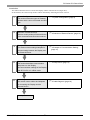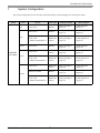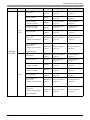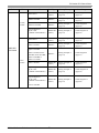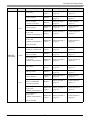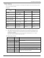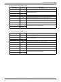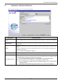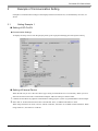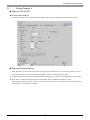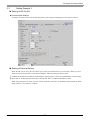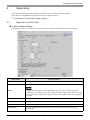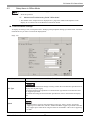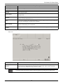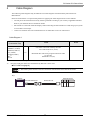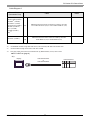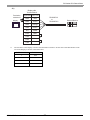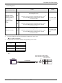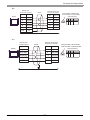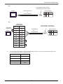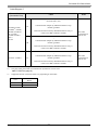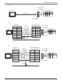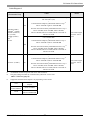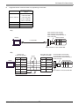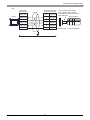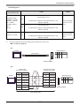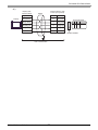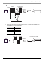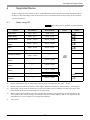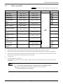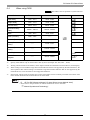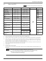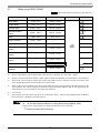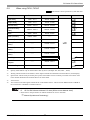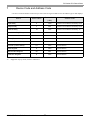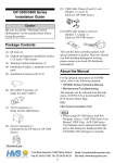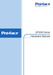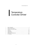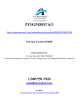
1
Mitsubishi Electric Corporation FX Series CPU Direct Driver 1 System Configuration....................................................................................................... 3 2 Selection of External Device .......................................................................................... 10 3 Example of Communication Setting ............................................................................... 11 4 Setup Items .................................................................................................................... 14 5 Cable Diagram ............................................................................................................... 18 6 Supported Device........................................................................................................... 45 7 Device Code and Address Code.................................................................................... 56 8 Error Messages.............................................................................................................. 57 1 FX Series CPU Direct Driver Introduction This manual describes how to connect the Display and the External Device (target PLC). In this manual, the connection procedure will be described by following the below sections: 1 System Configuration This section shows the types of External Devices which can be connected and SIO type. "1 System Configuration" (page 3) 2 Selection of External Device Select a model (series) of External Device to be connected and connection method. "2 Selection of External Device" (page 10) 3 Example of Communication Settings This section shows setting examples for communicating between the Display and the External Device. "3 Example of Communication Setting" 4 Setup Items This section describes communication setup items on the Display. Set communication settings of the Display with GP-Pro Ex or in offline mode. "4 Setup Items" (page 14) 5 Cable Diagram This section shows cables and adapters for connecting the Display and the External Device. "5 Cable Diagram" (page 18) Operation GP-Pro EX Device/PLC Connection Manual 2 (page 11) FX Series CPU Direct Driver 1 System Configuration The system configuration in the case when the External Device and the Display are connected is shown. Series CPU FX1 FX2 FX2C MELSEC FX Series FX0S Link I/F SIO Type Setting Example Cable Diagram CPU Direct RS232C Setting Example 1 (page 11) Cable Diagram 1 (page 18) CPU Direct RS232C Setting Example 1 (page 11) Cable Diagram 1 (page 18) 2-port adapter II by Pro-face (Model: GP070-MD11) RS422/485 (4wire) Setting Example 3 (page 13) Cable Diagram 10 (page 36) CPU Direct RS232C Setting Example 1 (page 11) Cable Diagram 1 (page 18) CPU Direct RS422/485 (4wire) Setting Example 2 (page 12) Cable Diagram 2 (page 19) RS422/485 (4wire) Setting Example 3 (page 13) Cable Diagram 10 (page 36) CPU Direct RS422/485 (4wire) Setting Example 2 (page 12) Cable Diagram 2 (page 19) FX2NC-232ADP RS232C Setting Example 1 (page 11) Cable Diagram 9 (page 34) 2-port adapter II by Pro-face (Model: GP070-MD11) RS422/485 (4wire) Setting Example 3 (page 13) Cable Diagram 10 (page 36) 2-port adapter II by Pro-face (Model: GP070-MD11) FX0N GP-Pro EX Device/PLC Connection Manual 3 FX Series CPU Direct Driver Series CPU FX1S, FX1N Link I/F FX2N Setting Example Cable Diagram CPU Direct RS422/485 (4wire) Setting Example 2 (page 12) Cable Diagram 2 (page 19) FX1N-232-BD RS232C Setting Example 1 (page 11) Cable Diagram 3 (page 21) FX0N-232ADP + FX1N-CNV-BD RS232C Setting Example 1 (page 11) Cable Diagram 4 (page 23) FX2NC-232ADP + FX1N-CNV-BD RS232C Setting Example 1 (page 11) Cable Diagram 7 (page 29) FX1N-422-BD RS422/485 (4wire) Setting Example 2 (page 12) Cable Diagram 6 (page 27) RS422/485 (4wire) Setting Example 3 (page 13) Cable Diagram 10 (page 36) 2-port adapter II by Pro-face (Model: GP070-MD11) + FX1N-422-BD RS422/485 (4wire) Setting Example 3 (page 13) Cable Diagram 11 (page 40) CPU Direct RS422/485 (4wire) Setting Example 2 (page 12) Cable Diagram 2 (page 19) FX2N-232-BD RS232C Setting Example 1 (page 11) Cable Diagram 3 (page 21) FX0N-232ADP + FX2N-CNV-BD RS232C Setting Example 1 (page 11) Cable Diagram 4 (page 23) FX2NC-232ADP +FX2N-CNV-BD RS232C Setting Example 1 (page 11) Cable Diagram 7 (page 29) FX2N-422-BD RS422/485 (4wire) Setting Example 2 (page 12) Cable Diagram 6 (page 27) RS422/485 (4wire) Setting Example 3 (page 13) Cable Diagram 10 (page 36) RS422/485 (4wire) Setting Example 3 (page 13) Cable Diagram 11 (page 40) 2-port adapter II by Pro-face (Model: GP070-MD11) MELSEC FX Series SIO Type 2-port adapter II by Pro-face (Model: GP070-MD11) 2-port adapter II by Pro-face (Model: GP070-MD11) + FX2N-422-BD GP-Pro EX Device/PLC Connection Manual 4 FX Series CPU Direct Driver Series CPU FX1NC, FX2NC MELSEC FX Series FX3U, FX3UC Link I/F SIO Type Setting Example Cable Diagram CPU Direct RS422/485 (4wire) Setting Example 2 (page 12) Cable Diagram 2 (page 19) FX0N-232ADP RS232C Setting Example 1 (page 11) Cable Diagram 5 (page 25) FX2NC-232ADP RS232C Setting Example 1 (page 11) Cable Diagram 9 (page 34) 2-port adapter II by Pro-face (Model: GP070-MD11) RS422/485 (4wire) Setting Example 3 (page 13) Cable Diagram 10 (page 36) CPU Direct RS422/485 (4wire) Setting Example 2 (page 12) Cable Diagram 2 (page 19) FX3U-232-BD RS232C Setting Example 1 (page 11) Cable Diagram 3 (page 21) FX3U-232ADP + FX3U-232-BD, FX3U422-BD, FX3U-485-BD, FX3U-USB-BD or FX3U-CNV-BD RS232C Setting Example 1 (page 11) Cable Diagram 8 (page 31) FX3U-422-BD RS422/485 (4wire) Setting Example 2 (page 12) Cable Diagram 6 (page 27) RS422/485 (4wire) Setting Example 3 (page 13) Cable Diagram 10 (page 36) RS422/485 (4wire) Setting Example 3 (page 13) Cable Diagram 11 (page 40) 2-port adapter II by Pro-face (Model: GP070-MD11) 2-port adapter II by Pro-face (Model: GP070-MD11) + FX3U-422-BD GP-Pro EX Device/PLC Connection Manual 5 FX Series CPU Direct Driver Series CPU FX3G MELSEC FX Series FX3GC Link I/F Setting Example Cable Diagram CPU Direct RS422/485 (4wire) Setting Example 2 (page 12) Cable Diagram 2 (page 19) FX3G-232-BD RS232C Setting Example 1 (page 11) Cable Diagram 3 (page 21) FX3U-232ADP + FX3G-CNV-ADP RS232C Setting Example 1 (page 11) Cable Diagram 8 (page 31) FX3G-422-BD RS422/485 (4wire) Setting Example 2 (page 12) Cable Diagram 6 (page 27) 2-port adapter II by Pro-face (Model: GP070-MD11) RS422/485 (4wire) Setting Example 3 (page 13) Cable Diagram 10 (page 36) 2-port adapter II by Pro-face (Model: GP070-MD11) + FX3G-422-BD RS422/485 (4wire) Setting Example 3 (page 13) Cable Diagram 11 (page 40) Peripheral device connector on Main Unit RS422/485 (4wire) Setting Example 2 (page 12) Cable Diagram 2 (page 19) RS-232C Connector on FX3U-232ADP RS232C Setting Example 1 (page 11) Cable Diagram 8 (page 31) RS422/485 (4wire) Setting Example 3 (page 13) Cable Diagram 10 (page 36) CPU Direct RS422/485 (4wire) Setting Example 2 (page 12) Cable Diagram 2 (page 19) FX3G-232-BD RS232C Setting Example 1 (page 11) Cable Diagram 3 (page 21) FX3G-422-BD RS422/485 (4wire) Setting Example 2 (page 12) Cable Diagram 6 (page 27) FX3U-232ADP or FX3U-232ADP-MB + FX3S-CNV-ADP RS232C Setting Example 1 (page 11) Cable Diagram 8 (page 31) 2-port adapter II by Pro-face (Model: GP070-MD11) RS422/485 (4wire) Setting Example 3 (page 13) Cable Diagram 10 (page 36) 2-port adapter II by Pro-face (Model: GP070-MD11) + FX3G-422-BD RS422/485 (4wire) Setting Example 3 (page 13) Cable Diagram 11 (page 40) 2-port adapter II by Pro-face (Model: GP070-MD11) FX3S SIO Type GP-Pro EX Device/PLC Connection Manual 6 FX Series CPU Direct Driver • When the time of GP4000 series is automatically updated in [Clock Update Settings] of GP-Pro EX, there are some restrictions as shown below. For details on [Clock Update Settings], refer to GP-Pro EX Reference Manual. • FX0S, FX0N and FX1 does not support automatic update of the time. Specify [Customize] in [Clock Update Settings]. • When the time is automatically updated in FX2, FX2C and FX2NC, the real time clock function board or the E2PROM memory with the real time clock function is required. GP-Pro EX Device/PLC Connection Manual 7 FX Series CPU Direct Driver IPC COM Port When connecting IPC with an External Device, the COM port used depends on the series and SIO type. Please refer to the IPC manual for details. Usable port Usable Port Series RS-232C RS-422/485(4 wire) RS-422/485(2 wire) *1 PS-2000B COM1 , COM2, COM3*1, COM4 - - PS-3450A, PS-3451A, PS3000-BA, PS3001-BD COM1, COM2*1*2 COM2*1*2 COM2*1*2 PS-3650A (T41 model), PS-3651A (T41 model) COM1*1 - - PS-3650A (T42 model), PS-3651A (T42 model) COM1*1*2, COM2 COM1*1*2 COM1*1*2 PS-3700A (Pentium®4-M) PS-3710A COM1*1, COM2*1, COM3*2 , COM4 COM3*2 COM3*2 PS-3711A COM1*1, COM2*2 COM2*2 COM2*2 PS4000*3 COM1, COM2 - - COM1*1*2 COM1*1*2 COM1*1*2, PL3000 COM2*1, COM3, COM4 *1 The RI/5V can be switched. Use the IPC’s switch to change if necessary. *2 Set up the SIO type with the DIP Switch. Please set up as follows according to SIO type to be used. *3 When making communication between an External Device and COM port on the Expansion slot, only RS-232C is supported. However, ER (DTR/CTS) control cannot be executed because of the specification of COM port. For connection with External Device, use user-created cables and disable Pin Nos. 1, 4, 6 and 9. Please refer to the IPC manual for details of pin layout. DIP Switch setting: RS-232C DIP Switch Setting 1 OFF*1 Description 2 OFF 3 OFF 4 OFF Output mode of SD (TXD) data: Always output 5 OFF Terminal resistance (220) insertion to SD (TXD): None 6 OFF Terminal resistance (220) insertion to RD (RXD): None 7 OFF Short-circuit of SDA (TXA) and RDA (RXA): Not available 8 OFF Short-circuit of SDB (TXB) and RDB (RXB): Not available 9 OFF 10 OFF Reserved (always OFF) SIO type: RS-232C RS (RTS) Auto control mode: Disabled *1 When using PS-3450A, PS-3451A, PS3000-BA and PS3001-BD, turn ON the set value. GP-Pro EX Device/PLC Connection Manual 8 FX Series CPU Direct Driver DIP Switch setting: RS-422/485 (4 wire) DIP Switch Setting Description 1 OFF 2 ON 3 ON 4 OFF Output mode of SD (TXD) data: Always output 5 OFF Terminal resistance (220) insertion to SD (TXD): None 6 OFF Terminal resistance (220) insertion to RD (RXD): None 7 OFF Short-circuit of SDA (TXA) and RDA (RXA): Not available 8 OFF Short-circuit of SDB (TXB) and RDB (RXB): Not available 9 OFF 10 OFF Reserved (always OFF) SIO type: RS-422/485 RS (RTS) Auto control mode: Disabled DIP Switch setting: RS-422/485 (2 wire) DIP Switch Setting Description 1 OFF 2 ON 3 ON 4 OFF Output mode of SD (TXD) data: Always output 5 OFF Terminal resistance (220) insertion to SD (TXD): None 6 OFF Terminal resistance (220) insertion to RD (RXD): None 7 ON Short-circuit of SDA (TXA) and RDA (RXA): Available 8 ON Short-circuit of SDB (TXB) and RDB (RXB): Available 9 ON 10 ON Reserved (always OFF) SIO type: RS-422/485 RS (RTS) Auto control mode: Enabled GP-Pro EX Device/PLC Connection Manual 9 FX Series CPU Direct Driver 2 Selection of External Device Select the External Device to be connected to the Display. Setup Items Setup Description Number of Devices/ PLCs Enter an integer from 1 to 4 to define the number of Devices/PLCs to connect to the display. Manufacturer Select the manufacturer of the External Device to connect. Select "Mitsubishi Electric Corporation". Series Select the External Device model (series) and the connection method. Select "FX Series CPU Direct". In System configuration, make sure the External Device you are connecting is supported by "FX Series CPU Direct". "1 System Configuration" (page 3) Port Select the Display port to connect to the External Device. Use System Area Check this option to synchronize the system data area of the Display and the device (memory) of the External Device. When synchronized, you can use the External Device’s ladder program to switch the display or display the window on the Display. Cf. GP-Pro EX Reference Manual "LS Area (Direct Access Method Area)" This feature can also be set in GP-Pro EX or in the Display's offline mode. Cf. GP-Pro EX Reference Manual "System Settings [Display Unit] - [System Area] Settings Guide" Cf. Maintenance/Troubleshooting Guide "Main Unit - System Area Settings" GP-Pro EX Device/PLC Connection Manual 10 FX Series CPU Direct Driver 3 Example of Communication Setting Examples of communication settings of the Display and the External Device, recommended by Pro-face, are shown. 3.1 Setting Example 1 Setting of GP-Pro EX Communication Settings To display the setup screen, from the [Project] menu, point to [System Settings] and select [Device/PLC]. Setting of External Device When the link I/F you use is the CPU Direct type, setting of External Device is not necessary. When you use a function extension board and a communication adapter, make the settings as shown below. 1 2 Uncheck the checkbox for [Operate communication setting] in [PLC system (2)] of Mitsubishi's GP-Developer. Store data "0" in D8120 and between D8173 and D8180. Then, set M8070 and M8071 to OFF. When using Channel 2 for FX3U, FX3UC, FX3G or FX3GC, store data "0" in D8420 instead of D8120. When using Channel 1, store data "0" in D8120. GP-Pro EX Device/PLC Connection Manual 11 FX Series CPU Direct Driver 3.2 Setting Example 2 Setting of GP-Pro EX Communication Settings To display the setup screen, from the [Project] menu, point to [System Settings] and select [Device/PLC]. Setting of External Device When the link I/F you use is the CPU Direct type, setting of External Device is not necessary. When you use a function extension board and a communication adapter, make the settings as shown below. 1 2 Uncheck the checkbox for [Operate communication setting] in [PLC system (2)] of Mitsubishi's GP-Developer. Store data "0" in D8120 and between D8173 and D8180. Then, set M8070 and M8071 to OFF. When using Channel 2 for FX3U, FX3UC, FX3G or FX3GC, store data "0" in D8420 instead of D8120. When using Channel 1, store data "0" in D8120. GP-Pro EX Device/PLC Connection Manual 12 FX Series CPU Direct Driver 3.3 Setting Example 3 Setting of GP-Pro EX Communication Settings To display the setup screen, from the [Project] menu, point to [System Settings] and select [Device/PLC]. Setting of External Device When the link I/F you use is the CPU Direct type, setting of External Device is not necessary. When you use a function extension board and a communication adapter, make the settings as shown below. 1 2 Uncheck the checkbox for [Operate communication setting] in [PLC system (2)] of Mitsubishi's GP-Developer. Store data "0" in D8120 and between D8173 and D8180. Then, set M8070 and M8071 to OFF. When using Channel 2 for FX3U, FX3UC, FX3G or FX3GC, store data "0" in D8420 instead of D8120. When using Channel 1, store data "0" in D8120. GP-Pro EX Device/PLC Connection Manual 13 FX Series CPU Direct Driver 4 Setup Items Set communication settings of the Display with GP-Pro EX or in offline mode of the Display. The setting of each parameter must be identical to that of External Device. "3 Example of Communication Setting" (page 11) 4.1 Setup Items in GP-Pro EX Communication Settings To display the setup screen, from the [Project] menu, point to [System Settings] and select [Device/PLC]. Setup Items SIO Type Setup Description Select the SIO type to communicate with the External Device. Select speed between External Device and Display. Speed • Supported range of speed varies depending on the type. FX3U, FX3UC and FX3G support up to 115.2K. FX1N, FX1NC, FX2N and FX2NC support up to 38400. Note that they support up to 19200 when using FX-232W or FX232AWC. Other CPUs support up to 9600. Data Length Select data length. Parity Select how to check parity. Stop Bit Select stop bit length. Flow Control Select the communication control method to prevent overflow of transmission and reception data. GP-Pro EX Device/PLC Connection Manual 14 FX Series CPU Direct Driver Setup Items Setup Description Timeout Use an integer from 1 to 127 to enter the time (s) for which the Display waits for the response from the External Device. Retry In case of no response from the External Device, use an integer from 0 to 255 to enter how many times the Display retransmits the command. Wait To Send Use an integer from 0 to 255 to enter standby time (ms) for the Display from receiving packets to transmitting next commands. Adapter Select "Direct" or "2 Port " for the adapter to be used. When using 2-port adapter II, select "2 Port". RI/VCC You can switch RI/VCC of the 9th pin when you select RS232C for SIO type. It is necessary to change RI/5V by changeover switch of IPC when connect with IPC. Please refer to the manual of the IPC for more detail. • Refer to the GP-Pro EX Reference Manual for Indirect Device. Cf. GP-Pro EX Reference Manual "Changing the Device/PLC at Runtime (Indirect Device)" GP-Pro EX Device/PLC Connection Manual 15 FX Series CPU Direct Driver 4.2 Setup Items in Offline Mode • Refer to the Maintenance/Troubleshooting guide for information on how to enter offline mode or about the operation. Cf. Maintenance/Troubleshooting Guide "Offline Mode" • The number of the setup items to be displayed for 1 page in the offline mode depends on the Display in use. Please refer to the Reference manual for details. Communication Settings To display the setting screen, touch [Device/PLC Settings] from [Peripheral Settings] in offline mode. Touch the External Device you want to set from the displayed list. (Page 1/2) Setup Items Setup Description Select the SIO type to communicate with the External Device. SIO Type To make the communication settings correctly, confirm the serial interface specifications of Display unit for [SIO Type]. We cannot guarantee the operation if a communication type that the serial interface does not support is specified. For details concerning the serial interface specifications, refer to the manual for Display unit. Select speed between External Device and Display. Speed • Supported range of speed varies depending on the type. FX3U, FX3UC and FX3G support up to 115.2K. FX1N, FX1NC, FX2N and FX2NC support up to 38400. Note that they support up to 19200 when using FX-232W or FX232AWC. Other CPUs support up to 9600. GP-Pro EX Device/PLC Connection Manual 16 FX Series CPU Direct Driver Setup Items Setup Description Data Length Select data length. Parity Select how to check parity. Stop Bit Select stop bit length. Flow Control Select the communication control method to prevent overflow of transmission and reception data. Timeout Use an integer from 1 to 127 to enter the time (s) for which the Display waits for the response from the External Device. Retry In case of no response from the External Device, use an integer from 0 to 255 to enter how many times the Display retransmits the command. Wait To Send Use an integer from 0 to 255 to enter standby time (ms) for the Display from receiving packets to transmitting next commands. Adapter Select "Direct" or "2 Port " for the adapter to be used. When using 2-port adapter II, select "2 Port". (Page 2/2) Setup Items RI/VCC Setup Description You can switch RI/VCC of the 9th pin when you select RS232C for SIO type. It is necessary to change RI/5V by changeover switch of IPC when connect with IPC. Please refer to the manual of the IPC for more detail. • GP-4100 series and GP-4*01TM do not have the [RI/VCC] setting in the offline mode. GP-Pro EX Device/PLC Connection Manual 17 FX Series CPU Direct Driver 5 Cable Diagram The following cable diagrams may be different from cable diagrams recommended by External Device Manufacturer. Please be assured there is no operational problem in applying the cable diagram shown in this manual. • The FG pin of the External Device body must be grounded according to your country’s applicable standard. Refer to your External Device manual for details. • SG and FG are connected inside the Display. When connecting the External Device to SG, design your system to avoid short-circuit loops. • Connect an isolation unit if the communication is not stable due to noise or other factors. Cable Diagram 1 External Device (Connection Port) GP3000 (COM1) GP4000*1 (COM1) SP5000 (COM1/2) ST (COM1) LT3000 (COM1) IPC*2 PC/AT Cable 1A Notes 9-25 232C conversion cable by Pro-face CA3-CBLCBT232-01 (0.2m) + Mitsubishi PLC FX Series program control I/F cable by Pro-face GP430-IP11-O (5m) *1 All GP4000 models except GP-4100 series, GP-4*01TM, and GP-4203T *2 Only the COM port which can communicate by RS-232C can be used. IPC COM Port (page 8) • This cable system cannot be used for connection with GP-4100 series and GP-4*01TM. 1A) Display External Device CA3-CBLCBT232-01 GP-Pro EX Device/PLC Connection Manual GP430-IP11-O 18 FX Series CPU Direct Driver Cable Diagram 2 External Device (Connection Port) GP3000*1 (COM1) AGP-3302B (COM2) GP4000*2 (COM2) GP-4201T (COM1) GP-4*01TM (COM1) SP5000 (COM1/2) ST*3 (COM2) LT3000 (COM1) IPC*4 GP-4106 (COM1) Cable Notes 2A Mitsubishi PLC FX-Series Connection Cable by Pro-face CA3-CBLFX/1M-01 (1m) or CA3-CBLFX/5M-01 (5m) 2B Mitsubishi PLC FX Series CPU I/F Cable by Pro-face ZC9CBFX11 (1m) or ZC9CBFX51 (5m) *1 All GP3000 models except AGP-3302B *2 All GP4000 models except GP-4100 series, GP-4*01TM, GP-4201T and GP-4*03T *3 All ST models except AST-3211A and AST-3302B *4 Only the COM port which can communicate by RS-422/485 (4 wire) can be used. IPC COM Port (page 8) 2A) Display GP-Pro EX Device/PLC Connection Manual CA3-CBLFX/1M-01 or CA3-CBLFX/5M-01 19 External Device FX Series CPU Direct Driver 2B) Display side Terminal block Signal name Cable color Termination resistance*1 Display *1 RDA Red RDB Green SDA Orange SDB Brown SG Yellow ERA Blue CSA Blue ERB Blue CSB Blue ZC9CBFX11 or ZC9CBFX51 External Device The resistance in the Display is used as the termination resistance. Set the value of the DIP Switch on the rear of the Display as shown in the table below. DIP Switch No. Set Value 1 OFF 2 OFF 3 ON 4 OFF GP-Pro EX Device/PLC Connection Manual 20 FX Series CPU Direct Driver Cable Diagram 3 External Device (Connection Port) GP3000 (COM1) GP4000*1 (COM1) SP5000 (COM1/2) ST (COM1) LT3000 (COM1) IPC*2 PC/AT GP-4105 (COM1) Cable 3A Notes RS232C communication cable by Mitsubishi Electric Corp. FX-232CAB-1 (3m) + Function extension board by Mitsubishi Electric Corp.*3 FX1N-232-BD, FX2N-232-BD, FX3U-232-BD or FX3G-232-BD 3B User-created cable + Function extension board by Mitsubishi Electric Corp.*3 FX1N-232-BD, FX2N-232-BD, FX3U-232-BD or FX3G-232-BD 3C User-created cable + Function extension board by Mitsubishi Electric Corp.*3 FX1N-232-BD, FX2N-232-BD, FX3U-232-BD or FX3G-232-BD *1 All GP4000 models except GP-4100 series and GP-4203T *2 Only the COM port which can communicate by RS-232C can be used. IPC COM Port (page 8) *3 Supported function extension boards vary depending on the model. CPU FX1S, FX1N FX2N FX3U, FX3UC FX3G, FX3S The cable length must be 15m or less. The cable length must be 15m or less. Function Extension Board FX1N-232-BD FX2N-232-BD FX3U-232-BD FX3G-232-BD 3A) FX1N-232-BD, FX2N-232-BD, FX3U-232-BD or FX3G-232-BD External Device Display FX-232CAB-1 GP-Pro EX Device/PLC Connection Manual 21 FX Series CPU Direct Driver 3B) Display side D-sub 9 pin (socket) Display External Device side D-sub 9 pin (socket) Shield Pin Signal name Pin Signal name 2 RD(RXD) 2 RD(RXD) 3 SD(TXD) 3 SD(TXD) 4 ER(DTR) 4 ER(DTR) 8 CS(CTS) 6 DR(DSR) 5 SG 5 SG Shell FG FX1N-232-BD, FX2N-232-BD, FX3U-232-BD or FX3G-232-BD External Device User-created cable 3C) Display side Terminal block Display External Device side D-sub 9 pin (socket) Shield Signal name Pin Signal name RD(RXD) 2 RD(RXD) SD(TXD) 3 SD(TXD) ER(DTR) 4 ER(DTR) 6 DR(DSR) 5 SG CS(CTS) SG User-created cable GP-Pro EX Device/PLC Connection Manual 22 FX1N-232-BD, FX2N-232-BD, FX3U-232-BD or FX3G-232-BD External Device FX Series CPU Direct Driver Cable Diagram 4 External Device Cable 4A GP3000 (COM1) GP4000*1 (COM1) SP5000 (COM1/2) ST (COM1) LT3000 (COM1) IPC*2 PC/AT GP-4105 (COM1) RS-232C cable by Pro-face CA3-CBL232/5M-01 (5m) + Communication adapter by Mitsubishi Electric Corp. FX0N-232ADP + Function extension board by Mitsubishi Electric Corp.*3 FX1N-CNV-BD or FX2N-CNV-BD 4B User-created cable + Communication adapter by Mitsubishi Electric Corp. FX0N-232ADP + Function extension board by Mitsubishi Electric Corp.*3 FX1N-CNV-BD or FX2N-CNV-BD 4C User-created cable + Communication adapter by Mitsubishi Electric Corp. FX0N-232ADP + Function extension board by Mitsubishi Electric Corp.*3 FX1N-CNV-BD or FX2N-CNV-BD *1 All GP4000 models except GP-4100 series and GP-4203T *2 Only the COM port which can communicate by RS-232C can be used. IPC COM Port (page 8) *3 Supported function extension boards vary depending on the model. CPU FX1S, FX1N FX2N Function Extension Board FX1N-CNV-BD FX2N-CNV-BD GP-Pro EX Device/PLC Connection Manual 23 Notes The cable length must be 15m or less. The cable length must be 15m or less. FX Series CPU Direct Driver 4A) FX1N-CNV-BD or FX2N-CNV-BD Display External Device CA3-CBL232/5M-01 FX0N-232ADP 4B) Display side D-sub 9 pin (socket) Display External Device side D-sub 25 pin (plug) Shield Pin Signal name Pin Signal name 2 RD(RXD) 2 SD(TXD) 3 SD(TXD) 3 RD(RXD) 4 ER(DTR) 6 DR(DSR) 8 CS(CTS) 7 SG 5 SG 20 ER(DTR) Shell FG FX1N-CNV-BD or FX2N-CNV-BD External Device FX0N-232ADP User-created cable 4C) Display side Terminal block Display Shield External Device side D-sub 25 pin (plug) Signal name Pin Signal name RD(RXD) 2 SD(TXD) SD(TXD) 3 RD(RXD) ER(DTR) 6 DR(DSR) CS(CTS) 7 SG SG 20 ER(DTR) FX1N-CNV-BD or FX2N-CNV-BD External Device FX0N-232ADP User-created cable GP-Pro EX Device/PLC Connection Manual 24 FX Series CPU Direct Driver Cable Diagram 5 External Device (Connection Port) GP3000 (COM1) GP4000*1 (COM1) SP5000 (COM1/2) ST (COM1) LT3000 (COM1) IPC*2 PC/AT GP-4105 (COM1) Cable 5A Notes RS-232C cable by Pro-face CA3-CBL232/5M-01 (5m) + Communication adapter by Mitsubishi Electric Corp. FX0N-232ADP 5B User-created cable + Communication adapter by Mitsubishi Electric Corp. FX0N-232ADP 5C User-created cable + Communication adapter by Mitsubishi Electric Corp. FX0N-232ADP *1 All GP4000 models except GP-4100 series and GP-4203T *2 Only the COM port which can communicate by RS-232C can be used. IPC COM Port (page 8) The cable length must be 15m or less. The cable length must be 15m or less. 5A) Display External Device CA3-CBL232/5M-01 FX0N-232ADP GP-Pro EX Device/PLC Connection Manual 25 FX Series CPU Direct Driver 5B) Display side D-sub 9 pin (socket) Display External Device side D-sub 25 pin (plug) Shield Pin Signal name Pin Signal name 2 RD(RXD) 2 SD(TXD) 3 SD(TXD) 3 RD(RXD) 4 ER(DTR) 6 DR(DSR) 8 CS(CTS) 7 SG 5 SG 20 ER(DTR) Shell FG External Device FX0N-232ADP User-created cable 5C) Display side Terminal block Display Shield External Device side D-sub 25 pin (plug) Signal name Pin Signal name RD(RXD) 2 SD(TXD) SD(TXD) 3 RD(RXD) ER(DTR) 6 DR(DSR) CS(CTS) 7 SG SG 20 ER(DTR) External Device FX0N-232ADP User-created cable GP-Pro EX Device/PLC Connection Manual 26 FX Series CPU Direct Driver Cable Diagram 6 External Device (Connection Port) GP3000*1 (COM1) AGP-3302B (COM2) GP4000*2 (COM2) GP-4201T (COM1) GP-4*01TM (COM1) SP5000 (COM1/2) ST*3 (COM2) LT3000 (COM1) IPC*4 GP-4106 (COM1) Cable 6A Mitsubishi FX connection cable by Pro-face CA3-CBLFX/1M-01 (1m) or CA3-CBLFX/5M-01 (5m) + Function extension board by Mitsubishi Electric Corp.*5 FX1N-422-BD, FX2N-422-BD, FX3U-422-BD or FX3G-422-BD 6B Mitsubishi PLC FX Series CPU I/F Cable by Pro-face ZC9CBFX11 (1m) or ZC9CBFX51 (5m) + Function extension board by Mitsubishi Electric Corp.*5 FX1N-422-BD, FX2N-422-BD, FX3U-422-BD or FX3G-422-BD *1 All GP3000 models except AGP-3302B *2 All GP4000 models except GP-4100 series, GP-4*01TM, GP-4201T and GP-4*03T *3 All ST models except AST-3211A and AST-3302B *4 Only the COM port which can communicate by RS-422/485 (4 wire) can be used. IPC COM Port (page 8) *5 Supported function extension boards vary depending on the model. CPU FX1S, FX1N FX2N FX3U, FX3UC FX3G, FX3S Function Extension Board FX1N-422-BD FX2N-422-BD FX3U-422-BD FX3G-422-BD GP-Pro EX Device/PLC Connection Manual 27 Notes FX Series CPU Direct Driver 6A) FX1N-422-BD, FX2N-422-BD, FX3U-422-BD or FX3G-422-BD Display CA3-CBLFX/1M-01 or CA3-CBLFX/5M-01 External Device 6B) Display side Terminal block Termination resistance*1 Display *1 FX1N-422-BD, FX2N-422-BD, FX3U-422-BD or FX3G-422-BD Signal name Cable color RDA Red RDB Green SDA Orange SDB Brown SG Yellow ERA Blue CSA Blue ERB Blue CSB Blue ZC9CBFX11 or ZC9CBFX51 External Device The resistance in the Display is used as the termination resistance. Set the value of the DIP Switch on the rear of the Display as shown in the table below. DIP Switch No. Set Value 1 OFF 2 OFF 3 ON 4 OFF GP-Pro EX Device/PLC Connection Manual 28 FX Series CPU Direct Driver Cable Diagram 7 External Device (Connection Port) Cable 7A GP3000 (COM1) GP4000*1 (COM1) SP5000 (COM1/2) ST (COM1) LT3000 (COM1) IPC*2 PC/AT GP-4105 (COM1) RS232C communication cable by Mitsubishi Electric Corp. FX-232CAB-1 (3m) + Communication adapter by Mitsubishi Electric Corp. FX2NC-232ADP + Function extension board by Mitsubishi Electric Corp.*3 FX1N-CNV-BD or FX2N-CNV-BD 7B User-created cable + Communication adapter by Mitsubishi Electric Corp. FX2NC-232ADP + Function extension board by Mitsubishi Electric Corp.*3 FX1N-CNV-BD or FX2N-CNV-BD 7C User-created cable + Communication adapter by Mitsubishi Electric Corp. FX2NC-232ADP + Function extension board by Mitsubishi Electric Corp.*3 FX1N-CNV-BD or FX2N-CNV-BD *1 All GP4000 models except GP-4100 series and GP-4203T *2 Only the COM port which can communicate by RS-232C can be used. IPC COM Port (page 8) *3 Supported function extension boards vary depending on the model. CPU FX1S, FX1N FX2N Function Extension Board FX1N-CNV-BD FX2N-CNV-BD GP-Pro EX Device/PLC Connection Manual 29 Notes The cable length must be 15m or less. The cable length must be 15m or less. FX Series CPU Direct Driver 7A) FX1N-CNV-BD or FX2N-CNV-BD Display External Device FX-232CAB-1 FX2NC-232ADP 7B) Display side D-sub 9 pin (socket) Display External Device side D-sub 9 pin (socket) Shield Pin Signal name Pin Signal name 2 RD(RXD) 2 RD(RXD) 3 SD(TXD) 3 SD(TXD) 4 ER(DTR) 4 ER(DTR) 8 CS(CTS) 6 DR(DSR) 5 SG 5 SG Shell FG FX1N-CNV-BD or FX2N-CNV-BD External Device FX2NC-232ADP User-created cable 7C) Display side Terminal block Display Shield External Device side D-sub 9 pin (socket) Signal name Pin Signal name RD(RXD) 2 RD(RXD) SD(TXD) 3 SD(TXD) ER( DTR ) 4 ER(DTR) CS(CTS) 6 DR(DSR) SG 5 SG User-created cable GP-Pro EX Device/PLC Connection Manual 30 FX1N-CNV-BD or FX2N-CNV-BD External Device FX2NC-232ADP FX Series CPU Direct Driver Cable Diagram 8 External Device (Connection Port) Cable 8A GP3000 (COM1) GP4000*1 (COM1) SP5000 (COM1/2) ST (COM1) LT3000 (COM1) IPC*2 PC/AT GP-4105 (COM1) RS232C communication cable by Mitsubishi Electric Corp. FX-232CAB-1 (3m) + Communication adapter by Mitsubishi Electric Corp.*3 FX3U-232ADP or FX3U-232ADP-MB + Function extension board by Mitsubishi Electric Corp.*4 FX3U-232-BD, FX3U-422-BD, FX3U-485-BD, FX3U-USB-BD, FX3U-CNV-BD, FX3G-CNV-ADP or FX3S-CNV-ADP 8B User-created cable + Communication adapter by Mitsubishi Electric Corp.*3 FX3U-232ADP or FX3U-232ADP-MB + Function extension board by Mitsubishi Electric Corp.*4 FX3U-232-BD, FX3U-422-BD, FX3U-485-BD, FX3U-USB-BD, FX3U-CNV-BD, FX3G-CNV-ADP or FX3S-CNV-ADP 8C User-created cable + Communication adapter by Mitsubishi Electric Corp.*3 FX3U-232ADP or FX3U-232ADP-MB + Function extension board by Mitsubishi Electric Corp.*4 FX3U-232-BD, FX3U-422-BD, FX3U-485-BD, FX3U-USB-BD, FX3U-CNV-BD, FX3G-CNV-ADP or FX3S-CNV-ADP *1 All GP4000 models except GP-4100 series and GP-4203T *2 Only the COM port which can communicate by RS-232C can be used. IPC COM Port (page 8) *3 Supported communication adapters vary depending on the model. CPU Communication Adapter FX3U, FX3UC, FX3G, FX3GC FX3U-232ADP FX3S FX3U-232ADP or FX3U-232ADP-MB GP-Pro EX Device/PLC Connection Manual 31 Notes The cable length must be 15m or less. The cable length must be 15m or less. FX Series CPU Direct Driver *4 Supported function extension boards vary depending on the model. CPU FX3U, FX3UC FX3G FX3GC FX3S Function Extension Board FX3U-232-BD FX3U-422-BD FX3U-485-BD FX3U-USB-BD FX3U-CNV-BD FX3G-CNV-ADP FX3S-CNV-ADP 8A) FX3U-232-BD, FX3U-422-BD, FX3U-485-BD, FX3U-USB-BD, FX3U-CNV-BD, FX3G-CNV-ADP or FX3S-CNV-ADP External Device Display FX-232CAB-1 FX3U-232ADP or FX3U-232ADP-MB 8B) Display side D-sub 9 pin (socket) Display External Device side D-sub 9 pin (socket) Shield Pin Signal name Pin Signal name 2 RD(RXD) 2 RD(RXD) 3 SD(TXD) 3 SD(TXD) 4 ER(DTR) 4 ER(DTR) 8 CS(CTS) 6 DR(DSR) 5 SG 5 SG Shell FG User-created cable GP-Pro EX Device/PLC Connection Manual 32 FX3U-232-BD, FX3U-422-BD, FX3U-485-BD, FX3U-USB-BD, FX3U-CNV-BD, FX3G-CNV-ADP or FX3S-CNV-ADP External Device FX3U-232ADP or FX3U-232ADP-MB FX Series CPU Direct Driver 8C) Display side Terminal block Display Shield External Device side D-sub 9 pin (socket) Signal name Pin Signal name RD(RXD) 2 RD(RXD) SD(TXD) 3 SD(TXD) ER(DTR) 4 ER(DTR) CS(CTS) 6 DR(DSR) SG 5 SG User-created cable GP-Pro EX Device/PLC Connection Manual 33 FX3U-232-BD, FX3U-422-BD, FX3U-485-BD, FX3U-USB-BD, FX3U-CNV-BD, FX3G-CNV-ADP or FX3S-CNV-ADP External Device FX3U-232ADP or FX3U-232ADP-MB FX Series CPU Direct Driver Cable Diagram 9 External Device (Connection Port) GP3000 (COM1) GP4000*1 (COM1) SP5000 (COM1/2) ST (COM1) LT3000 (COM1) IPC*2 PC/AT Cable RS232C communication cable by Mitsubishi Electric Corp. FX-232CAB-1 (3m) + Communication adapter by Mitsubishi Electric Corp. FX2NC-232ADP 9A GP-4105 (COM1) Notes 9B User-created cable + Communication adapter by Mitsubishi Electric Corp. FX2NC-232ADP 9C User-created cable + Communication adapter by Mitsubishi Electric Corp. FX2NC-232ADP *1 All GP4000 models except GP-4100 series and GP-4203T *2 Only the COM port which can communicate by RS-232C can be used. IPC COM Port (page 8) The cable length must be 15m or less. The cable length must be 15m or less. 9A) Display External Device FX-232CAB-1 FX2NC-232ADP 9B) Display side D-sub 9 pin (socket) Display External Device side D-sub 9 pin (socket) Shield Pin Signal name Pin Signal name 2 RD(RXD) 2 RD(RXD) 3 SD(TXD) 3 SD(TXD) 4 ER(DTR) 4 ER(DTR) 8 CS(CTS) 6 DR(DSR) 5 SG 5 SG Shell FG External Device FX2NC-232ADP User-created cable GP-Pro EX Device/PLC Connection Manual 34 FX Series CPU Direct Driver 9C) Display side Terminal block Display External Device side D-sub 9 pin (socket) Shield Signal name Pin Signal name RD(RXD) 2 RD(RXD) SD(TXD) 3 SD(TXD) ER(DTR) 4 ER(DTR) CS(CTS) 6 DR(DSR) SG 5 SG External Device FX2NC-232ADP User-created cable GP-Pro EX Device/PLC Connection Manual 35 FX Series CPU Direct Driver Cable Diagram 10 External Device (Connection Port) GP3000*1 (COM1) AGP-3302B (COM2) GP-4*01TM (COM1) ST*2 (COM2) LT3000 (COM1) IPC*3 Cable 10A 10B User-created cable + 2-port adapter II by Pro-face GP070-MD11 + Connector conversion cable by Mitsubishi Electric Corp.*4 FX-20P-CADP (0.3m) 10C Online adapter by Pro-face CA4-ADPONL-01 + 2-port adapter cable for AGP by Pro-face CA3-MDCB11 (5m) + 2-port adapter II by Pro-face GP070-MD11 + Connector conversion cable by Mitsubishi Electric Corp.*4 FX-20P-CADP (0.3m) GP3000*5 (COM2) GP-4106 (COM1) COM port conversion adapter by Pro-face CA3-ADPCOM-01 + 2-port adapter cable for AGP by Pro-face CA3-MDCB11 (5m) + 2-port adapter II by Pro-face GP070-MD11 + Connector conversion cable by Mitsubishi Electric Corp.*4 FX-20P-CADP (0.3m) 10D Online adapter by Pro-face CA4-ADPONL-01 + User-created cable + 2-port adapter II by Pro-face GP070-MD11 + Connector conversion cable by Mitsubishi Electric Corp.*4 FX-20P-CADP (0.3m) 10E User-created cable + 2-port adapter II by Pro-face GP070-MD11 + Connector conversion cable by Mitsubishi Electric Corp.*4 FX-20P-CADP (0.3m) GP-Pro EX Device/PLC Connection Manual 36 Notes The cable length must be 600m or less. The cable length must be 600m or less. The cable length must be 600m or less. FX Series CPU Direct Driver External Device (Connection Port) Cable 10F GP4000*6 (COM2) GP-4201T (COM1) SP5000 (COM1/2) 10B Notes 2-port adapter cable by Pro-face PFXZCBCBMD1*7 + 2-port adapter II by Pro-face GP070-MD11 + Connector conversion cable by Mitsubishi Electric Corp.*4 FX-20P-CADP (0.3m) User-created cable + 2-port adapter II by Pro-face GP070-MD11 + Connector conversion cable by Mitsubishi Electric Corp.*4 FX-20P-CADP (0.3m) The cable length must be 600m or less. *1 All GP3000 models except AGP-3302B *2 All ST models except AST-3211A and AST-3302B *3 Only the COM port which can communicate by RS-422/485 (4 wire) can be used. IPC COM Port (page 8) *4 For FX2, the connector conversion cable (FX-20P-CADP) by Mitsubishi Electric Corp. is not necessary. *5 All GP3000 models except GP-3200 series and AGP-3302B *6 All GP4000 models except GP-4100 series, GP-4*01TM, GP-4201T and GP-4*03T *7 When using a 2-port Adapter Cable (CA3-MDCB11) instead of the 2-port Adapter Cable, refer to Cable Diagram 10A. 10A) Display side Display CA3-MDCB11 External Device side Terminal block Signal name Signal name RDA SDA RDB SDB SDA RDA SDB RDB SG SG CA3-ADPCOM-01 GP-Pro EX Device/PLC Connection Manual 37 External Device GP070-MD11 FX-20P-CADP FX Series CPU Direct Driver 10B) Termination resistance Display side D-sub 9 pin (socket) Display External Device side Terminal block Pin Signal name Signal name 1 RDA SDA 2 RDB SDB 3 SDA RDA 7 SDB RDB 5 SG SG 6 CSB 9 8 4 ERB Shell FG External Device GP070-MD11 FX-20P-CADP CSA ERA User-created cable 10C) Display side Display CA3-MDCB11 External Device side Terminal block Signal name Signal name RDA SDA RDB SDB SDA RDA SDB RDB SG SG CA4-ADPONL-01 External Device GP070-MD11 FX-20P-CADP 10D) Display side D-sub 9 pin (plug) Display Termination resistance CA4-ADPONL-01 External Device side Terminal block Pin Signal name 1 TRMRX Signal name 2 RDA SDA 7 RDB SDB 3 SDA RDA 8 SDB RDB 5 SG SG Shell FG User-created cable GP-Pro EX Device/PLC Connection Manual 38 External Device GP070-MD11 FX-20P-CADP FX Series CPU Direct Driver 10E) Display side Terminal block Display Termination resistance*1 External Device side Terminal block Signal name Signal name RDA SDA RDB SDB SDA RDA SDB RDB SG SG External Device GP070-MD11 FX-20P-CADP CSB ERB CSA ERA User-created cable *1 The resistance in the Display is used as the termination resistance. Set the value of the DIP Switch on the rear of the Display as shown in the table below. DIP Switch No. Set Value 1 OFF 2 OFF 3 ON 4 OFF 10F) Display side Display PFXZCBCBMD1 External Device side Terminal block Signal name Signal name RDA SDA RDB SDB SDA RDA SDB RDB SG SG GP-Pro EX Device/PLC Connection Manual 39 External Device GP070-MD11 FX-20P-CADP FX Series CPU Direct Driver Cable Diagram 11 External Device (Connection Port) Cable 11A GP3000*1 (COM1) AGP-3302B (COM2) GP-4*01TM (COM1) ST*2 (COM2) LT3000 (COM1) IPC*3 11B COM port conversion adapter by Pro-face CA3-ADPCOM-01 + 2-port adapter cable for AGP by Pro-face CA3-MDCB11 (5m) + 2-port adapter II by Pro-face GP070-MD11 + Connector conversion cable by Mitsubishi Electric Corp. FX-20P-CADP (0.3m) + Function extension board by Mitsubishi Electric Corp.*4 FX1N-422-BD, FX2N-422-BD, FX3U-422-BD or FX3G-422-BD User-created cable + 2-port adapter II by Pro-face GP070-MD11 + Connector conversion cable by Mitsubishi Electric Corp. FX-20P-CADP (0.3m) + Function extension board by Mitsubishi Electric Corp. *4 FX1N-422-BD, FX2N-422-BD, FX3U-422-BD or FX3G-422-BD GP-Pro EX Device/PLC Connection Manual 40 Notes The cable length must be 600m or less. FX Series CPU Direct Driver External Device (Connection Port) Cable 11C GP3000*5 (COM2) GP-4106 (COM1) Online adapter by Pro-face CA4-ADPONL-01 + 2-port adapter cable for AGP by Pro-face CA3-MDCB11 (5m) + 2-port adapter II by Pro-face GP070-MD11 + Connector conversion cable by Mitsubishi Electric Corp. FX-20P-CADP (0.3m) + Function extension board by Mitsubishi Electric Corp.*4 FX1N-422-BD, FX2N-422-BD, FX3U-422-BD or FX3G-422-BD 11D Online adapter by Pro-face CA4-ADPONL-01 + User-created cable + 2-port adapter II by Pro-face GP070-MD11 + Connector conversion cable by Mitsubishi Electric Corp. FX-20P-CADP (0.3m) + Function extension board by Mitsubishi Electric Corp.*4 FX1N-422-BD, FX2N-422-BD, FX3U-422-BD or FX3G-422-BD 11E User-created cable + 2-port adapter II by Pro-face GP070-MD11 + Connector conversion cable by Mitsubishi Electric Corp. FX-20P-CADP (0.3m) + Function extension board by Mitsubishi Electric Corp. *4 FX1N-422-BD, FX2N-422-BD, FX3U-422-BD or FX3G-422-BD GP-Pro EX Device/PLC Connection Manual 41 Notes The cable length must be 600m or less. The cable length must be 600m or less. FX Series CPU Direct Driver External Device (Connection Port) Cable Notes 2-port adapter cable by Pro-face PFXZCBCBMD1 *7 + 2-port adapter II by Pro-face GP070-MD11 11F GP4000*6 (COM2) GP-4201T (COM1) SP5000 (COM1/2) + Connector conversion cable by Mitsubishi Electric Corp. FX-20P-CADP (0.3m) + Function extension board by Mitsubishi Electric Corp.*4 FX1N-422-BD, FX2N-422-BD, FX3U-422-BD or FX3G-422-BD The cable length must be 600m or less. User-created cable + 2-port adapter II by Pro-face GP070-MD11 11B + Connector conversion cable by Mitsubishi Electric Corp. FX-20P-CADP (0.3m) + Function extension board by Mitsubishi Electric Corp. *4 FX1N-422-BD, FX2N-422-BD, FX3U-422-BD or FX3G-422-BD *1 All GP3000 models except AGP-3302B *2 All ST models except AST-3211A and AST-3302B *3 Only the COM port which can communicate by RS-422/485 (4 wire) can be used. IPC COM Port (page 8) *4 Supported function extension boards vary depending on the model. CPU FX1S, FX1N FX2N FX3U, FX3UC FX3G, FX3S Function Extension Board FX1N-422-BD FX2N-422-BD FX3U-422-BD FX3G-422-BD *5 All GP3000 models except GP-3200 series and AGP-3302B *6 All GP4000 models except GP-4100 series, GP-4*01TM, GP-4201T and GP-4*03T *7 When using a 2-port Adapter Cable (CA3-MDCB11) instead of the 2-port Adapter Cable, refer to Cable Diagram 11A. GP-Pro EX Device/PLC Connection Manual 42 FX Series CPU Direct Driver 11A) Display side Display CA3-MDCB11 External Device side Signal name Terminal block Signal name RDA SDA RDB SDB SDA RDA SDB RDB SG SG FX1N-422-BD, FX2N-422-BD, FX3U-422-BD or FX3G-422-BD External Device GP070-MD11 FX-20P-CADP CA3-ADPCOM-01 11B) Termination resistance Display side D-sub 9 pin (socket) Display External Device side Terminal block Pin Signal name Signal name 1 RDA SDA 2 RDB SDB 3 SDA RDA 7 SDB RDB 5 SG SG 6 CSB 9 8 4 ERB Shell FG FX1N-422-BD, FX2N-422-BD, FX3U-422-BD or FX3G-422-BD External Device GP070-MD11 FX-20P-CADP CSA ERA User-created cable 11C) Display side Display CA3-MDCB11 External Device side Terminal block Signal name Signal name RDA SDA RDB SDB SDA RDA SDB RDB SG SG CA4-ADPONL-01 FX1N-422-BD, FX2N-422-BD, FX3U-422-BD or FX3G-422-BD External Device GP070-MD11 FX-20P-CADP 11D) Display side D-sub 9 pin (plug) Termination resistance Display CA4-ADPONL-01 External Device side Terminal block Pin Signal name 1 TRMRX Signal name 2 RDA SDA 7 RDB SDB 3 SDA RDA 8 SDB RDB 5 SG SG Shell FG User-created cable GP-Pro EX Device/PLC Connection Manual 43 FX1N-422-BD, FX2N-422-BD, FX3U-422-BD or FX3G-422-BD External Device GP070-MD11 FX-20P-CADP FX Series CPU Direct Driver 11E) Termination resistance*1 Display side Terminal block Display External Device side Terminal block Signal name Signal name RDA SDA RDB SDB SDA RDA SDB RDB SG SG FX1N-422-BD, FX2N-422-BD, FX3U-422-BD or FX3G-422-BD External Device GP070-MD11 FX-20P-CADP CSB ERB CSA ERA User-created cable *1 The resistance in the Display is used as the termination resistance. Set the value of the DIP Switch on the rear of the Display as shown in the table below. DIP Switch No. Set Value 1 OFF 2 OFF 3 ON 4 OFF 11F) Display side Display PFXZCBCBMD1 External Device side Signal name Terminal block Signal name RDA SDA RDB SDB SDA RDA SDB RDB SG SG GP-Pro EX Device/PLC Connection Manual FX1N-422-BD, FX2N-422-BD, FX3U-422-BD or FX3G-422-BD External Device GP070-MD11 FX-20P-CADP 44 FX Series CPU Direct Driver 6 Supported Device Range of supported device address is shown in the table below. Please note that the actually supported range of the devices varies depending on the External Device to be used. Please check the actual range in the manual of your External Device. 6.1 When using FX1 This address can be specified as system data area. Device Bit Address Word Address 32bits Notes Input Relay X000 - X167 X000 - X160 *1 *2 *3 Output Relay Y000 - Y167 Y000 - Y160 *2 Internal Relay M0000 - M1023 M0000 - M1008 Special Auxiliary Relay M8000 - M8255 M8000 - M8240 *4 State S0000 - S0999 S0000 - S0992 *5 Timer (Contact) TS000 - TS245 ------ Counter (Contact) CS000 - CS135 CS200 - CS255 ------ Timer (Current Value) ------ TN000 - TN245 Counter (Current Value) ------ CN000 - CN135 Counter (Current Value) ------ CN235 - CN255 Data Register ------ D000 - D127 Special Data Register ------ D8000 - D8069 *6 *4 *1 Includes an area in which you cannot write. *2 Specify word address only for the divisible value by 20oct. (Example: X0, X20, X40..., X160) *3 Writing cannot be made to the address, where Input Terminals are allocated on External Device, from Display. *4 Special area. This area may be used by the system, and includes an area in which you cannot write. Please refer to the manual attached to the External Device for more detail. *5 When writing to a word address range that includes addresses that are not supported by the External Device, the write operation fails. When reading a word address range that includes addresses that are not supported by the External Device, zeroes are filled in for unsupported addresses. *6 32-bit device. GP-Pro EX Device/PLC Connection Manual 45 FX Series CPU Direct Driver • Please refer to the GP-Pro EX Reference Manual for system data area. Cf. GP-Pro EX Reference Manual "LS Area (Direct Access Method Area)" • Please refer to the precautions on manual notation for icons in the table. "Manual Symbols and Terminology" GP-Pro EX Device/PLC Connection Manual 46 FX Series CPU Direct Driver 6.2 When using FX2, FX2C This address can be specified as system data area. Device Bit Address Word Address 32bits Notes Input Relay X000 - X337 X000 - X320 *1 *2 *3 Output Relay Y000 - Y337 Y000 - Y320 *2 Internal Relay M0000 - M1535 M0000 - M1520 Special Auxiliary Relay M8000 - M8255 M8000 - M8240 State S0000 - S0999 S0000 - S0992 Timer (Contact) TS000 - TS255 ------ Counter (Contact) CS000 - CS255 ------ Timer (Current Value) ------ TN000 - TN255 Counter (Current Value) ------ CN000 - CN199 Counter (Current Value) ------ CN200 - CN255 Data Register ------ D0000 - D2999 *7 Special Data Register ------ D8000 - D8255 *4 *4 *5 *6 *1 Includes an area in which you cannot write. *2 Specify word address only for the divisible value by 20oct. (Example: X0, X20, X40..., X320) *3 Writing cannot be made to the address, where Input Terminals are allocated on External Device, from Display. *4 Special area. This area may be used by the system, and includes an area in which you cannot write. Please refer to the manual attached to the External Device for more detail. *5 When writing to a word address range that includes addresses that are not supported by the External Device, the write operation fails. When reading a word address range that includes addresses that are not supported by the External Device, zeroes are filled in for unsupported addresses. *6 32-bit device. *7 D1000-D2499 is the file register. To use this area, you need set it as file register. Please refer to the manual attached to the External Device for more detail. • Please refer to the GP-Pro EX Reference Manual for system data area. Cf. GP-Pro EX Reference Manual "LS Area (Direct Access Method Area)" • Please refer to the precautions on manual notation for icons in the table. "Manual Symbols and Terminology" GP-Pro EX Device/PLC Connection Manual 47 FX Series CPU Direct Driver 6.3 When using FX0N This address can be specified as system data area. Device Bit Address Word Address Input Relay X000 - X177 X000 - X160 *1 *2 *3 Output Relay Y000 - Y177 Y000 - Y160 *2 Internal Relay M000 - M511 M000 - M496 M8000 - M8254 M8000 - M8240 State S0000 - S0127 S0000 - S0112 Timer (Contact) TS000 - TS063 ------ Counter (Contact) CS000 - CS031 CS235 - CS254 ------ Timer (Current Value) ------ TN000 - TN063 Counter (Current Value) ------ CN000 - CN063 Counter (Current Value) ------ CN200 - CN254 Data Register ------ D0000 - D0255 D1000 - D2499 *6 Special Data Register ------ D8000 - D8255 *4 Special Auxiliary Relay 32bits Notes *4 *5 *1 Includes an area in which you cannot write. *2 Specify word address only for the divisible value by 20oct. (Example: X0, X20, X40..., X320) *3 Writing cannot be made to the address, where Input Terminals are allocated on External Device, from Display. *4 Special area. This area may be used by the system, and includes an area in which you cannot write. Please refer to the manual attached to the External Device for more detail. *5 32-bit device. *6 D1000-D2499 is the file register. To use this area, you need set it as file register. Please refer to the manual attached to the External Device for more detail. • Please refer to the GP-Pro EX Reference Manual for system data area. Cf. GP-Pro EX Reference Manual "LS Area (Direct Access Method Area)" • Please refer to the precautions on manual notation for icons in the table. "Manual Symbols and Terminology" GP-Pro EX Device/PLC Connection Manual 48 FX Series CPU Direct Driver 6.4 When using FX0S This address can be specified as system data area. Device Bit Address Word Address Input Relay X000 - X017 X000 - X000 *1 *2 *3 Output Relay Y000 - Y015 Y000 - Y000 *2 *4 Internal Relay M000 - M511 M000 - M496 M8000 - M8254 M8000 - M8240 State S000 - S063 S000 - S048 Timer (Contact) TS00 - TS55 ------ CS000 - CS015 ------ Timer (Current Value) ------ TN00 - TN55 Counter (Current Value) ------ CN000 - CN015 Data Register ------ D0000 - D0031 Special Data Register ------ D8000 - D8069 Special Auxiliary Relay Counter (Contact) 32bits Notes *5 *5 *1 Includes an area in which you cannot write. *2 Specify word address only for the divisible value by 20oct. (Example: X0, X20, X40..., X320) *3 Writing cannot be made to the address, where Input Terminals are allocated on External Device, from Display. *4 When writing to a word address range that includes addresses that are not supported by the External Device, the write operation fails. When reading a word address range that includes addresses that are not supported by the External Device, zeroes are filled in for unsupported addresses. *5 Special area. This area may be used by the system, and includes an area in which you cannot write. Please refer to the manual attached to the External Device for more detail. • Please refer to the GP-Pro EX Reference Manual for system data area. Cf. GP-Pro EX Reference Manual "LS Area (Direct Access Method Area)" • Please refer to the precautions on manual notation for icons in the table. "Manual Symbols and Terminology" GP-Pro EX Device/PLC Connection Manual 49 FX Series CPU Direct Driver 6.5 When using FX1S This address can be specified as system data area. Device Bit Address Word Address Input Relay X000 - X017 X000 - X000 *1 *2 *3 Output Relay Y000 - Y015 Y000 - Y000 *2 *4 Internal Relay M0000 - M0511 M0000 - M0496 Special Auxiliary Relay M8000 - M8255 M8000 - M8240 State S0000 - S0127 S0000 - S0112 Timer (Contact) TS000 - TS063 ------ Counter (Contact) CS000 - CS031 CS235 - CS255 ------ Timer (Current Value) ------ TN000 - TN063 Counter (Current Value) ------ CN000 - CN031 Counter (Current Value) ------ CN235 - CN255 Data Register ------ D0000 - D0255 D1000 - D2499 *7 Special Data Register ------ D8000 - D8255 *5 *1 32bits Notes *5 *6 Includes an area in which you cannot write. *2 Specify word address only for the divisible value by 20oct. (Example: X0 ) *3 Writing cannot be made to the address, where Input Terminals are allocated on External Device, from Display. *4 When writing to a word address range that includes addresses that are not supported by the External Device, the write operation fails. When reading a word address range that includes addresses that are not supported by the External Device, zeroes are filled in for unsupported addresses. *5 Special area. This area may be used by the system, and includes an area in which you cannot write. Please refer to the manual attached to the External Device for more detail. *6 32-bit device. *7 D1000-D2499 is the file register. To use this area, you need set it as file register. Please refer to the manual attached to the External Device for more detail. • Please refer to the GP-Pro EX Reference Manual for system data area. Cf. GP-Pro EX Reference Manual "LS Area (Direct Access Method Area)" • Please refer to the precautions on manual notation for icons in the table. "Manual Symbols and Terminology" GP-Pro EX Device/PLC Connection Manual 50 FX Series CPU Direct Driver 6.6 When using FX1N, FX1NC This address can be specified as system data area. Device Bit Address Word Address Input Relay X000 - X177 X000 - X160 Output Relay Y000 - Y177 Y000 - Y160 Internal Relay M0000 - M1535 M0000 - M1520 Special Auxiliary Relay M8000 - M8255 M8000 - M8240 *4 S000 - S999 S000 - S992 *5 Timer (Contact) TS000 - TS255 ------ Counter (Contact) CS000 - CS255 ------ Timer (Current Value) ------ TN000 - TN255 Counter (Current Value) ------ CN000 - CN199 Counter (Current Value) ------ CN200 - CN255 Data Register ------ D0000 - D7999 *7 Special Data Register ------ D8000 - D8255 *4 State 32bits Notes *1 *2 *3 *2 *6 *1 Includes an area in which you cannot write. *2 Specify word address only for the divisible value by 20oct. (Example: X0, X20, X40..., X160) *3 Writing cannot be made to the address, where Input Terminals are allocated on External Device, from Display. *4 Special area. This area may be used by the system, and includes an area in which you cannot write. Please refer to the manual attached to the External Device for more detail. *5 When writing to a word address range that includes addresses that are not supported by the External Device, the write operation fails. When reading a word address range that includes addresses that are not supported by the External Device, zeroes are filled in for unsupported addresses. *6 32-bit device. *7 You cannot use the data register D7999 as the 32-bit address device. This is because D8000 which is HIGH of the 32-bit device is handled as a different device. • Please refer to the GP-Pro EX Reference Manual for system data area. Cf. GP-Pro EX Reference Manual "LS Area (Direct Access Method Area)" • Please refer to the precautions on manual notation for icons in the table. "Manual Symbols and Terminology" GP-Pro EX Device/PLC Connection Manual 51 FX Series CPU Direct Driver 6.7 When using FX2N, FX2NC This address can be specified as system data area. Device Bit Address Word Address Input Relay X000 -X377 X0000 - X0360 *1 *2 *3 Output Relay Y000 - Y377 Y0000 - Y0360 *2 Internal Relay M0000 - M3071 M0000 - M3056 Special Auxiliary Relay M8000 - M8255 M8000 - M8240 *4 S000 - S999 S000 - S992 *5 Timer (Contact) TS000 - TS255 ------ Counter (Contact) CS000 - CS255 ------ Timer (Current Value) ------ TN000 - TN255 Counter (Current Value) ------ CN000 - CN199 Counter (Current Value) ------ CN200 - CN255 Data Register ------ D0000 - D7999 *7 Special Data Register ------ D8000 - D8255 *4 State 32bits Notes *6 *1 Includes an area in which you cannot write. *2 Specify word address only for the divisible value by 20oct. (Example: X0, X20, X40..., X360) *3 Writing cannot be made to the address, where Input Terminals are allocated on External Device, from Display. *4 Special area. This area may be used by the system, and includes an area in which you cannot write. Please refer to the manual attached to the External Device for more detail. *5 When writing to a word address range that includes addresses that are not supported by the External Device, the write operation fails. When reading a word address range that includes addresses that are not supported by the External Device, zeroes are filled in for unsupported addresses. *6 32-bit device. *7 You cannot use the data register D7999 as the 32-bit address device. This is because D8000 which is HIGH of the 32-bit device is handled as a different device. • Please refer to the GP-Pro EX Reference Manual for system data area. Cf. GP-Pro EX Reference Manual "LS Area (Direct Access Method Area)" • Please refer to the precautions on manual notation for icons in the table. "Manual Symbols and Terminology" GP-Pro EX Device/PLC Connection Manual 52 FX Series CPU Direct Driver 6.8 When using FX3U, FX3UC This address can be specified as system data area. Device Bit Address Word Address 32bits Input Relay X000 - X377 X0000 - X0360 *1 *2 *3 Output Relay Y000 - Y377 Y0000 - Y0360 *2 Internal Relay M0000 - M7679 M0000 - M7664 Special Auxiliary Relay M8000 - M8511 M8000 - M8496 State S0000 - S4095 S0000 - S4080 Timer (Contact) TS000 - TS511 ------ Counter (Contact) CS000 -CS255 ------ Timer (Current Value) ------ TN000 - TN511 Counter (Current Value) ------ CN000 - CN199 Counter (Current Value) ------ CN200 - CN255 Data Register ------ D0000 -D7999 *6 Special Data Register ------ D8000 - D8511 *4 Extension Register ------ R00000 - R32767 *4 *1 Includes an area in which you cannot write. *2 Specify word address only for the divisible value by 20oct. (Example: X0, X20, X40..., X360) Notes *4 *5 *3 Writing cannot be made to the address, where Input Terminals are allocated on External Device, from Display. *4 Special area. This area may be used by the system, and includes an area in which you cannot write. Please refer to the manual attached to the External Device for more detail. *5 32-bit device. *6 You cannot use the data register D7999 as the 32-bit address device. This is because D8000 which is HIGH of the 32-bit device is handled as a different device. • Please refer to the GP-Pro EX Reference Manual for system data area. Cf. GP-Pro EX Reference Manual "LS Area (Direct Access Method Area)" • Please refer to the precautions on manual notation for icons in the table. "Manual Symbols and Terminology" GP-Pro EX Device/PLC Connection Manual 53 FX Series CPU Direct Driver 6.9 When using FX3G, FX3GC This address can be specified as system data area. Device Bit Address Word Address 32bits Input Relay X000 - X177 X0000 - X0160 *1 *2 *3 Output Relay Y000 - Y177 Y0000 - Y0160 *2 Internal Relay M0000 - M7679 M0000 - M7664 Special Auxiliary Relay M8000 - M8511 M8000 - M8496 State S0000 - S4095 S0000 - S4080 Timer (Contact) TS000 - TS319 ------ Counter (Contact) CS000 -CS255 ------ Timer (Current Value) ------ TN000 - TN319 Counter (Current Value) ------ CN000 - CN199 Counter (Current Value) ------ CN200 - CN255 Data Register ------ D0000 -D7999 *6 Special Data Register ------ D8000 - D8511 *4 Extension Register ------ R00000 - R23999 *4 *1 Includes an area in which you cannot write. *2 Specify word address only for the divisible value by 20oct. (Example: X0, X20, X40..., X160) Notes *4 *5 *3 Writing cannot be made to the address, where Input Terminals are allocated on External Device, from Display. *4 Special area. This area may be used by the system, and includes an area in which you cannot write. Please refer to the manual attached to the External Device for more detail. *5 32-bit device. *6 You cannot use the data register D7999 as the 32-bit address device. This is because D8000 which is HIGH of the 32-bit device is handled as a different device. • Please refer to the GP-Pro EX Reference Manual for system data area. Cf. GP-Pro EX Reference Manual "LS Area (Direct Access Method Area)" • Please refer to the precautions on manual notation for icons in the table. "Manual Symbols and Terminology" GP-Pro EX Device/PLC Connection Manual 54 FX Series CPU Direct Driver 6.10 When using FX3S This address can be specified as system data area. Device Bit Address Word Address 32bits Input Relay X000 - X017 X000 - X000 *1 *2 *3 Output Relay Y000 - Y015 Y000 - Y000 *2 *4 Internal Relay M0000 - M1535 M0000 - M1520 Special Auxiliary Relay M8000 - M8511 M8000 - M8496 State S0000 - S0256 S0000 - S0240 Timer (Contact) TS000 - TS137 ------ Counter (Contact) CS000 - CS031 CS200 - CS255 ------ Timer (Current Value) ------ TN000 - TN137 Counter (Current Value) ------ CN000 - CN031 Counter (Current Value) ------ CN200 - CN255 Data Register ------ D0000 -D2999 Special Data Register ------ D8000 - D8511 *1 Includes an area in which you cannot write. *2 Specify word address only for the divisible value by 20oct. (Example: X0, X20, X40..., X160) Notes *5 *6 *5 *3 Writing cannot be made to the address, where Input Terminals are allocated on External Device, from Display. *4 When writing to a word address range that includes addresses that are not supported by the External Device, the write operation fails. When reading a word address range that includes addresses that are not supported by the External Device, zeroes are filled in for unsupported addresses. *5 Special area. This area may be used by the system, and includes an area in which you cannot write. Please refer to the manual attached to the External Device for more detail. *6 32-bit device. • Please refer to the GP-Pro EX Reference Manual for system data area. Cf. GP-Pro EX Reference Manual "LS Area (Direct Access Method Area)" • Please refer to the precautions on manual notation for icons in the table. "Manual Symbols and Terminology" GP-Pro EX Device/PLC Connection Manual 55 FX Series CPU Direct Driver 7 Device Code and Address Code Use device code and address code when you select "Device Type & Address" for the address type in data displays. Device Name Device Code (HEX) Address Code Input Relay X 0080 Value of word address divided by 0x10 Output Relay Y 0081 Value of word address divided by 0x10 Internal Relay M 0082 Value of word address divided by 16 Special Auxiliary Relay M8 0083 Value of word address divided by 16 S 0087 Word Address Timer (Current Value) TN 0060 Word Address Counter (Current Value) CN 0061 Word Address Counter (Current Value) *1 CN 0062 Word Address Data Register D 0000 Word Address Special Data Register D8 0001 Word Address Extension Register*2 R 000F Word Address Device State *1 32-bit device. *2 Supported only by FX3U, FX3UC and FX3G. GP-Pro EX Device/PLC Connection Manual 56 FX Series CPU Direct Driver 8 Error Messages Error messages are displayed on the Display screen as follows: "No.: Device Name: Error Message (Error Occurrence Area)". Each description is shown below. Item Description No. Error No. Device Name Name of the External Device where error occurs. Device name is a title of the External Device set with GP-Pro EX. (Initial value [PLC1]) Error Message Displays messages related to the error which occurs. Displays IP address or device address of the External Device where error occurs, or error codes received from the External Device. Error Occurrence Area • IP address is displayed such as "IP address(Decimal): MAC address( Hex)". • Device address is displayed such as "Address: Device address". • Received error codes are displayed such as "Decimal[Hex]". Display Examples of Error Messages "RHAA035: PLC1: Error has been responded for device write command (Error Code: 2 [02H])" • Refer to "Display-related errors" in "Maintenance/Troubleshooting Guide" for details on the error messages common to the driver. GP-Pro EX Device/PLC Connection Manual 57 FX Series CPU Direct Driver GP-Pro EX Device/PLC Connection Manual 58