1
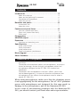
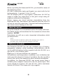
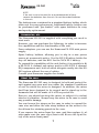
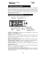
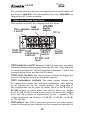
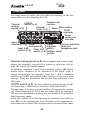
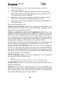
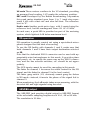
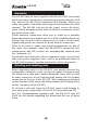
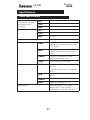
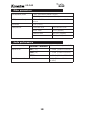
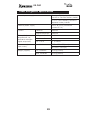
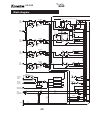
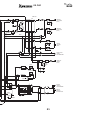
KS-342
4-channel mixer
Operating manual
� � �
� � �
���
���
�
�
�
� ��
�
� ��
���
�����
���
���
�
����
����
�����������������������
��
�
��
��
��
�
��
��
��
�
��
��
��
�
��
��������
��
�
����� �
���
�
�
���
���� ���� ��
����
���
���
���
���
���� ���� ��
����
���
���
���
���
���� ���� ��
����
���
���
���
���
���� ���� ��
����
���
���
���
���
����
�
���
�
���
�
���
���
�����
�
��
���
��
�
� � �
���
��
��
� � �
���
����������
���
KS-342
Introduction
Thank you for the purchase of the Kamesan KS -342 4-channel
portable mixer. This mixer is designed to provide you with the
most flexible and powerful features available in a small, easily
portable package.
Key points include:
A wide range of input options, including +48V phantom
powering
Switchable support for MS operation
AES/EBU digital output, together with a wide range of
balanced and unbalanced analog outputs with compression
Flexible monitoring
Further expansion possible through the Kamesan range of
modular audio components
Notes and warnings
The KS - 6001 may be used with a dry-cell battery pack or with a
NiCd NP-1 pack or with an external power source, as described
elsewhere in this manual. If the unit is used under different conditions, there is a risk of fire, damage to the unit, or personal
injury.
Note the following with regard to external power supplies:
Make sure the polarity of the external powering device is
correct.
Make sure it is properly connected to the KS-342. Damage
to units may result if connectors are not properly fitted and
the power is turned on.
Also, follow the common-sense precautions below:
Do not allow liquids to come into contact with the unit
or be spilled inside. Should this occur, fire, damage or
malfunction may result.
Make sure that no metal objects or easily inflammable
substances inadvertently get inside the unit through holes
or slots. Should this occur, fire, the unit may become
damaged or start to behave erratically.
Do not attempt to disassemble the unit as damage or
malfunction may result.
3
KS-342
Notes on the Operating Environment
Avoid using this unit in places with high heat or high humidity as damage or malfunction may result. When using in an
exceptionally cold environment, battery service life may be
shortened, and there may be a drop in performance. If at all
possible, use this unit in the temperature range as indicated in
the specifications.
When connecting this unit to external devices, be sure to read
all related operation manuals and connect the devices correctly
to each other. If there are mistakes in the connections, it is
possible that either the KS -342 or the other unit(s) will be damaged.
In the event that smoke or odors come from the unit, turn off
the power and remove all batteries and external power supply
sources at once. Contact your dealer or service representative.
In the event of damage or injury caused by accidents, improper
operation or functioning, the proper course of action shall be
determined according to our service regulations. Please note
that we cannot be responsible in any way for any loss of pre-recorded material.
4
KS-342
Contents
Introduction ............................................................3
Notes and warnings ....................................................... 3
Notes on the Operating Environment .............................. 4
Connection of Microphones............................................ 5
About the manual ......................................................... 6
Batteries and power ................................................6
Accessories, etc. .......................................................... 7
About the case ............................................................. 7
Features and panel items ........................................9
Left side (viewed from front) .......................................... 9
Right side (viewed from front)........................................ 10
Front panel ................................................................... 12
MS operation...........................................................15
AES/EBU output ......................................................15
Expansion ...............................................................16
Attaching and detaching units ........................................ 16
Specifications .........................................................17
Audio specifications ...................................................... 17
Other parameters.......................................................... 18
Audio performance........................................................ 18
Power and general specifications .................................... 19
Block diagram .........................................................20
About Kamesan.......................................................22
Connection of Microphones
WARNING
Connection of microphone cables and microphones: to prevent
hazard or damage, ensure that only microphone cables and
microphones designed to the IEC 268-15A standard are
connected.
Connexions des microphones et de leurs câbles: pour éviter
tout endommagement, s’assurer de brancher uniquement des
microphones et des câbles de microphones conçus selon la
norme IEC 268-15A.
When using microphones, make sure that the phantom power
is set appropriately for the microphones. Use of +48 V phantom
power with microphones not designed for this may result in
damage to the microphones, and to the Kamesan KS -342.
In the event of encountering problems with the Kamesan KS 342, you should contact your local after-sales representative.
5
KS-342
Before operating the Kamesan KS -342, you should be aware of
the following points:
All XLR-3 connectors (male and female) are wired with the following pinouts: 1=ground, 2=hot, 3=cold.
The AC adaptor jack is a tip-negative connection. DO NOT attempt to make any connection to this jack except using AC
adaptors authorized by Kamesan.
Always remove any dead batteries immediately from the
Kamesan KS -342, and remove any batteries from the unit if it
will not be used for some time. Corroded and leaking batteries
can cause severe damage to the unit.
About the manual
Keep this manual in a convenient location for handy reference.
Any labels on the unit mentioned in the manual are shown this
typeface: OUTPUT.
Sometimes you will see a note—important information which
you should note.
NOTE
Failure to read and observe notes and warnings may result in
personal injury and/or possible damage to the unit.
Batteries and power
The Kamesan KS -342 can use any standard type of battery:
manganese, alkaline, nickel-cadmium, nickel-hydride cells fitted in a BP-3/8 battery holder (supplied with the KS -342) or a
special NP-1 NiCd battery pack.
Eight type 3 (AA) size batteries are required.
In normal use and temperature conditions, a set of alkaline batteries provides about six hours of operation. See the specifications at the end of this manual for more detailed information.
In addition, the Kamesan KS -342 can accept power from a
suitable power adaptor connected to the DC power input. This
power should be between 10 V and 15 V DC, with a maximum
current of 500 mA. The connector is tip negative.
6
KS-342
NOTE
If the unit is not to be used for an extended period of time,
remove the batteries from the unit. Do not leave dead batteries
in the unit.
The batteries are contained in a standard battery holder, which
slides out for easy replacement. Additional battery holders can
be purchased and “pre-loaded” with spare batteries for easy
and speedy replacement.
Accessories, etc.
The Kamesan KS -342 is supplied with everything you need to
start work.
However, you can purchase the following, in order to increase
the capabilities and the functionality of the unit:
Power adaptors: you can use the Kamesan PS -M12 mini power
supply.
Spare battery holders, allowing you to slip in a new power
source at a moment’s notice. Use the BP-3/8 battery holder for
dry cell batteries, and the BH-1 for the NiCd NP-1 battery.
To expand the capabilities of the unit further, it is possible to fit
a KS - 6001 4-channel sub-mixer, and/or a KS - 6002 4-channel
EQ/compressor unit, both of which integrate neatly into the KS 342 system without the use of cables.
Consult your Kamesan supplier for details.
About the case
The Kamesan KS -342 case is designed to hold and protect the
unit against any wear and tear under the standard conditions
of use for which the mixer is designed. In addition, the mixer
itself has been designed to be rugged and to stand up to the
demands that will be made of it in its expected life.
Even so, you should not drop the mixer, or subject it to violent
shocks or vibration. Always keep the mixer in its case to avoid
any possible damage.
You can loosen the straps on the case in order to expand the
case size and allow the side strap holders on the mixer to be
freed from the retaining panels in the case.
If you remove the mixer from the case, and then replace it, always make sure the case clips (four in all) fit over the lip at the
top of the mixer front panel.
7
KS-342
The touch fasteners at either side may be used to tidy cables, as
well as to restrain the mixer in its case.
You can use the pocket in the case to store spare batteries,
adaptors, etc.
You can secure the top flap using the touch fastener when it is
folded back to allow operation of the front panel. In addition, it
can form a convenient rain hood, allowing easy access to the
front panel controls while protecting them from the elements.
Also note that if the KS - 6001 sub-mixer or the KS - 6002 EQ/
compressor is fitted, cushioning material is supplied, allowing
the extra units to fit snugly, and minimizing any possible damage caused by shock or vibration.
8
KS-342
Features and panel items
For the most part, the explanations given for the individual
parts of the KS -342 will allow you to operate the mixer effectively. You should therefore read this part of the manual carefully in order to understand the many features and operations
possible with the unit.
Left side (viewed from front)
This section is chiefly the inputs to the mixer:
�������
���������������
�������������������
��
���
��
�� �� �
�
���
���
��
� ��
�
�� � �
���
����
����������
��������� �������
������ ������������
�����
������
��������������
INPUTS 1 through 4 Connect the microphones or line level
sources to these XLR jacks.
INPUTS 1+2 This XLR-5 jack is used to connect a stereo microphone to the 1 and 2 inputs. The wiring is: 1= ground, 2=L
+, 3=L –, 4=R +, 5=R –.
Battery locking lever Pull down to release the battery pack
Coaxial power supply Connect a suitable power supply (tip
negative, between 10 V and 15 V, approximately 0.5 A).
DC 12 V OUT This connector is used to supply external power
to other equipment.
AUX IN This connector is used to connect an auxiliary input,
such as a camera’s audio signal, etc.
Aux level control and routing switch The level control is
used to set the level of the input aux signal when it is routed to
the output busses.
9
KS-342
The routing switch sends the aux signal to the L and R main output busses (AUX MIX) or to the monitor bus only (AUX MONI) or
completely off (center position).
Right side (viewed from front)
This section is chiefly the outputs from the mixer:
��������
��������
������
�����
����
������������� ������
�������
�������
������ ������
���
�����
��
�
�
���
�
���
��� ��
�
� �
�������
��
�
���
���
���
���
����������������
������
���
������
���
�����
���
���
� �� � ���
� ��� � ����������
�����������������
�����������������
���������������
�������
����������������
�������� ����������� �������
������
��������
�����������
�����
��������
������
MAIN outputs L and R Balanced XLR-3 connectors providing
the main analog output signals from the KS -342. They can also
be used to provide the outputs from input channels 1 and 2, for
example when these are used in MS mode.
MAIN level controls Use these rotary controls to adjust the
level of the signals sent from the main outputs.
MAIN compressor controls The main output busses can
be compressed using the onboard compressor (this applies
to all outputs fed by the output busses. The triggering of
the compressor can be done by either the L or the R bus, or
ST LINK setting, in which either bus can be above the trigger
level, or L•R in which both busses must be above the trigger
level (the off position is represented by the • symbol). The
trigger level itself can be set to +3 dB (3), +6 dB (6), +9 dB (9)
or +12 dB (12).
SUB output This XLR-5 connector provides the main output
busses as balanced sub outputs (or this connector can also be
10
KS-342
used as direct outputs from channels 3 and 4). The wiring is:
1 = ground, 2=L+, 3 = L–, 4=R+, 5=R–. There is a choice of output
levels: –20 dB or –60 dB, selectable by the switch immediately
below this connector.
ST OUT This unbalanced 3.5 mm stereo jack output provides
another stereo output for feeding unbalanced inputs (on a
camera, for example). The level is –60 dB.
SOURCE SELECT switch This allows the choice of whether
the MAIN and SUB connectors above output the mixed left and
right output busses (MIX), or whether they output the individual
channels in pairs (DIRECT OUT).
AES/EBU The KS -342 is capable of outputting the stereo output
in AES/EBU format. The sampling frequency is selectable with
the rotary switch beside the XLR-3 outputs at either 44.1K,
48K or 96K (all Hz). The • position represents the off position
(no digital signal is output).
NOTE
When this digital output is enabled, it uses battery power. If you
are not using it, make sure that the switch is in the off position,
to extend the life of the batteries.
DC IN Use this to connect a DC power supply, providing between
+10 V and +15 V at no more than 600 mA. Wire the connector as
marked on the panel.
11
KS-342
Front panel
The front panel is where you will make the majority of the settings while you are using the KS -342.
�������������
��������
��������
��������
������������
��������
������������
��������
������������
������
�����������
�����
���������
���
���
������
�����������
���������
������
������
�������������� ������
�������������������
����������
����������
����������
������
�����������
��������������
�����������
�������������
������������ ��������������
������
� � �
���
���
�
�����
�
�
�
�
�
��
� � �
�
���
��
��
� � �
���
��
�
� � �
���
���
���
���
� ��
�
� ��
����
�����
���
���
�
����
����
�����������������������
��
�
��
��
��
�
��
��
��
�
��
��
��
��
�
��������
��
�
����� �
���
�
�
���
���� ���� ��
����
���
���
���
���
���� ���� ��
����
���
���
���
���
���� ���� ��
����
���
���
���
���
���� ���� ��
����
���
���
���
���
���
����������
Channel routing switch (x 4) Each channel has a switch that
allows the channel’s output to be routed to either the left (L),
right (R) or both (C) output busses.
In addition, channels 1 and 2 have another setting: MS, which
allows these channels to be operated in MS mode (with a
stereo microphone, for example). Both the 1 and 2 channels
must be set to MS, and various other features of the mixer also
change. These are detailed in the section later referring to the
MS mode.
LCF/PFL switch (x 4) Use this control to sweep the low-cut filter frequency (–12dB/octave) between 20 Hz and 200Hz.
Though there is no way to turn this filter off, in practice, setting
the cutoff frequency to 20 Hz has the same effect as turning it
off, as most microphone systems are not sensitive to sounds in
that frequency range.
Press this control (it is non-latching) to perform a pre-fade listen (PFL) on the channel (the level is shown on the right meter).
More than one of these PFL controls can be pressed at the same
12
KS-342
time, but in this case, the level and right VU meter indication
will be lower than the actual values.
Channel faders The nominal position is at about the 2 o’clock
position, when the fader is pointing to the channel number.
NOTE
In MS mode, faders 1 and 2 have a slightly different meaning, as
explained in the appropriate section.
Slate microphone This built-in microphone allows the operator to make comments, or clapperboard, etc. signals to be added to the main mix.
Input selector (x 4) Use this to select between the following:
P48 Condenser microphones requiring +48V phantom powering
Dy-M Dynamic microphones
LINE Line-level sources
A-B - A-B type microphones
NOTE
Ensure that only microphones corresponding to the selection
are connected to the appropriate inputs, otherwise damage may
occur to the KS-6001 and to the microphones.
Input trim control (x 4) Used to adjust the level of the signal
fed to each channel. The amount of trim depends on the input
setting: the blue figures indicate line-level settings, and the
white figures indicate microphone levels.
Fader link (FD LINK) switch (x 2) When these switches are
on (pushed to the right position), the even-numbered faders
control the levels of the two linked channels (not in MS mode).
Battery check button When the unit is turned on, pressing
this momentary non-latching button allows you to check the
battery health using the left meter. The further the meter is deflected, the more life there is in the batteries.
Meter light/Oscillator switch This switch serves two functions. In its up position, the meters are illuminated.
In the down position, the built-in 1 kHz line-up oscillator is activated (together with the meter light). In order to see the output
level using the oscillator:
1.
Make sure that both the OUTPUT level switches are set to
the correct value (usually +4).
13
KS-342
2.
Turn the power on (up), and then turn the oscillator
switch on (down).
3. To monitor both channels together, set the monitoring
selection switch to the L/R setting (for an explanation of
the monitoring switch settings).
4. Adjust the level of the outputs so that the meter reads 0
dB (or the equivalent, depending on the meter.
5. Remember to turn the oscillator off when the adjustment
has been made.
The center position is off.
Master level controls Adjust the output level with these controls. These are recessed to avoid accidental changes to the
output level in normal operation.
Monitor selection, level and headphone jack Select the
signals monitored through the headphones using the monitor
selection control. AUX selects the auxiliary signals, L selects the
left, and R selects the right output bus, L/R is stereo and L+R is a
mono combination of the left and right busses. Note that these
assignments change in MS mode, as explained below.
Use the level control to set the monitoring level as heard through
the headphones, plugged into the standard 1⁄4" stereo jack.
Power switch and indicator Turn the unit on by pushing the
switch up. The indicator lights green when the internal batteries
are used, and orange when an external power supply is used.
It flashes when the battery level becomes low. When it flashes,
you should replace the batteries.
COMP indicator Lights when the compressor is in operation,
as switched from the side panel.
NOTE
The compressors use battery power. Turn the compressors off
when you do not need them to extend the life of your batteries.
SLATE button Push to activate the slate function with the internal microphone.
Meters There are three different types of meter available with
the KS -342. These are factory-fitted and are not user-replaceable, depending on the model of your KS -342, you may have
one of the following types of meter fitted:
14
KS-342
VU scale These meters conform to the VU standard, providing
an averaged level reading. 0 VU marks the reference position.
BBC scale Developed by the British Broadcasting Corporation,
this peak meter standard goes from 1 to 7 (each step represents 4 dB) with a fast rise and slow fall time. The reference
level is “6”.
Nordic scale Another peak meter type, with 0 again being the
reference level, but the readings are from –42 to +12 dBu.
In each case, a peak LED is provided as part of the metering
system, which lights at 6 dB below maximum level.
MS operation
MS operation is usually carried out using a specialized microphone designed for this kind of recording.
To use the MS facility with channels 1 and 2, make sure that
both channels 1 and 2 have their output destination selected
as MS.
Note that the dedicated XLR-5 connector can be used with appropriately-wired microphones in this mode. It provides phantom power, etc. in exactly the same way as the XLR-3 connectors, and the line selector switches, etc. should be set appropriately.
The AUX inputs cannot be used for cascading in this mode.
The fader for channel 1 becomes the width control for the MS
signal, and the fader for channel 2 is the level control.
The fader gang switch (1-2) obviously cannot gang the faders
in MS mode—instead, it inverts the phase of the signal fed to
channel 2.
When monitoring, the L+R mode takes a new meaning, with the
decoded left and right signals being decoded.
AES/EBU output
The AES/EBU jack provides digital output in AES/EBU format,
at the selectable sampling frequencies of 44.1, 48 or 96 kHz.
The resolution is 20 bits.
15
KS-342
Expansion
The KS -342 may be used together with the KS - 6001 sub mixer,
which provides a further four channels of input feeding the AUX
bus, and/or the KS - 6002 compressor/EQ module, which provides sweepable 2-band EQ and compression facilities for each
channel. The KS -342 can act as the power source for these
units, which integrate neatly with the built-in connector on the
top panel of the unit.
These modular connectors allow you to build up a portable
Kamesan system in a similar way to a child’s building block set,
without the need for other connectors or cables, as all audio
signals and power are carried by these built-in connectors.
There is no need to make any switch assignments on any of
the units—for example, when the KS - 6002 is connected, the
compressors and EQ circuits are automatically inserted into
the channels, etc.
You should note that since these expansion units do not have
their own power supplies, there will be an additional drain on
the KS -342 batteries, and the battery life will be shortened.
Attaching and detaching units
When attaching units to the KS -342, you should remove the
rectangular connector cover on the top panel, keeping it and
the screws in a safe place before fitting the other unit, so that
its male connector on the bottom plate mates with the female
connector on the top of the KS 342. The locating pins situated
on the bottom of the other unit should match the locating holes
on the top panel of the KS -342.
To detach a sub-unit from the KS -342, move both locking levers on the top center sides of the KS -342 forwards and lift.
See the documentation supplied with the KS - 6001 and KS 6002 for full details regarding the fitting and the use of these
units.
16
KS-342
Specifications
Audio specifications
Input levels (all
continuously variable
and electronically
balanced)
Input impedance
MIC
–70 to –30 dBs
LINE
–20 to +4 dBm
AUX
–20 to +4 dBm
MIC
3.0 kΩ
LINE
600 Ω
AUX
10 kΩ
Headroom
Analog output levels
Maximum output levels
32 dB (pre-fader input)
MAIN
+4/0/–20/–60 dBm switchable
(600Ω load) transformer balanced
XLR-3 type
SUB
–20/–60 dBm switchable (600Ω
load) electronically balanced XLR-5
type
UNBAL
–60 dBs (10 kΩ load) 3.5 mm
unbalanced stereo jack
MONI
0 dBs/50Ω (max load 8 Ω)
MAIN
+24 dBm (600Ω load, +4 selected
@ 12 V)
+20 dBm (600Ω load, +4 selected
@ 8 V)
SUB
–+8 dBm (600Ω load, –20 selected
@12V)
UNBAL
–60 dBs (10 kΩ load) @ 12 V
MONI
+6 dBs (50 Ω load, @ 12 V)
Digital output
AES/EBU format, XLR-3 type
connector. FS: 44.1/48/96
(selectable), resolution, 20 bits
17
KS-342
Other parameters
Microphone power
P-48V (maximum power 10 mA)
A-B 12V (maximum power 30 mA)
LCF (low-cut filter)
20 Hz — 200 Hz, continuously variable, –12 dB/
octave
Oscillator
1 kHz (±10%)
Compressor
Threshold level
+3/+6/+9/+12 dB
Attack time
2 ms (approx)
Release time
300 ms (approx)
Ratio
2:1 (approx)
Audio performance
Frequency response
MAIN OUT & SUB OUT 30 Hz — 40 kHz (within 1 dB)
Noise level
MIC (–70)
< –54 dB (22 kHz LPF/RMS)
LINE (+4)
< –70 dB (22 kHz LPF/RMS)
MONI
< –65 dB (22 kHz LPF/RMS)
Total Harmonic Distortion (THD)
<0.1% (50 Hz — 15 kHz
+4 dBm)
18
KS-342
Power and general specifications
Internal power supply
8 x type 3 (AA) dry-cell batteries,
carried in standard battery holder
1 x NP-1 NiCd battery, carried in
optional battery holder
External power supply
+10 V to +15 V (maximum
current 0.5 A)
Current
Nominal
160 mA
Digital output on
240 mA
Battery life (normal
temperature, no
additional modules,
digital output off)
Manganese cells
> 4 hours
Alkaline cells
> 8 hours
NP-1 NiCd
> 12 hours
Dimensions (excl.
protrusions)
wxdxh
215 x 170 x 60 (mm)
Weight (approx)
inc. batteries
2.4 kg (5.3lbs)
excl. batteries
2.0 kg (4.4lbs)
8.5 x 6.7 x 2.4 (in)
19
KS-342
Block diagram
�����������
���
�
�����
�������
�
��
�
������
��
��
�
��������
���
����
����
����
�����
�
�������������
�����������
�
��
�
��
����
���������
����
�
�
�����
�
��
�����
�������
�
�
�����
�
�
���������
�
�
��
��������
���
����������
���
�
�����
�������
�
��
��
�
��
������
��
�
��
���
����
����
����
�����
�������������
�����������
����
���������
����������
���
�
�����
�
��
�
��
������
��
�
�������
��
����
����
�������������
�����������
����
�������
���������
����������
���
�
�����
�
��
������
��
�
��
�
�������
���
����
����
����
�����
�������������
�����������
����
���������
������������
���������
���
�������������
���������������
����������
����
��������������
�������
��������
���������
���������������
���������
�����
����������
��
���������
����������
������������
���
����������
�������������
�����
���
������
�����������
�����
���
�����
���������
�����
�����
�������������
���������
�������
�������
��
���
20
���
���������
����
���������
����
�����
���
����������
���
��
���
���
�����
����
��
��
����������
���������
���
�
���
����
�
���������
�����������������
��
�
�������
���
���
�������
����
����
����
��
����������
�
�����
��
���
����������
�
�
������
�����������������
�
���
��
�
����������
���������
�������
���
���
�����
������
���
������
���
����������
�
���
���
�������
���
������������
�������
����������
�
���
��
�������������
��������
�����������������
��
���������
���������
KS-342
���
�����������
���
�
�����
�����
�������
���������
���������
�������
�������
���
������
���
������
�����������
���������
�����
���
���������
��
�������
��
���
�
���
�
���
��
���
�
���
�
���
��
���
��������
�����������
��
�����������������
��������
����������
��������������
��
��
��������
������������
�
21
KS-342
About Kamesan
Sigma Systems Engineering was started in 1972 to develop and design
professional mixers for studio and remote broadcast applications.
Today, following the “slow and steady” principle of the tortoise, we
have built up our sales and our reputation to the extent that we now
enjoy 95% of the Japanese portable mixer market.
We have concentrated on two or three main areas in our design philosophy: compactness, in an industry which was traditionally dominated
by large, heavy equipment; ease of use, since time is always of the essence in the environments where our products are used; and quality,
to match the needs that today’s broadcasters require.
Our head office is in Shinjuku, Tokyo, and as a small company, we
are happy to listen to the ideas for product improvement suggested by
you, the customers and users of our equipment.
Making steady progress (like a tortoise, but maybe a little faster!), we
hope to meet your requirements, now and in the future.
Visit both of our Web sites at http://www.kamesan.co.jp and
http://www.kamesan.info in order to find out more about what we’re
doing, and to let us know what you are doing with Kamesan products.
22
Sigma Systems Engineering Co. Ltd.
3-5-2 Okubo
Shinjuku-ku
Tokyo 169- 0072
JAPAN
Tel: +81 3 3204 2611
Fax: +81 3 3204 2250
e-mail: [email protected]