1
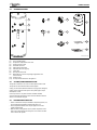
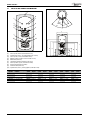
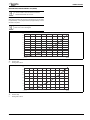
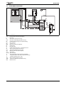
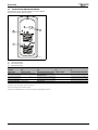
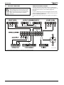
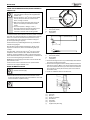
INSTALLATION AND MAINTENANCE INSTRUCTIONS
TWIN COIL INDIRECT UNVENTED HOT WATER CYLINDER
GREENSTORE TC CYLINDER SERIES
6 720 645 752 (2012/05) UK
(T30.41634.02)
6 720 645 525-00.1O
150/180/210/250/300 LITRE
CONTENTS
CONTENTS
1
Key to symbols and safety precautions . . . . . . . . . . . . . . . . . . . 3
1.1
Explanation of symbols . . . . . . . . . . . . . . . . . . . . . . . . . . . 3
1.2
Safety instructions . . . . . . . . . . . . . . . . . . . . . . . . . . . . . . 3
2
Product details . . . . . . . . . . . . . . . . . . . . . . . . . . . . . . . . . . . . . . . . 4
2.1
Usage . . . . . . . . . . . . . . . . . . . . . . . . . . . . . . . . . . . . . . . . . 4
2.2
Intended use . . . . . . . . . . . . . . . . . . . . . . . . . . . . . . . . . . . 4
2.3
Equipment level . . . . . . . . . . . . . . . . . . . . . . . . . . . . . . . . . 4
2.4
Standard delivery . . . . . . . . . . . . . . . . . . . . . . . . . . . . . . . 5
2.5
Scaling/Corrosion protection . . . . . . . . . . . . . . . . . . . . . . 5
2.6
Description of function . . . . . . . . . . . . . . . . . . . . . . . . . . . 5
2.7
Physical and connection dimensions . . . . . . . . . . . . . . . . 6
2.8
Specification . . . . . . . . . . . . . . . . . . . . . . . . . . . . . . . . . . . 8
3
Installation . . . . . . . . . . . . . . . . . . . . . . . . . . . . . . . . . . . . . . . . .
3.1
Regulations . . . . . . . . . . . . . . . . . . . . . . . . . . . . . . . . . .
3.2
Handling . . . . . . . . . . . . . . . . . . . . . . . . . . . . . . . . . . . . .
3.3
Installation location . . . . . . . . . . . . . . . . . . . . . . . . . . . .
3.4
Solar connection diagram . . . . . . . . . . . . . . . . . . . . . . .
3.5
Installing the temperature sensors . . . . . . . . . . . . . . . .
3.6
Installation . . . . . . . . . . . . . . . . . . . . . . . . . . . . . . . . . . .
3.7
Electrical connections . . . . . . . . . . . . . . . . . . . . . . . . . .
10
10
10
10
11
12
13
16
4
Commissioning . . . . . . . . . . . . . . . . . . . . . . . . . . . . . . . . . . . . .
4.1
User information from the system installer . . . . . . . . .
4.2
Preparing for use . . . . . . . . . . . . . . . . . . . . . . . . . . . . . .
4.3
Setting the cylinder temperature . . . . . . . . . . . . . . . . .
19
19
19
19
5
Shutting down . . . . . . . . . . . . . . . . . . . . . . . . . . . . . . . . . . . . . . 19
5.1
Taking the cylinder out of use . . . . . . . . . . . . . . . . . . . . 19
6
Environmental protection/disposal . . . . . . . . . . . . . . . . . . . . 20
7
Inspection/Maintenance . . . . . . . . . . . . . . . . . . . . . . . . . . . . . 20
7.1
Recommendations for users . . . . . . . . . . . . . . . . . . . . . 20
7.2
Maintenance and repair . . . . . . . . . . . . . . . . . . . . . . . . 20
8
Spare parts list . . . . . . . . . . . . . . . . . . . . . . . . . . . . . . . . . . . . . . 20
9
The Guarantee . . . . . . . . . . . . . . . . . . . . . . . . . . . . . . . . . . . . . . 20
2
6 720 645 752 (2012/05)
KEY TO SYMBOLS AND SAFETY PRECAUTIONS
1
KEY TO SYMBOLS AND SAFETY
PRECAUTIONS
1.1
EXPLANATION OF SYMBOLS
WARNING SYMBOLS
Safety instructions in this document are framed and
identified by a warning triangle which is printed on a
grey background.
Electrical hazards are identified by a lightning symbol
surrounded by a warning triangle.
Signal words indicate the seriousness of the hazard in terms of the
consequences of not following the safety instructions.
• NOTICE indicates possible damage to property or equipment, but
where there is no risk of injury.
• CAUTION indicates possible injury.
• WARNING indicates possible severe injury.
• DANGER indicates possible risk to life.
IMPORTANT INFORMATION
1.2
SAFETY INSTRUCTIONS
POSITIONING AND CONVERSION
B Only competent installers must install, commission, and maintain this
equipment.
B Only use the cylinder for heating domestic hot water.
FUNCTION
B Observe these installation and maintenance instructions to ensure
correct operation.
B Never switch the electric immersion heater on if the cylinder is not full
of water.
B Never restrict the outlets of the safety valves.
THERMAL DISINFECTION
B Risk of scalding!
Caution should be taken at periods of thermal disinfection due to the
possibility of domestic hot water temperatures being in excess of
60 °C .
MAINTENANCE
B Recommendation for the customer: Arrange a maintenance and
inspection contract with a competent person. Have the heating
appliance and the DHW cylinder serviced annually.
B Always switch the mains off when servicing the system.
B Only use genuine spare parts.
Notes contain important information in cases where
there is no risk of personal injury or material losses and
are identified by the symbol shown on the left. They are
bordered by horizontal lines above and below the text.
ADDITIONAL SYMBOLS
Symbol
B
Æ
•
–
Meaning
a step in an action sequence
a reference to a related part in the document or to other
related documents
a list entry
a list entry (second level)
Table 1
Benchmark places responsibilities on both manufacturers and
installers. The purpose is to ensure that customers are provided with the
correct equipment for their needs, that it is installed, commissioned and
serviced in accordance with the manufacturer's instructions by
competent persons and that it meets the requirements of the
appropriate Building Regulations. The Benchmark Checklist can be used
to demonstrate compliance with Building Regulations and should be
provided to the customer for future reference.
Installers are required to carry out installation, commissioning and
servicing work in accordance with the Benchmark Code of Practice
which is available from the Heating and Hotwater Industry Council who
manage and promote the scheme.
Visit centralheating.co.uk for more information.
6 720 645 752 (2012/05)
3
PRODUCT DETAILS
2
PRODUCT DETAILS
2.1
USAGE
These cylinders are designed to accept input from two heat sources, the
most common being a solar input supported by a controlled appliance
such as a gas or oil boiler. The maximum cylinder heat input must not
exceed the following values:
Cylinder
TC-150
TC-180
TC-210
TC-250
TC-300
Max. cylinder heat input
31.9 kW
39.4 kW
Table 2
Where the combined heat input exceeds the maximum input stated,
precautions must be taken to limit the heating appliances to the
appropriate input (see installation instructions of the heating
appliance).
Correctly commissioned input reduces the cycling of the heating
appliance and reduces the cylinder heat-up time.
2.2
INTENDED USE
B Only use the cylinder for heating domestic hot water.
Any other application will be considered incorrect use. No liability for
any losses resulting from such use is accepted.
2.3
EQUIPMENT LEVEL
• 4x sensor pockets internal Ø = 20.4 mm
• Upper indirect coil for heating by the secondary heating appliance
• Lower indirect coil for heating using the primary heat source,
including solar input.
• All-round rigid insulation, free of CFC and HCFC.
• Duplex stainless steel cylinder
• Immersion heater, 3 kW
4
6 720 645 752 (2012/05)
PRODUCT DETAILS
STANDARD DELIVERY
4
AQU-16-3W
1
6
AQU-31-3W
2.4
AQUA-15-3W
9
2
AQU-17-3W
3
5
7
AQ
U-1
9-
3W
3W
-21-
AQU-18-3W
U
AQ
8
10
11
6 720 645 525-07.2O
Fig. 1
[1]
[2]
[3]
[4]
[5]
[6]
[7]
[8]
[9]
Twin Coil DHW cylinder
Temperature and pressure relief valve
Immersion heater, 3 kW
Tundish Ø 15/22 mm
Solar high limit thermostat
Cold water Inlet control group
2-Port valve
Dual cylinder thermostat
DHW expansion vessel incorporating fixing bracket with
connection hose
[10] Connection set
[11] Set of printed documents for the appliance
2.5
SCALING/CORROSION PROTECTION
The cylinder is made from corrosion-resistant Duplex stainless steel.
The cylinder can be used with all mains water supplies.
Scaling: In cases where the water hardness is very high (over 450 ppm)
a water softener must be used to protect the cylinder against rapid
development of scale.
Corrosion protection: Any water softener should be installed,
commissioned and maintained to ensure the water hardness after the
softener is never below 150 ppm.
2.6
DESCRIPTION OF FUNCTION
• If there is insufficient heat input available via the primary (lower) coil,
the secondary heating appliance will heat the upper coil.
• Due to temperature stratification only the upper section of the
cylinder will be heated.
• When hot water is being drawn off, the cylinder temperature in the
upper section drops by approximately 8 °C to 10 °C before the heat
source reheats the cylinder.
6 720 645 752 (2012/05)
5
PRODUCT DETAILS
2.7
PHYSICAL AND CONNECTION DIMENSIONS
5
6
7
7
4
3
8
2
2
15°
25°
35°
45°
45°
J
9
10
10
Cylinder
TC-150
TC-180
TC-210
TC-250
TC-300
Customer order part
numbers
7 716 800 542
7 716 800 543
7 716 800 544
7 716 800 545
7 716 800 546
A/mm
349.5
349.5
424.5
424.5
424.5
B/mm
404.5
404.5
479.5
479.5
479.5
C/mm
449.5
449.5
524.5
524.5
524.5
Fig. 3
D/mm
724
724
1028
1112
1112
E
C
A
D
F
G
Overview of connections
Sensor pocket, bottom (internal Ø 20.4 mm)
Cylinder flow / return - secondary appliance (Ø 22 mm)
Sensor pocket, centre (internal Ø 20.4 mm)
DHW secondary circulation connection (Ø 22 mm)
DHW outlet (Ø 22 mm)
Temperature and Pressure Relief valve (1/2")
Sensor pockets, top (x2, internal Ø 20.4 mm)
Immersion heater (Rp 1¾ female)
Cold water inlet (Ø 22 mm)
Cylinder flow / return - primary appliance/solar (Ø 22 mm)
AQU-25-3W
[1]
[2]
[3]
[4]
[5]
[6]
[7]
[8]
[9]
[10]
B
Fig. 2
H
AQU-24-3W
I
1
Physical and connection dimensions
E/mm
775
775
1079
1163
1163
F/mm
779
779
1083
1167
1167
G/mm
832
1032
1207
1407
1707
H/mm
950
1150
1325
1525
1825
I/mm
1285
1490
1665
1860
2155
J/mm
570
570
570
570
570
Table 3
6
6 720 645 752 (2012/05)
PRODUCT DETAILS
50
CLEARANCE DIMENSIONS
50
6 720 645 525-06.1O
180
80
50
Fig. 4
Recommended minimum wall clearances
6 720 645 752 (2012/05)
7
PRODUCT DETAILS
2.8
SPECIFICATION
Cylinder type Greenstore
WRAS No.
WRc No.
TC-150
TC-180
TC-210
TC-250
TC-300
1105064
1105064
1105064
1105064
1105064
ETC
15811
ETC
15811
ETC
15811
ETC
15811
ETC
15811
General characteristics
Dual thermostat setting
°C
10/70
10/70
10/70
10/70
10/70
Dual thermostat high limit
°C
85
85
85
85
85
Temperature and Pressure relief valve
°C
90
90
90
90
90
Temperature and Pressure relief valve
bar
7
7
7
7
7
Maximum operating pressure
bar
5.5
5.5
5.5
5.5
5.5
Minimum operating cold mains pressure
bar
1.5
1.5
1.5
1.5
1.5
Expansion valve setting
bar
6
6
6
6
6
Size of expansion vessel supplied
l
18
18
18
25
25
Expansion vessel charge pressure
bar
3
3
3
3
3
Weight (dry, excl. packaging)
kg
35.6
38.1
44.6
48.9
53.0
Packaged weight
kg
50
53
60
65
69
Weight full of water
kg
200
231
264
298
348
kWh/d
1.27
1.31
1.42
1.52
1.93
- total
l
158
187
211
241
287
- excl. solar heating
l
93
122
106
126
172
Dedicated solar volume
l
65
65
105
115
115
Standby heat loss (24 h)
Cylinder capacity:
Available capacity
Upper indirect coil (secondary heat source)
Heating water content
l
3.0
3.0
4.1
4.1
4.1
Heat exchanger surface
m2
0.657
0.657
0.845
0.845
0.845
120
Maximum heating water temperature
°C
120
120
120
120
Maximum operating pressure inside the upper indirect coil
bar
6
6
6
6
6
Heat exchanger power (80-60 °C / 10-40 °C)
kW
31.9
31.9
39.4
39.4
39.4
Heat-up time 100% (15-60 °C)
min
14
17
12
13
24
Primary flow rate
l/h
1375
1375
1698
1698
1698
mbar
150
150
300
300
300
Pressure drop
Lower indirect coil (primary heat source/solar)
Heating water content
l
3.0
3.0
4.1
4.1
4.1
Heat exchanger surface
m2
0.657
0.657
0.845
0.845
0.845
130
Maximum solar fluid temperature
°C
130
130
130
130
Maximum operating pressure inside the lower indirect coil
bar
6
6
6
6
6
Heat exchanger power (80-60 °C / 10-40 °C)
kW
31.9
31.9
39.4
39.4
39.4
Primary flow rate
l/h
1375
1375
1698
1698
1698
mbar
150
150
300
300
300
Pressure drop
Immersion heater (BS225) (EN60335-2.73)
Electrical power supply
230 V - 50 230 V - 50 230 V - 50 230 V - 50 230 V - 50
Hz
Hz
Hz
Hz
Hz
Maximum current drawn
A
13
13
13
13
13
Electrical power
W
3000
3000
3000
3000
3000
Minimum breaking capacity
A
13
13
13
13
13
Protection index
IP
21
21
21
21
21
l
59.5
89.7
70.2
87.7
133.9
min
80
124
86
138
180
Volume heated by immersion heater
Heat up time to 65°C
Table 4
CONSTANT DHW OUTPUT
The constant DHW output shown in the specification refers to the
following:
• Flow temperature 85 °C
• Outlet temperature 45 °C
• Cold water inlet temperature 10 °C
• Maximum heat input (heat source input at least the same as the
cylinder coil output)
8
Reducing the specified heat input will result in a reduction in the
constant DHW output and the performance factor (NL).
6 720 645 752 (2012/05)
PRODUCT DETAILS
PRESSURE DROP, INTERNAL INDIRECT COIL (IN BAR)
When calculating the pressure drop in the solar circuit:
B Take the influence of the antifreeze used and the
manufacturer's details into account.
Example:
With a water/propylene-glycol mixture of 55/45 (frost protection down
to approximately – 30 °C), the pressure drop is approximately 1.3 times
the value for tap water.
Pressure drop values resulting from the mains are not
taken into account in the diagram.
Δp/mbar
200
180
160
140
120
100
80
60
40
20
0
0
200
400
600
800
1000
1200
1400
Fig. 5
Δp
.
V
.
1600
.
2000
V/l/h
6720645 525-08.1O
TC-150 and TC-180
Pressure drop
Heating water volume
Δp/mbar
400
350
300
250
200
150
100
50
0
0
6720645 525-09.1O
Fig. 6
Δp
.
V
200
400
600
800
1000
1200
1400
1600
1800
V/l/h
TC-210, TC-250 and TC-300
Pressure drop
Heating water volume
6 720 645 752 (2012/05)
9
INSTALLATION
3
INSTALLATION
3.1
REGULATIONS
This System has been approved to the Building Regulations for unvented
hot water storage systems and the Local Authority must be notified of
the intention to install. Therefore the installation must be carried out by
a person competent to install unvented hot water systems.
The installation must be carried out in accordance with the following
recommendations:
• All current Building Regulations issued by the Department of the
Environment, i.e. Approved Document L1 Building Standards
(Scotland) (Consolidation) Regulations issued by the Scottish
Development Department UK Water Regulations/Byelaws (Scotland)
• Health & Safety Document No. 635 (The Electricity At Work
Regulations 1989)
The installation should also be in accordance with the following British
Standard Codes of Practice:
• BS 5449:1990 Forced circulation hot water systems
• BS 5546:2000 Installation of hot water supplies for domestic
purposes
• BS 5918:1989 Solar heating systems for domestic hot water
• BS 6700:2006 Design, installation, testing and maintenance of
services supplying water
Failure to install this appliance correctly could lead to prosecution and
will invalidate the guarantee. It is in your own interest and that of safety
to ensure that the law is complied with.
Manufacturer's instructions must NOT be taken in anyway as over-riding
statutory obligations.
This appliance meets the requirements of IPX4D, i.e. degree of
protection against moisture.
Reference should be made to Criteria for gas fired combination boilers
used as after heaters in solar thermal systems and BRE Solar heating
UK:1981.
3.2
HANDLING
B Never set the cylinder down hard during handling.
B Only remove the cylinder from the packaging at the installation
location.
3.3
INSTALLATION LOCATION
CAUTION: Damage through stress cracks.
B Install the cylinder in a room that is free from the risk
of frost.
B Maintain the minimum clearances
(Æ Fig. 4 on page 7).
B Install the cylinder on a level floor with sufficient load-bearing
capacity.
B If installing the cylinder in wet rooms, position it on a suitable
platform.
10
6 720 645 752 (2012/05)
INSTALLATION
3.4
SOLAR CONNECTION DIAGRAM
T1
TDS
WW
HP
230V AC
TWM
FK
SV1
SP
GSP
SWC
TB
230V AC
5
M
MAG
SF
ICS
SV2
M
T2
RV
E
S...solar
DM
RV
RE
6 720 645 525-03.1O
KW
Fig. 7
DM
E
FK
GSP
HP
ICS
KW
MAG
RE
RV
SF
SP
SV1
SV2
SWC
S...solar
TB
T1
T2
TDS
TWM
WW
Pressure reducing valve (G3 kit supplied)
Drain valve
Solar collector (optional accessory)
Greenskies solar package (optional accessory)
Circulation pump (heating circuit/cylinder heating)
Inlet control set
Cold water inlet
Expansion vessel (G3 kit supplied)
Isolating valve
Non-return valve
Cylinder temperature sensor - secondary heat source
Solar circuit pump (optional accessory)
Temperature and Pressure relief valve
Expansion relief valve (G3 kit supplied)
Terminal box
Twin coil cylinder
Solar system high limit thermostat (G3 kit supplied)
Temperature sensor, solar collector (optional accessory)
Cylinder temperature sensor - solar
Solar controller (optional accessory)
Thermostatic DHW mixer (optional accessory)
DHW connection
6 720 645 752 (2012/05)
11
INSTALLATION
3.5
INSTALLING THE TEMPERATURE SENSORS
The temperature sensors and safety equipment are fitted in different
locations on the cylinder, subject to system.
3
2
1
6 720 645 525-05.1O
Fig. 8
[1]
[2]
[3]
Overview of connections
Lower sensor pocket
Centre sensor pocket
Upper sensor pocket
Solar thermal
yes
system?
System type
S-plan or Y-plan
Upper sensor pocket 1 Solar high limit thermostat
Upper sensor pocket 2 2nd solar sensor1)
Centre sensor pocket Dual cylinder thermostat
Lower sensor pocket Solar sensor 1
yes
no
with internal three-way valve S-plan or Y-plan
Solar high limit thermostat and
–
2nd solar sensor 1)
Dual cylinder thermostat 2)
–
Cylinder temperature sensor 3) Dual cylinder thermostat
Solar sensor 1
–
no
with internal three-way valve
–
Dual cylinder thermostat2)
Cylinder temperature sensor3)
–
Table 5
1) 2nd solar sensor is required for some solar installations
2) Only the temperature limiter will be connected
3) Part of the standard delivery of the internal three-way valve (heating appliance accessory)
12
6 720 645 752 (2012/05)
INSTALLATION
3.6
INSTALLATION
All hydraulic cylinder connections are suitable for 22 mm
pipes.
B Make connections with the compression fittings
supplied.
3.6.1 CONNECTION OF THE SECONDARY APPLIANCE
B Connect to the upper coil (Æ fig. 2 [2], page 6) using the
compression fittings supplied, either connection can be flow or
return, performance is identical either way. The heating circuit must
be positively pumped as gravity circulation is not possible.
B The heating circuit can be open vent or sealed system to a maximum
pressure of 6 bar. If the heating circuit is sealed an expansion vessel,
pressure gauge and pressure relief valve will be required if not already
part of the heating appliance.
B The heating appliance may be gas, oil or electric but must be under
effective thermostatic control. Uncontrolled heat sources such as
some AGAs, back boilers and solid fuel stoves are not suitable.
B Caution must be taken to prevent an air lock at time of commissioning
the unit, an air vent may be required.
B The coil must be able to be drained via a suitable valve.
3.6.2 CONNECTION OF THE PRIMARY APPLIANCE OR SOLAR
SYSTEM
B Connect to the lower coil (Æ fig. 2 [10], page 6) using the
compression fittings supplied, either connection can be flow or
return, performance is identical either way. The heating/solar circuit
must be positively pumped as gravity circulation is not possible.
B The heating/solar circuit can be open vent or sealed system to a
maximum pressure of 6 bar. If the heating/solar circuit is sealed an
expansion vessel, pressure gauge and pressure relief valve will be
required if not already part of the heating appliance or solar system
equipment.
B The heating appliance may be gas, oil or electric but must be under
effective thermostatic control. Uncontrolled heat sources such as
some AGAs, back boilers and solid fuel stoves are not suitable.
B A solar system must be provided with a suitable controller and means
of thermostatic control with the solar sensors being fitted as per
TAB. 5, page 12, of this manual and the control manufacturer's
instructions.
In solar installations the mixing ratio of glycol & water
may increase the pressure drop through the coil.
B Caution must be taken to prevent an air lock at time of commissioning
the unit, an air vent may be required.
B The coil must be able to be drained via a suitable valve.
6 720 645 752 (2012/05)
3.6.3 CONNECTION ON THE WATER SIDE
B Install the cold water inlet control group with the compression fittings
supplied. The mains supply must be able to provide the minimum
pressure and flow rates stated in specification table TAB. 4, page 8.
B The cold water inlet control group includes a 6 bar expansion relief
valve. A discharge pipe must be installed and routed via a tundish in
accordance with current regulations.
NOTICE:
B When draining either the domestic hot water system
or the cylinder ensure the cold water supply is isolated
and that at least two hot water draw off points are
opened. One of these hot water draw off points must
be the one closest to the cylinder in height terms.
The drain valve installed at the cold water supply inlet
to the cylinder should be used, where practicable.
CAUTION: Damage through excess pressure.
B Never restrict the outlets of any safety valves.
B Install a drain valve at the cold water inlet.
3.6.4 DHW SECONDARY CIRCULATION
Cylinders are equipped with a DHW secondary return connection.
B If no DHW secondary circulation is required, blank off and ensure a
water tight seal (Æ fig. 2 [4], page 6).
Seal and insulate the connection.
B When connecting DHW secondary circulation:
Install a DHW circulation pump approved for potable water and a
suitable non-return valve.
Due to the possibility of heat losses, DHW secondary
circulation is only recommended in conjunction with a
DHW secondary circulation pump that is time or
temperature-controlled. The circulation circuit must be
properly insulated.
To ensure safe DHW outlet temperatures thermostatic
mixing valves may be required. Guidance must be taken
from current regulations.
THERMAL DISINFECTION
Guidance must be taken from current regulations to ensure the risk of
Legionella bacteria growth is prevented.
13
INSTALLATION
3.6.5 DHW EXPANSION VESSEL
B Connect the expansion vessel using the hose supplied to the cold
water inlet control group.
For DHW systems with a large volume:
B Check whether the expansion vessel supplied (18 or 25 litres) is
adequate and if required, install an additional expansion vessel in
parallel to the one supplied, ensuring the air charge of each is
identical.
WARNING: Risk of scalding!
Hot water can lead to severe scalding.
B Route the discharge pipe work so that any discharged
hot water or steam cannot create a risk.
B Locate the cold water inlet control group so that any water flowing
from the expansion relief valve will be drained together with any water
discharged from the temperature and pressure relief valve.
B Route the discharge pipework in accordance with part G3, schedule 1
of the Building Regulations (the following includes the most important
requirements of the Building Regulations).
B Install the tundish vertically in direct proximity to the cylinder
(maximum distance between safety valves and tundish 600 mm).
B The discharge pipe work must be of a material capable of
withstanding the potential temperatures and pressures.
B The following applies for the discharge pipe work downstream of the
tundish:
– Minimum 300 mm vertical drop before the first bend.
– Must be at least one pipe size larger than the inlet of the tundish.
– Route the discharge pipe work with a constant fall.
3.6.7 DISCHARGE ARRANGEMENT
A
B
300 mm
minimum
F
C
Fig. 9
A
B
C
D
E
F
14
The two safety valves will only discharge water under fault conditions.
When operating normally water will not be discharged.
The tundish should be vertical, located in the same space as the
unvented hot water storage system and be fitted as close as possible and
within 600 mm of the safety device e.g. the temperature relief valve.
3.6.6 INSTALLING THE DISCHARGE PIPE WORK FROM THE
SAFETY VALVES SUPPLED
600 mm
maximu
m
Position the inlet control group so that the discharge from both the two
safety valves can be joined together via a 15 mm end feed Tee. Connect
the Tundish and route the discharge pipe. The discharge pipework must
be routed in accordance with Part G3 of schedule 1 of the Building
Regulations. The information that follows is not exhaustive and if you are
in doubt you should seek advice.
D
E
Diagram of a typical discharge pipe arrangement (extract from
Building Regulation G3)
Safety device (e.g. temperature relief valve)
Metal discharge pipe (D1) from temperature relief valve to
tundish
Discharge pipe (D2) from tundish with continuous fall
Fixed grating
Trapped gulley
Tundish
The discharge pipe (D2) from the tundish should terminate in a safe
place where there is no risk to persons in the vicinity of the discharge
and:
• Be at least one pipe size larger than the nominal outlet size of the
safety device unless its total equivalent hydraulic resistance exceeds
that of a straight pipe 9 m long i.e. discharge pipes between 9 m and
18 m equivalent resistance length should be at least two sizes larger
than the the nominal outlet size of the safety device, between 18 and
27 m at least 3 sizes larger, and so on. Bends must be taken into
account in calculating the flow resistance. Refer to Fig. 9, Table 6 and
the worked example.
An alternative approach for sizing discharge pipes would be to follow
BS6700 Specification for design installation, testing and
maintenance of services supplying water for domestic use within
buildings and their curtilages.
• Have a vertical section of pipe at least 300 mm long, below the
tundish before any elbows or bends in the pipework.
• Be installed with a continuous fall.
• It is preferable for the discharge to be visible at both the tundish and
the final point of discharge but where this is not possible or practically
difficult there should be clear visibility at one or other of these
locations. Examples of acceptable discharge arrangements are:
– Ideally below the fixed grating and above the water seal in a trapped
gulley.
– Downward discharges at a low level; i.e. up to 100 mm above
external surfaces such as car parks, hard standing, grassed areas
etc. are acceptable providing that where children play or otherwise
come into contact with discharges, a wire cage or similar guard is
positioned to prevent contact whilst maintaining visibility.
– Discharges at a high level; e.g. in to metal hopper and metal down
pipe with the end of the discharge pipe clearly visible (tundish
visible or not) or onto a roof capable of withstanding high
temperature discharges of water and 3 m from any plastic guttering
systems that would collect such discharges (tundish available).
– Where a single pipe serves a number of discharges, such as in
blocks of flats, the number served should be limited to not more
than 6 systems so that any installation can be traced reasonably
easily. The single common discharge pipe should be at least one
pipe size larger than the largest individual discharge pipe to be
connected. If unvented hot water storage systems are installed
where discharges from safety devices may not be apparent i.e. in
dwellings occupied by blind, infirm or disabled people,
consideration should be given to the installation of an electronically
operated device to warn when discharge takes place.
B The discharge will consist of scalding water and
steam. Asphalt, roofing felt and non-metallic
rainwater goods may be damaged by such
discharges.
B It is not acceptable to discharge straight into a soil
pipe.
6 720 645 752 (2012/05)
INSTALLATION
The table below is based on copper tube. Plastic pipes may be of different bore and resistance. Sizes and maximum lengths of plastic should be
calculated using data prepared for the type of pipe being used.
Valve outlet size
G1/2
G3/4
G1
Maximum resistance
allowed, expressed as a
Minimum size of discharge Minimum size of discharge length of straight pipe
pipe D11)
pipe D21) from tundish
(i. e. no elbows or bends)
15 mm
22 mm
up to 9 m
28 mm
up to 18 m
35 mm
up to 27 m
22 mm
28 mm
up to 9 m
35 mm
up to 18 m
42 mm
up to 27 m
28 mm
35 mm
up to 9 m
42 mm
up to 18 m
54 mm
up to 27 m
Resistance created by
each elbow or bend
0.8 m
1.0 m
1.4 m
1.0 m
1.4 m
1.7 m
1.4 m
1.7 m
2.3 m
Table 6 Sizing of copper discharge pipe “D2” for common temperature relief valve outlet sizes
1) see Fig. 9
WORKED EXAMPLE:
The example below is for a G1/2 temperature relief valve with a
discharge pipe (D2) having 4 No. 22 mm elbows and length of 7 m from
the tundish to the point of discharge.
From Table 6:
Maximum resistance allowed for a straight length of 22 mm copper
discharge pipe (D2) from a G1/2 temperature relief valve is: 9.0 m
Subtract the resistance for 4 No. 22 mm elbows at 0.8 m each = 3.2 m
Therefore the maximum permitted length equates to 5.8 m which, is less
than the actual length of 7 m therefore calculate the next largest size.
Maximum resistance allowed for a straight length of 28 mm copper
discharge pipe (D2) from a G1/2 temperature relief valve is: 18 m
Subtract the resistance for 4 No. 28 mm elbows at 1.0 m each = 4 m
Therefore the maximum permitted length equates to: 14 m
As the actual length is 7 m, a 28 mm (D2) copper pipe will be
satisfactory.
6 720 645 752 (2012/05)
15
INSTALLATION
3.7
ELECTRICAL CONNECTIONS
DANGER: Risk of electric shock!
B Before making any electrical connections, disconnect
the power supply (230 V AC) to the heating system.
B Make sure all terminal screws are properly tightened
before commissioning especially on immersion
heater line.
CONNECTING THE INDIRECT CONTROLS
The indirect thermal controls should be wired into a suitable indirect
control system to ensure optimum control of the cylinder and boiler. All
electrical work must conform to current IEE Wiring Regulation
(BS 3456).
For more in depth wiring instructions and diagrams reference must be
made to the appropriate manufacturers installation instructions for the
products installed along side this unit.
Products must be wired to meet all current regulations with regards to
G3.
6 720 645 525-04.1WO
Fig. 10 Variant dual thermostat wiring: wiring diagram 2 port zone valve (S-plan)
16
6 720 645 752 (2012/05)
INSTALLATION
6 720 645 525-10.1WO
Fig. 11 Variant dual thermostat wiring: wiring diagram 3 port mid position valve (Y-plan) + 2 port valve
G3 protection from excessive solar input.
G3 protection from excessive solar input.
A solar high limit thermostat will isolate the solar controller and solar pump.
Additional wiring for solar pump stations without
a gravity break check valve.
The solar pump station MUST incorporate a gravity break check valve.
Solar High Limit
Thermostat
E
C
1
Solar Circulating
Pump
2
L
N E
A solar high limit thermostat will isolate the solar
controller close the 2-port zone valve
and isolate the solar pump.
2 - Port Zone Valve
(Solar Return)
L
N E
Solar Circulating
Pump
L SL
L
N E
7
230 Vac 3Amp E
Double Pole
N
Fused Spur
L
1
2
3
4
5
6
L
N E
Mains Supply
In
7
L
8
N E
Solar Pump
Output
Solar Controller
9 10
7
L
8
9 10
N E
Solar Pump
Output
Solar Controller
6 720 645 525-11.2WO
Fig. 12 Wiring diagram solar high limit control
6 720 645 752 (2012/05)
17
INSTALLATION
CONNECTING THE IMMERSION HEATER (HEATERS CONFORM TO
EN60335.2.73)
B Ensure the mains voltage corresponds to the voltage
rating of the heater as shown on the rating label on the
terminal cover.
B Only use rigid wires 1.5 mm2 for main supply. Flexible
wire may cause poor electrical connection to the
heater, resulting in overheat.
B When connecting the thermostat please ensure the
male pins are securely located within the female
sockets.
B Accessories (washers, cable grip, screws…)
delivered in the plastic bag under the terminal cover
of the heater have to be used to complete the
connection to the earth and to fix the rigid cable.
E
AQU-32-3W
E
N
L
Earth (Green/Yellow)
Neutral (Blue)
Live (Brown)
105
20
AQU-33-3W
8
90
Wire the heater through a double-pole fused spur, having contact
separation of at least 3 mm, with a minimum breaking capacity of
13 Amps.
Immersion heater conforms with EEC Directive 76/889 for Radio
Interference and comply with BS800: 1977.
WIRING THE IMMERSION HEATER:
DANGER: Risk of electric shock!
B Isolate from mains supply.
L = 2 m max
(3x1.5 mm² - 85 °C)
E
Check the heater for possible leakage before wiring. See below for
schematic wiring diagram.
NEMKO Approval will only apply to this heater if the Thermowatt RTS
plus thermostat is used.
L
Fig. 13 Wiring diagram
It is essential that the water level within the tank or cylinder is such that
water fully covers the heating elements to a depth of at least 100 mm.
Under no circumstances must the heater be permitted to run dry serious damage may result to the heater in addition to danger of
personal injury & damage to property.
Use a rigid cable, 2 m long max, with 1.5 mm2 cross-section and a
temperature resistance of at least 85°C. Rubber Insulated HOFR
Sheathed, complying with BS6141 Table 8. It must be fully earthed.
Ensure all terminal connections are securely made. Do not however use
excessive force when tightening the terminal screws.
N
L
E
N
Fig. 14 Rigid cable end preparation
E
N
L
Earth (Green/Yellow)
Neutral (Blue)
Live (Brown)
B Provide 90 mm length for the Live (L) and Neutral (N) cables and bare
the end of each cable 8 mm minimum.
B Provide 105 mm length for the Earth cable (E) and bare the end of the
cable 20 mm minimum. Make a circle with the end of the Earth cable
(E) to turn around the earth stud (1) to ensure a full contact between
the cup washer (6) and the plain washer (4) (refer to the fitment of
earth cable to stud).
B Fit the Live and Neutral cables on the thermostat.
B Remove the terminal cover from the immersion heater. Use the
accessories supplied in the plastic bag located under the cover of the
immersion heater to complete the wiring.
B This heater must be earthed.
Fig. 15 Fitment of earth cable to stud
[1]
[2]
[3]
[4]
[5]
[6]
[*]
18
Earth stud
Nuts (x2) *
Shake-proof washer *
Plain washer *
Earth cable
Cup washer *
supplied in the plastic bag
6 720 645 752 (2012/05)
COMMISSIONING
5
2
NOTICE:
B When draining either the domestic hot water system
or the cylinder ensure the cold water supply is isolated
and that at least two hot water draw off points are
opened. One of these hot water draw off points must
be the one closest to the cylinder in height terms.
The drain valve installed at the cold water supply inlet
to the cylinder should be used, where practicable.
1
AQU-35-3W
3
5.1
Fig. 16 Cable grip assembly
[1]
[2]
[3]
[*]
Cable grip moulding *
Pan head screws (x 2) *
Head posi-drive screw *
supplied in the plastic bag
B Fit two pan head screws into cable clamp on grip and secure with self
tapping screw in the location hole in brass head of the immersion
heater.
4
COMMISSIONING
4.1
USER INFORMATION FROM THE SYSTEM INSTALLER
Explain to the customer how the boiler and the cylinder work and how to
operate them.
B Advise the user regarding the need for regular maintenance, on which
function and service life depend.
B When there is a risk of frost and the cylinder is taken out of use, drain
the cylinder completely, including its lower section.
B Give the user all documentation.
B This appliance must only be operated by a responsible adult who has
been instructed in, understands, and is aware of the appliance's
operating conditions and effects.
4.2
PREPARING FOR USE
4.2.1 GENERAL
Only a competent person must commission the system.
B Commission the heating appliance and solar thermal system in
accordance with manufacturer's instructions or the appropriate
installation and operating instructions.
SHUTTING DOWN
TAKING THE CYLINDER OUT OF USE
B Disable DHW heating in accordance with the operating instructions of
the heating appliance (frost protection).
B Shut down the solar thermal system if fitted, in accordance with the
operating instructions of the solar controller.
B When there is a risk of frost and the cylinder is taken out of use, drain
the cylinder completely, including its lower section.
6
ENVIRONMENTAL PROTECTION/DISPOSAL
Environmental protection is one of the fundamental company policies of
the Bosch Group.
Quality of performance, efficiency and environmental protection are
equally important objectives for us. Laws and requirements aimed at
protecting the environment are strictly adhered to.
To protect the environment we will, subject to economical aspects, use
the best possible technology and materials.
The cylinder heat loss has been minimised due to a good thermal
insulation.
To keep a high efficiency load to the system all water connecting pipes to
the cylinder must also be properly insulated.
PACKAGING
Where packaging is concerned, we participate in country-specific
recycling processes that ensure optimum recycling.
All packaging materials are environmentally compatible and can be
recycled.
USED APPLIANCES
Old appliances contain materials that should be recycled.
The relevant assemblies are easy to separate, and all plastics are
identified. This allows the various assemblies to be appropriately sorted
for recycling or disposal.
4.2.2 FILLING THE CYLINDER
Prior to filling the cylinder:
B Check the pre-charge pressure of the expansion vessel (3 bar); topup if required.
B Flush the pipework as well as the cylinder with tap water.
B Fill the cylinder whilst a DHW draw-off point is fully open, until water
flows steadily from it.
B Check all connections and the immersion heater fitting for tightness.
4.3
SETTING THE CYLINDER TEMPERATURE
B Set the required cylinder temperature at the cylinder thermostat.
-or-, on heating appliances with internal three-way valve,
B Set the required cylinder temperature in accordance with the
operating instructions of the heating appliance.
WARNING: Risk of scalding!
B In normal operation, do not set the temperature
higher than 60 °C.
6 720 645 752 (2012/05)
19
INSPECTION/MAINTENANCE
7
INSPECTION/MAINTENANCE
7.1
RECOMMENDATIONS FOR USERS
B Arrange a maintenance and inspection contract with a competent
person. Have the heating appliance and the DHW cylinder serviced
annually.
CAUTION: A safety valve malfunction can result in
excessive pressure levels.
B Check the function of the expansion relief valve in the
cold water inlet control group and the temperature
and pressure relief valve, and flush several times by
cracking them open.
7.2
MAINTENANCE AND REPAIR
DANGER: Risk of electric shock!
B Ensure all electrical supplies are isolated before
carrying out any maintenance on the cylinder.
B Only use genuine spare parts!
7.2.1 DRAINING
NOTICE:
B When draining either the domestic hot water system
or the cylinder ensure the cold water supply is isolated
and that at least two hot water draw off points are
opened. One of these hot water draw off points must
be the one closest to the cylinder in height terms.
The drain valve installed at the cold water supply inlet
to the cylinder should be used, where practicable.
B Isolate the cylinder from the power supply and drain it before carrying
out cleaning or repair steps.
B If required, drain the internal indirect coil. If required, blow out the
lower coils.
7.2.2 DESCALING / CLEANING
IN HARD WATER AREAS
The level of scale build-up depends on the time in use, the operating
temperature and the water hardness. Scaled-up internal indirect coils
reduce the water content, lower the heat-up output, increase the energy
consumption and extend the heat-up time.
B Subject to the level of scaling, descale the cylinder regularly.
When water hardness is over 450 ppm water treatement has to be
considered (or annual service with descaling)
IN SOFT WATER AREAS
B Check the inside of the cylinder regularly and clean out any sludge.
7.2.3 IMMERSION HEATER
If the thermal cut-out operates contact a competent installer to
investigate and identify the cause of the fault. If the fault re-occurs after
this investigation the immersion heater will need to be replaced.
When refitting an immersion heater, ensure the O-ring is positioned
correctly on the head of the immersion heater and lubricate before
fitting. Fit it by hand until almost home then tighten gently as the O-rings
will seal easily.
7.2.4 RE-COMMISSIONING
B Flush the cylinder thoroughly after cleaning or repair.
B Vent the heating, solar and DHW sides.
8
SPARE PARTS LIST
TT no.
8-716-113-407-0
8-716-113-408-0
8-716-113-409-0
8-716-113-410-0
8-716-113-411-0
8-716-113-412-0
8-716-113-416-0
Designation
High flow rate inlet control set (pressure
reducing valve, strainer and expansion relief
valve)
Temperature and pressure relief valve 7 bar
Tundish
2 port valve
Dual thermostat
Immersion heater (same on all models)
18 litre expansion vessel (150, 180 & 210
sizes)
8-716-113-418-0
25 litre expansion vessel
(250 & 300 litre size)
8-716-113-414-0
Expansion vessel hose
( 3/4" M x 3/4" F )
8-716-113-522-0
8-716-842-371-0
8-716-841-952-0
8-716-841-951-0
Solar high limit thermostat
Connection set
Expansion relief valve 6 bar
Self-contained cartridge
Table 7
9
THE GUARANTEE
The Greenstore stainless steel cylinder carries a fully transferable 25
year guarantee against faulty material or manufacture subject to Terms
& Conditions. To read the full Terms & Conditions please visit us online
at www.worcester-bosch.co.uk/guarantee. The Guarantee Registration
form is available on this same page and can be completed and submitted
electronically. Alternatively please telephone one of our Guarantee
Registration advisors on 0844 892 2552. Your statutory rights are not
affected by the manufacturers guarantee.
20
6 720 645 752 (2012/05)
MAINS PRESSURE HOT WATER STORAGE SYSTEM COMMISSIONING CHECKLIST
This Commissioning Checklist is to be completed in full by the competent person who commissioned the storage system as a means of
demonstrating compliance with the appropriate Building Regulations and then handed to the customer to keep for future reference.
Failure to install and commission this equipment to the manufacturer’s instructions may invalidate the warranty but does not affect statutory rights.
Customer Name
Telephone Number
Address
Cylinder Make and Model
Cylinder Serial Number
Commissioned by (print name)
Registered Operative ID Number
Company Name
Telephone Number
Company Address
Commissioning Date
To be completed by the customer on receipt of a Building Regulations Compliance Certificate*:
Building Regulations Notification Number (if applicable)
ALL SYSTEMS PRIMARY SETTINGS (indirect heating only)
Is the primary circuit a sealed or open vented system?
Sealed
Open
What is the maximum primary flow temperature?
°C
ALL SYSTEMS
What is the incoming static cold water pressure at the inlet to the system?
bar
Has a strainer been cleaned of installation debris (if fitted)?
Yes
No
Is the installation in a hard water area (above 200ppm)?
Yes
No
If yes, has a water scale reducer been fitted?
Yes
No
What type of scale reducer has been fitted?
°C
What is the hot water thermostat set temperature?
l/min
What is the maximum hot water flow rate at set thermostat temperature (measured at high flow outlet)?
Time and temperature controls have been fitted in compliance with Part L of the Building Regulations?
Type of control system (if applicable)
Yes
Y Plan
Is the cylinder solar (or other renewable) compatible?
S Plan
Other
Yes
No
What is the hot water temperature at the nearest outlet?
°C
All appropriate pipes have been insulated up to 1 metre or the point where they become concealed
Yes
UNVENTED SYSTEMS ONLY
Where is the pressure reducing valve situated (if fitted)?
bar
What is the pressure reducing valve setting?
Has a combined temperature and pressure relief valve and expansion valve been fitted and discharge tested?
Yes
The tundish and discharge pipework have been connected and terminated to Part G of the Building Regulations
No
Yes
Are all energy sources fitted with a cut out device?
Yes
No
Has the expansion vessel or internal air space been checked?
Yes
No
THERMAL STORES ONLY
What store temperature is achievable?
°C
What is the maximum hot water temperature?
°C
ALL INSTALLATIONS
The hot water system complies with the appropriate Building Regulations
Yes
The system has been installed and commissioned in accordance with the manufacturer’s instructions
Yes
The system controls have been demonstrated to and understood by the customer
Yes
The manufacturer’s literature, including Benchmark Checklist and Service Record, has been explained and left with the customer
Yes
Commissioning Engineer’s Signature
Customer’s Signature
(To confirm satisfactory demonstration and receipt of manufacturer’s literature)
*All installations in England and Wales must be notified to Local Authority Building Control (LABC) either directly or through a Competent Persons Scheme.
A Building Regulations Compliance Certificate will then be issued to the customer.
©Heating and Hotwater Industry Council (HHIC)
www.centralheating.co.uk
Service Record
It is recommended that your heating system is serviced regularly and that the appropriate Service Interval Record is completed.
Service Provider
Before completing the appropriate Service Record below, please ensure you have carried out the service as described in the
manufacturer’s instructions.
Always use the manufacturer’s specified spare part when replacing controls.
Service 1
Date:
Service 2
Date:
Engineer Name:
Engineer Name:
Company Name:
Company Name:
Telephone No.
Telephone No.
Gas Safe Register No.
Gas Safe Register No.
Comments:
Comments:
Signature:
Signature:
Service 3
Date:
Service 4
Date:
Engineer Name:
Engineer Name:
Company Name:
Company Name:
Telephone No.
Telephone No.
Gas Safe Register No.
Gas Safe Register No.
Comments:
Comments:
Signature:
Signature:
Service 5
Date:
Service 6
Date:
Engineer Name:
Engineer Name:
Company Name:
Company Name:
Telephone No.
Telephone No.
Gas Safe Register No.
Operative ID No.
Comments:
Comments:
Signature:
Signature:
Service 7
Date:
Service 8
Date:
Engineer Name:
Engineer Name:
Company Name:
Company Name:
Telephone No.
Telephone No.
Gas Safe Register No.
Gas Safe Register No.
Comments:
Comments:
Signature:
Signature:
Service 9
Date:
Service 10
Date:
Engineer Name:
Engineer Name:
Company Name:
Company Name:
Telephone No.
Telephone No.
Gas Safe Register No.
Gas Safe Register No.
Comments:
Comments:
Signature:
Signature:
6 720 645 752 (2012/05)
23
WORCESTER, BOSCH GROUP:
Worcester, Bosch Group
Cotswold Way, Warndon, Worcester WR4 9SW.
Tel. 0844 892 9900
Worcester, Bosch Group is a brand name of Bosch Thermotechnology Ltd.
worcester-bosch.co.uk
6 720 645 752
TECHNICAL SUPPORT:
0844 892 3366
APPOINTMENTS:
0844 892 3000
SPARES:
01905 752571
LITERATURE:
0844 892 9800
TRAINING:
01905 752526
SALES:
01905 752640