1
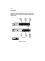
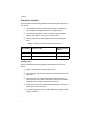
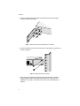
AT-FS716 AT-FS716E AT-FS724i Fast Ethernet Switches Installation Guide PN 613-10804-00 Rev F Copyright 2002 Allied Telesyn, Inc. 960 Stewart Drive Suite B, Sunnyvale CA 94086, USA All rights reserved. No part of this publication may be reproduced without prior written permission from Allied Telesyn, Inc. Ethernet is a registered trademark of Xerox Corporation. All other product names, company names, logos or other designations mentioned herein are trademarks or registered trademarks of their respective owners. Allied Telesyn, Inc. reserves the right to make changes in specifications and other information contained in this document without prior written notice. The information provided herein is subject to change without notice. In no event shall Allied Telesyn, Inc. be liable for any incidental, special, indirect, or consequential damages whatsoever, including but not limited to lost profits, arising out of or related to this manual or the information contained herein, even if Allied Telesyn, Inc. has been advised of, known, or should have known, the possibility of such damages. Electrical Safety and Emissions Compliance Statement For AT-FS716 and AT-FS716E Standards: This product meets the following standards. U.S. Federal Communications Commission Radiated Energy Note: This equipment has been tested and found to comply with the limits for a Class A digital device pursuant to Part 15 of FCC Rules. These limits are designed to provide reasonable protection against harmful interference when the equipment is operated in a commercial environment. This equipment generates, uses, and can radiate radio frequency energy and , if not installed and used in accordance with this instruction manual, may cause harmful interference to radio communications. Operation of this equipment in a residential area is likely to cause harmful interference in which case the user will be required to correct the interference at his own expense. Note: Modifications or changes not expressly approved of by the manufacturer or the FCC, can void your right to operate this equipment. Canadian Department of Communications This Class A digital apparatus meets all requirements of the Canadian InterferenceCausing Equipment Regulations. Cet appareil numérique de la classe A respecte toutes les exigences du Règlement sur le matériel brouilleur du Canada. RFI Emission EN55022 Class A ! 1 Warning: In a domestic environment this product may cause radio interference in which case the user may be required to take adequate measures. ! 2 Power to the hub must be sourced only from the adapter. (AT-FS716E) ! 3 iii Electrical Safety and Emissions Compliance Statement For AT-FS724i Standards: This product meets the following standards. U.S. Federal Communications Commission Declaration Of Conformity Manufacture Name: Manufacture Address: Allied Telesyn, Inc. 960 Stewart Drive, Suite B Sunnyvale, CA 94085 USA Manufacture Telephone: 408-730-0950 Declares that the product: Fast Ethernet Switch Model Number: AT-FS724i This product complies with FCC Part 15B, Class B Limits: This device complies with part 15 of the FCC Rules. Operation is subject to the following two conditions: (1) This device must not cause harmful interference, and (2) this device must accept any interference received, including interference that may cause undesired operation. Radiated Energy Note: This equipment has been tested and found to comply with the limits for a Class B digital device pursuant to Part 15 of FCC Rules. These limits are designed to provide reasonable protection against harmful interference in a residential installation. This equipment generates, uses and can radiate radio frequency energy and, if not installed and used in accordance with instructions, may cause harmful interference to radio or television reception, which can be determined by turning the equipment off and on. The user is encouraged to try to correct the interference by one or more of the following measures: - Reorient or relocate the receiving antenna. - Increase the separation between the equipment and the receiver. - Connect the equipment into an outlet on a circuit different from that to which the receiver is connected. - Consult the dealer or an experienced radio/TV technician for help. Changes and modifications not expressly approved by the manufacturer or registrant of this equipment can void your authority to operate this equipment under Federal Communications Commission rules. iv AT-FS716 Series and AT-FS724i Installation Guide For All Models Immunity EN55024 ! 4 Electrical Safety TUV-EN60950, UL 1950 (UL/cUL) ! 5 Important: Appendix B contains translated safety statements for installing this equipment. When you see the !, go to Appendix B for the translated safety statement in your language. Wichtig: Anhang B enthält übersetzte Sicherheitshinweise für die Installation dieses Geräts. Wenn Sie ! sehen, schlagen Sie in Anhang B den übersetzten Sicherheitshinweis in Ihrer Sprache nach. Vigtigt: Tillæg B indeholder oversatte sikkerhedsadvarsler, der vedrører installation af dette udstyr. Når De ser symbolet !, skal De slå op i tillæg B og finde de oversatte sikkerhedsadvarsler i Deres eget sprog. Belangrijk: Appendix B bevat vertaalde veiligheidsopmerkingen voor het installeren van deze apparatuur. Wanneer u de ! ziet, raadpleeg Appendix B voor vertaalde veiligheidsinstructies in uw taal. Important: L'annexe B contient les instructions de sécurité relatives à l'installation de cet équipement. Lorsque vous voyez le symbole !, reportez-vous à l'annexe B pour consulter la traduction de ces instructions dans votre langue. Tärkeää: Liite B sisältää tämän laitteen asentamiseen liittyvät käännetyt turvaohjeet. Kun näet !-symbolin, katso käännettyä turvaohjetta liitteestä B. Importante: l’Appendice B contiene avvisi di sicurezza tradotti per l’installazione di questa apparecchiatura. Il simbolo !, indica di consultare l’Appendice B per l’avviso di sicurezza nella propria lingua. Viktig: Tillegg B inneholder oversatt sikkerhetsinformasjon for installering av dette utstyret. Når du ser !, åpner du til Tillegg B for å finne den oversatte sikkerhetsinformasjonen på ønsket språk. Importante: O Anexo B contém advertências de segurança traduzidas para instalar este equipamento. Quando vir o símbolo !, leia a advertência de segurança traduzida no seu idioma no Anexo B. Importante: El Apéndice B contiene mensajes de seguridad traducidos para la instalación de este equipo. Cuando vea el símbolo !, vaya al Apéndice B para ver el mensaje de seguridad traducido a su idioma. Obs! Bilaga B innehåller översatta säkerhetsmeddelanden avseende installationen av denna utrustning. När du ser !, skall du gå till Bilaga B för att läsa det översatta säkerhetsmeddelandet på ditt språk. v Table of Contents Electrical Safety and Emissions Compliance Statement ....................iii For AT-FS716 and AT-FS716E.........................................................................iii For AT-FS724i ................................................................................................... iv For All Models..................................................................................................... v Welcome to Allied Telesyn .......................................................................... ix Where to Find Related Guides.......................................................................... ix Document Conventions ..................................................................................... ix Contacting Allied Telesyn Technical Support................................................... x Online Support ............................................................................................ x Telephone Support ...................................................................................... x E-mail Support ........................................................................................... xi Returning Products ........................................................................................... xi Management Software Updates ....................................................................... xi For Sales or Corporate Information ................................................................ xii Tell Us What You Think .................................................................................. xii Chapter 1 Overview .......................................................................................................... 1 Key Features....................................................................................................... 2 Status LEDs........................................................................................................ 3 Power Requirements .......................................................................................... 3 Internal Power Supply ................................................................................ 3 External Power Supply ............................................................................... 3 Auto MDI/MDI-X ................................................................................................ 4 Auto-negotiation ................................................................................................. 4 Network Topologies ............................................................................................ 5 Power Workgroup Topology ........................................................................ 5 Cascade Topology ........................................................................................ 6 vii Table of Contents Chapter 2 Installation ...................................................................................................... 7 Verifying the Package Contents ........................................................................ 7 Planning the Installation ................................................................................... 8 Selecting a Site ............................................................................................ 8 Reviewing Safety Guidelines ...................................................................... 9 Installing the Switch on a Table or Desktop................................................... 10 Rackmounting the Switch ................................................................................ 11 Warranty Registration ..................................................................................... 13 Chapter 3 Troubleshooting ........................................................................................... 15 Appendix A Technical Specifications ............................................................................ 17 Physical ............................................................................................................. 17 Environmental .................................................................................................. 17 Electrical Rating ............................................................................................... 18 Agency Compliance........................................................................................... 18 Pinout Assignments.......................................................................................... 19 Appendix B Translated Safety and Emission Information ....................................... 21 For AT-FS716 and AT-FS716E ........................................................................ 22 For AT-FS724i................................................................................................... 24 All Models.......................................................................................................... 25 viii Welcome to Allied Telesyn This guide contains instructions on how to install the AT-FS716, AT-FS716E, and AT-FS724i Fast Ethernet Switches. Where to Find Related Guides The Allied Telesyn web site at www.alliedtelesyn.com offers you an easy way to access the most recent documentation, software, and technical information for all of our products. For product guides, select “Support & Services” from our web site. Document Conventions This guide uses the following conventions: Note Notes provide additional information. Caution Cautions informs you that performing or omitting a specific action may result in equipment damage or loss of data. Warning Warnings informs you that performing or omitting a specific action may result in bodily injury. ix Welcome to Allied Telesyn Contacting Allied Telesyn Technical Support You can contact Allied Telesyn technical support online or by telephone or e-mail. Online Support You can request technical support online by accessing the Knowledge Base at http://kb.alliedtelesyn.com. You can use the Knowledge Base to submit questions to our technical support staff and review answers to previously asked questions. Telephone Support For technical support by phone, contact Allied Telesyn at one of the following locations: Americas United States, Canada, Mexico, Central America, South America Tel: 1 (800) 428-4835 Germany Germany, Switzerland, Austria, Eastern Europe Tel: (+49) 30-435-900-126 Asia Singapore, Taiwan, Thailand, Malaysia, Indonesia, Korea, Philippines, China, India, Hong Kong Tel: (+65) 3815-612 Italy Italy, Spain, Portugal, Greece, Turkey, Israel Tel: (+39) 02-41-30-41 Australia Tel: 1 (800) 000-880 Japan Tel: (+81) 3-3443-5640 France France, Belgium, Luxembourg, The Netherlands, Middle East, Africa Tel: (+33) 0-1-60-92-15-25 United Kingdom United Kingdom, Denmark, Norway, Sweden, Finland Tel: (+0044) 1235-442500 x AT-FS716 Series and AT-FS724i Installation Guide E-mail Support Latin America, Mexico, Puerto Rico, Caribbean, and Virgin Islands [email protected] Europe [email protected] Returning Products Products for return or repair must first be assigned a Return Materials Authorization (RMA) number. A product sent to Allied Telesyn without a RMA number will be returned to the sender at the sender’s expense. To obtain an RMA number, contact Allied Telesyn’s Technical Support at one of the following locations: North America Toll-free: 1-800-762-1664 Fax: 1-425-806-1050 Europe, Africa, and the Middle East Tel: +44-1793-501401 Fax: +44-1793-431099 Latin America, the Caribbean, and Virgin Islands Tel: international code + 425-481-3852 Fax: international code + 425-481-3895 Puerto Rico Tel: 1-800-424-5012, ext 3852 or 1-800-424-4284, ext 3852 Mexico Toll-free: 800-424-5012, ext 3852 Fax: international code + 425-481-3895 Asia and Southeast Asia Tel: +65-381-5612 Fax: +65-383-3830 Australia Toll-free: 1-800-000-880 Fax: +61-2-9438-4966 New Zealand Toll-free: 0800-45-5782 Management Software Updates New releases of management software for our managed products can be downloaded from our web site at www.alliedtelesyn.com or our FTP server at ftp.alliedtelesyn.com. To use the FTP server, enter ‘anonymous’ for the user name and your e-mail address for the password. xi Welcome to Allied Telesyn For Sales or Corporate Information You can contact Allied Telesyn for sales or corporate information at the location below: Allied Telesyn, Inc. 19800 North Creek Parkway, Suite 200 Bothell, WA 98011 Tel: 1 (425) 487-8880 Fax: 1 (425) 489-9191 Tell Us What You Think If you have any comments or suggestions on how we might improve this or other Allied Telesyn documents, please fill out the General Enquiry Form online. This form can be accessed by selecting “Contact Us” from www.alliedtelesyn.com. xii Chapter 1 Overview The AT-FS716, AT-FS716E, and AT-FS724i are Fast Ethernet switches that provide simple, cost-effective solutions for switching between 10 Mbps and 100 Mbps. The AT-FS716 and AT-FS716E switches feature 16 10/100Base-TX twisted pair ports. The AT-FS724i switch features 24 10/100Base-TX twisted pair ports. Each twisted pair port has a RJ-45 connector and a maximum operating distance of 100 meters (328 feet). These ports are capable of auto-negotiating at 10 or 100 Mbps and feature half- and full-duplex operation. The AT-FS716 and AT-FS724i feature an internal power supply and are designed for desktop or rackmount installation. The AT-FS716E features an external power supply and is designed for desktop use only. These switches are easy to install and do not require software configuration or management. Figure 1 illustrates the front panel of an AT-FS716 Series Switch. Figure 1 AT-FS716 Series Front Panel (Model AT-FS716E) Figure 2 illustrates the front panel of the AT-FS724i switch. Figure 2 AT-FS724i Front Panel 1 Overview Table 1 lists the number of ports, connector type, and maximum operating distance for each switch. Table 1 AT-FS716 Series and AT-FS724i Switches Model Number of Ports 10/100Base-TX Connector Maximum Operating Distance AT-FS716 16 RJ-45 100 m (328 ft) AT-FS716E 16 RJ-45 100 m (328 ft) AT-FS724i 24 RJ-45 100 m (328 ft) Key Features The AT-FS716 Series and AT-FS724i switches have the following key features: " LEDs for unit and port status " 16 or 24 auto-negotiating 10/100Base-TX ports " Auto MDI/MDI-X on all ports " MAC address table with a capacity of 4k addresses " Store and forward switching mode " Installs in a standard 19-inch rack (AT-FS716 and AT-FS724i only) 2 AT-FS716 Series and AT-FS724i Installation Guide Status LEDs Table 2 lists the status LEDs for the AT-FS716 Series and AT-FS724i switches. Table 2 Status LEDs LED Color Description POWER Green Power is applied to the switch. LINK/ACTIVITY Green A valid link has been established on the port. Blinking The port is transmitting data. OFF A link has not been detected on the port. Green The port is operating at 100 Mbps. OFF The port is operating at 10 Mbps. Green The port is operating in full-duplex mode. OFF The port is operating in half-duplex mode. 100M FDX (Full-duplex) Power Requirements Internal Power Supply The AT-FS716 and AT-FS724i use a universal internal switching power supply with 100 to 240 V AC, 50/60 Hz, 0.5A input rating. Allied Telesyn ships power cords with these units to the U.S., Continental Europe, and the U.K. The switches require input of 100 to 240 V AC. The AT-FS716 and AT-FS716E switches have a maximum power consumption of 8W. The AT-FS724i switch has a maximum power consumption of 15W. External Power Supply The AT-FS716E uses an external power adapter which is included with the unit. 3 Overview Auto MDI/MDI-X An RJ-45 twisted pair port on a 10 Mbps or 100 Mbps Ethernet network device can have one of two possible wiring configurations: MDI or MDI-X. The RJ-45 port on a PC, router, or bridge is typically wired as MDI, while the twisted pair port on a switch or hub is usually MDI-X. To connect two 10 Mbps or 100 Mbps network devices together that have dissimilar port wiring configurations, such as MDI to MDI-X, you use a straight-through twisted pair cable. To connect two network devices that have the same wiring configuration, such as MDI to MDI, you use a crossover cable. The AT-FS716, AT-FS716E, and AT-FS724i switches have auto MDI/MDI-X on all ports. Auto MDI/MDI-X automatically determines the configuration of the port on the end-node to which it is connected and then configures itself appropriately. For example, if a port on a switch is connected to a port on a bridge, which is typically wired as MDI, the port on the switch automatically configures itself as MDI-X. This feature allows you to use a straight-through or a crossover cable when connecting end-nodes to the switch. Auto-negotiation Auto-negotiation determines the duplex mode of the ports. The duplex mode refers to the manner in which an end-node sends and receives data on the network. Depending on its capabilities, an end-node can operate in either halfor full-duplex mode. An end-node operating in half-duplex can either send or receive data, but not both at the same time. However, an end-node operating in full-duplex can send and receive data simultaneously. The best network performance is achieved when an end-node can operate in full-duplex mode. The AT-FS716 Series and AT-FS724i switches can operate in either full- or half-duplex mode. 4 AT-FS716 Series and AT-FS724i Installation Guide Network Topologies The AT-FS716 Series and AT-FS724i switches can be used in a variety of network topologies, such as a power workgroup or cascade. Both topologies are described below. Power Workgroup Topology A power workgroup topology, shown in Figure 3, allows each end-node to directly connect to a 10/100Base-TX port on an AT-FS716 switch. This gives each end-node a dedicated 10 Mbps or 100 Mbps link. Workstations AT-FS716 Workstations Server 10 Mbps 100 Mbps Figure 3 Power Workgroup Topology 5 Overview Cascade Topology Connecting two similar networking devices together is called ‘cascading’. Figure 4 illustrates this topology where Port 24 on the AT-FS724i switch is connected to Port 8 on the AT-FS716 switch. Since Port 24 is wired as auto MDI/MDI-X, a crossover or straight-through Category 5 or better twisted pair cable can be used. Workstations AT-FS724i 100 m (328 ft) AT-FS716 Workstations 10 Mbps 100 Mbps Figure 4 Cascade Topology 6 Server Chapter 2 Installation Verifying the Package Contents Make sure the following items are included in your package. If any item is missing or damaged, contact your Allied Telesyn sales representative for assistance. ❑ One AT-FS716, AT-FS716E, or AT-FS724i Fast Ethernet Switch ❑ Four protective feet (for desktop use only) ❑ This installation guide ❑ Warranty card For AT-FS716E: ❑ External power adapter For AT-FS716 and AT-FS724i: ❑ An AC power cord ❑ Rackmounting kit 7 Installation Planning the Installation Be sure to observe the following guidelines when planning the installation of your switch. ❑ The end-nodes connected to the twisted pair port can operated at either 10 Mbps or 100 Mbps and half- or full-duplex mode. ❑ The end-node connected to a port on the switch can be a network adapter card, repeater, router, hub, or another switch. ❑ Refer to Table 3 for the cabling specifications for the twisted pair ports. Table 3 10/100Base-TX Twisted Pair Port Cabling Specifications Operating Mode Twisted Pair Cable Maximum Operating Distance 10Base-T Shielded or unshielded Category 3 or better 100 m (328 ft) 100Base-TX Shielded or unshielded Category 5 or better 100 m (328 ft) Selecting a Site Be sure to observe the following guidelines when selecting a site for your switch. 8 ❑ Select a site that is dust-free and moisture-free. ❑ Select a site that will allow you to easily access the switch’s power and data cables. ❑ The twisted pair port cabling must be kept away from sources of electrical noise, such as radios, transmitters, power lines, broadband amplifiers electrical motors, and fluorescent fixtures. ❑ Make sure the air flow around the switch and through its vents on the side and back are not restricted. ❑ Use dedicated power circuits or power conditioners to supply reliable power to the switch. AT-FS716 Series and AT-FS724i Installation Guide Reviewing Safety Guidelines Please review the following safety guidelines before you begin to install the switch. Caution Power to the hub must be sourced only from the adapter. (AT-FS716E) !3 Warning Electrical Shock Hazard: To prevent electrical shock, do not remove the cover. There are no user-serviceable parts inside. The unit contains hazardous voltages and should only be opened by a trained and qualified technician. ! 6 Warning Lightning Danger: Do not work on equipment or cables during periods of lightning activity. ! 7 Caution Pluggable Equipment: The socket outlet should be installed near the equipment and should be easily accessible. ! 8 Caution Air vents: The air vents must not be blocked on the unit and must have free access to the room ambient air for cooling. ! 9 Caution Operating Temperature This product is designed for a maximum ambient temperature of 40 degrees C. ! 10 Caution All Countries: Install product in accordance with local and National Electrical Codes. ! 11 9 Installation Installing the Switch on a Table or Desktop If you are rackmounting an AT-FS716 or AT-FS724i switch, refer to “Rackmounting the Switch” on page 11. Note The AT-FS716E switch can only be use on a table or desktop. To install the switch on a table or desktop, perform the following procedure: 1. Remove all equipment from the packaging and store the packing material in a safe place. In the event a problem occurs and you need to return the unit, please use as much of the original shipping material as possible. 2. Attach the four protective feet to the bottom of the unit. See Figure 5. Figure 5 Attaching the Rubber Feet 3. Place the switch on a flat, secure surface leaving ample space around the switch for ventilation. 4. Apply power to the switch by plugging the AC/DC power adapter into an AC power outlet, then plug the DC connector to the power receptacle located on the back of the switch. 5. Verify that the POWER LED is green. If the LED is OFF, refer to “Troubleshooting” on page 15. Note The switch performs a self-diagnostic test upon power up. This takes about 20 seconds to complete. 6. Connect the twisted pair cables to a twisted pair ports on the switch and on the end-nodes. 7. Power ON the end-nodes connected to the switch. 10 AT-FS716 Series and AT-FS724i Installation Guide 8. Check that the LINK/ACTIVITY LED for each port on the switch is green. If a LED is OFF, refer to “Troubleshooting” on page 15. The switch is now ready for use. Rackmounting the Switch The AT-FS716 and AT-FS724i switches can be used on a desktop or installed in a rack. For desktop installation, refer to “Installing the Switch on a Table or Desktop” on page 10. To install the AT-FS716 or AT-FS724i in a rack, perform the following procedure: 1. If attached, remove the four protective feet from the bottom of the switch as shown in Figure 6. Figure 6 Removing the Rubber Feet 2. Remove the data cables and power cord from the switch. 11 Installation 3. Attach the rackmounting brackets to each side of the switch using the screws provided. See Figure 7. Figure 7 Attaching the Rackmounting Brackets to the Switch 4. Secure the switch to the rack using 2 screws (not provided) for each side as shown in Figure 8. Figure 8 Installing the Switch to the Rack 5. Apply power to the switch by plugging one end of the power cord to the power receptacle and the other end to a power outlet. Verify that the POWER LED is green. If the LED is OFF, refer to “Troubleshooting” on page 15. 12 AT-FS716 Series and AT-FS724i Installation Guide Note The switch performs a self-diagnostic test upon power up. This takes about 20 seconds to complete. 6. Connect the twisted pair cables to a twisted pair ports on the switch and on the end-nodes. 7. Power ON the end-nodes connected to the switch. 8. Check that the LINK/ACTIVITY LED for each port on the switch is green. If a LED is OFF, refer to “Troubleshooting” on page 15. The switch is now ready for use. Warranty Registration When you finish installing the product, you should register you product by completing the enclosed warranty card and sending it in. 13 Chapter 3 Troubleshooting Follow the guidelines below to test and troubleshoot the installation in the event a problem occurs. If the POWER LED is OFF, do the following: " For an external power supply, check to be sure that the power adapter is securely connected to a power outlet and that the power adapter cable is securely connected to the back of the switch. " For an internal power supply, check to be sure that the power cord is securely connected to a power outlet and that the other end of the power cord is securely connected to the back of the switch. " Verify that the power outlet has power by connecting another device to it. " Try using another power adapter or power cord, depending on your model. If a LINK/ACTIVITY LED is OFF, do the following: " Check that the end-node connected to the port is powered ON and is operating properly. " Check that the twisted pair cable is securely connected to the twisted pair port on the switch and to the port on the remote end-node. " Make sure that the twisted pair cable does not exceed 100 meters (328 feet) and that you are using Category 3 or better cable for 10Base-T operation or Category 5 or better cable for 100Base-TX operation. " Verify that the end-node is operating at 10 Mbps or 100 Mbps. If you are still experiencing problems after testing and troubleshooting the installation, contact Allied Telesyn Technical Support for assistance. Refer to “Contacting Allied Telesyn Technical Support” on page x or visit our web site at www.alliedtelesyn.com for support information. 15 Appendix A Technical Specifications Physical Dimensions: WxDxH AT-FS716/AT-FS716E 330 mm x 203 mm x 44 mm (13.0 in x 8.0 in x 1.73 in) AT-FS724i 440 mm x 174 mm x 41 mm (17.32 in x 6.85 in x 1.61 in) Weight: AT-FS716 1.8 kg (4.0 lbs) AT-FS716E 2.0 kg (4.4 lbs) AT-FS724i 2.5 kg (5.5 lbs) Environmental Maximum Operating: 0° to 40° C (32° to 104° F) Maximum Storage: -25° to 70° C (-13° F to 158° F) Relative Humidity Operating: 5% to 80% (non-condensing) Relative Humidity Storage: 5% to 95% (non-condensing) Operating and Storage Altitude: Up to 3,048 meters (10,000 feet) 17 Technical Specifications Electrical Rating Internal Universal Power Supply: AT-FS716/AT-FS724i 100 - 240 V AC, 50/60 Hz, 0.5A input External Power Adapter: AT-FS716E 5 ± 5% V DC, 1.6A maximum Agency Compliance EMI/RFI: AT-FS716/AT-FS716E FCC Class A, EN55022 Class A, VCCI Class A, CISPR Class A AT-FS724i FCC Class B, EN55022 Class B, VCCI Class B, CISPR Class B Electrical Safety: TUV-EN60950, UL 1950 (UL/cUL) Immunity: EN55024 18 AT-FS716 Series and AT-FS724i Installation Guide Pinout Assignments Figure 9 shows the pin assignments of the RJ-45 connector. Pin 8 Pin 1 Figure 9 RJ-45 Connector Table 4 lists the 100Base-TX connector pins and their signals when the port is operating in either MDI or MDI-X configuration. Table 4 RJ-45 Pin Signals MDI-X (Default) Signal MDI Signal 1 RX+ 1 TX+ 2 RX- 2 TX- 3 TX+ 3 RX+ 4 - 4 - 5 - 5 - 6 TX- 6 RX- 7 - 7 - 8 - 8 - 19 Appendix B Translated Safety and Emission Information Important: This appendix contains multiple-language translations for the safety statements in this guide. Wichtig: Dieser Anhang enthält Übersetzungen der in diesem Handbuch enthaltenen Sicherheitshinweise in mehreren Sprachen. Vigtigt: Dette tillæg indeholder oversættelser i flere sprog af sikkerhedsadvarslerne i denne håndbog. Belangrijk: Deze appendix bevat vertalingen in meerdere talen van de veiligheidsopmerkingen in deze gids. Important: Cette annexe contient la traduction en plusieurs langues des instructions de sécurité figurant dans ce guide. Tärkeää: Tämä liite sisältää tässä oppaassa esiintyvät turvaohjeet usealla kielellä. Importante: questa appendice contiene traduzioni in più lingue degli avvisi di sicurezza di questa guida. Viktig: Dette tillegget inneholder oversettelser til flere språk av sikkerhetsinformasjonen i denne veiledningen. Importante: Este anexo contém traduções em vários idiomas das advertências de segurança neste guia. Importante: Este apéndice contiene traducciones en múltiples idiomas de los mensajes de seguridad incluidos en esta guía. Obs! Denna bilaga innehåller flerspråkiga översättningar av säkerhetsmeddelandena i denna handledning. 21 Translated Safety and Emission Information For AT-FS716 and AT-FS716E Standards: This product meets the following standards. U.S. Federal Communications Commission Radiated Energy Note: This equipment has been tested and found to comply with the limits for a Class A digital device pursuant to Part 15 of FCC Rules. These limits are designed to provide reasonable protection against harmful interference when the equipment is operated in a commercial environment. This equipment generates, uses, and can radiate radio frequency energy and , if not installed and used in accordance with this instruction manual, may cause harmful interference to radio communications. Operation of this equipment in a residential area is likely to cause harmful interference in which case the user will be required to correct the interference at his own expense. Note: Modifications or changes not expressly approved of by the manufacturer or the FCC, can void your right to operate this equipment. Canadian Department of Communications This Class A digital apparatus meets all requirements of the Canadian Interference-Causing Equipment Regulations. Cet appareil numérique de la classe A respecte toutes les exigences du Règlement sur le matériel brouilleur du Canada. !1 RFI Emission !2 Warning: In a domestic environment this product may cause radio interference in which case the user may be required to take adequate measures. !3 Power to the hub must be sourced only from the adapter. (AT-FS716E) !1 Hochfrequenzstörung !2 Warnung: Bei Verwendung zu Hause kann dieses Produkt Funkstörungen hervorrufen. In diesem Fall müßte der Anwender angemessene Gegenmaßnahmen ergreifen. !3 Der Buchse darf nur aus dem Adapter Strom zugeführt werden. (AT-FS716E) !1 Radiofrekvens forstyrrelsesemission !2 Advarsel: I et hjemligt miljø kunne dette produkt forårsage radio forstyrrelse. Bliver det tilfældet, påkræves brugeren muligvis at tage tilstrækkelige foranstaltninger. !3 Strømforsyningen til apparatet må udelukkende tages fra tilpasningstransformatoren. (AT-FS716E) 22 EN55022 Class A EN55022 Klasse A EN55022 Klasse A AT-FS716 Series and AT-FS724i Installation Guide !1 RFI Emissie !2 Waarschuwing: Binnenshuis kan dit product radiostoring veroorzaken, in welk geval de. !3 Stroom mag alleen via de adapter naar het apparaat toegevoerd worden. (ATFS716E) !1 Emission d’interférences radioélectriquesEN55022 Classe A !2 Mise En Garde: dans un environnement domestique, ce produit peut provoquer des interférences radioélectriques. Auquel cas, l’utilisateur devra prendre les mesures adéquates. !3 L’alimentation du concentrateur doit être uniquement fournie par l’adaptateur. (ATFS716E) !1 Radioaaltojen häirintä !2 Varoitus: Kotiolosuhteissa tämä laite voi aiheuttaa radioaaltojen häiröitä, missä tapauksessa laitteen käyttäjän on mahdollisesti ryhdyttävä tarpeellisiin toimenpiteisiin. !3 Tähtipisteeseen (hub) syötettävän virran pitää tulla ainoastaan sovittimesta. (AT-FS716E) !1 Emissione RFI (interferenza di radiofrequenza) !2 Avvertenza: in ambiente domestico questo prodotto potrebbe causare radio interferenza. In questo caso potrebbe richiedersi all’utente di prendere gli adeguati provvedimenti. !3 Questo dispositivo deve essere alimentato solo mediante l’adattatore. (AT-FS716E) !1 RFI stråling !2 Advarsel: Hvis dette produktet benyttes til privat bruk, kan produktet forårsake radioforstyrrelse. Hvis dette skjer, må brukeren ta de nødvendige forholdsregler. !3 All strømtilførsel må komme fra adapteren. (AT-FS716E) !1 Emissão de interferência de radiofrequência !2 Aviso: Num ambiente doméstico este produto pode causar interferência na radiorrecepção e, neste caso, pode ser necessário que o utente tome as medidas adequadas. !3 Use somente o adaptador fornecido para alimentação elétrica do hub. (AT-FS716E) !1 Emisión RFI !2 Advertencia: en un entorno doméstico, este producto puede causar radiointerferencias, en cuyo caso, puede requerirse del usuario que tome las medidas que sean convenientes al respecto. EN55022 Klasse A EN55022 Luokka A EN55022 Classe A EN55022 Klasse A EN55022 Classe A EN55022 Clase A 23 Translated Safety and Emission Information !3 La energía para el dispositivo central o “hub” debe provenir únicamente del adaptador. (AT-FS716E) !1 Radiostörning !2 Varning: Denna produkt kan ge upphov till radiostörningar i hemmet, vilket kan tvinga användaren till att vidtaga erforderliga åtgärder. !3 Endast anslutningsenheten får vara kraftkälla till centralen. (AT-FS716E) EN55022 Klass A For AT-FS724i Standards: This product meets the following standards. U.S. Federal Communications Commission Declaration Of Conformity Manufacture Name: Manufacture Address: Allied Telesyn, Inc. 960 Stewart Drive, Suite B Sunnyvale, CA 94085 USA Manufacture Telephone: 408-730-0950 Declares that the product: Fast Ethernet Switches Model Number: AT-FS724i This product complies with FCC Part 15B, Class B Limits: This device complies with part 15 of the FCC Rules. Operation is subject to the following two conditions: (1) This device must not cause harmful interference, and (2) this device must accept any interference received, including interference that may cause undesired operation. Radiated Energy Note: This equipment has been tested and found to comply with the limits for a Class B digital device pursuant to Part 15 of FCC Rules. These limits are designed to provide reasonable protection against harmful interference in a residential installation. This equipment generates, uses and can radiate radio frequency energy and, if not installed and used in accordance with instructions, may cause harmful interference to radio or television reception, which can be determined by turning the equipment off and on. The user is encouraged to try to correct the interference by one or more of the following measures: - Reorient or relocate the receiving antenna. - Increase the separation between the equipment and the receiver. - Connect the equipment into an outlet on a circuit different from that to which the receiver is connected. - Consult the dealer or an experienced radio/TV technician for help. Changes and modifications not expressly approved by the manufacturer or registrant of this equipment can void your authority to operate this equipment under Federal Communications Commission rules. 24 AT-FS716 Series and AT-FS724i Installation Guide All Models !4 Immunity EN55024 !5 Electrical Safety TUV-EN60950, UL 1950 (UL/cUL) Safety !6 Electrical Notices Warning: Electric Shock Hazard To prevent ELECTRIC shock, do not remove cover. No user-serviceable parts inside. This unit contains HAZARDOUS VOLTAGES and should only be opened by a trained and qualified technician. To avoid the possibility of ELECTRIC SHOCK disconnect electric power to the product before connecting or disconnecting the LAN cables. !7 Lightning Danger Danger: Do not work on equipment or cables during periods of lightning activity. Installation !8 Caution: Pluggable Equipment: The socket outlet should be installed near the equipment and should be easily accessible. Electrical—Auto Voltage Adjustment This product will automatically adjust to any voltage between the ranges shown on the label. Electrical—Type Class 1 Equipment THIS EQUIPMENT MUST BE EARTHED. Power plug must be connected to a properly wired earth ground socket outlet. An improperly wired socket outlet could place hazardous voltages on accessible metal parts. !9 Caution: Air vents must not be blocked and must have free access to the room ambient air for cooling. ! 10 Operating Temperature: This product is designed for a maximum ambient temperature of 40 degrees C. ! 11 All Countries: Install product in accordance with local and National Electrical Codes. Normen: Dieses Produkt erfüllt die Anforderungen der nachfolgenden Sicherheitsnormen. !4 Störsicherheit EN55024 !5 Elektrische Sicherheit TUV-EN60950, UL 1950 (UL/cUL) Sicherheit !6 Achtung: Gefährliche Spannung Das Gehäuse nicht öffnen. Das Gerät enthält keine vom Benutzer wartbaren Teile. Das Gerät steht unter Hochspannung und darf nur von qualifiziertem technischem Personal geöffnet werden. Vor Anschluß der LAN-Kabel, Gerät vom Netz trennen. !7 Gefahr Durch Blitzschlag Gefahr: Keine Arbeiten am Gerät oder an den Kabeln während eines Gewitters ausführen. 25 Translated Safety and Emission Information Installation !8 Steckbares Gerät: Die Anschlußbuchse sollte in der Nähe der Einrichtung angebracht werden und leicht zugänglich sein.” Automatische Spannungseinstellung Dieses Gerät stellt sich automatisch auf die auf dem Etikett aufgeführten Spannungswerte ein. Geräte Der Klasse 1 DIESE GERÄTE MÜSSEN GEERDET SEIN. Der Netzstecker darf nur mit einer vorschriftsmäßig geerdeten Steckdose verbunden werden. Ein unvorschriftsmäßiger Anschluß kann die Metallteile des Gehauses unter gefährliche elektrische Spannungen setzen. !9 Vorsicht Die Entlüftungsöffnungen dürfen nicht versperrt sein und müssen zum Kühlen freien Zugang zur Raumluft haben. ! 10 Betriebstemperatur: Dieses Produkt wurde für den Betrieb in einer Umgebungstemperatur von nicht mehr als 40° C entworfen. ! 11 Alle Länder: Installation muß örtlichen und nationalen elektrischen Vorschriften entsprechen. Standarder: Dette produkt opfylder følgende sikkerhedsstandarder. !4 Immunitet EN55024 !5 Elektrisk sikkerhed TUV-EN60950, UL 1950 (UL/cUL) Sikkerhed !6 Elektriske Forholdsregler Advarsel: RISIKO FOR ELEKTRISK STØD For at forebygge ELEKTRISK stød, undlad at åbne apparatet. Der er ingen indre dele, der kan repareres af brugeren. Denne enhed indeholder LIVSFARLIGE STRØMSPÆNDINGER og bør kun åbnes af en uddannet og kvalificeret tekniker. For at undgå risiko for ELEKTRISK STØD, afbrydes den elektriske strøm til produktet, før LAN-kablerne monteres eller afmonteres. !7 Fare Under Uvejr Fare: UNDLAD at arbejde på udstyr eller KABLER i perioder med LYNAKTIVITET. !8 Udstyr Til Stikkontakt, stikkontakten bør installeres nær ved udstyret og skal være lettilgængelig. Installation Elektrisk—Automatisk Spændingsregulering Dette apparat vil automatisk tilpasse sig enhver spænding indenfor de værdier, der er angivet på etiketten. Elektrisk—Klasse 1-Udstyr DETTE UDSTYR KRÆVER JORDFORBINDELSE. Stikket skal være forbundet med en korrekt installeret jordforbunden stikkontakt. En ukorrekt installeret stikkontakt kan sætte livsfarlig spænding til tilgængelige metaldele. !9 Advarsel: Ventilationsåbninger må ikke blokeres og skal have fri adgang til den omgivende luft i rummet for afkøling. ! 10 Betjeningstemperatur: Dette apparat er konstrueret til en omgivende temperatur på maksimum 40 grader C. 26 AT-FS716 Series and AT-FS724i Installation Guide ! 11 Alle Lande: Installation af produktet skal ske i overensstemmelse med lokal og national lovgivning for elektriske installationer. Normen: Dit product voldoet aan de volgende veiligheidsnormen. !4 Immuniteit EN55024 !5 Electrische Veiligheid TUV-EN60950, UL 1950 (UL/cUL) Veiligheid !6 Waarschuwingen Met Betrekking Tot Elektriciteit Waarschuwing: GEVAAR VOOR ELEKTRISCHE SCHOKKEN Verwijder het deksel niet, teneinde ELEKTRISCHE schokken te voorkomen. Binnenin bevinden zich geen onderdelen die door de gebruiker onderhouden kunnen worden. Dit toestel staat onder GEVAARLIJKE SPANNING en mag alleen worden geopend door een daartoe opgeleide en bevoegde technicus. Om het gevaar op ELEKTRISCHE SCHOKKEN te vermijden, moet u het toestel van de stroombron ontkoppelen alvorens de LAN-kabels te koppelen of ontkoppelen. !7 Gevaar Voor Blikseminslag Gevaar: NIET aan toestellen of KABELS WERKEN bij BLIKSEM. Installatie !8 Aan Te Sluiten Apparatuur, de contactdoos wordt in de nabijheid van de apparatuur geïnstalleerd en is gemakkelijk te bereiken.” Elektrische Toestellen Van Klasse 1 DIT TOESTEL MOET GEAARD WORDEN. De stekker moet aangesloten zijn op een juist geaarde contactdoos. Een onjuist geaarde contactdoos kan de metalen onderdelen waarmee de gebruiker eventueel in aanraking komt onder gevaarlijke spanning stellen. !9 Opgelet: De ventilatiegaten mogen niet worden gesperd en moeten de omgevingslucht ongehinderd toelaten voor afkoeling. ! 10 Bedrijfstemperatuur: De omgevingstemperatuur voor dit produkt mag niet meer bedragen dan 40 graden Celsius. ! 11 Alle Landen: het toestel installeren overeenkomstig de lokale en nationale elektrische voorschriften. Normes: ce produit est conforme aux normes de sécurité suivantes. !4 Immunité EN55024 !5 Sécurité électrique TUV-EN60950, UL 1950 (UL/cUL) Sécurité !6 Information Sur Les Risques Électriques Avertissement: DANGER D’ÉLECTROCUTION Pour éviter toute ÉLECTROCUTION, ne pas ôter le revêtement protecteur du matériel. Ce matériel ne contient aucun élément réparable par l’utilisateur. Il comprend des TENSIONS DANGEREUSES et ne doit être ouvert que par un technicien dûment qualifié. Pour éviter tout risque d’ÉLECTROCUTION, débrancher le matériel avant de connecter ou de déconnecter les câbles LAN. !7 Danger De Foudre Danger: NE PAS MANIER le matériel ou les CÂBLES lors d’activité orageuse. 27 Translated Safety and Emission Information Installation !8 Equipement Pour Branchement Electrique, la prise de sortie doit être placée près de l’équipement et facilement accessible”. Réglage De Tension Automatique Électrique Ce matériel peut s’ajuster automatiquement sur n’importe quelle tension comprise dans la plage indiquée sur l’étiquette. Équipement De Classe 1 Électrique CE MATÉRIEL DOIT ÊTRE MIS A LA TERRE. La prise de courant doit être branchée dans une prise femelle correctement mise à la terre car des tensions dangereuses risqueraient d’atteindre les pièces métalliques accessibles à l’utilisateur. !9 Attention: Ne pas bloquer les fentes d’aération, ceci empêcherait l’air ambiant de circuler librement pour le refroidissement. ! 10 Température De Fonctionnement: Ce matériel est capable de tolérer une température ambiante maximum de 40 degrés Celsius. ! 11 Pour Tous Pays: Installer le matériel conformément aux normes électriques nationales et locales. Normit: Tämä tuote on seuraavien turvallisuusnormien mukainen. !4 Kestävyys EN55024 !5 Sähköturvallisuus TUV-EN60950, UL 1950 (UL/cUL) Turvallisuus !6 Sähköön Liittyviä Huomautuksia Varoitus: SÄHKÖISKUVAARA Estääksesi SÄHKÖISKUN älä poista kantta. Sisällä ei ole käyttäjän huollettavissa olevia osia. Tämä laite sisältää VAARALLISIA JÄNNITTEITÄ ja sen voi avata vain koulutettu ja pätevä teknikko. Välttääksesi SÄHKÖISKUN mahdollisuuden katkaise sähkövirta tuotteeseen ennen kuin liität tai irrotat paikallisverkon (LAN) kaapelit. !7 Salamaniskuvaara Hengenvaara: ÄLÄ TYÖSKENTELE laitteiden tai KAAPELEIDEN KANSSA SALAMOINNIN AIKANA. Asennus !8 Pistorasiaan Kytkettävä Laite; pistorasia on asennettava laitteen lähelle ja siihen on oltava esteetön pääsy.” Sähkö—Automaattinen Jännitteensäätö Tämä tuote säätää automaattisesti mihin tahansa jännitteeseen ohjetarrassa annettujen arvojen välillä. Sähkö—Tyyppiluokan 1 Laitteet TÄMÄ LAITE TÄYTYY MAADOITTAA. Pistoke täytyy liittää kunnollisesti maadoitettuun pistorasiaan. Virheellisesti johdotettu pistorasia voi altistaa metalliosat vaarallisille jännitteille. !9 Huomautus: Ilmavaihtoreikiä ei pidä tukkia ja niillä täytyy olla vapaa yhteys ympäröivään huoneilmaan, jotta ilmanvaihto tapahtuisi. ! 10 Käyttölämpötila: Tämä tuote on suunniteltu ympäröivän ilman maksimilämpötilalle 40°C. 28 AT-FS716 Series and AT-FS724i Installation Guide ! 11 Kaikki Maat: Asenna tuote paikallisten ja kansallisten sähköturvallisuusmääräysten mukaisesti. Standard: questo prodotto soddisfa i seguenti standard di sicurezza. !4 Immunità EN55024 !5 Sicurezza elettrica TUV-EN60950, UL 1950 (UL/cUL) Norme Di Sicurezza !6 Avvertenze Elettriche Attenzione: PERICOLO DI SCOSSE ELETTRICHE Per evitare SCOSSE ELETTRICHE non asportare il coperchio. Le componenti interne non sono riparabili dall’utente. Questa unità ha TENSIONI PERICOLOSE e va aperta solamente da un tecnico specializzato e qualificato. Per evitare ogni possibilità di SCOSSE ELETTRICHE, interrompere l’alimentazione del dispositivo prima di collegare o staccare i cavi LAN. !7 Pericolo Di Fulmini Pericolo: NON LAVORARE sul dispositivo o sui CAVI durante PRECIPITAZIONI TEMPORALESCHE. Installazione !8 Apparecchiatura Collegabile, la presa va installata vicino all’apparecchio per risultare facilmente accessibile”. Elettricità—Regolazione Automatica Della Tensione Questo prodotto regolerà automaticamente la tensione ad un valore compreso nella gamma indicata sull’etichetta. Elettricità—Dispositivi Di Classe 1 QUESTO DISPOSITIVO DEVE AVERE LA MESSA A TERRA. La spina deve essere inserita in una presa di corrente specificamente dotata di messa a terra. Una presa non cablata in maniera corretta rischia di scaricare una tensione pericolosa su parti metalliche accessibili. !9 Attenzione: le prese d’aria non vanno ostruite e devono consentire il libero ricircolo dell’aria ambiente per il raffreddamento. ! 10 Temperatura Di Funzionamento: Questo prodotto è concepito per una temperatura ambientale massima di 40 gradi centigradi. ! 11 Tutti I Paesi: installare il prodotto in conformità delle vigenti normative elettriche nazionali. Sikkerhetskrav: Dette produktet oppfyller følgende sikkerhetskrav. !4 Immunitet EN55024 !5 Elektrisk sikkerhet TUV-EN60950, UL 1950 (UL/cUL) Sikkerhet !6 Elektrisitet Advarsel: FARE FOR ELEKTRISK SJOKK For å unngå ELEKTRISK sjokk, må dekslet ikke tas av. Det finnes ingen deler som brukeren kan reparere på innsiden. Denne enheten inneholder FARLIGE SPENNINGER, og må kun åpnes av en faglig kvalifisert tekniker. For å unngå ELEKTRISK SJOKK må den elektriske strømmen til produktet være avslått før LAN-kablene til- eller frakobles. 29 Translated Safety and Emission Information !7 Fare For Lynnedslag Fare: ARBEID IKKE på utstyr eller KABLER i TORDENVÆR. Installasjon !8 Utstyr For Stikkontakt. Stikkontakten skal monteres i nærheten av utstyret og skal være lett tilgjengelig.” Elektrisk—Auto Spenningstilpasning Dette produktet vil automatisk bli tilpasset hvilken som helst strømspenning i de områdene som vises på etiketten. Elektrisk—Type 1- Klasse Utstyr DETTE UTSTYRET MÅ JORDES. Strømkontakten må være tilkoplet en korrekt jordet kontakt. En kontakt som ikke er korrekt jordet kan føre til farlig spenninger i lett t ilgjengelige metalldeler. !9 Forsiktig: Lufteventilene må ikke blokkeres, og må ha fri tilgang til luft med romtemperatur for avkjøling. ! 10 Driftstemperatur: Dette produktet er konstruert for bruk i maksimum romtemperatur på 40 grader celsius. ! 11 Alle Land: Produktet må installeres i samsvar med de lokale og nasjonale elektriske koder. Padrões: Este produto satisfaz os seguintes padrões de segurança. !4 Imunidade EN55024 !5 Segurança Eléctrica TUV-EN60950, UL 1950 (UL/cUL) Segurança !6 Avisos Sobre Características Elétricas Atenção: PERIGO DE CHOQUE ELÉTRICO Para evitar CHOQUE ELÉTRICO, não retire a tampa. Não contém peças que possam ser consertadas pelo usuário. Este aparelho contém VOLTAGENS PERIGOSAS e só deve ser aberto por um técnico qualificado e treinado. Para evitar a possibilidade de CHOQUE ELÉTRICO, desconecte o aparelho da fonte de energia elétrica antes de conectar e desconectar os cabos da LAN. !7 Perigo De Choque Causado Por Raio Perigo: NÃO TRABALHE no equipamento ou nos CABOS durante períodos suscetíveis a QUEDAS DE RAIO. Instalação !8 Equipamento De Ligação, a tomada eléctrica deve estar instalada perto do equipamento e ser de fácil acesso.” Elétrico—Ajuste Automático De Voltagem Este produto ajustar-se-á automaticamente a qualquer voltagem que esteja dentro dos limites indicados no rótulo. Elétrico—Equipamentos Do Tipo Classe 1 DEVE SER FEITA LIGAÇÃO DE FIO TERRA PARA ESTE EQUIPAMENTO. O plugue de alimentação deve ser conectado a uma tomada com adequada ligação de fio terra. Tomadas sem adequada ligação de fio terra podem transmitir voltagens perigosas a peças metálicas expostas. !9 30 Cuidado: As aberturas de ventilação não devem ser bloqueadas e devem ter acesso livre ao ar ambiente para arrefecimento adequado do aparelho. AT-FS716 Series and AT-FS724i Installation Guide ! 10 Temperatura De Funcionamento: Este produto foi projetado para uma temperatura ambiente máxima de 40 graus centígrados. ! 11 Todos Os Países: Instale o produto de acordo com as normas nacionais e locais para instalações elétricas. Normas: este producto cumple con las siguientes normas de seguridad. !4 Inmunidad EN55024 !5 Seguridad eléctrica TUV-EN60950, UL 1950 (UL/cUL) Seguridad !6 Avisos Electricos Advertencia: PELIGRO DE ELECTROCHOQUE Para evitar un ELECTROCHOQUE, no quite la tapa. No hay ningún componente en el interior al cual puede prestar servicio el usuario. Esta unidad contiene VOLTAJES PELIGROSOS y sólo deberá abrirla un técnico entrenado y calificado Para evitar la posibilidad de ELECTROCHOQUE desconecte la corriente eléctrica que llega al producto antes de conectar o desconectar los cables LAN. !7 Peligro De Rayos Peligro: NO REALICE NINGUN TIPO DE TRABAJO O CONEXION en los equipos o en LOS CABLES durante TORMENTAS ELECTRICAS. Instalacion !8 Equipo Conectable, el tomacorriente se debe instalar cerca del equipo, en un lugar con acceso fácil”. Electrico—Auto-Ajuste De Tension Este producto se ajustará automáticamente a cualquier tensión entre los valores máximos y mínimos indicados en la etiqueta. Electrico—Equipo Del Tipo Clase 1 ESTE EQUIPO TIENE QUE TENER CONEXION A TIERRA. El cable tiene que conectarse a un enchufe a tierra debidamente instalado. Un enchufe que no está correctamente instalado podría ocasionar tensiones peligrosas en las partes metálicas que están expuestas. !9 Atencion: Las aberturas para ventilación no deberán bloquearse y deberán tener acceso libre al aire ambiental de la sala para su enfriamiento. ! 10 Temperatura Requerida Para La Operación: Este producto está diseñado para una temperatura ambiental máxima de 40 grados C. ! 11 Para Todos Los Países: Monte el producto de acuerdo con los Códigos Eléctricos locales y nacionales. 31 Translated Safety and Emission Information Normer: Denna produkt uppfyller följande säkerhetsnormer. !4 Immunitet EN55024 !5 Elsäkerhet TUV-EN60950, UL 1950 (UL/cUL) Säkerhet !6 Tillkännagivanden Beträffande Elektricitetsrisk: RISK FÖR ELEKTRISK STÖTFör att undvika ELEKTRISK stöt, ta ej av locket. Det finns inga delar inuti som behöver underhållas. Denna apparat är under HÖGSPÄNNING och får endast öppnas av en utbildad kvalificerad tekniker. För att undvika ELEKTRISK STÖT, koppla ifrån produktens strömanslutning innan LAN-kablarna ansluts eller kopplas ur. !7 Fara För Blixtnedslag Fara: ARBETA EJ på utrustningen eller kablarna vid ÅSKVÄDER. Installation !8 Utrustning Med Plugg. Uttaget skall installeras i utrustningens närhet och vara lättåtkomligt”. Elektriskt —automatisk Spänningsjustering Denna produkt justeras automatiskt till alla spänningar inom omfånget som indikeras på produktens märkning. Elektriskt—Typ Klass 1 Utrustning DENNA UTRUSTNING MÅSTE VARA JORDAD. Nätkabeln måste vara ansluten till ett ordentligt jordat uttag. Ett felaktigt uttag kan göra att närliggande metalldelar utsätts för högspänning. Apparaten skall anslutas till jordat uttag, när den ansluts till ett nätverk. !9 Varning: Luftventilerna får ej blockeras och måste ha fri tillgång till omgivande rumsluft för avsvalning. ! 10 Driftstemperatur: Denna produkt är konstruerad för rumstemperatur ej överstigande 40 grader Celsius. ! 11 Alla Länder: Installera produkten i enlighet med lokala och statliga bestämmelser för elektrisk utrustning. 32