1
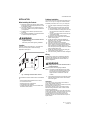
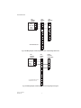
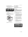
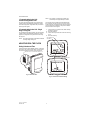
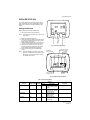
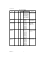
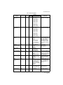
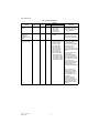
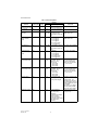
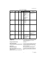
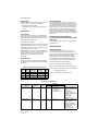
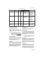
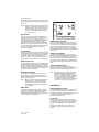
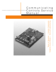
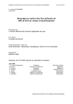
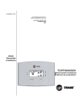
ACONT900AC43UA
COMFORT CONTROL 4 HEAT (GAS, OIL*, OR ELECTRIC)/3 COOL/HEAT PUMP
COMMUNICATING PROGRAMMABLE
3 WIRE HOOKUP
INSTALLER’S GUIDE
ALL phases of this installation must comply with NATIONAL, STATE, AND LOCAL CODES
NOTE: If this control is replacing a control that contains mercury in a sealed tube, do not place your old control in the
trash. Dispose of properly.
NOTE: Contact your local waste management authority for instructions regarding recycling and the proper disposal of
an old control.
INTRODUCTION
The ACONT900AC43UA is a communicating programmable Comfort Control that supports single-stage or multi-stage
heat/cool and heat pump applications. It is a wall mounted, low voltage (24VAC) communicating Comfort Control with
backlit LCD and a touch screen display. Room temperature is maintained by controlling the operation of heating,
cooling, heat pump, and dual fuel systems via digital, 2-way communications. The Comfort Control will communicate
with and identify all AccuLinkTM components in the system. It is easily manually configured via the user friendly Installer
Setup menu. The Comfort Control features include separate heating and cooling setpoints, selectable auto or manual
changeover, menu driven 7-day programming, adjustable filter reminders, and outdoor temperature sensing. Setup
selections and diagnostics are stored indefinitely in the Comfort Control’s nonvolatile memory eliminating the need for
battery backup.
Table 1. ACONT900AC43UA Comfort Control
Power Method
24 Vac common wire
Changeover
Automatic or Manual
selectable
System Selection
and Fan Keys*
Heat-Off-Cool-Auto
Emergency Heat
Fan Selection
On-Auto-Circ
Comments
System and Fan selection
vary, based on system type
Humidity sensor to control
dehumidification and
humidification
* See System and Fan Keys section for specific information.
Accessories
Optional
BAYSEN01ATEMPA - Outdoor Sensor - For use with communicating outdoor equipment
BAYTAM00AC00UA - Telephone Access Module (TAM)
Pub No. 11-HD04D1-2
69-2080-05
ACONT900AC43UA
PRODUCT SPECIFICATIONS
Power Source:
18-30 VAC, Class II, 50/60Hz
Storage Range:
-30°F-150°F (-34.4°C-65.6°C), 5%-90% RH non-condensing
Operating Temperature Range:
0°F-120°F (-17.8°C-37.2°C), 5%-90% RH non-condensing
System Mode:
Heat, Cool, Auto, Emergency Heat, and Off
Fan Mode:
On, Auto, and Circ
Cooling Setpoint Temperature Range:
60°F-99°F (15.5°C-37.0°C), 1°F (0.5°C) resolution
Heating Setpoint Temperature Range:
50°F-90°F (10°C-32.0°C), 1°F (0.5°C) resolution
Indoor Temperature Display Range:
40°F-99°F (4.5°C-37.0°C)
Outdoor Temperature Display Range:
-40°F-127°F (-40°C-53.0°C)
Indoor Humidity Display Range:
0%-99%, 1% resolution
Minimum Cycle Off Time Delay:
Compressor: 5 minutes
Heat: 0 minutes
This comfort control contains a Lithium battery which may contain Perchlorate material. Due to State Law in California,
the following statement is required:
Perchlorate Material - special handling may apply. See www.dtsc.ca.gov/hazardouswaste/perchlorate
Pub. No. 11-HD04D1-2
69-2080—05
2
ACONT900AC43UA
INSTALLATION
Sub-base Installation
When Installing this Product...
The Comfort Control can be mounted horizontally on the
wall or on a 2 in. by 4 in. wiring box. Position sub-base
horizontally on the wall or on a 2 in. by 4 in. wiring box.
1.
2.
3.
4.
Read these instructions carefully. Failure to follow
these instructions can damage the product or cause
a hazardous condition.
Check the ratings given in the instructions and on
the product to make sure the product is suitable for
your application.
Installer must be a trained, experienced service
technician.
After completing installation, use these instructions
to check out the product operation.
WARNING
Voltage Hazard. Can cause electrical shock or
equipment damage.
Disconnect power before beginning installation.
Location
Install the Comfort Control about 5 ft. (1.5m) above the
floor in an area with good circulation at average
temperature. See Figure 1.
1. Turn OFF all power to heating and coolingequipment.
2. If an existing Comfort Control is being replaced:
a. Remove existing Comfort Control from wall.
b. Disconnect wires from existing control, one at a
time. Be careful not to allow wires to fall back
into wall.
c. As each wire is disconnected, record wire color
and terminal marking.
d. Discard or recycle old Comfort Control.
3. Separate the Comfort Control from the subbase to
expose mounting holes.
4. Position and level the sub-base wallplate (for
appearance only). The Comfort Control functions
properly even when not level.
5. Use a pencil to mark the mounting holes.
6. Remove the sub-base from the wall and drill two
3/16 in. holes in the wall (if drywall) as marked. For
firmer material such as plaster, drill two 7/32 in.
holes. Gently tap anchors (provided) into the drilled
holes until flush with the wall.
7. Position the sub-base over the holes, pulling the
wires through the wiring opening.
8. Insert the mounting screws in the holes and tighten.
Wiring
YES
NO
All wiring must comply with local electrical codes and
ordinances. See Figures 2 and 3 wiring diagrams for
specific equipment applications. Refer to Table 2 for
terminal designations.
NO
NO
WARNING
5 FEET
[1.5 METERS]
Voltage Hazard. Can cause electrical shock or
equipment damage.
Disconnect power before beginning installation
Fig. 1. Selecting Comfort Control Location
Do not install the Comfort Control where it can be affected
by:
•
•
•
•
•
drafts or dead spots behind doors and in corners.
hot or cold air from ducts.
radiant heat from sun or appliances.
concealed pipes and chimneys.
unheated (uncooled) areas such as an outside wall
behind the Comfort Control.
NOTE: The maximum total cable length for the entire
Comfort Control communicating system is 500
feet 18 AWG. The maximum distance of any
single cable from a transformer is 250 feet
18 AWG.
1. Loosen the terminal screws on the sub-base. Insert
wires into the terminal block next to the loosened
screw. See Figure 4.
IMPORTANT
Use 18-gauge color-coded Comfort Control cable for
proper wiring. Shielded cable is not
typically required. Keep this wiring at least one foot away
from large inductive loads such as
Electronic Air Cleaners, motors, line starters, lighting
ballasts and large distribution panels. Failure to follow
these wiring practices may
introduce electrical interference (noise) which can cause
erratic system operation. All unused Comfort Control wire
to be grounded at indoor unit chassis ground only.
Shielded cable may be required if the above wiring
guidelines cannot be met. Ground the shield only to the
system chassis.
Pub. No. 11-HD04D1-2
3
69-2080—05
ACONT900AC43UA
COM.
COMFORT
CONTROL
COM.
INDOOR
UNIT
COM.
OUTDOOR
UNIT
D
D
24VAC HOT
R
R
24VAC
Common
B
B
B
Y1
Y1
Y2
Y2
O
O
BK
X2
DATA
D
W1
W2
LOW VOLTAGE WIRING TO BE NO. 18
AWG MINIMUM CONDUCTOR.
W3
G
Fig. 2. Field Wiring Diagram, Communicating Indoor Unit - Communicating Outdoor Unit
COM.
COMFORT
CONTROL
DATA
COM.
INDOOR
UNIT
SINGLE
STAGE AIR
CONDITIONER
D
D
24VAC HOT
R
R
24VAC
Common
B
B
B
Y1
Y
Y2
O
BK
W1
W2
LOW VOLTAGE WIRING TO BE NO. 18
AWG MINIMUM CONDUCTOR.
W3
G
Fig. 3. Field Wiring Diagram, Communicating Indoor Unit - Single Stage Cooling Unit
Pub. No. 11-HD04D1-2
69-2080—05
4
ACONT900AC43UA
2.
3.
4.
Securely tighten each terminal screw.
Push excess wire back in the hole.
Plug the hole in the wall with nonflammable insulation to help prevent drafts from adversely affecting
Comfort Control operation.
Table 2. Terminal Designations
Terminal
Designations
Function
D
Data
R
Power - 24 Vac (hot)
B
Power - 24 Vac (Common)
Mounting Comfort Control on Sub-base
NOTE: To remove the Comfort Control from the wall,
pull straight out.
1.
2.
3.
Align the terminal screw block with the pins on the
back of the Comfort Control.
Push the Comfort Control straight onto the wallplate. See Figure 4.
Perform installation of all other system equipment.
WALL
INITIAL POWER-UP
Power-Up Sequence
The AccuLinkTM communicating Comfort Control will
communicate and identify all AccuLinkTM components in
the system.
Discovery Mode
Discovery mode begins when AccuLinkTM communicating
Comfort Control is first installed and power is connected.
For communicating equipment, the Comfort Control
automatically configures the equipment type, number of
stages, cycle rates for each stage, and compressor stage
ratios based on the information it received during
Discovery mode.
NOTE: While in Discovery mode, the LED indicator
located in the upper right corner of the Comfort
Control will be illuminated.
NOTE: All discovered values will be saved into memory.
If a communicating device goes missing (Err 89)
or changes in value (Err 126) the error will be
broadcast to the comfort control screen. (Restoring communications will clear this error or see
ISU 0706 to reset the system configuration).
NOTE: The communicating Comfort Control can be
reset (ISU 0710) to factory default settings.
NOTE: If no equipment is connected during the AutoDiscovery process, the system mode will be
stuck at “OFF” and no equipment will run.
NOTE: To change the default/discovery settings, enter
the Installer Setup menu (see Table 4) and select
the desired item.
NOTE: Only ISU settings with an “E” will be AutoDiscovered. Manually changing an ISU setting to
an option other than “E” disables Discovery
mode for that ISU setting.
Fig. 4. Comfort Control
4.
NOTE: See Table 3 for default cycle rate settings.
Turn ON power to the heating and cooling
equipment.
Table 3. Typical Cycle Rate Settings
System
Cycles Per
Hour
Steam, Gravity
1
Hydronic Heat, Condensing Gas
Furnaces, Compressor Stages
3
Gas or Oil Forced Air, Auxiliary Heat
5
Electric Heat, Emergency Heat
9
Pub. No. 11-HD04D1-2
5
69-2080—05
ACONT900AC43UA
1. Communicating Indoor Unit Communicating Outdoor Unit
NOTE: If the system is not powered, the Real Time
Clock battery life is approximately 20 weeks.
For a fully communicating system, the communicating
Comfort Control will automatically configure the indoor
and outdoor equipment configuration and cycle rates for
each stage. See Figure 2.
The Comfort Control is designed to automatically keep
the current time and day in memory for up to ten years
under normal use once calendar is set. When the Comfort
Control is powered, the display is ready for the calendar
date to be entered. See Figure 6.
2. Communicating Indoor Unit - Single
Stage Cooling Unit
For a partially communicating system, the communicating
Comfort Control will automatically configure the indoor
equipment configuration and cycle rates for each stage.
See Figure 3.
1. Use the arrow keys to set the Year, Month and Day,
as shown in Figure 6.
2. Press the Done key.
3. Use the arrow keys to set the current time. See Figure 6.
4. Press the Done key.
SET CURRENT DAY
SET MONTH
NOTE: The outdoor equipment configuration will default
to a single stage cooling unit.
ADJUSTING REAL TIME CLOCK
MON
TUE
WED
THU
FRI
SATT
SA
SUN
OK TO PICK MULTIPLE DAYS SCREEN LOCKED
CHANGE FILTER UV LAMP HUMIDIFIER PAD
Setting Calendar and Time
Locate and remove the tab labeled “Remove” in the lower
left corner on the Comfort Control back. The tab must be
removed to activate the real-time clock. See Figure 5.
REMOVE TAB TO ACTIVATE REAL TIME CLOCK
REMOVE DURING
INSTALLATION
DONE
USE ARROWS TO SET YEAR AND TIME
MON
WED
THU
FRI
SATT
SA
SUN
REMOVE DURING
INSTALLATION
OK TO PICK MULTIPLE DAYS SCREEN LOCKED
CHANGE FILTER UV LAMP HUMIDIFIER PAD
PM
DONE
Fig. 5. Clock Activation
M22645
Fig. 6. Control Time and Date Settings
Pub. No. 11-HD04D1-2
69-2080—05
6
ACONT900AC43UA
INSTALLER SETUP (ISU)
The Comfort Control works with many different system
types. The installer can use the Installer Setup menu to
change factory settings to customize installations. See
Table 4.
WED
THU
Inside
Entering Installer Setup
FRI
SUN
Following
Schedule
OFF
COOL
Be sure the Comfort Control is powered.
SAT
AT
Set To
SYSTEM
EM HEAT
Follow these steps to enter the Installer Setup:
1.
TUE
MON
PM
DONE
CANCEL
NOTE: If necessary, press the Done key to return to the
home screen.
2.
3.
4.
5.
6.
Press and release the system key.
Press and hold the two blank keys on either side of
the center key for approximately five seconds until
screen changes. See Figure 7.
Release the two blank keys when the screen on the
Comfort Control matches the screen in Figure 8.
See Figure 8 to review how the Comfort Control
keys are used during Installer Setup. See Table 4
for the Installer Setup Numbers and Settings.
Press the Done key to exit the Installer Setupscreen.
NOTE: Manually changing an ISU setting to an option
other than “E” disables Discovery mode for that
ISU setting. If power is lost, all custom settings
are retained in the memory.
Fig. 7. Entering Installer Setup
ADVANCE TO NEXT
INSTALLER SETUP
INSTALLER
SETUP NUMBER
MON
FACTORY
SETTING
WED
THU
U
FRI
SAT
AT
SUN
DONE
O
PRESS TO EXIT
INSTALLER SETUP
CHANGE THE
FACTORY
SETTING
Fig. 8. Installer Setup Start Screen
Table 4. Installer Setup Menu
Selection
Installer Setup
Number (ISU)
Factory
Setting
Choices
Option
Description
Comments
Date (Year Upper)
0120
20
20, 21
Select the first two digits of 2001-2178 available.
current calendar year (20
for 2007)
Date (Year Lower)
0130
06
00-99
Select the last two digits of 2001-2178 available.
current calendar year (07
for the year 2007)
Date (Month)
0140
1-12
Select number that
represents current
calendar month
Date (Day)
0150
1-31
Select number that
represents current
calendar date
Pub. No. 11-HD04D1-2
7
69-2080—05
ACONT900AC43UA
Table 4. Installer Setup Menu
Selection
Installer Setup
Number (ISU)
Factory
Setting
Choices
Option
Description
Comments
Schedule Options
0160
4
0, 4
0 - Non-programmable
4 - 7 Day programmable
Restore Energy Star
Schedule
0165
0
0, 1
0 - No
No ISU or USU settings
1 - Resets the schedule to affected.
default Energy Star
System Selection
0172
E
E, 1-3
E - Auto-Discover
1 - Heat/Cool
2 - Heat Pump
3 - Heat Only (no fan)
If no equipment is
connected during the AutoDiscovery process, the
system mode will be stuck
at “off” and no equipment
will run.
Compressor Stages
0174
E
E, 0-2
E - Auto-Discover
0 - None
1 - Single Stage
2 - Two Stage/Two Step
A minimum of 1H or 1C is
required.
Heater Stages
0176
E
E, 0-3
E - Auto-Discover
0 - None
1 - Single Stage
2 - Two Stage
3 - Three stage
A minimum of 1H or 1C is
required.
Fan Operation
0180
E
E, 0, 1
E - Auto-Discover
Only seen if ISU 0172 is set
0 - Equipment controls fan to 1.
operation in heat mode
(fossil).
1 - Comfort Control
controls fan operation in
heat mode (electric).
Indoor Unit Type
0181
E
E, 0, 1
E - Auto-Discover
0 - Non-variable Speed
1 - Variable Speed
Compressor Low
Stage Airflow
0182
E
2 Stage =
50%
2 Step =
80%
E, 25, 30, E - Auto-Discover,
35, 40,
25% - 80% in 5%
45,
increments
50, 55,
60,
65, 70,
75,
80
Only shown for variable
speed indoor units.
Options may vary based on
actual system installed.
Compressor Stage 2 0183
Airflow
100%
100
Not Auto-discovered
Only shown for variable
speed indoor units.
Options may vary based on
actual system installed.
Heat Pump Warm Air 0185
Discharge
0
0, 1
0 - Disabled = 100%
1 - Enabled = 80%
Only shown for variable
speed indoor units.
50
25, 30,
35,
40, 45,
50,
55, 60,
65,
70, 75,
80,
85, 90,
95,
100
25% - 100% in 5%
increments
Only shown for variable
speed indoor units.
Continuous Fan
Airflow
0186
Pub. No. 11-HD04D1-2
69-2080—05
8
When ISU0160 is changed
from 0 (non-programmable
to 4 (programmable),
“Permanent Hold” will
display under the time icon.
This goes away when the
schedule key is hit or when
the schedule menu is
entered.
ACONT900AC43UA
Table 4. Installer Setup Menu
Selection
Installer Setup
Number (ISU)
Factory
Setting
Choices
Option
Description
Comments
Backup Heat source
(Aux heat)
0200
E
E, 0, 1
E - Auto-Discover
0 - Electric
1 - Fossil
HP only
1st Stage
Compressor Cycles
Per Hour (CPH)
0220
E
E, 2-6
E - Auto-Discover
2 - 6 is available;
(3 is recommended)
Default value is 3 CPH if
nothing is discovered.
2nd Stage
Compressor Cycles
Per Hour (CPH)
0230
E
E, 2-6
E - Auto-Discover
2 - 6 is available;
(3 is recommended)
Default value is 3 CPH if
nothing is discovered.
1st Stage Heater
Cycles Per Hour
(CPH)
0240
E
E, 2-6
E - Auto-Discover
2 - 6 is available;
(3 is recommended)
Default value is 3 CPH if
nothing is discovered.
2nd Stage Heater
Cycles Per Hour
(CPH)
0250
E
E, 2-6
E - Auto-Discover
2 - 6 is available;
(5 is recommended)
Default value is 5 CPH if
nothing is discovered.
3rd Stage Heater
Cycles Per Hour
(CPH)
0260
E
E, 2-6
E - Auto-Discover
2 - 6 is available;
(5 is recommended)
Default value is 5 CPH if
nothing is discovered.
Continuous Backlit
0280
0
0, 1
0 - Backlit not on
continuously. Comfort
Control backlight comes on
with a key press.
1 - Backlit is on
continuously. Comfort
Control backlight will come
on full brightness
with a key press and
display will dim 45
seconds after the last
keypress.
Changeover
0300
1
0, 1
0 - Manual Changeover
1 - Auto Changeover
Deadband
0310
3
3-9
3 - 3°F (2.0°C)
4 - 4°F (2.5°C)
5 - 5°F (3.0°C)
6 - 6°F (3.5°C)
7 - 7°F (4.0°C)
8 - 8°F (4.5°C)
9 - 9°F (5.0°C)
Temperature
Indication Scale
0320
0
0, 1
0 - Temperature is
displayed in °F
1 - Temperature is
displayed in °C
Daylight Savings
0330
2
0, 1, 2, 3 0 - Daylight savings is
disabled.
1 - Daylight savings is
enabled (US 1987)
2 - Daylight savings is
enabled (US 2007)
3 - Daylight savings is
enabled (Europe)
Set to 0 for areas that do
not follow daylight savings.
Outdoor Temperature 0342
Sensor
E
E, 0, 1
All communicating outdoor
units are equipped with an
ambient temperature
sensor that will be autodiscovered
E - Auto-Discover
0 - None
1 - Installed Sensor
Shown only if automatic
changeover is selected. If
ISU 0380 is set to
Integrated Temperature and
Humidity Control (ITHC),
the deadband is restricted
to a range of 5 to 9.
Pub. No. 11-HD04D1-2
9
69-2080—05
ACONT900AC43UA
Table 4. Installer Setup Menu
Selection
Installer Setup
Number (ISU)
Factory
Setting
Choices
Option
Description
Comments
Dual Fuel Heat Pump 0345
Control
1
0, 1, 2
0 - Compressor lockout
If compressor is “Failing to
only
maintain heat”, revert to aux
1 - Heat Pump Compressor heater above balance point.
lockout and failed to
maintain heat protection
2 - Heat Pump Compressor
lockout and Auxiliary Heat
lockout and Failed to
maintain heat protection in
between. To access aux
heat lockout, select option
2.
Dual Fuel Heat Pump 0346
Upstage to Furnace
Timer
60
0, 30, 45, 0 - Disabled
60, 75
30 - 30 minutes
45 - 45 minutes
60 - 60 minutes
75 - 75 minutes
System will switch to gas
furnace to satisfy call for
heat if second stage
compressor timer expires.
Heat Pump
0350
Compressor Lockout
Outdoor Temperature
0,
40 (dual
fuel)
0, 5 - 60
0 - No compressor lockout
5 - 5°F (-15.0°C)
10 - 10°F (-12.0°C)
15 - 15°F (-9.5°C)
20 - 20°F (-6.5°C)
25 - 25°F (-4.0°C)
30 - 30°F (-1.0°C)
35 - 35°F (1.5°C)
40 - 40°F (4.5°C)
45 - 45°F (7.0°C)
50 - 50°F (10.0°C)
55 - 55°F (13.0°C)
60 - 60°F (15.5°C)
System will switch to gas
furnace to satisfy call for
heat if the highest
compressor stage,
continuous-run timer
expires.
Auxiliary Heat
Lockout Outdoor
Temperature
0360
0
0, 5 - 65
0 - No auxiliary heat
lockout
5 - 5°F (-15.0°C)
10 - 10°F (-12.0°C)
15 - 15°F (-9.5°C)
20 - 20°F (-6.5°C)
25 - 25°F (-4.0°C)
30 - 30°F (-1.0°C)
35 - 35°F (1.5°C)
40 - 40°F (4.5°C)
45 - 45°F (7.0°C)
50 - 50°F (10.0°C)
55 - 55°F (13.0°C)
60 - 60°F (15.5°C)
65 - 65°F (18.5°C)
Not available for dual fuel
unless option 2 is selected
in ISU#0345. Default will be
50 in this case.
1st Stage Heater
Defrost Balance
Point
0361
0
0, 5 - 55
0 - Disabled
5 - 5°F (-15.0°C)
10 - 10°F (-12.0°C)
15 - 15°F (-9.5°C)
20 - 20°F (-6.5°C)
25 - 25°F (-4.0°C)
30 - 30°F (-1.0°C)
35 - 35°F (1.5°C)
40 - 40°F (4.5°C)
45 - 45°F (7.0°C)
50 - 50°F (10.0°C)
55 - 55°F (13.0°C)
Only shown if outdoor
temperature is available.
Pub. No. 11-HD04D1-2
69-2080—05
10
ACONT900AC43UA
Table 4. Installer Setup Menu
Selection
Installer Setup
Number (ISU)
Factory
Setting
Choices
Option
Description
Comments
2nd Stage Heater
Defrost Balance
Point
0362
40
0, 5 - 55
0 - Disabled
5 - 5°F (-15.0°C)
10 - 10°F (-12.0°C)
15 - 15°F (-9.5°C)
20 - 20°F (-6.5°C)
25 - 25°F (-4.0°C)
30 - 30°F (-1.0°C)
35 - 35°F (1.5°C)
40 - 40°F (4.5°C)
45 - 45°F (7.0°C)
50 - 50°F (10.0°C)
55 - 55°F (13.0°C)
Only shown if outdoor
temperature is available.
3rd Stage Heater
Defrost Balance
Point
0363
25
0, 5 - 55
0 - Disabled
5 - 5°F (-15.0°C)
10 - 10°F (-12.0°C)
15 - 15°F (-9.5°C)
20 - 20°F (-6.5°C)
25 - 25°F (-4.0°C)
30 - 30°F (-1.0°C)
35 - 35°F (1.5°C)
40 - 40°F (4.5°C)
45 - 45°F (7.0°C)
50 - 50°F (10.0°C)
55 - 55°F (13.0°C)
Only shown if outdoor
temperature is available.
Defrost Heater
Selection
0364
0-7
0 - None
1 - Aux1
2 - Aux2
3 - Aux3
4 - Aux1 and Aux2
5 - Aux2 and Aux3
6 - Aux1 and Aux3
7 - Aux1 and Aux2 and
Aux3
Default will be preset to the
maximum number of aux
heat stages available.
Only shown if Heater
Defrost Balance Point(s)
are disabled by selecting
“0” in ISU 0361, 0362 and/
or 0363.
For future use.
Leave at factory
default setting “E”
Discharge
0365
Temperature Sensor
E
E, 0, 1
E - Auto-Discover
0 - None
1 - Remote Sensor
Installed
Indoor Humidity
Sensor
1
0, 1, 2
0 - Disabled
1 - Internal sensor
2 - Remote sensor
Indoor Humidification 0372
Control
E, 0
E, 0, 1, 2 E - Auto-Discover
0 - Off
1 - Relative Humidity
Setpoint
2 - Dewpoint Control
Auto-Discover will discover
“0”
Dewpoint Control with Frost
Protection requires outdoor
temperature sensor
Humidifier Fan Action 0374
2
1, 2
1 - Fan turns on with
Humidifier
2 - Humidify only when
Heat is on
Only visible when ISU 0372
enabled. Fan will run for 2
minutes after humidifier
turns off.
Indoor
Dehumidification
Control
0380
1
0, 1, 4
0 - Off
1 - Integrated Temperature
and Humidity Control ITHC (RH Setpoint)
4 - American Standard
Heating & Air Conditioning
Droop (RH
Setpoint)
Deadband limited when in
Auto- Changeover Mode
and ITHC is enabled. See
“Dehumidification” on
page 19.
Comfort-RTM Delay
0381
0
0, 1, 2
0 - No Delay
1 - Comfort-RTM 15 sec
2 - Comfort-RTM 30 sec
Only shown for non-variable
speed indoor units
Dehumidification
Maximum Droop
0383
1
1, 2, 3
1 - 1°F (0.5°C)
2 - 2.0°F (1.0°C)
3 - 3°F (1.5°C)
Only shown if ITHC is
selected
0370
Pub. No. 11-HD04D1-2
11
69-2080—05
ACONT900AC43UA
Table 4. Installer Setup Menu
Selection
Installer Setup
Number (ISU)
Choices
Option
Description
Comments
100
80 - 100
80 - 80% Airflow
85 - 85% Airflow
90 - 90% Airflow
95 - 95% Airflow
100 - 100% Airflow
Only shown for variable
speed indoor units. See
Advanced Features section
for more information
American Standard
0388
Heating & Air
Conditioning
Proprietary Humidity
Control
1
0, 1
0 - Disabled
1 - Enabled
Not shown if ISU0380 is set
to 0.
See Advanced Features
section for more information
Furnace Filter 1
Change Reminder
E, 0
E, 0 - 14
E - Auto-Discover
0 - Disabled (reminder off)
1 - 10 run time days
2 - 30 run time days
3 - 60 run time days
4 - 90 run time days
5 - 120 run time days
6 - 180 run time days
7 - 270 run time days
8 - 365 run time days
9 - 30 continuous days
10 - 60 continuous days
11 - 90 continuous days
12 - 120 continuous days
13 - 180 continuous days
14 - 365 continuous days
When set to Auto-Discover
(and the discovered value is
not 0=disabled), the
Comfort Control will display
the filter timer value it
receives from the
AccuLinkTM communicating
filtering device on the More
screen.
To reset the filter timer of
the AccuLinkTM
communicating filtering
device, simply press the
More key to access the filter
timer value and then press
the Reset key. If no
AccuLinkTM communicating
filtering device has been
discovered, the autodiscovered value will default
to 0.
Dehumidification
Airflow
0387
Factory
Setting
0500
When not set to AutoDiscover (and not set to
0=disabled), the Comfort
Control will display its
internal filter timer on the
More screen.
To reset the Comfort
Control's internal timer,
simply press the More key
to access the filter timer
value and then press the
Reset key.
Pub. No. 11-HD04D1-2
69-2080—05
12
ACONT900AC43UA
Table 4. Installer Setup Menu
Selection
Furnace Filter 2
Change Reminder
Installer Setup
Number (ISU)
0501
Factory
Setting
E, 0
Choices
Option
Description
Comments
E, 0 - 14
E - Auto-Discover
0 - Disabled (reminder off)
1 - 10 run time days
2 - 30 run time days
3 - 60 run time days
4 - 90 run time days
5 - 120 run time days
6 - 180 run time days
7 - 270 run time days
8 - 365 run time days
9 - 30 continuous days
10 - 60 continuous days
11 - 90 continuous days
12 - 120 continuous days
13 - 180 continuous days
14 - 365 continuous days
When set to Auto-Discover
(and the discovered value is
not 0=disabled), the
Comfort Control will display
the filter timer value it
receives from the
AccuLinkTM communicating
filtering device on the More
screen.
To reset the filter timer of
the AccuLinkTM
communicating filtering
device, simply press the
More key to access the filter
timer value and then press
the Reset key. If no
AccuLinkTM communicating
filtering device has been
discovered, the autodiscovered value will default
to 0.
When not set to AutoDiscover (and not set to
0=disabled), the Comfort
Control will display its
internal filter timer on the
More screen.
To reset the Comfort
Control's internal timer,
simply press the More key
to access the filter timer
value and then press the
Reset key.
Humidifier Pad
Replacement
Reminder
0510
E, 0
E, 0 - 3
E - Auto-Discover
0 - Disabled
1 - 90 continuous days
(30 run time days)
2 - 180 continuous days
(60 run time days)
3 - 365 continuous days
(90 run time days)
When controlling humidifier
settings, use run time days.
Otherwise, use calendar
days.
Adaptive Intelligent
Recovery
0530
1
0, 1
0 - Conventional recovery
is activated
1 - Adaptive Intelligent
Recovery control is
activated
Adaptive Recovery starts
recovery early to reach
setpoint by start of program
period.
Number of Periods
0540
4
2, 4
2 - Two Periods available
(Wake, Sleep)
4 - Four Periods available
(Wake, Leave, Return,
Sleep)
Selection applies to all days
of the week.
Not shown if
nonprogrammable is
selected.
Heat Temperature
Range Stop
0600
90
50 - 90
Highest heating setpoint.
Temperature range (1°F
increments) of heating
setpoint.
Shown in 1/2°C
Cool Temperature
Range Stop
0610
60
60 - 99
Lowest cooling setpoint.
Temperature range (1°F
increments) of cooling
setpoint.
Shown in 1/2°C
Minimum
Noncompressor On
Time
0620
3
0 - 15
Minimum number of
minutes non-compressor
(heat) equipment is on.
Pub. No. 11-HD04D1-2
13
69-2080—05
ACONT900AC43UA
Table 4. Installer Setup Menu
Selection
Installer Setup
Number (ISU)
Factory
Setting
Choices
Option
Description
Comments
Minimum
0630
Compressor On Time
3
0 - 15
Minimum number of
minutes compressor is on.
Clock Format
0640
12
12, 24
12 - 12-hour clock format
24 - 24-hour clock format
Extended Fan On
Time Heat
0650
0
0, 30, 60, Fan operation is extended Only shown for nonvariable
90 or 120 0, 30, 60, 90 or 120
speed indoor units.
seconds after call for heat
ends.
Compressor Heat
Blower Off Delay
Profile
0651
5
0-5
Extended Fan on
time control
0660
90
0, 30, 60, Fan operation is extended Only shown for nonvariable
90 or 120 0, 30, 60, 90 or 120
speed indoor units.
seconds after call for cool
ends.
Compressor Cool
Blower Off Delay
Profile
0661
5
0-5
0 - Disabled
1 - 0.5 min @ 35%
2 - 0.5 min @ 50%
3 - 1.5 min @ 50%
4 - 0.75 min @ 100%
5 - 1.5 min @ 100%
Only shown for variable
speed indoor units.
Compressor Heat
0665
Fan On Delay Profile
0
0, 1, 5,
10, 20,
30
0 - Disabled
1 - Enabled - 50% for 1
minute (V.S. only)
5 - 5 seconds
10 - 10 seconds
20 - 20 seconds
30 - 30 seconds
For Variable Speed indoor
units: choices are 0 and 1.
For Non-variable Speed
indoor units: choices are 0,
5, 10, 20, and 30.
Compressor Cool
0667
Fan On Delay Profile
0
0, 1, 5,
10, 20,
30
0 - Disabled
1 - Enabled - 50% for 1
minute (V.S. only)
5 - 5 seconds
10 - 10 seconds
20 - 20 seconds
30 - 30 seconds
For Variable Speed indoor
units: choices are 0 and 1.
For Non-variable Speed
indoor units: choices are 0,
5, 10, 20, and 30.
Keypad Lockout
0670
0
0, 1, 2
0 - Unlocked keypad
Unlocked - all functions are
1 - Partially locked keypad available.
2 - Fully locked keypad
Partially locked - only
temperature up and down
keys and ability to enter and
modify installer setup mode
are available.
Fully locked - only ability to
enter and modify installer
setup mode are available.
Temperature Control 0680
in Heat
2
1, 2, 3
1 - Less aggressive
Applies to recovery ramp
temperature control (could and use of auxiliary heat
cause temperature
during recovery.
undershoot)
2 - Standard temperature
control in heating
3 - More aggressive
temperature control (could
cause temperature
overshoot)
0 - Disabled
1 - 0.5 min @ 35%
2 - 0.5 min @ 50%
3 - 1.5 min @ 50%
4 - 0.75 min @ 100%
5 - 1.5 min @ 100%
Pub. No. 11-HD04D1-2
69-2080—05
14
Only shown for variable
speed indoor units.
ACONT900AC43UA
Table 4. Installer Setup Menu
Selection
Installer Setup
Number (ISU)
Factory
Setting
Choices
Option
Description
2
1, 2, 3
Temperature Display 0700
Offset
0
-3, -2, -1, -3°F (-1.5°C)
0, 1, 2, 3 -2°F (-1.0°C)
-1°F (-0.5°C)
0°F (0.0°C)
1°F (0.5°C)
2°F (1.0°C)
3°F (1.5°C)
Humidity Display
Offset
0701
0
-5, -4, -3,
- 2, -1, 0,
1, 2, 3, 4,
5
-5%
-4%
-3%
-2%
-1%
0%
1%
2%
3%
4%
5%
Reset Discovered
Device
0706
0
0, 1
0 - No
1- Yes
Restore Factory
Defaults
0710
0
0, 1
0 - No Comfort Control
Only the calendar setting
reset
and time are retained.
1 - Resets all Installer
Setup options to default
values and resets schedule
to default setting
(Energy Star).
OPERATION
Using the Comfort Control
System and Fan Settings
The System default setting is Heat, unless no Heat stage
is discovered/configured. The fan default setting is Auto.
SYSTEM SETTINGS
Heat: Controls heating system.
Off: Heating and cooling are off.
Cool: Controls cooling system.
Auto: Automatically changes between heating and
cooling systems, depending on indoor temperature. (See
Installer Setup section.)
Em Heat: Compressor is locked out and auxiliary heat
1 - Less aggressive
temperature
control (could cause
temperature
undershoot)
2 - Standard temperature
control
in cooling
3 - More aggressive
temperature
control (could cause
temperature
overshoot)
Comments
Temperature Control 0690
in Cool
Applies to recovery ramp
and use of cooling stages
during recovery.
Will clear the equipment
change alert (Err 126 - see
Alert Code Addendum, form
18-HD32D2-1/69-2009) by
re-initializing Auto
Discovery
cycles to maintain temperature (Used only for heat pump
systems with backup heat.) Maximum allowable
emergency heat stages is 3.
FAN SETTINGS
Pressing the fan key selects whether the indoor fan motor
runs in the On, Automatic, or Circulation mode. The fan
setting can be programmed into the Comfort Control
schedule for each period (Wake, Leave, Return, Sleep).
On: Fan runs continuously
Auto: Fan is automatically following the fan schedule.
(See Fan Schedule section for more information.)
Circ: Circulation control will provide a variable circulation
determined by the Adaptive Intelligent Circulation (AIC)
algorithm running the fan between 20% and 60% of the
time.
Pub. No. 11-HD04D1-2
15
69-2080—05
ACONT900AC43UA
LED Indication
Alert Code Numbers
An LED indicator is located in the upper right corner of the
Comfort Control. It is only visible when lighted:
The Comfort Control can receive Alert codes from any
communicating equipment via the AccuLinkTM bus. The
Comfort Control will illuminate the Red “Service” LED and
toggle between the main screen and a screen showing
the Alert code number. When multiple Alert codes exist
simultaneously, the display will cycle through each code
(showing a maximum of the 5 most recent Alerts) and
return to the main screen. See the Alert Code Addendum
(form 18-HD32D2-1/69-2009) for a listing of all equipment
Alert codes.
• It indicates that there is an Alert.
• It indicates that the Comfort Control is in Discovery
mode.
LED Indication
FILTER INDICATION
The Comfort Control can track up to two filter timers by
total fan run time or calendar days. This feature can be
used to tell the homeowner when to replace the Furnace
filter or clean the Air Cleaner cells:
Avoid cycling compressor quickly. Observe compressor
protection period.
Select filter timer reset time:
Total Fan Run Time: the number of run time days for the
filter timer to count down from: 0, 10, 30, 60, 90, 120, 180,
270, or 365 days. (One run time day represents 24 hours
of continuous fan/system run time.)
Calendar Days: the number of days for the filter timer to
count down from: 0, 30, 60, 90, 120, 180, or 365 days. To
activate this feature, select a value other than 0
(disabled). See Owner’s Guide for more detailed
information.
Pre-programmed
Table 5 shows the Energy Star default program settings.
See Owner’s Guide for complete instructions on changing
the program.
Wake
Time
Heat
Setpoint
6:00 AM 70°F (21°C)
Cool
Setpoint
System Checkout
Installer System Test
The Installer System Test mode is used to test the
Comfort Control operation with HVAC equipment. See
Table 7. System configuration determines which tests are
available and the number of stages shown. While in
System Test mode, the minimum off time is bypassed.
The Installer Test is part of the Installer Setup options.
Enter Installer Setup screen and press the Down arrow
key for quick access to the test selection(s).
NOTE: Changing tests will turn equipment off.
NOTE: Entering Installer Setup will turn equipment off.
Table 5. Energy Star Default Program Settings
Period
Equipment Damage Hazard. Minimum
compressor off-time is bypassed during Installer
System Test.
Fan
Setting
78°F (25.5°C) Auto
NOTE: NOTE: Charge AssistTM mode not available during Installer System Tests.
NOTE: Test modes time out after 5 minutes.
Leave 8:00 AM 62°F (16.5°C) 85°F (29.5°C) Auto
Return 6:00 PM 70°F (21°C)
Sleep
78°F (25.5°C) Auto
10:00 PM 62°F (16.5°C) 82°F (28°C)
Auto
Table 6. Installer System Tests
Selection
Installer Setup
Number
Factory
Setting
Choices
Option
Comments
Description
Installer Test Cool
Test 1
0
0, 1, 2, 3
0 - Cool is off
1 - Cool stage 1
2 - Cool stage 1, 2
3 - Cool stage 1, 2, 3
Not shown if ISU 0172 is
set to 3 or if ISU0174 is
set to 0.
If Discharge Air
Temperature Sensor is
available, Press the More
key to show the
Discharge Air
Temperature value.
Installer Test Fan
Test 2
0
0, 1
0 - Fan is off
1 - Fan on
Not shown if ISU 0172 is
set to 3.
If Discharge Air
Temperature Sensor is
available, Press the More
key to show the
Discharge Air
Temperature value.
Pub. No. 11-HD04D1-2
69-2080—05
16
ACONT900AC43UA
Table 6. Installer System Tests
Selection
Installer Setup
Number
Factory
Setting
Choices
Option
Comments
Description
Installer Test Heat
Test 3
0
0, 1, 2, 3, 0 - Heat is off
4
1 - Heat stage 1
2 - Heat stage 1, 2
3 - Heat stage 1, 2, 3
4 - Heat stage 1, 2, 3, 4
Not shown if ISU 0176 is
set to 0.
If Discharge Air
Temperature Sensor is
available, Press the More
key to show the
Discharge Air
Temperature Air Value.
Installer Test
Emergency Heat
Test 4
0
0, 1, 2, 3
0 - EmHeat is off
1 - EmHeat stage 1
2 - EmHeat stage 1, 2
3 - EmHeat stage 1, 2, 3
If Discharge Air
Temperature Sensor is
available, Press the More
key to show the
Discharge Air
Temperature value.
Available only if heat
pump with auxiliary heat
is selected.
Installer Test
Humidifier
Test 5
0
0, 1
0 - Humidifier off
1 - Humidifier on
Not shown if ISU 0372 is
set to 0.
Fan will follow Hum
setting.
Installer Test
Dehumidification
Function
Test 6
0
0, 1
0 - Dehumidifier off
1 - Dehumidifier on
Not shown if ISU 0380 is
set to 0.
Fan will follow DeHum
setting.
ADVANCED FEATURES
Adjustable Continuous Air Flow
The Continuous Fan air flow is user adjustable from 25%
to 100% in 5% increments either by entering the User
Setup menu or the Installer Setup menu (see Table 4, ISU
Number 0186).
NOTE: CONTINUOUS fan mode during COOLING
operation may not be appropriate in humid climates. If the indoor air exceeds 60% relative
humidity or simply feels uncomfortably humid, it
is recommended that the fan only be used in the
AUTO mode.
Control Response Rate
A set of more/ less aggressive Proportional-Integral
control constants can be chosen to increase/decrease the
responsiveness of the temperature control performance.
Choosing a more aggressive rate may cause
overshooting. Furthermore, selecting a less aggressive
rate may result in undershooting.
Cycle Rate
Cycle rate is the selected number of system cycles per
hour at 50% load. If the cycle rate were set to 3, each ON/
OFF cycle would be 20 minutes long when operating at
50% load. The total ON and/or OFF times depends on the
actual indoor space load. A shorter cycle rate may be
desired for Heating mode to maintain tighter control to
indoor setpoint. A longer cycle rate may be desired for
Cooling mode to allow the system to remove moisture
from the air and improve indoor comfort.
Auto Changeover
When the system mode is set to Auto, the control
automatically switches between heating and cooling
modes to maintain the desired comfort level.
Setpoint Deadband
The number of degrees separating Heating and Cooling
setpoints is user adjustable from 2 to 9 degrees. When
the control is set to Auto, and the cooling setpoint is
changed to a cooler setpoint, the heating setpoint will also
change to maintain the selected deadband. The same
action occurs when the Heating setpoint is changed to a
warmer temperature.
NOTE: The deadband is restricted to a range of 5 to 9 if
ISU 0380 is set to Integrated Temperature and
Humidity Control (ITHC).
Backlit Display
When continuous backlight is disabled, the liquid crystal
display will illuminate only when a touchscreen key is
pressed to improve visibility. The backlight stays on for 45
seconds after the last touch screen key press. When
continuous backlight is enabled, the liquid crystal display
will remain illuminated continuously. The display will dim
to half brightness 45 seconds after the last touch screen
key press.
Filter Reminders
The Comfort Control can track up to two filter timers by
total fan run time or calendar days. When the preset
timer(s) has expired to remind the homeowner that it is
time to change the filter(s), “Change” then “Filter” will
automatically flash. To reset either filter timer, simply
press the More key to access the filter timer value and
then press the Reset key. Once the timer has been reset,
Pub. No. 11-HD04D1-2
17
69-2080—05
ACONT900AC43UA
the filter timer value can be viewed at any time by simply
pressing the More key until the filter timer is displayed on
the screen.
TUE
FAN
NOTE: Both the filter timers are auto discoverable ISU
settings. If no AccuLinkTM communicating filtering device has been discovered, the auto discovered value will default to 0. To enable one or
both timers, change ISU 0500 and/or ISU 0501
to a value other than 0.
Inside
Screen Locked
Locking the control’s touch screen keys can help prevent
unwanted tampering with or changing of control settings.
The Comfort Control can either be fully locked or partially
locked. Both options continuously display “Screen
Locked” on the screen. Changing ISU Number 0670 to 0
will unlock the keys and “Screen Locked” will disappear.
Installer System Tests
The built in Installer System Test mode allows the servicer
to quickly and easily test the Comfort Control’s operation
with HVAC equipment and makes diagnostic procedures
a snap. System configuration determines which tests are
available and the corresponding number of stages shown
(see Table 7, Tests 1 - 6 for details).
Default Factory Settings
The Comfort Control is shipped with a set of factory
default settings. The factory default settings can be
restored at any time using the Installer Setup menu (see
Table 4, ISU Number 0710).
NOTE: Before you perform Auto-Discovery Mode (ISU
Number 0710), is it recommended that you
record all your user settings. All user setting
choices will be reset to factory defaults in AutoDiscovery Mode.
Wait Indicator
“Wait” will be displayed when the setpoint is changed in
the direction of calling for additional system capacity or
the outdoor unit is in Charge AssistTM mode. “Wait”
indicates system time delays are being enforced, and the
control is adjusting to the new setting.
Set To
AUTO
Wait
SYSTEM
HEAT
Hold Temperature
Until
PM
Fan Selections
Pressing the Fan key selects whether the indoor fan
motor runs in the On, Automatic, or Circulation mode. In
On mode, the fan motor runs continuously. The fan
automatically follows the fan schedule in Automatic mode.
Circulation control will provide a variable circulation
determined by the Adaptive Intelligent Circulation (AIC)
algorithm running the fan between 20% and 60% of the
time. Each schedule period (Wake, Leave, Return, Sleep)
can be programmed with a specific fan setting (On,
Automatic, or Circulation).
THU
Humidity
SCHED
HOLD
CLOCK
SCREEN
MORE
CANCEL
Calibrate Indoor Temperature
This option allows calibration of the room temperature
sensor. The selected number is number of degrees, plus
or minus, which will be added to the actual temperature.
The number can range between +3 and -3 degree in 1degree increments. Factory default is 0. The adjusted
value will be used as the temperature for both display and
control action.
Calibrate Indoor Humidity
This option allows calibration of the indoor humidity
sensor. The selected number is percent relative humidity,
plus or minus, which will be added to the actual indoor
humidity. The number can range between +5% and -5% in
1% increments. Factory default is 0. The adjusted value
will be used as the humidity for both display and control
action.
Outdoor Temperature Sensor
For accuracy, the initial reading of the outdoor
temperature sensor requires five minutes to stabilize. See
the Sensor Instructions for installation information.
NOTE: If the device is using an outdoor sensor for
control and the outdoor temperature sensor
becomes unavailable, the display will show
dashes “- -” and generate an Alert. If the device
is not using an outdoor sensor for control and
the outdoor temperature sensor becomes
unavailable, no outdoor value will be displayed.
The Comfort Control will not send an Alert.
Humidification
Indoor Humidification Control
This feature attempts to control the indoor humidity to the
user’s humidification setpoint using a humidifier. The
humidification setpoint can range between 10% and 60%
in 5% increments. When enabled, the default
humidification setpoint is 50%.
Frost Control
The Frost Control requires an outdoor sensor and a
humidifier. The Comfort Control calculates the possibility
of condensation or frost forming by using the outside
temperature and inside temperature to determine the
dewpoint. When the dewpoint could cause frost or
condensation, the humidification request will not be
honored.
Pub. No. 11-HD04D1-2
69-2080—05
18
ACONT900AC43UA
The Frost Setting can be accessed by pressing the More
key until the Frost Setting is displayed on the screen. It
has a value range of 0 to 10, with 0 representing glass
with poor insulation and 10 representing glass with
perfect insulation. If the factory setting (5), results in too
much condensation or frost on the windows, lower the
setting. When the air seems too dry, raise the setting.
Special Heat Pump Features
Dehumidification
Auxiliary Heat Lockout Temperature
Integrated Temperature and Humidity Control
(ITHC)
The dehumidification control attempts to control the
indoor humidity to the user’s dehumidification setpoint by
running the compressor. The dehumidification setpoint
can be accessed by pressing the More key until the
dehumidification setpoint is displayed on the screen. The
setpoint can range between 40% and 80% in 5%
increments. When enabled, the default dehumidification
setpoint is 50%. In extremely high humidity conditions, the
Comfort Control keeps the compressor running for up to
3°F (-1.7°C) below the temperature setpoint. It does this
while trying to achieve the desired dehumidification
setpoint and balancing that with the temperature setpoint.
The maximum allowable dehumidification droop can be
selected in ISU 0383.
NOTE: American Standard Heating & Air Conditioning
Proprietary Humidity Control does not affect the
fan operation when the fan setting at the comfort
control is in Auto or Circ Modes.
When an outdoor temperature sensor has been
discovered/ enabled, none of the installed auxiliary heat
stages will turn on during heating operation above the
selected outdoor temperature. When the outdoor
temperature is less than the auxiliary heat lockout
temperature (ISU Number 0360), the Comfort Control
may cycle the indoor heat on and off to satisfy the load.
During defrost, this outdoor temperature setting is ignored
and the defrost heater balance point outdoor temperature
thresholds are used.
NOTE: For Dual Fuel applications, if the heat pump fails
to maintain heat while the outdoor temperature is
above the auxiliary lockout temperature, the furnace will be used until the setpoint is reached, at
which time heat pump operation will resume.
Compressor Heat Lockout Temperature
American Standard Heating & Air Conditioning Droop is a
feature that cycles the compressor on to improve indoor
comfort by removing moisture from the air. The Droop
cycle is activated when the indoor humidity is above the
user’s dehumidification setpoint. When this function is
active, the Comfort Control will control temperature at 1 or
2 degrees F below the cooling setpoint. The Droop cycle
is deactivated when the indoor humidity drops below the
user’s dehumidification setpoint. If the indoor humidity
sensor fails, the droop logic will always be enabled while
in cooling mode.
When an outdoor temperature sensor has been
discovered/ enabled, only the installed auxiliary heat
stages will turn on during heating operation below the
selected outdoor temperature. When the outdoor
temperature is greater than the compressor heat lockout
temperature (ISU Number 0350), the heat pump attempts
to satisfy the load.
If the heat pump can not satisfy the load and the outdoor
temperature is less than the compressor lockout
temperature (ISU Number 0350), the Comfort Control will
transition to auxiliary heat operation and will turn off the
heat pump. During defrost, this outdoor temperature
setting is ignored and the defrost heater balance point
outdoor temperature thresholds are used.
Comfort-RTM Delay
NOTE: There is a 5°F deadband between the Compressor and auxiliary heat lockout temperatures.
When the indoor humidity is above the users
dehumidification setpoint, Comfort-RTM Delay will remove
humidity from the air by implementing a blower turn-on
delay of 15 or 30 seconds to “pre-chill” the coil. ComfortRTM Delay applies to non-variable speed indoor unit types
only.
Dehumidification Airflow
During any dehumidification control option, a lower speed
fan can be activated. The settings range from 80% to
100% in 5% increments (see Table 4, Installer Setup
number 0387). The default dehumidification airflow is
100%.
American Standard Heating & Air Conditioning
Proprietary Humidity Control
When enabled, this feature will disable any blower off
delays and disable continuous fan mode when the indoor
humidity is above the dehumidification setpoint. This will
help prevent coil condensation from being evaporated
back into the air stream.
Operation in Heat Mode
When the outdoor temperature is below the compressor
lockout temperature, only the auxiliary heat operates.
When the outdoor temperature is above the auxiliary
lockout temperature, only the Compressor operates. See
Figure 9. When the outdoor temperature is between the
two temperatures, both the Compressor and auxiliary
heat operate.
OUTDOOR TEMPERATURE
American Standard Heating & Air Conditioning
Droop
COMPRESSOR ONLY
50
BOTH COMPRESSOR AND
AUXILIARY HEAT
35
AUXILIARY ONLY
AUXILIARY
LOCKOUT
TEMPERATURE
COMPRESSOR
LOCKOUT
TEMPERATURE
Fig. 9. Heat Pump Operation with Lockout
Temperatures Set.
NOTE: This feature, ISU 0388, is not shown unless
some form of dehumidification control is
selected.
Pub. No. 11-HD04D1-2
19
69-2080—05
ACONT900AC43UA
Defrost Heater Balance Point Control
When an outdoor temperature sensor has been
discovered/ enabled, a separate outdoor temperature
turn-on threshold can be set for each installed heater
stage during defrost in Installer Setup Numbers 0361 0363. If the balance point for a particular heater stage is
disabled, that heater stage will be used during every
defrost cycle independent of the outdoor temperature.
NOTE: NOTE: If the outdoor sensor is no longer reporting, all available heater stages will be used during defrost.
When an outdoor temperature sensor has not been
discovered/enabled, the stage or combination of stages to
be used during defrost can be set in Installer Setup
Number 0364.
Operation in Emergency Heat Mode
When the Comfort Control is placed in Emergency Heat
mode, the compressor and auxiliary lockout features are
turned off. In the Emergency Heat mode, the compressor
is locked out and only the auxiliary heat operates. The
Comfort Control is capable of controlling up to a maximum
of three Emergency Heat stages.
Heat Pump with Fossil Fuel Heat (Dual Fuel) and
Outdoor Temperature Sensor
In this operation, there is no external fossil fuel kit (dual
fuel kit) installed; the Comfort Control controls this
function. During the transition between Furnace and heat
pump operation, there is a minimum Comfort Control time
delay of 45 seconds between the Furnace turning off and
the heat pump turning on and 0 seconds between the
heat pump turning off and the Furnace turning on.
NOTE: If the outdoor is missing or no longer reporting,
the control algorithm will revert back to a fossil
fuel only application.
For non-communicating equipment, configure the Comfort
Control by:
1. Choose Heat Pump Application in Installer Setup
Number 0172.
2. Choose Fossil Fuel Option as the backup heat
source in Installer Setup Number 0200.
3. Outdoor Temperature Sensor for Control Option
is automatically chosen in Installer Setup Number
0342.
4. Choose appropriate Dual Fuel Heat Pump Control
in Installer Setup Number 0345.
NOTE: If the heat pump fails to maintain heat while the
outdoor temperature is above the auxiliary lockout temperature, the Furnace will be used until
the setpoint is reached, at which time heat pump
operation will resume.
5. Choose appropriate Compressor Lockout Temperature in Installer Setup Number 0350.
6. If heat pump auxiliary lockout was selected in
Installer Setup Number 0345, choose appropriate
Heat Pump Auxiliary Lockout Temperature in
Installer Setup Number 0360.
7. Choose appropriate Defrost Balance Point Temperatures in Installer Setup Numbers 0361 - 0363.
Heat Pump with Electric Auxiliary (Backup) Heat
and Outdoor Temperature Sensor
For non-communicating equipment, configure the Comfort
Control by:
1. Choose Heat Pump Application in Installer Setup
2. Choose Electric Option as the Auxiliary (Backup)
Heat Source in Installer Setup Number 0200.
3. Choose appropriate Outdoor Temperature Sensor
for Control Option in Installer Setup Number 0342.
4. If Outdoor Temperature Sensor was discovered/
enabled in Installer Setup Number 0342, choose
appropriate Compressor Lockout Temperature
in Installer Setup Number 0350.
5. If Outdoor Temperature Sensor was discovered/
enabled in Installer Setup Number 0342, choose
appropriate Heat Pump Auxiliary Lockout
Temperature in Installer Setup Number 0360.
6. If Outdoor Temperature Sensor was discovered/
enabled in Installer Setup Number 0342, choose
appropriate Defrost Balance Point Temperatures
in Installer Setup Numbers 0361 - 0363.
TROUBLESHOOTING GUIDE
Refer to Table 8 for troubleshooting information.
Pub. No. 11-HD04D1-2
69-2080—05
20
ACONT900AC43UA
Table 7. Troubleshooting Information
Symptom
Possible Cause
Action
Red service LED is illuminated
and the display alternates
between Home screen and Alert
Code screen.
Alert Code present
Refer to the Alert Code Addendum (form
18-HD32D2-1/69-2009).
Display will not come on.
1. Blown fuse or tripped circuit
breaker.
2. Indoor unit power switch OFF.
3. Indoor unit blower
compartment door or panel loose
or not properly installed.
4. Wire broken/shorted; or R and
D or B and D are reversed.
1. Replace fuse or reset breaker.
2. Turn power switch to ON.
3. Replace door panel in proper position
to engage safety interlock or door switch
on furnace.
4. Check R, B, D wiring.
Indoor temperature display is
incorrect.
Temperature display needs
calibration.
Calibrate Sensor - ISU 0700
Indoor humidity display is
incorrect.
Indoor humidity display needs
calibration.
Calibrate Sensor - ISU 0701
Outdoor temperature display
shows “--” or the outdoor
temperature is not displayed.
1. Outdoor temperature sensor
open, shorted, not reporting, or
not installed.
2. Outdoor sensor field wiring
open or shorted.
1. Replace/Install outdoor sensor.
2. Check/repair outdoor sensor field
wiring.
Indoor temperature display shows Indoor temperature sensor open Replace control.
“--”.
or shorted.
Temperature setting will not
change (e.g. Cannot increase
heating setpoint or reduce cooling
setpoint).
1. Upper and/or lower
temperature limits were reached.
2. Keys are fully locked. “Screen
Locked” is displayed on LCD.
1. Check the temperature setpoints:
Heating limits (ISU 0600) are 40°F - 90°F
(4.4°C - 32.2°C).
Cooling limits (ISU 0610) are 60°F - 99°F
(15.5°C - 32.2°C).
2. Unlock keypad - ISU 0670.
Room temperature overshoots
when the Heat/ Cool setting is
changed more than 2 degrees.
1. Oversized heating/cooling
equipment under current
conditions. Control cannot
respond fast enough to prevent
overshooting.
2. Improper location of comfort
control.
1. Set Control Response rate to
“Aggressive” - ISU 0680, 0690
2. Select a location that prevents the
Comfort Control from being directly
exposed to air currents from supply
registers.
Heating will not come on.
1. System Mode not set to Heat.
2. Minimum off time delay being
enforced.
3. Loose connection to control or
system.
4. Heating system may need
service.
1. Set Mode to heat and raise the
setpoint above room temperature.
2. If heating does not come on within 5
minutes, checking heating equipment.
3. Check/repair connections.
4. Repair system.
Cooing will not come on.
1. System Mode not set to Cool.
2. Minimum off time delay being
enforced.
3. Loose connection to control or
system.
4. Cooling system may need
service.
1. Set Mode to cool and lower the
setpoint above room temperature.
2. If cooling does not come on within 15
minutes, checking cooling equipment.
3. Check/repair connections.
4. Repair system.
Heat ON or Cool ON is displayed, 1. The heating equipment turns
but no warm air or cool air is
on the fan when the furnace has
coming from the registers.
warmed up.
2. Heating or cooling equipment
is not operating.
1. Wait one minute after Heat ON is
displayed and then check the registers.
2. Check Heating and/or Cooling
equipment.
Control does not respond to
keypad screen presses.
1. Keys are fully locked. “Screen 1. Unlock keypad - ISU 0670.
Locked” is displayed on LCD.
2. Replace control.
2. Keypad failure.
Fan does not operate properly in
heat or cool mode.
1. Heating or cooling equipment
inoperative.
1. Repair system.
Pub. No. 11-HD04D1-2
21
69-2080—05
ACONT900AC43UA
Table 7. Troubleshooting Information
Symptom
Fan runs all of the time.
Possible Cause
Action
1. Fan mode is set to ON continuous.
2. Fan scheduled to run
continuously.
3. Indoor equipment may need
service.
1. Set fan mode to AUTO or CIRC.
2. Reprogram fan schedule, if desired.
3. Check Indoor equipment.
Fan is set to “On” but not running. 1. American Standard Heating & Verify that the Dehumidification setpoint
Air Conditioning Proprietary
is below the actual indoor humidity. See
Humidity Control.
“American Standard Heating & Air
Conditioning Proprietary Humidity
Control” on page 19 for additional
information.
Cooling cycles too fast or too slow The location of the control and/or Verify/adjust cycle rates - ISU 0220,
(narrow or wide temperature
the size of the cooling system
0230.
swing).
may be influencing the cycle rate.
Heating cycle too fast or too slow The location of the control and/or Verify/adjust cycle rates - ISU 0240,
(narrow or wide temperature
the size of the heating system
0250, 0260.
swing).
may be influencing the cycle rate.
Only Furnace heat; no heat pump 1. Outdoor temperature sensor is
heating in Dual Fuel mode.
missing or no longer reporting.
2. Outdoor temperature is below
the Compressor Lockout
Temperature setting.
Cannot change system mode to
Heat or Cool mode.
1. Comfort Control not configured 1. Check/verify System Selection - ISU
properly.
0172.
No equipment is running and can Equipment was not connected
not change the mode from “OFF”. during Auto-Discovery mode.
Pub. No. 11-HD04D1-2
69-2080—05
1. Check/ repair outdoor sensor field
wiring.
2. Lower the Compressor Lockout
Temperature setting, if desired.
22
1. Check/verify wiring connection and
cycle power to components.
2. Cycle Power - System will Re-initiate
Auto-Discover.
ACONT900AC43UA
Pub. No. 11-HD04D1-2
23
69-2080—05
ACONT900AC43UA
® U.S. Registered Trademark
© 2008 American Standard Heating & Air Conditioning
All Rights Reserved
Pub. No. 11-HD04D1-2
69-2080—05 M.S. Rev. 11-08
American Standard Heating & Air Conditioning
Troup Highway
Tyler, TX 75711-9010