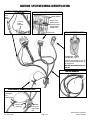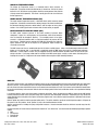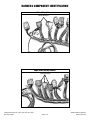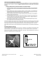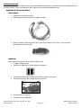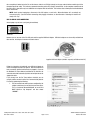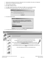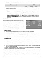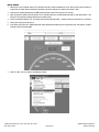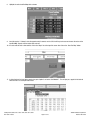
1
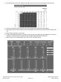
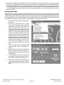
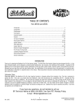
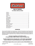
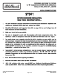
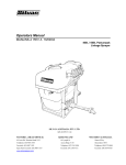
PRO-TUNER EFI SYSTEM QUICK START GUIDE
PART #3670, #3690, #3671, #3691, #3672, #3692, #3673, #3693
System #3670 Shown
Edelbrock Corporation • 2700 California St. • Torrance, CA 90503
Tech-Line: 1-800-416-8628
E-Mail: [email protected]
NOTICE
Please refer to the complete
user’s guide located on the
installation CD for a more in
depth explanation of tuning,
installation and functions of the
Victor and Super Victor Pro-Tuner
System.
Catalog #3670, 3690, 3671, 3691, 3672, 3692, 3673, 3693
Rev. 10/07 - DC/mc
©2007 Edelbrock Corporation
Brochure #63-3670
INTRODUCTION
“Total Engine Management”
That’s the slogan for Edelbrock’s Pro-Tuner EFI Systems, powered by MotoTron Electronic Control Units (ECU).
Pro-Tuner EFI Systems include everything needed to convert any engine to electronic fuel injection; with user programmable features and full ignition
control as well as fuel delivery.
Two performance levels are available. Victor Systems include a MotoTron ECM for semi-sequential injection, while Super Victor Systems feature fully
sequential operation and individual cylinder adjustment of spark and fuel for complete optimization, plus a software upgradeable MotoTron PCM with
advanced features and expandability for exciting future options. Through your laptop computer, all critical aspects of engine tuning are adjustable to
suit your application. The simplified user interface allows a tuner to dial-in the behavior of the state of the art control strategies running within the
ruggedized Engine Control Module (ECM).
The proprietary MotoTron ECU is extremely durable. It’s completely sealed making it waterproof and ideal for not only competition vehicles but for
marine as well. Once up and running, Edelbrock’s Pro-Tuner EFI software offers easy-to-use, yet sophisticated tuning control with user-friendly pull
down menus and screens.
Available separately, Edelbrock offers a Pro USB key which allows access to enhanced tuning parameters for more experienced tuners. A basic USB
key is included with the Victor kit. A Pro USB key is included with the Super Victor kit.
Before reading this manual and installing your new system, it is important to understand that your Edelbrock EFI system is more than fuel injection, it
is an Engine Management System. In addition to controlling the fueling of your engine, the system will also be controlling ignition, idle airflow,
monitoring sensor operation, and running other optional actuator outputs.
While every effort is made to simplify the installation and calibration process, the most important tool is the knowledge and experience of the person
tuning the engine. Just as with carbureted engines, the tuner must know the fueling and ignition limits of the specific engine he or she is calibrating
to avoid engine damage and provide the best reliability and drivability possible. In addition to reading this manual there are many other sources of
engine management theory, as well as experienced tuners and Edelbrock experts available to assist with questions that you may have. It is highly
recommended that the tuner educate themselves as much as possible in the area of electronic engine control and calibration theory and technique.
The help file in the software has much more detailed information.
If you run into problems, you may contact our EFI Technical Hotline at 800-416-8628 from 7:00am to 5:00pm PST Monday through Friday. You may
also contact us by email at: [email protected]
Catalog #3670, 3690, 3671, 3691, 3672, 3692, 3673, 3693
Rev. 10/07 - DC/mc
©2007 Edelbrock Corporation
Brochure #63-3670
BEFORE BEGINNING INSTALLATION
PLEASE study these instructions carefully before beginning this installation. Most installations can be accomplished with common tools and
procedures. However, you should be familiar with and comfortable working on your vehicle. If you do not feel comfortable performing this installation,
it is recommended to have the installation completed by a qualified mechanic. If you have any questions, please call our Technical Hotline at:
1-800-416-8628, 7:00 am - 5:00 pm, Pacific Standard Time, Monday through Friday or e-mail us at [email protected].
IMPORTANT NOTE: Proper installation is the responsibility of the installer. Improper installation
will void your warranty and may result in poor performance and engine or vehicle damage.
TABLE OF CONTENTS
TOOLS AND EQUIPMENT . . . . . . . . . . . . . . . . . . . . . . . . . . . . . . . . . . . . . . . . . . . . . . . . . . . . . . . . . . . . . . . . . . . .2
HARDWARE AND PARTS RECOMMENDED . . . . . . . . . . . . . . . . . . . . . . . . . . . . . . . . . . . . . . . . . . . . . . . . . . . . . . .2
SYSTEM INSTALLATION . . . . . . . . . . . . . . . . . . . . . . . . . . . . . . . . . . . . . . . . . . . . . . . . . . . . . . . . . . . . . . . . . . . . . . . . . . . 3
Distributor . . . . . . . . . . . . . . . . . . . . . . . . . . . . . . . . . . . . . . . . . . . . . . . . . . . . . . . . . . . . . . . . . . . . . . . . . . . . . . . . . 3
Installation Procedure . . . . . . . . . . . . . . . . . . . . . . . . . . . . . . . . . . . . . . . . . . . . . . . . . . . . . . . . . . . . . . . . . . . . . . . 3
IGNITION SYSTEM WIRING IDENTIFICATION . . . . . . . . . . . . . . . . . . . . . . . . . . . . . . . . . . . . . . . . . . . . . . . . . . . . . . . . . 4
Rotor Phasing . . . . . . . . . . . . . . . . . . . . . . . . . . . . . . . . . . . . . . . . . . . . . . . . . . . . . . . . . . . . . . . . . . . . . . . . . . . . . 5
Connecting the MSD 6A Type CDI Ignition . . . . . . . . . . . . . . . . . . . . . . . . . . . . . . . . . . . . . . . . . . . . . . . . . . . . . . . . .5
Fuel System Requirements . . . . . . . . . . . . . . . . . . . . . . . . . . . . . . . . . . . . . . . . . . . . . . . . . . . . . . . . . . . . . . . . . . . 5
Fuel Pump . . . . . . . . . . . . . . . . . . . . . . . . . . . . . . . . . . . . . . . . . . . . . . . . . . . . . . . . . . . . . . . . . . . . . . . . . . . . . . . 5
Fuel Pressure Regulator . . . . . . . . . . . . . . . . . . . . . . . . . . . . . . . . . . . . . . . . . . . . . . . . . . . . . . . . . . . . . . . . . . . . . .5
Injectors and Fuel Rails . . . . . . . . . . . . . . . . . . . . . . . . . . . . . . . . . . . . . . . . . . . . . . . . . . . . . . . . . . . . . . . . . . . . . 6
Sensors and Actuators . . . . . . . . . . . . . . . . . . . . . . . . . . . . . . . . . . . . . . . . . . . . . . . . . . . . . . . . . . . . . . . . . . . . . . 6
Idle Air Control Valve (IAC) . . . . . . . . . . . . . . . . . . . . . . . . . . . . . . . . . . . . . . . . . . . . . . . . . . . . . . . . . . . . . . . . . . . 6
Throttle Position Sensor (TPS) . . . . . . . . . . . . . . . . . . . . . . . . . . . . . . . . . . . . . . . . . . . . . . . . . . . . . . . . . . . . . . . . . 6
Oxygen Sensor . . . . . . . . . . . . . . . . . . . . . . . . . . . . . . . . . . . . . . . . . . . . . . . . . . . . . . . . . . . . . . . . . . . . . . . . . . . . 6
Charge Air Temperature Sensor . . . . . . . . . . . . . . . . . . . . . . . . . . . . . . . . . . . . . . . . . . . . . . . . . . . . . . . . . . . . . . . . 7
Engine Coolant Temperature Sensor (ECT) . . . . . . . . . . . . . . . . . . . . . . . . . . . . . . . . . . . . . . . . . . . . . . . . . . . . . . . 7
Manifold Absolute Pressure Sensor (MAP) . . . . . . . . . . . . . . . . . . . . . . . . . . . . . . . . . . . . . . . . . . . . . . . . . . . . . . . 7
Main Wiring Harness and Engine Wiring . . . . . . . . . . . . . . . . . . . . . . . . . . . . . . . . . . . . . . . . . . . . . . . . . . . . . . . . . 7
HARNESS COMPONENT IDENTIFICATION . . . . . . . . . . . . . . . . . . . . . . . . . . . . . . . . . . . . . . . . . . . . . . . . . . . . . . . . . . . . . 8
Installing ECU and Connecting to Main Harness . . . . . . . . . . . . . . . . . . . . . . . . . . . . . . . . . . . . . . . . . . . . . . . . . . . 9
Malfunction Indicator Light (MIL) . . . . . . . . . . . . . . . . . . . . . . . . . . . . . . . . . . . . . . . . . . . . . . . . . . . . . . . . . . . . . . 9
SOFTWARE INSTALLATION . . . . . . . . . . . . . . . . . . . . . . . . . . . . . . . . . . . . . . . . . . . . . . . . . . . . . . . . . . . . . . . . . . . . . . . .10
Connecting the Laptop to the Vehicle . . . . . . . . . . . . . . . . . . . . . . . . . . . . . . . . . . . . . . . . . . . . . . . . . . . . . . . . 10
USB to Serial Converters . . . . . . . . . . . . . . . . . . . . . . . . . . . . . . . . . . . . . . . . . . . . . . . . . . . . . . . . . . . . . . . . . . . 11
CONTROL SYSTEM TUNING STRATEGIES . . . . . . . . . . . . . . . . . . . . . . . . . . . . . . . . . . . . . . . . . . . . . . . . . . . . . . . . . . . 15
INITIAL CALIBRATION SETUP . . . . . . . . . . . . . . . . . . . . . . . . . . . . . . . . . . . . . . . . . . . . . . . . . . . . . . . . . . . . . . . . . . . . . 16
Setup Wizard . . . . . . . . . . . . . . . . . . . . . . . . . . . . . . . . . . . . . . . . . . . . . . . . . . . . . . . . . . . . . . . . . . . . . . . . . . . . . . 16
TPS Set Points . . . . . . . . . . . . . . . . . . . . . . . . . . . . . . . . . . . . . . . . . . . . . . . . . . . . . . . . . . . . . . . . . . . . . . . . . . . . . 18
Pre-Start Checklist . . . . . . . . . . . . . . . . . . . . . . . . . . . . . . . . . . . . . . . . . . . . . . . . . . . . . . . . . . . . . . . . . . . . . . . . . 19
Initial Startup . . . . . . . . . . . . . . . . . . . . . . . . . . . . . . . . . . . . . . . . . . . . . . . . . . . . . . . . . . . . . . . . . . . . . . . . . . . . . 20
Varifying Ignition Timing . . . . . . . . . . . . . . . . . . . . . . . . . . . . . . . . . . . . . . . . . . . . . . . . . . . . . . . . . . . . . . . . . . . . 23
EDELBROCK PRO-TUNER EFI KIT CONTENTS . . . . . . . . . . . . . . . . . . . . . . . . . . . . . . . . . . . . . . . . . . . . . . . . . . . . . . . 24
Catalog #3670, 3690, 3671, 3691, 3672, 3692, 3673, 3693
Rev. 10/07 - DC/mc
Page 1 of 25
©2007 Edelbrock Corporation
Brochure #63-3670
TOOLS AND EQUIPMENT
Use the following checklist for items needed.
Box and Open End Wrenches
Socket Set
Distributor Wrench
Pliers (Channel Locks and Hose Clamp)
Screwdrivers (Regular and Phillips)
Torque Wrench
Hammer
Gasket Scraper or Putty Knife
Timing Light
Vacuum Gauge
Rags
Water Bucket
Drill and Drill Bits
Tubing Wrenches
Tubing Cutter
Wire Strippers
Solderless Terminal Crimpers
Selection of Solderless Terminals
HARDWARE AND PARTS RECOMMENDED
Gaskets - Edelbrock, OEM, or Equivalent
Pipe Plugs, if Needed
5/16” Steel Tubing (Approximate Equal Length to Fuel Pickup Line in Tank)
Edelbrock Gasgacinch #9300
Loctite 598 OEM High Temperature Silicone Gasket (O2 Sensor Compatible)
Radiator Coolant
Edelbrock Teflon Thread Tape #9275
Intake Gasket (See Catalog or Consult Dealer Representative for Part Number)
Manifold Bolt Kit (See Catalog or Consult Dealer Representative for Part Number)
Throttle, Cruise Control & Transmission Kick-Down Mounting Bracket #8036 (If Necessary See General Catalog)
Wiring Diagram For Your Vehicle
Catalog #3670, 3690, 3671, 3691, 3672, 3692, 3673, 3693
Rev. 10/07 - DC/mc
Page 2 of 25
©2007 Edelbrock Corporation
Brochure #63-3670
SYSTEM INSTALLATION
Installing the Edelbrock Pro-Tuner EFI system in a vehicle is a straight-forward procedure that is not difficult; particularly if you have experience
replacing intake manifolds and basic automotive electrical knowledge. During this stage, it is helpful to consult a factory service manual (if available)
or a Haynes Repair Manual for your vehicle (www.haynes.com) as well as the Edelbrock Pro-Tuner Users Guide. An electronic copy of the guide is
included with the software.
For proper system function and warranty coverage, it is very important that all installation instructions be followed during installation and operation.
Read this Quick Start Guide completely before beginning the installation. If you have questions about a particular step, refer to the Edelbrock Pro-Tuner
Users Guide for more detail. If you do not understand a procedure, contact the Edelbrock Technical Hotline at 800-416-8628. If you do not have the
necessary skill or tools to perform any of the operations, consult a professional dealer/installer for assistance.
NOTE: It is recommended to take your vehicle’s battery to a local auto parts store to test for proper voltage and amperage capacity. When reinstalling the battery, make sure to thoroughly clean the battery terminals as well as the vehicle battery cable ends before connecting.
DISTRIBUTOR
The Pro-Tuner Distributor with Cam-Sync is designed for use with our Edelbrock Pro-Tuner EFI systems. The distributor includes an
adjustable hold down collar on some applications (to accommodate various deck heights and custom intake manifolds), a large distributor
cap, and the mechanical advance is locked out. It is equipped with a steel distributor drive gear. The Pro-Tuner distributor also features a
Magnetic Crank Pickup and uses a Hall-Effect Cam-Sync Pickup with LED indicator for the Camshaft Sensor. The Cam Sync has a 12” lead
and a 3-prong Weatherpak connector. The crank trigger has an 8” lead and 2-prong Weatherpak connector.
IMPORTANT INSTALLATION NOTES
• Make sure that the distributor seats down completely and has fully engaged the oil pump drive. You may
need to rotate the oil pump shaft to ensure it is engaged properly. Failure to achieve proper engagement
will cause engine damage.
•
DO NOT use a Solid-Core type spark plug wire set, such as copper core, etc. You must use a suppression type spark plug wire.
Failure to use the correct wires will cause electrical interference with the Engine Control Module.
•
When installing the distributor, make sure to disconnect the vehicle’s battery BEFORE beginning the installation.
•
This distributor has a steel drive gear, check with your camshaft manufacturer for cam compatibility with this gear.
•
If the drive gear is ever replaced, you must use a MSD #8531 distributor drive gear due to the .500” diameter drive shaft.
•
A white dot is located on the distributor base beneath the location for the #1 cylinder.
INSTALLATION PROCEDURE
1.
Loosen the adjustable slip collar where necessary. Install the Distributor into the engine without the gasket installed, make
sure the oil pump shaft is fully engaged, and slide the slip the collar down to sit against the manifold. Tighten the collar and
remove the distributor. Tighten the set screws on the collar and install the gasket. NOTE: Adjustable slip collar used on
small & big block Chevy kits only.
2.
Rotate the crankshaft in the direction of normal rotation until cylinder #1 is coming up on the compression stroke. Stop turning
when the crankshaft is at 22° BTDC.
3.
Liberally apply assembly lubricant to the drive gear and install the distributor (using the supplied gasket) so that the rotor
comes to rest pointing at what will be the #1 terminal on
the cap. Position the cap such that #1 is in the location
Firewall
shown on the drawing below. You may need to remove
and reinsert the distributor a few times to get the
Front of
alignment correct. Make sure that the distributor seats
Install Clips
Engine
down completely and has fully engaged the oil pump
Parallel to
drive. You may need to rotate the oil pump shaft to ensure
Firewall
it is engaged properly.
4.
Lift the rotor by hand to make sure that there is adequate
end play. Lack of end play indicates that the rotor shaft is
bottomed out on the oil pump shaft. If there is no end play
readjust the slip collar as mentioned in Step 1 above.
5.
Align the distributor cap clips parallel with the firewall.
The Hall Effect Sensor should be pointing toward the
forward drivers side of the engine.
6.
Cyl. #1 (White Dot)
Tighten the distributor hold down clamp.
Catalog #3670, 3690, 3671, 3691, 3672, 3692, 3673, 3693
Rev. 10/07 - DC/mc
Page 3 of 25
©2007 Edelbrock Corporation
Brochure #63-3670
IGNITION SYSTEM WIRING IDENTIFICATION
IGNITION SYSTEM WIRING DETAIL
Distributor
2 Pin
Crank
Sensor
Connector
IGNITION AMPLIFIER CONNECTION DETAIL
Ignition Amplifier
Plug the 4 pin
ignition harness
connector into the
ignition amplifier
(supplied) here.
3 Pin Cam
Sensor
Connector
Ignition Harness
COIL CONNECTIONS DETAIL
Red/Yellow Wire - Coil (+)
Black/White Wire - Coil (-)
Secure the ring terminals to the coil
with the hardware supplied from the
coil manufacturer.
NOTE: Coil not included in the ProTuner kit
IGNITION HARNESS
MAIN HARNESS CONNECTIONS DETAIL
Connect all
ground lugs to
clean
bellhousing bolt
Connect coil
power here
Plug ignition
harness into
main harness
here
Catalog #3670, 3690, 3671, 3691, 3672, 3692, 3673, 3693
Rev. 10/07 - DC/mc
Page 4 of 25
©2007 Edelbrock Corporation
Brochure #63-3670
ROTOR PHASING
Firewall
Rotor phasing is defined as the alignment between the rotor tip and
the distributor cap terminal when the spark occurs. This position can
be very important to your engine’s performance. If the alignment is
incorrect, the spark will jump to the next closest terminal, or another
ground resulting in a misfire and loss of power. In applications with
extreme cylinder pressures, such as with nitrous or forced induction,
correct rotor phasing increases in importance. More voltage is
required to jump the plug gap and if rotor phasing is off, the spark is
more apt to find an easier path to ground rather than the correct cap
terminal. This may result in severe engine damage.
CONNECTING THE MSD 6A TYPE CDI IGNITION
Rotor
Front of
Engine
Cyl. #1
FROM PRO-TUNER IGNITION HARNESS
COIL (+) RED/YELLOW WIRE
FROM PRO-TUNER IGNITION HARNESS
COIL (-) BLACK/WHITE WIRE
MAGNETIC PICKUP
(NOT USED)
TO BATTERY
TO BATTERY
HEAVY RED
HEAVY BLACK
D
RE
ITE
WH
E
NG
A
OR
K
AC
BL
FUEL SYSTEM REQUIREMENTS
FUEL PUMP
The Edelbrock Pro-Tuner system requires a high-pressure electric fuel pump which is
capable of pumping 50 or more psi (depending upon the pump). The pump relay will
prime the system on key-up and shut down the pump if it does not receive an enginerun signal from the ECU, as in the case of a stall. This safety precaution is necessary
when using a high-pressure fuel system. It is very important that the fuel flow capacity
of the EFI pump exceed your peak demand by 20-25% to avoid engine damage due to
loss of pressure. Consult your Edelbrock dealer for assistance in pump selection. A
high pressure/high volume EFI fuel filter should be mounted between the engine
compartment and the fuel pump to allow fuel to be pushed through the filter rather
than drawn through. Consult your Edelbrock dealer for assistance in filter selection.
Use the mounting instructions for the pump and filter that you are using.
FUEL PRESSURE REGULATOR
Fuel pressure is as important as fuel volume, particularly in fuel injection. The
Fuel Pump Wiring Harness
Edelbrock Pro-Tuner system requires that the fuel pressure regulator maintains a
constant pressure at the injectors. It is recommended that Manifold Absolute Pressure references the regulator diaphragm to
maintain constant pressure across all 8 injectors, regardless of fluctuating manifold pressure (vacuum) level. The fuel that is not
injected is returned to the fuel tank via the return fuel line. Recommended pressure settings vary with application. Consult your
Edelbrock dealer for pressure recommendations.
Recommended Fuel Pump and Fuel Pressure Regulator Kits:
Part #35943 (Up to 600 HP)
Kit includes Fuel Pump #3594 and Fuel Pressure Regulator #1728
Part #17903 (Up to 800 HP)
Kit includes Fuel Pump #1790 and Fuel Pressure Regulator #1729
Part #17943 (Up to 1500 HP)
Kit includes Fuel Pump #1794 and Fuel Pressure Regulator #1729
Catalog #3670, 3690, 3671, 3691, 3672, 3692, 3673, 3693
Rev. 10/07 - DC/mc
Page 5 of 25
©2007 Edelbrock Corporation
Brochure #63-3670
INJECTORS AND FUEL RAILS
INSTALLATION
1. Fasten fuel rail stands (if applicable) to manifold per Edelbrock instructions; making sure the stands are parallel with
the injector bosses in the manifold.
2. Lightly lubricate the O-rings at the top and bottom of each injector using the supplied Russell Precision Hose and
Fitting Assembly Lube.
3. Install the top of each injector into the fuel rail; carefully inserting the injector to avoid pinching or damaging the
sealing o-ring. Orient the injector so that the connector is facing outward (The outside of the rail has the Edelbrock
logo on the side).
4. Carefully insert the rail w/injectors into the manifold, insuring that each injector enters the manifold straight and
lower O-rings do not get pinched or damaged.
NOTE: If O-rings are damaged even slightly, they MUST be replaced before pressurizing the system!
5. Align mounting holes in rail with the rail mounts.
6. Install with hardware provided.
7. Remember to attach the coated injector harness J-clamps to each rail mount. Orient the clip so that it is above the
mounting hole.
SENSORS AND ACTUATORS
The Pro-Tuner system has been designed to work with specific components. They are
easily selectable through the Pro Tuner Setup Wizard. Substitution with other
components may cause running problems or system damage.
IDLE AIR CONTROL VALVE (IAC) (PWM Type)
The Idle Air Control (IAC) valve is controlled by the ECM and controls airflow to
help maintain a set point speed at idle. The behavior of the valve can be
calibrated for your combination through the laptop Pro Tuner software. The IAC
comes installed on the Edelbrock throttle body.
THROTTLE POSITION SENSOR (TPS)
The Throttle Position Sensor (TPS) comes installed on your throttle body and
should require no mechanical adjustment. Scaling of the sensor is accomplished
through the Setup Wizard. When replacing the sensor, the TPS scaling of the min
and max values should be recalibrated through the Setup Wizard. It is also a
good idea to reset the TPS Set Points in the Setup Wizard or from
the TOOLS menu a second time after the engine idle is tuned in and
your final throttle blade setting is reached (See “TPS Set Points”.
Remember to cycle switched power after adjusting TPS Set Points).
OXYGEN SENSORS (O2)
The exhaust gas oxygen content is measured by the oxygen sensor. The sensor signals the ECU, which compensates when the
air/fuel mixture is either rich or lean. If the exhaust system is already configured for an oxygen sensor port, simply replace the
existing sensor with the Edelbrock sensor. Route and secure wires and connectors away from exhaust heat. Allow enough slack
for exhaust pipe movement.
If your exhaust system does not have an O2 port, you will need to weld the included threaded bung into the exhaust pipe. It is
extremely important to make sure that your exhaust system is free of leaks. Leaks could cause false readings
that may damage the engine. It is recommended that the O2 sensor installation be performed by a
professional muffler shop.
INSTALLATION
1. Double check header gaskets, replacing if necessary.
2. Drill a 5/8-inch hole in the driver-side exhaust pipe, 6” to 13” behind the collector flange.
NOTE: Before drilling, make sure the O2 sensor will be mounted at a slight downward angle in the top half
of the exhaust pipe and within reach of the harness connector. Check to insure adequate clearance for the
sensor, taking into consideration engine movement.
3. Fit the provided fitting into the hole in the exhaust pipe and weld into place.
4. Once it has been welded into place, clean the threads in the center of the fitting.
5. Thread the O2 sensor into the fitting. A high-heat anti-seize compound has been applied to the sensor threads.
NOTE: The O2 sensor has 18mm x 1.25 spark plug threads.
6. After the main harness is installed (See Main Wiring Harness and Engine Wiring Section), attach the O2 sensor to the
main system harness driver side connector.
NOTE: UNLEADED FUEL MUST BE USED ONCE THE O2 SENSOR HAS BEEN INSTALLED.
Catalog #3670, 3690, 3671, 3691, 3672, 3692, 3673, 3693
Rev. 10/07 - DC/mc
Page 6 of 25
©2007 Edelbrock Corporation
Brochure #63-3670
CHARGE AIR TEMPERATURE SENSOR
The Charge Air Temperature sensor is a thermistor device which measures air
temperature. This sensor must be installed into the air cleaner base. Drill the air cleaner
base with a 3/4” drill, deburr any sharp edges, install the sensor grommet, then slide the
air temp sensor into the grommet. This sensor is usually placed in the rear of the base
for best appearance.
ENGINE COOLANT TEMPERATURE SENSOR (ECT)
The engine coolant temperature sensor is a thermistor device which measures coolant
temperature. It should be screwed into the coolant passage of the intake manifold near
the thermostat housing to measure coolant before it exits the engine on its way to the
radiator. It has 3/8 NPT pipe thread and comes with a thread sealant pre-applied.
MANIFOLD ABSOLUTE PRESSURE SENSOR (MAP)
The MAP sensor measures pressure in the intake manifold (A pressure below
atmospheric is typical in a running engine, and is sometimes called vacuum when the
value is referenced to atmospheric baseline.). The manifold pressure is low (highvacuum) in a light load condition; while in a high load condition, the pressure will rise
(low vacuum). Manifold pressure provides the ECM with information that helps the
system determine the load on the engine so the appropriate output changes are
calculated and executed.
The MAP sensor must have an unobstructed signal to the intake manifold plenum: either at the throttle body below the throttle
blades, or in the plenum itself. A small bracket is supplied to mount the MAP sensor to one of the 4 throttle body hold down
bolts/studs. A small length of vacuum line (not supplied) should be installed between the MAP sensor and the vacuum port
reference location. If an orange, rubber boot is installed on the MAP sensor nipple, carefully cut and remove this boot prior to
installing the vacuum line. Replacement of sensor should be done using the original mounting hardware.
MAIN WIRING HARNESS AND ENGINE WIRING
To install the system harness, you should first layout the harness in your vehicle to determine the best layout and routing for your application.
Of primary concern, is the mounting location of the Engine Control Module (ECM/PCM), relays, interface connectors, and system fusing.
Once all sensors have been installed, the harness can be routed and connected to each lead. Each harness lead is labelled for identification.
Be sure the vehicle battery is disconnected. Route & retain the wiring to protect it from heat and vibration and for a clean, professional looking
installation.
It is important that the system has reliable power and ground connections. Attach the ground wires AND fuel pump harness AND ignition
harness ground black leads to the same point using clean & paint-free bell housing bolt connection. Alternatively, you may connect the
system grounds to the same point on the engine as the battery negative lead. Insure that the engine/transmission is grounded to the chassis
and body as well.
Connect ignition key-switch lead to the operator ignition switch. The switch should be capable of maintaining uninterrupted +12V power to
the system in the “On” position, “Crank” position, as well as the transition between the two.
Connect remaining wires, including fuel pump and ignition harnesses. Unused connectors should be coiled and secured away from dirt,
debris, and heat.
Unused connectors will include harness leads labeled “Knock Drive” and “Knock Pass” and could include the following depending on options
chosen:
1) MAF
2. Fuel Pressure
3. Pass Side O2
4. Oil Pressure
Catalog #3670, 3690, 3671, 3691, 3672, 3692, 3673, 3693
Rev. 10/07 - DC/mc
Page 7 of 25
©2007 Edelbrock Corporation
Brochure #63-3670
HARNESS COMPONENT IDENTIFICATION
Victor (48 pin) Harness
2 Main Connectors
Super Victor (80 pin) Harness
3 Main Connectors
Catalog #3670, 3690, 3671, 3691, 3672, 3692, 3673, 3693
Rev. 10/07 - DC/mc
Page 8 of 25
©2007 Edelbrock Corporation
Brochure #63-3670
INSTALLING ECU AND CONNECTING TO MAIN HARNESS
You may choose to mount the ECM inside the passenger compartment similar to OEM practice. However, the ruggedized ECM also
gives you the option of mounting it under hood. Improper installation may cause system failure and void your
warranty.
To mount the ECM and relays correctly, the following rules should be followed:
1.
Keep ECM, components, and wiring as far away from heat and exhaust parts as possible. You may need to install
heat shields over certain areas in the engine compartment to prevent excessive heat from reaching the electrical
components.
2.
Mount the ECM and relays using only the grommets, bushings, and washers provided. Use the Edelbrock ECU
mounting bracket for proper mounting and flexible orientation. These parts are specially engineered to insure proper
isolation of the ECM. Locate the fuse pack so that it can be accessed conveniently.
3.
Insure that the ECM case does not touch or rub against anything, particularly metal or wiring. The case MUST be
isolated from grounds and voltage sources.
4.
Do not mount hardware in such a manner as to cause stress on the harness. Do not pull, stretch, or kink wires and
connectors. Minimize effect of engine torque movement on short sections of harness. Improper installation can
cause intermittent wire or connector failure or total loss of connection.
5.
Route harnessing to avoid sharp edges, heat, and wear points. Clamp harnessing with approved clamps and clips.
Do ALL installation work with the vehicle battery disconnected.
The Pro-Tuner (Victor/Super Victor) controller mounts using specially designed bushing’s and isolation grommets. When installing
the mounts, first install the rubber grommets into the 3 mounting holes. Insert the bushing from the BACKSIDE of the grommet.
Finally, mount to the desired surface using the provided retaining washer on the top side of the grommet and a ¼-20 screw.
When the ECU and main harness are securely installed, plug the main connector into the ECU. The connectors will only plug in one
way.
MALFUNCTION INDICATOR LIGHT (MIL)
To mount the Malfunction Indicator Light (MIL), drill a 5/16” hole in a suitable panel. Insert the MIL into the hole with the orange
light facing toward you. Locate the MIL circuit in the engine harness. It is near the expansion connector. See picture below.
Connect one wire of the MIL to the orange/white wire labeled “MIL” in the harness. Connect the other MIL wire to a key-on 12V
power source. Polarity does not matter. See diagram below.
MIL Light
Catalog #3670, 3690, 3671, 3691, 3672, 3692, 3673, 3693
Rev. 10/07 - DC/mc
Page 9 of 25
©2007 Edelbrock Corporation
Brochure #63-3670
SOFTWARE INSTALLATION
Installation and configuration of the software is much like any other Windows based application. It uses Install Shield and will prompt you for choices
during the installation. In most cases choosing the “NEXT” button will give you the recommended default values.
CONNECTING THE LAPTOP TO THE VEHICLE
ITEMS REQUIRED
1.
Laptop with Pro-Tuner software installed
2.
Computer Connection cable and USB to Serial Adapter (if needed).
3.
USB Key (or “dongle”) The key will be either a “Base” system key or an optional, “Pro” level key. The key is required
for the software to connect to the ECU.
CONNECTION
Before hooking up the laptop, be sure the following conditions are met:
1.
The laptop is booted and ready.
2.
The USB Key is plugged into an available USB slot on the computer.
3.
The Computer Connection cable is plugged into the Interface connector on the harness.
4.
The Computer Connection cable is plugged into the PC’s serial port.
5.
The vehicle’s battery is connected.
6.
The ignition key is in the ON position.
Catalog #3670, 3690, 3671, 3691, 3672, 3692, 3673, 3693
Rev. 10/07 - DC/mc
Page 10 of 25
©2007 Edelbrock Corporation
Brochure #63-3670
Once everything is hooked up to the PC and the harness, look for an LED light (steady) on the gray colored interface module (part of the
Computer Connection cable). This indicates a powered connection and the PC is ready to communicate. As the computer communicates to
the vehicle ECU, a few cables may have additional red and green LEDs that will blink. This indicates data is flowing back and forth between
the PC and the ECU.
NOTE: Avoid repeated unplugging or disconnect of the USB adapter or serial cable. Microsoft windows will occasionally not
reconnect properly. If you have trouble reconnecting after plugging in hardware, or after hibernation. Rebooting the machine will
usually clear it up.
USB TO SERIAL PORT CONVERTERS
Some laptops may not have a serial port (pictured below)
Serial Port
However, you can use one of the PC’s USB ports and the supplied USB/Serial Adapter. USB/Serial adapters are also readily available from
other sources, including local consumer electronics stores.
USB Ports
Supplied USB/Serial Adapter (Available separately as Edelbrock #91147)
Follow the instructions included with your USB/Serial Adapter to
install and configure the device for your PC. Once the software has
been successfully installed and the device is plugged in, if you run
the Edelbrock Pro Tuner software installation for the first time, the
connection wizard will automatically detect and configure to use the
appropriate device.
If you already have the Pro Tuner software installed, you can
manually add the new device to the list of communication ports for
Pro Tuner by performing the following:
1.
First, we need to know which port was configured by the
adapter manufacturer for use with that particular device.
This is a function of Microsoft Windows, so we will first
RIGHT CLICK on “My Computer” and then choose
“MANAGE”.
Catalog #3670, 3690, 3671, 3691, 3672, 3692, 3673, 3693
Rev. 10/07 - DC/mc
Page 11 of 25
©2007 Edelbrock Corporation
Brochure #63-3670
2.
Now choose “DEVICE MANAGER” to get a list of the installed and active devices for your PC.
3.
Click on the “PORTS” icon to expand the list of communications ports. You should see your USB to Serial Adapter in the list of
ports. Often times, it will be assigned to COM4 if you do not have a lot of other devices attached to your PC. In this example,
we see the “Prolific USB-to-Serial Com Port” on COM8.
Catalog #3670, 3690, 3671, 3691, 3672, 3692, 3673, 3693
Rev. 10/07 - DC/mc
Page 12 of 25
©2007 Edelbrock Corporation
Brochure #63-3670
4.
Make a note of the COM port assignment and close the Computer Management window.
5.
Now, RIGHT click on the MotoServer icon (the satellite dish) in the System Tray (lower right hand corner of your screen).
6.
A menu will appear for MotoServer. Choose “Ports...”
7.
A list of the configured ports will appear. To add the port that the USB/Serial Adapter manufacturer’s software configured, click
on “Edit Names”.
8.
When you click “Edit Names”, you will be presented a choice of pre configured ports. If the COM port you need is in the list,
simply select that port and then click “OK”. If it does not exist, click “Add” to add your new port.
9.
When you click “Add”, you will be asked what kind of port is to be added. Select “Serial” and the click “Next”.
Catalog #3670, 3690, 3671, 3691, 3672, 3692, 3673, 3693
Rev. 10/07 - DC/mc
Page 13 of 25
©2007 Edelbrock Corporation
Brochure #63-3670
10. Type your new COM port name and number in the space provided. In this example, we will call the port “COM8” and put “8”
in the port text box, since that is what we noted earlier in the Device Manager.
11. The new port name then appears in the Port Name listing. Make sure the new port is selected and then choose “OK” (or
“Apply” if you have more ports to add).
12. You will now be back at the Port Configuration window. Choose “Add “ and then select the Type and Location with the drop
down lists. Be sure the Access Level is set to “4”.
Catalog #3670, 3690, 3671, 3691, 3672, 3692, 3673, 3693
Rev. 10/07 - DC/mc
Page 14 of 25
©2007 Edelbrock Corporation
Brochure #63-3670
13. Click “OK” and you will see the new Port Added to the Ports List.
14. From now on, the Pro Tuner system will check to see if communications cable is plugged into any of the devices listed in the
Ports Configuration List every time you start the program. You can add a large number of pre configured ports as necessary
to support your needs.
15. Click “OK” to complete the set up.
CONTROL SYSTEM TUNING STRATEGIES
Your Edelbrock system is capable of three different fuel/timing control strategies. Modeled Speed Density uses sensor inputs along with a Volumetric
Efficiency (VE) table to estimate the air flow through the engine. The air fuel target table is used in conjunction with this calculated air flow to control
the injector pulsewidth. The MAP-N strategy uses a base fuel map that varies as a function of engine speed and manifold pressure. The desired base
injector pulsewidth is displayed in the table. The Alpha-N strategy uses a base fuel map that varies with engine speed and throttle position. The desired
base injector pulsewidth is displayed in the table. The Alpha-N strategy works very well for engines with very large camshafts that exhibit very low
idle vacuum. The table below summarizes the advantages and disadvantages to each control strategy:
Advantages
Disadvantages
Modeled Speed Density
MAP-N
Alpha-N
• If set up properly, does not require tuning of
temperature based trim tables.
• Direct measurement of engine load (assuming the VE table is accurately defined).
• Can adjust for changes in engine tuning
requirements if used with optional mass air
flow sensor (MAF).
• If set up properly, will be more consistent as
operating conditions change.
• Relatively quick and easy to tune
• Base fuel map in units of injector pulsewidth.
• Very common tuning method, used in many
available aftermarket EFI systems.
• Works well for and is easy to tune for
boosted applications.
• Easy to modify calibration if larger injectors
are installed.
• Works well for large overlap camshafts. Not
affected by low idle vacuum signal.
• Relatively quick and easy to tune.
• Base fuel map in units of injector pulsewidth.
• Easy to modify calibration if larger injectors
are installed.
• Requires accurate volumetric efficiency
table.
• Fuel control units more difficult to understand.
• Mass Air Flow (MAF) sensor (if used) can be
difficult to retrofit to older engines.
• Does not work well with large overlap camshafts due to low idle vacuum signal.
• Requires temperature based trim tables.
• Indirect measurement of engine load.
• Calibration could be inconsistent if trim
tables are not properly tuned.
• Idle mixture affected by closed throttle TPS
voltage drift.
• Requires temperature based trim tables.
• Indirect measurement of engine load.
• Does not work well with idle air control (IAC)
motors.
• Calibration could be inconsistent if trim
tables are not properly tuned.
The following section “Initial Calibration Setup”, will describe the steps necessary to set up a calibration for the first time. You must choose a tuning
strategy when setting up your calibration for the first time. Use the table above to decide which strategy best suits your tuning needs.
Catalog #3670, 3690, 3671, 3691, 3672, 3692, 3673, 3693
Rev. 10/07 - DC/mc
Page 15 of 25
©2007 Edelbrock Corporation
Brochure #63-3670
INITIAL CALIBRATION SETUP
In this chapter we will walk you through setting up the Edelbrock Pro-Tuner software for the first time.
SETUP WIZARD
The Setup Wizard functionality is used to make fundamental changes to your system configuration, such as new fuel injectors, different
distributor or coil, new sensors, etc. It is also a good way to setup a “bare” system for first time use.
1.
To start the wizard, go to TOOLS in the top menu of the main application.
2.
Choose “Setup Wizard”
3.
The wizard will start up and you will be asked to make various choices to set up your system. If this is NOT your first time into
the wizard, it will go to the last thing you successfully executed (a BOOKMARK). At that point, you can go directly to the area
that you need to make changes to without stepping through the rest of the wizard.
4.
Assuming this is the first time through, you will first see this screen:
5.
Click NEXT and watch the status bar at the bottom of the screen as it establishes a new connection to the ECU and configures
it for programming.
6.
The next screen will show you the Engine Setup wizard to help you configure your basic engine parameters:
Catalog #3670, 3690, 3671, 3691, 3672, 3692, 3673, 3693
Rev. 10/07 - DC/mc
Page 16 of 25
©2007 Edelbrock Corporation
Brochure #63-3670
7.
Choose your basic engine type and then enter it’s displacement in cubic inches (default) or liters (chosen via the drop down)
8.
Choose the type of crank trigger you are using in your kit
9.
Select your fueling control method
10. Click “SAVE” to commit your changes.
11. The “FINISH” button will then replace the “NEXT” button. Click “FINISH” if you are satisfied with your choices.
12. The ECU will now be reprogrammed with your “base” system setup. Please click OK to continue.
13. The wizard will prepare the ECU:
14. The wizard will then program the ECU. Please wait for it to finish completely:
Catalog #3670, 3690, 3671, 3691, 3672, 3692, 3673, 3693
Rev. 10/07 - DC/mc
Page 17 of 25
©2007 Edelbrock Corporation
Brochure #63-3670
15. When programming is completed, you will be presented with the next wizard section to configure/choose your sensors. The
WELCOME section will show a CHECK MARK to show that it has been completed:
16. Continue to progress through the various section and choices, using the NEXT buttons and FINISH buttons (as they are
presented) to configure your system.
17. Once you have finished all the sections, the wizard will save your changes/choices and reprogram the ECU a final time before
exiting.
NOTE (For users who select the MAP-N Tuning Strategy from the Wizard setup ONLY): Once the Wizard
programming steps are completed, you must load the supplied MAP-N calibration file into your ECU. To do this, go
to the file menu and select “Load Calibration From Disk”. Navigate to the installed calibrations folder located at
“/Program Files/Edelbrock/EFI/ECUFiles/Cals”. The MAP-N calibration file for kit #3670 is identified as
“EDEL07E1EB_V004XDC_MAPN.hcal”. The MAP-N calibration file for kit #3690 is identified as
“EDEL07P1EB_V004XDC_MAPN.hcal”. Choose the appropriate calibration for your kit to load the calibration
into your ECU.
TPS SET POINTS
This tool is accessed via the “TOOLS” Menu and selecting “TPS Set Points”.
This tool is used to ensure the Throttle Position Sensor (TPS) is correctly
adjusted for the system “Baseline”. It changes the voltage value of the
sensor into a percentage for easy reference during calibration. The system
needs an accurate measure of the throttle position to determine the throttle
blade angle for VE calculations and scaling the TPS range.
To adjust the set points, first ensure that the throttle linkage is correctly
adjusted. There should be no tension at the idle position, with throttle
position closed and AGAINST THE THROTTLE STOP SCREW, and no binding or
obstructions with the throttle at Wide Open Throttle (WOT).
MINIMUM SET POINT
1.
Make sure the throttle is fully closed and there is not linkage binding or excess throttle stop adjustment.
2.
You should see an A/D count in the Current TPS Reading somewhere in the range of 150-250 A/D counts.
3.
IF YOU DO NOT SEE 150-250 counts, carefully check for mechanical binding or jammed throttle blades. If there is no
mechanical binding or jamming, then adjust the THROTTLE STOP SCREW until you see a value of about 200 A/D counts (as a
starting point).
4.
Once you are satisfied the reading is stabilized in the 150-250 A/D range, click the “Set Min” button to lock in the value.
MAXIMUM SET POINT
1.
Be sure to remove any obstructions to Wide Open Throttle, such as floor mats, binding linkage, transmission kick down cable
too tight, etc.
2.
Floor the throttle (allowing the throttle blades to fully open). Visually check that the blades are fully open and the linkage is not
binding.
3.
The reading now should be 875- 950 counts with the linkage correctly adjusted (throttle blades fully open) .
4.
Once you are satisfied that the reading is within the accepted range, click the “Set Max “ button WHILE HOLDING THE
THROTTLE AT THE WIDE OPEN POSITION!.
This will “lock” the set values into the ECU. Next, you will need to set your throttle blade properly for your chosen idle speed.
Remember to cycle switched power (ignition key) after changes are made.
Turn key switch to “On” or “Run” position. The fuel pump will turn on and run for approximately 4 seconds. It will then shut off. Turn key
switch off for 15 seconds. Turn on again and inspect the system for fuel leaks. Do not crank the engine until the system has been configured
using the Setup Wizard in your Pro-Tuner software.
Set fuel pressure regulator to the desired pressure (40-45 PSI) while pump is running. Repeat key-off and key-on cycle as many times as
required to purge air, set pressure, and verify fuel system is leak free. Fuel pressure should be rechecked at idle after engine has been
configured.
Catalog #3670, 3690, 3671, 3691, 3672, 3692, 3673, 3693
Rev. 10/07 - DC/mc
Page 18 of 25
©2007 Edelbrock Corporation
Brochure #63-3670
PRE-START CHECKLIST
The following checklist will ensure that no steps were missed during the system installation and initial computer setup. Verify that the
following items are completed before proceeding.
❑
Take the battery to a local auto parts store to check for proper voltage and amperage capacity.
❑
Thoroughly clean the battery terminals and cable ends on the vehicle.
❑
Install intake manifold, throttle body, fuel rails, and injectors using the supplied fuel injector o-ring lubricant.
❑
Install fuel pump and fuel filters.
❑
Install fuel pressure regulator.
❑
Install return fuel line. See Edelbrock Pro-Tuner Users Guide or online help file for details.
❑
Mount ECU and main relays.
❑
Install distributor. Was the engine at 22° before top dead center on the compression stroke of cylinder #1 when the distributor
was installed? Are you sure the oil pump drive shaft is properly engaging the oil pump drive?
❑
Install Intake Air Temperature Sensor (IAT).
❑
Install Engine Coolant Temperature Sensor (ECT).
❑
Install Manifold Absolute Pressure Sensor (MAP).
❑
Install Oxygen Sensor(s). Are you sure there are no exhaust leaks around the sensor bung?
❑
Install Fuel Pressure Sensor (optional).
❑
Install Oil Pressure Sensor (optional).
❑
Install ground leads. Proper ground connections are very important. A direct connection to the battery negative terminal is
always preferred. An engine block ground reference is acceptable as long as the connection points are clean (no paint, rust,
etc.) and the engine is properly grounded to the vehicle frame.
❑
Install positive power lead.
❑
Connect key-on switched power. 12V power must be uninterrupted in the “crank” (or “start”) and “run” positions.
❑
Reconnect the battery positive and negative cables.
❑
Load the provided software CD into the CD drive and follow the on-screen instructions to install the software.
❑
Plug communications cable into the engine harness diagnostic connector and PC serial port (or USB converter cable).
❑
Install Basic or optional “Pro” USB key into an available USB port on your PC.
❑
Launch the Pro-Tuner software by double clicking on the Edelbrock desktop icon.
❑
Turn the ignition key ON. Verify that the fuel pump primes for a few seconds, then shuts off. Verify 40-45 psi.
❑
Check for leaks at fuel rails and associated plumbing.
❑
In the “Get Connected” window, click the “connect directly to your vehicle’s ECU” button, then hit OK.
❑
Follow the on-screen prompts to establish a connection with your ECU (first time connection only).
❑
Go to “Tools” and choose “Setup Wizard”. Follow the on-screen prompts to configure your ECU for your sensors and desired
tuning strategy. When finished, the system will automatically connect and display the dashboard screen.
❑
If you chose the MAP-N tuning strategy during the Wizard setup procedure, have you loaded the MAP-N calibration file included
with the software installation?
Catalog #3670, 3690, 3671, 3691, 3672, 3692, 3673, 3693
Rev. 10/07 - DC/mc
Page 19 of 25
©2007 Edelbrock Corporation
Brochure #63-3670
INITIAL STARTUP
1.
With the key in the on position and the PC connected to the ECU, view the dashboard tab in Pro-Tuner and verify that the intake air
temperature and engine coolant temperature indications make sense (indicate near ambient if the engine is cold).
2.
Verify that the manifold absolute pressure (MAP) sensor indication makes sense (reads near 0” vacuum).
3.
Open and close the throttle and verify that the TPS % indication reads zero at closed throttle and 100% at wide open throttle. If not,
repeat the TPS set points procedure outlined in the previous section.
4.
Save the calibration by going to “File” and choose “Save Current Calibration to Disk”. Choose a filename and save the file as a baseline.
5.
Verify correct fuel pressure (40-45 psi).
6.
In the “Maps” tab, Click on the “Toggle Closed Loop” button to disable O2 feedback for initial setup and tuning. Verify that the “Enabled”
indicator is dark and not turned ON.
7.
Go to the “Tools” menu and choose “Start/Warmup Settings”.
Catalog #3670, 3690, 3671, 3691, 3672, 3692, 3673, 3693
Rev. 10/07 - DC/mc
Page 20 of 25
©2007 Edelbrock Corporation
Brochure #63-3670
8.
Highlight the entire CrankFuelMap table as shown.
9.
Crank the engine. If it doesn’t start after approximately 5 seconds, use the V, B, N or M keys to increase or decrease the values in the
CrankFuelMap. Repeat until the engine starts and runs.
10. If it starts and dies after a few seconds, click on the “Maps” tab at the top of the screen then click on the “Base Fuel Map” button.
11. In either the base fuel map table or graph view, go to “Options” and select ‘Start Motoball”. This will give you a graphical indication of
where the ECU is accessing the table values.
Catalog #3670, 3690, 3671, 3691, 3672, 3692, 3673, 3693
Rev. 10/07 - DC/mc
Page 21 of 25
©2007 Edelbrock Corporation
Brochure #63-3670
12. In the table view of the main fuel map, highlight the low RPM area of the map by left clicking and dragging to select table values.
13. Use the V, B, N or M keys to increase or decrease the values in the table until the engine starts and idles smoothly.
14. As the engine warms up, continue to adjust the values in the low RPM / idle area of the main fuel map to maintain the desired air/fuel
ratio.
15. While the engine is warming up, check for leaks.
16. An engine coolant temperature indication is included in all Pro-Tuner screen tabs. Monitor your engine temperature as the engine is
warming up. If it begins to overheat, shut down and resolve the problem before continuing the tuning process.
17. When the engine is warm and idling smoothly, go to “Tools” and select “Idle Control Settings”.
Catalog #3670, 3690, 3671, 3691, 3672, 3692, 3673, 3693
Rev. 10/07 - DC/mc
Page 22 of 25
©2007 Edelbrock Corporation
Brochure #63-3670
18. Compare the desired RPM vs Coolant Temperature value to the actual RPM value. If they are very close to one another and the IAC Duty
Cycle (DC%) is varying between 20% and 30%, the idle control system is tuned and functioning properly. If the actual RPM is lower than
the desired value and the IAC DC% is very high (greater than 50%), adjust your throttle blade set screw to open the blades slightly. If
the actual RPM is higher than the desired value and the IAC DC% is very low (less than 10%), adjust your throttle blade set screw to
close the blades slightly. Keep adjusting and checking until the actual engine RPM is very near the target and the IAC DC% is varying
between 20 and 30%.
VERIFYING IGNITION TIMING
Once you have the Initial start up settings loaded in to the ECM and the vehicle can sustain a decent idle you will have to verify the timing.
The best way to verify the timing is by using a digital dial back timing light. You will want to check the timing with the lap top connected to
the ECM and displaying the ECM timing. You might have to adjust the timing between the timing light and what the ECM is displaying. It also
is very import that the engine is up to operating temperature and to check the timing at Idle and at 3500 RPM. The timing reading should be
the same between the timing light and the computer at Idle and 3500 when the lock spark function is active.
1.
With the engine running at idle, go to Tools, Ignition
Sync Offset
2.
Select the Lock Spark button to lock the spark
advance at the current point. Compare the displayed
Spark Advance in the software to the actual spark
advance as measured with a timing light. If the
values do not match, click on the green slider and
adjust the Ignition Sync Offset using the left or right
arrow keys. A larger value for Ignition Sync Offset
will advance the timing. A smaller value will retard
the timing. If the actual timing as measured with the
timing light is higher than the spark advance value
displayed on the screen, decrease the Ignition Sync
Offset value until they match. If the actual timing as
measured with the timing light is lower than the
spark advance value displayed on the screen,
increase the Ignition Sync Offset value until they
match.
3.
Increase the engine speed to approximately 3500
RPM and recheck. Make any adjustments as
necessary.
4.
When the values match, select the Lock Spark button
again to unlock the spark advance. Hit OK. Your
ignition timing should now be synchronized with the
engine controller.
5.
It is recommended to re-check the closed throttle
idle setting after the timing is synchronized. Repeat
step 18 from the “Initial Startup” section above.
6.
At this point the timing should be synchronized and
the engine should start and idle properly. For further
tuning tips and instructions, see the Pro-Tuner User’s
Guide.
Catalog #3670, 3690, 3671, 3691, 3672, 3692, 3673, 3693
Rev. 10/07 - DC/mc
Page 23 of 25
©2007 Edelbrock Corporation
Brochure #63-3670
EDELBROCK VICTOR PRO-TUNER EFI KIT CONTENTS
Description
Qty.
Firewall Bulkhead Plate Kit
1
Bulkhead Plates
2
Self-Tapping Screws
4
Grommet, 1-¾” O.D.
1
Ignition Ampliier Kit
1
Self-Tapping Screws
3
Victor Pro-Tuner Kit
1
RS485 Comms Cable
1
USB Software Key (Basic Key)
1
Controller ECU (48 Pin)
1
ECU Rubber Grommets
3
ECU Mounting Washers
3
ECU Mounting Bushings
3
Mounting Bracket for 48 Pin Harness
1
¼-20 x 7/8” Socket Head ECU Mounting Screws
3
Main Engine Harness and Power Relays (Qty. 2) Assembly
1
Padded J-Clamps
4
Distributor Wiring Harness
1
Fuel Pump Wiring Harness
1
MAT Sensor, GM (AC Delco #12160244)
1
MAT Sensor Grommet
1
Serial to USB Converter
1
Serial to USB Converter Installation Instructions
1
Malfunction Indicator Light with Clip
1
1-bar MAP Sensor (Remove Orange Rubber)
1
Gen III MAP Sensor Bracket
1
60 lb/hr. High Impedance Fuel Injectors
8
Fuel Injector O-Ring Lubricant
1
MSD Distributor with Cam Sync
1
Temperature Sensor
1
Oxygen Sensor, Switching
1
Oxygen Sensor Bung
1
Installation Instructions - Quick-Start Guide
1
Installation Instructions - Distributor
1
Software CD ROM
1
Catalog #3670, 3690, 3671, 3691, 3672, 3692, 3673, 3693
Rev. 10/07 - DC/mc
Page 24 of 25
©2007 Edelbrock Corporation
Brochure #63-3670
EDELBROCK SUPER VICTOR PRO-TUNER EFI KIT CONTENTS
Description
Qty.
Firewall Bulkhead Plate Kit
1
Bulkhead Plates
2
Self-Tapping Screws
4
Grommet, 1-¾” O.D.
1
Ignition Ampliier Kit
1
Self-Tapping Screws
3
Victor Pro-Tuner Kit
1
RS485 Comms Cable
1
USB Software Key (Pro Key)
1
Controller ECU (80 Pin)
1
ECU Rubber Grommets
3
ECU Mounting Washers
3
ECU Mounting Bushings
3
Mounting Bracket for 80 Pin ECU
1
¼-20 x 7/8” Socket Head ECU Mounting Screws
3
Main Engine Harness and Power Relays (Qty. 2) Assembly
1
Padded J-Clamps
4
Distributor Wiring Harness
1
Fuel Pump Wiring Harness
1
MAT Sensor, GM (AC Delco #12160244)
1
MAT Sensor Grommet
1
Serial to USB Converter
1
Serial to USB Converter Installation Instructions
1
Malfunction Indicator Light with Clip
1
1-bar MAP Sensor (Remove Orange Rubber)
1
Gen III MAP Sensor Bracket
1
60 lb/hr. High Impedance Fuel Injectors
8
Fuel Injector O-Ring Lubricant
1
MSD Distributor with Cam Sync
1
Temperature Sensor
1
Oxygen Sensor, Switching
1
Oxygen Sensor Bung
1
Installation Instructions - Quick-Start Guide
1
Installation Instructions - Distributor
1
Software CD ROM
1
Catalog #3670, 3690, 3671, 3691, 3672, 3692, 3673, 3693
Rev. 10/07 - DC/mc
Page 25 of 25
©2007 Edelbrock Corporation
Brochure #63-3670
Edelbrock Corporation • 2700 California St. • Torrance, CA 90503
Tech-Line: 1-800-416-8628
E-Mail: [email protected]
Catalog #3670, 3690, 3671, 3691, 3672, 3692, 3673, 3693
Rev. 10/07 - DC/mc
©2007 Edelbrock Corporation
Brochure #63-3670
NOTICE
Please refer to the complete
user’s guide located on the
installation CD for a more in
depth explanation of tuning,
installation and functions of the
Victor and Super Victor Pro-Tuner
System.
Catalog #3670, 3690, 3671, 3691, 3672, 3692, 3673, 3693
Rev. 10/07 - DC/mc
©2007 Edelbrock Corporation
Brochure #63-3670