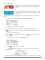
1
PVI 3800TL
PVI 5200TL
PVI 6600TL
PVI 7600TL
Installation and Operation Manual
Revision B
©2014, Solectria Renewables LLC
DOCR 070366-B
This manual is subject to change.
Please check our website at http://www.solren.com/products-and-services/documentation/
for the most recent version.
© Copyright – SOLECTRIA RENEWABLES, LLC. - All rights reserved.
This manual accompanies our equipment for use by the end users. The technical instructions and illustrations contained in this
manual are to be treated as confidential and no part may be reproduced without the prior written permission of SOLECTRIA
RENEWABLES, LLC. Service engineers and end users may not divulge the information contained herein or use this manual for
purposes other than those strictly connected with correct use of the equipment. All information and specifications are subject to
change without notice.
DOCR 070366-B
1
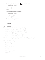
Table of Contents
1
General safety instructions
1.1
Safety symbols and terminology definitions
7
1.2
Safety instructions
8
2
Introduction
10
2.1
System
10
2.2
Data monitoring and communication
11
2.3
Technical structure of the inverter
11
2.4
Ambient temperature
12
2.5
Inverter DC input voltage range
12
2.6
Efficiency
13
2.7
Equipment overview
14
2.8
Inverter nameplate and safety labels
16
3
Installation
20
3.1
Visual inspection
21
3.2
Installation location
21
3.3
Mounting the inverter
22
3.4
4
2
6
Required torques for PVI inverters
Electrical connections
24
25
4.1
General safety
25
4.2
Utility AC voltage
26
4.3
AC circuit breaker requirements
28
4.4
Grounding electrode conductor (GEC)
28
4.5
Lightning and surge protection
28
4.6
Multiple inverters
28
4.7
PV string considerations
28
4.8
Inverter connections
29
4.8.1
General information
29
4.8.2
Opening the wiring box cover
31
4.8.3
Wiring box conduit openings
32
4.8.4
PV array string input connections
33
4.8.5
Selecting PV string fuse(s)
36
4.8.6
Inverter AC output wire connections
39
4.8.7
Inverter RS-485 communication connections
43
4.8.8
SolrenView external monitoring
44
DOCR 070366-B
5
Commissioning the PV system
45
5.1
Status LEDs
46
5.2
Display and keypad
46
5.2.1
Components
46
5.2.2
Display layout
47
5.2.3
Keys
47
5.2.4
General menu structure
47
5.3
Inverter turn-on procedure
48
5.4
Inverter turn-off procedure
48
5.5
Standard initial commissioning
48
5.5.1
Brief overview of the commissioning steps
48
5.5.2
Detailed description of the commissioning steps
48
5.6
Setting values
6
50
Production Information
52
6.1
Overview
52
6.2
Current data
53
6.3
Other statistics
54
6.4
Deleting statistics
56
7
Settings
57
7.1
Overview
57
7.2
Installation settings
57
7.2.1
Date and time
58
7.2.2
Date and time formats
58
7.2.3
Contrast
59
7.2.4
Grid selection
59
RS-485
60
7.2.5
7.3
Grid feed-in settings
7.4
Options settings
61
62
7.4.1
Shading
62
7.4.2
AFCI setting
63
7.4.3
AFCI self test
64
7.4.4
Arc fault clear
64
7.5
8
Standard menu
65
Diagnosis and maintenance
8.1
8.1.1
Operating states
66
66
Types of operating states
66
DOCR 070366-B
3
8.1.2
8.1.3
8.2
Factors influencing the operating state
66
Display of the actual operating state
67
Event log
68
8.2.1
Overview
68
8.2.2
External events menu
68
Change events menu
69
8.2.3
8.3
Trouble-shooting and correction
70
8.3.1
External events / Insulation and grounding failures
70
8.3.2
Internal failures
72
Other LED and display messages
73
8.3.3
8.4
Displaying grid settings
73
8.5
Internal log
74
8.6
9
10
Maintenance
74
Repair
74
Removal, transport, storage, disposal
75
10.1
Removal
75
10.2
Packaging
75
10.3
Transport
75
10.4
Storage
75
10.5
Disposal
75
11
Technical data
76
11.1
FCC compliance Information
79
11.2
Canadian compliance Information
79
12
Appendix
81
12.1
Overview of setting options
81
12.2
Order numbers
81
12.3
Overview of menu structure
81
12.3.1 "Go to menu" function
81
12.3.2 Installation settings (100)
82
12.3.3 Shading (210)
83
12.3.4 Production information (400)
83
12.3.5 Diagnostics and Alarms (600)
87
13.3.6 Software version/inverter data (700)
87
12.3.7 Standard menu (800)
88
13
Glossary
89
14
Certificates
90
15
Warranty
94
4
DOCR 070366-B
Figures
1.
PVI inverter output power vs ambient temperature curve
12
2.
PVI 3800TL DC input Voltage Range
12
3.
PVI 5200TL/PVI 6600TL/PVI 7600TL PV input DC Voltage Range
13
4.
PVI 3800TL Efficiency Plot
13
5.
PVI 5200TL/PVI 6600TL/PVI 7600TL Efficiency Plot
14
6.
Exterior view of inverter’s main components
14
7.
Lockable DC Disconnect
15
8.
Nameplate Label and Barcode Label Location
16
9.
Location of Caution Labels
17
10.
Dimensions of PVI 3800TL inverter
18
11.
Dimensions of PVI 5200TL/PVI 6600TL/PVI 7600TL inverters
18
12.
Wiring box connection
20
13.
Inverter clearances
22
14.
Dimension drawing of mounting plate
23
15.
Installing the mounting bracket and inverter on a wood stud wall
23
16.
240V / 120V Split Phase AC Grid
26
17.
208V Delta AC Grid
26
18.
208V / 120V WYE AC Grid
27
19.
240V Delta AC Grid
27
20.
240V / 120V Stinger leg AC Grid
27
21.
480V Delta AC Grid
27
22.
480V / 277V WYE AC Grid
27
23.
PVI 3800TL Inverter electrical diagram
30
24.
PVI 5200TL/PVI 6600TL/PVI 7600TL Inverter electrical diagram
30
25.
Removing the wiring box cover
31
26.
Wiring box conduit opening locations
32
27.
Wiring box conduit plug removal
32
28.
Conduit installation and wiring routing
33
29.
Wiring box - PV input connections
35
30.
Selecting PV string fuses
36
31.
String fuse replacement procedure
38
32.
Conduit installation and AC wiring routing
40
33.
PVI 3800TL - AC voltage loss in different wire sizes and lengths
41
34.
PVI 5200TL/PVI 6600TL/PVI 7600TL - AC voltage loss with different wire sizes and lengths
41
35.
Wiring box AC assembly - terminal labeling
42
36.
Inverter RS-485 system diagram
43
37.
RS-485 termination jumper
44
38.
RS-485 connector pin-out
44
39.
SolrenView gatewat HMI
45
DOCR 070366-B
5
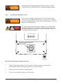
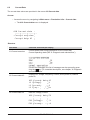
IMPORTANT SAFETY INSTRUCTIONS
SAVE THESE INSTRUCTIONS
1
General safety instructions
This manual contains important instructions for Solectria models PVI 3800TL, PVI 5200TL, PVI
6600TL and PVI 7600TL that should be followed during installation and maintenance of the inverter.
Solectria models PVI 3800TL, PVI 5200TL, PVI 6600TL and PVI 7600TL inverters are designed and
tested to meet all applicable North American and International safety standards. However, like all
electrical and electronic equipment, safety precautions must be observed and followed during installation and operation of Solectria inverters to reduce the risk of personal injury and to ensure a safe
installation.
Installation, commissioning, service, and maintenance of Solectria models PVI 3800TL, PVI 5200TL,
PVI 6600TL and PVI 7600TL inverters must only be performed by qualified personnel that are licensed and/or satisfy state and local jurisdiction regulations.
Before starting installation or commissioning of the Solectria PVI 3800TL, PVI 5200TL, PVI 6600TL
and PVI 7600TL, read through the entire manual and note all DANGER! WARNING! CAUTION!, and
NOTICE! statements.
All US electrical installations must comply and be in accordance with all the state, local, utility regulations, and National Electrical Code ANSI/NFPA 70.
For installations in Canada, please ensure these are done in accordance with applicable Canadian
standards.
Ce guide contient d’importantes instructions concernant les onduleurs solaires Solectria modèle PVI
3800TL, PVI 5200TL, PVI 6600TL et PVI 7600TL qui devant être observées au cours de l’installation
et de l’entretien de l’onduleur.
Les onduleurs solaires Solectria modèle PVI 3800TL, PVI 5200TL, PVI 6600TL et PVI 7600TL sont
conçus et testés pour répondre à toutes les normes de sécurité nord-américaines et internationales
applicables. Cependant, comme pour tous les équipements électriques et électroniques, des mesures
de sécurité doivent être respectées et observées durant l’installation et l’exploitation des onduleurs
Solectria afin de réduire le risque de préjudice corporel et de garantir la sécurité de l’installation.
L’installation, la mise en service, l’entretien et la maintenance des onduleurs solaires Solectria modèle
PVI 3800TL, PVI 5200TL, PVI 6600TL et PVI 7600TL doivent être entreprises uniquement par un personnel qualifié autorisé et/ou répondant aux critères des règlements locaux ou nationaux applicables.
Lisez l’intégralité du manuel et prenez note de toutes les déclarations relatives à la sécurité sous les
rubriques intitulées DANGER ! AVERTISSEMENT ! PRUDENCE ! et AVIS ! avant de commencer
l’installation ou la mise en service des onduleurs solaires PVI 3800TL, PVI 5200TL, PVI 6600TL et
PVI 7600TL.
Toutes les installations électriques nord-américaines doivent être conformes et respecter tous les règlements des services publics, nationaux, locaux ainsi que le National Electrical Code ANSI/NFPA 70.
Pour toute installation au Canada, veuillez vous assurer que les installations sont conformes aux
normes canadiennes applicables.
6
DOCR 070366-B
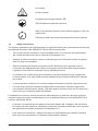
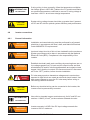
1.1
Safetysymbolsandterminologydefinitions
DANGER indicates a hazardous situation which, if not avoided,
will result in death or serious injury.
DANGER indique une situation dangereuse qui, si elle n’est pas
évitée, est susceptible de provoquer un décès ou des blessures
graves.
WARNING indicates a hazardous situation which, if not avoided,
could result in death or serious injury.
AVERTISSEMENT indique une situation dangereuse qui, si elle
n’est pas évitée, est susceptible de provoquer un décès ou des
blessures graves.
CAUTION indicates a hazardous situation which, if not avoided,
could result in minor or moderate injury.
PRUDENCE indique une situation dangereuse qui, si elle n’est
pas évitée, est susceptible de provoquer des blessures légères
ou de degré moyen.
NOTICE!
NOTICE indicates a situation that can result in property damage
if not avoided.
AVIS!
AVIS indique une situation susceptible de provoquer des dommages à la propriété, si elle n’est pas évitée.
INFORMATION!
INFORMATION provided that when known and used will ensure
optimal operation of the system.
INFORMATIONS!
La connaissance et l’utilisation des INFORMATIONS fournies garantissent un fonctionnement optimal du système.
HIGH VOLTAGE WARNING! Indicates hazardous high voltages
are present, which, if not avoided, will result in death or serious
injury. Thus, only authorized and trained personnel should install
and/or maintain this product.
AVERTISSEMENT HAUTE TENSION! indique la présence de
hautes tensions présentant un danger susceptibles de provoquer
un décès ou des blessures graves si elles ne sont pas évitées.
Par conséquent, l’installation et/ou l’entretien de ce produit doivent être entreprises uniquement par un personnel autorisé et
formé.
DOCR 070366-B
7
Hot surface
Surface chaude
Equipment grounding conductor (PE)
(PE) Équipement conducteur de terre
Wait for a prescribed amount of time before engaging in the indicated action.
Patientez le délai requis avant d’entreprendre l’action indiquée.
1.2
Safety Instructions
The inverter installation must be performed by an authorized electrician in accordance with the local
and National Electrical Code ANSI/NFPA 70 and OSHA requirements.
•
The inverter section contains no user-serviceable parts. For all service and maintenance,
the inverter should be returned to a Solectria Renewables, LLC.
•
Read all of these instructions, cautions, and warnings for the Solectria inverter and associated PV array documentation.
•
Before connecting the Solectria inverter to the AC distribution grid, approval must be
received by the appropriate local utility as required by national and state interconnection
regulations, and must be connected only by qualified personnel.
•
In operation, the inverter wiring and connections can have hazardous high voltages and
currents present, thus only authorized and qualified personnel shall install and/or maintain
the inverter.
•
In some operation instances, the inverter chassis and heatsink surfaces may become hot.
•
PV solar arrays produce hazardous voltages and currents when exposed to light which
can create an electrical shock hazard. Use dark opaque sheets to cover the PV solar array
before wiring or connecting cable terminations.
L’installation et la mise en service doivent être effectuées par un électricien autorisé conformément aux exigences locales et nationales ainsi qu’au National Electrical Code ANSI/NFPA 70 et
condition nécessaire OSHA.
•
L’onduleur ne comporte aucune pièce pouvant être réparée par l’utilisateur. Afin de réduire
les risques de choc électrique, contactez le personnel d’entretien qualifié de l’usine à propos
des opérations d’entretien de Solectria Renewables, LLC.
•
Lisez toutes les instructions, rubriques Prudence et Avertissement de l’onduleur Solectria,
ainsi que la documentation sur le panneau photovoltaïque associé.
8
DOCR 070366-B
•
Avant de connecter l’onduleur solaire Solectria au réseau de distribution du courant alternatif
(CA), une autorisation doit être obtenue de la part des services publics locaux de tutelle,
conformément aux règlements concernant l’interconnexion nationale et locale. La connexion
ne doit être effectuée que par un personnel qualifié.
•
Des courants et des tensions de hautes intensités dangereuses peuvent être présents dans
le câblage et les connexions de l’onduleur en marche, par conséquent, l’installation et/ou la
maintenance de l’onduleur doivent être entreprises uniquement par un personnel autorisé et
qualifié.
•
Sous certains régimes de fonctionnement, le châssis de l’onduleur et les surfaces des dissipateurs de chaleur peuvent devenir chaud.
•
Les panneaux solaires photovoltaïques produisent tensions et courants dangereux lorsqu’ils
sont exposés à la lumière et constituent un danger de choc électrique. Couvrez le panneau
solaire photovoltaïque à l’aide de morceaux de tissu opaques et foncés avant tout câblage
ou connexion des terminaisons de câble.
DOCR 070366-B
9
2
Introduction
With this device you have acquired an inverter for connection of a photovoltaic system to the grid.
This inverter is characterized by an advanced housing design and state-of-the-art high-frequency
technology, which enable the highest levels of efficiency and longest life.
The inverter includes key features and capabilities, such as Unintentional Islanding protection,
LCD, and RS-485 interfaces.
The inverter is usable indoors and outdoors. It meets the requirements of ANSI/NFPA 70, NEC
690.5, UL 1741, IEEE 1547 and IEEE 1547.1 for parallel operation of power generation plants on
low-voltage network of regional electrical utility companies.
The function of the Unintentional Islanding protection (automatic isolation point for in-plant generation systems) complies with UL 1741 / IEEE 1547 specifications.
In the following technical description, the precise functions are explained to the installer, as well as
the user, which are required for the installation, operational start-up and handling of the inverter.
2.1
System
The content of renewable energy with respect to overall power consumption worldwide is increasing annually by approximately 25%. The reason for this rise can be primarily attributed to the constantly increasing demand for power, the increasing interest in environmentally friendly technologies, as well as the increasing costs of non-renewable energy.
By the use of renewable energy sources, the earth‘s atmosphere can be enormously relieved of
increases in CO2 and other harmful gases which result from power generation.
The solar inverter converts direct current from the solar cells into alternating current. This enables
you to feed your self-produced solar energy into the public grid.
Thanks to efficient MPP tracking, maximum capacity utilization of the solar energy plant is ensured even in cases of misty and cloudy skies.
The string concept means that PV modules are always connected in series (in a string) and/or
that strings with the same voltage are connected in parallel to the solar inverter with the aim of
significantly reducing the photovoltaic system’s cabling requirements.
The fact that the modules are connected in strings also means that the photovoltaic system can be
perfectly matched to the solar inverter’s input voltage range.
The inverter is transformerless type without galvanic isolation. Therefore, the inverter may only be
operated with ungrounded PV arrays. Furthermore, the PV array must be installed in accordance
with the NEC690.35 (Ungrounded Photovoltaic Power Systems) and the locally valid regulations for
ungrounded PV arrays. Additionally, the PV array (PV modules and cabling) must have protective
insulation and the PV modules used must be suitable for use with this inverter. PV modules with a
high capacity to ground may only be used if the array coupling capacity does not excessed 1,200
nF with 60Hz grid.
10
DOCR 070366-B
2.2
Data monitoring and communication
The integrated data display, processing and communication of the device enables easy operation
of the solar inverter. Monitoring of the operational status and signaling of operational failures are
capable of being called up over the device display. The data interfaces enable the downloading of
data which can be evaluated with the aid of a PC system and allow continuous recording of operating data.
The best way of accessing this functionality is via a monitoring system, such as SolrenView, connected to your inverter.
The read-out of the data on the display is possible when the inverter is connected to AC voltage.
2.3
Technical structure of the inverter
The photovoltaic voltage is adjusted so that the maximum power output of the PV modules is also
achieved with different solar irradiation levels and temperatures (MPP-Tracking). These inverters
have quite wide MPP range of suit for variety of PV modules by a variety of manufacturers. Measures must be taken to ensure that the maximum no- load voltage of 600 V is never exceeded.
Please note that the maximum no-load voltage will occur at the lowest temperatures anticipated.
You will find more detailed information about temperature dependency in the data sheet for the PV
modules.
The high-quality aluminum casing corresponds to protection degree NEMA 4 / IP65 (water-jet proof
and dust-proof) and is protected by an anti-corrosion finish. The heat sink on the inverters
is designed in such a way that operation of the inverter is possible at ambient temperatures from
-13°F to +122°F (-25°C to +50°C) at full power and optimal efficiency for either 240 Vac or 208 Vac
AC grids.
Metal fins designed into the rear side of the inverter chassis are used to dissipate heat and protect
the unit. An internal temperature control protects the interior of the device. In case of high ambient
temperatures, the maximum transferable power is limited.
The solar inverter is controlled by microcontrollers which provide interface communication and the
values and messages on the front-panel display.
AC grid monitoring is done by an independent dedicated micro controller set up to meet the requirements of UL 1741 / IEEE 1547. This enables a connection of the solar inverter to the in-house grid.
Operator protection requirements are met by electrically isolating the grid from the PV module. The
electrical isolation between the grid and the PV module is equivalent to basic insulation. Maximum
operator protection is ensured by reinforced isolation between the grid, PV modules and accessible
interfaces (display, RS-485 interface and fan port). Relevant standards concerning electromagnetic
compatibility (EMC) and safety are fulfilled.
The solar inverter is functional in grid-parallel operation exclusively. An automatically Unintentional
Islanding function, which was accepted by a certification agency, guarantees secure disconnection
in case of circuit isolation or interruptions in power supply and avoid isolated operation.
DC arc-fault circuit interrupt (AFCI) is integrated into the Solectria PVI 3800TL, PVI 5200TL, PVI
6600TL and PVI 7600TL. It complies the requirement as Type 1 device in UL1699B standard,
series arc faults can be detected.
DOCR 070366-B
11
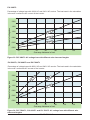
2.4
Ambient temperature
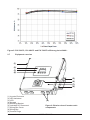
The inverter can be operated in ambient temperatures between -13°F to 158°F (-25°C to +70°C).
The following diagram illustrates how the power of the inverter is derated depending on ambient
temperature.
The device should be installed in a well-ventilated, cool and dry location.
100%
90%
Nominal Output Power
80%
70%
60%
50%
40%
30%
20%
10%
0%
30 °C
40 °C
100% Nom. output pwr
@ 200 V
50 °C
60 °C
70 °C
100% Nom. output pwr
@ 380 V
80 °C
Nom. output pwr
@ 500 V
Figure 1 demonstrates typical
behavior for PVI 3800-7600TL
series inverters.
Figure 1: Solectria PVI 3800-7600TL inverter output power vs ambient temperature curve
2.5
Inverter DC input voltage range
Figure 2: Solectria PVI 3800TL DC input voltage range
Notice: Start up voltage is 150 Vdc; full power MPPT voltage is 200 Vdc
12
DOCR 070366-B
Figure 3: PVI 5200TL, PVI 6600TL and PVI 7600TL PV input DC voltage range
2.6
Efficiency
The best efficiency of the inverter is obtained at input voltages > 320Vdc for 208Vac grid, and input
voltages > 380Vdc for 240Vac grid.
Figure4:PVI3800TLefficiencyplotat240Vac
DOCR 070366-B
13
Figure5:PVI5200TL,PVI6600TLandPVI7600TLefficiencyplotat240Vac
2.7
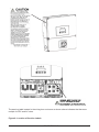
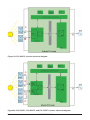
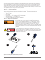
Equipment overview
(1)
(2)
(3)
(4)
(5)
(6)
(7)
(8)
(1) Inverter Enclosure
(2) LED Indicators
(3) LCD
(4) Keypad
(5) Mounting Bracket
(6) Lockable DC Disconnect
(7) Wiring Box Cover
(8) Wiring Box
(9) Conduit Plugs
14
(9)
Figure 6: Exterior view of inverter main
components
DOCR 070366-B
A further description of the equipment features:
(1) Inverter Enclosure - This section is sealed at the factory and there are no user-serviceable
parts inside. All wiring to install the inverter is done in the wiring compartment.
(2) LED Indicators - The three LED indicators show errors or status as described in Section 5.
(3) LCD - The 20 character, 4 line LCD shows important messages regarding the inverter status
and performance.
(4) Display Control Keys - These 4 keys allow the user to access status and performance information and to change settings via the display.
(5) Mounting Bracket - The inverter ships with a mounting bracket that allows for easy installation
of the inverter to a wall.
(6) Lockable DC Disconnect - The DC disconnect is lockable and allows DC power to be disconnected from the inverter. See figure 7 below.
(7) Wiring Box Cover - This is the cover for the wiring compartment. The removal procedure is
shown on page 29. Please note the DC disconnnect must be in the OFF position before this
cover can be removed.
(8) Wiring Box - This is the compartment where all the wiring for the inverter inputs and outputs
plus the RS-485 communication is done.
(9) Conduit Opening - There are six - 1“ conduit openings and two - 1/2“ conduit openings. Each
conduit opening comes fitted with a conduit plug that should be removed before installing conduit
fittings. Conduit fittings need to be water tight with a NEMA 4, 4X, 6, or 6X rating.
Off
On
OFF
Figure 7: Lockable DC Disconnect
DC Disconnect shown with lock in off position. There are three openings on the disconnect where
a lockout padlock can be attached as shown above.
DOCR 070366-B
15
2.8
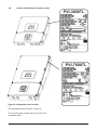
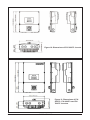
Inverter Nameplate and Safety Labels
Figure 8: Nameplate Label location
The nameplate label is shown in figure 8.
The inverter serial number can be found on the
nameplate label.
16
DOCR 070366-B
The warning label located in the wiring box enclosure as shown above indicates that there are
multiple live DC and AC wires.
Figure 9: Location of Caution Labels
DOCR 070366-B
17
Figure 10: Dimensions of PVI 3800TL inverter
Figure 11: Dimensions of PVI
5200TL, PVI 6600TL and PVI
7600TL inverters
18
DOCR 070366-B
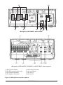
(1)
(2)
(3)
(5)
(4)
(5) (6)
(7)
(8)
Wiring box of PVI 3800TL solar inverter
Wiring box of PVI 5200TL, PVI 6600TL and PVI 7600TL solar inverters
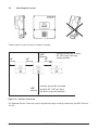
(1) String Fuse Holders
(2) RS-485 communication ports
(3) PV Positive Terminals
(4) PV Negative Terminals
(5) Grounding Terminals
(6) AC side Neutral
(7) AC side L1
(8) AC side L2
Figure 12: Wiring box connection options
DOCR 070366-B
19
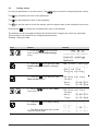
Required torques for wiring box terminals
Terminals in Figure 12
3, 4, 5, 6, 7, 8 (see location and
description above)
Wire size permitted
14 - 6 AWG (2.5 - 16 mm2)
Required torque*
10.5 in-lbs (1.2 Nm)
Table 1: Required torques for wiring box terminals
3
Installation
WARNING!
Read all of these instructions, cautions, and warnings for the Solectria PVI inverter and associated PV array documentation.
AVERTISSEMENT!
WARNING!
AVERTISSEMENT!
WARNING!
AVERTISSEMENT!
WARNING!
AVERTISSEMENT!
CAUTION!
PRUDENCE!
CAUTION!
PRUDENCE!
INFORMATION!
INFORMATIONS!
20
Installation and commissioning must be performed by a licensed
electrician in accordance with local, state, and National Electrical
Code ANSI/NFPA 70 requirements.
The installation and wiring methods used in the installation of this
inverter in the U.S. must comply with all US National Electric Code
requirements (NEC) and local Authority Having Jurisdiction (AHJ)
requirements. In Canada, the installation and wiring methods used
must comply with the Canadian Electric Code, parts I and II, and
the local AHJ requirements. System grounding when required by
the Canadian Electrical Code, Part 1, is the responsibility of the
installer.
These servicing instructions are for use by qualified personnel only.
To reduce the risk of electric shock, refer all servicing to factory
qualified service personnel. No user serviceable are contained
inside the inverter.
To reduce the risk of fire, connect only to a circuit provided with
dedicated circuit overcurrent protection in accordance with the
National Electrical Code, ANSI/NFPA70.
The unit or system is provided with fixed trip limits and shall not be
aggregated above 30KW on a single point of common connection.
In order to be able to carry out an accurate energy measurement,
a revenue meter measuring kWh may be used between the feed-in
point and the inverter.
DOCR 070366-B
3.1
Visual inspection
All Solectria PVI inverters are 100% tested, packaged in a heavy duty cardboard shipping carton,
and visually inspected before leaving our manufacturing facility. If you receive the inverter in a
damaged shipping carton, please reject the shipment and notify the shipping company immediately.
Verify Solectria PVI shipping carton contains:
a. Correct Solectria PVI inverter model: PVI 3800TL, PVI 5200TL, PVI 6600TL or PVI 7600TL
b. Mounting bracket
c. Operation and Installation Manual
Visually inspect the Solectria PVI inverter for any physical damage such as a bent heatsink fin or
a dented chassis.
If the inverter appears to be damaged or if the inverter needs to be returned, please contact
Solectria customer service.
WARNING!
No user serviceable parts are contained in the inverter. Do
not attempt to open or repair the inverter. The inverter is factory
sealed to maintain its NEMA 4 rating. Breaking the seal will void the
inverter warranty.
AVERTISSEMENT!
3.2
Installation location
1.
Install the inverter on a non-flammable support base.
2.
The inverter must be mounted vertically on a flat surface.
3.
For clearances around inverter, see Figure 13.
4.
Ensure the mounting hardware and structure can support the weight of the inverter.
5.
Ensure the mounting hardware meets the appropriate building code.
6.
Avoid installation on resonating surfaces (light construction walls etc.).
7.
Installation can be indoors or in protected outdoor areas.
8.
Avoid direct sun exposure.
9.
Ensure inverter ambient temperature is within -13°F to +122°F (-25°C to +50°C) for optimal
efficiency of the PV system.
10.
Chose a mounting height that allows easy access viewing of the display.
11.
Despite having a NEMA 4 / IP65 enclosure with a soiling category III certification, the inver
ter must not be exposed to heavy soiling.
12.
Unused connectors and interfaces must be covered by sealing connectors.
DOCR 070366-B
21
3.3
Mounting the inverter
Please make sure the inverter is installed vertically.
>20"
(50.8 cm)
>4"
>6"
>6"
(10 cm)
(15.2 cm)
(15.2 cm)
>39"
(100 cm)
Inverter should be at least
20“ (50.8 cm) from any
ceiling surface
Inverter should be mounted
at least 39“ (100 cm) from
the floor or ground surface.
Figure 13: Inverter clearances
The National Electric Code may require significantly larger working clearances (see NEC Section
110.26)
22
DOCR 070366-B
Figure 14: Dimensional drawing of the mounting plate
1.
Mount the mounting plate to the wall with at least 4 screws and anchors (Ø 1/4“). With 4
screws, use either all four 6.5mm mounting holes or all 4 slotted mounting holes. You can
use the mounting plate as a template for marking the positions of the boreholes.
2.
Tighten the screws firmly to the wall.
Figure 15: Installing the mounting bracket and inverter on a wooden stud wall.
DOCR 070366-B
23
1.
Using the mounting bracket as a template, mark four screw holes onto the wall. For 16 in.
(40.6 cm) on center stud mounting, use the four holes, marked A in Figure 4 on the prior
page. Make sure the holes are in the center of each stud before marking the drill location.
2.
After marking the screw hole locations, drill the pilot holes for the appropriate screw type
that will hold the weight of the inverter in the selected material. 1/4“ lag bolts are recommended for mounting on wood framed walls.
3.
Align the mounting bracket over the pilot holes and install the mounting hardware flush to
mounting surface. Please tighten to the recommended torque necessary to hold the
mounting bracket firmly to the wall surface.
4.
Becasue the inverters are heavy, they should be lifted out of the cardboard container by at
least two people (PVI 3800TL weighs 43 lbs (19.5 kg) and PVI 5200/6600/7600TL weigh 65
lbs (29.5 kg)).
5.
With two people, lift up the inverter and place it carefully onto the mounting bracket. Install
two locking nuts as shown in Figure 15 to secure the device.
6.
Check that the inverter is seated securely on the wall.
It is recommended to use stainless steel screws, especially if installed outdoors. Be sure to
verify sheer and pullout strength of anchors or other wall attachments.
3.4
Required torques for PVI inverters
Part
Wiring Box Cover
Screws
Description
Torx T30 screws (x4) for
attaching the wiring box
cover to the wiring box
Required torque
max. 71 in-lbs (8 Nm)
Wiring Box Interior
Nuts
10mm nuts (x4) that secure max. 71 in-lbs (8 Nm)
the wiring box to the inverter stage assembly
Table 2: Required Torques for PVI inverters
24
DOCR 070366-B
Tooling
Torx T30
10mm wrench
4
Electrical connections
4.1
General safety
WARNING!
Read all of the instructions, cautions, and warnings for the Solectria
PVI inverter and associated PV array documentation.
AVERTISSEMENT!
WARNING!
AVERTISSEMENT!
DANGER!
DANGER!
WARNING!
AVERTISSEMENT!
CAUTION!
PRUDENCE!
CAUTION!
PRUDENCE!
Installation and commissioning must be performed by a licensed
electrician in accordance with local, state, and National Electrical
Code ANSI/NFPA 70 requirements. Use 90°C (194 °F) copper solid
or stranded wire only for all DC and AC wiring to the PVI inverter
to optimimize system efficiency. Size conductors per NEC requirements.
PV solar arrays produce hazardous voltages and currents when
exposed to light which can create an electrical shock hazard. Use
dark opaque sheets to cover the PV solar array before wiring or
connecting cable terminations.
Before connecting the Solectria PVI inverter to the AC distribution
grid, approval must be received by the appropriate local utility as
required by national and state interconnection regulations, and must
be connected only by qualified personnel.
Do not attempt to open or repair the inverter. The inverter is factory
sealed to maintain its NEMA 4 / IP65 rating. Breaking the seal will
void the inverter warranty.
The AC output circuits are isolated from the enclosure. When
required, providing PV system grounding electrode conductor (GEC)
is the responsibility of the installer. See NEC 690.41. 690.42, and
690.43.
DOCR 070366-B
25
4.2
Utility AC voltage
The Solectria PVI inverters operate grid-tied to the utility voltage. PVI inverters are software configurable via the user display panel for various 208 Vac or 240 Vac 60 Hz service configurations as
shown in figures 16-22.
CAUTION!
PRUDENCE!
The Solectria PVI Inverters must never be connected to a
120 Vac utility service. NEC 690.64(b)(1) requires that the inverter
be connected to a dedicated circuit with no other outlets or devices
connected to the same circuit.
AC connection voltage and frequency limits:
Voltage range for 208 V nominal, line to line
Voltage range for 240 V nominal, line to line
Frequency Range
183 V - 228 V
211 V - 264 V
59.3 Hz - 60.5 Hz
Table 3: AC connection voltage and frequency limits
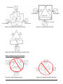
Gridconfigurationsallowed:
PVI Inverter
PVI Inverter
PVI Inverter
Figure 16: 240V/120V Split Phase AC Grid
26
PVI Inverter
DOCR 070366-B
Figure 17: 208V Delta AC Grid
PVI Inverter
PVI Inverter
PVI Inverter
PVI Inverter
PVI Inverter
PVI Inverter
Figure 19: 240V Delta AC Grid
Figure 18: 208V/120V WYE AC Grid
Figure 20: 240V/120V Stinger-Leg AC Grid
GridConfigurationsNOTAllowed:
Figure 21: 480V Delta AC Grid
Figure 22: 480V/277V WYE AC Grid
DOCR 070366-B
27
4.3
AC circuit breaker requirements
A dedicated over current protection device in the building circuit panel is required for each Solectria PVI inverter. There must be a circuit breaker or fuse to protect each AC phase, L1 and L2.
The over current protection device should be able to handle the rated maximum output voltage
and current of the inverter. Please refer to the table below to determine the appropriate circuit
breaker size to avoid potential fire hazards. The National Electrical Code (NEC), ANSI/NFPA 70
or applicable local electrical codes must be followed when determining maximum branch-circuit
over-current protection requirements.
Inverter model
Maximum AC branch protection
PVI 3800TL
2-pole, 20 A 208/240 Vac
PVI 5200TL
2-pole, 40 A 208/240 Vac
PVI 6600TL
2-pole, 40 A 208/240 Vac
PVI 7600TL
2-pole, 40 A 208/240 Vac
4.4
Grounding Electrode Conductor (GEC)
Per NEC 690.47, a GEC must be installed, and the Grounding Electrode Terminal (GET) conductor must be sized in accordance with NEC article 250.166. The GET conductor should be terminated at the GET screw terminal inside the wiring box compartment.
4.5
Lightning and surge protection
Solectria PVI inverters are designed and certified to meet stringent UL 1741 / IEEE 1547 and
ANSI/ IEEE 62.41/62.42 AC lighting and surge requirements; however, every PV installation is
unique, thus additional external UL/NEC AC and DC surge protection and solid grounding practice
are recommended. The inverter comes equipped with class II AC and DC surge arrestors.
4.6
Multiple inverters
Multiple Solectria PVI inverters are permitted at a common location if all applicable NEC, state,
local building codes and local utility commissioning guidelines are met. However, each inverter
must have its own dedicated AC overcurrent protection device and a separate PV array.
4.7
PV string considerations
There are a large number of PV module string combinations that will offer optimal performance
from either the PVI 3800TL, PVI 5200TL, PVI 6600TL and PVI 7600TL inverters due to their wide
MPP DC voltage range (200 V – 500 V). Please use Solectria‘s online string sizing tool at
www.solectria.com/string-sizing-tool.
28
DOCR 070366-B
INFORMATION!
INFORMATIONS!
CAUTION!
PRUDENCE!
If string sizing is done manually, follow the temperature multiplication factors given in NEC 690.7 table or the PV module manufacturer specified temperature coefficient to ensure PV string voltage is
less than < 600 Vdc at minimum design temperature
System wiring voltage losses should be no greater than 2 percent
on DC and AC side for optimal system efficiency and performance.
4.8
Inverter connections
4.8.1
General information
WARNING!
AVERTISSEMENT!
WARNING!
AVERTISSEMENT!
WARNING!
AVERTISSEMENT!
DANGER!
DANGER!
CAUTION!
PRUDENCE!
INFORMATION!
Installation and commissioning must be performed by a licensed
electrician in accordance with local, state, and National Electrical
Code ANSI/NFPA 70 requirements.
Input and output circuits of this unit are isolated from the enclosure.
System grounding must be done in accordance with the National
Electrical Code (NEC). Compliance is the responsibility of the
installer.
Establish electrically safe work conditions by ensuring there are no
live voltages present on PV input and AC output circuits and that
all dedicated DC and AC disconnects/breakers are locked out and
tagged. Verify that the inverter‘s DC disconnect and AC disconnect
are in the “OFF” position, before inverter installation.
PV solar arrays produce hazardous voltages and currents when
exposed to light which can create an electrical shock hazard. Use
dark opaque sheets to cover the PV solar array before wiring or
connecting cable terminations.
Before any electrical wiring can be connected to the inverter, the
inverter must be permanently mounted.
Use solid or stranded copper conductors only for AC and DC connections. 6 AWG (16 mm2) is the maximum allowed wire size.
INFORMATIONS!
WARNING!
Inverter warranty is VOID if the DC input voltage exceeds the
inverter‘s 600 Vdc maximum.
AVERTISSEMENT!
DOCR 070366-B
29
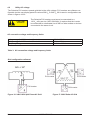
A
B
Figure 23: PVI 3800TL Inverter electrical diagram
A
B
C
D
Figure 24: PVI 5200TL, PVI 6600TL and PVI 7600TL Inverter electrical diagram
30
DOCR 070366-B
POWER IS FED FROM MORE THAN ONE SOURCE, MORE
THAN ONE LIVE CIRCUIT EXISTS. Please see diagram above.
WARNING!
AVERTISSEMENT!
4.8.2
Opening the wiring box cover
Ensure no live voltages are present on PV input and AC output
circuits, and verify that the DC disconnect is in the “OFF” position,
and that are dedicated AC and DC disconnects/breakers locked out
before inverter installation.
WARNING!
AVERTISSEMENT!
DANGER!
DANGER!
PV solar arrays produce hazardous voltages and currents when
exposed to light which can create an electrical shock hazard. Use
dark opaque sheets to cover the PV solar array before wiring or
connecting cable terminations.
DC Disconnect switch in
OFF position
Torx T30
Figure 25: Removing the wiring box cover
1.
Place DC Disconnect switch in “OFF” position. Please note the cover cannot be
removed when the DC Disconnect switch is in the “ON” position.
2.
Remove the 4 cover screws indicated above.
3.
Lift the cover upward and place it off to the side.
DOCR 070366-B
31
4.8.3
Wiring box conduit openings
Conduit openings are provided for 1 inch and ½ inch conduit fittings. If the conduit fitting used
is between 1 inch and ½ inch (2.54 cm and 1.27 cm), an appropriate conduit reducer should be
used.
1 in.
1 in.
1 in. 1 in.
1 in.
1 in.
1/2 in.
Figure 26: Wiring box conduit opening locations
CAUTION!
PRUDENCE!
Do not enlarge the wiring compartment conduit openings as the
wiring box enclosure will be damaged which will void the inverter
warranty.
The conduit plugs are removed by placing a flat head screwdriver in the slot
on the conduit plug face and turning it
while gripping the nut on the inside of
the enclosure. Unscrew the nut from
the conduit plug and slip the conduit
plug out of the conduit opening.
Figure 27: Wiring box conduit plug removal (illustration showing
the removal of a conduit plug)
32
DOCR 070366-B
0.5 inch
6 inches
Figure 28: Conduit installation and wiring routing
Conduit fittings need to be water tight with either a NEMA 4, 4X, 6, or 6X rating.
Once conduit and fittings are installed, route wiring through the conduit and fitting and allow a 6
inch strain relief service loop within the wiring box compartment.
4.8.4
PV array string input connections
DANGER!
DANGER!
To ensure maximum protection against hazardous contact voltages
while assembling photovoltaic installations, both the positive and
the negative leads must be strictly isolated electrically from the
ground. All string fuses must be removed from the wiring box.
–
Risk of electric shock and fire. Use only with PV modules that
are listed for use with system voltage of 600V.
–
Electric shock hazard. The DC conductors of this photovoltaic
system are ungrounded and may be energized.
–
Electric shock hazard. The DC conductors of this photovoltaic
system are ungrounded but will become temporarily
grounded without indication when the inverter measures
the PV array isolation.
–
Verify all DC source circuit voltages and polarities with a volt
meter because damage to the inverter could result if incorrect
DC input voltages or polarity is connected to it. After verification of correct voltage and polarity, DC fuses can be installed.
WARNING!
AVERTISSEMENT!
CAUTION!
PRUDENCE!
DOCR 070366-B
33
INFORMATION!
INFORMATIONS!
INFORMATION!
INFORMATIONS!
34
The PV Array positive or negative leads must not be connected to
ground.
All screw terminals accept solid or stranded copper 14 – 6 AWG
wire only. A torque wrench with a flat head screw driver is recommended for tightening screw terminals to a 10.5 in-lbs. (1.2 Nm)
torque.
DOCR 070366-B
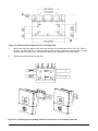
B
A
-
+
A PV Positive Terminals
B PV Negative Terminals
PVI 3800TL wiring box diagram
A
C
+
B
-
+
D
-
A PV1_Positive Terminals
B PV1_Negnative Terminals
C PV2_Positive Terminals
D PV2_Negnative Terminals
PVI 5200TL/PVI 6600TL/PVI 7600TL wiring box diagram
Figure 29: PVI Wiring box - PV input connections
DOCR 070366-B
35
1.
Verify that the exposed wires are at least 6 inches in length to provide adequate strain
relief and wire end strip length. Secure the conduit into both fittings then tighten conduit fit
tings to manufacturer’s recommended torque.
2..
Connect the positive lead from each PV array string to 1 of the PV Positive Terminals (A) in
the wiring box compartment. Using a torque wrench, tighten the screw terminal to 10.5
in-lbs (1.2 Nm) of torque.
3.
Connect the negative lead from each PV array string to 1 of the PV Negative Terminals (B)
in the wiring box compartment using a torque wrench, tighten the screw terminal to 10.5
in-lbs (1.2 Nm) of torque.
4.8.5
Selecting PV string fuse(s)
A
A = 4 String Fuse Holders
B = 8 String Fuse Holders
B
Figure 30: Fuse string locations
36
DOCR 070366-B
4.8.5.1
PV string fuse information and calculating string fuse size
The PVI 3800TL, PVI 5200TL, PVI 6600TL, and PVI 7600TL inverters are shipped with 3 X 15 A
600Vdc Littlefuse KLKD 15 string fuses. The provided string fuses may or may not be appropriate
for your particular installation. Proper sizing of overcurrent protection is based on the maximum
short circuit current Isc (module) and calculated in accordance with NEC Article 690 requirements.
NOTICE!
The maximum acceptable string fuse for the string combiner is 20A
PV (KLKD 20) fuse. Use of larger fuses will void the warranty.
AVIS!
WARNING!
AVERTISSEMENT!
4.8.5.1.1
The string fuse rating should never exceed the Maximum Series
Fuse Requirment provided by the module manufacturer. This value
is typically listed on the module label.
Calculating the minimum string fuse per NEC Article 690
The minimum string fuse size is calculated by multiplying the module Isc x 1.56.
For example: if you are using modules that have an Isc = 6.25 A, you would calculate the minimum string fuse size as follows:
String Fuse (minimum) = 6.25 A x 1.56 = 9.75 A
A partial listing of the Littelfuse KLKD Fuses is as shown.
Part Number
Amperage
Type
KLK D 008. ............................ 8 A ...........................PV Fuse
KLK D 009. ............................ 9 A ...........................PV Fuse
KLK D 010. ............................ 10 A .........................PV Fuse
KLK D 012. ............................ 12 A .........................PV Fuse
KLK D 015. ............................ 15 A .........................PV Fuse
KLK D 020. ............................ 20 A .........................PV Fuse
DOCR 070366-B
37
It is worth noting that for this example we calculated the minimum series fuse rating. However, it
may be appropriate to use the supplied 15 A fuses as long as they do not exceed the maximum
series fuse rating (provided by the module manufacturer) or the overcurrent protection requirements of your PV source wires. Please reference the appropriate NEC Article(s) for further discussion regarding proper sizing of overcurrent protection.
4.8.5.1.2
PV fuse properties
Other fuse manufacturers may have compatible fuse types. The generic properties are:
•
•
•
•
•
Type: PV Fuse
Fast-acting
Dimensions: 1 1/2” in length x 13/32” fuse diameter
Interrupt Rating: >= 10 kA @ 600 Vdc
UL and CSA approval of the fuse is mandatory
4.8.5.2
String fuse replacement
WARNING!
AVERTISSEMENT!
DANGER!
DANGER!
String fuses shall only be replaced by a qualified professional.
Ensure no live voltages are present on PV input and AC output
circuits, and verify that the DC disconnect, AC disconnect, and
dedicated AC branch circuit breaker are in the “OFF” position,
before attempting to replace DC fuses. With a DC amperage clamp
meter, ensure that there is no current flowing through the fuse to be
replaced.
PV solar arrays produce hazardous voltages and currents when
exposed to light which can create an electrical shock hazard. Using
dark opaque sheets, cover the PV solar array before tampering or
reinserting PV string fuses
1
2
3
4
Figure 31: String fuse replacement procedure
38
DOCR 070366-B
Note: Refer to Figure 31 for String Fuse Locations.
1.
Verify the absense of DC current in each string with a DC clamp meter.
2.
Gripping only the plastic tab on top of the fuse extractor, pull straight upwards without
touching the fuse’s metal end caps or fuse-holder clips on printed circuit board.
3.
Away from open wiring box compartment, open the fuse extractor door and tilt fuse
extractor downward with a hand underneath to catch fuse as it slides out of fuse extractor.
4.
Next place the replacement fuse into fuse extractor and tilt upward to keep fuse from
dropping out. Close the fuse extractor door.
5.
With fuse/fuse extractor parallel to empty fuse position, lower fuse extractor while aligning
fuse caps with open fuse clips. Then push downward until the fuse snaps into the clips.
Follow the same procedure for replacing the other string fuses.
4.8.6
Inverter AC output wire connections
WARNING!
–
Read all of the instructions, cautions, and warnings for the
Solectria PVI Inverter and associated PV array documentati
on.
–
Installation and commissioning must be performed by a
licensed electrician in accordance with local, state, and
National Electrical Code ANSI/NFPA 70 requirements.
–
Ensure no live voltages are present on PV input and AC
output circuits, and verify that the DC disconnect, AC
disconnect, are in the “OFF” position, before inverter installati
on.
–
Verify that the dedicated 2-pole 240 Vac / 208 Vac circuit
breaker in the building electrical service panel is turned-off and
locked out.
AVERTISSEMENT!
INFORMATION!
INFORMATIONS!
All screw terminals accept solid or stranded copper 14 – 6 AWG
wire only. A torque wrench is recommended for tightening screw
terminals to a 10.5 in-lbs (1.2 Nm) torque.
.
DOCR 070366-B
39
0.5 inch
6 inches
Figure 32: Conduit installation and AC wiring routing
Conduit fittings need to be water tight with either a NEMA 4, 4X, 6, or 6X rating.
Once conduit and fittings are installed, route wiring through the conduit and fitting and allowing a
6 inch strain relief loop within the wiring box compartment.
Determine the AC voltage loss in the AC wires for a given wire cross section and wire length. The
following pages contain diagrams for each PVI inverter model to help determine the best wire size
for your particular installation. Solectria recommends that you select a wire size and length to ensure a maximum voltage. Please note that the diagrams only show approximate voltage loss and
more precise voltage loss should be calculated by a licensed electrician in accordance with local,
state, and National Electrical Code ANSI/NFPA 70 requirements. The conductor size shall not be
smaller than the 750C wire size based on the ampacities given in table 310.16 of the NEC, ANSI/
NFPA 70 and an addtional derating factor of 125% as indicated by UL1741.
40
DOCR 070366-B
PVI 3800TL
Percentage of voltage loss with 208 V AC and 240 V AC service. The load used in the calculation
is the max. continuous AC current of the inverter.
2.0%
Percent of voltage loss
1.6%
G
AW
1.2%
10
0.8%
8 AWG
0.4%
6 AWG
0.0%
20
40
60
80
100
120
140
One way distance in feet
Figure 33: PVI 3800TL-AC voltage loss with different wire sizes and lengths
PVI 5200TL, PVI 6600TL and PVI 7600TL
Percentage of voltage loss with 208 V AC and 240 V AC service. The load used in the calculation
is the max. continuous AC current of the inverter.
AW
G
2.0%
Percent of voltage loss
10
1.6%
G
W
8A
1.2%
G
6 AW
0.8%
0.4%
0.0%
20
40
60
80
100
120
140
One way distance in feet
Figure 34: PVI 75200TL, PVI 6600TL and PVI 7600TL AC voltage loss with different wire
sizes and lengths
DOCR 070366-B
41
A B
C D
E
AC-side
Terminals
A PE Terminal (AC System Ground)
D L1 Terminal
B N Terminal
E GET (Grounding Electrode Terminal)
C L2 Terminal
Figure 35: Wiring box AC assembly – terminal labeling
NOTICE!
AVIS!
WARNING!
AVERTISSEMENT!
Stranded copper wire should be checked for all strands inside the
terminal opening.
An additional external AC disconnect may be required by your
local AHJ. Please check local regulations to determine if the AC
disconnect is required for your installation.
1.
Mount the external AC disconnect (if required by local AHJ) near the inverter.
2.
Install conduit fitting and conduit into the wiring box compartment from AC disconnect or
utility service panel.
3.
Route AC wiring through conduit and verify that the exposed wires are at least 6 inches
in length to provide adequate strain relief and wire end strip length. Secure the conduit into
both fittings then tighten conduit fittings to manufacturer’s recommended torque.
4.
Terminate inverter’s AC output wires inside the AC disconnect or junction box.
– Connect the AC system GND wire to the PE screw terminal (A) and using a 3/16“ (4
mm) flat blade cabinet screw driver tighten the screw terminal to to 10.5 in-lbs (1.2 Nm)
of torque.
42
DOCR 070366-B
– Connect the Neutral wire to the “N” screw terminal (B), and using a torque wrench,
tighten the screw terminal to to 10.5 in-lbs (1.2 Nm) of torque.
– Connect L1 wire to the “L1” terminal (D), and using a torque wrench, tighten the screw terminal to to 10.5 in-lbs (1.2 Nm) of torque.
– Connect L2 wire to the “L2” terminal (C), and using a torque wrench, tighten the screw terminal to to 10.5 in-lbs (1.2 Nm) of torque.
NOTICE!
AVIS!
NOTICE!
AVIS!
4.8.7
Stranded copper wire should be checked for all strands inside the
terminal opening.
If a neutral wire connection is required for the connection grid to
make sure the neutral wire is securely connected to the neutral
terminal. Loose neutral wire connection will result in incorrect grid
voltage detection.
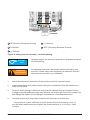
Inverter RS-485 communication connections
WARNING!
AVERTISSEMENT!
Read all of these instructions, cautions, and warnings for the Solectria PVI inverter and associated PV array documentation first.
Interface connection RS-485
The Solectria PVI inverters offer an RS-485 communication interface which can address up to 16
daisy chained inverters. For optimal performance, the last inverter in the chain must always have
the termination jumper placed in the “on” position.
NOTE: up to 1000‘ total length of RS-485
cables possible depending on site specifics.
J1=RS-485 port 1
J2=RS-485 port 2
Figure 36: Inverter RS-485 system diagram
DOCR 070366-B
43
The Termination Jumper is shown in the diagram on the left. To enable
termination place the jumper over the two upper pins next to the “on” label
on the board. To disable termination place the jumper in the off position on
the lower two pins.
RS485-2 RS485-1
on
off
J1
J2
Figure 37: RS-485 Termination Jumper
RS-485 connector pin-out
Figure 38: RS-485 connector pin-out
RS-485 data format
Baud Rate
Data Bit
Stop Bit
Parity
Programmable, 2400/4800/9600/19200/38400, default = 19200
8
1
N/A
Contact Solectria for available 485 cables for daisy-chaining multiple inverters or connecting
them to a SolrenView data monitoring logger.
4.8.8
SolrenView External Monitoring
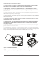
The PVI 3800TL, 5200TL, 6600TL and 7600TL inverters include an option for a SolrenView
external gateway. This device can be used for the purpose of webbased monitoring and data
logging.
From the inverter a user can configure and monitor the inverter using a human-machine interface
(HMI). This HMI consists of the LCD and four buttons.
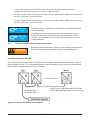
The backside of SolrenView gateway provides connectivity to the data monitoring system.
Solectria Renewables’ SolrenView web-based data monitoring system can be interfaced using
Ethernet over twisted pair.
44
DOCR 070366-B
Figure 39: SolrenView Gateway HMI
5
Commissioning the PV system
WARNING!
Read all of these instructions, cautions, and warnings for the
Solectria PVI inverter and associated PV array documentation.
AVERTISSEMENT!
WARNING!
AVERTISSEMENT!
Installation and commissioning must be performed by a licensed
electrician in accordance with local, state, and
National Electrical Code ANSI/NFPA 70 requirements.
DOCR 070366-B
45
WARNING!
AVERTISSEMENT!
NOTICE!
AVIS!
5.1
Verify that the dedicated 2-pole 240 Vac / 208 Vac circuit breaker in
the building electrical service panel is turned-off and locked out.
Wearing full PPE, with the disconnect in the “OFF” position, verify
the PV input polarity once more simply by carefully using a 600
Vdc rated digital volt meter and probing the positive (+) and negative (-) PV array connections.
Status LEDs
No.
Label
Designation
Color
(A)
POWER
Power
Green
(B)
GROUND FAULT
Ground Fault
Red
(C)
ERROR
Error
Yellow
Information on the LED messages is provided in section 8. Diagnosis and maintenance”, p. 61.
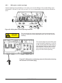
5.2
Display and Keypad
5.2.1
Components
(A) Display
(B) Keys
ESC
5.2.2
Display layout
Format
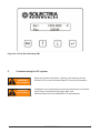
-------------------> D a t e :
DD.MM.YYYY
Time:
12h
The display has 4 rows of 20 characters each.
The first row contains the name of the currently displayed menu.
The second to fourth rows show the menu elements.
A small arrow in the third row shows the currently selected menu item.
46
DOCR 070366-B
5.2.3
Keypad
Symbol
Use
•
•
•
•
•
•
•
•
•
ESC
5.2.4
Exit the current menu
Cancel the setting of a value
Move upwards in a menu
Set a value (increase the value)
Move downwards in a menu
Set a value (decrease the value)
Select a menu entry
Open a configurable value for editing
Finish editing (adopt the set value)
General menu structure
The menus have up to three levels:
[Main menu]
...
400 Production info
410 Current data
411 Current overview
412 Current data AC
...
420 Day statistics
430 Week statistics
...
500 User settings
Most menu names consist of a three-digit number and a menu title.
See Section 12.3 Overview of menu structure” for an overview of the complete menu structure.
5.3
Inverter turn-on procedure
1. Refer to Section 5 for commissioning process that needs to be completed
before the inverter can begin feeding power to the grid.
2. Turn on the DC disconnect (put in closed position).
3. Check for inverter initialization; all 3 LED indicators are illuminated.
4. Unlock and turn on the dedicated 2-pole 240 Vac / 208 Vac circuit breaker in the
building electrical service panel.
5. Turn on the AC disconnect.
DOCR 070366-B
47
5.4
Inverter turn-off procedure
1. Turn off the AC disconnect.
2. Turn off the dedicated 2-pole 240 Vac / 208 Vac circuit breaker in the building
electrical service panel and lock it out.
3. Turn off the DC disconnect.
5.5
Standard initial commissioning
5.5.1
Brief overview of the commissioning steps
– Select the grid voltage configuration
– Set up the RS-485 communication
5.5.2
Detailed description of the commissioning steps
1.
Check all connections and cables for damage and correct seating. Correct the installation if
necessary.
2.
Switch on the DC disconnect
→ The startup process of the inverter begins.
After the startup process and the automatic self-test, the initial commissioning procedure of
the inverter starts and the Installation menu is displayed.
3.
Select a grid.
Grid Selection
-------------------> G r i d :
US 208 D
Continue
Grids available for standard commissioning
Display text
Description
US 208 D
US 208 DELTA 3 PHASE SYSTEM
US 208 WYE
US 208V/120V WYE 3 PHASE SYSTEM
US 240 D
US 240 DELTA 3 PHASE SYSTEM
US 240 STING
US 240/120 STINGER LEG 3 PHASE SYSTEM
US 240 SPLIT
US 240/120 SPLIT PHASE SYSTEM
48
DOCR 070366-B
4.
Select Continue and press the
key.
- G- r- i- d- - S- e- l- e- c- t- i- o- n- - - - Grid:
US 208 D
-> C o n t i n u e
------------------→ The RS-485 menu is displayed
5
Set the RS-485 ID and the baud rate.
RS485
-------------------> I D :
1
Baud Rate:
19200
Configurableparameters
Display text
Designation
Description
ID
RS-485 ID
1 .. 255
Baud rate
Baud rate
2400 | 4800 | 9600 | 19200 | 38400, the standard is
19200
NOTICE!
AVIS!
6.
Connecting multiple inverters via RS-485.
–
If multiple inverters are to be connected via
RS485, select a different ID for each inverter. This ID will
also be used later to identify each inverter when loading settings
or transferring data.
Select Continue and press the
key.
- - - - - - R- S- 4- 8- 5- - - - - - - - Baud Rate:
19200
-> C o n t i n u e
-------------------
1
–> The last menu is displayed
7
Press the
key to finish commissioning.
ENTER
to confirm
ESC
to reselection
Commissioning is now finished.
DOCR 070366-B
49
5.6
Setting values
You can set parameters in several menus. The
The
key increases the value of the parameter.
The
key decreases the value of the parameter.
keys are used to change parameter values.
The ESC key can be used to cancel the setting, and the original value is then displayed once more.
Pressing the
key causes the new parameter value to be adopted.
The example on the next page illustrates the procedure for changing the value of a parameter.
This procedure is the same for all configurable parameters.
Example: Setting the date
Keys
Action
Result
1. Press the
keys in the main
menu to select the Install settings
menu.
2. ..Press the
key to open the 100
Install settings (installation settings)
menu.
100 Install settings
-------------------> D a t e a n d t i m e
Display settings
3. ..Press the
key to open the 110
Date and time menu.
110 Date and time
Format
-> D a t e :
18/06/2013
Time:
13:10:20pm
4. Use the
menu item.
keys to select Date
110 Date and time
Format
-> D a t e :
18/06/2013
Time:
13:10:20pm
5. ..Press the
the setting.
key to begin making
110 Date and time
Format
-> D a t e :
1 8 / 0 6/ 2 0 1 3
Time:
13:10:20pm
→ The digits for the first value (in this
case the month) flash.
50
DOCR 070366-B
Keys
Action
6. Use the
7. Press the
value.
Result
keys to set the month.
key to adopt the new
→ The digits for the second value (in
this case the day) flash.
110 Date and time
Format
-> D a t e :
1 8 / 0 7/ 2 0 1 3
Time:
13:10:20pm
110 Date and time
Format
-> D a t e :
1 8/ 0 7 / 2 0 1 3
Time:
13:10:20pm
8. Use the
keys to set the day.
110 Date and time
Format
-> D a t e :
1 5/ 0 7 / 2 0 1 3
Time:
13:10:20pm
9. ..Press the
value..
key to adopt the new
110 Date and time
Format
-> D a t e :
1 5 / 0 7 /2 0 1 3
Time:
13:10:20pm
→ The digits for the last value (in this
case the year) flash.
10. Use the
keys to set the year.
11. ..Press the
value..
key to adopt the new
√ The value is adopted and the editing
mode is exited.
DOCR 070366-B
110 Date and time
Format
-> D a t e :
1 5 / 0 7 /2 0 1 4
Time:
13:10:20pm
110 Date and time
Format
-> D a t e :
15/07/2014
Time:
13:10:20pm
51
6
Production Information
NOTICE!
AVIS!
6.1
All energy production information is provided for informative purposes only. An accurate external revenue grade meter provided
by the wiring company is the authoritative source of information
for invoicing.
Overview
The 400 Production info menu contains current data and statistics. The information is write-protected and cannot be edited.
– Select the Production info menu item in the main menu.
→ The 400 Production info menu is displayed.
400 Production Info
-------------------> C u r r e n t D a t a
Day Statistics
Structure of the 400 Production info menu
Sub-menu
Content
Description
410 Current data
Current data for power, AC, PV,
insulation
“6.2 Current data”
420 Day statistics
Statistics for AC, PV and ISO
“6.3 Other statistics”
470 Feed-in
settings
Settings for currency and revenue
per kWh
“7.3 Grid feed-in settings”
480 Event journal
List of operating state messages
“8. Diagnosis and maintenance”
490 History
Statistics for the last seven days in
which the inverter was in operation.
“6.3 Other statistics”
430 Week statistics
440 Month statistics
450 Year statistics
460 Total statistics
52
DOCR 070366-B
6.2
Current Data
The current data values are provided in the menu 410 Current data.
Access
– Access the menu by navigating to Main menu > Production info > Current data.
→ The 410 Current data menu is displayed.
410 Current data
-------------------> C u r r e n t o v e r v i e w
Current data AC
Structure
Sub-menu
Contents and example display
411 Current overview
Current power and energy generation for the current day.
Current operating state (see “8. Diagnosis and maintenance”)
If there are messages, the list of messages can be opened by pressing the
key. For a detailed description, see chapter “8. Diagnosis
and maintenance”
412 Current data AC
Displays for: voltage, frequency, current, active power P, reactive
power Q
412 Current data AC
L1 Voltage:
_V
L1 Current:
_._A
L1 Freq.:
_.__Hz
416 Current data PV
Data for: voltage, current
416 Current data PV
PV1 Voltage:
PV1 Current:
---V
-.--A
DOCR 070366-B
53
Sub-menu
Contents and example display
41A Date and time
Shows the current date and time.
Use the 110 Date and time menu to set the values, see “7.2.1 Date
and time”.
41A Date and time
Date:
Time:
41B Current isolation
18/06/2013
10:20:30
Data for: maximum and minimum insulation resistances
41B Current isolat.
R iso+:
R iso-:
6.3
_kΩ
_ kΩ
Other statistics
Menu
420 Day statistics
430 Week statistics
440 Month statistics
450 Year statistics
460 Total statistics
490 History
Example display
420 Day statistics
Day stat. AC
-> D a y s t a t . P V
Day stat. ISO
The statistics for day, week, month, year and total production time all offer the same type of data.
The 490 History menu shows the statistics for the last seven days over which the inverter was in
operation.
54
DOCR 070366-B
490
Day:
-> D a y :
Day:
History
10.10.12
10.10.12
10.10.12
Structure
Sub-menu
Contents
421 Day stat. AC
Statistics for: total energy, runtime, revenue
431 Week stat. AC
Information on configuring the revenue settings is provided in “7.3
Grid feed-in settings”.
441 Month stat. AC
451 Year stat. AC
461 Total stat. AC
Displays for:
Δf Minimum/maximum frequency
Imax Maximum current
ΔU Minimum/maximum voltage
Pmax Maximum active power
Qmax Maximum reactive power
Qmin Minimum reactive power
421 Day stat. AC
L1 Δf: --.--/--.--Hz
L1 Imax:
--.--A
L1 ΔU:
---/---V
422 Day stat. DC
Displays for:
432 Week stat. DC
Pmax Maximum power
442 Month stat. DC
Imax Maximum current
452 Year stat. DC
Umax Maximum voltage
462 Total stat. DC
422
PV1
PV1
PV1
Day stat. DC
Imax:
_._A
Umax:
_V
Pmax:
_W
DOCR 070366-B
55
Sub-menu
Contents
423 Day stat. ISO
Statistics for: maximum/minimum insulation resistances
433 Week stat. ISO
443 Month stat. ISO
453 Year stat. ISO
463 Total stat. ISO
Pmax Maximum power
Imax Maximum current
423 Day stat. ISO
R ISO max:
R ISO min:
491 ... 497 Day ...
----kΩ
- - - - kΩ
Statistics for the last 7 days in which the inverter was in operation.
The statistics contain the same information as the menus 421, 422
and 423.
491 Day
Energy:
Runtime:
Revenue:
6.4
18.06.2013
----Wh
-:--h
--.--USD
Deleting statistics
Description
All statistics can be deleted (except for 410 Current data). The procedure is always the same.
1.
Navigate to Production info > Feed-in settings > statistics.
→ The 471 statistics menu is displayed.
471
Reset
Reset
Reset
->
2.
Use the
press the
Statistics
day stat.
week stat.
month stat.
keys to select the statistic you wish to delete (e.g., Reset day stat.) and
key.
→ A confirmation query is displayed.
56
DOCR 070366-B
3.
Select the option Yes and press the
key to delete the statistic.
Reset day stat.
------------------No
-> Y e s
→ A confirmation message is displayed.
Reset day stat.
Successful
Press Enter
The statistic for the day is deleted.
7
Settings
7.1
Overview
This chapter describes how to edit the configurable settings.
•
Installation settings (Section 7.2 Installation settings”)
•
Grid feed-in settings (Section 7.3 Grid feed-in settings”)
•
Options settings (Section 7.4 Options settings”)
•
Standard menu (Section 7.5 Standard menu”)
Information on operating the display is provided in Section 5.2 Display and keypad”.
7.2
Installation settings
Configurablesettings
•
Date, time
•
Date and time format
•
Contrast
•
Grid configuration selection
•
RS-485 settings
DOCR 070366-B
57
7.2.1
Date and time
Description
Menu
110 Date and time
Menu access
Main menu > Install settings > Date and time
Example display
110 Date and time
Format
-> D a t e :
18/06/2013
Time:
13:10:20pm
Configurableparameters
Display text
Designation
Date
Date
Time
Time
7.2.2
Description
Feedly configurable according to the selected date
format.
Feedly configurable according to the selected time
format.
Date and time formats
Description
Menu
111 Format
Menu access
Main menu > Install settings > Date and time > Format
Example display
111 Format
->
Date:
Time:
DD/MM/YYYY
13:10:20pm
Configurableparameters
Display text
Designation
Description
Date
Date format
DD.MM.YYYY
DD/MM/YYYY
DD-MM-YYYY
Time
58
12h | 24h
DOCR 070366-B
7.2.3
Contrast
Description
Menu
120 Display settings
Menu access
Main menu > Install settings > Display settings
Example display
Configurableparameters
Display text
Designation
Description
Contrast
Display Contrast
5...10
7.2.4
Grid selection
DANGER!
DANGER!
NOTICE!
AVIS!
If the selected grid is changed, a completely new commissioning
process must be started, see Section 5. Commissioning the PV
system”.
Always first contact the Solectria Support Team before changing
the selected grid!
You always require a PIN in order to enter the grid selection mode.
You require a new PIN each time you wish to select a new grid
configuration. You obtain a key for the PIN from the Solectria Support Team on request.
You must provide a key in order to receive a PIN. You will find the key in the menu 132 Grid
change.
1.
To display the key, navigate to Main menu > Install settings > Grid selection> Grid
change.
132 Grid change
Grid:
US 208 D
Key:
###########
PIN: ____ Confirm
DOCR 070366-B
59
The key consists of 11 numbers and letters.
2.
The Solectria Support Team will provide you with the four digit PIN.
3.
When you have received the PIN, navigate to the menu 132 Grid change and press the
key.
→ The first digit of the PIN flashes.
4.
Use the
keys to set the first digit and press the
key to proceed to the next digit.
→ After entering the full PIN, the word Confirm flashes.
132 Grid change
Grid:
US 208 D
Key:
###########
PIN: 1234 Confirm
5.
Press the
key to confirm the entered PIN.
→ The Installation menu is displayed.
Installation
-------------------> L a n g u a g e :
English
continue
6.
Start the commissioning of the inverter, see “5. Commissioning the PV system”.
7.2.5
RS-485
Description
Menu
111 Format
Menu access
Main menu > Install settings > RS-485
Example display
140 RS485
-------------------> I D :
1
Baud rate:
19200
60
DOCR 070366-B
Configurableparameters
Display text
Designation
Description
ID
RS-485 ID
1...255
Baud rate
Baud rate
2400 | 4800 | 9600 | 19200 | 38400, the standard
is 19200
Connecting multiple inverters via RS-485.
NOTICE!
► Select a different ID for each inverter.
► A 220 ohm termination resistor must be connected to the last
inverter in the series (see “4.8.7 Inverter RS-485 Communication
Connections”).
AVIS!
NOTICE!
AVIS!
7.3
NOTICE: An optional full-featured inverter direct data acquisition and
logging gateway and web-based service, SolrenView, is available from Solectria Renewables (http://www.solrenview.com). The
gateway allows the inverter to deliver information to the SolrenView
server through the facility‘s internet service.
Grid feed-in settings
Description
Menu
470 Feed-in settings
Menu access
Main menu > Production info> Feed-in settings
Example display
Configurableparameters
Display text
Designation
Description
Currency
Currency
No pre-defined values.
USD / kWh
USD/kWh
No pre-defined values. The amount (USD) per
kWh is required for the revenue calculation.
DOCR 070366-B
61
7.4
Options settings
Configurablesettings
•
•
•
•
Shading
AFCI setting
AFCI self test
Arc fault clear
7.4.1
Shading
Description
The “Shading“ option is an extended MPP tracker. When the option is switched on, the MPP
tracker performs an additional search at regular intervals.
The MPP tracker then searches for the maximum power over a wider voltage range.
This option should be switched on if shadows regularly pass slowly over the PV modules in
the course of a day. These types of moving shadows can be caused by chimneys or trees, for
example. Do NOT use this option for normal fast-moving shadows, e.g., from passing clouds.
The option is set depending on the size of the shading.
Menu
210 Shading
Menu access
Main menu > Options > Shading
Example display
Configurableparameters
Display text
Designation
Description
Mode
Mode
Disabled
Extended MPP tracking is disabled
High
High shading, time cycle: 0.5 hours
Medium
Medium shading, time cycle: 2 hours
Low
Low shading, time cycle: 4.5 hours
62
DOCR 070366-B
7.4.2
AFCI setting
If the AFCI setting is changed, a completely new commissioning
process will need to be started, see “5. Commissioning the PV
system”.
A PIN is required each time you wish to change the AFCI setting.
You can obtain a PIN from the Solectria Customer Service Team
upon request.
You must provide a key in order to receive a PIN. You will find the key in the menu 230 AFCI
Setting.
1.
To display the key, navigate to Main menu > Options > AFCI Setting.
The key consists of 11 numbers and/or letters.
2.
The Solectria Customer Service Team will provide you with the four digit PIN.
3.
When you have received the PIN, navigate to the menu 230 AFCI Setting and press the
button.
→ The first digit of the PIN flashes.
4.
Use the
digit.
buttons to set the first digit and press the
button to proceed to the next
→ After entering the full PIN, the word Confirm will flash.
5.
Press the
button to confirm the entered PIN.
→ The AFCI Setting menu is displayed. You can enable or disable the arc detection
function through it.
6.
Start the commissioning of the solar power inverter, see “5. Commissioning the PV system”.
DOCR 070366-B
63
7.4.3
AFCI self test
Description
The “AFCI Self Test” is a manual test function. When “enabled,”a self test of the arc detection
function will be carried out. If the internal circuit is OK, the inverter will show “AFCI Test Pass!” on
the display and shut down once the test passes. The inverter will start up again after the self test.
1.
To display the arc self test, navigate to Main menu > Options > AFCI Self Test.
2.
To enable the AFCI self test, change the mode from “disabled” to “enabled”. When the test
passes, the mode will change back to “disabled”. The inverter will be shut down.
3.
The inverter will restart. The operation mode will show “normal operation” again.
7.4.4
Arc fault clear
Description
When an arc fault occurs, the inverter will shut down and the “Arc Fault Detected!” message will
be displayed. The inverter will remain off until the arc fault is cleared manually.
1.
Check the operation mode of the inverter, navigate to Main menu > Production info >
Current data > Current overview. If an arc fault occurs “Arc Fault Detected!” will be displayed.
2.
64
To clear the arc fault status, navigate to Main menu > Options > Clear Arc Fault
DOCR 070366-B
3.
Select “Yes“ and press the
4.
Press the
7.5
button.
button. The display page will go back. The inverter will start up.
Standard menu
Description
A standard menu can be defined, which is automatically displayed when the display keys are
not used for a certain period of time. When the standard menu is displayed, pressing the ESC key
displays the main menu.
The standard menu is set to 411 Current data at the factory. This menu shows the current data
and current operating messages.
The number must be a valid menu number.
See “12.3 Overview of menu structure” for an overview of all available menu numbers.
1.
Press the
key to enter the menu number.
→ The first digit flashes.
2.
Enter the first digit of the menu number using the
keys.
→ You can only set menu numbers that actually exist. The name of the associated menu is
displayed in the fourth display row.
3.
Once you have set the first digit, press the
key.
→ The second digit flashes.
4.
Enter the second and third digit in the same manner.
5.
Press the
key.
→ The menu corresponding to the entered menu number is displayed.
Menu
800 Standard
Menu access
Main menu > Standard
Example display
DOCR 070366-B
65
Configurableparameters
Display text
Designation
Description
Menu number
Menu number
Any valid menu number.
8
Diagnosis and maintenance
8.1
Operating states
8.1.1
Types of operating states
Operating state
Associatedinfluencing
factors
Normal operation
No factors are present that limit
Yes
the energy production results.
Limited operation
Non-critical factors that can
affect the energy production but
Limited
which are not equipment or system failures (e.g., self-test).
Warning
Failure
External events or internal
failures are present that affect
the production results.
Insulation or
grounding failure
A problem exists with the
insulation
Grid feed-in
Yes
No
No
See section 8.1.2 for a description of the influencing factors.
Note: When in failure mode, the inverter will not produce power.
8.1.2
Factorsinfluencingtheoperatingstate
Different influencing factors are assigned to the individual operating states. These influencing
factors are divided into the following categories.
Non-critical factors
Non-critical factors are (for example) the self-test or a DC voltage that is too low due to bad weather. Non-critical factors are therefore not failures.
Events
Events are usually caused outside the inverter. Events are divided into external events (e.g., voltage or frequency errors) and parameter changes occurring via the keys or the RS-485 interface.
Internal failures
Internal failures are caused from within the inverter and must be corrected with help of the Solectria Support Team.
66
DOCR 070366-B
Insulation and grounding failures
Insulation and grounding failures are logged and displayed when this failure occurs. When an
insulation or graounding failure is indicated, the failure has to be corrected by the installer before
the inverter will restore power production.
8.1.3
Display of the current operating state
The actual operating state is indicated via LEDs. A short message is also shown in the fourth line
of the 411 Current overview menu.
The 411 Current overview menu is automatically displayed when a new message arrives.
LED status
Green
<ON>
Red
<OFF>
Yellow
<OFF>
Green
<ON>
Red
<OFF>
Yellow
<OFF>
Green
<ON>
Red
<OFF>
Yellow
<Flash>
Green
<OFF>
Red
<OFF>
Yellow
<ON>
Green
<OFF>
Red
<ON>
Yellow
<OFF>
Message category Display text in menu 411
Normal operation
Normal operation
Limited operation
e.g. Self-test
General warning
messages
For external events: External events
For internal failures: Warning ### (3-digit
number)
General failure
messages
For external events: External events
For internal failures: Failure ### (3-digit
number)
Insulation or
grounding failure
Insulation
The software defines which events trigger a warning and which events trigger a failure.
DOCR 070366-B
67
8.2
Event log
8.2.1
Overview
Menu
480 Event journal
Menu access
Main menu > Production info> Event journal
Example display
480 Event journal
-------------------> E x t e r n a l e v e n t s
Change events
The event journal contains the messages relating to the following events:
•
Parameter changes - Changes to all parameters influencing the energy production and
therefore the revenue production.
•
External events - Problems with the insulation and grounding
Sub-menu
Description
481 External events A list of all external events.
482 Change events
8.2.2
A list of parameter changes made via the display or via RS-485.
External events menu
Description
Menu
481 External events
Menu access
Main menu > Production info> Event journal > External events
Example display
481 External events
18.06.2013 17:29:56
L1 Islanding
Begin
The external event message has the following structure:
2nd line
Date and time when the external event occurred..
3rd line
Short description of the failure (see chapter "8.3 Troubleshooting and
correction")
4th line
Additional information, e.g., "Begin" for the occurrence of an event or
"End" for the disappearance of an event.
68
DOCR 070366-B
8.2.3
Change events menu
Description
The 482 Change events menu contains a chronological list of all changes to parameters influencing the energy production and thus also the revenue.
Menu
482 Change events
Menu access
Main menu > Production info> Event journal > Change events
Example display
482 Change events
18.06.13 17:29:56 D
Max. power:
100%
Max. power:
90%
The parameter change entry has the following structure:
Menu
482 Change events
2nd line
Date and time when the external event occurred.
Source of the change:
D: Display
E: External (RS-485)
S: System
3rd line
Name of the changed parameter + previous value
4th line
Name of the changed parameter + new value
DOCR 070366-B
69
8.3
Troubleshooting and correction
8.3.1
External events / Insulation and grounding failures
The 411 Current overview menu shows one of the following messages:
411 Current overview
Now:
-W
Day:
0Wh
External events
411 Current overview
Now:
-W
Day:
0Wh
Insulation
1.
To receive a more exact description of the problem, press the
411 Current overview menu.
key in the
→ The External events menu is displayed.
External events
PV1 ISO running fail
PV1 ISO startup fail
------------------The menu contains a list of all active messages relating to external events and insulation/grounding.
2
press the
key again.
→ The 480 Event journal menu containing the detailed message text is displayed
(see "8.2 Event journal").
480 Event journal
-------------------> E x t e r n a l e v e n t s
Change events
3
Select the entry External events and press the
key again.
480 Event journal
-------------------> E x t e r n a l e v e n t s
Change events
70
DOCR 070366-B
→ The 481 External events menu is displayed.
481 External events
18.06.2013 17:29:56
L1 Islanding
Begin
Alternatively, you can also directly open the 483 External events menu via the “Go to menu“
function, see chapter "12.3.1 ‘Go to menu‘ function".
The following table shows the failure messages that can appear in the 483 External events menu
and provides troubleshooting and correction suggestions.
LED Status
Display message
Message description Fault correction
Warning ###
Internal failure ("Warning" + three-digit number)
Green
<ON>
Red
<OFF>
Yellow
<Flash>
Green
<OFF>
Red
<OFF>
Yellow
<ON>
Green
<OFF>
L1 Voltage
AC overvoltage or undervoltage on phase L.
Red
<OFF>
failure
► Check the grid voltage shown on the display (menu
412 Current data AC).
Yellow
<ON>
Green
<OFF>
L1 Frequency
AC high frequency or low frequency on phase L.
Red
<OFF>
error
► Check the grid frequency shown on the display
(menu 412 Current data AC).
Yellow
<ON>
Green
<OFF>
Red
<OFF>
► Ask your electricity supply company about the
actual state of the grid.
Yellow
<ON>
► Check the installation.
► Please contact Delta Support.
Failure ###
Internal failure ("Failure" + three-digit number)
► Please contact Delta Support.
► If no voltage is present, check the circuit breaker.
► If no voltage is present, check the automatic circuit
breaker.
L1 Islanding
Frequency shift failure on phase L.
► Restart the solar power inverter. Contain your
maintenance technician if the failure persists.
Green
<OFF>
PV Power too low The solar power is too low.
Red
<OFF>
Insufficient solar irradiation (dawn/dusk)..
Yellow
<ON>
► Check the PV cell voltage shown on the display
(menu 416 Current data PV).
DOCR 070366-B
71
LED Status
Display message
Message description Fault correction
Green
<OFF>
PV1 ISO startup
The startup insulation is too low.
Red
<ON>
fail
Yellow
<OFF>
► Check the insulation resistance at the DC side of
the PV modules.
Green
<OFF>
PV1 ISO running
Residual current excess the safety standard.
Red
<ON>
fail
Yellow
<OFF>
► Check the insulation resistance at the DC side of
the PV modules.
8.3.2
Internal failures
In the case of an internal failure, the message "Warning XXX" or "Failure XXX" is displayed in the
411 Current overview menu. XXX stands for a 3-digit failure number.
411 Current data
L1
_W
Day:
_Wh
Warning 123
411 Current data
L1
_W
Day:
_Wh
Failure 351
In the case of internal failures, always contact the Solectria Support Team (see address list on the
rear cover of this manual).
72
DOCR 070366-B
8.3.3
Other LED and display messages
LED Status
Display message
Message description Fault correction
PV1 Voltage too
low
The PV1 voltage is too low.
Green
<Flash>
Red
<OFF>
Yellow
<OFF>
Green
<ON>
L1 Power
reduction
Power reduction activefor L1.
Red
<OFF>
PV1 PW limit
to Pn
Power limiting active for PV1.
Yellow
<OFF>
PV1 Temp
derating
Temperature derating active for PV1. Reduced
electricity production.
There is insufficient solar irradiation.
► Check the PV cell voltage shown on the display
(menu 416 Current data PV).
The internal temperature of the solar power
inverter lies between +45 and +70 °C.
► Check the ventilation of the solar power
inverter.
► Prevent direct sunlight from reaching the solar
power inverter.
8.4
Displaying grid settings
Description
The actual grid settings can be displayed using the 131 View grid setup menu. The contents of
this menu are write-protected.
Menu
131 View grid setup
Menu access
Main menu > Install settings >Grid selection> View grid setup
Example display
131 View grid setup
->
Grid:
Fnom:
US 208 D
--.--Hz
If a power limit was set when the inverter was commissioned, then the following message is displayed before the menu opens:
DOCR 070366-B
73
8.5
Internal log
Description
The internal log contains information on the internal failures that have occurred.
Menu
620 Internal log
Menu access
Main menu > Diagnostic&Alarm > Internal log
Example display
620 Internal log
12.04.12
126 127
7:39:25
Parameter change entries have the following structure:
3rd Line
Date and time when the external event occurred.
4th Line
Number(s) of the internal failure(s)
8.6
Maintenance
DANGER!
DANGER!
Lethal danger from hazardous voltage.
Hazardous voltage exists while the inverter is operating. Hazardous voltage may still be present 5 minutes after all power sources
have been disconnected.
► Never open the inverter. The inverter contains no components that are user serviceable. Opening the cover will void the
warranty.
Ensure that the inverter is not covered and has sufficient air flow during operation.
Regularly clean the inverter to prevent soiling of the enclosure.
9
Repair
DANGER!
DANGER!
74
Danger of death from hazardous voltage.
Hazardous voltage exists while the inverter is operating. Hazardous voltage may still be present 5 minutes after all power sources
have been disconnected.
► Never open the inverter. The inverter contains no components that are user serviceable. Opening the cover will void the
warranty.
DOCR 070366-B
NOTICE!
The inverter contains no components that are user serviceable.
AVIS!
10
Removal, transport, storage, disposal
DANGER!
DANGER!
DANGER!
DANGER!
WARNING!
AVERTISSEMENT!
10.1
Danger of death or severe injuries from dangerous voltage
► Disconnect the inverter from the AC grid before removing
the AC conductors.
► Verify absence of AC voltage before removing conductors.
Danger of death or severe injuries from dangerous voltage
Dangerous voltages can be present at the DC connections of the
inverter.
► Never disconnect the PV modules when the inverter is connected to AC grid or DC disconnect is on. First switch off the AC
conductors grid so that the inverter cannot feed energy into the
grid. Then, open the DC disconnect.
► Verify absence of DC voltage before removing conductors.
Danger of injury due to heavy weight
The inverter is heavy (see “11. Techical Data”, p. 71). Incorrect
handling can lead to injuries.
► The inverter must be lifted and carried by two people.
Removal
1. Switch off the AC breaker and verify absense of AC voltage.
2. Open the DC disconnect, verify the absense of DC voltage on both the inverter
and array sides, then disconnect PV array.
3. Remove DC and AC conductors and conduits from the inverter.
4. Unscrew the inverter from the wall bracket.
5. Lift the inverter from the wall bracket.
10.2
Transport
Always transport the inverter in the original packaging or packaging of the same quality.
10.3
Storage
Always store the inverter in the original packaging or packaging of the same quality. Observe the
specifications relating to storage conditions described in Section 11: “Technical data”.
10.4
Disposal
Dispose of the inverter in an appropriate manner according to the legal requirements of your
country, state and municipality.
DOCR 070366-B
75
11
Technical data
INPUT (DC)
PVI 3800TL
PVI 5200TL
PVI 6600TL
PVI 7600TL
Max. recommended
PV power
4580 WP
6200 WP
8000 WP
9100 WP
18 A per MPP tracker
20 A per MPP tracker
Max. System
Voltage
600 V
Operational
Voltage range
120 ... 550 V
Full powerr MPP
range
200... 500 V
Max. current
20 A
Max. allowed
imbalance power
15 A per MPP tracker
30% / 70%1)
-
DC disconnect
MPP tracker
Internal
1
2
MPP efficiency
2
2
99.5%, dynamic
OUTPUT (AC)
PVI 3800TL
PVI 5200TL
PVI 6600TL
PVI 7600TL
Nominal power
3800 W
5200 W
6600 W
7600 W
3300 W @ 208 V /
3800 W @ 240 V
5200 W @ 208 V /
5200 W @ 240 V
6600 W @ 208 V /
6600 W @ 240 V
6600 W @ 208 V /
7600 W @ 240 V
Max. power2)
Voltage range
Nominal current
Max. current
-12%/+10%
15.8 A @ 208 V /
15.8 A @ 240 V
25 A @ 208 V /
21.6 A @ 240 V
31.7 A @ 208 V /
27.5 A @ 240 V
31.7 A @ 208 V /
31.7 A @ 240 V
16 A
25 A
32 A
32 A
Nominal frequency
60 Hz
Frequency range
59.3-60.5 Hz
Night consumption
<2W
Total harmonic
distortion
@ norminal power
< 3%
Power factor @
norminal power
Max. output overcurrent protection
Reactive power
capability
76
Unity, >0.99
56A3)
28A
Yes
DOCR 070366-B
GENERAL
SPECIFICATION
PVI 3800TL
PVI 5200TL
PVI 6600TL
Max efficiency
98.0%
CEC efficiency
97.5% @ 208V /
97.5% @ 240V
Operating
temperature
-13 to +158 °F (-25 to +70 °C) /
Derate above 122 °F (50 °C)
-40 to +185 °F
(-40 to +85 °C)
Storage temp.
Humidity
0 ... 100%
Max operating
altitude
MECHANICAL
DESIGN
Dimensions
L x W x D inches
(L x W x D) mm
Weight
Cooling
2000 m above sea level
PVI 3800TL
PVI 5200TL
PVI 6600TL
17.5 x 15.8 x 8.5 in.
(445 x 401 x 216)
26.8 x 15.8 x 8.5 in.
(680 x 401 x 216 mm)
43 lbs (19.5 kg)
65 lbs. (29.5 kg)
Screw terminals in connection box
DC connectors
Screw terminals in connection box
Communication
interface
RS-485
Enclosure material
PVI 7600TL
Convection
AC connectors
Display
PVI 7600TL
3 LEDs, 4-line LCD
Aluminum
1) Un-balanced PV input allowed, maximum input power for each MPP tracker is limited with 70% rating power and total input
is limited with 100% rating power.
2) The maximum AC power value indicates the power an inverter might be able to deliver, but such a maximum AC power
may not necessarily be achieved.
3) Max. output fault current and duration is 140Apk, 2ms duration@208V, 116.8Apk, 6.15ms duration@240V.
DOCR 070366-B
77
STANDARDS /
DIRECTIVES
PVI 3800TL
PVI 5200TL
Electronics
protection rating
PVI 6600TL
PVI 7600TL
NEMA 4, IEC 60068-2-11 (Salt mist)
Safety
UL 1741, CSA 22.2 No. 107-01
SW Approval
UL 1998
Isolation Monitor
Interrupt (IMI)
NEC 690.35, UL1741 CRD
Unintentional
Islanding protection
IEEE 1547, IEEE 1547.1
EMC
FCC part 15 A & B, ICES-003
AFCI
UL1699B (Type 1), NEC 690 2014
WARRANTY
PVI 3800TL
PVI 5200TL
PVI 6600TL
Standard warranty
10 years
Extended warranty
By request (15 or 20 year options)
PVI 7600TL
Utility interconnection voltage and frequency trip limits and trip times for all models:
Simulated utility source
Voltage (V)
Frequency (Hz)
Maximum time (sec) at 60Hz
before cessation of current to the
simulated utility
< 50% V
Rated (60 Hz)
0.16
50% V ≤ V > 88% V
Rated (60 Hz)
2
110% V < V < 120% V
Rated (60 Hz)
1
120% V ≤ V
Rated (60 Hz)
0.16
Rated
f > 60.5
0.16
Rated
f > 59.3
0.16
Trip limit and trip time accuracy for all models:
±1 V (L-L)
Voltage:
Frequency:
Time:
78
±0.01Hz
1%, but not less than 100ms
DOCR 070366-B
11.1
FCC Compliance Information
SOLECTRIA RENEWABLES, LLC. string inverters, Model PVI 3800TL, PVI 5200TL, PVI 6600TL
and PVI 7600TL.
This device complies with Part 15 of the FCC Rules. Operation is subject to the following conditions:
(1) This device may not cause harmful interference, and
(2) This device must accept any interference, including interference that may cause undesired
operation.
Note: This equipment has been tested and found to comply with the limits for a Class B digital
device, pursuant to part 15 of the FCC Rules. These limits are designed to provide reasonable
protection against harmful interference in a residential installation. This equipment generates,
uses and can radiate radio frequency energy and, if not installed and used in accordance with
the instructions, may cause harmful interference to radio communications. However, there is no
guarantee that interference will not occur in a particular installation. If this equipment does cause
harmful interference to radio or television reception, which can be determined by turning the
equipment off and on, the user is encouraged to try to correct the interference by one or more of
the following measures:
•
•
•
•
•
Reorient or relocate the receiving antenna
Increase the separation between the equipment and the receiver
Connect the equipment into an outlet on a circuit different from that to which the receiver is
connected.
Consult the dealer or an experienced radio/TV technician for help.
The user is cautioned that changes or modifications not expressly approved by SOLECTRIA
RENEWABLES could void the user‘s authority to operate this equipment.
Contact SOLECTRIA RENEWABLES for more information:
SOLECTRIA RENEWABLES
360 Merrimack Street
Building 9, Floor 2
Lawrence, MA 01843
U.S.A
http://www.solren.com/products-and-services/grid-tied-solar-inverters/residential/pvi3800-7600TL-solar-inverter
Support Email: [email protected]
Support Hotline: 978-683-9700
11.2
Canadian Compliance Information
This Class B digital apparatus complies with Canadian ICES-003.
DOCR 070366-B
79
12
Appendix
12.1
Overview of setting options
The following table contains an overview of all settings that can be made in the inverter.
Function /
Characteristic
Short description
Menu Manual chapter
200 Options
“7.4 Options settings”
Options
Shading
For setting up the extended MPP 210 Shading
tracking
“7.4.1 Shading”
Display settings
Date and time
For setting the date and time
110 Date and time
“7.2.1 Date and time”
Date and time
format
For setting the date and time
formats
111 Format
“7.2.2 Date and time formats”
Contrast
For setting the contrast
120 Display settings
“7.2.3 Contrast”
Standard menu
For selecting the display to be
shown when no key has been
pressed for a certain period of
time.
800 Standard
“7.5 Standard menu”
Monitoring
RS-485 settings
For setting the RS-485 ID and
the baud rate and for switching
the termination resistor on and
off
150 RS-485
“7.2.5 RS-485”
Showing statistics
Showing statistics
on the display
-
400 Production info
“6. Production information”
For setting the currency and the
revenue per kWh
471 Feed-in settings
“7.3 Grid feed-in settings”
Feed-in settings
Currency, revenue
per kWh
80
DOCR 070366-B
12.2
Order numbers
RS-485 cable
RS-485 connection cable
Cable for connecting inverters
Please contact Solectria for available options.
12.3
Overview of menu structure
12.3.1
"Go to menu" function
NOTICE!
AVIS!
1.
You can use the “Go to menu” function to directly navigate to a
particular menu.
To open the Go to menu function, press and hold the ESC key on the inverter for at least 3
seconds.
→ Go to menu opens.
Go to menu
-------------------> M e n u :
000
2.
Press the
key to enter the menu number.
→ The first digit flashes.
3.
Enter the first digit of the menu number using the keys. Press the
are finished.
key when you
→ The second digit flashes.
4.
Enter the second and third digit in the same manner.
5.
Press the
key.
→ The menu corresponding to the entered menu number is displayed.
DOCR 070366-B
81
12.3.2
Installation settings (100)
100 Installation
Explanation
130 Grid selection
Display the grid settings, change the grid
140 RS-485
Change RS-485 settings
110 Date and time
Explanation
Date:
18/06/2013
Date
Time:
15:12:23
Time
111 Format
Date and time formats
111 Format
Explanation
Date:
DD/MM/YYYY
Date format
Time:
24h
Time format (12h or 24h)
120 Display settings
Contrast:
Explanation
10
1...10
130 Grid selection
Explanation
131 View grid setup
Actual grid settings
132 Grid change
Set a different grid
140 RS-485
Explanation
ID:
Baud rate:
82
---
If multiple inverters are connected via RS-485,
then each inverter must have a different ID. (1
... 254)
Baud rate (2400 / 4800 / 9600 / 19200 / 38400)
DOCR 070366-B
12.3.3
Shading (210)
Mode
Explanation
Disable
Monitoring is deactivated.
High
High shading, time cycle: 0.5 hours
Medium
Medium shading, time cycle: 2 hours
Low
Low shading, time cycle: 4.5 hours
210 Shading
Explanation
Mode
12.3.4
Disable
Disabled / High / Medium / Low
Production information (400)
400 Production info
Explanation
410 Current data
Current power and energy values. Messages
on the current operating status.
420 Day statistics
Statistics for the current day
430 Week statistics
Statistics for the current calendar week
440 Month statistics
Statistics for the current calendar month
450 Year statistics
Statistics for the current calendar year
460 Total statistics
Statistics for the entire operating period
470 Feed-in settings
Settings for currency and revenue per kWh
480 Event journal
Messages off events
490 History
Power and energy value of latest 7 days
410 Current data
Explanation
411 Current overview
Current status
412 Current data AC
AC = AC side
416 Current data PV
PV = module side
41A Date and time
Date and time
41B Current insulation
Insulation resistance value
DOCR 070366-B
83
411 Current overview
Explanation
Now:
200W
Current active power
Day:
2000Wh
Energy production current day
Normal operation
Current status messages
412 Current data AC
Explanation
L1 voltage:
---V
Voltage
L1 Freq.:
--.--Hz
Frequency
L1 Current:
-.--A
Phase current
L1 P:
---W
Active power
L1 Q:
---Var
Apparent power
L1 DC inj.:
---mA
Feed-in current
416 Current data PV
Explanation
PV1 Voltage:
---V
Voltage on the PV side
PV1 Current:
-.--A
Current on the PV side
41A Date and time
Explanation
Date:
18.06.2013
Current date
Time:
15:05:19
Current time
41B Current insulation
R iso:
84
Explanation
----kΩ
Insulation resistance at DC+
DOCR 070366-B
420 Day statistics
Explanation
421 Day statistics AC
AC = AC side
422 Day statistics DC
DC = DC side
423 Day statistics ISO
ISO = Insulation
430 Week statistics
440 Month statistics
450 Year statistics
460 Total statistics
470 Feed-in settings
480 Event journal
490 History
421 Day statistics AC
Explanation
Energy:
---Wh
Energy
Runtime:
-:--h
Runtime
Revenue:
---USD
Revenue
L1 Imax:
-.--A
Maximum current
L1 Pmax:
---W
Maximum active power
L1 Qmax:
---Var
Maximum apparent power
L1 Qmin:
---Var
Minimum apparent power
431 Week statistics AC
441 Month statistics AC
451 Year statistics AC
461 Total statistics AC
DOCR 070366-B
85
491 Day
Explanation
Energy:
---Wh
Energy
Runtime:
-:--h
Runtime
Revenue:
---USD
Revenue
L1 Imax:
-.--A
Maximum current
L1 Pmax:
---W
Maximum active power
L1 Qmax:
---Var
Maximum apparent power
L1 Qmin:
---Var
Minimum apparent power
492 Day
493 Day
494 Day
495 Day
496 Day
497 Day
422 Day statistics DC
Explanation
PV1 Imax:
---A
Max. current
PV1 Umax:
---V
Max. voltage
PV1 Pmax:
---W
Max. power
432 Week statistics DC
442 Month statistics DC
452 Year statistics DC
462 Total statistics DC
86
DOCR 070366-B
423 Day statistics ISO
Explanation
R ISO max:
---kΩ
Max. insulation resistance
R ISO min:
---kΩ
Min. insulation resistance
433 Week statistics ISO
443 Month statistics ISO
453 Year statistics ISO
463 Total statistics ISO
470 Feed-in settings
Explanation
Currency
USD
Define the currency
USD / kWh:
#.##
Define the revenue pro kWh
480 Event journal
Explanation
481 External events
Overview of all external events and insulation/
grounding problems
482 Change events
Overview of all parameter changes
12.3.5
Diagnostics and Alarms (600)
The reports that are displayed depend on the grid configuration:
•
Internal log (is always displayed)
600 Diagnostic&Alarm
Explanation
620 Internal log
Firmware update
13.3.6
Software version/inverter data (700)
700 Inverter info
Explanation
710 Software vers.
Version of the installed software
720 Inverter data
Production date and serial number
DOCR 070366-B
87
12.3.7
Standard menu (800)
800 Standard menu
Explanation
Menu number:
Number of the menu that is to be displayed as
the standard menu.
88
DOCR 070366-B
13
Glossary
AC
Abbreviation for “Alternating Current”.
AHJ
Abbreviation for “Authority Having Jurisdiction” (electrical inspector).
Basic Insulation
Insulation to provide basic protection against electric shock.
CEC
Abbreviation for the California Energy Commission
CECEfficiency
CEC Efficiency is the California Energy Commission Efficiency rating, a performance rating for
modules and inverters based on the real environment that a system will be in.
CSA
Abbreviation for the Canadian Standards Association.
DC
Abbreviation for “Direct Current”.
EMC
The Electro-Magnetic Compatibility (EMC) concerns the technical of the mutual influencing of electrical devices through electromagnetic fields caused by them.
FCC
Federal Communications Commission.
Galvanic isolation
No conductive connection between two component parts.
GEC
Grounding Electrode Conductor
GET
Grounding Electrode Terminal
IEEE
The Institute of Electrical and Electronics Engineers or IEEE is an international non-profit, professional organization for the advancement of technology related to electricity.
IMI
Isolation Monitor Interrupter
ISC
Short Circuit Current
Local utility company
A local utility company is a company that distributes electricity over the grid.
DOCR 070366-B
89
MPP
The Maximum Power Point is the point on the current-voltage (I-V) curve of an array or string, where
the product of current and voltage has it’s maximum value.
NEC
The National Electrical Code (NEC), or NFPA 70, is a United States standard for the safe installation
of electrical wiring and equipment.
Power dissipation
Power dissipation is designated as the difference between absorbed power and power of a device
or process yielded. Power dissipation is released mainly as heat.
PV cell
PV cells are large-surface photodiodes which convert light energy (generally sunlight) into electrical
energy. This comes about by utilization of the photoelectric effect (photovoltaics).
PV array
System comprising of a number of PV modules.
PV module
Part of a PV generator; converts PV energy into electrical energy.
RJ-45
Abbreviation for standardized eight-pole electrical connector connection. RJ stands for Registered
Jack (standardized socket).
RS-485 (EIA485)
Differential voltage interface on which the genuine signal is transmitted on one core and the negated (or negative) signal on the other core.
Inverter
is an electrical device which converts DC direct voltage into AC voltage and/or direct current into
alternating current.
String
Designates a group of electrical PV modules ammended in series.
UL
Stands for Underwriters Laboratory, an organization that sets standards for different product categories and tests products to make sure they meet the standards.
VOC
Open Circuit Voltage
90
DOCR 070366-B
14
Certificates
Please check our web site for the most recent certificates at: http:// www.solren.com/productsand-services/grid-tied-solar-inverters/residential/pvi-3800-7600TL-solar-inverter.
DOCR 070366-B
91
92
DOCR 070366-B
Certificate of Compliance
Certificate:
2716237
Master Contract: 260655
Project:
2716237
Date Issued: April 2, 2014
Issued to:
SOLECTRIA RENEWABLES LLC
Bldg 9 360 Merrimack Street
Lawrence,
MA 01843,
USA
Attention: Chinedu Igbokwe
The products listed below are eligible to bear the CSA Mark shown
with adjacent indicators 'C' and 'US' for Canada and US or with adjacent
indicator 'US' for US only or without either indicator for Canada only
Issued by:
Kyle Song
PRODUCTS
CLASS 5311 09 - POWER SUPPLIES - Distributed Generation Power Systems Equipment
CLASS 5311 89 - POWER SUPPLIES - Distributed Generation - Power Systems Equipment
- Certified to U.S. Standards
Transformerless Utility Interactive Inverter, Model PVI-5200TL, PVI-6600TL and PVI-7600TL, permanently
connected.
Notes:
For details related to rating, size, configuration, etc. reference should be made to the CSA Certification Record,
Certificate of Compliance Annex A, or the descriptive report.
APPLICABLE REQUIREMENTS
CSA-C22.2 No.107.1-01
-
General Use Power Supplies
*UL Std No. 1741-Second Edition
Inverters, Converters, Controllers and Interconnection System
Equipment For Use With Distributed Energy Sources (January 28, 2010)
UL 1699B
Outline of Investigation for Photovoltaic (PV) DC Arc-Fault Circuit Protection (Issue
Number 2, January 14, 2013)
Interim Certification Requirements for Photovoltaic (PV) DC Arc-Fault Protection (Issue
CSA TIL M-07 Number 1, March 11, 2013)
*Note:Conformity to UL 1741-Second Edition (January 28, 2010) includes compliance with applicable
requirements of IEEE 1547 and IEEE 1547.1.
DQD 507 Rev. 2012-05-22
DOCR 070366-B
93
15 Warrenty
The current warranty and RMA statement for the product is available on line at http://www.
solectria.com/warranties/Inverter_Warranty.pdf. If you do not have access to the internet
or to request a copy to be mailed to you please contact the Customer Service Department
978-683-9700.
94
DOCR 070366-B
http://www.solren.com/products-and-services/grid-tied-solar-inverters/residential/pvi-3800-7600TL-solar-inverter
Solectria Renewables LLC
360 Merrimack Street
Building 9, 2nd floor
Lawrence, Massachusetts 01843
USA
Tel:
978.683.9700
Fax:
978.683.9702
Sales/General Info:
[email protected]
Customer Support:
[email protected]
Website:
www.solectria.com
March 15, 2014
DOCR 070366-B