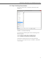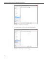
1
INSTRUCTION MANUAL 9522B Iridium Satellite Modem and COM9522B Interface Modem 7/14 C o p y r i g h t © 2 0 0 9 - 2 0 1 4 C a m p b e l l S c i e n t i f i c , I n c . Limited Warranty “Products manufactured by CSI are warranted by CSI to be free from defects in materials and workmanship under normal use and service for twelve months from the date of shipment unless otherwise specified in the corresponding product manual. (Product manuals are available for review online at www.campbellsci.com.) Products not manufactured by CSI, but that are resold by CSI, are warranted only to the limits extended by the original manufacturer. Batteries, fine-wire thermocouples, desiccant, and other consumables have no warranty. CSI’s obligation under this warranty is limited to repairing or replacing (at CSI’s option) defective Products, which shall be the sole and exclusive remedy under this warranty. The Customer assumes all costs of removing, reinstalling, and shipping defective Products to CSI. CSI will return such Products by surface carrier prepaid within the continental United States of America. To all other locations, CSI will return such Products best way CIP (port of entry) per Incoterms ® 2010. This warranty shall not apply to any Products which have been subjected to modification, misuse, neglect, improper service, accidents of nature, or shipping damage. This warranty is in lieu of all other warranties, expressed or implied. The warranty for installation services performed by CSI such as programming to customer specifications, electrical connections to Products manufactured by CSI, and Product specific training, is part of CSI's product warranty. CSI EXPRESSLY DISCLAIMS AND EXCLUDES ANY IMPLIED WARRANTIES OF MERCHANTABILITY OR FITNESS FOR A PARTICULAR PURPOSE. CSI hereby disclaims, to the fullest extent allowed by applicable law, any and all warranties and conditions with respect to the Products, whether express, implied or statutory, other than those expressly provided herein.” Assistance Products may not be returned without prior authorization. The following contact information is for US and international customers residing in countries served by Campbell Scientific, Inc. directly. Affiliate companies handle repairs for customers within their territories. Please visit www.campbellsci.com to determine which Campbell Scientific company serves your country. To obtain a Returned Materials Authorization (RMA), contact CAMPBELL SCIENTIFIC, INC., phone (435) 227-9000. After an application engineer determines the nature of the problem, an RMA number will be issued. Please write this number clearly on the outside of the shipping container. Campbell Scientific’s shipping address is: CAMPBELL SCIENTIFIC, INC. RMA#_____ 815 West 1800 North Logan, Utah 84321-1784 For all returns, the customer must fill out a “Statement of Product Cleanliness and Decontamination” form and comply with the requirements specified in it. The form is available from our web site at www.campbellsci.com/repair. A completed form must be either emailed to [email protected] or faxed to (435) 227-9106. Campbell Scientific is unable to process any returns until we receive this form. If the form is not received within three days of product receipt or is incomplete, the product will be returned to the customer at the customer’s expense. Campbell Scientific reserves the right to refuse service on products that were exposed to contaminants that may cause health or safety concerns for our employees. Precautions DANGER — MANY HAZARDS ARE ASSOCIATED WITH INSTALLING, USING, MAINTAINING, AND WORKING ON OR AROUND TRIPODS, TOWERS, AND ANY ATTACHMENTS TO TRIPODS AND TOWERS SUCH AS SENSORS, CROSSARMS, ENCLOSURES, ANTENNAS, ETC. FAILURE TO PROPERLY AND COMPLETELY ASSEMBLE, INSTALL, OPERATE, USE, AND MAINTAIN TRIPODS, TOWERS, AND ATTACHMENTS, AND FAILURE TO HEED WARNINGS, INCREASES THE RISK OF DEATH, ACCIDENT, SERIOUS INJURY, PROPERTY DAMAGE, AND PRODUCT FAILURE. TAKE ALL REASONABLE PRECAUTIONS TO AVOID THESE HAZARDS. CHECK WITH YOUR ORGANIZATION'S SAFETY COORDINATOR (OR POLICY) FOR PROCEDURES AND REQUIRED PROTECTIVE EQUIPMENT PRIOR TO PERFORMING ANY WORK. Use tripods, towers, and attachments to tripods and towers only for purposes for which they are designed. Do not exceed design limits. Be familiar and comply with all instructions provided in product manuals. Manuals are available at www.campbellsci.com or by telephoning (435) 227-9000 (USA). You are responsible for conformance with governing codes and regulations, including safety regulations, and the integrity and location of structures or land to which towers, tripods, and any attachments are attached. Installation sites should be evaluated and approved by a qualified engineer. If questions or concerns arise regarding installation, use, or maintenance of tripods, towers, attachments, or electrical connections, consult with a licensed and qualified engineer or electrician. General • Prior to performing site or installation work, obtain required approvals and permits. Comply with all governing structure-height regulations, such as those of the FAA in the USA. • Use only qualified personnel for installation, use, and maintenance of tripods and towers, and any attachments to tripods and towers. The use of licensed and qualified contractors is highly recommended. • Read all applicable instructions carefully and understand procedures thoroughly before beginning work. • Wear a hardhat and eye protection, and take other appropriate safety precautions while working on or around tripods and towers. • Do not climb tripods or towers at any time, and prohibit climbing by other persons. Take reasonable precautions to secure tripod and tower sites from trespassers. • Use only manufacturer recommended parts, materials, and tools. Utility and Electrical • You can be killed or sustain serious bodily injury if the tripod, tower, or attachments you are installing, constructing, using, or maintaining, or a tool, stake, or anchor, come in contact with overhead or underground utility lines. • Maintain a distance of at least one-and-one-half times structure height, 20 feet, or the distance required by applicable law, whichever is greater, between overhead utility lines and the structure (tripod, tower, attachments, or tools). • Prior to performing site or installation work, inform all utility companies and have all underground utilities marked. • Comply with all electrical codes. Electrical equipment and related grounding devices should be installed by a licensed and qualified electrician. Elevated Work and Weather • Exercise extreme caution when performing elevated work. • Use appropriate equipment and safety practices. • During installation and maintenance, keep tower and tripod sites clear of un-trained or nonessential personnel. Take precautions to prevent elevated tools and objects from dropping. • Do not perform any work in inclement weather, including wind, rain, snow, lightning, etc. Maintenance • Periodically (at least yearly) check for wear and damage, including corrosion, stress cracks, frayed cables, loose cable clamps, cable tightness, etc. and take necessary corrective actions. • Periodically (at least yearly) check electrical ground connections. WHILE EVERY ATTEMPT IS MADE TO EMBODY THE HIGHEST DEGREE OF SAFETY IN ALL CAMPBELL SCIENTIFIC PRODUCTS, THE CUSTOMER ASSUMES ALL RISK FROM ANY INJURY RESULTING FROM IMPROPER INSTALLATION, USE, OR MAINTENANCE OF TRIPODS, TOWERS, OR ATTACHMENTS TO TRIPODS AND TOWERS SUCH AS SENSORS, CROSSARMS, ENCLOSURES, ANTENNAS, ETC. Table of Contents PDF viewers: These page numbers refer to the printed version of this document. Use the PDF reader bookmarks tab for links to specific sections. 1. Overview ...................................................................... 1 1.1 1.2 1.3 1.4 1.5 General Description and Modes of Operation ...................................... 1 Modem Models and Accessories ......................................................... 1 Hardware Overview ............................................................................. 2 Power Control ...................................................................................... 3 Where it Works .................................................................................... 4 2. Specifications ............................................................. 5 2.1 2.2 9522B Specifications ........................................................................... 5 COM9522B Specifications .................................................................. 5 3. Iridium SIM Card and Modem Setup ......................... 5 3.1 3.2 Iridium SIM Card Use.......................................................................... 5 Setup of Iridium Modems .................................................................... 6 3.2.1 Step 1: Hardware Connections ...................................................... 6 3.2.2 Step 2: DevConfig Connection...................................................... 6 3.2.3 Step 3: DevConfig Communications ............................................. 7 4. Datalogger Configuration......................................... 10 5. LoggerNet Configuration ......................................... 11 5.1 Setup of LoggerNet Communications ................................................ 11 5.1.1 Step 1: LoggerNet Setup ............................................................. 12 5.1.2 Step 2: ComPort Configuration................................................... 13 5.1.3 Step 3: Generic Modem Configuration ....................................... 14 5.1.4 Step 4: Generic Modem Configuration Continued ..................... 15 5.1.5 Step 5: PakBusPort Configuration .............................................. 16 5.1.6 Step 6: CR1000 Configuration.................................................... 17 6. Remote Modem Configuration................................. 18 6.1 6.2 Program Example 1............................................................................ 19 Program Example 2............................................................................ 20 7. Troubleshooting Tools and Tips ............................. 21 Appendices A. Sample Data Transfer Calculations....................... A-1 B. Hardware Installation ............................................. B-1 B.1 SIM Card Installation ....................................................................... B-1 i Table of Contents B.2 B.3 Antenna Installation ........................................................................ B-2 9522B Modem Installation .............................................................. B-4 C. Unlocking a SIM Card ............................................. C-1 C.1 C.2 Handset Method .............................................................................. C-1 DevConfig Method .......................................................................... C-1 D. Interfacing LoggerNet to RUDICS .......................... D-1 D.1 D.2 D.3 D.4 Base Station System Requirements ................................................. D-1 Remote Station Requirements ......................................................... D-1 Serial Port Redirector ...................................................................... D-1 LoggerNet Setup.............................................................................. D-3 D.4.1 Step 1: ComPort Configuration ................................................ D-3 D.4.2 Step 2: Generic Modem Configuration .................................... D-4 Figures 1-1. 1-2. 1-3. 3-1. 3-2. 3-3. 3-4. 3-5. 3-6. 4-1. 4-2. 5-1. 5-2. 5-3. 5-4. 5-5. 5-6. 5-7. B-1. B-2. B-3. B-4. B-5. D-1. D-2. D-3. D-4. D-5. D-6. 9522B Base Station Configuration ...................................................... 4 9522B Remote Station RS-232 Configuration .................................... 4 9522B Remote Station CS I/O Configuration ..................................... 4 Starting a DevConfig Session .............................................................. 6 Connected in DevConfig ..................................................................... 7 CR1000 AT Command String ............................................................. 8 Modem Reply to Command String...................................................... 8 AT&V Command ................................................................................ 9 Modem Setting Confirmation .............................................................. 9 Device Configuration Utility ............................................................. 10 ComPorts Settings Tab ...................................................................... 11 LoggerNet Setup Tree ....................................................................... 12 ComPort Configuration ..................................................................... 13 Generic – Hardware Configuration ................................................... 14 Generic – Modem Configuration....................................................... 15 PakBus Port Configuration ................................................................ 16 CR1000 Hardware Configuration...................................................... 17 CR1000 Schedule Configuration....................................................... 18 SIM Card Housing .......................................................................... B-1 SIM Card Slot.................................................................................. B-1 Installed SIM Card .......................................................................... B-2 Antenna, Mount, and Cable ............................................................. B-3 Antenna Attached to Mount ............................................................ B-3 Serial Port Redirector Setup ............................................................ D-2 Serial Port Redirector Setup (cont’d) .............................................. D-2 Serial Port Redirector Setup (cont’d) .............................................. D-3 ComPort Configuration ................................................................... D-3 Generic Modem Configuration........................................................ D-4 Generic Modem Configuration (cont’d) .......................................... D-5 1-1. 1-2. 1-3. A-1. Equipment List for Base and Remote Stations .................................... 2 Remote Station COM9522B Wiring ................................................... 3 Base Station COM9522B Wiring ........................................................ 3 Data Transfer Time Estimates ......................................................... A-1 Tables ii 9522B Iridium Satellite Modem and COM9522B Interface Modem 1. Overview 1.1 General Description and Modes of Operation The Iridium satellite network consists of a constellation of 66 satellites situated in six planes in low-earth orbit. Each plane is populated by 11 satellites in polar orbits, giving the Iridium network excellent coverage in high latitudes that equatorial satellites often cannot reach. Iridium provides five different services: dial-up data, Short Burst Data (SBD), Short Messaging Service (SMS), Internet Connection, and Router Based Unrestricted Digital Internetworking Connectivity Solution (RUDICS). For the purposes of this manual, we will discuss dial-up data and RUDICS as the preferred methods of connecting with Campbell Scientific dataloggers. However, while other services may not be directly relevant to datalogger operations, the end user may find them valuable. Please contact your Iridium service provider with questions on these methods. 1.2 Modem Models and Accessories The Iridium satellite system used by Campbell Scientific consists of the 9522B modem, COM9522B interface module kit, data cables, antenna and power supply. The base and remote stations use the same modem type, which both require a change to their configuration. When possible, the recommended connection of the remote modem to a datalogger is via the RS-232 port. It is possible to communicate with a datalogger via either the CS I/O port or COM Ports 1–4. All datalogger connections require appropriate cabling and interface accessories (see TABLE 1-1). The COM9522B is required to connect the modem to the datalogger or computer and an appropriate power source. For remote applications where AC power is not available, it is recommended to operate the modem on a schedule to avoid discharging the battery power supply. The antenna used for both Iridium modems is the Iridium fixed mast antenna, pn 30741 (also known as AT1621-142). For best signal reception, the antenna should be mounted so that it has an unobstructed view of the sky and the horizon. Reception quality changes as satellites move overhead; therefore, it is critical that the view be clear. See Section 7, Troubleshooting Tools and Tips, for information about checking signal quality. 1 9522B Iridium Satellite Modem and COM9522B Interface Modem TABLE 1-1. Equipment List for Base and Remote Stations Base Station 30693 9522B L-Band Data Modem Remote Station 30693 9522B L-Band Data Modem 30627 Mounting Kit 30741 Antenna 30741 Antenna 18017-L Antenna Cable 18017-L Antenna Cable 18436 Right Angle SMA Adaptor (may be required depending on installation) 18436 Right Angle SMA Adaptor 30653 COM9522B 30653 COM9522B Iridium SIM Card (comes with modem) Iridium SIM Card (comes with modem) 10873 serial cable (used to connect PC to the COM9522B) 18663 Null Modem Cable (1 ft lead) OR SC932A with 10873 and SC12 (only required if using CSI/O port of datalogger) OR SC110 9-pin Male DTE to Bare Leads (only required if using a datalogger COM Port) 30626 Mounting Kit for 30741 Antenna 30626 Mounting Kit for 30741 Antenna The Iridium Satellite Modem and Interface Kit (pn 30694) includes most items shown above for a base or remote station. It does not include the 18017-L Antenna Cable which must be ordered at the desired length. Also, it includes only the default option (18663 Null Modem Cable) for connecting the remote station to a datalogger. 1.3 Hardware Overview TABLE 1-1 lists the hardware typically used for both a base and remote station. TABLE 1-2 and TABLE 1-3 list common wiring for both the remote and base stations. FIGURE 1-1 to FIGURE 1-3 represent the typical configurations of the base and remote stations. Please refer to Appendix B, Hardware Installation, for a thorough description of the installation procedure for both the base and remote stations. WARNING 2 Be sure that the 30741 antenna is connected to either of the modems before applying power, as damage to the equipment may occur. 9522B Iridium Satellite Modem and COM9522B Interface Modem TABLE 1-2. Remote Station COM9522B Wiring Hardware ComPort 9522B COM9522B 18663 RS-232 SC932A (optional) CS I/O Description Color Connection Antenna “ANT” SMA connector to antenna cable using 18436 adaptor COM9522B Interface 26-pin ribbon cable connector Power Control Yellow Control Port Datalogger (5V power trigger) Ground Black G (Datalogger / Direct to Station Power Supply) Modem Power Red 12V (Datalogger / Direct to Station Power Supply) Serial Communications 18663 9-pin connector of COM9522B “DCE Device” 10873 9-pin connector of COM9522B “Datalogger” SC12 CS I/O port of Datalogger TABLE 1-3. Base Station COM9522B Wiring Hardware ComPort Description Color Antenna “ANT” SMA connector to antenna cable COM9522B Interface 26-pin ribbon cable connector 9522B COM9522B 10873 RS-232 1.4 Connection Power Control Yellow 12V (Direct to Station Power Supply) Ground Black G (Direct to Station Power Supply) Modem Power Red 12V (Direct to Station Power Supply) Serial Communications 10873 Connect to PC Power Control The COM9522B will be used to control power to the modem with the use of 5 Vdc trigger on a datalogger control port (ex. C1: yellow wire). It is possible to power the modem from the datalogger; however, it is recommended that a separate power source be used for the modem to avoid catastrophic loss of data in case of power failure. The COM9522B must draw power directly from a 12 Vdc power supply (power +: Red, ground/power –: Black). 3 9522B Iridium Satellite Modem and COM9522B Interface Modem FIGURE 1-1. 9522B Base Station Configuration FIGURE 1-2. 9522B Remote Station RS-232 Configuration FIGURE 1-3. 9522B Remote Station CS I/O Configuration 1.5 Where it Works Unlike other satellite systems, the Iridium satellite network is located in a low polar orbit, giving the system complete global coverage. Their relatively low altitude (780 km) means that they are situated close to transmitting modems and, therefore, require less transmission energy. Additionally, the Iridium network consists of 66 satellites in 11 planes with an 4 9522B Iridium Satellite Modem and COM9522B Interface Modem extra six satellites reserved as backups. This redundancy potentially gives the iridium system excellent reliability versus other systems that rely on two or three satellites. 2. Specifications 2.1 2.2 9522B Specifications Power Supply Operating: Standby: 4 to 32 Vdc, 333 mA @ 12 Vdc 125 mA @ 12 Vdc Environmental Operating temperature: Operating humidity: Storage temperature: Storage humidity: –30 to +70 °C 25% to 75% –40 to +85 °C 93% (max) RF Interface Frequency range: Duplexing method: Oscillator stability: Input/output impedance: Multiplexing method: 1616 MHz to 1626.5 MHz TDD (Time Domain Duplex) ± 1.5 ppm 50 ohms TDMA/FDMA Mechanical Length: Width: Depth: Weight: 162 mm (6.38 in) 81 mm (3.19 in) 28 mm (1.1 in) 420 g (14.82 oz) (approximate) COM9522B Specifications Power Supply Operating: 3. 9 to 18 Vdc, 12 Vdc nominal, 32 mA (On State Max), 20 µA (Off State) Max Supply Current: 2500 mA Operating Temperature: –40 to +70 °C Control Input Voltage Guaranteed Off: Guaranteed On: Maximum Voltage: < 1.25 volts > 3.24 volts 18 Vdc Iridium SIM Card and Modem Setup 3.1 Iridium SIM Card Use Please note that the new SIM cards that come with the Iridium modems are already unlocked. The SIM cards can be activated through Joubeh Technologies at: 5 9522B Iridium Satellite Modem and COM9522B Interface Modem 11 Thornhill Dr., Suite 201 Dartmouth, NS, CANADA, B3B 1R9 T: (902) 405-4428 www.joubeh.com If you have acquired a SIM card that needs to be unlocked, please see Appendix C. This should be done before going to the field. 3.2 Setup of Iridium Modems Once the SIM cards are unlocked (Appendix C), it is necessary to set up the base and remote modems using Device Configuration Utility (DevConfig). (The base and remote modems can also be set up using a terminal emulation program such as Procomm or HyperTerminal.) 3.2.1 Step 1: Hardware Connections Connect the Iridium satellite modem to the COM9522B and connect a serial cable from the COM9522B to a COM Port on your computer. Connect the COM9522B to the power supply. Be sure to connect the yellow power control wire to +12V, so that the COM9522B will switch on power for the 9522B. 3.2.2 Step 2: DevConfig Connection Open DevConfig. Under Device Type, select Unknown. Select the appropriate Communication Port and set the Baud Rate to 19200. Press Connect. FIGURE 3-1. Starting a DevConfig Session 6 9522B Iridium Satellite Modem and COM9522B Interface Modem 3.2.3 Step 3: DevConfig Communications Once you have clicked Connect, you should be connected to the modem (FIGURE 3-2). FIGURE 3-2. Connected in DevConfig Type the following command string that correlates to the datalogger and/or Baud rate being used: CR1000: AT&F0 S0=1 &D0 +IPR=6,0 V0 &K0 &W0 &Y0 CR10X: AT&F0 S0=1 &D0 +IPR=5,0 V0 &K0 &W0 &Y0 The appropriate command string will need to be used in both modems. Press “Enter” once the string has been input. See FIGURE 3-3 and FIGURE 3-4 for an example. 7 9522B Iridium Satellite Modem and COM9522B Interface Modem FIGURE 3-3. CR1000 AT Command String The modem should add a 0 at the end of the command string (FIGURE 3-4). FIGURE 3-4. Modem Reply to Command String 8 9522B Iridium Satellite Modem and COM9522B Interface Modem To ensure that the settings have been stored in the modem type the command: AT&V. FIGURE 3-5. AT&V Command The modem will return the following as seen in FIGURE 3-6 and should include the elements just added. FIGURE 3-6. Modem Setting Confirmation 9 9522B Iridium Satellite Modem and COM9522B Interface Modem This is a summary of the currently active modem profile and ensures that when power is cycled to the modem it will have the correct auto-answer, DTR, and flow control settings. Exit Hyperterminal and save your settings for later. 4. Datalogger Configuration To ensure proper communications with the datalogger, it will be necessary to configure the datalogger. This can be done via DevConfig. Follow the instructions provided to make a connection to the datalogger. FIGURE 4-1. Device Configuration Utility Once connected, select the ComPorts Settings tab (FIGURE 4-2). With the ComPort set to RS-232, set the Verify Interval to its maximum value of 65534 seconds and select the 19.2K Fixed Baud Rate. If you require the use of the CS I/O port for communications, select the CSI/O – ME ComPort and set the Baud Rate to 19.2K Fixed. If you require the use of a COM port for communications, select the appropriate COMPort and set the Baud Rate to 19.2K Fixed. Make any additional changes required for your application. Press the Apply button to save the changes. 10 9522B Iridium Satellite Modem and COM9522B Interface Modem FIGURE 4-2. ComPorts Settings Tab 5. LoggerNet Configuration 5.1 Setup of LoggerNet Communications This section deals with the proper software setup of a remote section that uses the COM9522B in Campbell Scientific’s LoggerNet datalogger support software. All screenshots are based on the CR1000 datalogger. Please note that array-based dataloggers (for example, CR10X) can be configured in LoggerNet in a similar fashion. 11 9522B Iridium Satellite Modem and COM9522B Interface Modem 5.1.1 Step 1: LoggerNet Setup Start LoggerNet and open the Setup screen from the Main category of the toolbar. Start the configuration by clicking on the Add Root button. From the Add submenu make the following selections: ComPort Communications Generic PakBusPort CR1000 Finally, click the Close button on the Add submenu. Your setup tree should appear as in FIGURE 5-1. FIGURE 5-1. LoggerNet Setup Tree 12 9522B Iridium Satellite Modem and COM9522B Interface Modem 5.1.2 Step 2: ComPort Configuration With the setup tree entered, you will now need to complete the configuration of each element. Start with selecting the ComPort element at the root of the tree (FIGURE 5-2). Be sure that the ComPort Connection is correct for the computer used as part of your base station, and make sure that the Communications Enabled box is checked. Set the Extra Response Time and ComPort Communication Delay to 3 seconds. Set the Delay Hangup to 200 ms. This will prevent LoggerNet from hanging up whenever there is a slight lag in transmission time, which is common in satellite applications. FIGURE 5-2. ComPort Configuration 13 9522B Iridium Satellite Modem and COM9522B Interface Modem 5.1.3 Step 3: Generic Modem Configuration Select the Generic element as in FIGURE 5-3. Ensure that the Communications Enabled box is checked, change the Maximum Baud Rate to 19200 (9600 for a CR10X), set the Extra Response Time to 3 seconds, change the Maximum Packet Size to 1000, and set the Delay Hangup to 200 ms. It is recommended that you set a Maximum Time On-Line as part of your configuration. Once complete, move to Step 4 to finish the configuration of the Generic element. FIGURE 5-3. Generic – Hardware Configuration 14 9522B Iridium Satellite Modem and COM9522B Interface Modem 5.1.4 Step 4: Generic Modem Configuration Continued Click on the Modem tab located next to the Hardware tab (FIGURE 5-4). Set the RTS CTS Use to “3. The RTS line will be lowered”. In the Dial Script box enter the following string: T"^m" "ATV1&D0&K0^m" R"OK"1200 "ATDT00XXXXXXXXXXXX^m" R"CONNECT"50000 and in the End Script enter: T"+++" R"OK"1200 "ATH^m" R"OK"2000 NOTE The Xs in the Dial Script represent the number of the remote modem being used. You must enter the 12-digit number supplied by your service provider. FIGURE 5-4. Generic – Modem Configuration 15 9522B Iridium Satellite Modem and COM9522B Interface Modem 5.1.5 Step 5: PakBusPort Configuration As shown in FIGURE 5-5, select the PakBusPort. Be sure the Communications Enabled box is checked, change the Maximum Baud Rate to 19200 (9600 for a CR10X), set the Beacon Interval to 0, set the Extra Response Time to 15 seconds, and, if present, set the Delay Hangup to 200 ms. You may change other settings in this configuration to suit your particular application. Once complete, move to Step 6 to configure the datalogger. FIGURE 5-5. PakBus Port Configuration 16 9522B Iridium Satellite Modem and COM9522B Interface Modem 5.1.6 Step 6: CR1000 Configuration Select your datalogger as shown in FIGURE 5-6. Be sure that the Communications Enabled box is checked and that the PakBus Address is correct for the datalogger being used. Set the Delay Hangup to 200 ms. FIGURE 5-6. CR1000 Hardware Configuration Select the Schedule tab and configure the Collection Interval as required for your application. Be sure that the Scheduled Collection Enabled box is checked. FIGURE 5-7 shows an example of a daily scheduled data collection that is to start at 1:00pm. The number of retries and the retry interval are left in their default state in the example. These values should be adjusted as required. Once all configurations are complete, click the Apply button in the lower left hand corner. The station is now set up in LoggerNet. 17 9522B Iridium Satellite Modem and COM9522B Interface Modem FIGURE 5-7. CR1000 Schedule Configuration 6. Remote Modem Configuration As a matter of system redundancy, it is recommended that the following programming be used as part of your datalogger program. If this programming is not used, it is possible that the remote modem may lose its configuration. If this occurs, remote communication will no longer be available. The program examples are for a CR1000, but they are adaptable to the CR800 series and CR3000 dataloggers. 18 9522B Iridium Satellite Modem and COM9522B Interface Modem 6.1 Program Example 1 In example 1, the station is a solar powered site where power management is a concern. Modem power is controlled by the COM9522B via control port 1. During this time, the modem is sent its configuration via the RS-232 port and the remainder of the time is used for actual communications. The modem is powered up twice per day for 15 minutes each time. 'CR1000 Series Datalogger 'Declare Public Variables 'Variables for Iridium Configuration Public SetupStr As String * 51 Public configure_modem As Boolean 'Main Program BeginProg 'Ensure the control port used to trigger power to the modem is set as an output. 'In this example control port 1 is used to turn power on/off for the modem. PortSet (1,1) PortSet (1,0) Scan (5,Sec,3,0) 'Activate Iridium Modems at Noon & Midnight Daily for 15 minutes each time. 'Allow modem warmup time & check settings (5 minutes) & data transmissions (10 minutes) ' *** Use intervals that are applicable for your application *** If TimeIntoInterval (715,720,Min) Then PortSet (1,1) If TimeIntoInterval (10,720,Min) Then PortSet (1,0) 'Allow the modem 1 minute for warm up before sending settings. Once settings are 'sent to the modem allow another 4 minutes to ensure the modem is registered on 'the network before attempting communications. If IfTime (716,720,min) Then configure_modem = true If configure_modem = true Then SerialOpen (ComRS232,19200,0,0,2000) Delay (0,1,Sec) 'Send the correct settings SetupStr = "AT&F0 S0=1 &D0 +IPR=6,0 V0 &K0 &W0 &Y0" & CHR(13) & CHR(10) SerialOut (ComRS232,SetupStr,"",0,0) configure_modem = false SerialClose (ComRS232) EndIf NextScan EndProg 19 9522B Iridium Satellite Modem and COM9522B Interface Modem 6.2 Program Example 2 In example 2, the station is a solar powered site where power management is a concern. Modem power is controlled by the COM9522B via control port 1. During this time, the modem is sent its configuration via the CS I/O port and the remainder of the time is used for actual communications. For details on programming for the CR10X, contact Campbell Scientific. Please note that the interface between the CR10X and the COM9522B requires the use of SC932A CS I/O to RS-232 DCE interface. 'CR1000 Series Datalogger 'Declare Public Variables 'Variables for Iridium Configuration Public SetupStr As String * 51 Public configure_modem As Boolean 'Main Program BeginProg 'Ensure the control port used to trigger power to the modem is set as an output. 'In this example control port 1 is used to turn power on/off for the modem. PortSet (1,1) PortSet (1,0) Scan (5,Sec,3,0) 'Activate Iridium Modems at Noon & Midnight Daily for 15 minutes each time. 'Allow modem warmup time & check settings (5 minutes) & data transmissions (10 minutes) ' *** Use intervals that are applicable for your application *** If TimeIntoInterval (715,720,Min) Then PortSet (1,1) If TimeIntoInterval (10,720,Min) Then PortSet (1,0) 'Allow the modem 1 minute for warm up before sending settings. Once settings are 'sent to the modem allow another 4 minutes to ensure the modem is registered on 'the network before attempting communications. If IfTime (716,720,min) Then configure_modem = true If configure_modem = true Then SerialOpen (ComME,19200,0,0,2000) Delay (0,1,Sec) 'Send the correct settings SetupStr = "AT&F0 S0=1 &D0 +IPR=6,0 V0 &K0 &W0 &Y0" & CHR(13) & CHR(10) SerialOut (ComME,SetupStr,"",0,0) configure_modem = false SerialClose (ComME) EndIf NextScan EndProg 20 9522B Iridium Satellite Modem and COM9522B Interface Modem 7. Troubleshooting Tools and Tips Problem: I have intermittent successful connections between the remote and base station modem. The signal strength is weak and the data transfer speeds are slow. Solution: The antenna may not have a complete 180° view of the sky. Some objects and debris such as snow and trees can interfere with communications. Make sure there are no obstructions to the antennas when installing. You may need to reposition or elevate your antenna to obtain the best reception. The Signal Quality AT command can be used to confirm signal strength during installation/repositioning of the antenna. This will require use of a laptop connected to the COM9522B interface and a terminal emulator. Once the terminal emulator is connected, the following command can be entered to check signal strength: AT+CSQ The modem should return a value of between 0 and 5 within 10 seconds. Attempt to get the largest value during your installation/repositioning. Problem: LoggerNet immediately brings back an error message saying that communications with the station have failed. Solution: Sometimes PakBus© beacons sent to other stations by LoggerNet interfere with successful communications using Iridium Satellite Modems. Either turn PakBus© beaconing off or disable communications with your other stations when you attempt to download using Iridium. This can be accomplished in the Setup screen in LoggerNet. Finally, restart LoggerNet to clear the communications queue of any tasks. Problem: LoggerNet makes several attempts to connect to the remote station with no success. The failure is not immediate and the LoggerNet LogTool may show a “No Carrier Detected” error. Solution: It is possible that the base modem has lost its configuration. Resend the configuration as shown in Section 3.2, Setup of Iridium Modems, and attempt communications again. Problem: I am using Iridium to communicate through the CS I/O port on my datalogger. Whenever I try connecting with the datalogger, LoggerNet reports that communication with the station has failed. This message takes several seconds to appear. Solution: You may have connected your SC932A device backwards at the remote station. When you install the SC932A, it is imperative to make sure that the device is connected in the proper way. Follow the label on the device for the proper connections. 21 9522B Iridium Satellite Modem and COM9522B Interface Modem 22 Appendix A. Sample Data Transfer Calculations NOTE The calculations below are based upon maximum theoretical throughputs. Real world transmission times for the Iridium Satellite Network have proven to be as much as twice as slow. When transmitting the data back from the station, the power consumption of the modem must be taken into account in order to avoid excessive discharge of the battery power supply. To get an idea of what the transmission time and associated power drain might be for a typical meteorological station, consider the following example: A station measures wind speed and direction, precipitation, temperature and relative humidity, solar radiation, and barometric pressure. The datalogger is a CR1000. The monthly data file contains 2 data tables; a small maintenance table and a 30 parameter meteorological data table. The size of a monthly ASCII data file is 124 kB. If the station’s data were downloaded monthly, the time (T) for the data transfer could be calculated as shown below: T(Download) = File size (kB) / Transfer Rate (10 kB/min) With a file size of 124 kB and a transfer rate of 10 kB per minute, the download time is approximately 13 minutes. If the data were downloaded daily, the file would be much smaller, approximately 5 kB. A daily data transfer time would be approximately 30 seconds. Please note that a 15 second connection time should be added to the above times to account for the initial connection time. TABLE A-1 below shows the transfer time depending on whether data is collected daily, weekly, or monthly. TABLE A-1. Data Transfer Time Estimates Collection Interval File size (kB) Transfer time Monthly 124 13 minutes Weekly 35 3.5 minutes Daily 5 30 seconds The CR10X datalogger generates data arrays which are very similar in size to the table-based dataloggers. For example, the station mentioned above generates a 124 kB meteorological data table and a 2 kB maintenance table each month. If a CR10X is employed to measure the same parameters, the data arrays would be the same size. A-1 Appendix A. Sample Data Transfer Calculations Power Calculation NOTE When configuring a power supply (that is, solar panel and battery) for a remote station, it is essential to design with the worst case scenario in mind. This will help to ensure that the station will perform as expected. The power calculation for data transfer can be carried out now that the transfer time is known. The modem has the following power consumption characteristics: - 0 mA when powered off - 300 mA stand-by - 800 mA transmit (2500 mA max) The time slot for powering the modem must be long enough to allow for the complete downloading of the datalogger’s data and connection times. Refer to TABLE A-1 or make your own calculation based on the collection interval you intend to use. It is advisable to make the time slot longer than the minimum download time required to allow for initial connection times and possible retries. It is also advisable to arrange the time slot during a time of day when the power supply is most robust. For a solar powered station, this would be the early afternoon. The periods of power consumption in a day can be divided up as follows: Period A: the modem is powered off – 0 mA Period B: the modem powered up in stand-by mode – 300 mA Period C: the modem is transmitting the data – 2500 mA Now consider a 35 kB data file size and a datalogger programmed power time slot of 1/2 hour; the periods above become: Period A = 24 hours - Period B – Period C Period B = 30 minutes – Period C Period C = 3.5 minutes (from TABLE A-1) We can substitute in the Period B and C values to obtain all Periods: Period A = 23.5 hours = 0.0 (A hr)/Day Period B = 26.5 minutes @ 300 mA = 0.1325 (A hr)/Day Period C = 3.5 minutes @ 2500 mA = 0.1458 (A hr)/Day The total draw for the data transfer is the sum of the periods, 0.2783 (A hr)/Day, one day per week. NOTE The (A hr)/Day calculation for each period is as follows: = Current Draw in mA • (Interval in minutes / 60 min) / 1000 A-2 Appendix B. Hardware Installation The hardware shown in this appendix consists only of hardware listed in TABLE 1-1. Although it may be possible to use other hardware, it will not be addressed in this appendix. WARNING Do not connect power to either modem until installation is complete, as damage to the equipment may occur. B.1 SIM Card Installation These installation steps apply to both the base and remote modems. Be sure the correct card is installed in the proper modem. Start by removing the cover on the top of the modem (FIGURE B-1). This will require the use of a 5/64 Allen wrench. Open the card slot by pushing the card holder away from the end labeled “Lock”, until it is able to flip up. Place the card in the slot in the proper orientation as shown in FIGURE B-1. The card notch will need to line up with the notch of the card slot. Close and lock the card slot into place (FIGURE B-2 and FIGURE B-3). Once complete, replace the housing cover. SIM Card Housing FIGURE B-1. SIM Card Housing FIGURE B-2. SIM Card Slot B-1 Appendix B. Hardware Installation Installed SIM Card Card Notch FIGURE B-3. Installed SIM Card B.2 Antenna Installation These instructions apply to both the base and remote stations. This installation does not have to precede the modem installation. It should be conducted in the most convenient and logical order. The installation of the 30741 antenna and cable should begin by feeding the antenna cable through the nut, then spacer, and finally antenna mount (FIGURE B-4). Next, loosen the four Phillips screws at the base of the antenna and separate the two pieces. Feed the antenna cable through the bottom half and secure the cable to the connector on the top half (FIGURE B-4). Once the cable is in place, reattach the bottom half of the antenna and secure the four Phillips screws. Be sure to use the alignment notches on the two halves before securing the antenna together. B-2 Appendix B. Hardware Installation FIGURE B-4. Antenna, Mount, and Cable Thread the antenna onto the 3/4 inch supplied nut, being sure not to cross the threads (FIGURE B-5). FIGURE B-5. Antenna Attached to Mount B-3 Appendix B. Hardware Installation B.3 9522B Modem Installation The base station installation should be conducted before proceeding to the field to conduct the remote station installation. With the base station installed first, it will provide the opportunity to test the communications from the base station before going to and/or while still in the field. If there is a malfunction, you may be able to address the problem without having to return to the remote station. The modem installation should employ the following steps: 1. Secure the 30627 mount to the 9522B interface. Secure this assembly in the enclosure in an appropriate location. Be sure to keep in mind all cable runs (that is, antenna, power/control, and interface). 2. Connect the ribbon cable of the 9522B interface to the modem. Connect the other end of the ribbon cable to the COM9522B. 3. Connect the 10873 serial cable (base station) to the data port of the interface to the PC serial port. 4. For the remote station, connect the 18663 serial cable between the COM9522B data port and the datalogger, unless using datalogger’s CS I/O port (refer to FIGURE 1-3). 5. Connect the antenna cable to the “ANT” connector of the modem. Use the 18436 right angle adaptor between the antenna cable and modem to reduce cable strain. 6. Connect the bare leads of the COM9522B to datalogger and power supply. Start your connections with the power control leads. Be sure power is off at the power supply when making these connections. Once all the items are attached, power can be applied to the modem. B-4 Appendix C. Unlocking a SIM Card There are two methods to unlock a SIM card. The equipment you have available will dictate which method is used. C.1 Handset Method To unlock the Iridium SIM card permanently using the Iridium Handset, follow these instructions. Install the SIM card. Attach the antenna and 9522B interface. Attach the handset as required. Apply power to the modem. The handset will request the PIN number before proceeding. Once you enter the PIN number (default 1111), the modem will register itself. You will need to navigate the menus of the handset as follows: • • • • Find “PHONE SETUP”, click ok From this menu select “REQUIRE SIM PIN” Navigate until “OFF” is displayed, select by clicking ok Exit out of the menus once the PIN requirement is deactivated. With the card unlocked, you can continue with your modem setup. C.2 DevConfig Method In order to unlock the SIM cards with this method, you will need DevConfig or a terminal emulator. The configuration will need to be the same as listed in Section 3.2, Setup of Iridium Modems. Refer to Section 3.2 for this setup. NOTE Both SIM cards must be unlocked. When conducting these steps, you will need to have the SIM card installed in the modem. The antenna must be connected and have a sky view for communication with the satellite network. Finally, the unit must be powered. Refer to the appropriate sections of this manual for information about these requirements. Once the modem and DevConfig are ready, enter the following command: AT+CPIN? <Enter> This command requests that the modem respond as to whether a password is required. The expected modem response is: +CPIN: SIM PIN The response confirms that the SIM Card PIN1 code is required to unlock the card. If you get a different response, contact the SIM card provider to determine if a different code is required. If you get a response of “+CPIN: SIM PIN2”, this may mean that the card is already unlocked or requires a different code. C-1 Appendix C. Unlocking a SIM Card The next step is to enter the PIN code for the SIM card. AT+CPIN=”1111” <Enter> The modem should respond with an “OK” which means the PIN code has been accepted. This explanation assumes that the default code of “1111” is being used. If you get an “ERROR” reply, be sure that the command was entered as shown. If you continue to get an error response, contact the SIM card provider to determine if a different code is required. The next step is to enter the command to deactivate the PIN code requirement. If your PIN code is different from the “1111”, use this in the command in its place. AT+CLCK=”SC”,0,”1111” <Enter> The modem should respond with an “OK”, which means the command has been accepted. If you get an “ERROR” reply, be sure that the command was entered as shown. If you continue to get an error response, contact the SIM card provider for further information. The final step should be to test that the SIM card is unlocked and will remain unlocked. Start by powering down the modem and then reapplying power. Allow the modem to warm up for about 30 seconds. The test consists of attempting to dial the 12-digit data number for the other SIM card in DevConfig. ATDT00<12-DIGIT DATA #> <Enter> If you are able to dial the number without getting a prompt for a PIN code, then the code requirement is deactivated. The modem should respond with “NO ANSWER” after several seconds. This assumes the other modem is not communicating. C-2 Appendix D. Interfacing LoggerNet to RUDICS Contact Campbell Scientific if you are interested in using RUDICS. D.1 Base Station System Requirements 1. LoggerNet software version 4.0 or greater 2. Telnet-compliant serial port redirector software 3. Iridium service account, supplied by Iridium service provider. You will also need to make arrangements with service provider to access the RUDICS network. 4. A PC with static IP internet access 5. LoggerNet and serial port redirector software should be referenced for relevant PC hardware requirements D.2 Remote Station Requirements 1. Datalogger configured as described in Section 4, Datalogger Configuration, Section 5.1.5, Step 5: PakBusPort Configuration, and Section 5.1.6, Step 6: CR1000 Configuration 2. Datalogger program should include modem configuration (Section 6, Remote Modem Configuration) 3. Modem configured as described in Section 3.2, Setup of Iridium Modems D.3 Serial Port Redirector To communicate with a remote datalogger using RUDICS, the computer running LoggerNet must have Telnet-compliant serial port redirector software installed (also known as a serial port to telnet emulator software). Currently compatible software can be found here. The software version tested at Campbell Scientific and known to operate is version 2.6.1. www.fabulatech.com/serial-port-redirector.html NOTE Campbell Scientific cannot guarantee that other versions of this software will operate as intended in this application. Any support will need to be requested directly of any third party software provider. Once the software is installed, click on the Add Client Virtual Port button to create a connection to the RUDICS system. Fill in the information in the Add D-1 Appendix D. Interfacing LoggerNet to RUDICS Serial Port window, select an unused serial port, and add the IP address and port number to connect to. FIGURE D-1. Serial Port Redirector Setup Next, click on the Advanced button, and on the Protocol tab, select Telnet. Click OK to create the new virtual serial port connection. Finally, click the power button to enable the connection. FIGURE D-2. Serial Port Redirector Setup (cont’d) D-2 Appendix D. Interfacing LoggerNet to RUDICS FIGURE D-3. Serial Port Redirector Setup (cont’d) D.4 LoggerNet Setup Now that the serial port emulator has been configured, be sure to restart LoggerNet if running. Use the following steps to configure LoggerNet to dial the remote modem. D.4.1 Step 1: ComPort Configuration Configure the connection to use the newly created virtual com port and set the Extra Response Time to 5 seconds. FIGURE D-4. ComPort Configuration D-3 Appendix D. Interfacing LoggerNet to RUDICS D.4.2 Step 2: Generic Modem Configuration Add a new Generic modem to the ComPort, select a Maximum Baud Rate of 115200 and Maximum Packet Size of 1024. FIGURE D-5. Generic Modem Configuration In the Modem tab, add a Dial Script to instruct the RUDICS system to create a new connection to the remote modem. Use the following script to dial the number of the modem to be contacted. Be sure to replace the “X…” below with the 12 digit number supplied by your Service Provider. D2000 T "ATS29=8^M" R "OK" 40000 T "ATS57=9600^M" R "OK" 40000 T "ATDI00XXXXXXXXXXXX^M" R "CONNECT" 40000 Next, add an End Script to close the connection to the remote modem. D1200 T "+++" D1200 T "ATH^M" D-4 Appendix D. Interfacing LoggerNet to RUDICS FIGURE D-6. Generic Modem Configuration (cont’d) Finally, add a PakBusPort and a datalogger and configure them according to the intended application (see Section 5.1.5, Step 5: PakBusPort Configuration, and Section 5.1.6, Step 6: CR1000 Configuration, for LoggerNet configuration details). Be sure to uncheck the PakBus Port Always Open box on the PakBusPort. D-5 Appendix D. Interfacing LoggerNet to RUDICS D-6 Campbell Scientific Companies Campbell Scientific, Inc. (CSI) 815 West 1800 North Logan, Utah 84321 UNITED STATES www.campbellsci.com • [email protected] Campbell Scientific Centro Caribe S.A. (CSCC) 300 N Cementerio, Edificio Breller Santo Domingo, Heredia 40305 COSTA RICA www.campbellsci.cc • [email protected] Campbell Scientific Africa Pty. Ltd. (CSAf) PO Box 2450 Somerset West 7129 SOUTH AFRICA www.csafrica.co.za • [email protected] Campbell Scientific Ltd. (CSL) Campbell Park 80 Hathern Road Shepshed, Loughborough LE12 9GX UNITED KINGDOM www.campbellsci.co.uk • [email protected] Campbell Scientific Australia Pty. Ltd. (CSA) PO Box 8108 Garbutt Post Shop QLD 4814 AUSTRALIA www.campbellsci.com.au • [email protected] Campbell Scientific Ltd. (CSL France) 3 Avenue de la Division Leclerc 92160 ANTONY FRANCE www.campbellsci.fr • [email protected] Campbell Scientific (Beijing) Co., Ltd. 8B16, Floor 8 Tower B, Hanwei Plaza 7 Guanghua Road Chaoyang, Beijing 100004 P.R. CHINA www.campbellsci.com • [email protected] Campbell Scientific Ltd. (CSL Germany) Fahrenheitstraße 13 28359 Bremen GERMANY www.campbellsci.de • [email protected] Campbell Scientific do Brasil Ltda. (CSB) Rua Apinagés, nbr. 2018 ─ Perdizes CEP: 01258-00 ─ São Paulo ─ SP BRASIL www.campbellsci.com.br • [email protected] Campbell Scientific Spain, S. L. (CSL Spain) Avda. Pompeu Fabra 7-9, local 1 08024 Barcelona SPAIN www.campbellsci.es • [email protected] Campbell Scientific Canada Corp. (CSC) 14532 – 131 Avenue NW Edmonton AB T5L 4X4 CANADA www.campbellsci.ca • [email protected] Please visit www.campbellsci.com to obtain contact information for your local US or international representative.