1
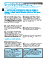
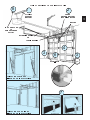
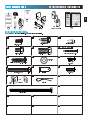
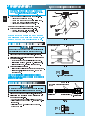
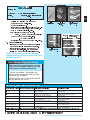
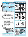
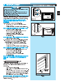
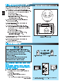
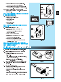
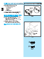
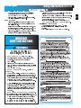
3507535556
GPS-IC Series
PMX-IC B Series
Automatic
Chain Drive/Belt Drive
Garage Door Operator
System
Complete with
and SERIES II Electronics
Remote Control
Operator MUST be installed with the included SERIES II Wall Control!
Self-diagnostic Electronic Sensory Protection System
(SAFE-T-BEAM SYSTEM) MUST Be Installed To Close Door!
Owner’s Manual
Customer Service
SAVE FOR FUTURE REFERENCE
CALL: 1-800-354-3643
V I S I T : W W W. G E N I E C O M PA N Y. c o m
AUTOMATIC GARAGE DOOR OPERATOR SYSTEMS
HANG MANUAL NEAR YOUR WALL CONTROL
TABBLE OFF CONTTENTS
SECTIION
PAGE
SAFETYY INFOORMATIION . . . . . . . . . . . . . . . . . . . . . . . . . . . . . . . . . . 2-44
PARTS IDENTIFIICATIONN . . . . . . . . . . . . . . . . . . . . . . . . . . . . . . . . . 5-66
ASSSEMBLLY
1 OPERATOR ASSEMMBLY . . . . . . . . . . . . . . . . . . . . . . . . . 10-111
1A Chaannel and Power Head Assseemblly . . . . . . . . . . .100
1B Rail and Poweer Heaad Assembbly . . . . . . . . . . . .10-111
INNSTALLLATIION
2 DETERMINE DOOR TYPE AND MOUNTING METHOD . . . 11
2A Installation on Track Guided Doors . . . . . . . . . 12-14
2B Installation on Trackless Doors . . . . . . . . . . . . 15-17
3 SAFE-T-BEAM® (STB) SYSTEM INSTALLATION . . . . . 18-19
Self-diagnostic “STB” System Troubleshooting . . . . 19
4 WAALL CONTTROL INSSTALLATTION . . . . . . . . . . . . . . . . . . . . 200
5 CONNECTT OPERRATOOR TO POWERR . . . . . . . . . . . . . . . . . . 211
6 MAIN LIMIT SWWITTCH SEETTTINGGS . . . . . . . . . . . . . . . . . . . . . 222
OPPERATIOON
7 FORCE ADDJUUSTMENT . . . . . . . . . . . . . . . . . . . . . . . . . . . . . 233
Conttactt Reverrse . . . . . . . . . . . . . . . . . . . . . . . . . . . . . . . 233
8 FINE LIMIT SWITTCH ADJUSTTMENTTS . . . . . . . . . . . . . . . . . 244
9 REMOTE CONTROLS . . . . . . . . . . . . . . . . . . . . . . . . . . . 24-25
10 BATTERY & VISOR CLIP INSTALLATION . . . . . . . . . . . . . 25
11 LIGHHT BULB AND LEENS INSTALLLATTION . . . . . . . . . . . . . . 266
MAIINTEENANCE . . . . . . . . . . . . . . . . . . . . . . . . . . . . . . . . . . . . . . . . . .277
TRROUBBLESHHOOTIING GUIDDE . . . . . . . . . . . . . . . . . . . . . . . . . . . . . . 288
WIRRING DIIAGRRAMM . . . . . . . . . . . . . . . . . . . . . . . . . . . . . . . . . . . . . . . 299
ACCESSSORIES . . . . . . . . . . . . . . . . . . . . . . . . . . . . . . . . . . . . . . . . . .300
WARRANTY . . . . . . . . . . . . . . . . . . . . . . . . . . . . . . . . . . . . . . . . . . . . .322
PRE-INSTALLATION CHECK LIST
FORR HELP-11.8800.3554.336433 OR GEENIIECCOMPPANYY.CCOM
Things to consider if you are planning to “do-it-yourself.”
2
Whether you are replacing an existing garage door operator or installing an operator in
your garage for the first time, there are some pre-installation issues which need to be
addressed. They are as follows:
The Genie Company recommends that you read and fully understand all
infforrmatiion and innstrucctionns conttainned hereinn beeforre choosinng a “Do-It-Yooursself ”
installation. Any questions should be directed to the Genie Company or an authorized
Genie Dealler.
(The issue numbers below refer to the circled numbers in the illustrations on page 3.)
Check your ceiling where the power
You need a 110-120 Volt power supply
head of your new unit will be mounted
available. If you plan to plug the unit into a
1
Plan how you will be mounting the power head
It is possible that ceiling joists may not be in the
exact position needed with respect to the garage
door operator In any case it may be necessary
to add an additional bracket and fasteners (not
included with your new door operator kit)
the wall directly above the garage
door.
2 Check
The door operator’s header bracket
must be securely fastened to this wall Insure
that the structure will provide a strong mounting
location
to see if the mounting location
3clearCheck
for the Safe-T-Beam System STB is
from obstruction and has a wood
®
(
5
standard electrical outlet is one available? The
outlet should be no more than about 3 feet from the
power head once it is mounted (The cord is 4 ft in
length ) SEE WARNING BELOW
avoid damage to your door and/or
6locksTooperator,
make sure you disable any door
prior to installing your operator.
)
surface available for attaching the STB brackets. The brackets may also be attached to concrete if necessary but extra tools and special
fasteners (not supplied) will be required
NOTE: 1-1/2" “STB” bracket adapters are
available through your local Genie Dealer.
that your door is properly balanced
7 Insure
and moving freely. SEE WARNING BELOW
Is your garage door made of
light-weight steel, aluminum, fiberglass
or glass panels? Additional support bracing
must be added to these type doors If this is the
case please contact the door distributor or
manufacturer so that they can furnish you with a
“bracing kit ”
garage does not have
door,
8 a separate entryIf your
4
WARNING
DO NOT USE EXTENSION CORD!
Extension cords can cause dangerous
overheating conditions.
DO NOT USE PORTABLE GENERATOR!
This product is designed to operate on
standard house current. Do not use
alternate power supplies.
(NOT SHOWN)
you might want to
consider an emergency release kit (GER-2) for
installation on your garage door See page 30
WARNING
If your door sticks, binds, or is out of
balance, have it adjusted by a professional.
Door springs, cables, pulleys, brackets and
associated hardware are under extreme
tension and can cause serious injury or
death.
5
TYPICAL SECTIONAL DOOR INSTALLATION
1
TYPICAL
SUPPORT
BRACKET
2
ADDED
HEADER BRACKET
MOUNTING BOARD
BRACES
36” POWER CORD
TO
120V GROUNDED
OUTLET
EXTENSION SPRING
OR
TORSION SPRING
3
4
6
3
SAFE-T-BEAM®
TYPICAL (TRACKLESS)
1-PIECE DOOR INSTALLATION
7
TYPICAL (TRACK GUIDED)
1-PIECE DOOR INSTALLATION
SECTIONAL DOOR
ONE-PIECE DOOR
3
SAAFETTY INNFORRMAATIO
ON
OVERVIEW OF
POTENTIAL HAZARDS
4
Garage doors are large, heavy objects that move with the help of springs
under high tension and electric motors. Since moving objects, springs under
tension, and electric motors can cause injuries, your safety and the safety of
others depend on you reading the information in this manual. If you have
questions or do not understand the information presented, call your nearest
service representative
In this section and those that follow, the words Danger,Warning, and Caution
are used to emphasize important safety information.
The word:
DANGER means that severe injury or death will result from failure
to follow instructions.
WARNING means that severe injury or death can result from failure
to follow instructions.
CAUTION means that property damage or injury can result from failure
to follow instruction.
The word NOTE is used to indicate important steps to be followed
or important considerations.
POTENTIAL EFFECT
PREVENTION
HAZARD
MOVING
DOOR
ELECTRICAL
SHOCK
HIGH
SPRING
TENSION
WARNING:
Can Cause
Serious Injury
or Death
Keep people clear of opening while door is
moving.
Do Not allow children to play with the door
operator.
Do Not operate a door that jams or one that
has a broken spring.
WARNING:
Can Cause
Serious Injury
or Death
Turn off power before removing operator cover.
When replacing cover, make sure wires are not
pinched or near moving parts.
Operator must be properly grounded.
WARNING:
Can Cause
Serious Injury
or Death
Do Not try to remove, repair or adjust springs
or anything to which door spring parts are
fastened, such as, wood blocks, steel
brackets, cables or other like items.
Repairs and adjustments must be made by a
trained service person using proper tools and
instructions.
SAFETY FEATURES (varies by model)
OPERRATOR INSTTALLATION
IMPORTANT
INSTALLATION
INSTRUCTIONS
WARNING:
Toreduce the risk of
severe injury or death:
1. READ AND FOLLOW ALL SAFETY, INSTALLATION AND
OPERATION INSTRUCTIONS. If you have any questions or
do not understand an instruction, call your service
representative.
2. Do Not install operator on an improperly balanced door. An
improperly balanced door could cause severe injury. Repairs
and adjustments to cables, spring assembly, and other
hardware must be made by a trained service person using
proper tools and instructions.
3. Remove all ropes and disable all locks connected to the
door before installing operator.
4. Install door operator 7 feet or more above the floor. Mount
the emergency release knob 6 feet above the floor.
5. Do Not connect the operator to the source of power until
instructed to do so.
6. Locate the control button:
• Within sight of door.
• At a minimum height of 5 feet, so small children cannot
reach it.
• Away from all moving parts of the door.
7. Install the entrapment WARNING label next to the wall
button or console. Install the emergency release tag on, or
next to, the emergency release
8. The operator must reverse when the door contacts a 1-1/2
inch high object on the floor at the center of the doorway.
This is about the size of a 2” x 4” board laid flat.
Safe-T-Beam® (STB) Non-Contact Reversing System
Places an invisible beam across door opening that reverses the door during down travel to the fully open
position if anything passes through beam
Safe-T-Reverse® Contact Reversing System
Automatically stops and reverses a closing door within 2 seconds of contact with an object
Safe-T-Stop® Timed Reversed System
Automatically opens a closing door if door does not close within 30 seconds
Force Guard® Control
Used to set the force required for opening and closing door For maximum safety set the minimum force
required to fully open and close door
Automatic Lighting System
One or two light bulbs (depending on model) up to 100 Watts max each are used for safer entries and exits
The light turns on when door is activated and automatically turns off 4 5 minutes later
Manual Emergency Release
Allows the garage door to be opened or closed manually for emergencies or maintenance
PARTS IDENTIFICATION
FORR HEELP-1..8000.3544.3643 ORR GENNIECOM
MPANY..COM
M
106
5
125
105
124
104
101
remotes
(vary by mode)l
126
100
103
NOTEE: Acccessories varyy by model.
FASTENERS - Shown full size. See Parts List for description.
69
112
127
96
Bolt, #10-24 x 1/2”
Bolt, 5/16”-18 x 1/2”
91
92
128
1/4”-20 x 3/4”
Self-Drilling Screw
Insulated Staple
Wall Control Screw
Bolt, 3/8”-16 x 7/8”
10
Nut, 3/8-16
79
81
Phillips Hex Head Screw, No. 10 x 1-1/4”
Lag Screw, 1/4” x 2”
90
89
9
Clevis Pin
N/A
OR
82
Speed Nut
Cotter Pin
N/A
Cold Head Pin
N/A
N/A
N/A
N/A
N/A
N/A
Pan Head Screw #6 x 1-1/4”
Pan Head
Phillips Screw
No. 8 x 5/8”
Hex Head Screw
No. 8 x 3/4”
PARRTSS IDDENTIFFICAATIION
FORR HEELP-1..800.3544.33643 ORR GENNIECOM
MPANY..COM
M
Stealth Power Head
6
6
5
19
16
7
12
4
17
12
12
3
11
15
14
18
12
19
2
21
3
20
26
1
22
23
13
39
24
12
40
12
36
34
38
11
10
35
37
27
25
29
9
8
28
33
26
26
32
31
Combined Parts List
Item
1
2
3
4
5
6
7
8
9
10
11
12
13
14
15
16
17
18
19
20
Part Name
Lens
Front Cover
Side Cover (by series/model)
Top Plate Assembly
Strain Relief
Cord & Plug Assembly
Component Panel (by series/model)
Bottom Cover
Screw, #8 x .75 Phil Hx Hd/W Sf Tap
Screw, #8 x .62 Phil Pan Hd/W Sf Tap
Screw, #8 x .50 Slt Hx Hd/W Sf Tap
Screw, #8 x .38 Slt Hx Hd/W Sf Tap
Light Socket (by series/model)
Terminal Block & Lug
M.O.V. Assembly
Receiver Assembly
Limit Set Switch
Sequencer Assembly
Screw, #6 x .38 Slt Hx Hd/W Sf Tap
Transformer Assembly (by series/model)
Item
21
22
23
24
25
26
27
28
29
30
31
32
33
34
35
36
37
38
39
40
30
Part Name
Rectifier Board Assembly
Fuse (F1), UL
Fuse (F2), UL
Limit Gear Shroud
Motor Bracket
Screw, #10 x 3/8” HH
Limit Plate/Pin Assembly
Limit Switch
Screw,#4 40 x 5/8” Slot HH w/Wshr,SfTap
Motor Assembly
Motor Adapter Plate
Screw, 1/4"-20 x 1/2” Slt HH w/Wshr
Limit Worm Gear
Limit Gear Bushing
Limit Worm Drive
Limit Worm Shim
Limit Wheel
Retaining Ring
Limit Cam
Limit Pinion, 8 tooth
Item
41
42
43
44
45
46
47
48
49
50
51
52
53
54
55
56
57
58
59
60
Part Name
Capacitor
Capacitor Clamp
Screw, #10-24 x 1/2”, Slot HH Sf-Tap
Nut, #10-32, Hex Serrated Flange
Circuit Board
C.B. Bracket
Circuit Board Mount
Screw, #10-16 x 5/8”, HH Sf Tap
Top Gear Housing
Middle Gear Housing
Bottom Gear Housing
Drive Shaft Bushing
Drive Thrust Washer
Drive Shaft
1/2” Retaining Ring
Main Drive Worm Gear
Optical Interrupt Wheel
Motor Flanged Bushing
Motor Thrust Washer
Poly Thrust Washer
PARRTSS IDDENTIFFICAATIION
FORR HEELP-1..800.3544.33643 ORR GENNIECOM
MPANY..COM
M
PRO-MAX Power Head
6
12
5
3
7
12
47
7
12
12
45
11
48
12
46
2
42
12
10
4
39
41
25
40
37
12
52 64
43
49
13
53
33
1
11
9
3
65
35
12
50
63
28
54
55
56
53
52
51
62
59
58
30
44
59
60
59
58
57
61
8
Item
61
62
63
64
65
Part Name
Main Drive Worm
Screw, #8 x 3-1/8” Slot HH, Sf Tap
Limit Switch Plate
Screw, #6 x 3/8” Phillips w/Wshr, Sf Tap
Screw, #4 x 5/8”, Slot HH w/Wshr, Sf Tap
PARRTSS IDDENTIFFICAATIION
FORR HEELP-1..800.3544.33643 ORR GENNIECOM
MPANY..COM
M
Channel
8
67
68
69
67
70
69
71
72
71
71
98
83
71
84
66
73
85
74
86
97
89
87
88
75
71
99
76
77
71
90
78
83
92
79
80
94
93
91
79
96
82
89
95
Combined Parts List
Item Part Name
Item Part Name
66 Belt & Bullet Assembly - 7’6” Door
72 Channel - 7’6” Door (128” LG)
(Belt Models Only)
Channel - 8’ Door (146” LG)
Belt & Bullet Assembly - 8’ Door
Channel - 10’ Door (170.75” LG)
(Belt Models Only)
Channel - 12’ Door (188” LG)
Belt & Bullet Assembly - 10’ Door
73 Pulley (Chain Models Only)
(Belt Models Only)
Pulley (Belt Models Only)
Belt & Bullet Assembly - 12’ Door
74 Carriage Bolt, 5/16”-18 x 4.0
(Belt Models Only)
75 Carriage Pin, 5/16” x 1.25
67 Sprocket Bushing
76 Pulley Bracket Assembly
68 Sprocket, 10 Tooth - 7’6” & 8’ Doors
77 End Bracket
(Chain Models Only)
Sprocket, 12 Tooth - 10’ Door
78 Hex Flange Nut, 5/16”-18 (Chain Only)
(Chain Models Only)
Flat Washer (Belt Models Only)
Drive Sprocket, 18 Tooth - 7’6” & 8’ Doors
(2)Hex Jam Nut, 5/16-18 (Belt Models Only)
(Belt Models Only)
79 Lag Screw, 1/4” x 2” Hx Hd/W
Drive Sprocket - 10’ Door
80 Header Bracket
(Belt Models Only)
81 Speed Nut
69 Screw, #10-24 x .50 Hx Hd
82 Cold Header Pin
70 Sprocket Bracket (Chain Models Only)
83 Carriage Stop
Sprocket Bracket - 7’6” & 8’ Doors
84 Roller Chain -7’6” Door (Chain Only)(242.5”)
(Belt Models Only)
Roller Chain-8’ Door (Chain Only)(278.5”)
Sprocket Bracket - 10’ Door (Belt Only)
Roller Chain -10’ Door (Chain Only)(328.5”)
Sprocket Bracket - 12’ Door (Belt Only)
71 Screw, #10-24 x .38 Hx Hd/W
8mm Belt
90
Item Part Name
85 Chain Bullet
Belt Bullet
Belt Retainer
Screw, #6-32 x 1/2” Phil Pan Hd Slf Tap
86 Carriage Slide
87 Emerg. Release Cord-7’6” Doors(26.5”)
Emergency Release Cord 8’ & 10’ Doors(56.5”)
Emergency Release Cord -12’ Doors(96.0”)
88 Emergency Release Knob (Red)
89 Cotter Pin
90 Clevis Pin
91 Screw, 3/8”-16 x .87 Hx Hd Mch
92 Hex Nut, 3/8”-16
93 Curved Door Arm
94 Straight Door Arm
95 Door Bracket
96 Screw, 1/4”-20 x 3/4” Hx Hd, Sf Tap
97 Carriage Assembly
98 Carriage Cap
99 Screw, #10-14 x 1-5/16” Hx Hd
100 Wall Console (Series II )
101 Wall Button (Series II ) (lit primary)
Wall Button (unlit secondary)
81
PAARTS IDEENTTIFICCATIONN
FOR HELP--1.800..3554.36443 OR GENIEECO
OMPANY.CO
OM
Rail
9
118
111
81
119
73
110
80
82
76
121
117
68
79
112
116
120
69
89
123
122
90
97
115
87
114
86
94
88
79
96
91
95
89
92
93
Item
102
103
104
105
106
Part Name
Boom Support Kit (not shown)
Safety & Maintenance Guide
Emergency Release Tag (Tri L)
Entrapment WARNING Label
Wire
110
111
112
113
114
115
116
117
118
119
120
121
122
123
124
Rail (L=112.475”)
Screw, 5/16”-18 x 3/4”
Screw, 5/16” x 1/2” HH w/Wshr
Pulley Support
Chain
Sprocket Saddle
Screw, 5/16”-18 x 2-1/4” HH
Bolt Retainer
Screw, 5/16”-18 x 1-1/8” HH
Large Pulley Bushing
Square Nut, 5/16”-18
Screw, 1/4”-20 1” HH
Hex Nut/Lockwasher, 1/4”-20
5/16-18 Lock Nut
STB System Sensor (Green LED)
90
Item
125
126
127
128
Part Name
STB System Source (Red LED)
STB Mounting Brackets (2)
Screw, 1-1/4” Phillips HH
Insulated Staples
113
1...OPERATOR ASSEMBLY
OPEN BLUE PARTS BAG
Screws for attaching light cover are included in this
bag. Please set aside for use later.
1. Attach emergency release knob cord (Fig. 1-1).
• Tie overhand knot in end of cord.
10
• Thread cord through knob so knot is inside knob.
• Thread cord through hole in carriage lever.
• Tie overhand knot in other end of cord.
Do Not cut cord until after power head is mounted.
2. Attach emergency release tag (Fig. 1-1).
• Thread wire through hole in carriage lever.
• Wrap wire around itself, tie securely.
PLEASE NOTE THE ASSEMBLY PROCEDURES
ARE DIFFERENT FOR RAIL AND CHANNEL. BE
SURE TO FOLLOW THE APPLICABLE STEPS.
CHANNEL & POWER HEAD ASSEMBLY
CAUTION
FOR HELP--1.800..3554.36443 OR GENIEECO
OMPANY.CO
OM
Toward Door
Toward Power Head
Carriage
Emergency
Release
Tag
Emergency
Release
Cord
Emergency
Release
Knob
Fig. 1-1
[69] Hex Head Screws
“D” -Shaft and Hole
Do Not attempt to run power head or to set limits until
operator is fully assembled and attached to the door.
3. Place power head and channel on clean,flat surface.
4. Slide drive end of channel down over “D”-shaft on top of
power head (Fig.1-2).
Support header end of channel level with power head.
Slide carriage to align “D”-shaft with “D”-hole in sprocket.
Slide channel down “D”-shaft flush with power head.
5. Fasten channel to power head .
• Align mounting holes in front and rear of power head frame.
• Insert and securely tighten the four (4) No.10 x 1/2” hex
head screws [69].
•
•
•
Fig. 1-2
[69]
NOOTE: Chain innerr-sslidee or belt buullett shoould rem
mainn at
mid--traavel when assemblingg to power head to providee propeer
trraveel whhenn setttiing limits.
RAIL & POWEER HEAD ASSEMBLY
CAUTION
Do Not attempt to run power head or to set limits until
operator is fully assembled and attached to the door.
3. Place power head and rail on clean, flat surface.
4. Slide drive end of rail down over “D”-shaft on top
of power head (Fig. 1-3).
•
•
•
Support header end of rail level with power head.
Slide carriage enough to align “D”-shaft with “D”-hole
in sprocket.
Slide rail down “D”-shaft flush with power head.
drags on the rail
No. 10 x 1/2” Hex Head Screw
[69] No. 10-24 x 1/2 Hex Head Screws
”
[112] 5/16 x 1/2 Hex Head Screws
”
”
Sprocket Saddle
Carriage Stop
“D” -Shaft and Hole
Fig. 1-3
[112]
5/16” x 1/2” Hex Head Washer Screw
5. Fasten rail to power head.
• Align mounting holes of sprocket saddle, rail
and power head frame.
• Insert the two (2) 5/16” x 1/2” hex head
screws[112], then two (2) No. 10-24 x 1/2” hex
head screws [69].
• Tighten screws.
NOTE: Innerr-slidde/bulllet shhould remaiin att miid-travel
whenn asseembliing to powerr headd to provide proper
traveel whhen settting limiitss.
11
Adjusting
Bolt
6. Use adjusting bolt to set chain tension (Fig. 1-4)
• Chain should sag slightly but not so much that it
drags on the rail.
Fig. 1-4
OPEN ORANGE PARTS BAG
2... INSTTALLAATIONN
IMPORTANT
INSTALLATION
INSTRUCTIONS
WARNING:
Toreduce the risk of
severe injury or death:
1. READ AND FOLLOW ALL SAFETY, INSTALLATION AND
OPERATION INSTRUCTIONS. If you have any questions or
do not understand an instruction, call your service
representative.
2. Do Not install operator on an improperly balanced door. An
improperly balanced door could cause severe injury. Repairs
and adjustments to cables, spring assembly, and other
hardware must be made by a trained service person using
proper tools and instructions.
3. Remove all ropes and disable all locks connected to the
door before installing operator.
4. Install door operator 7 feet or more above the floor. Mount
the emergency release knob 6 feet above the floor.
5. Do Not connect the operator to the source of power until
instructed to do so.
6. Locate the control button:
• Within sight of door.
• At a minimum height of 5 feet, so small children cannot
reach it.
• Away from all moving parts of the door.
7. Install the entrapment WARNING label next to the wall
button or console. Install the emergency release tag on, or
next to, the emergency release.
8. The operator must reverse when the door contacts a 1-1/2
inch high object on the floor at the center of the doorway.
This is about the size of a 2” x 4” board laid flat.
FOR HELP-1..8000.354..36643 OR GENIECOM
MPAANY.COM
M
WHAT TYPE OF DOOR DO YOU HAVE?
Look at the drawings below. They tell you where
to find the installation instructions you need
Track Guided Doors
SEE SECTION 2A
Section Door With
Curved Track Hardware
Curved
Track
with
Vertical
Section
1-Piece Door With
Horizontal Track Hardware
Straight Track
(Horizontal Only)
“H”
“H”
DOTTED LINE AT “H”
INDICATES HIGHEST
POINT OF TRAVEL
Trackless Doors
SEE SECTION 2B.
1-Piece Door
Jamb Type Hardware
(No Track)
“H”
1-Piece Door
Pivot Type Hardware
(No Track)
“H”
Alternatee Mouuntingg Meethodds
NOTE: Materials for mounting are not included
Angle Iron Method
Conduit Method
12
2A... FORR TRRACK GUUIDED DOORRS
– FOR TRACKLESS DOORS GO TO PAGE 15 –
WARNING
•
•
•
Do Not try to remove, repair or adjust
springs or anything to which door spring
parts are fastened, such as, wood blocks,
steel brackets, cables or other like items.
Repairs and adjustments must be made by
a trained service person using proper tools
and instructions.
Handles and other door projections can
catch clothing. Remove ropes, hooks,
hangers, decorative or security items
mounted to door.
Be sure Emergency Release Cord does not
catch on roof carrier or other vehicle parts.
1. Establish center line of door and header (Fig. 2-1).
• Close door.
• Measure door width. Mark center.
• Use straight edge to draw vertical line “V.”
– down door about 6”.
– on top of door.
– up header about 20”.
2. Establish Header Bracket position (Fig. 2-2).
• Watch top edge of door as you raise it.
• Stop door when top edge reaches highest point
of travel.
• Measure distance from top edge of door to floor.
• Add 2-1/2” to this measurement.
• Close door.
• Mark header at this height.
• If door spring is in the way, mark header 2-1/2”
above the spring.
• Draw horizontal line “H” across line “V” at this
point (Fig 2-1).
NOTE: Heaaderr brackket muust be att leaast 2--1/2” abovee
high poinnt of door travvel.. It cann be insttalleed higherr if
door sppring is in the waay.. Doo Nott moove the sprinng.
Line “V”
(Vertical Center Line
of Door)
Line “H” Can Be
Drawn Above
Spring
Line “H”
Door
Header
Inside of Door
Fig. 2-1
NOTE: Line “H” Can Be
Drawn Above Spring
Spring
Mark
Header
Here
Or
Above
Spring
Line “H”
Add 2-1/2”
Minimum
High Point
Of Door Travel
Door Track
Header
Door
Measure To Floor
Fig. 2-2
CAUTION
Header bracket must be fastened to garage
framing. Do Not fasten to drywall, particle
board, plaster or other such materials.
3. Install header bracket (Fig. 2-3)
• Place bracket so:
– center hole is on line “V.”
– all holes are on line “H.”
• Mark hole positions “A” and “B.”
• Drill 5/32” holes at marked positions.
• Fasten bracket to header using two (2) 1/4” x 2”
lag screws [79].
4. Attach channel/rail assembly to header
bracket (Fig. 2-4).
• Fasten header end of the channel/rail to the
Header bracket with cold header pin [82].
• Install speed nut [81].
• Support power head above floor, use:
– rope.
– ladder with cardboard packing.
– wood.
5. Level rail assembly and power head (Fig. 2-5).
• Raise and support power head above door tracks.
• Open door.
• Level channel/rail assembly and
support temporarily.
• Center channel/rail assembly and power head
on line “V” of door.
NOTE: The channel/rail assembly and power head
should be level if possible. If necessary, power
head may be mounted lower. However mounted,
moving door must not touch channel/rail assembly.
CAUTION
Line “V”
“B”
Header Bracket
“A”
Line “H”
13
Vertical
Centerline
of Door
Lag Screws
Fig. 2-3
T-rail shown. Channel
attachment is same.
Speed nut
[81]
Header
Bracket
Doors made of masonite, lightweight wood, fiberglass, and metal must be properly braced before
mounting Door Operator.
Contact door manufacturer or distributor for bracing
instructions.
[82]
Cold header
pin
Spring
Header
Door
Mounting bracket must be fastened to garage
framing. Do Not fasten to drywall, particle board,
plaster or other such materials.
6. Mount power head
(See Section 2 MOUNTING METHODS).
• Be sure channel/rail assembly and power head
are on door center line (Line “V”).
• Check the illustrations. Decide which mounting
method you will use. Materials for mounting are
not included.
• After power head is installed, remove
supporting material.
• Close door.
7. Install door braces (See CAUTION below).
CAUTION
[79]
Support if
necessary to
clear spring
Fig. 2-4
Power Head
Channel/Rail
Assembly
Center Line
Fig. 2-5
“V”
Top of Door
14
“V”
Top of Door
Top of Door
de la ort
orte
OR
“V”
“V”
[96]
“V”
[79]
[96]
Sectional doors
[96]
[79]
9. Install door arms (Fig. 2-7).
• Attach straight door arm to carriage.
– slip straight door arm into slot at bottom of
carriage as shown.
– secure with clevis pin [90] and cotter pin [89] .
• Attach short end of curved door arm to door
bracket as shown.
– slip short end of curved door arm into slot in
door bracket.
– secure with clevis pin and cotter pin.
• Release carriage (See emergency release tag).
– slide carriage towards closed door.
– stop carriage 14” minimum from door.
10. Join door arm sections (Fig. 2-8).
• Use two (2) 3/8” x 7/8” hex bolts [91], and hex
flange nuts [92].
– use any two holes as far apart as possible.
– slide carriage back and forth as needed to
align holes.
• Tighten hex nuts securely.
11. Adjust emergency release cord length.
• Mount the emergency release knob 6 feet from
the floor.
• Retie overhand knot and trim excess cord.
DO NOT plug power cord into outlet.
Go to Section 3-SAFE-T-BEAM®
SYSTEM INSTALLATION.
– PROCEED TO PAGE 18 –
[79]
One-piece doors
Fig. 2-6
[96]
8. Install door bracket (Fig. 2-6).
• Contact door manufacturer.
NOOTE: Sellf-ddrilliing screwss arre intennded for use with
light-weight door only, while lag screws are meant
for wood doors only.
Becauuse door desiigns varry, moodifiicaations may
be reequiredd and addditionall matterials needded. Plleasse
contacct your door manufactturer witth any questions
concerninng your doorr.
OPEN YELLOW PARTS BAG
“V”
1/4”-20 x 3/4” Self-Drilling Screw
[79]
1/4” x 2” Lag Screw
14” MIN.
Clevis pin
Cotter pin
[90]
[90]
[89]
Clevis pin
Straight door arm
Curved door arm
Fig. 2-7
[89]
Straight door arm
[91]
Cotter pin
Bolt,
3/8-16 x 7/8”
[92]
Curved door arm
3/8-16 nut
Fig. 2-8
[ ]
[92] 91
Nut, 3/8-16
Bolt, 3/8”-16 x 7/8”
2B... FOR TRACKLESS DOORS
WARNING
Do Not try to remove, repair or adjust springs or
anything to which door spring parts are fastened,
such as, wood blocks, steel brackets, cables or
other like items.
Repairs and adjustments must be made by a
trained service person using proper tools
and instructions.
• Handles and other door projections can catch
clothing. Remove ropes, hooks, hangers,
decorative or security items mounted to door.
• Be sure emergency release cord does not catch
on roof carrier or other vehicle parts.
1. Establish center line of door and header (Fig. 2-9).
• Close door.
• Measure door width. Mark center.
• Use straight edge to draw vertical line “V.”
– down door about 6.”
– on top of door.
– up header about 20”.
2. Determine door rise (Fig. 2-10).
• Open door to highest point of travel.
• Measure distance from top of door to floor.
• Subtract the actual height of door. The remainder
is the door rise in inches as shown in TABLE A.
•
TABLE A
Door rise
in inches
Up to 4”
4” to 8”
8” to 12”
Line “V”
(Vertical centerline of door)
Door header
CAUTION
Header bracket must be fastened to garage
framing. Do Not fasten to drywall, particle board,
plaster or other such materials.
4. Install header bracket (Fig. 2-11).
• Place header bracket so,
– center hole is on line “V.”
– all holes are on line “H.”
• Mark hole positions (“A” and “B”).
• Drill 5/32” holes at marked positions.
• Fasten header bracket to header with two (2)
1/4” x 2” lag screws [79].
Top of door
Line “H”
Inside of door
Fig. 2-9
Door rise
Locate header bracket above
top edge of CLOSED door
Up to 10”
10” to 15”
15” to 20”
3. Locate header bracket (Fig. 2-9).
• Use TABLE A to determine header
bracket position.
• Draw horizontal line “H” across line “H” at
this point.
See
TABLE A
Highest point
of travel
Highest point
of travel
Floor
Door rise
Floor
Fig. 2-10
Line “V”
“B”
Header bracket
“A”
Line “H”
Vertical centerline
of door
Lag screws
Fig. 2-11
[79]
15
5. Install door braces
(See CAUTION below).
CAUTION
16
Doors made of masonite,
lightweight wood, fiberglass,
and metal must be properly
braced before mounting
an operator.
Contact door manufacturer
or distributor for
bracing instructions.
“V”
“V”
Top of Door
Top of Door
de la rte
OR
“V”
[96]
[96]
[79]
“V”
[79]
Fig. 2-12
6. Install door bracket (Fig. 2-12).
Header bracket
• Contact door manufacturer for proper installation.
NOOTE: Sellf-ddrilliing scrrewss arre intennded for use with
ligght-weeight door onlyy, whhile lag sccrewws arre meaant
Channel
foor wood doors only.
Becauuse door desiigns varyy, modiificaatiions may
be reequiredd and addditionall matterials needded. Plleasse
contacct your door maanufaactturer witth any quesstions
Header
concerninng your door..
Rail
Door
bracket
7. Attach channel/rail assembly to header
bracket (Fig. 2-13).
• Fasten header end of the channel/rail to the
header bracket with pin.
Door
• Install speed nut onto pin (Fig, 2-14).
• Place cardboard packing under power head. Use
additional support if needed.
Power head
(Protected by cardboard
8. Establish power head mounting height (Fig. 2-15).
or packing)
• Power head should be at door height above floor
or higher.
Fig. 2-13
• Temporarily support power head in this position.
Use
Door
br ket
– rope.
– ladder with cardboard packing.
– wood.
Same arrangement applies
to channel (not shown)
[81]
Speed
nut
[82
]
Pin
Fig. 2-14
Critical height is point where the rail/channel attaches to power head.
CORRECT
WRONG
r
Door height
Fig. 2-15
OPEN YELLOW PARTS BAG
Str
CAUTION
d_39905_38124_14.0
fr
[91]
Bolt, 3/8-16 x 7/8”
ket m
ge
Do Not fasten to drywall, particle board,
9. Mount po
TERNATE
MOUNTING METHODS).
• Be sure rail assembly and power head are on
door center line (line “V”).
• Check the illustrations. Decide which mounting
method you will use. Materials for mounting are
not included.
• After power head is installed, remove
supporting material.
• Close door.
10.
xactly as shown (Fig. 2-16).
• Overlap arms by two (2) holes.
• Install two (2) 3/8” x 7/8” hex bolts, and hex
flange nuts.
• Tighten hex nuts securely.
11. Install assemb
2-17).
• Attach straight end of assembled door arms to
door bracket.
– slip straight door arm into slot in door bracket.
– secure with clevis pin [90] and cotter pin [89].
• Release carriage (See emergency release tag).
• Slide carriage toward door.
• Attach short end of curved door arm to carriage.
– slip curved door arm into slot in carriage.
– secure with clevis pin and cotter pin.
Cur
[92]
3/8-16 nut
Fig. 2-16
Clevis pin
[90]
[89]
Fig. 2-17
[ ]
[92] 91
Nut, 3/8-16
NOTE:: When openning, door muust not passs levvell
posiitiion or if yoou are not abble to cllose the dooor after
coomplettinng previious sttep; a loonger door arrm is
reqquiredd. Ann exttensioon kit caan be purchassedd by
caalliing the Custtomer Seerviice phone number,
1..8000..3554..3643.
12. Adjust emergenc
d length.
• Mount the emergency release knob 6 feet from
the floor.
• Retie overhand knot and trim excess cord.
[90]
Clevis pin
[89]
Cotter pin
Bolt, 3/8”-16 x 7/8”
17
3... SAFE--T-BEAM
INSTAALLAATIONN
WARNING
FOR HEELPP-1..8000.354..36643 ORR GENNIECOM
MPAANY..COM
M
®
e-T-Beam® System
If you have plugged in the po
d
—UNPLUG
IT
NOW.
18
NOTE: The operator will not close the door
automaticcallly unlesss the Safe--T-Beaam® System
m
is innstallledd.
1.
kets.
• Mark both sides of garage door frame or wall 5”
above floor (Fig. 3-1).
• Hold bracket against door frame or wall.
– Check if brackets extend out from wall far
enough, so tongue of bracket is beyond door,
tracks or any door hardware.
– If not:
a. STB bracket extensions are available at
local dealer.
b. Blocks of wood, etc. may be substituted
for extensions.
• Center bracket on your mark (Fig. 3-2).
• Fasten each with 2 screws [127].
[127]
FIG.
.
tongue
br ket
FIG. 3-2
kets.
#10-16 x 1-1/4”
NOTE: Mountiing braccketts caan be atttachedd to the
floor usiing cooncrete anchors (nnot providedd).
2. Mounting STB source and sensor.
FIG. 3-3
Attaching STB’
kets
(See directions on next page and
Figure 3-4 before attaching.)
SUN
If garage has only one garage door.
– Determine which side of garage receives
most direct sunlight (Fig. 3-4).
– Red LED should always be on sunny side
whenever possible (Fig. 3-4).
• For multiple doors.
– Preventing crossed signals is critical.
– Place source and sensor modules on
adjacent doors facing in opposite directions
(Fig. 3-4).
•
RED
LED
GREEN
LED
RED RED
LED LED
RED
LED
GREEN GREEN
LED
LED
FIG. 3-4 STB locations.
Dashed Line = striped wire
Solid Line = white wire
.
Route wire using either method shown (Fig. 3-5).
Securely fasten wires to wall as you go.
– Use insulated staples (included).
[128]
GREEN
LED
RED RED
LED LED
THREE DOOR
GARAGE
OPEN RED PARTS BAG
•
•
GREEN
LED
TWO DOOR
GARAGE
ONE DOOR
GARAGE
NOTE:: Too hellp preevenntinnterrfereencefroom sun, STBB
sennsorrs (greeen LEED)) mayy bee plaaced furtherr awwayy
from the door opening wherre they willl spennd morre
tim
me in shhadoows..
• Slide source/sensor onto tongue of bracket
until it clicks into place (Fig. 3-3).
3.
GREEN
LED
Green
Source
Green
Red
Red
Source
Sensor
Sensor
Insulated staple
– Staples should be snug only.
A
Power
Head
FIG.
Power
Head
B
.
Staples whic
to stop wor
staples,
CAUTION
When using the insulated
ou fasten them only as tightly
ugly.
• Make wire attachments at STB’s.
– Splitting and stripping wire ends to be
connected as shown (Fig. 3-6).
– Loosen terminal screws.
– Insert wire under flat plate and tighten screw. It
does not matter which wire, white or striped,
goes on which terminal (Fig. 3-7).
• Make wire attachments at power head.
–
oMax. STB’s are connected to terminals
#2 and #3 on power head (Fig. 3-8).
–
. STB’s are connected to
terminals #3 and #4 on power head (Fig. 3-8).
4. Check the following.
• Insure that no part of door or its hardware is in
path between lenses of source and sensor.
• Insure that tops of lenses are between 5”-6”
above the floor (Fig. 3-9). The brackets are
flexible and can be adjusted slightly if needed.
2
3
FIG. 3-6
Splitting and
FIG. 3-7
Attachments
at STB.
FIG. 3-8 (ProMax)
Attachments at
po
.
top edge of lens between
5” - 6” above floor.
3
4
FIG. 3-8 (Stealth)
Attachments at
po
.
NOTE: STB alignment check must be performed
following connection to electrical power (see page 21).
DO NOT PLUG IN YET!
FIG. 3-9 Check lens height.
Safe-T-Beam ® Alignment Check
After turning the electrical power on, if the
STB’s are not in proper alignment, the red
LED (Source) will blink continuously.
To correct the problem – the brackets are
flexible and can be adjusted slightly to bring
the system into alignment.
When the STB’s are in alignment the red LED
will stop blinking and stay on.
STB SELF-DIAGNOSTIC TROUBLESHOOTING
SOURCE (RED LED) SENSOR (GREEN LED) INDICATED CONDITION
REQUIRED ACTION
ON
ON
NORMAL OPERATION
NONE REQUIRED
OFF
OFF
1.POWER HEAD NOT POWERED
2.WIRING FROM POWER HEAD BAD
OFF
ON
1.CHECK BREAKERS, FUSES, PLUGS
2.CHECK WIRING FOR OBVIOUS SHORTS
1.CHECK WIRING
2.REMOVE POWER AND REAPPLY
1.CHECK ALIGNMENT 2. CHECK FOR OBSTRUCTION
3.CALL CUSTOMER SERVICE
1.CHECK WIRING
2.CALL CUSTOMER SERVICE
1.ATTEMPT TO DETERMINE SOURCE OF INTERFERENCE
2.CALL CUSTOMER SERVICE
1.CALL CUSTOMER SERVICE
2.CALL CUSTOMER SERVICE
2 BLINKS, PAUSE (REPEAT)
ON
2 BLINKS, PAUSE (REPEAT)
OFF
3 BLINKS, PAUSE (REPEAT)
ON
4 BLINKS, PAUSE (REPEAT)
ON
1.WIRING TO SOURCE MISSING OR BAD
2.POWER HAS BEEN INTERRUPTED
1.BEAM NOT ALIGNED 2. BEAM OBSTRUCTED
3.SENSOR DEFECTIVE
1.WIRE TO SENSOR MISSING OR BAD
2.SENSOR DEFECTIVE
1.SENSOR RECEIVING INTERFERENCE
1.SOURCE NOT SENDING PULSES
2.SOURCE DEFECTIVE
NOTE: IF OPERATING PROBLEM EXISTS, THE DOOR CAN BE CLOSED IF YOU: 1. DISCONNECT THE STB SYSTEM FROM THE OPERATOR AND 2. HOLD WALL CONTROL BUTTON
DOWN UNTIL DOOR IS CLOSED. (REMOTE CONTROL & WIRELESS KEYPAD WILL NOT WORK WITHOUT STB)
CUSSTOM
MER SERRVIICE: 1..8000.3544.336433 or www.ggenieccom
mpaanyy.ccom
19
4... WALL CONTROL INSTALLATION
20
Po
or
FORR HELP-11.8800.3544.336433 ORR GEENIIECCOMPPANNY.CCOM
WARNING
Power head
terminals 1
d must be unplugged befor
hing
h each other
White
Striped
2
Wall
button
terminals
W
B
3
W1
Use of an
light not to wor
•
CAUTION
Y3
1
PUSH
TO SET
OPEN
L MITS
MENT
Striped
2
Wall
console
terminals
BW
Power
head
ferminals 3
Rear view of
power head
Back view
4
Fig. 4-1a
Power head
terminals
1
E:
CO
NO E
SW
ONL
BE
U E N Y
SER E
CON ROLS
DO N T
USH
L M T S
UN E S
D OR I
A T C E
Striped
White
2
NEC
LIM T
SET
OPEN
FOR E
CLO E
FOR E
RAD O
SIG AL
LEA N
CODE
OPEN
MORE
SE
OPEN
IMIT ADJUSTMENT
U S
Patent
o
5
2
B
Wall
button
terminals
Back view
3
3
4
EITHER
5
MORE
FORCE
1
5 243 784
21 869
2
Front USE
viewONofY
SERIES
II C
power
head
W
1
6
CLOSE
MORE
– Connect striped wires to terminal “2” on power
head and “B” on wall control.
– Connect white wire to terminal “1” Lon power
head and “W” on wall control.
Striped
White
BW
Wall
console
terminals
3
power head
NOT
terminals
Back view
Fig.54-1b
Wall console
CODE
Wall button
LIMIT
– Connect striped wires to terminal “1” MO
on Epower
head and “B” on wall control.
– Connect white wire to terminal “2” on power
head and “W” on wall control.
OR
4. Mount wall control (Fig. 4-2).
• Use two pan head screws.
5.
• Remove protective backing and stick near
wall control.
• Use tacks or staples to permanently mount Label.
• Make sure everyone reads and follows WARNINGS.
#6 x 1-1/4”
ws
Fig. 4-2
1
Vacation Locking Switch
– LOCK disables controls after door is completely closed
– UNLOCK allows controls to work normally
Independent Light Control
4
– Controls door operator lights from inside garage
– Energy-Saver shut-off turns off light 5 minutes after
door activation
NOTE: Additional wall controls are available from your
dealer. ONLY ONE OF YOUR WALL CONTROLS MAY BE
THE LIGHTED TYPE. If you have a lighted wall control, all
your additional controls must be un-lighted. More than one
lighted wall control per operator will cause a malfunction.
White
MORE
•
to malfunction. Dr
.
1.
om po
ol.
• Place the wall control:
– In sight of door.
– At least 5 feet from floor, so small children can
not reach it.
– Away from moving parts of door and
door hardware.
• Use staples to fasten wire to ceiling and wall.
2. Remove 1/2” insulation from eac
(Fig. 3-6)(pg. 19).
3. Attac
4-1a)
(MAX Fig. 4-1b).
• Loosen, but Do Not remove screw from terminal.
LO
OR
G4
ol will cause the
.
Back view
4
2
Lighted Button
– Shows system is powered
– Lights when Security Lock
2 Switch is in UNLOCK position
– Goes out when Security Lock
Switch is in LOCK position
Door Control Button
– Open and closes door from
inside garage
3
Fig. 4-3
5... CONNECT OPERATOR TO POWER
FOR HELLP--1.8000.3354.36443 OR GENIECOMPANY.COM
WARNING
To reduce the risk of electrical shock, this equipment
has a grounding type plug that has a third
(grounding) pin. This plug will only fit into a grounding
type outlet. If the plug does not fit into the outlet,
contact a qualified electrician to install the proper
outlet. Do Not change the plug in any way. The door
operator must be properly grounded to prevent
personal injury and damage to the components.
The ELECTRICAL POWER to the door operator
MUST BE TURNED OFF when power head cover is
removed. Electrical power must remain off while making electrical connections.
1. Check local building codes.
• Some building codes require direct wiring to a
branch circuit. If direct wiring is NOT required,
plug door operator into grounded outlet
(Fig. 6-1).
2. Return to Section 3 for SAFE-T-BEAM® System
alignment and troubleshooting.
NOTE: If permanent wiring is required, have a
professional electrician install circuit and wire
door operator.
PERMANENT WIRING INNSTRRUCTTIONSS FOOR ELEECTRIICIIAN
1. Disconnect the power cord from the branch
circuit mains.
2. Remove bottom cover from power head.
• Remove four (4) hex head screws from front
and rear covers.
• Slide bottom cover off.
3. Remove existing power cord from power head.
• Disconnect three power cord wires.
• Remove and discard power cord.
• Remove 7/8” diameter knock-out plug.
• Install a suitable entrance bushing.
4. Install permanent wiring to power head.
For Stealth—connect permanent wiring to
internal terminal block.
• Connect white supply line to silver terminal.
• Connect black supply line to brass terminal.
• Connect ground wire to green wire location
(GROUND).
For ProMax—connect permanent wiring.
• Make connections with UL recognized wire nuts.
• Connect white supply line to white wire.
• Connect black supply line to black wire.
• Connect ground wire to green wire location
(GROUND).
• Wires inside operator are to be a minimum of
6 inches.
5. Replace power head bottom cover.
• Replace and tighten four (4) hex head screws.
NOTE: Circuit boards are light sensitive. Make sure
cover is on power head before operation.
Grounded
outlet
Operator
power cord
Fig. 5-1
21
6... MAIN LIMIT SWITCH SETTINGS
FOR HELP-1.800.354.3643 OR GENIECOMPANY.COM
WARNING
Door opens rapidly.
• Keep path clear.
• Position ladder to the side of power head so it
22
is clear of all moving parts of door and
operator.
Set door operator so minimum force is needed
to operate door.
Before starting main limit switch settings, LOCK carriage onto rail assembly (See emergency
release tag).
1. Raise the door until the carriage engages with
the inner-slide/bullet.
2. Set “OPEN” limit switch (Fig 6-1).
• Locate limit set switch on back of power head.
• Push and hold limit set switch until door moves
to the fully open position.
– release the limit set switch.
– “OPEN” limit switch is set.
NOTE: If door stops and refuses to move up, adjust
“OPEN FORCE” (See Section 7-FORCE
ADJUSTMENT) and then repeat setting limit switch.
3. Set “CLOSE” limit switch (Fig. 6-1).
• Push and hold limit set switch until door contacts
the ground and stops.
– release limit set switch.
– “CLOSE” limit is set.
NOTE:: Iff door stops annd refusees to movee downn,
addjustt “CLOSEE FORRCE” (See Sectiion 7--FORCEE
ADJUUSTMEENT) annd thenn reppeat seetting limiit swwittch.
NOTE:: Do Not push the liimit seet swiitch aggain, your
liimits are set. Slight addjusttmeent may be neeededd laterr
(Seee Secttion 8--FINEE LIMIT SWITCH ADJJUSTMENTS).
1
PUSH
2
NEC
CLASS 2
3
4
TO SET
O EN
MORE
MORE
PUSH
C O E
CLO E
O EN
LIMITSC
TO SET
LIM TS
L MIT ADJUSTMENT
STEALTH
OR
SE ONLY
IE II CO
NEC
CLASS 2
NOTE
U E ONLY W TH
SER E
CON ROL
PUSH
BUT ON
1
COM
2
SAF TY
BEAM
3
DO N T
USH
L M T S
U LE S
D OR I
TT C E
5
CLOSE
MORE
CLOSE
E
OPEN
MORE
OPEN
IMIT ADJUSTMENT
S
MORE
FORCE
Patent No 5 243 784
5 221 869
PRO MAX
Fig. 6-1
5
6
4
6
LIM T
SET
OPEN
FOR E
CLO E
FOR E
RAD O
SIG AL
LEA N
CODE
SE
NLESS
DOOR IS
ATTACHED
LIMIT
SET
OPEN
FORCE
LOSE
E
MORE
FORC
7... FOORCEE ADJUSTTMEENT
FOR HELP-1.800..3554.36433 OR GENIEECOMPANY.CCOM
WARNING
Adjust your door operator so that minimum force
is needed to operate door.
Position ladder to the side of the power head so
that it is clear of all moving parts of the power
head, rail assembly and door.
During the following steps, the motor protector may
open. Wait about 20 minutes for protector to reset.
NOTE: Usse wall controll to run door to the fuullyy
CLOSEED posiitioon beffore startting “OPEEN FOORCE”
adjustment.
1. Adjust the “OPEN” Force (Fig. 7-1).
• Locate screw on back of power head marked
“OPEN FORCE.”
MOR until it stops.
MOR
• Gently turn screw counterclockwise
NOTE:: Littlee efffortt is requuired too turn adjuustinng sccreew.
• Operate door using wall control.
OSE turn “OPEN
• If door does not completely open,
LI
FORCE” screw clockwise slightly.
• Activate door using wall control.
• Repeat force adjustment until door will
completely open.
NOTTE:: Seet minim
mum foorce requiireed to make dooor open.
• Close door, use wall control.
2. Adjust the “CLOSE FORCE” (Fig. 7-1). Use wall
control to run door to the fully OPEN position
before starting “CLOSE FORCE” adjustment.
• Locate screw on back of power head marked
“CLOSE FORCE.”
• Gently turn screw counterclockwise until it stops.
NOTE:: Littlee efffortt is requuired too turn adjuustinng sccreew.
• Operate door using wall control.
• If door does not completely close, turn “CLOSE
FORCE” screw clockwise slightly.
• Operate door using wall control.
• Repeat force adjustment until door will
completely close.
NOTE: Sett the minim
mum foorce requirred to makke the
door cloose.. Smalllerr the numberr thhe sm
malller the
force.
3. CONTACT REVERSE (Fig. 7-2)
Fine adjustments for limit switches (see Section 8)
MUST BE completed before starting CONTACT
REVERSE.
• Open door, use wall control.
• Place a 2 by 4 board laid flat in center of doorway.
• Close door.
• Door MUST stop and reverse to open position. If it
does not, repeat fine adjustments for down limit
switch and “CLOSE FORCE” adjustment until the
door will reverse to the open position.
NOTTE:: Set miniimuum force requiired to make dooor cloose..
If door does not reverse, decrease “CLOSE FORCE”
until door reverses.
23
1
2
NEC
CLASS 2
3
4
OP N
MO E
MORE
PUSH
CL SE
C OSE
TO SET
OPEN
LIM TS
L MIT ADJUSTMENT
STEALTH
OR
LIMIT
SET
OPEN
FORCE
CLOSE
FORCE
RADIO
SIGNAL
LEARN
CODE
MORE
FORCE
NEC
CLASS 2
NOTE
USE O LY W TH
ER E
CON RO S
USH
UTT N
1
OM
2
AFE Y
EAM
3
O N T
P SH
L M T
N E S
O R I
A T C E
4
5
6
CLOSE
MORE
CLOSE
OPEN
MORE
OPEN
LIMIT ADJUSTMENT
PRO MAX
U S
Pa ent No 5 243 7 4
5 221 869
Fig. 7-1
1 1/2” Object
(or a 2 x 4
laid flat)
CONTACT REVERSE
Fig. 7-2
IMIT
ET
PEN
OR
LOS
ORCE
ADIO
IGN L
EARN
ODE
MORE
FORCE
8.... FINNE LIMIIT SWITTCH ADJUSTTMEENT
During the following steps, the motor protector may
open. Wait about 20 minutes for protector to reset.
1. Adjusting the “OPEN” limit switch (Fig. 8-1).
• Run door to open position by pushing wall control.
• Locate curved “OPEN” limit adjustment slot on
24
back of power head.
• Look into slot for pinion screw.
• Insert a screwdriver and turn pinion screw.
– clockwise to open more.
– counterclockwise to open less.
2. Test door operator. Use wall control to run
door open and close.
3. Repeat step as necessary to properly set
“OPEN” limit switch.
4. Adjust the “CLOSE” limit switch (Fig. 8-1).
• Run door fully closed by pushing wall control.
• Locate curved “CLOSE” limit adjustment slot on
back of power head.
• Look into slot for pinion screw.
• Insert a screwdriver and turn pinion screw.
– counterclockwise to close more.
– clockwise to close less.
5. Test door operator. Use wall control to run door
open and close
6. Repeat step as necessary to properly set
“CLOSE” limit switch
7. Perform CONTACT REVERSE
FOR HELLP--1.8000.3354.36443 OR GENIEECOMPANY.CO
OM
MORE
MORE
CLOSE
OPEN
LIMIT ADJUSTMENT
1
2
NEC
CLASS 2
3
4
MORE
MORE
PUSH
CLOSE
TO SET
OPEN
L MITS
L MIT ADJUSTMENT
Fig. 8-1
Actual picture may vary by model
U
C O E
O E
TO S
9.... REMOTE CONTROLS
WARNING
Moving door can cause serious injury or death
• Keep people clear of opening while door is moving.
• Do Not allow children to play with remote controls.
If safety reverse does not work properly:
• Close door and disconnect operator using
emergency release.
• Do not use door operator or remote controls
• Refer to door and door operator owner’s
Manuals before attempting any repairs
NOTE: Facttory seets diffferent coodes for each remoote
control..
Remote coontrols wiill not work iff STB’s malffunctiion
Whenn programmiing remoote control keeep att leeasst 24
inchhes awayy from anntenna..
1. Program one-button remote (Fig. 9-1)
•
•
Locate learn code button and learn indicator on
power head.
– On back of power head.
Press and release learn code button on
power head.
– LED on power head blinks 2 times per second.
(continued on next page)
Complete with
One-Button Remote Control*
Battery
Multi-Button Remote Control*
N C
C ASS 2
OTE:
E E
C
T O
UH
UT
1
OM
2
AE
EM
3
4
5
6
N C
C A S2
LO E
ORE
OP N
MO E
PEN
CL S
M RE
M RE
LI IT ADJUST ENT
P SH
L S
N
L M T A J S ME T
5
I IT
ET
PN
O CE
L
O
NL
E RN
E
5 2 3 7 4
21 6
OS T
L
I S
PRO-MAX
STEALTH
Fig. 9-1
* Remotes vary depending on model. Your operator will
have one or the other.
E
Press and release a remote control button.
– LED on power head stops blinking.
• Press and release same remote button again.
– LED goes out. Remote is now programmed.
2. Program multi-button remote control
• Repeat step 1 (“program one-button remote” for
each button).
•
NOOTE: Eacch buttton on a multi-button remote control
is for a differeent operattor.
3. Operate remote control
•
•
•
Radio
signal
indicator
STEALTH
Point remote control at door
– Door moves
Press button again
– Door stops
Press button again
– Door reverses
N C
CLA S 2
M RE
•
•
•
Press and hold learn code button on
power head
– 10 seconds or until light goes out
– Memory is erased
Program door operator again
Press remote control button once within
30 seconds
– LED on power head stays lit
Press remote control button again
– LED on power head goes out and remote
control is programmed
ORE
PU H
LO E
IM T AD US MENT
O EN
TO SET
IM TS
N C
LASS 2
NO E
U E N W H
S R
O
O
1
M
2
FT
AM
3
4
5
6
CLOS
PEN
ORE
LIMIT ADJUSTMENT
U S
P t
t N
5 43 7 4
5 2 1 869
PRO-MAX
Learn
code
button
Radio
signal
indicator
Fig. 9-1
10... BATTERY / VISOR CLIP INSTALLATION
Fig. 10-1
Visor clip
Battery
cover
Battery
–
+
Fig. 10-2
E
R
O
R
D
M RE
RC
A
N
PEN
NOOTE: Iff LEDD bliinkss approoximattely 4 tim
mes per
seccond, programminng has stopped. If programm
ming
stops,, reppeatt above stepps.
1. Turn remote control upside down (Fig. 10-1)
2. Battery replacement (your remote control is
battery powered).
• Gently push straight IN on tab as shown
(Fig. 10-1).
– use ball point pen, coin or small screwdriver.
– battery cover snaps open.
• Install new battery in same position.
– use A23,
12 Volt battery.
3. Attach visor clip to remote control (Fig. 10-2)
• Slide visor clip into back of case until it snaps
into place.
4. Remote control operation
• Point remote control at the garage door and
press the button. Door will move.
• Press remote control button again and door
will stop.
• Press remote control button again and the door
will move the other way. The door automatically
stops at the end of the open or close cycle.
SH
TO
MT
CLO E
MORE
NOOTE: Dooor automatticallly stops att end of open or
cloose cyclee.
4. Erasing all receiver memory
•
25
Learn
code
button
D
11... LIIGHHT BULB AND LENNS INSSTAALLAATIONN
FOR HELP-1.800..3554.36433 OR GEENIEECOMPANY.CCOM
1. Install light bulb(s) into socket(s).
Do Not use short neck bulb(s).
• Use bulb(s) rated for:
– rough service
– vibration
26
– appliances
• 100 watt maximum
2. Bend two (2) slotted tabs up.This will activate
the ”living hinge” of the lens (Fig. 11-1).
Bend tabs up (2)
Slotted tabs
NOTE: The following steps use the screws from the
Blue Parts Bag that were set aside earlier.
3. Start two (2) No. 8 x 3/4” hex head screws into
bottom holes of panel (Fig. 11-2).
Fig. 11-1
Slide slotted tabs up behind hex head screws.
Tighten hex head screws.
4. Align lens holes and holes of panel.
• Insert and tighten a No. 8 x 5/8” pan head
screw into each round lens hole and tighten,
•
•
NOTE: Scrrew heads fiit comppletelly innto recess of
lenns tabb.
Bend tabs up
[Pan
10]head
Hex head
screws
screws
Fig. 11-2
[9]
[10]
Hex Head Screw
No. 8 x 3/4”
Pan Head
Phillips Screw
No. 8 x 5/8”
[9]
MAAINNTEENAANCE
FO
OR HELLP-1.8000.3354.36443 OR GENIECOMPANY.COM
MONTHLY MAINTENANCE
DOOR SPRINGS and DOOR HARDWARE
• Do not operate garage door automatically or
manually if springs are broken. CONTACT A
PROFESSIONAL FOR SERVICE.
• Oil door rollers, bearings, and hinges monthly.
Use silicone lubricant or light oil.
DOOR BALANCE
• Close door. Pull red emergency release knob
down and toward power head to release door
from rail assembly.
• Raise door manually approximately 3 feet. Door
should stay in that position. If door moves, HAVE
DOOR SERVICED BY A PROFESSIONAL.
• Close door. Pull red emergency release knob to
reattach door to rail/channel assembly.
IMPORTANT
SAFETY INSTRUCTIONS
WARNING
Toreduce the risk of
severe injury or death:
1 READ AND FOLLOW ALL INSTRUCTIONS.
2 Never let children operate or play with the Door
Controls. Keep the Remote Control away
from children.
3 Always keep the moving door in sight and away
from people and objects until the door is completely
closed. NO ONE SHOULD CROSS THE PATH OF
THE MOVING DOOR.
4 NEVER GO UNDER A STOPPED, PARTIALLY
OPEN DOOR.
5 Test Opener monthly. The door MUST reverse on
contact with a 1-1/2" high object (or a 2" x 4" board
laid flat) at the center of the doorway on the floor.
After adjusting either the Force or the Limit of travel,
retest the Door Opener. Failure to adjust the
Opener properly may cause severe injury or death.
6 When possible use the Emergency Release only
when the door is closed. Use caution when using
this Release with the door open. Weak or broken
springs are capable of increasing the rate of door
closure and increasing the risk of severe injury
or death.
7 KEEP GARAGE DOORS PROPERLY BALANCED.
See Owner's Manual. An improperly balanced door
increases the risk of severe injury or death. Have a
Genie Factory Authorized Dealer make repairs to
cables, spring assemblies, and other hardware.
8
SAVE THESE INSTRUCTIONS.
CONTACT REVERSE
• Close door on a 2 by 4 board laid flat on the floor
in the center of the garage doorway.
• Close door by using wall button or remote control.
• If door fails to reverse on contact with the board,
see Section 7-CONTACT REVERSE.
• If operator still fails, replace operator or HAVE
THE DOOR SERVICED BY A PROFESSIONAL.
Safe-T-Beam® STB SYSTEM
• Use self-diagnostic Safe-T-Beam® System
troubleshooting information to maintain safe
operation.
(See Section 3-STB SYSTEM INSTALLATION.)
Transmitter Compliance Statement
27
TRROUBLEESHHOOTTING GUUIDE
28
Use this guide to correct problems with your door
operator. If these solutions do not work,
call
Customer Service.
FOR HELP--1.8000.3354.36443 OR GENIEECOMPANY.CO
OM
CAUTION
Use only with included SERIES II wall control
Use of any other wall control can cause the door
to operate unexpectedly and the light not to work.
PROBLEM
Operator does not run
from wall control.
Door starts for no reason.
Door starts down, then
stops before it’s closed.
Door starts down, then
stops and goes back up.
Door will only run closed.
Door will only run open.
Remote control has
less than 25 feet
operating range.
Door starts up, but
stops before it’s
completely open.
Operator runs, but door
does not move.
Operator works from wall
control, but not from
remote control.
Noisy operation.
STB System malfunction.
Lights will not go out.
Innerslide jammed into
power head.
SOLUTIONS
Check lock switch on wall console (See section 4).
Check the power source.
• Plug a lamp into outlet used for power head. If lamp works, power source is OK. If not, check fuse
or circuit breaker.
• If power is OK:
- Check connections at power head terminals.
- Check connections at wall control.
- Motor protector may be open. Wait about 20 minutes for protector to reset.
Check staples on wire from power head to wall control. If they cut into insulation, they can short wires.
If wire is cut, replace it.
Was a remote control lost or stolen? Erase all remote control codes from receiver memory and reprogram.
Wall control button sticking. Check operation of buttons.
Check CLOSE limit switch setting (See Section 8)
Check for shorted wires
Check force adjustment (See Section 7).
Check CONTACT REVERSE (See Section 7).
Check for light beam obstruction or misalignment of Safe-T-Beam® (See Section 3).
Check STB self-diagnostic code.
Check OPEN limit switch for short and proper wiring.
Check force adjustment (See section 7).
Check for broken door spring.
Check Safe-T-Beam® System(See section 3).
Check CLOSE limit switch for short and proper wiring.
Check force adjustment (See Section 7).
Relocate remote control inside car.
Point remote control at door.
Replace battery.
Do Not attempt to retune remote controls.
Be sure door is in good repair, properly lubricated and balanced.
Check OPEN limit switch setting (See section 8).
Check force adjustment (See section 7).
Check for broken door spring.
Make sure carriage is engaged.
Check force adjustment (See Section 7).
Program remote control code into receiver memory (See section 9).
If one remote control works and another does not, check battery, remote control type (Series II ) and
frequency of non-working unit (See section 9) .
Be sure all fasteners are tight.
Be sure door is in good repair, properly lubricated and balanced (See Monthly Maintenance section).
Use self-diagnostic STB System troubleshooting information to maintain safe operation
(See section 3).
Check wiring.
Disconnect & reconnect wires on wall control.
Non-compatible wall control.
Remove motor cover and rotate opti-wheel.
WIRING DIAGRAM
CAUTION
Opening cover could cause electrical shock.
(Stealth Motor)
(ProMax Motor)
FOR HELP-1.800..3554.36433 OR GENIEECOMPANY.CCOM
29
Garage Door Opener Accessories Order Form
Formulario de pedido de accesorios para abridores de puertas de garaje
Formulaire de commande des accessoires pour ouvre-porte de garage
How many?
¿Quántos?
Comment
beaucoup?
(GIT-1) 1-Button Remote Control with Intellicode - Allows remote operation of garage door.
®
30
Controlador remoto de lujo con Intellicode®- Proporciónar operación remoto de la puerta del garaje.
Télécommande de luxe avec Intellicode®- Permettre opération éloign´´de porte de garage.
P/N 33069R $36.50
(GIT-2) 2-Button Remote Control with Intellicode®- Allows remote operation of 2 garage doors.
Controlador remoto de 2 funciones con Intellicode®- Proporciónar operación remoto de dos las puertas del garaje.
Télécommande à 2 fonctions avec Intellicode®- Permettre opération éloign´ deux portes
de garage.
P/N 33069S $45.00
(GIT-3) 3-Button Remote Control with Intellicode - Allows remote operation of 3 garage doors.
®
®
Controlador remoto de 3 funciones con Intellicode - Proporciónar operación remoto de tres las puertas del garaje.
Télécommande à 3 fonctions avec Intellicode®- Permettre opération éloign´ trois portes
de garage.
P/N 33069T $50.00
Ordering Instructions
No C.O.D. shipments. Please include check or money
order, made payable to The Genie Company. Do not
send cash. Allow 3-4 weeks for delivery.
1-800-354-3643. Please have part number and credit
card ready. Mail Order Form to: Genie Company,
Alliance, Ohio 44601. We accept Visa or Mastercard
on phone orders only.
Please add local sales tax if you reside in one of the states listed.
California, Connecticut, Florida, Georgia, Illinois, Indiana,
Maryland, Massachusetts, Michigan, New Jersey, New York,
Ohio, Tennessee, Virginia, Wisconsin
TOTAL ORDER
$
(GPWC-2WLB) Lighted Wall Console - Operates Garage Door. Independent light control. Security vacation lock.
SHIPPING & HANDLING
$
Consola de pared de 3 funciones - Acciona la puerta del garaje. Control de luz independiente. Cerradura de
seguridad para vacaciones.
Console murale à trois fonctions - Actionne la porte de garage. Commande d’éclairage indépendante.
Interrupteur de verrouillage de sécurité.
P/N 34292R
STATE SALES TAX
$
GRAND TOTAL
$
$16.18
Las Instrucciones que Ordenan
(GMI-3) 3-Button Mini Remote Control with Intellicode - Fits easily into pocket or purse.
®
Minicontrolador remoto de 3 funciones con Intellicode® - Cave fácilmente en el bolsillo o cartera.
Mini télécommande à 3 fonctions avec Intellicode® - se glisse dans la poche de veston ou le sac à main.
P/N 34901R
$40.00
(GWKP) Wireless Keypad Entry System - Operates Intellicode Garage Door Openers without Remote Control or key.
®
Sistema de entrada por teclado numérico inalámbrico - Acciona los abridores de puertas de garaje Intellicode® sin
control remoto o llave.
Système d’ouvre-porte de garage à clavier sans fil - Actionne les ouvre-porte de garage avec Intellicode® sans
télécommande ni clé.
P/N 35282R $52.00
(GLU-3) 1/4 oz.TubesScrew Drive Lubricant (3) - Ensures proper equipment wear protection.
1/4 once Lubricante de tornillo accionar (3) - Asegura componente correcto protección por deterioro.
La onza 1/4 Lubricant de la vis (3) - Garantir componant exact par systéme défense vers user. P/N 35164R
$5.00
(GWB) Universal Wall Button - Provides additional convenient inside operation of door.
Botón de pared universal - Proporciona operación conveniente de la puerta desde el interior.
Bouton mural universel - Actionne l’ouvre-porte de l’intérieur du garage.
$3.75
P/N 34960R
(GPS-5) Perfect Stop® - Ensures perfect parking.
Stop Perfecto® - Asegura el estacionamiento perfecto.
Butoir Perfect Stop® - Permet de stationner à la perfection dans le garage.
5.00
P/N 34964R
$4.00
(GSXL-8) Excelerator Screw Drive Extension Kit - An Extension that increases the travel of a Screw Drive Opener
to accommodate an eight foot door.
El extensión deslizante de Excelerator Screw Drive - Una extensión para aumentar la carrera de un abridor
deslizable de tornillo, para acomodar una puerta de 8 pies (2,43 m).
Nécessaire de rallonge du Excelerator Screw Drive - Rallonge de prolongeant la course de l’ouvre-porte Screw
Drive pour une porte de 2,4 m (8 pi) de hauteur.
P/N 33523R
$31.15
(LCGX-8) Chain Glide™ Extension Kit - An Extension that increases the travel of a Chain Glide Opener to
accommodate an eight foot door.
Juego de extensión de cadena deslizable - Una extensión para aumentar la longitud de la baranda de Chain
Glide, para acomodar una puerta de 8 pies (2,43 m).
Nécessaire de prolongement du coulisseau - Rallonge de prolongeant la course de l’ouvre-porte
Chain Glide pour une porte de 2,4 m (8 pi) de hauteur.
P/N 00001085
Sírvase agregar el impuesto de ventas local si usted reside en
uno de los siguientes estados:
California, Connecticut, Florida, Georgia, Illinois, Indiana,
Maryland, Massachusetts, Michigan, New Jersey, New York,
Ohio, Tennessee, Virginia, Wisconsin
TOTAL DEL PEDIDO
$
FLETE Y MANEJO
$
IMPUESTO DE VENTAS ESTATAL
$
GRAN TOTAL
$
5.00
Instructions Commandant
Pas d’expédition contre remboursement. Veuillez inclure un
chèque ou un mandat bancaire, le payable fait à The Genie
Company. N’envoyez pas d’argent comptant. Accordez de 3
à 4 semaines pour la livraison. 1-800-354-3643. Ayez sous la
main le numéro de la pièce et celui de la carte de crédit. Mettre
à la poste le arrngement à: Genie Company, Alliance, Ohio
44601. Nous acceptons les commandes par téléphone avec
paiement par carte de crédit Visa ou Mastercard.
Veuillez indiquer les taxes de vente locales si vous résidez dans l’un
des états répertoriés ci-dessous.
$30.00
(GSX-8) Screw Drive Extension Kit - Eighteen inch Extension to increase travel of Screw Drive Operator to accommodate
eight foot door.
Juego de extensión deslizante de Screw Drive - Una extensión de 18 pulgadas para aumentar la carrera de un abridor
deslizable de tornillo, para acomodar una puerta de 8 pies (2,43 m.).
Nécessaire de rallonge du Screw Drive - Rallonge de 30 dm (18 po) prolongeant la
course de l’ouvre-porte Screw Drive pour une porte de 2,4 m (8 pi) de hauteur.(GIRU-1T)
Universal Conversion Kit - Converts any Garage Door Opener to a secure radio signal
system. Kit includes a Remote Control, Receiver and Transformer.
P/N 33523S $36.35
(60 WATT) Enhanced/Rough Service Light Bulb - Ensures proper equiment compatability
Bombilla de 60 Vatios - Asegura componente correcto de sistema
Éclairage de 60 WATT - Garantir componant exact par systéme
$2.73
P/N 26210A.S
(GER-2) Emergency Release Kit - Provides access to garage from outside in the event of
an electrical power failure
Juego de pica-porte de pestillo - Permitir entrtada desde por fuera de garaje porque corte
de eléctrico
Nécessaires de Déclenchement de secours - Le nécessaire de déclenchement
de secours est conçupour vous permettre d’accéder à votre garage depuis
P/N 34963R
l’extérieur en cas de panne de courant et lorsqu’il
No se aceptan pedidos de pago contra entrega (COD).
Sírvase incluir su cheque o giro postal, la cuenta
pagadera hecha a The Genie Company. No envíe
dinero en efectivo. Concédanos 3 a 4 semanas para la
entrega. 1-800-354-3643. Sírvase tener listos los
números del modelo y de la tarjeta de crédito. Enviar
hacer un pedido de mercancia a: Genie Company,
Alliance, Ohio 44601.Aceptamos pedidos telefónicos
de Visa o Mastercard.
California, Connecticut, Florida, Georgia, Illinois, Indiana,
Maryland, Massachusetts, Michigan, New Jersey, New York,
Ohio, Tennessee, Virginia, Wisconsin
COMMANDE TOTALE
$
MANUTENTION ET EXPÉDITION
$
TAXE DE VENTE
$
TOTAL GLOBAL
$
5.00
SHIP ORDER TO:
ENVIAR MERCANCIA CON:
EXPÉDIER MARCHANDISE POUR:
NAME / NOMBRE / NOM
ADDRESS / DIRECCIÓN / ADRESSE
CITY / CIUDAD / VILLE
$20.00
STATE / ESTADO / ÉTAT
STB Adapter Brackets (2) - Used in conjunction with standard STB Brackets.They provide
ZIP / CÓDIGO POSTAL / CODE POSTAL
additional clearance and mounting options
El adaptador pone entre paréntesis (2) - Usado en unión con paréntesis uniformes de
montar de STB, ellos proporcionan el espacio libre adicional junto con mortar las opciones
Crochets d’adaptateur (2) - Utilisé conjointement avec STB standard monter les crochets,
ils fournissent le dégagement supplémentaire avec monter d’options
P/N 34439R.S
(Prices subject to change without notice)
(Valoran el cambio con sujeción a sin nota)
(Les prix assujettissent pour changer sans la notification)
$4.37
INSTALLATION NOTES
FOR HELP-1.800.354.3643 OR GENIECOMPANY.COM
31
CONNTACTT NUMBERS
NAME
NAME
NAME
NAME
NAME
NAME
COMPANY
COMPANY
COMPANY
COMPANY
COMPANY
COMPANY
NUMBER
NUMBER
NUMBER
NUMBER
NUMBER
NUMBER
22790 Lake Park Blvd. • Alliance, Ohio USA • 44601
The Genie Company Professional Access Systems LIMITED WARRANTY
What is covered: Any defect in material and workmanship from personal, normal household use in accordance with the Owner’s Manual
For how long:
300 Series - Motor 5 years and all other parts 3 years.
500 Series - Motor Lifetime* and all other parts 5 years.
1200 Series - Motor Lifetime* and all other parts 5 years.
*Lifetime warranty = warranted for as long as you own your home.
Who gets the warranty: This warranty is limited to the consumer who originally purchased the product.
Geographic scope: This warranty applies only to Genie products purchased in the United States, Canada or Mexico.
What we will do: If your Genie product is defective, we will repair it or, at our option, replace it at no charge to you. If we repair your Genie product, we
may use new or reconditioned replacement parts. If we choose to replace your Genie product, we may replace it with a new or reconditioned one of the
same or similar design.
Limitations: IMPLIED WARRANTIES,INCLUDING THOSE OF FITNESS FOR A PARTICULAR PURPOSE AND MERCHANTABILITY (AN UNWRITTEN
WARRANTY THAT THE PRODUCT IS FIT FOR ORDINARY USE), ARE LIMITED TO ONE YEAR FROM THE DATE OF PURCHASE. GENIE WILL
NOT PAY FOR: LOSS OF TIME; INCONVENIENCE; LOSS OF USE OFYOUR GENIE PRODUCT OR PROPERTY DAMAGE CAUSED BY YOUR
GENIE PRODUCT OR ITS FAILURE TO WORK; ANY SPECIAL, INCIDENTAL OR CONSEQUENTIAL DAMAGES; OR ANY DAMAGES RESULTING
FROM MISUSE OR MODIFICATION OF YOUR GENIE PRODUCT.
Some states and provinces do not allow limitations on how long an implied warranty lasts or the exclusion of incidental or consequential damages, so
the above exclusions may not apply to you.
How to obtain warranty service: To obtain warranty service for your Genie product, you must provide proof of the date and place of purchase of
the product.
1. Do-It-Yourself-Service. Call the Genie Consumer Connection toll free at 1-800-354.3643 a Trained Genie representatives will assist you in diagnosing the
problem and will arrange to supply you with the required parts for do-it-yourself repairs. Trained service representatives are available Monday-Friday, 8:00
a.m. - 8:00 p.m., Eastern Time, and on Saturday, 11:00 a.m. to 5:00 p.m., Eastern Time (subject to holidays).
2. Service From Authorized Dealers. You also may obtain warranty service by calling the Genie Consumer Connection at 1.800.654.3643 before reaching
any agreement on service. If warranty service is provided by an authorized dealer, Genie will provide all required parts under warranty at no charge to
you, but the dealers are independent business people and may render a bench or service call charge for their services. Genie will not reimburse you or
otherwise be responsible for those charges.
We suggest that you retain your original packing material in the event you need to ship your Genie product. Be sure to include your name, address,
telephone number, proof of date and place of purchase and a description of the operating problem. After repairing or, at our option, replacing, your Genie
product, we will ship it to your home at no cost to you for parts and labor, but you will have to pay a minimum of $5.00 for shipping and handling charges.
Your choice of any one of the above-described service options is your exclusive remedy under this warranty.
What this warranty does not cover: This warranty does not cover batteries (which are considered replaceable parts), installation, commercial use, defects
resulting from accidents, damage while in transit to our service location or damage resulting from alterations, misuse or abuse, lack of proper
maintenance, unauthorized repair or modification of the product, affixing of any attachment not provided with the product, fire, flood, or acts of God, or
other failure to follow the Owner’s Manual.
This warranty is the only one we will give on your Genie product, and it sets forth all our responsibilities regarding your Genie product.There are
no other express warranties.
State and province rights: This warranty gives you specific legal rights, and you may also have other rights which vary from state to state and province to
province.
Manufactured under one or more of the following U.S. patents: 3,898,582 / 4,041,259 / 4,048,630 / 4,064,487 / 4,103,238 / 5,222,403
Other Patents applied for
FILL THIS IN AT TIME OF INSTALLATION FOR YOUR OWN RECORDS,
SO THAT IT WILL BE AVAILABLE IF YOU EVER NEED TO CALL US
Date Purchased______/______/______________
Serial Number__________________________________
Operator Model___________________________
Remote Control Model___________________________
Dealer Name_________________________________________________________________________________
Dealer Address______________________________________________________________________________
City____________________________________ State___________________________ Zip________________
CORRESPONDENCE WITH FACTORY MUST INCLUDE DATE / MFG. NO.
(LOCATED UNDER LENS OF POWER HEAD)
__________________________________
Customer Service
1.800.35 GENIE
Or Visit Our Website
http://www.geniecompany.com
SAVE THESE INSTRUCTIONS