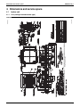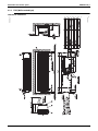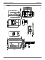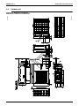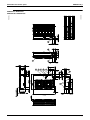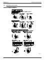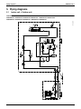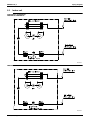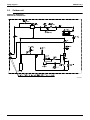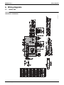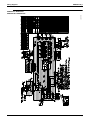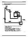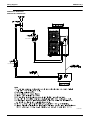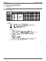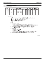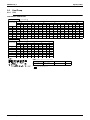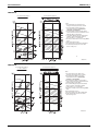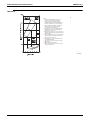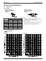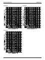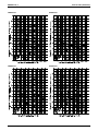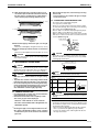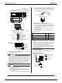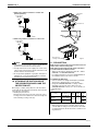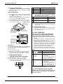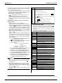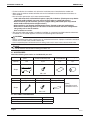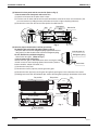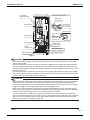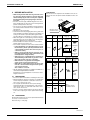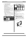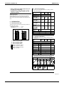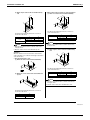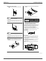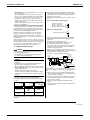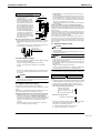
1
EDUS281120_a Cooling Only 60Hz Heat Pump 60Hz RZR-P, RZQ-P(9) series AMERICAS EDUS281120_a SkyAir Engineering Data 1. External appearance ...................................................................................3 1.1 Indoor unit .................................................................................................... 3 1.2 Outdoor unit.................................................................................................. 4 2. Model name, power supply and nomenclature ...........................................5 2.1 Model name and power supply .................................................................... 5 2.2 Nomenclature ............................................................................................... 6 3. Specifications ..............................................................................................7 3.1 Cooling Only................................................................................................. 7 3.2 Heat Pump ................................................................................................. 14 4. Dimensions and service space .................................................................21 4.1 4.2 4.3 4.4 4.5 Indoor unit .................................................................................................. 21 Wired remote controller (Optional) ............................................................. 29 Wireless remote controller (Optional)......................................................... 31 Outdoor unit................................................................................................ 34 Installation service space ........................................................................... 36 5. Piping diagrams ........................................................................................41 5.1 Indoor unit + Outdoor unit .......................................................................... 41 5.2 Indoor unit .................................................................................................. 42 5.3 Outdoor unit................................................................................................ 43 6. Wiring diagrams ........................................................................................44 6.1 Indoor unit .................................................................................................. 44 6.2 Outdoor unit................................................................................................ 48 6.3 External connection diagram...................................................................... 50 7. Electrical characteristics............................................................................52 7.1 Indoor unit .................................................................................................. 52 7.2 Outdoor unit................................................................................................ 56 8. Safety devices list .....................................................................................58 8.1 8.2 8.3 8.4 FCQ............................................................................................................ 58 FHQ............................................................................................................ 59 FAQ ............................................................................................................ 60 FBQ ............................................................................................................ 61 9. Capacity tables..........................................................................................62 9.1 Cooling Only............................................................................................... 62 9.2 Heat Pump ................................................................................................. 72 9.3 Capacity correction ratio............................................................................. 89 10.Fan Performances.....................................................................................92 11.Airflow Auto Adjustment Characteristics ...................................................95 12.Sound Levels (Reference) ........................................................................98 Table of contents 1 EDUS281120_a 12.1 Indoor unit .................................................................................................. 98 12.2 Outdoor unit.............................................................................................. 102 13.Operation limits .......................................................................................104 14.Accessories.............................................................................................106 14.1 Indoor unit ................................................................................................ 106 14.2 Outdoor unit.............................................................................................. 108 15.Center of gravity......................................................................................109 15.1 Indoor unit ................................................................................................ 109 15.2 Outdoor unit.............................................................................................. 111 16.Installation of indoor unit .........................................................................113 16.1 FCQ18PAVJU / FCQ24PAVJU / FCQ30PAVJU / FCQ36PAVJU / FCQ42PAVJU .......................................................................................... 113 16.2 FHQ18PVJU / FHQ24PVJU / FHQ30PVJU ............................................. 138 16.3 FHQ36MVJU / FHQ42MVJU.................................................................... 152 16.4 FAQ18PVJU / FAQ24PVJU ..................................................................... 166 16.5 FBQ18PVJU / FBQ24PVJU / FBQ30PVJU / FBQ36PVJU / FBQ42PVJU............................................................................................. 187 17.Installation of outdoor unit .......................................................................203 17.1 RZR18PVJU / RZR24PVJU / RZR30PVJU / RZQ18PVJU9 / RZQ24PVJU9 / RZQ30PVJU................................................................... 203 17.2 RZR36PVJU / RZR42PVJU / RZQ36PVJU9 / RZQ42PVJU9.................. 221 2 Table of contents EDUS281120_a External appearance 1. External appearance 1.1 Indoor unit Ceiling mounted cassette type (Round flow) FCQ18PAVJU / FCQ24PAVJU / FCQ30PAVJU FCQ36PAVJU / FCQ42PAVJU Ceiling suspended type FHQ18PVJU / FHQ24PVJU / FHQ30PVJU FHQ36MVJU / FHQ42MVJU Wall mounted type FAQ18PVJU / FAQ24PVJU Ceiling mounted duct type FBQ18PVJU / FBQ24PVJU / FBQ30PVJU FBQ36PVJU / FBQ42PVJU RZR-P, RZQ-P(9) 3 External appearance 1.2 EDUS281120_a Outdoor unit RZR18PVJU / RZR24PVJU / RZR30PVJU RZQ18PVJU9 / RZQ24PVJU9 / RZQ30PVJU RZR36PVJU / RZR42PVJU RZQ36PVJU9 / RZQ42PVJU9 4 RZR-P, RZQ-P(9) EDUS281120_a Model name, power supply and nomenclature 2. Model name, power supply and nomenclature 2.1 Model name and power supply 2.1.1 Cooling Only Indoor unit Ceiling mounted cassette type (Round flow) Ceiling suspended type Wall mounted type Ceiling mounted duct type Outdoor unit FCQ18PAVJU* RZR18PVJU FCQ24PAVJU* RZR24PVJU FCQ30PAVJU* RZR30PVJU FCQ36PAVJU* RZR36PVJU FCQ42PAVJU* RZR42PVJU FHQ18PVJU RZR18PVJU FHQ24PVJU RZR24PVJU FHQ30PVJU RZR30PVJU FHQ36MVJU RZR36PVJU FHQ42MVJU RZR42PVJU FAQ18PVJU RZR18PVJU FAQ24PVJU RZR24PVJU FBQ18PVJU* RZR18PVJU FBQ24PVJU* RZR24PVJU FBQ30PVJU* RZR30PVJU FBQ36PVJU* RZR36PVJU FBQ42PVJU* RZR42PVJU Power supply intake Indoor unit: 1 phase, 208/230V, 60Hz Outdoor unit: 1 phase, 208/230V, 60Hz Note: 1. * : New model or changed model 2.1.2 Heat Pump Indoor unit Ceiling mounted cassette type (Round flow) Ceiling suspended type Wall mounted type Ceiling mounted duct type Outdoor unit FCQ18PAVJU* RZQ18PVJU9 FCQ24PAVJU* RZQ24PVJU9 FCQ30PAVJU* RZQ30PVJU FCQ36PAVJU* RZQ36PVJU9 FCQ42PAVJU* RZQ42PVJU9 FHQ18PVJU RZQ18PVJU9 FHQ24PVJU RZQ24PVJU9 FHQ30PVJU RZQ30PVJU FHQ36MVJU RZQ36PVJU9 FHQ42MVJU RZQ42PVJU9 FAQ18PVJU RZQ18PVJU9 FAQ24PVJU RZQ24PVJU9 FBQ18PVJU* RZQ18PVJU9 FBQ24PVJU* RZQ24PVJU9 FBQ30PVJU* RZQ30PVJU FBQ36PVJU* RZQ36PVJU9 FBQ42PVJU* RZQ42PVJU9 Power supply intake Indoor unit: 1 phase, 208/230V, 60Hz Outdoor unit: 1 phase, 208/230V, 60Hz Note: 1. * : New model or changed model RZR-P, RZQ-P(9) 5 Model name, power supply and nomenclature 2.2 EDUS281120_a Nomenclature Indoor unit F C Q 18 PA VJ U Standard compatibility symbol U: United States of America Power supply symbol VJ: 1 phase, 208/230 V, 60 Hz Indicates major design category Capacity indication in cooling 18: 18,000 Btu/h 24: 24,000 Btu/h 30: 30,000 Btu/h 36: 36,000 Btu/h 42: 42,000 Btu/h Refrigerant and Type Q: R410A, Heat pump or Cooling only Shape C: Ceiling mounted cassette (Round flow) H: Ceiling suspended A: Wall mounted B: Ceiling mounted duct type Unit category F: Air cooled split indoor unit Outdoor unit (Cooling Only) R Z R 18 P VJ U Standard compatibility symbol U: United States of America Power supply symbol VJ: 1 phase, 208/230 V, 60 Hz Indicates major design category Capacity indication in cooling 18: 18,000 Btu/h 24: 24,000 Btu/h 30: 30,000 Btu/h 36: 36,000 Btu/h 42: 42,000 Btu/h Refrigerant and Type R: R410A, Cooling Only Inverter/Non inverter Z: Inverter Unit category R: Air cooled split outdoor unit Outdoor unit (Heat Pump) R Z Q 18 P VJ U 9 Management suffix Indicates slight design change Standard compatibility symbol U: United States of America Power supply symbol VJ: 1 phase, 208/230 V, 60 Hz Indicates major design category Capacity indication in cooling 18: 18,000 Btu/h 24: 24,000 Btu/h 30: 30,000 Btu/h 36: 36,000 Btu/h 42: 42,000 Btu/h Refrigerant and Type Q: R410A, Heat Pump Inverter/Non inverter Z: Inverter Unit category R: Air cooled split outdoor unit 6 RZR-P, RZQ-P(9) EDUS281120_a Specifications 3. Specifications 3.1 Cooling Only, 3.1.1 FCQ / Ceiling mounted cassette type (Round flow) Model Indoor unit Outdoor unit Power supply Cooling capacity 1, 2 Btu/h SEER (Rated) EER (Rated) Btu/h-W Indoor unit Color Dimensions H×W×D in (mm) Type Coil Rows×Stages×FPI Face area ft² (m²) Model Fan Type Motor output Airflow rate (HH/H/L) Piping connections 30,000 16.8 15.8 13.9 12.0 10.2 FCQ18PAVJU FCQ24PAVJU FCQ30PAVJU Galvanized steel plate Galvanized steel plate Galvanized steel plate 9–11/16 × 33–1/16 × 33–1/16 (246 x 840 x 840) 9–11/16 × 33–1/16 × 33–1/16 (246 x 840 x 840) 9–11/16 × 33–1/16 × 33–1/16 (246 x 840 x 840) Cross fin coil Cross fin coil Cross fin coil 2 × 6 × 21 2 × 10 × 21 2 × 10 × 21 2.87 (0.9) 4.80 (1.5) 4.80 (1.5) QTS48C15M QTS48C15M QTS48C15M Turbo fan 56 cfm (m3/min) 560/470/390 (16/13/11) 780/620/470 (22/13/11) 830/670/530 (24/13/11) — — — Lbs (kg) 43 (19.5) 48.5 (22) 48.5 (22) in (mm) 1/4 (6.4) (Flare connection) 3/8 (9.5) (Flare connection) 3/8 (9.5) (Flare connection) 1/2 (12.7) (Flare connection) 5/8 (15.8)(Flare connection) 5/8 (15.8) (Flare connection) Drain in (mm) VP25 (External dia. 1–1/4 (31.8), Internal dia. 1 (25.4)) VP25 (External dia. 1–1/4 (31.8), Internal dia. 1 (25.4)) VP25 (External dia. 1–1/4 (31.8), Internal dia. 1 (25.4)) BRC1E71 BRC1E71 BRC1E71 — — — BYCP125K–W1 BYCP125K–W1 BYCP125K–W1 Wired Wireless Color Dimensions H×W×D in (mm) Air filter Lbs (kg) H×W×D in (mm) Rows×Stages×FPI ft² (m²) Model Type Motor output kW Model Type Motor output Airflow rate Mass (Weight) Fresh white Fresh white Fresh white 2 × 37–3/8 × 37–3/8 (51 x 949 x 949) 2 × 37–3/8 × 37–3/8 (51 x 949 x 949) 2 × 37–3/8 × 37–3/8 (51 x 949 x 949) Resin net (with mold resistant) Resin net (with mold resistant) Resin net (with mold resistant) 12.2 (5.5) 12.2 (5.5) 12.2 (5.5) RZR18PVJU RZR24PVJU RZR30PVJU Ivory Ivory Ivory 30–5/16 × 35–7/16 × 12–5/8 (770 x 900 x 321) 30–5/16 × 35–7/16 × 12–5/8 (770 x 900 x 321) 30–5/16 × 35–7/16 × 12–5/8 (770 x 900 x 321) Cross fin coil Cross fin coil Cross fin coil 2 × 34 × 18 2 × 34 × 18 2 × 34 × 18 7.1 (2.2) 7.1 (2.2) 7.1 (2.2) 2YC63HXD#ED 2YC63HXD#ED 2YC63HXD#ED Hermetically sealed swing type Hermetically sealed swing type Hermetically sealed swing type 1.7 1.7 1.7 P47N11F P47N11F P47N11F Propeller fan Propeller fan Propeller fan W 70 70 70 cfm (m3/min) 1,835 (52) 1,835 (52) 1,835 (52) Lbs (kg) 150 (68) 150 (68) 150 (68) in (mm) 3/8 (9.5) (Flare connection) 3/8 (9.5) (Flare connection) 3/8 (9.5) (Flare connection) Gas in (mm) 5/8 15.8)(Flare connection) 5/8 (15.8) (Flare connection) 5/8 (15.8) (Flare connection) Drain in (mm) 1 (25.4) (Hole) 1 (25.4) (Hole) 1 (25.4) (Hole) Liquid High pressure switch. Outdoor fan driver overload protector. Inverter overload protector. Fusible plugs. Fuse. Safety devices Capacity step % Refrigerant control Refrigerant 24,000 17.2 in (mm) Face area Ref. piping 18,000 56 Type Piping connections 1 phase, 208/230V, 60Hz Turbo fan Color Fan 1 phase, 208/230V, 60Hz 56 Outdoor unit Comp. RZR30PVJU 1 phase, 208/230V, 60Hz Liquid Weight Coil FCQ30PAVJU Turbo fan Model Dimensions RZR24PVJU Gas Remote controller (option) Decoration panels (option) FCQ24PAVJU RZR18PVJU W Air filter Mass (Weight) FCQ18PAVJU High pressure switch. Outdoor fan High pressure switch. Outdoor fan driver overload protector. Inverter driver overload protector. Inverter overload protector. Fusible plugs. overload protector. Fusible plugs. Fuse. Fuse. 35-100 30-100 25-100 Electronic expansion valve Electronic expansion valve Electronic expansion valve Standard length ft (m) 25 (7.5) 25 (7.5) 25 (7.5) Max. length ft (m) 164 (50) 164 (50) 164 (50) Max. height difference ft (m) Model Charge (factory charge) Ref. oil Drawing Number Lbs (kg) Model Charge L (oz) 98 (30) 98 (30) 98 (30) R-410A R-410A R-410A 5.1 (2.3) 5.1 (2.3) 5.1 (2.3) Refer to the name plate of compressor. Refer to the name plate of compressor. Refer to the name plate of compressor. 0.75 (25.4) 0.75 (25.4) 0.75 (25.4) C: 4D074132 C: 4D074132 C: 4D074132 1. Indoor temp. : 80°FDB, 67°FWB (27°CDB)/(19.4°CWB) / outdoor temp. : 95°FDB (35°CDB) / Equivalent piping length : 25 ft (7.5 m), level difference : 0. 2. Capacities are net, including a deduction for cooling for indoor fan motor heat. RZR-P, RZQ-P(9) 7 Specifications EDUS281120_a Ceiling mounted cassette type (Round flow), continued Model Indoor unit FCQ36PAVJU Outdoor unit Power supply Cooling capacity 1, 2 Btu/h SEER (Rated) EER (Rated) Btu/h-W Indoor unit Color Dimensions H×W×D in (mm) Type Coil Rows×Stages×FPI Face area ft² (m²) Model Fan Type Motor output Airflow rate (HH/H/L) Piping connections 11–5/16 × 33–1/16 × 33–1/16 (287 x 840 x 840) 11–5/16 × 33–1/16 × 33–1/16 (287 x 840 x 840) Cross fin coil Cross fin coil 2 × 12 × 21 2 × 12 × 21 5.76 (1.8) 5.76 (1.8) QTS48C15M QTS48C15M Turbo fan Turbo fan 120 — — Lbs (kg) 55 (25) 55 (25) in (mm) 3/8 (9.5) (Flare connection) 3/8 (9.5) (Flare connection) 5/8 (15.8) (Flare connection) 5/8 (15.8) (Flare connection) Drain in (mm) VP25 (External dia. 1–1/4 (31.8), Internal dia. 1 (25.4)) VP25 (External dia. 1–1/4 (31.8), Internal dia. 1 (25.4)) BRC1E71 BRC1E71 Wired Wireless Color Dimensions H×W×D in (mm) Air filter Lbs (kg) H×W×D in (mm) Rows×Stages×FPI ft² (m²) Model Type Motor output kW Model Type Motor output Airflow rate Mass (Weight) — — BYCP125K–W1 BYCP125K–W1 Fresh white Fresh white 2 × 37–3/8 × 37–3/8 (51 x 949 x 949) 2 × 37–3/8 × 37–3/8 (51 x 949 x 949) Resin net (with mold resistant) Resin net (with mold resistant) 12.2 (5.5) 12.2 (5.5) RZR36PVJU RZR42PVJU Ivory white (5Y7.5/1) Ivory white (5Y7.5/1) 52–15/16 × 35–7/16 × 12–5/8 (1345 x 900 x 321) 52–15/16 × 35–7/16 × 12–5/8 (1345 x 900 x 321) Cross fin coil Cross fin coil 2 × 60 × 13 2 × 60 × 13 12.2 (3.7) 12.2 (3.7) JT100G-VDLW@T JT100G-VDLW@T Hermetically sealed scroll type Hermetically sealed scroll type 2.5 3.0 KFD–325–70–8C2 KFD–325–70–8C2 Propeller fan Propeller fan W 70 × 2 70 × 2 cfm (m3/min) 3,740 (106) 3,740 (106) Lbs (kg) 283 (128) 283 (128) in (mm) 3/8 (9.5) (Flare connection) 3/8 (9.5) (Flare connection) Gas in (mm) 5/8 (15.8) (Flare connection) 5/8 (15.8) (Flare connection) Drain in (mm) 1 (25.4) (Hole) 1 (25.4) (Hole) High pressure switch. Outdoor fan driver overload protector. Inverter overload protector. Fusible plugs. Fuse. High pressure switch. Outdoor fan driver overload protector. Inverter overload protector. Fusible plugs. Fuse. Liquid Safety devices Capacity step % Refrigerant control Refrigerant FCQ42PAVJU Galvanized steel plate in (mm) Face area Ref. piping FCQ36PAVJU Galvanized steel plate 1220/970/790 (35/28/22) Type Piping connections 10.2 1180/910/700 (33/26/20) Color Fan 16.0 11.2 cfm (m3/min) Outdoor unit Comp. 42,000 17.5 Liquid Weight Coil 36,000 120 Model Dimensions 1 phase, 208/230V, 60Hz Gas Remote controller (option) Decoration panels (option) RZR42PVJU 1 phase, 208/230V, 60Hz W Air filter Mass (Weight) FCQ42PAVJU RZR36PVJU 25-100 25-100 Electronic expansion valve Electronic expansion valve Standard length ft (m) 25 (7.5) 25 (7.5) Max. length ft (m) 230 (70) 230 (70) Max. height difference ft (m) 164 (50) 164 (50) R-410A R-410A Model Charge (factory charge) Ref. oil Drawing Number Lbs (kg) Model Charge L (oz) 8.8 (4) 8.8 (4) Refer to the name plate of compressor. Refer to the name plate of compressor. 1.5 (50.7) 1.5 (50.7) C: 4D074133 C: 4D074133 Notes: 1. Indoor temp. : 80°FDB, 67°FWB (27°CDB /19.4°CWB) / outdoor temp. : 95°FDB (35°CDB) / Equivalent piping length : 25ft (7.5 m), level difference : 0. 2. Capacities are net, including a deduction for cooling for indoor fan motor heat. 8 RZR-P, RZQ-P(9) EDUS281120_a 3.1.2 Specifications FHQ Ceiling suspended type Model Indoor unit FHQ18PVJU FHQ24PVJU Outdoor unit RZR18PVJU RZR24PVJU RZR30PVJU 1 phase, 208/230V, 60Hz 1 phase, 208/230V, 60Hz 1 phase, 208/230V, 60Hz 18,000 24,000 30,000 18.0 18.1 17.2 14.0 12.6 10.5 FHQ18PVJU FHQ24PVJU FHQ30PVJU Power supply Cooling capacity 1, 2 Btu/h SEER (Rated) EER (Rated) Btu/h-W Indoor unit Color Dimensions H×W×D in (mm) Type Coil Rows×Stages×FPI Face area Fan ft² (m²) — Sirocco fan Sirocco fan Motor output W 130 130 130 cfm (m3/min) 790/670 (22/19) 790/670 (22/19) 790/670 (22/19) Resin net (With mold resistant) Resin net (With mold resistant) Resin net (With mold resistant) Lbs (kg) 90 (41) 90 (41) 90 (41) Liquid in (mm) 3/8 (9.5) (Flare Connection) 3/8 (9.5) (Flare connection) 3/8 (9.5) (Flare connection) Gas in (mm) 5/8 (15.8) (Flare connection) 5/8 (15.8) (Flare connection) 5/8 (15.8) (Flare connection) in (mm) VP20 (External dia. 1 (25.4), Internal dia. 3/4 (19.1)) VP20 (External dia. 1 (25.4), Internal dia. 3/4 (19.1)) VP20 (External dia. 1 (25.4), Internal dia. 3/4 (19.1)) Wired BRC1E71 BRC1E71 BRC1E71 Wireless BRC7E83 BRC7E83 BRC7E83 RZR18PVJU RZR24PVJU RZR30PVJU H×W×D in (mm) Type Rows×Stages×FPI Face area ft² (m²) Model Type Motor output kW Model Type Motor output Airflow rate Mass (Weight) Ivory Ivory Ivory 30–5/16 × 35–7/16 × 12–5/8 (770 x 900 x 321) 30–5/16 × 35–7/16 × 12–5/8 (770 x 900 x 321) 30–5/16 × 35–7/16 × 12–5/8 (770 x 900 x 321) Cross fin coil Cross fin coil Cross fin coil 2 × 34 × 18 2 × 34 × 18 2 × 34 × 18 7.1 (2.2) 7.1 (2.2) 7.1 (2.2) 2YC63HXD#ED 2YC63HXD#ED 2YC63HXD#ED Hermetically sealed swing type Hermetically sealed swing type Hermetically sealed swing type 1.7 1.7 1.7 P47N11F P47N11F P47N11F Propeller fan Propeller fan Propeller fan W 70 70 70 cfm (m3/min) 1,835 (52) 1,835 (52) 1,835 (52) Lbs (kg) 150 (68) 150 (68) 150 (68) in (mm) 3/8 (9.5) (Flare connection) 3/8 (9.5) (Flare connection) 3/8 (9.5) (Flare connection) Gas in (mm) 5/8 (15.8) (Flare connection) 5/8 (15.8) (Flare connection) 5/8 (15.8) (Flare connection) Drain in (mm) 1 (25.4) (Hole) 1 (25.4) (Hole) 1 (25.4) (Hole) High pressure switch. Outdoor fan driver overload protector. Thermal protector for indoor fan motor. Inverter overload protector. Fusible plugs. Fuse. High pressure switch. Outdoor fan driver overload protector. Thermal protector for indoor fan motor. Inverter overload protector. Fusible plugs. Fuse. Liquid High pressure switch. Outdoor fan driver overload protector. Thermal protector for indoor fan motor. Inverter overload protector. Fusible plugs. Fuse. Safety devices Capacity step % Refrigerant control Refrigerant 3.66 + 2.95 (1.1 + 0.9) Sirocco fan Color Ref. piping Cross fin coil 2 × 12 × 15 + 2 × 10 × 15 Type Outdoor unit Piping connections Cross fin coil 2 × 12 × 15 + 2 × 10 × 15 — Remote controller (option) Fan Cross fin coil 2 × 12 × 15 + 2 × 10 × 15 3.66 + 2.95 (1.1 + 0.9) Drain Comp. White (10Y9/0.5) 7–11/16 × 62–5/8 × 26–3/4 (195 x 1591 x 680) — Mass (Weight) Coil White (10Y9/0.5) 7–11/16 × 62–5/8 × 26–3/4 (195 x 1591 x 680) 3.66 + 2.95 (1.1 + 0.9) Air filter Dimensions White (10Y9/0.5) 7–11/16 × 62–5/8 × 26–3/4 (195 x 1591 x 680) Model Airflow rate (H/L) Piping connections FHQ30PVJU 35-100 30-100 25-100 Electronic expansion valve Electronic expansion valve Electronic expansion valve Standard length ft (m) 25 (7.5) 25 (7.5) 25 (7.5) Max. length ft (m) 164 (50) 164 (50) 164 (50) Max. height difference ft (m) Model Charge (factory charge) Ref. oil Drawing Number Lbs (kg) 98 (30) 98 (30) 98 (30) R-410A R-410A R-410A 5.1 (2.3) 5.1 (2.3) Refer to the name plate of compressor. Refer to the name plate of compressor. C: 4D071679 5.1 (2.3) Refer to the name plate of compressor. C: 4D071679 C: 4D071679 Notes: 1. Indoor temp. : 80°FDB, 67°FWB (27°CDB /19.4°CWB) / outdoor temp. : 95°FDB (35°CDB) / Equivalent piping length : 25ft (7.5 m), level difference : 0. 2. Capacities are net, including a deduction for cooling for indoor fan motor heat. RZR-P, RZQ-P(9) 9 Specifications EDUS281120_a Ceiling suspended type, continued Model Indoor unit FHQ36MVJU Outdoor unit RZR36PVJU RZR42PVJU 1 phase, 208/230V, 60Hz 1 phase, 208/230V, 60Hz 36,000 40,500 14.0 13.8 Power supply Cooling capacity 1, 2 Btu/h SEER (Rated) EER (Rated) Btu/h-W Indoor unit Color Dimensions H×W×D in (mm) Type Coil Rows×Stages×FPI Face area Fan ft² (m²) Motor output 3.66 + 2.95 (1.1 + 0.9) 130 130 830/670 (24/19) 850/700 (24/20) Resin net (With mold resistant) Resin net (With mold resistant) Lbs (kg) 90 (41) 90 (41) in (mm) 3/8 (9.5) (Flare connection) 3/8 (9.5) (Flare connection) Gas in (mm) 5/8 (15.8) (Flare connection) 5/8 (15.8) (Flare connection) Drain in (mm) VP20 (External dia. 1 (25.4), Internal dia. 3/4 (19.1)) VP20 (External dia. 1 (25.4), Internal dia. 3/4 (19.1)) Wired BRC1E71 BRC1E71 Wireless BRC7E83 BRC7E83 H×W×D in (mm) Rows×Stages×FPI Face area ft² (m²) Model Type Motor output kW Model Type Motor output Airflow rate Mass (Weight) RZR36PVJU RZR42PVJU Ivory white (5Y7.5/1) Ivory white (5Y7.5/1) 52–15/16 × 35–7/16 × 12–5/8 (1345 x 900 x 321) 52–15/16 × 35–7/16 × 12–5/8 (1345 x 900 x 321) Cross fin coil Cross fin coil 2 × 60 × 13 2 × 60 × 13 12.2 (3.7) 12.2 (3.7) JT100G-VDLW@T JT100G-VDLW@T Hermetically sealed scroll type Hermetically sealed scroll type 2.5 3.0 KFD–325–70–8C2 KFD–325–70–8C2 Propeller Fan Propeller Fan W 70×2 70×2 cfm (m3/min) 3,740 (106) 3,740 (106) Lbs (kg) 283 (128) 283 (7.5 m) in (mm) 3/8 (9.5) (Flare connection) 3/8 (9.5) (Flare connection) Gas in (mm) 5/8 (15.8) (Flare connection) 5/8 (15.8) (Flare connection) Drain in (mm) 1 (25.4) (Hole) 1 (25.4) (Hole) High pressure switch. Outdoor fan driver overload protector. Thermal protector for indoor fan motor. Inverter overload protector. Fusible plugs. Fuse. High pressure switch. Outdoor fan driver overload protector. Thermal protector for indoor fan motor. Inverter overload protector. Fusible plugs. Fuse. Liquid Safety devices Capacity step % Refrigerant control Ref. oil 3.66 + 2.95 (1.1 + 0.9) W Type Refrigerant Cross fin coil 2 × 12 × 15 + 2 × 10 × 15 cfm (m3/min) Color Ref. piping Cross fin coil 2 × 12 × 15 + 2 × 10 × 15 — Outdoor unit Piping connections White (10Y9/0.5) 7–11/16 × 62–5/8 × 26–3/4 (195 x 1591 x 680) Sirocco fan Remote controller (option) Fan White (10Y9/0.5) 7–11/16 × 62–5/8 × 26–3/4 (195 x 1591 x 680) Sirocco fan Liquid Comp. FHQ42MVJU Type Mass (Weight) Coil 9.5 FHQ36MVJU — Air filter Dimensions 10.2 Model Airflow rate (H/L) Piping connections FHQ42MVJU 25-100 25-100 Electronic expansion valve Electronic expansion valve Standard length ft (m) 25 (7.5) 25 (7.5) Max. length ft (m) 230 (70) 230 (70) Max. height difference ft (m) 164 (50) 164 (50) R-410A R-410A Model Charge (factory charge) Lbs (kg) Model Charge Drawing Number L (oz) 8.8 (4) 8.8 (4) Refer to the name plate of compressor. Refer to the name plate of compressor. 1.5 (51) 1.5 (51) C: 4D071676 C: 4D071676 Notes: 1. Indoor temp. : 80°FDB, 67°FWB (27°CDB /19.4°CWB) / outdoor temp. : 95°FDB (35°CDB) / Equivalent piping length : 25 ft (7.5 m), level difference : 0. 2. Capacities are net, including a deduction for cooling for indoor fan motor heat. 10 RZR-P, RZQ-P(9) EDUS281120_a 3.1.3 Specifications FAQ Wall mounted type Model Indoor unit FAQ18PVJU Outdoor unit RZR18PVJU RZR24PVJU 1 phase, 208/230V, 60Hz 1 phase, 208/230V, 60Hz 18,000 24,000 Power supply Cooling capacity 1, 2 Btu/h SEER (Rated) EER (Rated) Btu/h-W Indoor unit Color Dimensions H×W×D in (mm) Type Coil Rows×Stages×FPI Face area ft² (m²) Model Fan Type Motor output Airflow rate (H/L) Liquid Piping connections Cross fin coil 2 × 14 × 18 2 × 14 × 18 2.29 (0.7) 2.29 (0.7) QCL9686M QCL9686M Cross flow fan Cross flow fan 43 Resin net (Washable) Resin net (Washable) Lbs (kg) 31 (14) 31 (14) in (mm) 3/8 (9.5) (Flare connection) 3/8 (9.5)(Flare connection) in (mm) 5/8 (15.8) (Flare connection) 5/8 (15.8)(Flare connection) in (mm) VP13 (External dia. 11/16 (17.5), Internal dia. 1/2 (12.7)) VP13 (External dia. 11/16 (17.5), Internal dia. 1/2 (12.7)) Wired BRC1E71 BRC1E71 Wireless BRC7E818 BRC7E818 RZR18PVJU RZR24PVJU H×W×D in (mm) Rows×Stages×FPI ft² (m²) Type Motor output kW Model Type Motor output Airflow rate Mass (Weight) Ivory Ivory 30–5/16 × 35–7/16 × 12–5/8 (770 x 900 x 321) 30–5/16 × 35–7/16 × 12–5/8 (770 x 900 x 321) Cross fin coil Cross fin coil 2 × 34 × 18 2 × 34 × 18 7.1 (2.2) 7.1 (2.2) 2YC63HXD#ED 2YC63HXD#ED Hermetically sealed swing type Hermetically sealed swing type 1.7 1.7 P47N11F P47N11F Propeller fan Propeller fan W 70 70 cfm (m3/min) 1,835 (52) 1,835 (52) Lbs (kg) 150 (68) 150 (68) in (mm) 3/8 (9.5) (Flare connection) 3/8 (9.5) (Flare connection) Gas in (mm) 5/8 (15.8) (Flare connection) 5/8 (15.8) (Flare connection) Drain in (mm) 1 (25.4) (Hole) 1 (25.4) (Hole) High pressure switch. Outdoor fan driver overload protector. Thermal protector for indoor fan motor. Inverter overload protector. Fusible plugs. Fuse. High pressure switch. Outdoor fan driver overload protector. Thermal protector for indoor fan motor. Inverter overload protector. Fusible plugs. Fuse. Liquid Safety devices Capacity step % Refrigerant control Refrigerant 11–3/8 × 41–3/8 × 9 (289 x 1051 x 229) Cross fin coil 635/470 (18/13) Model Ref. piping 11–3/8 × 41–3/8 × 9 (289 x 1051 x 229) Gas Face area Piping connections FAQ24PVJU White (3.0Y8.5/0.5) 500/400 (14/11) Type Fan FAQ18PVJU White (3.0Y8.5/0.5) cfm (m3/min) Outdoor unit Comp. 10.2 43 Color Coil 17.6 12.7 Drain Remote controller (option) Dimensions 18.6 W Air filter Mass (Weight) FAQ24PVJU 35-100 30-100 Electronic expansion valve Electronic expansion valve Standard length ft (m) 25 (7.5) 25 (7.5) Max. length ft (m) 164 (50) 164 (50) Max. height difference ft (m) Model Charge (factory charge) Ref. oil Drawing Number Lbs (kg) 98 (30) 98 (30) R-410A R-410A 5.1 (2.3) 5.1 (2.3) Refer to the name plate of compressor. Refer to the name plate of compressor. C: 4D071677 C: 4D071677 Notes: 1. Indoor temp. : 80°FDB, 67°FWB (27°CDB /19.4°CWB) / outdoor temp. : 95°FDB (35°CDB) / Equivalent piping length : 25 ft (7.5 m), level difference : 0. 2. Capacities are net, including a deduction for cooling for indoor fan motor heat. RZR-P, RZQ-P(9) 11 Specifications 3.1.4 EDUS281120_a FBQ Model Indoor unit FBQ18PVJU FBQ24PVJU Outdoor unit RZR18PVJU RZR24PVJU RZR30PVJU 1 phase, 208/230V, 60Hz 1 phase, 208/230V, 60Hz 1 phase, 208/230V, 60Hz 18,000 24,000 30,000 17.5 16.5 16.0 14.1 12.0 10.5 FBQ18PVJU FBQ24PVJU FBQ30PVJU Power supply Cooling capacity 1, 2 Btu/h SEER (Rated) EER (Rated) Btu/h-W Indoor unit Color Dimensions Galvanized steel plate Galvanized steel plate Galvanized steel plate 11–13/16 × 39–3/8 × 27–9/16 (300 x 1000 x 700) 11–13/16 × 39–3/8 × 27–9/16 (300 x 1000 x 700) 11–13/16 × 39–3/8 × 27–9/16 (300 x 1000 x 700) Cross fin coil Cross fin coil Cross fin coil 3 × 16 × 15 3 × 16 × 15 3 × 16 × 15 2.68 (0.8) 2.68 (0.8) 2.68 (0.8) Model — — — Type Sirocco fan Sirocco fan Sirocco fan H×W×D in (mm) Type Coil Rows×Stages×FPI Face area Fan ft² (m²) Motor output Airflow rate (HH/H/L) External static pressure W 350 350 350 cfm (m3/min) 635/582/529 (18 / 16.5 /15) 688/618/565 (19.5 / 17.5 / 16) 882/794/706 (25 / 22.5 / 20) “Wg Standard 0.40 (0.80–0.20 3) Standard 0.40 (0.80–0.20 3) Standard 0.40 (0.80–0.20 3) Note 4 Note 4 Note 4 80 (36) 80 (36) 80 (36) Air filter Mass (Weight) Piping connections Lbs (kg) Liquid in (mm) 1/4 (6.4) (Flare connection) 3/8 (9.5) (Flare connection) 3/8 (9.5) (Flare connection) Gas in (mm) 1/2 (12.7) (Flare connection) 5/8 (15.8) (Flare connection) 5/8 (15.8) (Flare connection) Drain in (mm) VP25 (External dia. 1-1/4 (31.8), internal dia.1 (25.4)) VP25 (External dia. 1-1/4 (31.8), internal dia.1 (25.4)) VP25 (External dia. 1-1/4 (31.8), internal dia.1 (25.4)) Remote controller (option) Wired BRC1E71 BRC1E71 BRC1E71 Wireless BRC4C82 BRC4C82 BRC4C82 RZR18PVJU RZR24PVJU RZR30PVJU Ivory Ivory Ivory 30–5/16 × 35–7/16 × 12–5/8 (770 x 900 x 321) 30–5/16 × 35–7/16 × 12–5/8 (770 x 900 x 321) 30–5/16 × 35–7/16 × 12–5/8 (770 x 900 x 321) Cross fin coil Cross fin coil Cross fin coil 2 × 34 × 18 2 × 34 × 18 2 × 34 × 18 7.1 (2.2) 7.1 (2.2) 7.1 (2.2) 2YC63HXD#ED 2YC63HXD#ED 2YC63HXD#ED Hermetically sealed swing type Hermetically sealed swing type Hermetically sealed swing type 1.7 1.7 1.7 P47N11F P47N11F P47N11F Propeller fan Outdoor unit Color Dimensions H×W×D in (mm) Type Coil Rows×Stages×FPI Face area ft² (m²) Model Comp. Type Motor output kW Model Fan Type Motor output Airflow rate Mass (Weight) Propeller fan Propeller fan W 70 70 70 cfm (m3/min) 1,835 (52) 1,835 (52) 1,835 (52) Lbs (kg) 150 (68) 150 (68) 150 (68) in (mm) 3/8 (9.5) (Flare connection) 3/8 (9.5) (Flare connection) 3/8 (9.5) (Flare connection) Gas in (mm) 5/8 (15.8) (Flare connection) 5/8 (15.8) (Flare connection) 5/8 (15.8) (Flare connection) Drain in (mm) 1 (25.4) (Hole) 1 (25.4) (Hole) 1 (25.4) (Hole) High pressure switch. Outdoor fan driver overload protector. Thermal protector for indoor fan motor. Inverter overload protector. Fusible plugs. Fuse. High pressure switch. Outdoor fan driver overload protector. Thermal protector for indoor fan motor. Inverter overload protector. Fusible plugs. Fuse. High pressure switch. Outdoor fan driver overload protector. Thermal protector for indoor fan motor. Inverter overload protector. Fusible plugs. Fuse. Liquid Piping connections Safety devices Capacity step % Refrigerant control Ref. piping Refrigerant Ref. oil FBQ30PVJU 35-100 30-100 25-100 Electronic expansion valve Electronic expansion valve Electronic expansion valve Standard length ft (m) 25 (7.5) 25 (7.5) 25 (7.5) Max. length ft (m) 164 (50) 164 (50) 164 (50) Max. height difference ft (m) Model Charge Lbs (kg) Model Charge Drawing Number L (oz) 98 (30) 98 (30) 98 (30) R-410A R-410A R-410A 5.1 (2.3) 5.1 (2.3) 5.1 (2.3) Refer to the name plate of compressor. Refer to the name plate of compressor. Refer to the name plate of compressor. 0.75 (25.4) 0.75 (25.4) 0.75 (25.4) C: 4D074134 C: 4D074134 C: 4D074134 Notes: 1. 2. 3. 4. 12 Indoor temp. : 80°FDB, 67°FWB (27°CDB /19.4°CWB) / outdoor temp. : 95°FDB (35°CDB) / Equivalent piping length : 25ft (7.5 m), level difference : 0. Capacities are net, including a deduction for cooling for indoor fan motor heat. External static pressure is changeable in 14 stages within the ( ) range by remote controller. An air filter is not a standard accessory, but should be mounted in the duct system of the suction side. Select dust collection efficiency of (gravity method) 50% or more. RZR-P, RZQ-P(9) EDUS281120_a Model Specifications Indoor unit FBQ36PVJU Outdoor unit RZR36PVJU RZR42PVJU 1 phase, 208/230V, 60Hz 1 phase, 208/230V, 60Hz 36,000 42,000 17.5 16.0 Power supply Cooling capacity 1, 2 Btu/h SEER (Rated) EER (Rated) Btu/h-W Indoor unit Color Dimensions H×W×D in (mm) Type Coil Rows×Stages×FPI Face area Fan ft² (m²) Motor output 4.12 (1.3) 350 350 1130/953/812 (32/27/23) 1377/1165/988 (39/33/28) “Wg Standard 0.40 (0.80–0.203) Standard 0.40 (0.80–0.203) Note 4 Note 4 Lbs (kg) 102 (46) 102 (46) in (mm) 3/8 (9.5) (Flare connection) 3/8 (9.5) (Flare connection) Gas in (mm) 5/8 (15.8) (Flare connection) 5/8 (15.8) (Flare connection) Drain in (mm) VP25 (External dia. 1–1/4 (31.8), Internal dia. 1 (25.4)) VP25 (External dia. 1–1/4 (31.8), Internal dia. 1 (25.4)) Wired BRC1E71 BRC1E71 Wireless BRC4C82 BRC4C82 H×W×D in (mm) Type Rows×Stages×FPI Face area ft² (m²) Model Type Motor output kW Model Type Motor output Airflow rate Mass (Weight) RZR36PVJU RZR42PVJU Ivory white (5Y7. 5/1) Ivory white (5Y7. 5/1) 52–15/16 × 35–7/16 × 12–5/8 (1345 x 900 x 321) 52–15/16 × 35–7/16 × 12–5/8 (1345 x 900 x 321) Cross fin coil Cross fin coil 2 × 60 × 13 2 × 60 × 13 12.2 (3.7) 12.2 (3.7) JT100G-VDLW@T JT100G-VDLW@T Hermetically sealed scroll type Hermetically sealed scroll type 2.5 3.0 KFD-325-70-8C2 KFD-325-70-8C2 Propeller fan Propeller fan W 70×2 70×2 cfm (m3/min) 3,740 (106) 3,740 (106) Lbs (kg) 283 (128) 283 (128) in (mm) 3/8 (9.5) (Flare connection) 3/8 (9.5) (Flare connection) Gas in (mm) 5/8 (15.8) (Flare connection) 5/8 (15.8) (Flare connection) Drain in (mm) 1 (25.4) (Hole) 1 (25.4) (Hole) High pressure switch. Outdoor fan driver overload protector. Thermal protector for indoor fan motor. Inverter overload protector. Fusible plugs. Fuse. High pressure switch. Outdoor fan driver overload protector. Thermal protector for indoor fan motor. Inverter overload protector. Fusible plugs. Fuse. Liquid Safety devices Capacity step % Refrigerant control Ref. oil 3 × 16 × 15 4.12 (1.3) W Color Refrigerant Cross fin coil 3 × 16 × 15 cfm (m3/min) Outdoor unit Ref. piping Cross fin coil — Remote controller (option) Piping connections Galvanized steel plate 11–13/16 × 55–1/8 × 27–9/16 (300 x 1400 x 700) Sirocco fan Liquid Fan Galvanized steel plate 11–13/16 × 55–1/8 × 27–9/16 (300 x 1400 x 700) Sirocco fan Mass (Weight) Comp. FBQ42PVJU Type External static pressure Coil 10.2 FBQ36PVJU — Air filter Dimensions 11.2 Model Airflow rate (HH/H/L) Piping connections FBQ42PVJU 25-100 25-100 Electronic expansion valve Electronic expansion valve Standard length ft (m) 25 (7.5) 25 (7.5) Max. length ft (m) 230 (70) 230 (70) Max. height difference ft (m) 164 (50) 164 (50) R-410A R-410A Model Charge Lbs (kg) Model Charge Drawing Number L (oz) 8.8 (4) 8.8 (4) Refer to the name plate of compressor. Refer to the name plate of compressor. 1.5 (50) 1.5 (50) C: 4D074135 C: 4D074135 Notes: 1. 2. 3. 4. Indoor temp. : 80°FDB, 67°FWB (27°CDB)/(19.4°CWB) / outdoor temp. : 95°FDB (35°CDB) / Equivalent piping length : 25 ft (7.5 m), level difference : 0. Capacities are net, including a deduction for cooling for indoor fan motor heat. External static pressure is changeable in 14 stages within the ( ) range by remote controller. An air filter is not a standard accessory, but should be mounted in the duct system of the suction side. Select dust collection efficiency of (gravity method) 50% or more. RZR-P, RZQ-P(9) 13 Specifications EDUS281120_a 3.2 Heat Pump 3.2.1 FCQ / Ceiling mounted cassette type (Round flow) Model Indoor unit FCQ18PAVJU FCQ24PAVJU Outdoor unit RZQ18PVJU9 RZQ24PVJU9 RZQ30PVJU 1 phase, 208/230V, 60Hz 1 phase, 208/230V, 60Hz 1 phase, 208/230V, 60Hz Power supply FCQ30PAVJU Cooling capacity 1, 4 Btu/h 18,000 24,000 30,000 Heating capacity 2, 4 Btu/h 20,000 27,000 34,000 Heating capacity 3, 4 Btu/h 12,000 18,000 22,000 17.2 16.8 15.8 13.9 12.0 10.2 SEER (Rated) EER (Rated) Btu/h-W HSPF (Rated) Indoor unit Color Dimensions H×W×D in (mm) Type Coil Rows×Stages×FPI Face area ft² (m²) Model Fan Type Motor output Airflow rate (HH/H/L) Piping connections 4.80 (1.5) 4.80 (1.5) QTS48C15M QTS48C15M QTS48C15M Turbo fan 56 560/470/390 (16/13/11) 780/620/470 (22/16/13) 830/670/530 (24/19/15) — — — Lbs (kg) 43 (19.5) 48.5 (22) 48.5 (22) in (mm) 1/4 (6.4) (Flare connection) 3/8 (9.5) (Flare connection) 3/8 (9.5) (Flare connection) 1/2 (12.7) (Flare connection) 5/8 (15.8) (Flare connection) 5/8 (15.8) (Flare connection) Drain in (mm) VP25 (External dia. 1–1/4 (31.8), Internal dia. 1 (25.4)) VP25 (External dia. 1–1/4 (31.8), Internal dia. 1 (25.4)) VP25 (External dia. 1–1/4 (31.8), Internal dia. 1 (25.4)) BRC1E71 BRC1E71 BRC1E71 — — — BYCP125K–W1 BYCP125K–W1 BYCP125K–W1 Wired Wireless Color Dimensions H×W×D in (mm) Air filter H×W×D Lbs (kg) in (mm) Rows×Stages×FPI ft² (m²) Type Motor output kW Model Type Motor output Airflow rate Mass (Weight) Fresh white Fresh white Fresh white 2 × 37–3/8 × 37–3/8 (51 x 949 x 949) 2 × 37–3/8 × 37–3/8 (51 x 949 x 949) 2 × 37–3/8 × 37–3/8 (51 x 949 x 949) Resin net (with mold resistant) Resin net (with mold resistant) Resin net (with mold resistant) 12.2 (5.5) 12.2 (5.5) 12.2 (5.5) RZQ18PVJU9 RZQ24PVJU9 RZQ30PVJU Ivory Ivory Ivory 30–5/16 × 35–7/16 × 12–5/8 (770 x 900 x 321) 30–5/16 × 35–7/16 × 12–5/8 (770 x 900 x 321) 30–5/16 × 35–7/16 × 12–5/8 (770 x 900 x 321) Cross fin coil Cross fin coil Cross fin coil 2 × 34 × 18 2 × 34 × 18 2 × 34 × 18 7.1 (2.2) 7.1 (2.2) 7.1 (2.2) 2YC63HXD#ED 2YC63HXD#ED 2YC63HXD#ED Hermetically sealed swing type Hermetically sealed swing type Hermetically sealed swing type 1.7 1.7 1.7 P47N11F P47N11F P47N11F Propeller fan Propeller fan Propeller fan W 70 70 70 cfm (m3/min) 1,835 (52) 1,835 (52) 1,835 (52) Lbs (kg) 150 (68) 150 (68) 150 (68) in (mm) 3/8 (9.5) (Flare connection) 3/8 (9.5) (Flare connection) 3/8 (9.5) (Flare connection) Gas in (mm) 5/8 (15.8) (Flare connection) 5/8 (15.8)(Flare connection) 5/8 (15.8) (Flare connection) Drain in (mm) 1 (25.4) (Hole) 1 (25.4)(Hole) 1 (25.4) (Hole) High pressure switch. Outdoor fan driver overload protector. Inverter overload protector.Fusible plugs. Fuse. High pressure switch. Outdoor fan driver overload protector. Inverter overload protector.Fusible plugs. Fuse. High pressure switch. Outdoor fan driver overload protector. Inverter overload protector.Fusible plugs. Fuse. Liquid Safety devices Capacity step % Refrigerant control Ref. oil 2 × 10 × 21 2.87 (0.9) cfm (m3/min) Model Refrigerant Cross fin coil 2 × 10 × 21 in (mm) Face area Ref. piping Cross fin coil 2 × 6 × 21 56 Type Piping connections Cross fin coil Turbo fan Color Fan Galvanized steel plate 9–11/16 × 33–1/16 × 33–1/16 (246 x 840 x 840) 56 Outdoor unit Comp. Galvanized steel plate 9–11/16 × 33–1/16 × 33–1/16 (246 x 840 x 840) Liquid Weight Coil Galvanized steel plate 9–11/16 × 33–1/16 × 33–1/16 (246 x 840 x 840) Turbo fan Model Dimensions 9.7 FCQ30PAVJU Gas Remote controller (option) Decoration panels (option) 9.7 FCQ24PAVJU W Air filter Mass (Weight) 10.1 FCQ18PAVJU 35-100 30-100 25-100 Electronic expansion valve Electronic expansion valve Electronic expansion valve Standard length ft (m) 25 (7.5) 25 (7.5) 25 (7.5) Max. length ft (m) 164 (50) 164 (50) 164 (50) Max. height difference ft (m) Model Charge (factory charge) Lbs (kg) Model Charge Drawing Number L (oz) 98 (30) 98 (30) 98 (30) R-410A R-410A R-410A 5.1 (2.3) 5.1 (2.3) 5.1 (2.3) Refer to the name plate of compressor. Refer to the name plate of compressor. Refer to the name plate of compressor. 0.75 (25) 0.75 (25) 0.75 (25) C: 4D074128 C: 4D074128 C: 4D074128 1. Indoor temp. : 80°FDB, 67°FWB (27°CDB)/(19.4°CWB) / outdoor temp. : 95°FDB (35°CDB) / Equivalent piping length : 25 ft (7.5 m), level difference : 0. 2. Indoor temp. : 70°FDB (21°CDB) / outdoor temp. : 47°FDB, 43°FWB (8.3°CDB / 6°CWB)/ Equivalent piping length : 25 ft (7.5 m), level difference : 0. 3. Indoor temp. : 70°FDB (21°CDB)/ outdoor temp. : 17°FDB, 15°FWB (-8.3°CDB /-9.4°CWB) / Equivalent piping length : 25 ft (7.5 m), level difference : 0. 14 RZR-P, RZQ-P(9) EDUS281120_a Specifications 4. Capacities are net, including a deduction for cooling (an addition for heating) for indoor fan motor heat. RZR-P, RZQ-P(9) 15 Specifications EDUS281120_a Ceiling mounted cassette type (Round flow), continued Model Indoor unit FCQ36PAVJU Outdoor unit RZQ36PVJU9 RZQ42PVJU9 1 phase, 208/230V, 60Hz 1 phase, 208/230V, 60Hz Power supply FCQ42PAVJU Cooling capacity 1, 4 Btu/h 36,000 42,000 Heating capacity 2, 4 Btu/h 40,000 47,000 Heating capacity 3, 4 Btu/h 21,000 25,000 SEER (Rated) EER (Rated) Btu/h-W HSPF (Rated) Indoor unit Color Dimensions H×W×D in (mm) Type Coil Rows×Stages×FPI Face area ft² (m²) Model Fan Type Motor output Airflow rate (HH/H/L) Piping connections Turbo fan Turbo fan — — Lbs (kg) 55 (25) 55 (25) 3/8 (9.5) (Flare connection) 3/8 (9.5) (Flare connection) 5/8 (15.8) (Flare connection) in (mm) VP25 (External dia. 1–1/4 (31.8), Internal dia. 1(25.4)) VP25 (External dia. 1–1/4 (31.8), Internal dia. 1(25.4)) BRC1E71 BRC1E71 Wired Wireless Color Dimensions H×W×D in (mm) Air filter Lbs (kg) H×W×D in (mm) Rows×Stages×FPI ft² (m²) Type kW Model Type Motor output Airflow rate Mass (Weight) — — BYCP125K–W1 BYCP125K–W1 Fresh white Fresh white 2 × 37–3/8 × 37–3/8 (51 x 949 x 949) 2 × 37–3/8 × 37–3/8 (51 x 949 x 949) Resin net (with mold resistant) Resin net (with mold resistant) 12.2 (5.5) 12.2 (5.5) RZQ36PVJU9 RZQ42PVJU9 Ivory white (5Y7.5/1) Ivory white (5Y7.5/1) 52–15/16 × 35–7/16 × 12–5/8 (1345 x 900 x 321) 52–15/16 × 35–7/16 × 12–5/8 (1345 x 900 x 321) Cross fin coil Cross fin coil 2 × 60 × 13 2 × 60 × 13 12.2 (3.7) 12.2 (3.7) JT100G-VDLW@T JT100G-VDLW@T Hermetically sealed scroll type Hermetically sealed scroll type 2.5 3.0 KFD–325–70–8C2 KFD–325–70–8C2 Propeller fan Propeller fan W 70 × 2 70 × 2 cfm (m3/min) 3,740 (106) 3,740 (106) Lbs (kg) 283 (128) 283 (128) in (mm) 3/8 (9.5) (Flare connection) 3/8 (9.5) (Flare connection) Gas in (mm) 5/8 (15.8) (Flare connection) 5/8 (15.8) (Flare connection) Drain in (mm) 1 (25.4) (Hole) 1 (25.4) (Hole) High pressure switch. Outdoor fan driver overload protector. Inverter overload protector. Fusible plugs. Fuse. High pressure switch. Outdoor fan driver overload protector. Inverter overload protector. Fusible plugs. Fuse. Liquid Safety devices Capacity step % Refrigerant control 25-100 25-100 Electronic expansion valve Electronic expansion valve Standard length ft (m) 25 (7.5) 25 (7.5) Max. length ft (m) 230 (70) 230 (70) Max. height difference ft (m) 164 (50) 164 (50) R-410A R-410A Model Charge (factory charge) Lbs (kg) Model Charge Drawing Number 16 QTS48C15M 5/8 (15.8)(Flare connection) Motor output 1. 2. 3. 4. 5.76 (1.8) QTS48C15M 120 Model Ref. oil 2 × 12 × 21 5.76 (1.8) in (mm) Face area Refrigerant Cross fin coil 2 × 12 × 21 1220/970/790 (35/28/22) Type Ref. piping Cross fin coil 1180/910/700 (33/26/20) Color Piping connections Galvanized steel plate 11–5/16 × 33–1/16 × 33–1/16 (287 x 840 x 840) cfm (m3/min) Outdoor unit Fan Galvanized steel plate 11–5/16 × 33–1/16 × 33–1/16 (287 x 840 x 840) in (mm) Weight Comp. 8.5 FCQ42PAVJU 120 Model Coil 8.4 FCQ36PAVJU Gas Remote controller (option) Dimensions 10.2 Liquid Drain Decoration panels (option) 16.0 11.2 W Air filter Mass (Weight) 17.5 L (oz) 8.8 (4) 8.8 (4) Refer to the name plate of compressor. Refer to the name plate of compressor. 1.5 (51) 1.5 (51) C: 4D074129 C: 4D074129 Indoor temp. : 80°FDB, 67°FWB (27°CDB)/(19.4°CWB) / outdoor temp. : 95°FDB (35°CDB) / Equivalent piping length : 25 ft (7.5 m), level difference : 0. Indoor temp. : 70°FDB (21°CDB) / outdoor temp. : 47°FDB, 43°FWB (8.3°CDB / 6°CWB)/ Equivalent piping length : 25 ft (7.5 m), level difference : 0. Indoor temp. : 70°FDB (21°CDB)/ outdoor temp. : 17°FDB, 15°FWB (-8.3°CDB /-9.4°CWB) / Equivalent piping length : 25 ft (7.5 m), level difference : 0. Capacities are net, including a deduction for cooling (an addition for heating) for indoor fan motor heat. RZR-P, RZQ-P(9) EDUS281120_a 3.2.2 Specifications FHQ Ceiling suspended type Model Indoor unit FHQ18PVJU FHQ24PVJU Outdoor unit RZQ18PVJU9 RZQ24PVJU9 RZQ30PVJU 1 phase, 208/230V, 60Hz 1 phase, 208/230V, 60Hz 1 phase, 208/230V, 60Hz Power supply FHQ30PVJU Cooling capacity 1, 3 Btu/h 18,000 24,000 30,000 Heating capacity 2, 3 Btu/h 20,000 27,000 34,000 18.0 18.1 17.2 14.0 12.6 10.5 11.1 10.0 8.4 FHQ18PVJU FHQ24PVJU FHQ30PVJU SEER (Rated) EER (Rated) Btu/h-W HSPF (Rated) Indoor unit Color Dimensions H×W×D in (mm) Type Coil Rows×Stages×FPI Face area Fan ft² (m²) — Sirocco fan Sirocco fan Sirocco fan Motor output W 130 130 130 cfm (m3/min) 790/670 (22/19) 790/670 (22/19) 790/670 (22/19) Resin net (With mold resistant) Resin net (With mold resistant) Resin net (With mold resistant) Lbs (kg) 90 (41) 90 (41) 90 (41) Liquid in (mm) 3/8 (9.5) (Flare Connection) 3/8 (9.5) (Flare connection) 3/8 (9.5) (Flare connection) Gas in (mm) 5/8 (15.8) (Flare connection) 5/8 (15.8) (Flare connection) 5/8 (15.8) (Flare connection) in (mm) VP20 (External dia. 1 (25.4), Internal dia. 3/4 (19.1) ) VP20 (External dia. 1 (25.4), Internal dia. 3/4 (19.1) ) VP20 (External dia. 1 (25.4), Internal dia. 3/4 (19.1) ) Wired BRC1E71 BRC1E71 BRC1E71 Wireless BRC7E83 BRC7E83 BRC7E83 RZQ18PVJU9 RZQ24PVJU9 RZQ30PVJU Ivory Ivory Ivory 30–5/16 × 35–7/16 × 12–5/8 (770 x 900 x 321) 30–5/16 × 35–7/16 × 12–5/8 (770 x 900 x 321) 30–5/16 × 35–7/16 × 12–5/8 (770 x 900 x 321) Cross fin coil Cross fin coil Cross fin coil 2 × 34 × 18 2 × 34 × 18 2 × 34 × 18 7.1 (2.2) 7.1 (2.2) 7.1 (2.2) 2YC63HXD#ED 2YC63HXD#ED 2YC63HXD#ED Hermetically sealed swing type Hermetically sealed swing type Hermetically sealed swing type 1.7 1.7 1.7 P47N11F P47N11F P47N11F Propeller fan Color H×W×D in (mm) Type Rows×Stages×FPI Face area ft² (m²) Model Type Motor output kW Model Type Motor output Airflow rate Mass (Weight) Propeller fan Propeller fan W 70 70 70 cfm (m3/min) 1,835 (52) 1,835 (52) 1,835 (52) Lbs (kg) 150 (68) 150 (68) 150 (68) in (mm) 3/8 (9.5) (Flare connection) 3/8 (9.5) (Flare connection) 3/8 (9.5) (Flare connection) Gas in (mm) 5/8 (15.8) (Flare connection) 5/8 (15.8) (Flare connection) 5/8 (15.8) (Flare connection) Drain in (mm) 1 (25.4) (Hole) 1 (25.4) (Hole) 1 (25.4) (Hole) High pressure switch. Outdoor fan driver overload protector. Thermal protector for indoor fan motor. Inverter overload protector. Fusible plugs. Fuse. High pressure switch. Outdoor fan driver overload protector. Thermal protector for indoor fan motor. Inverter overload protector. Fusible plugs. Fuse. High pressure switch. Outdoor fan driver overload protector. Thermal protector for indoor fan motor. Inverter overload protector. Fusible plugs. Fuse. Liquid Safety devices Capacity step % Refrigerant control Ref. piping Refrigerant Ref. oil 3.66 + 2.95 (1.1 + 0.9) Type Outdoor unit Piping connections Cross fin coil 2 × 12 × 15 + 2 × 10 × 15 — Remote controller (option) Fan Cross fin coil 2 × 12 × 15 + 2 × 10 × 15 3.66 + 2.95 (1.1 + 0.9) Drain Comp. Cross fin coil 2 × 12 × 15 + 2 × 10 × 15 — Mass (Weight) Coil White (10Y9/0.5) 7–11/16 × 62–5/8 × 26–3/4 (195 x 1591 x 680) 3.66 + 2.95 (1.1 + 0.9) Air filter Dimensions White (10Y9/0.5) 7–11/16 × 62–5/8 × 26–3/4 (195 x 1591 x 680) Model Airflow rate (H/L) Piping connections White (10Y9/0.5) 7–11/16 × 62–5/8 × 26–3/4 (195 x 1591 x 680) 35-100 30-100 25-100 Electronic expansion valve Electronic expansion valve Electronic expansion valve Standard length ft (m) 25 (7.5) 25 (7.5) 25 (7.5) Max. length ft (m) 164 (50) 164 (50) 164 (50) Max. height difference ft (m) Model Charge (factory charge) Lbs (kg) Model Charge Drawing Number L (oz) 98 (30) 98 (30) 98 (30) R-410A R-410A R-410A 5.1 (2.3) 5.1 (2.3) 5.1 (2.3) Refer to the name plate of compressor. Refer to the name plate of compressor. Refer to the name plate of compressor. 0.75 (25.4) 0.75 (25.4) 0.75 (25.4) C: 4D063925E C: 4D063925E C: 4D063925E Notes: 1. Indoor temp. : 80°FDB, 67°FWB (27°CDB)/(19.4°CWB) / outdoor temp. : 95°FDB (35°CDB) / Equivalent piping length : 25 ft (7.5 m), level difference : 0. 2. Indoor temp. : 70°FDB (21°CDB) / outdoor temp. : 47°FDB, 43°FWB (8.3°CDB / 6°CWB)/ Equivalent piping length : 25 ft (7.5 m), level difference : 0. 3. Capacities are net, including a deduction for cooling (an addition for heating) for indoor fan motor heat. RZR-P, RZQ-P(9) 17 Specifications EDUS281120_a Ceiling suspended type, continued Model Indoor unit FHQ36MVJU FHQ42MVJU Outdoor unit RZQ36PVJU9 RZQ42PVJU9 Power supply 1 phase, 208/230V, 60Hz 1 phase, 208/230V, 60Hz Cooling capacity 1, 3 Btu/h 36,000 40,500 Heating capacity 2, 3 Btu/h 37,500 39,500 14.0 13.8 10.2 9.5 SEER (Rated) EER (Rated) Btu/h-W HSPF (Rated) Indoor unit Color Dimensions H×W×D in (mm) Type Coil Rows×Stages×FPI Face area Fan ft² (m²) Motor output 130 130 830/670 (24/19) 850/700 (24/19) Resin net (With mold resistant) Resin net (With mold resistant) Lbs (kg) 90 (41) 90 (41) in (mm) 3/8 (9.5) (Flare connection) 3/8 (9.5) (Flare connection) Gas in (mm) 5/8 (15.8) (Flare connection) 5/8 (15.8) (Flare connection) Drain in (mm) VP20 (External dia. 1(25.4), Internal dia. 3/4 (19.1)) VP20 (External dia. 1 (25.4), Internal dia. 3/4 (19.1)) Wired BRC1E71 BRC1E71 Wireless BRC7E83 BRC7E83 RZQ36PVJU9 RZQ42PVJU9 H×W×D in (mm) Rows×Stages×FPI Face area ft² (m²) Model Type Motor output kW Model Type Motor output Airflow rate Mass (Weight) Ivory white (5Y7.5/1) Ivory white (5Y7.5/1) 52–15/16 × 35–7/16 × 12–5/8 (1345 x 900 x 321) 52–15/16 × 35–7/16 × 12–5/8 (1345 x 900 x 321) Cross fin coil Cross fin coil 2 × 60 × 13 2 × 60 × 13 12.2 (3.7) 12.2 (3.7) JT100G-VDLW@T JT100G-VDLW@T Hermetically sealed scroll type Hermetically sealed scroll type 2.5 3.0 KFD–325–70–8C2 KFD–325–70–8C2 Propeller Fan Propeller Fan W 70×2 70×2 cfm (m3/min) 3,740 (106) 3,740 (106) Lbs (kg) 283 (128) 283 (128) in (mm) 3/8 (9.5) (Flare connection) 3/8 (9.5) (Flare connection) Gas in (mm) 5/8 (15.8) (Flare connection) 5/8 (15.8) (Flare connection) Drain in (mm) 1 (25.4) (Hole) 1 (25.4) (Hole) High pressure switch. Outdoor fan driver overload protector. Thermal protector for indoor fan motor. Inverter overload protector. Fusible plugs. Fuse. High pressure switch. Outdoor fan driver overload protector. Thermal protector for indoor fan motor. Inverter overload protector. Fusible plugs. Fuse. Liquid Safety devices Capacity step % Refrigerant control Ref. oil 3.66 + 2.95 (1.1 + 0.9) W Type Refrigerant 3.66 + 2.95 (1.1 + 0.9) cfm (m3/min) Color Ref. piping Cross fin coil 2 × 12 × 15 + 2 × 10 × 15 — Outdoor unit Piping connections Cross fin coil 2 × 12 × 15 + 2 × 10 × 15 Sirocco fan Remote controller (option) Fan White (10Y9/0.5) 7–11/16 × 62–5/8 × 26–3/4 (195 x 1591 x 680) Sirocco fan Liquid Comp. White (10Y9/0.5) 7–11/16 × 62–5/8 × 26–3/4 (195 x 1591 x 680) Type Mass (Weight) Coil FHQ42MVJU — Air filter Dimensions 8.2 FHQ36MVJU Model Airflow rate (H/L) Piping connections 8.1 25-100 25-100 Electronic expansion valve Electronic expansion valve Standard length ft (m) 25 (7.5) 25 (7.5) Max. length ft (m) 230 (70) 230 (70) Max. height difference ft (m) 164 (50) 164 (50) R-410A R-410A Model Charge (factory charge) Lbs (kg) Model Charge Drawing Number L (oz) 8.8 (4) 8.8 (4) Refer to the name plate of compressor. Refer to the name plate of compressor. 1.5 (50.7) 1.5 (50.7) C: 4D071674 C: 4D071674 Notes: 1. Indoor temp. : 80°FDB, 67°FWB (27°CDB)/(19.4°CWB) / outdoor temp. : 95°FDB (35°CDB) / Equivalent piping length : 25 ft (7.5 m), level difference : 0. 2. Indoor temp. : 70°FDB (21°CDB) / outdoor temp. : 47°FDB, 43°FWB (8.3°CDB / 6°CWB)/ Equivalent piping length : 25 ft (7.5 m), level difference : 0. 3. Capacities are net, including a deduction for cooling (an addition for heating) for indoor fan motor heat. 18 RZR-P, RZQ-P(9) EDUS281120_a 3.2.3 Specifications FAQ Wall mounted type Model Indoor unit FAQ18PVJU FAQ24PVJU Outdoor unit RZQ18PVJU9 RZQ24PVJU9 Power supply 1 phase, 208/230V, 60Hz 1 phase, 208/230V, 60Hz Cooling capacity 1, 3 Btu/h 18,000 24,000 Heating capacity 2, 3 Btu/h 20,000 26,000 SEER (Rated) EER (Rated) Btu/h-W HSPF (Rated) Indoor unit Color Dimensions H×W×D in (mm) Type Coil Rows×Stages×FPI Face area ft² (m²) Model Fan Type Motor output Airflow rate (H/L) Liquid Piping connections 2 × 14 × 18 2.29 (0.7) 2.29 (0.7) QCL9686M QCL9686M Cross flow fan Cross flow fan 43 Resin net (Washable) Resin net (Washable) Lbs (kg) 31 (14) 31 (14) in (mm) 3/8 (9.5) (Flare connection) 3/8 (9.5)(Flare connection) in (mm) 5/8 (15.8) (Flare connection) 5/8 (15.8) (Flare connection) VP13 (External dia. 11/16 (17.5), Internal dia. 1/2 (12.7)) VP13 (External dia. 11/16 (17.5), Internal dia. 1/2 (12.7)) Wired BRC1E71 BRC1E71 Wireless BRC7E818 BRC7E818 RZQ18PVJU9 RZQ24PVJU9 H×W×D in (mm) Rows×Stages×FPI ft² (m²) Type kW Model Type Motor output Airflow rate Mass (Weight) Ivory Ivory 30–5/16 × 35–7/16 × 12–5/8 (770 x 900 x 321) 30–5/16 × 35–7/16 × 12–5/8 (770 x 900 x 321) Cross fin coil Cross fin coil 2 × 34 × 18 2 × 34 × 18 7.1 (2.2) 7.1 (2.2) 2YC63HXD#ED 2YC63HXD#ED Hermetically sealed swing type Hermetically sealed swing type 1.7 1.7 P47N11F P47N11F Propeller fan Propeller fan W 70 70 cfm (m3/min) 1,835 (52) 1,835 (52) Lbs (kg) 150 (68) 150 (68) in (mm) 3/8 (9.5) (Flare connection) 3/8 (9.5) (Flare connection) Gas in (mm) 5/8 (15.8) (Flare connection) 5/8 (15.8) (Flare connection) Drain in (mm) 1 (25.4) (Hole) 1 (25.4) (Hole) High pressure switch. Outdoor fan driver overload protector. Thermal protector for indoor fan motor. Inverter overload protector. Fusible plugs. Fuse. High pressure switch. Outdoor fan driver overload protector. Thermal protector for indoor fan motor. Inverter overload protector. Fusible plugs. Fuse. Liquid Safety devices Capacity step % Refrigerant control Ref. oil Cross fin coil 2 × 14 × 18 in (mm) Motor output Refrigerant Cross fin coil 635/470 (18/13) Model Ref. piping White (3.0Y8.5/0.5) 11–3/8 × 41–3/8 × 9 (289 x 1051 x 229) Gas Face area Piping connections White (3.0Y8.5/0.5) 11–3/8 × 41–3/8 × 9 (289 x 1051 x 229) 500/400 (14/11) Type Fan 9.1 FAQ24PVJU cfm (m3/min) Color Comp. 8.7 FAQ18PVJU 43 Outdoor unit Coil 10.2 Drain Remote controller (option) Dimensions 17.6 12.7 W Air filter Mass (Weight) 18.6 35-100 30-100 Electronic expansion valve Electronic expansion valve Standard length ft (m) 25 (7.5) 25 (7.5) Max. length ft (m) 164 (50) 164 (50) Max. height difference ft (m) 98 (30) 98 (30) Model Charge (factory charge) Lbs (kg) Model Charge Drawing Number L (oz) R-410A R-410A 5.1 (2.3) 5.1 (2.3) Refer to the name plate of compressor. Refer to the name plate of compressor. 0.75 (25.4) 0.75 (25.4) C: 4D062151F C: 4D062151F Notes: 1. Indoor temp. : 80°FDB, 67°FWB (27°CDB)/(19.4°CWB) / outdoor temp. : 95°FDB (35°CDB) / Equivalent piping length : 25 ft (7.5 m), level difference : 0. 2. Indoor temp. : 70°FDB (21°CDB) / outdoor temp. : 47°FDB, 43°FWB (8.3°CDB / 6°CWB)/ Equivalent piping length : 25 ft (7.5 m), level difference : 0. 3. Capacities are net, including a deduction for cooling (an addition for heating) for indoor fan motor heat. RZR-P, RZQ-P(9) 19 Specifications 3.2.4 EDUS281120_a FBQ Model Indoor unit FBQ18PVJU FBQ24PVJU Outdoor unit RZQ18PVJU9 RZQ24PVJU9 RZQ30PVJU 1 phase, 208/230V, 60Hz 1 phase, 208/230V, 60Hz 1 phase, 208/230V, 60Hz Power supply FBQ30PVJU Cooling capacity 1, 4 Btu/h 18,000 24,000 30,000 Heating capacity 2, 4 Btu/h 20,000 27,000 34,000 Heating capacity 3, 4 Btu/h 12,000 18,000 22,000 17.5 16.5 16.0 14.1 12.0 10.5 10.6 10.5 9.2 FBQ18PVJU FBQ24PVJU FBQ30PVJU SEER (Rated) EER (Rated) Btu/h-W HSPF (Rated) Indoor unit Color Dimensions Galvanized steel plate Galvanized steel plate Galvanized steel plate 11–13/16 × 39–3/8 × 27–9/16 (300 x 1000 x 700) 11–13/16 × 39–3/8 × 27–9/16 (300 x 1000 x 700) 11–13/16 × 39–3/8 × 27–9/16 (300 x 1000 x 700) Cross fin coil Cross fin coil Cross fin coil 3 × 16 × 15 3 × 16 × 15 3 × 16 × 15 2.68 (0.8) 2.68 (0.8) 2.68 (0.8) Model — — — Type Sirocco fan Sirocco fan Sirocco fan H×W×D in (mm) Type Coil Rows×Stages×FPI Face area Fan ft² (m²) Motor output Airflow rate (HH/H/L) External static pressure W 350 350 350 cfm (m3/min) 635/582/529 (18/17/15) 688/618/565 (20/18/16) 882/794/706 (25/23/20) “Wg Standard 0.40 (0.80–0.20 5) Standard 0.40 (0.80–0.20 5) Standard 0.40 (0.80–0.20 5) Note 6 Note 6 Note 6 80 (36) 80 (36) 80 (36) Air filter Mass (Weight) Piping connections Lbs (kg) Liquid in (mm) 1/4 (6.4) (Flare connection) 3/8 (9.5) (Flare connection) 3/8 (9.5) (Flare connection) Gas in (mm) 1/2 (12.7) (Flare connection) 5/8 (15.8) (Flare connection) 5/8 (15.8)(Flare connection) Drain in (mm) VP25 (External dia. 1-1/4 (31.8), internal dia.1 (25.4)) VP25 (External dia. 1-1/4 (31.8), internal dia.1 (25.4)) VP25 (External dia. 1-1/4 (31.8), internal dia.1 (25.4)) Remote controller (option) Wired BRC1E71 BRC1E71 BRC1E71 Wireless BRC4C82 BRC4C82 BRC4C82 RZQ18PVJU9 RZQ24PVJU9 RZQ30PVJU Ivory Ivory Ivory 30–5/16 × 35–7/16 × 12–5/8 (770 x 900 x 321) 30–5/16 × 35–7/16 × 12–5/8 (770 x 900 x 321) 30–5/16 × 35–7/16 × 12–5/8 (770 x 900 x 321) Cross fin coil Cross fin coil Cross fin coil 2 × 34 × 18 2 × 34 × 18 2 × 34 × 18 7.1 (2.2) 7.1 (2.2) 7.1 (2.2) 2YC63HXD#ED 2YC63HXD#ED 2YC63HXD#ED Hermetically sealed swing type Hermetically sealed swing type Hermetically sealed swing type 1.7 1.7 1.7 P47N11F P47N11F P47N11F Propeller fan Outdoor unit Color Dimensions H×W×D in (mm) Type Coil Rows×Stages×FPI Face area ft² (m²) Model Comp. Type Motor output kW Model Fan Type Motor output Airflow rate Mass (Weight) Propeller fan 70 70 70 cfm (m3/min) 1,835 (52) 1,835 (52) 1,835 (52) Lbs (kg) 150 (68) 150 (68) 150 (68) in (mm) 3/8 (9.5) (Flare connection) 3/8 (9.5) (Flare connection) 3/8 (9.5) (Flare connection) Gas in (mm) 5/8 (15.8) (Flare connection) 5/8 (15.8) (Flare connection) 5/8 (15.8) (Flare connection) Drain in (mm) 1 (25.4) (Hole) 1 (25.4) (Hole) 1 (25.4) (Hole) High pressure switch. Outdoor fan driver overload protector. Thermal protector for indoor fan motor. Inverter overload protector. Fusible plugs. Fuse. High pressure switch. Outdoor fan driver overload protector. Thermal protector for indoor fan motor. Inverter overload protector. Fusible plugs. Fuse. High pressure switch. Outdoor fan driver overload protector. Thermal protector for indoor fan motor. Inverter overload protector. Fusible plugs. Fuse. Liquid Piping connections Propeller fan W Safety devices Capacity step % Refrigerant control Ref. piping Refrigerant Ref. oil 20 30-100 25-100 Electronic expansion valve Electronic expansion valve Standard length ft (m) 25 (7.5) 25 (7.5) 25 (7.5) Max. length ft (m) 164 (50) 164 (50) 164 (50) Max. height difference ft (m) Model Charge Lbs (kg) Model Charge Drawing Number 1. 2. 3. 4. 5. 6. 35-100 Electronic expansion valve L (oz) 98 (30) 98 (30) 98 (30) R-410A R-410A R-410A 5.1 (2.3) 5.1 (2.3) 5.1 (2.3) Refer to the name plate of compressor. Refer to the name plate of compressor. Refer to the name plate of compressor. 0.75 (25.4) 0.75 (25.4) 0.75 (25.4) C: 4D074130 C: 4D074130 C: 4D074130 Indoor temp. : 80°FDB, 67°FWB (27°CDB)/(19.4°CWB) / outdoor temp. : 95°FDB (35°CDB) / Equivalent piping length : 25 ft (7.5 m), level difference : 0. Indoor temp. : 70°FDB (21°CDB) / outdoor temp. : 47°FDB, 43°FWB (8.3°CDB / 6°CWB)/ Equivalent piping length : 25 ft (7.5 m), level difference : 0. Indoor temp. : 70°FDB (21°CDB)/ outdoor temp. : 17°FDB, 15°FWB (-8.3°CDB /-9.4°CWB) / Equivalent piping length : 25 ft (7.5 m), level difference : 0. Capacities are net, including a deduction for cooling (an addition for heating) for indoor fan motor heat. External static pressure is changeable in 14 stages within the ( ) range by remote controller. An air filter is not a standard accessory, but should be mounted in the duct system of the suction side.Select dust collection efficiency of (gravity method) 50% or more. RZR-P, RZQ-P(9) EDUS281120_a Model Specifications Indoor unit FBQ36PVJU FBQ42PVJU Outdoor unit RZQ36PVJU9 RZQ42PVJU9 Power supply 1 phase, 208/230V, 60Hz 1 phase, 208/230V, 60Hz Cooling capacity 1, 4 Btu/h 36,000 42,000 Heating capacity 2, 4 Btu/h 40,000 47,000 Heating capacity 3, 4 Btu/h 21,000 25,000 SEER (Rated) EER (Rated) Btu/h-W HSPF (Rated) Indoor unit Color Dimensions H×W×D in (mm) Type Coil Rows×Stages×FPI Face area Fan ft² (m²) Motor output 3 × 16 × 15 4.12 (1.3) 4.12 (1.3) 350 350 1130/953/812 (32/27/23) 1377/1165/988 (39/33/28) “Wg Standard 0.40 (0.80–0.20 5) Standard 0.40 (0.80–0.20 5) Lbs (kg) Note 6 Note 6 102 (46) 102 (46) Liquid in (mm) 3/8 (9.5) (Flare connection) 3/8 (9.5) (Flare connection) Gas in (mm) 5/8 (15.8) (Flare connection) 5/8 (15.8) (Flare connection) Drain in (mm) VP25 (External dia. 1-1/4 (31.8), internal dia.1 (25.4)) VP25 (External dia. 1-1/4 (31.8), internal dia.1 (25.4)) Wired BRC1E71 BRC1E71 Wireless BRC4C82 BRC4C82 H×W×D in (mm) Rows×Stages×FPI Face area ft² (m²) Model Type Motor output kW Model Type Motor output Airflow rate Mass (Weight) RZQ36PVJU9 RZQ42PVJU9 Ivory white (5Y7. 5/1) Ivory white (5Y7. 5/1) 52–15/16 × 35–7/16 × 12–5/8 (1345 x 900 x 321) 52–15/16 × 35–7/16 × 12–5/8 (1345 x 900 x 321) Cross fin coil Cross fin coil 2 × 60 × 13 2 × 60 × 13 12.2 (3.7) 12.2 (3.7) JT100G-VDLW@T JT100G-VDLW@T Hermetically sealed scroll type Hermetically sealed scroll type 2.5 3.0 KFD-325-70-8C2 KFD-325-70-8C2 Propeller fan Propeller fan W 70×2 70×2 cfm (m3/min) 3,740 (106) 3,740 (106) Lbs (kg) 283 (128) 283 (128) in (mm) 3/8 (9.5) (Flare connection) 3/8 (9.5) (Flare connection) Gas in (mm) 5/8 (15.8) (Flare connection) 5/8 (15.8) (Flare connection) Drain in (mm) 1 (25.4) (Hole) 1 (25.4)(Hole) High pressure switch. Outdoor fan driver overload protector. Thermal protector for indoor fan motor. Inverter overload protector. Fusible plugs. Fuse. High pressure switch. Outdoor fan driver overload protector. Thermal protector for indoor fan motor. Inverter overload protector. Fusible plugs. Fuse. Liquid Safety devices Capacity step % Refrigerant control Ref. oil Cross fin coil 3 × 16 × 15 W Type Refrigerant Cross fin coil cfm (m3/min) Color Ref. piping Galvanized steel plate 11–13/16 × 55–1/8 × 27–9/16 (300 x 1400 x 700) — Outdoor unit Piping connections Galvanized steel plate 11–13/16 × 55–1/8 × 27–9/16 (300 x 1400 x 700) Sirocco fan Remote controller (option) Fan 8.8 FBQ42PVJU Sirocco fan Mass (Weight) Comp. 9.1 FBQ36PVJU Type External static pressure Coil 10.2 — Air filter Dimensions 16.0 11.2 Model Airflow rate (HH/H/L) Piping connections 17.5 25-100 25-100 Electronic expansion valve Electronic expansion valve Standard length ft (m) 25 (7.5) 25 (7.5) Max. length ft (m) 230 (70) 230 (70) Max. height difference ft (m) 164 (50) 164 (50) R-410A R-410A Model Charge Lbs (kg) Model Charge Drawing Number L (oz) 8.8 (4) 8.8 (4) Refer to the name plate of compressor. Refer to the name plate of compressor. 1.5 (50.7) 1.5 (50.7) C: 4D074131 C: 4D074131 Notes: 1. 2. 3. 4. 5. 6. Indoor temp. : 80°FDB, 67°FWB (27°CDB)/(19.4°CWB) / outdoor temp. : 95°FDB (35°CDB) / Equivalent piping length : 25 ft (7.5 m), level difference : 0. Indoor temp. : 70°FDB (21°CDB) / outdoor temp. : 47°FDB, 43°FWB (8.3°CDB / 6°CWB)/ Equivalent piping length : 25 ft (7.5 m), level difference : 0. Indoor temp. : 70°FDB (21°CDB)/ outdoor temp. : 17°FDB, 15°FWB (-8.3°CDB /-9.4°CWB) / Equivalent piping length : 25 ft (7.5 m), level difference : 0. Capacities are net, including a deduction for cooling (an addition for heating) for indoor fan motor heat. External static pressure is changeable in 14 stages within the ( ) range by remote controller. An air filter is not a standard accessory, but should be mounted in the duct system of the suction side.Select its dust collection efficiency of (gravity method) 50% or more. RZR-P, RZQ-P(9) 21 LOCATION FOR UNIT’S NAMEPLATE. WHEN THE EXHAUST GRILLE IS CLOSING, THE REQUIRED SPACE IS 19-11/16 INCHES OR MORE. WHEN UNITING AND CLOSING A CORNER PART (BOTH RIGHT AND LEFT OF THE EXHAUST GRILLE TO CLOSE), IT IS 7-7/8 INCHES OR MORE. 4.1.1 FCQ (Ceiling mounted cassette type) 22 3D070522A Indoor unit DO NOT PLACE ANYTHING UNDER THE UNIT THAT SHOULD NOT GET WET. IF THE DRAIN OUTLET IS CLOGGED OR THE AIR FILTER IS DIRTY, THE HUMIDITY CAN RISE TO 80% OR MORE CAUSING, CONDENSATE TO ACCUMULATE. 4.1 SUCTION GRILLE Unit (in.) Dimensions and service space EDUS281120_a 4. Dimensions and service space FCQ18PAVJU RZR-P, RZQ-P(9) RZR-P, RZQ-P(9) LOCATION OF UNIT’S NAMEPLATE. DO NOT PLACE ANYTHING UNDER THE UNIT THAT SHOULD NOT GET WET. IF THE DRAIN OUTLET IS CLOGGED OR THE AIR FILTER IS DIRTY, THE HUMIDITY CAN RISE TO 80% OR MORE, CAUSING CONDENSATE TO ACCUMULATE. SUCTION GRILLE WHEN THE EXHAUST GRILLE IS CLOSING, THE REQUIRED SPACE IS 19-11/16 INCHES OR MORE. WHEN UNITING AND CLOSING A CORNER PART (BOTH RIGHT AND LEFT OF THE EXHAUST GRILLE TO CLOSE), IT IS 7-7/8 INCHES OR MORE. 3D070524A Unit (in.) EDUS281120_a Dimensions and service space FCQ24PAVJU / FCQ30PAVJU 23 24 LOCATION FOR UNIT’S NAMEPLATE. DO NOT PLACE ANYTHING UNDER THE UNIT THAT SHOULD NOT GET WET. IF THE DRAIN OUTLET IS CLOGGED OR THE AIR FILTER IS DIRTY, THE HUMIDITY CAN RISE TO 80% OR MORE, CAUSING CONDENSATE TO ACCUMULATE. SUCTION GRILLE WHEN THE EXHAUST GRILLE IS CLOSING, THE REQUIRED SPACE IS 19-11/16 INCHES OR MORE. WHEN UNITING AND CLOSING A CORNER PART (BOTH RIGHT AND LEFT OF THE EXHAUST GRILLE TO CLOSE), IT IS 7-7/8 INCHES OR MORE. 3D070523A Unit (in.) Dimensions and service space EDUS281120_a FCQ36PAVJU / FCQ42PAVJU RZR-P, RZQ-P(9) EDUS281120_a 4.1.2 Dimensions and service space FHQ (Ceiling suspended type) RZR-P, RZQ-P(9) 3D049332B Unit (in.) FHQ18PVJU / FHQ24PVJU / FHQ30PVJU FHQ36MVJU / FHQ42MVJU 25 Dimensions and service space 4.1.3 EDUS281120_a FAQ (Wall mounted type) 26 3D046042A 3D046042B Unit(in.) (in.) Unit FAQ18PVJU / FAQ24PVJU RZR-P, RZQ-P(9) Do not place anything under the unit that should not get wet. If the drain outlet is clogged or the air filter is dirty, the humidity can rise to 80% or more, causing condensate to accumulate. 4.1.4 RZR-P, RZQ-P(9) 3D065977A Unit (in.) EDUS281120_a Dimensions and service space FBQ (Ceiling mounted duct type) FBQ18PVJU 27 Do not place anything under the unit that should not get wet. If the drain outlet is clogged or the air filter is dirty, the humidity can rise to 80% or more, causing condensate to accumulate. ITEM Unit (in.) Dimensions and service space 28 EDUS281120_a FBQ24PVJU / FBQ30PVJU RZR-P, RZQ-P(9) Do not place anything under the unit that should not get wet. If the drain outlet is clogged or the air filter is dirty, the humidity can rise to 80% or more, causing condensate to accumulate. RZR-P, RZQ-P(9) C: 3D065979B Unit (in.) EDUS281120_a Dimensions and service space FBQ36PVJU / FBQ42PVJU 29 Dimensions and service space 4.2 EDUS281120_a Wired remote controller (Optional) 30 3D065275 Unit (in.) BRC1E71 RZR-P, RZQ-P(9) EDUS281120_a Dimensions and service space RZR-P, RZQ-P(9) 3D047341 Unit (in.) BRC2A71 31 Dimensions and service space 4.3 EDUS281120_a Wireless remote controller (Optional) 32 3D049336 Unit (in.) BRC7E83 (for FHQ) RZR-P, RZQ-P(9) EDUS281120_a Dimensions and service space RZR-P, RZQ-P(9) 3D049736 Unit (in.) BRC7E818 (for FAQ) 33 Dimensions and service space EDUS281120_a 34 3D049611 Unit (in.) BRC4C82 (for FBQ) RZR-P, RZQ-P(9) EDUS281120_a 4.4 Dimensions and service space Outdoor unit RZR-P, RZQ-P(9) 3D064212A Unit (in.) RZR18PVJU / RZR24PVJU / RZR30PVJU RZQ18PVJU9 / RZQ24PVJU9 / RZQ30PVJU 35 Dimensions and service space EDUS281120_a 36 3D065351A Unit (in.) RZR36PVJU / RZR42PVJU RZQ36PVJU9 / RZQ42PVJU9 RZR-P, RZQ-P(9) EDUS281120_a 4.5 Dimensions and service space Installation service space RZR18PVJU / RZR24PVJU / RZR30PVJU RZQ18PVJU9 / RZQ24PVJU9 / RZQ30PVJU 3D064213A RZR-P, RZQ-P(9) 37 Dimensions and service space EDUS281120_a 3D064213A 38 RZR-P, RZQ-P(9) EDUS281120_a Dimensions and service space 3D064213A RZR-P, RZQ-P(9) 39 Dimensions and service space EDUS281120_a RZR36PVJU / RZR42PVJU RZQ36PVJU9 / RZQ42PVJU9 3D047381B 40 RZR-P, RZQ-P(9) EDUS281120_a Dimensions and service space 3D047381B RZR-P, RZQ-P(9) 41 Piping diagrams EDUS281120_a 5. Piping diagrams 5.1 Indoor unit + Outdoor unit 3D062238C FCQ18PAVJU / FHQ18PVJU / FAQ18PVJU / FBQ18PVJU + RZR18PVJU / RZQ18PVJU9 FCQ24PAVJU / FHQ24PVJU / FAQ24PVJU / FBQ24PVJU + RZR24PVJU / RZQ24PVJU9 FCQ30PAVJU / FHQ30PVJU / FBQ30PVJU + RZR30PVJU / RZQ30PVJU 42 RZR-P, RZQ-P(9) EDUS281120_a 5.2 Piping diagrams Indoor unit FCQ36PAVJU / FCQ42PAVJU FHQ36MVJU / FHQ42MVJU 4D024460F FBQ36PVJU / FBQ42PVJU 4D034245F RZR-P, RZQ-P(9) 43 Piping diagrams 5.3 EDUS281120_a Outdoor unit RZR36PVJU / RZR42PVJU RZQ36PVJU9 / RZQ42PVJU9 3D065366A 44 RZR-P, RZQ-P(9) EDUS281120_a Wiring diagrams 6. Wiring diagrams 6.1 Indoor unit GROUND (SCREW) GROUND 3D070301F FCQ18PAVJU / FCQ24PAVJU / FCQ30PAVJU FCQ36PAVJU / FCQ42PAVJU RZR-P, RZQ-P(9) 45 Wiring diagrams EDUS281120_a 3D048116A FHQ18PVJU / FHQ24PVJU / FHQ30PVJU FHQ36MVJU / FHQ42MVJU 46 RZR-P, RZQ-P(9) EDUS281120_a Wiring diagrams 3D046039D FAQ18PVJU / FAQ24PVJU RZR-P, RZQ-P(9) 47 Wiring diagrams EDUS281120_a GROUND (SCREW) GROUND 3D065984D FBQ18PVJU / FBQ24PVJU / FBQ30PVJU / FBQ36PVJU / FBQ42PVJU 48 RZR-P, RZQ-P(9) EDUS281120_a 6.2 Wiring diagrams Outdoor unit C: 3D062307C RZR18PVJU / RZR24PVJU / RZR30PVJU RZQ18PVJU9 / RZQ24PVJU9 / RZQ30PVJU RZR-P, RZQ-P(9) 49 Wiring diagrams EDUS281120_a C: 3D071178 RZR36PVJU / RZR42PVJU RZQ36PVJU9 / RZQ42PVJU9 50 RZR-P, RZQ-P(9) EDUS281120_a 6.3 Wiring diagrams External connection diagram RZR18PVJU / RZR24PVJU / RZR30PVJU RZQ18PVJU9 / RZQ24PVJU9 / RZQ30PVJU FUSE / BREAKER FUSE / BREAKER C: 3D064230A RZR-P, RZQ-P(9) 51 Wiring diagrams EDUS281120_a RZR36PVJU / RZR42PVJU RZQ36PVJU9 / RZQ42PVJU9 FUSE / BREAKER FUSE / BREAKER C: 3D071667 52 RZR-P, RZQ-P(9) EDUS281120_a Electrical characteristics 7. Electrical characteristics 7.1 Indoor unit FCQ18PAVJU / FCQ24PAVJU / FCQ30PAVJU FCQ36PAVJU / FCQ42PAVJU 5. Either a fuse or a circuit breaker is acceptable. C: 4D074049 RZR-P, RZQ-P(9) 53 Electrical characteristics EDUS281120_a FHQ18PVJU / FHQ24PVJU / FHQ30PVJU FHQ36MVJU / FHQ42MVJU FHQ18MVJU FHQ24MVJU 208V / 230V FHQ30PVJU FHQ36PVJU FHQ42PVJU 5. 1.3 1.3 1.3 1.4 1.4 1.0 1.0 1.0 1.1 1.1 140 140 140 161 165 140 140 140 161 165 Either a fuse or a circuit breaker is acceptable. C: 4D049333A 54 RZR-P, RZQ-P(9) EDUS281120_a Electrical characteristics FAQ18PVJU / FAQ24PVJU FAQ18PVJU FAQ24PVJU 208V / 230V 5. Either a fuse or a circuit breaker is acceptable. C: 4D046466B RZR-P, RZQ-P(9) 55 Electrical characteristics EDUS281120_a FBQ18PVJU / FBQ24PVJU / FBQ30PVJU / FBQ36PVJU / FBQ42PVJU 5. Either a fuse or a circuit breaker is acceptable. C: 4D074107 56 RZR-P, RZQ-P(9) EDUS281120_a 7.2 Electrical characteristics Outdoor unit RZR18PVJU / RZR24PVJU / RZR30PVJU RZQ18PVJU9 / RZQ24PVJU9 / RZQ30PVJU Minimum Maximum Maximum when star ting the compressor. fuse or ground RZR-P, RZQ-P(9) 57 Electrical characteristics EDUS281120_a RZR36PVJU / RZR42PVJU RZQ36PVJU9 / RZQ42PVJU9 Minimum Maximum Maximum when star ting the compressor. fuse or ground C: 3D065381B 58 RZR-P, RZQ-P(9) EDUS281120_a Safety devices list 8. Safety devices list 8.1 FCQ FCQ18PAVJU / FCQ24PAVJU / FCQ30PAVJU / FCQ36PAVJU / FCQ42PAVJU 3D074050 RZR-P, RZQ-P(9) 59 Safety devices list 8.2 EDUS281120_a FHQ FHQ18PVJU / FHQ24PVJU / FHQ30PVJU 3D049334A FHQ36MVJU / FHQ42MVJU 3D049334A 60 RZR-P, RZQ-P(9) EDUS281120_a 8.3 Safety devices list FAQ FAQ18PVJU / FAQ24PVJU 4D047085B RZR-P, RZQ-P(9) 61 Safety devices list 8.4 EDUS281120_a FBQ FBQ18PVJU / FBQ24PVJU / FBQ30PVJU / FBQ36PVJU / FBQ42PVJU 3D074108 62 RZR-P, RZQ-P(9) EDUS281120_a Capacity tables 9. Capacity tables 9.1 Cooling Only 9.1.1 FCQ FCQ18PAVJU + RZR18PVJU Cooling Capacity 230V–60Hz Outdoor Air Temp. °FDB 68 Indoor Air Temp. TC °FDB °FWB kBTUH 77 86 90 95 104 SHC PI TC SHC PI TC SHC PI TC SHC PI TC SHC PI TC SHC PI MBh kW kBTUH MBh kW kBTUH MBh kW kBTUH MBh kW kBTUH MBh kW kBTUH MBh kW 68.0 57.0 11.68 10.7 0.59 11.68 10.7 0.63 11.68 10.6 0.72 11.68 10.6 0.76 11.68 10.6 0.81 11.68 10.6 0.92 72.0 61.0 14.21 12.4 0.70 14.21 12.4 0.78 14.21 12.3 0.89 14.21 12.3 0.95 14.21 12.3 1.02 14.21 12.3 1.17 77.0 64.0 16.10 13.4 0.79 16.10 13.4 0.90 16.10 13.3 1.04 16.10 13.3 1.11 16.10 13.3 1.19 16.10 13.3 1.37 80.0 67.0 18.00 14.2 0.90 18.00 14.2 1.04 18.00 14.1 1.20 18.00 14.1 1.28 18.00 14.1 1.38 17.27 13.8 1.49 86.0 72.0 20.79 14.6 1.07 20.06 14.2 1.18 19.32 13.8 1.29 19.00 13.5 1.34 18.59 13.5 1.40 17.86 13.4 1.51 90.0 75.0 21.14 14.2 1.08 20.41 13.7 1.19 19.68 13.5 1.30 19.35 13.5 1.35 18.95 13.2 1.41 18.21 12.6 1.52 1. The above data are based on the following conditions. Cooling Equivalent Piping Length Indoor : 80˚FDB, 67˚FWB 25ft (Level Difference : 0) Outdoor : 95˚FDB Hz, Volts 60Hz, 230V 2. Capacities are net, including a deduction for cooling for indoor fan motor heat. 3. shows nominal MAX capacities FCQ24PAVJU + RZR24PVJU Cooling Capacity 230V–60Hz Outdoor Air Temp. °FDB Indoor Air Temp. 68 TC °FDB °FWB kBTUH 77 86 90 95 104 SHC PI TC SHC PI TC SHC PI TC SHC PI TC SHC PI TC SHC PI MBh kW kBTUH MBh kW kBTUH MBh kW kBTUH MBh kW kBTUH MBh kW kBTUH MBh kW 68.0 57.0 15.57 14.2 0.81 15.57 14.2 0.88 15.57 14.1 1.00 15.57 14.1 1.06 15.57 14.1 1.14 15.57 14.1 1.31 72.0 61.0 18.94 16.7 0.97 18.94 16.7 1.10 18.94 16.6 1.26 18.94 16.6 1.35 18.94 16.6 1.45 18.94 16.6 1.67 77.0 64.0 21.47 18.3 1.10 21.47 18.3 1.28 21.47 18.2 1.48 21.47 18.2 1.58 21.47 18.2 1.72 21.47 18.2 1.98 80.0 67.0 24.00 19.0 1.27 24.00 19.0 1.48 24.00 18.9 1.72 24.00 18.9 1.84 24.00 18.9 2.00 23.02 18.7 2.16 86.0 72.0 27.72 19.7 1.53 26.74 19.0 1.69 25.76 18.6 1.86 25.33 18.2 1.93 24.79 18.1 2.02 23.81 17.8 2.19 90.0 75.0 28.19 18.9 1.54 27.21 18.2 1.70 26.24 17.8 1.87 25.80 18.0 1.94 25.26 17.9 2.04 24.29 17.3 2.20 1. The above data are based on the following conditions. Cooling Equivalent Piping Length Indoor : 80˚FDB, 67˚FWB 25ft (Level Difference : 0) Outdoor : 95˚FDB Hz, Volts 60Hz, 230V 2. Capacities are net, including a deduction for cooling for indoor fan motor heat. 3. shows nominal MAX capacities RZR-P, RZQ-P(9) 63 Capacity tables EDUS281120_a FCQ30PAVJU + RZR30PVJU Cooling Capacity 230V–60Hz Outdoor Air Temp. °FDB 68 Indoor Air Temp. TC °FDB °FWB kBTUH 77 86 90 95 104 SHC PI TC SHC PI TC SHC PI TC SHC PI TC SHC PI TC SHC PI MBh kW kBTUH MBh kW kBTUH MBh kW kBTUH MBh kW kBTUH MBh kW kBTUH MBh kW 68.0 57.0 19.47 16.6 1.28 19.47 16.6 1.39 19.47 16.6 1.59 19.47 16.6 1.69 19.47 16.6 1.82 19.47 16.6 2.09 72.0 61.0 23.68 19.4 1.55 23.68 19.4 1.75 23.68 19.4 2.02 23.68 19.4 2.15 23.68 19.4 2.33 23.68 19.4 2.69 77.0 64.0 26.84 21.2 1.76 26.84 21.2 2.05 26.84 21.1 2.38 26.84 21.1 2.54 26.84 21.1 2.76 26.84 21.1 3.20 80.0 67.0 30.00 22.2 2.03 30.00 22.2 2.37 30.00 22.3 2.77 30.00 22.3 2.97 30.00 22.3 3.23 28.78 21.5 3.50 86.0 72.0 34.65 22.9 2.46 33.43 22.1 2.72 32.21 21.8 2.99 31.66 21.8 3.11 30.99 21.3 3.26 29.77 20.8 3.54 90.0 75.0 35.24 21.8 2.47 34.02 21.1 2.74 32.80 21.1 3.01 32.25 20.6 3.13 31.58 20.6 3.28 30.36 19.9 3.56 1. The above data are based on the following conditions. Cooling Equivalent Piping Length Indoor : 80˚FDB, 67˚FWB 25ft (Level Difference : 0) Outdoor : 95˚FDB Hz, Volts 60Hz, 230V 2. Capacities are net, including a deduction for cooling for indoor fan motor heat. 3. shows nominal MAX capacities FCQ36PAVJU + RZR36PVJU Cooling Capacity 230V–60Hz Outdoor Air Temp. °FDB 68 Indoor Air Temp. TC °FDB °FWB kBTUH 77 86 90 95 104 SHC PI TC SHC PI TC SHC PI TC SHC PI TC SHC PI TC SHC PI MBh kW kBTUH MBh kW kBTUH MBh kW kBTUH MBh kW kBTUH MBh kW kBTUH MBh kW 68.0 57.0 23.40 21.3 1.24 23.40 21.3 1.34 23.40 21.2 1.54 23.40 21.2 1.65 23.40 21.2 1.77 23.40 21.2 2.04 72.0 61.0 28.40 24.7 1.50 28.40 24.7 1.69 28.40 24.6 1.96 28.40 24.6 2.10 28.40 24.6 2.27 28.40 24.6 2.63 77.0 64.0 32.20 26.7 1.71 32.20 26.7 2.00 32.20 26.7 2.32 32.20 26.7 2.48 32.20 26.7 2.70 32.20 26.7 3.13 80.0 67.0 36.00 28.4 1.97 36.00 28.4 2.31 36.00 28.6 2.71 36.00 28.6 2.90 36.00 28.6 3.16 34.50 27.8 3.42 86.0 72.0 41.60 29.5 2.40 40.10 28.5 2.66 38.60 28.0 2.93 38.00 27.7 3.05 37.20 27.3 3.20 35.70 26.8 3.47 90.0 75.0 42.30 28.8 2.41 40.80 27.7 2.68 39.40 27.5 2.94 38.70 26.9 3.06 37.90 26.4 3.21 36.40 26.0 3.49 1. The above data are based on the following conditions. Cooling Equivalent Piping Length Indoor : 80˚FDB, 67˚FWB 25ft (Level Difference : 0) Outdoor : 95˚FDB Hz, Volts 60Hz, 230V 2. Capacities are net, including a deduction for cooling for indoor fan motor heat. 3. shows nominal MAX capacities 64 RZR-P, RZQ-P(9) EDUS281120_a Capacity tables FCQ42PAVJU + RZR42PVJU Cooling Capacity 230V–60Hz Outdoor Air Temp. °FDB 68 Indoor Air Temp. TC °FDB °FWB kBTUH 77 86 90 95 104 SHC PI TC SHC PI TC SHC PI TC SHC PI TC SHC PI TC SHC PI MBh kW kBTUH MBh kW kBTUH MBh kW kBTUH MBh kW kBTUH MBh kW kBTUH MBh kW 68.0 57.0 27.27 22.4 1.58 27.27 22.4 1.72 27.27 22.4 1.99 27.27 22.4 2.11 27.27 22.4 2.28 27.27 22.4 2.62 72.0 61.0 33.19 26.5 1.92 33.19 26.5 2.18 33.19 26.4 2.53 33.19 26.4 2.70 33.19 26.4 2.93 33.19 26.4 3.39 77.0 64.0 37.54 28.9 2.20 37.54 28.9 2.56 37.54 28.9 3.00 37.54 28.9 3.20 37.54 28.9 3.48 37.54 28.9 4.05 80.0 67.0 42.00 31.1 2.54 42.00 31.1 2.99 42.00 30.9 3.49 42.00 30.9 3.74 42.00 30.9 4.08 40.34 30.2 4.42 86.0 72.0 48.53 32.5 3.09 46.77 31.3 3.43 45.11 30.4 3.78 44.28 30.1 3.93 43.35 29.6 4.13 41.69 28.7 4.48 90.0 75.0 49.36 31.1 3.11 47.60 30.0 3.45 45.94 29.4 3.80 45.11 29.0 3.96 44.18 28.5 4.15 42.52 27.8 4.51 1. The above data are based on the following conditions. Cooling Equivalent Piping Length Indoor : 80˚FDB, 67˚FWB 25ft (Level Difference : 0) Outdoor : 95˚FDB Hz, Volts 60Hz, 230V 2. Capacities are net, including a deduction for cooling for indoor fan motor heat. 3. shows nominal MAX capacities RZR-P, RZQ-P(9) 65 Capacity tables 9.1.2 EDUS281120_a FHQ FHQ18PVJU + RZR18PVJU Cooling Capacity 230V–60Hz Outdoor Air Temp. °FDB 68 Indoor Air Temp. TC °FDB °FWB kBTUH 77 86 90 95 104 SHC PI TC SHC PI TC SHC PI TC SHC PI TC SHC PI TC SHC PI MBh kW kBTUH MBh kW kBTUH MBh kW kBTUH MBh kW kBTUH MBh kW kBTUH MBh kW 68.0 57.0 11.68 10.6 0.54 11.68 10.6 0.59 11.68 10.6 0.66 11.68 10.6 0.70 11.68 10.6 0.75 11.68 10.6 0.85 72.0 61.0 14.21 11.9 0.52 14.21 11.9 0.72 14.21 11.9 0.83 14.21 11.9 0.88 14.21 11.9 0.95 14.21 11.9 1.08 77.0 64.0 16.10 12.7 0.60 16.10 12.7 0.84 16.10 12.7 0.96 16.10 12.7 1.03 16.10 12.7 1.11 16.10 12.7 1.28 80.0 67.0 18.00 13.3 0.70 18.00 13.3 0.96 18.00 13.3 1.11 18.00 13.3 1.19 18.00 13.3 1.29 17.27 13.3 1.39 86.0 72.0 20.79 14.2 0.87 20.06 14.0 1.09 19.32 13.2 1.20 19.00 13.3 1.24 18.59 13.2 1.30 17.86 12.7 1.40 90.0 75.0 21.14 13.5 0.87 20.41 13.2 1.10 19.68 12.7 1.20 19.35 12.8 1.25 18.95 12.5 1.31 18.21 12.2 1.41 1. The above data are based on the following conditions. Cooling Equivalent Piping Length Indoor : 80˚FDB, 67˚FWB 25ft (Level Difference : 0) Outdoor : 95˚FDB Hz, Volts 60Hz, 230V 2. Capacities are net, including a deduction for cooling for indoor fan motor heat. 3. shows nominal MAX capacities FHQ24PVJU + RZR24PVJU Cooling Capacity 230V–60Hz Outdoor Air Temp. °FDB Indoor Air Temp. 68 TC °FDB °FWB kBTUH 77 86 90 95 104 SHC PI TC SHC PI TC SHC PI TC SHC PI TC SHC PI TC SHC PI MBh kW kBTUH MBh kW kBTUH MBh kW kBTUH MBh kW kBTUH MBh kW kBTUH MBh kW 68.0 57.0 15.57 12.6 0.77 15.57 12.6 0.83 15.57 12.6 0.95 15.57 12.6 1.01 15.57 12.6 1.09 15.57 12.6 1.24 72.0 61.0 18.94 14.9 0.93 18.94 14.9 1.04 18.94 14.9 1.20 18.94 14.9 1.28 18.94 14.9 1.38 18.94 14.9 1.59 77.0 64.0 21.47 16.3 1.05 21.47 16.3 1.22 21.47 16.3 1.41 21.47 16.3 1.51 21.47 16.3 1.63 21.47 16.3 1.89 80.0 67.0 24.00 17.1 1.21 24.00 17.1 1.41 24.00 17.1 1.64 24.00 17.1 1.75 24.00 17.1 1.90 23.02 16.4 2.06 86.0 72.0 27.72 17.5 1.46 26.74 16.9 1.61 25.76 16.5 1.77 25.33 16.2 1.84 24.79 16.1 1.93 23.81 15.5 2.09 90.0 75.0 28.19 16.9 1.47 27.21 16.3 1.62 26.24 15.7 1.78 25.80 15.5 1.85 25.26 15.2 1.94 24.29 14.6 2.10 1. The above data are based on the following conditions. Cooling Equivalent Piping Length Indoor : 80˚FDB, 67˚FWB 25ft (Level Difference : 0) Outdoor : 95˚FDB Hz, Volts 60Hz, 230V 2. Capacities are net, including a deduction for cooling for indoor fan motor heat. 3. shows nominal MAX capacities 66 RZR-P, RZQ-P(9) EDUS281120_a Capacity tables FHQ30PVJU + RZR30PVJU Cooling Capacity 230V–60Hz Outdoor Air Temp. °FDB 68 Indoor Air Temp. TC °FDB °FWB kBTUH 77 86 90 95 104 SHC PI TC SHC PI TC SHC PI TC SHC PI TC SHC PI TC SHC PI MBh kW kBTUH MBh kW kBTUH MBh kW kBTUH MBh kW kBTUH MBh kW kBTUH MBh kW 68.0 57.0 19.47 15.6 1.12 19.47 15.6 1.21 19.47 15.6 1.40 19.47 15.6 1.49 19.47 15.6 1.61 19.47 15.6 1.84 72.0 61.0 23.68 18.5 1.36 23.68 18.5 1.54 23.68 18.5 1.78 23.68 18.5 1.90 23.68 18.5 2.06 23.68 18.5 2.38 77.0 64.0 26.84 19.9 1.55 26.84 19.9 1.80 26.84 19.9 2.10 26.84 19.9 2.25 26.84 19.9 2.44 26.84 19.9 2.83 80.0 67.0 30.00 21.1 1.79 30.00 21.1 2.10 30.00 21.1 2.45 30.00 21.1 2.62 30.00 21.1 2.86 28.78 20.2 3.10 86.0 72.0 34.65 21.8 2.17 33.43 21.0 2.41 32.21 20.6 2.65 31.66 20.3 2.75 30.99 20.2 2.89 29.77 19.4 3.13 90.0 75.0 35.24 21.1 2.18 34.02 20.4 2.42 32.80 19.7 2.66 32.25 19.4 2.77 31.58 18.9 2.91 30.36 18.3 3.16 1. The above data are based on the following conditions. Cooling Equivalent Piping Length Indoor : 80˚FDB, 67˚FWB 25ft (Level Difference : 0) Outdoor : 95˚FDB Hz, Volts 60Hz, 230V 2. Capacities are net, including a deduction for cooling for indoor fan motor heat. 3. shows nominal MAX capacities FHQ36MVJU + RZR36PVJU Cooling Capacity 230V–60Hz Outdoor Air Temp. °FDB 68 Indoor Air Temp. TC °FDB °FWB kBTUH 77 86 90 95 104 SHC PI TC SHC PI TC SHC PI TC SHC PI TC SHC PI TC SHC PI MBh kW kBTUH MBh kW kBTUH MBh kW kBTUH MBh kW kBTUH MBh kW kBTUH MBh kW 68.0 57.0 23.40 18.5 1.37 23.40 18.5 1.49 23.40 18.5 1.73 23.40 18.5 1.83 23.40 18.5 1.98 23.40 18.5 2.27 72.0 61.0 28.40 21.9 1.67 28.40 21.9 1.89 28.40 21.8 2.20 28.40 21.8 2.34 28.40 21.8 2.54 28.40 21.8 2.94 77.0 64.0 32.20 23.8 1.90 32.20 23.8 2.23 32.20 23.9 2.59 32.20 23.9 2.77 32.20 23.9 3.01 32.20 23.9 3.50 80.0 67.0 36.00 25.2 2.21 36.00 25.2 2.59 36.00 25.1 3.03 36.00 25.1 3.25 36.00 25.1 3.53 34.50 24.0 3.82 86.0 72.0 41.60 26.2 2.68 40.10 25.3 2.97 38.60 24.6 3.27 38.00 24.3 3.40 37.20 23.7 3.57 35.70 23.2 3.87 90.0 75.0 42.30 25.0 2.70 40.80 24.1 2.99 39.40 23.6 3.29 38.70 23.2 3.42 37.90 22.8 3.60 36.40 21.8 3.90 1. The above data are based on the following conditions. Cooling Equivalent Piping Length Indoor : 80˚FDB, 67˚FWB 25ft (Level Difference : 0) Outdoor : 95˚FDB Hz, Volts 60Hz, 230V 2. Capacities are net, including a deduction for cooling for indoor fan motor heat. 3. shows nominal MAX capacities RZR-P, RZQ-P(9) 67 Capacity tables EDUS281120_a FHQ42MVJU + RZR42PVJU Cooling Capacity 230V–60Hz Outdoor Air Temp. °FDB 68 Indoor Air Temp. TC °FDB °FWB kBTUH 77 86 90 95 104 SHC PI TC SHC PI TC SHC PI TC SHC PI TC SHC PI TC SHC PI MBh kW kBTUH MBh kW kBTUH MBh kW kBTUH MBh kW kBTUH MBh kW kBTUH MBh kW 68.0 57.0 26.30 20.8 1.65 26.30 20.8 1.79 26.30 20.8 2.07 26.30 20.8 2.20 26.30 20.8 2.38 26.30 20.8 2.74 72.0 61.0 32.00 24.6 2.00 32.00 24.6 2.27 32.00 24.5 2.65 32.00 24.5 2.83 32.00 24.5 3.06 32.00 24.5 3.55 77.0 64.0 36.20 26.8 2.29 36.20 26.8 2.68 36.20 26.9 3.12 36.20 26.9 3.34 36.20 26.9 3.64 36.20 26.9 4.22 80.0 67.0 40.50 28.4 2.65 40.50 28.4 3.12 40.50 28.2 3.65 40.50 28.2 3.92 40.50 28.2 4.26 38.90 27.1 4.62 86.0 72.0 46.80 29.5 3.23 45.10 28.4 3.59 43.50 27.7 3.95 42.70 27.3 4.10 41.80 26.6 4.31 40.20 26.1 4.68 90.0 75.0 47.60 28.1 3.25 45.90 27.1 3.61 44.30 26.5 3.98 43.50 26.1 4.13 42.60 25.6 4.34 41.00 24.6 4.71 1. The above data are based on the following conditions. Cooling Equivalent Piping Length Indoor : 80˚FDB, 67˚FWB 25ft (Level Difference : 0) Outdoor : 95˚FDB Hz, Volts 60Hz, 230V 2. Capacities are net, including a deduction for cooling for indoor fan motor heat. 3. shows nominal MAX capacities 68 RZR-P, RZQ-P(9) EDUS281120_a 9.1.3 Capacity tables FAQ FAQ18PVJU + RZR18PVJU Cooling Capacity 230V–60Hz Outdoor Air Temp. °FDB 68 Indoor Air Temp. TC °FDB °FWB kBTUH 77 86 90 95 104 SHC PI TC SHC PI TC SHC PI TC SHC PI TC SHC PI TC SHC PI MBh kW kBTUH MBh kW kBTUH MBh kW kBTUH MBh kW kBTUH MBh kW kBTUH MBh kW 68.0 57.0 11.68 8.9 0.54 11.68 8.9 0.59 11.68 8.9 0.68 11.68 8.9 0.73 11.68 8.9 0.79 11.68 8.9 0.91 72.0 61.0 14.21 11.7 0.66 14.21 11.7 0.75 14.21 11.7 0.87 14.21 11.7 0.93 14.21 11.7 1.01 14.21 11.7 1.18 77.0 64.0 16.10 12.7 0.76 16.10 12.7 0.89 16.10 12.7 1.04 16.10 12.7 1.11 16.10 12.7 1.21 16.10 12.7 1.40 80.0 67.0 18.00 13.7 0.88 18.00 13.7 1.03 18.00 13.7 1.21 18.00 13.7 1.30 18.00 13.7 1.42 17.27 13.7 1.54 86.0 72.0 20.79 14.1 1.07 20.06 14.1 1.19 19.32 14.1 1.31 19.00 14.1 1.37 18.59 14.1 1.43 17.86 14.1 1.56 90.0 75.0 21.14 12.8 1.08 20.41 12.8 1.20 19.68 12.8 1.32 19.35 12.8 1.37 18.95 12.8 1.44 18.21 12.8 1.57 1. The above data are based on the following conditions. Cooling Equivalent Piping Length Indoor : 80˚FDB, 67˚FWB 25ft (Level Difference : 0) Outdoor : 95˚FDB Hz, Volts 60Hz, 230V 2. Capacities are net, including a deduction for cooling for indoor fan motor heat. 3. shows nominal MAX capacities FAQ24PVJU + RZR24PVJU Cooling Capacity 230V–60Hz Outdoor Air Temp. °FDB Indoor Air Temp. 68 TC °FDB °FWB kBTUH 77 86 90 95 104 SHC PI TC SHC PI TC SHC PI TC SHC PI TC SHC PI TC SHC PI MBh kW kBTUH MBh kW kBTUH MBh kW kBTUH MBh kW kBTUH MBh kW kBTUH MBh kW 68.0 57.0 15.57 14.3 0.88 15.57 14.3 0.96 15.57 14.3 1.12 15.57 14.3 1.19 15.57 14.3 1.29 15.57 14.3 1.49 72.0 61.0 18.94 15.3 1.08 18.94 15.3 1.23 18.94 15.3 1.44 18.94 15.3 1.54 18.94 15.3 1.68 18.94 15.3 1.95 77.0 64.0 21.47 16.5 1.24 21.47 16.5 1.46 21.47 16.5 1.71 21.47 16.5 1.83 21.47 16.5 2.00 21.47 16.5 2.33 80.0 67.0 24.00 18.0 1.44 24.00 18.0 1.71 24.00 18.0 2.01 24.00 18.0 2.16 24.00 18.0 2.35 23.02 18.0 2.56 86.0 72.0 27.72 18.8 1.77 26.74 18.4 1.97 25.76 18.0 2.18 25.33 17.8 2.27 24.79 17.6 2.38 23.81 17.2 2.59 90.0 75.0 28.19 17.5 1.78 27.21 17.0 1.98 26.24 16.6 2.19 25.80 16.4 2.28 25.26 16.2 2.40 24.29 15.7 2.61 1. The above data are based on the following conditions. Cooling Equivalent Piping Length Indoor : 80˚FDB, 67˚FWB 25ft (Level Difference : 0) Outdoor : 95˚FDB Hz, Volts 60Hz, 230V 2. Capacities are net, including a deduction for cooling for indoor fan motor heat. 3. shows nominal MAX capacities RZR-P, RZQ-P(9) 69 Capacity tables 9.1.4 EDUS281120_a FBQ FBQ18PVJU + RZR18PVJU Cooling Capacity 230V–60Hz Outdoor Air Temp. °FDB 68 Indoor Air Temp. TC °FDB °FWB kBTUH 77 86 90 95 104 SHC PI TC SHC PI TC SHC PI TC SHC PI TC SHC PI TC SHC PI MBh kW kBTUH MBh kW kBTUH MBh kW kBTUH MBh kW kBTUH MBh kW kBTUH MBh kW 68.0 57.0 11.68 11.1 0.54 11.68 11.1 0.58 11.68 11.1 0.66 11.68 11.1 0.70 11.68 11.1 0.75 11.68 11.1 0.85 72.0 61.0 14.21 12.9 0.52 14.21 12.9 0.72 14.21 12.9 0.82 14.21 12.9 0.87 14.21 12.9 0.94 14.21 12.9 1.07 77.0 64.0 16.10 14.0 0.60 16.10 14.0 0.83 16.10 14.0 0.96 16.10 14.0 1.02 16.10 14.0 1.10 16.10 14.0 1.27 80.0 67.0 18.00 14.8 0.70 18.00 14.8 0.95 18.00 14.8 1.10 18.00 14.8 1.18 18.00 14.8 1.28 17.27 14.3 1.38 86.0 72.0 20.79 14.9 0.86 20.06 14.5 1.09 19.32 14.1 1.19 19.00 14.0 1.23 18.59 13.7 1.29 17.86 13.3 1.39 90.0 75.0 21.14 12.9 0.87 20.41 12.4 1.09 19.68 12.0 1.20 19.35 11.8 1.24 18.95 11.5 1.30 18.21 11.1 1.40 1. The above data are based on the following conditions. Cooling Equivalent Piping Length Indoor : 80˚FDB, 67˚FWB 25ft (Level Difference : 0) Outdoor : 95˚FDB Hz, Volts 60Hz, 230V 2. Capacities are net, including a deduction for cooling for indoor fan motor heat. 3. shows nominal MAX capacities FBQ24PVJU + RZR24PVJU Cooling Capacity 230V–60Hz Outdoor Air Temp. °FDB Indoor Air Temp. 68 TC °FDB °FWB kBTUH 77 86 90 95 104 SHC PI TC SHC PI TC SHC PI TC SHC PI TC SHC PI TC SHC PI MBh kW kBTUH MBh kW kBTUH MBh kW kBTUH MBh kW kBTUH MBh kW kBTUH MBh kW 68.0 57.0 15.57 13.8 0.81 15.57 13.8 0.88 15.57 13.8 1.00 15.57 13.8 1.06 15.57 13.8 1.14 15.57 13.8 1.31 72.0 61.0 18.94 16.2 0.97 18.94 16.2 1.09 18.94 16.2 1.26 18.94 16.2 1.34 18.94 16.2 1.45 18.94 16.2 1.67 77.0 64.0 21.47 17.6 1.10 21.47 17.6 1.28 21.47 17.6 1.48 21.47 17.6 1.58 21.47 17.6 1.71 21.47 17.6 1.98 80.0 67.0 24.00 18.7 1.27 24.00 18.7 1.48 24.00 18.7 1.72 24.00 18.7 1.84 24.00 18.7 2.00 23.02 18.1 2.16 86.0 72.0 27.72 19.2 1.53 26.74 18.7 1.69 25.76 18.2 1.86 25.33 18.0 1.93 24.79 17.7 2.02 23.81 17.2 2.19 90.0 75.0 28.19 20.8 1.54 27.21 20.5 1.70 26.24 20.1 1.87 25.80 20.0 1.94 25.26 19.8 2.04 24.29 19.3 2.21 1. The above data are based on the following conditions. Cooling Equivalent Piping Length Indoor : 80˚FDB, 67˚FWB 25ft (Level Difference : 0) Outdoor : 95˚FDB Hz, Volts 60Hz, 230V 2. Capacities are net, including a deduction for cooling for indoor fan motor heat. 3. shows nominal MAX capacities 70 RZR-P, RZQ-P(9) EDUS281120_a Capacity tables FBQ30PVJU + RZR30PVJU Cooling Capacity 230V–60Hz Outdoor Air Temp. °FDB 68 Indoor Air Temp. TC °FDB °FWB kBTUH 77 86 90 95 104 SHC PI TC SHC PI TC SHC PI TC SHC PI TC SHC PI TC SHC PI MBh kW kBTUH MBh kW kBTUH MBh kW kBTUH MBh kW kBTUH MBh kW kBTUH MBh kW 68.0 57.0 19.47 17.1 1.12 19.47 17.1 1.21 19.47 17.1 1.40 19.47 17.1 1.49 19.47 17.1 1.61 19.47 17.1 1.84 72.0 61.0 23.68 20.0 1.36 23.68 20.0 1.54 23.68 20.0 1.78 23.68 20.0 1.90 23.68 20.0 2.06 23.68 20.0 2.38 77.0 64.0 26.84 21.9 1.55 26.84 21.9 1.80 26.84 21.9 2.10 26.84 21.9 2.25 26.84 21.9 2.44 26.84 21.9 2.83 80.0 67.0 30.00 23.4 1.79 30.00 23.4 2.10 30.00 23.4 2.45 30.00 23.4 2.62 30.00 23.4 2.86 28.78 22.6 3.10 86.0 72.0 34.65 24.0 2.17 33.43 23.4 2.41 32.21 22.7 2.65 31.66 22.4 2.75 30.99 22.1 2.89 29.77 21.4 3.13 90.0 75.0 35.24 23.5 2.18 34.02 23.0 2.42 32.80 22.4 2.66 32.25 22.2 2.77 31.58 21.9 2.91 30.36 21.2 3.16 1. The above data are based on the following conditions. Cooling Equivalent Piping Length Indoor : 80˚FDB, 67˚FWB 25ft (Level Difference : 0) Outdoor : 95˚FDB Hz, Volts 60Hz, 230V 2. Capacities are net, including a deduction for cooling for indoor fan motor heat. 3. shows nominal MAX capacities FBQ36PVJU + RZR36PVJU Cooling Capacity 230V–60Hz Outdoor Air Temp. °FDB 68 Indoor Air Temp. TC °FDB °FWB kBTUH 77 86 90 95 104 SHC PI TC SHC PI TC SHC PI TC SHC PI TC SHC PI TC SHC PI MBh kW kBTUH MBh kW kBTUH MBh kW kBTUH MBh kW kBTUH MBh kW kBTUH MBh kW 68.0 57.0 23.40 19.7 1.25 23.40 19.7 1.36 23.40 19.7 1.57 23.40 19.7 1.67 23.40 19.7 1.80 23.40 19.7 2.07 72.0 61.0 28.40 23.1 1.52 28.40 23.1 1.72 28.40 23.1 2.00 28.40 23.1 2.13 28.40 23.1 2.31 28.40 23.1 2.68 77.0 64.0 32.20 25.4 1.73 32.20 25.4 2.03 32.20 25.4 2.36 32.20 25.4 2.53 32.20 25.4 2.74 32.20 25.4 3.19 80.0 67.0 36.00 27.2 2.01 36.00 27.2 2.36 36.00 27.2 2.76 36.00 27.2 2.96 36.00 27.2 3.21 34.50 26.4 3.48 86.0 72.0 41.60 28.2 2.44 40.10 27.5 2.71 38.60 26.7 2.98 38.00 26.4 3.10 37.20 26.0 3.25 35.70 25.2 3.53 90.0 75.0 42.30 27.2 2.46 40.80 26.4 2.72 39.40 25.7 3.00 38.70 25.3 3.12 37.90 24.9 3.28 36.40 24.1 3.55 1. The above data are based on the following conditions. Cooling Equivalent Piping Length Indoor : 80˚FDB, 67˚FWB 25ft (Level Difference : 0) Outdoor : 95˚FDB Hz, Volts 60Hz, 230V 2. Capacities are net, including a deduction for cooling for indoor fan motor heat. 3. shows nominal MAX capacities RZR-P, RZQ-P(9) 71 Capacity tables EDUS281120_a FBQ42PVJU + RZR42PVJU Cooling Capacity 230V–60Hz Outdoor Air Temp. °FDB 68 Indoor Air Temp. TC °FDB °FWB kBTUH 77 86 90 95 104 SHC PI TC SHC PI TC SHC PI TC SHC PI TC SHC PI TC SHC PI MBh kW kBTUH MBh kW kBTUH MBh kW kBTUH MBh kW kBTUH MBh kW kBTUH MBh kW 68.0 57.0 27.27 23.1 1.59 27.27 23.1 1.73 27.27 23.1 2.00 27.27 23.1 2.13 27.27 23.1 2.30 27.27 23.1 2.64 72.0 61.0 33.19 27.1 1.93 33.19 27.1 2.19 33.19 27.1 2.56 33.19 27.1 2.73 33.19 27.1 2.96 33.19 27.1 3.43 77.0 64.0 37.54 29.6 2.21 37.54 29.6 2.59 37.54 29.6 3.02 37.54 29.6 3.23 37.54 29.6 3.51 37.54 29.6 4.08 80.0 67.0 42.00 31.6 2.56 42.00 31.6 3.02 42.00 31.6 3.52 42.00 31.6 3.78 42.00 31.6 4.12 40.34 30.8 4.46 86.0 72.0 48.53 32.6 3.12 46.77 31.8 3.47 45.11 31.1 3.81 44.28 30.7 3.96 43.35 30.3 4.17 41.69 29.4 4.52 90.0 75.0 49.36 31.5 3.14 47.60 30.6 3.49 45.94 29.8 3.84 45.11 29.4 3.99 44.18 29.0 4.19 42.52 28.1 4.55 1. The above data are based on the following conditions. Cooling Equivalent Piping Length Indoor : 80˚FDB, 67˚FWB 25ft (Level Difference : 0) Outdoor : 95˚FDB Hz, Volts 60Hz, 230V 2. Capacities are net, including a deduction for cooling for indoor fan motor heat. 3. shows nominal MAX capacities 72 RZR-P, RZQ-P(9) EDUS281120_a Capacity tables 9.2 Heat Pump 9.2.1 FCQ FCQ18PAVJU + RZQ18PVJU9 Cooling Capacity 230V–60Hz Outdoor Air Temp. °FDB Indoor Air Temp. 68 TC °FDB °FWB kBTUH 77 86 90 95 104 SHC PI TC SHC PI TC SHC PI TC SHC PI TC SHC PI TC SHC PI MBh kW kBTUH MBh kW kBTUH MBh kW kBTUH MBh kW kBTUH MBh kW kBTUH MBh kW 68.0 57.0 11.68 10.7 0.59 11.68 10.7 0.63 11.68 10.6 0.72 11.68 10.6 0.76 11.68 10.6 0.81 11.68 10.6 0.92 72.0 61.0 14.21 12.4 0.70 14.21 12.4 0.78 14.21 12.3 0.89 14.21 12.3 0.95 14.21 12.3 1.02 14.21 12.3 1.17 77.0 64.0 16.10 13.4 0.79 16.10 13.4 0.90 16.10 13.3 1.04 16.10 13.3 1.11 16.10 13.3 1.19 16.10 13.3 1.37 80.0 67.0 18.00 14.2 0.90 18.00 14.2 1.04 18.00 14.1 1.20 18.00 14.1 1.28 18.00 14.1 1.38 17.27 13.8 1.49 86.0 72.0 20.79 14.6 1.07 20.06 14.2 1.18 19.32 13.8 1.29 19.00 13.5 1.34 18.59 13.5 1.40 17.86 13.4 1.51 90.0 75.0 21.14 14.2 1.08 20.41 13.7 1.19 19.68 13.5 1.30 19.35 13.5 1.35 18.95 13.2 1.41 18.21 12.6 1.52 Heating Capacity 230V–60Hz Outdoor Air Temp. °FWB Indoor Air Temp. 14 23 32 43 50 TC PI TC PI TC PI TC PI TC PI °FDB MBh kW MBh kW MBh kW MBh kW MBh kW 61 23.33 2.64 23.33 2.33 23.33 1.97 23.33 1.74 23.33 1.62 64 22.22 2.48 22.22 2.19 22.22 1.86 22.22 1.64 22.22 1.53 68 20.74 2.28 20.74 2.02 20.74 1.72 20.74 1.52 20.74 1.42 70 20.00 2.18 20.00 1.93 20.00 1.65 20.00 1.46 20.00 1.37 72 19.26 2.08 19.26 1.85 19.26 1.59 19.26 1.41 19.26 1.32 75 18.15 1.94 18.15 1.73 18.15 1.49 18.15 1.32 18.15 1.24 1. The above data are based on the following conditions. Cooling Heating Indoor : 80˚FDB, 67˚FWB Indoor : 70˚FDB Outdoor : 95˚FDB Outdoor : 47˚FDB, 43˚FWB Equivalent Piping Length Hz, Volts 25ft (Level Difference : 0) 60Hz, 230V 2. Capacities are net, including a deduction for cooling (an addition for heating) for indoor fan motor heat. 3. shows nominal MAX capacities RZR-P, RZQ-P(9) 73 Capacity tables EDUS281120_a FCQ24PAVJU + RZQ24PVJU9 Cooling Capacity 230V–60Hz Outdoor Air Temp. °FDB 68 Indoor Air Temp. TC °FDB °FWB kBTUH 77 86 90 95 104 SHC PI TC SHC PI TC SHC PI TC SHC PI TC SHC PI TC SHC PI MBh kW kBTUH MBh kW kBTUH MBh kW kBTUH MBh kW kBTUH MBh kW kBTUH MBh kW 68.0 57.0 15.57 14.2 0.81 15.57 14.2 0.88 15.57 14.1 1.00 15.57 14.1 1.06 15.57 14.1 1.14 15.57 14.1 1.31 72.0 61.0 18.94 16.7 0.97 18.94 16.7 1.10 18.94 16.6 1.26 18.94 16.6 1.35 18.94 16.6 1.45 18.94 16.6 1.67 77.0 64.0 21.47 18.3 1.10 21.47 18.3 1.28 21.47 18.2 1.48 21.47 18.2 1.58 21.47 18.2 1.72 21.47 18.2 1.98 80.0 67.0 24.00 19.0 1.27 24.00 19.0 1.48 24.00 18.9 1.72 24.00 18.9 1.84 24.00 18.9 2.00 23.02 18.7 2.16 86.0 72.0 27.72 19.7 1.53 26.74 19.0 1.69 25.76 18.6 1.86 25.33 18.2 1.93 24.79 18.1 2.02 23.81 17.8 2.19 90.0 75.0 28.19 18.9 1.54 27.21 18.2 1.70 26.24 17.8 1.87 25.80 18.0 1.94 25.26 17.9 2.04 24.29 17.3 2.20 Heating Capacity 230V–60Hz Outdoor Air Temp. °FWB 14 Indoor Air Temp. 23 32 43 50 TC PI TC PI TC PI TC PI TC PI °FDB MBh kW MBh kW MBh kW MBh kW MBh kW 61 24.18 2.46 26.67 2.57 30.49 2.69 31.50 2.48 31.50 2.31 64 24.14 2.51 26.63 2.61 30.00 2.67 30.00 2.35 30.00 2.18 68 24.09 2.58 26.57 2.67 28.00 2.46 28.00 2.17 28.00 2.02 70 24.06 2.61 26.55 2.70 27.00 2.36 27.00 2.08 27.00 1.94 72 24.03 2.64 26.00 2.65 26.00 2.26 26.00 2.00 26.00 1.86 75 23.99 2.69 24.50 2.47 24.50 2.11 24.50 1.87 24.50 1.75 1. The above data are based on the following conditions. Cooling Heating Indoor : 80˚FDB, 67˚FWB Indoor : 70˚FDB Outdoor : 95˚FDB Outdoor : 47˚FDB, 43˚FWB Equivalent Piping Length Hz, Volts 25ft (Level Difference : 0) 60Hz, 230V 2. Capacities are net, including a deduction for cooling (an addition for heating) for indoor fan motor heat. 3. shows nominal MAX capacities 74 RZR-P, RZQ-P(9) EDUS281120_a Capacity tables FCQ30PAVJU + RZQ30PVJU Cooling Capacity 230V–60Hz Outdoor Air Temp. °FDB 68 Indoor Air Temp. TC °FDB °FWB kBTUH 77 86 90 95 104 SHC PI TC SHC PI TC SHC PI TC SHC PI TC SHC PI TC SHC PI MBh kW kBTUH MBh kW kBTUH MBh kW kBTUH MBh kW kBTUH MBh kW kBTUH MBh kW 68.0 57.0 19.47 16.6 1.28 19.47 16.6 1.39 19.47 16.6 1.59 19.47 16.6 1.69 19.47 16.6 1.82 19.47 16.6 2.09 72.0 61.0 23.68 19.4 1.55 23.68 19.4 1.75 23.68 19.4 2.02 23.68 19.4 2.15 23.68 19.4 2.33 23.68 19.4 2.69 77.0 64.0 26.84 21.2 1.76 26.84 21.2 2.05 26.84 21.1 2.38 26.84 21.1 2.54 26.84 21.1 2.76 26.84 21.1 3.20 80.0 67.0 30.00 22.2 2.03 30.00 22.2 2.37 30.00 22.3 2.77 30.00 22.3 2.97 30.00 22.3 3.23 28.78 21.5 3.50 86.0 72.0 34.65 22.9 2.46 33.43 22.1 2.72 32.21 21.8 2.99 31.66 21.8 3.11 30.99 21.3 3.26 29.77 20.8 3.54 90.0 75.0 35.24 21.8 2.47 34.02 21.1 2.74 32.80 21.1 3.01 32.25 20.6 3.13 31.58 20.6 3.28 30.36 19.9 3.56 Heating Capacity 230V–60Hz Outdoor Air Temp. °FWB 14 Indoor Air Temp. 23 32 43 50 TC PI TC PI TC PI TC PI TC PI °FDB MBh kW MBh kW MBh kW MBh kW MBh kW 61 24.41 2.34 26.89 2.48 30.72 2.66 34.22 2.79 36.45 2.86 64 24.36 2.41 26.84 2.55 30.66 2.72 34.17 2.84 36.40 2.91 68 24.29 2.50 26.77 2.63 30.59 2.79 34.10 2.91 35.26 2.84 70 24.25 2.55 26.74 2.67 30.56 2.83 34.00 2.93 34.00 2.73 72 24.22 2.59 26.70 2.72 30.53 2.86 32.74 2.81 32.74 2.62 75 24.17 2.66 26.65 2.78 30.47 2.92 30.85 2.63 30.85 2.45 1. The above data are based on the following conditions. Cooling Heating Indoor : 80˚FDB, 67˚FWB Indoor : 70˚FDB Outdoor : 95˚FDB Outdoor : 47˚FDB, 43˚FWB Equivalent Piping Length Hz, Volts 25ft (Level Difference : 0) 60Hz, 230V 2. Capacities are net, including a deduction for cooling (an addition for heating) for indoor fan motor heat. 3. shows nominal MAX capacities RZR-P, RZQ-P(9) 75 Capacity tables EDUS281120_a FCQ36PAVJU + RZQ36PVJU9 Cooling Capacity 230V–60Hz Outdoor Air Temp. °FDB 68 Indoor Air Temp. TC °FDB °FWB kBTUH 77 86 90 95 104 SHC PI TC SHC PI TC SHC PI TC SHC PI TC SHC PI TC SHC PI MBh kW kBTUH MBh kW kBTUH MBh kW kBTUH MBh kW kBTUH MBh kW kBTUH MBh kW 68.0 57.0 23.40 21.3 1.24 23.40 21.3 1.34 23.40 21.2 1.54 23.40 21.2 1.65 23.40 21.2 1.77 23.40 21.2 2.04 72.0 61.0 28.40 24.7 1.50 28.40 24.7 1.69 28.40 24.6 1.96 28.40 24.6 2.10 28.40 24.6 2.27 28.40 24.6 2.63 77.0 64.0 32.20 26.7 1.71 32.20 26.7 2.00 32.20 26.7 2.32 32.20 26.7 2.48 32.20 26.7 2.70 32.20 26.7 3.13 80.0 67.0 36.00 28.4 1.97 36.00 28.4 2.31 36.00 28.6 2.71 36.00 28.6 2.90 36.00 28.6 3.16 34.50 27.8 3.42 86.0 72.0 41.60 29.5 2.40 40.10 28.5 2.66 38.60 28.0 2.93 38.00 27.7 3.05 37.20 27.3 3.20 35.70 26.8 3.47 90.0 75.0 42.30 28.8 2.41 40.80 27.7 2.68 39.40 27.5 2.94 38.70 26.9 3.06 37.90 26.4 3.21 36.40 26.0 3.49 Heating Capacity 230V–60Hz Outdoor Air Temp. °FWB Indoor Air Temp. 14 23 32 43 50 TC PI TC PI TC PI TC PI TC PI °FDB MBh kW MBh kW MBh kW MBh kW MBh kW 61 30.48 2.82 33.92 2.99 37.47 3.14 41.72 3.28 44.46 3.36 64 30.38 2.89 33.92 3.06 37.37 3.20 41.72 3.33 44.35 3.41 68 30.28 2.99 33.82 3.15 37.37 3.28 41.52 3.39 41.52 3.16 70 30.28 3.04 33.82 3.20 37.27 3.32 40.00 3.26 40.00 3.03 72 30.28 3.10 33.72 3.24 37.27 3.36 38.48 3.12 38.48 2.91 75 30.28 3.17 33.72 3.31 36.25 3.30 36.25 2.92 36.25 2.72 1. The above data are based on the following conditions. Cooling Heating Indoor : 80˚FDB, 67˚FWB Indoor : 70˚FDB Outdoor : 95˚FDB Outdoor : 47˚FDB, 43˚FWB Equivalent Piping Length Hz, Volts 25ft (Level Difference : 0) 60Hz, 230V 2. Capacities are net, including a deduction for cooling (an addition for heating) for indoor fan motor heat. 3. shows nominal MAX capacities 76 RZR-P, RZQ-P(9) EDUS281120_a Capacity tables FCQ42PAVJU + RZQ42PVJU9 Cooling Capacity 230V–60Hz Outdoor Air Temp. °FDB 68 Indoor Air Temp. TC °FDB °FWB kBTUH 77 86 90 95 104 SHC PI TC SHC PI TC SHC PI TC SHC PI TC SHC PI TC SHC PI MBh kW kBTUH MBh kW kBTUH MBh kW kBTUH MBh kW kBTUH MBh kW kBTUH MBh kW 68.0 57.0 27.27 22.4 1.58 27.27 22.4 1.72 27.27 22.4 1.99 27.27 22.4 2.11 27.27 22.4 2.28 27.27 22.4 2.62 72.0 61.0 33.19 26.5 1.92 33.19 26.5 2.18 33.19 26.4 2.53 33.19 26.4 2.70 33.19 26.4 2.93 33.19 26.4 3.39 77.0 64.0 37.54 28.9 2.20 37.54 28.9 2.56 37.54 28.9 3.00 37.54 28.9 3.20 37.54 28.9 3.48 37.54 28.9 4.05 80.0 67.0 42.00 31.1 2.54 42.00 31.1 2.99 42.00 30.9 3.49 42.00 30.9 3.74 42.00 30.9 4.08 40.34 30.2 4.42 86.0 72.0 48.53 32.5 3.09 46.77 31.3 3.43 45.11 30.4 3.78 44.28 30.1 3.93 43.35 29.6 4.13 41.69 28.7 4.48 90.0 75.0 49.36 31.1 3.11 47.60 30.0 3.45 45.94 29.4 3.80 45.11 29.0 3.96 44.18 28.5 4.15 42.52 27.8 4.51 Heating Capacity 230V–60Hz Outdoor Air Temp. °FWB Indoor Air Temp. 14 23 32 43 50 TC PI TC PI TC PI TC PI TC PI °FDB MBh kW MBh kW MBh kW MBh kW MBh kW 61 34.54 3.28 38.51 3.50 42.47 3.68 47.34 3.86 50.40 3.96 64 34.43 3.38 38.39 3.59 42.36 3.75 47.23 3.93 50.28 4.01 68 34.32 3.50 38.28 3.70 42.24 3.86 47.11 4.01 48.70 3.93 70 34.32 3.57 38.28 3.75 42.24 3.91 47.00 4.05 47.00 3.77 72 34.32 3.63 38.28 3.81 42.24 3.96 45.30 3.88 45.30 3.61 75 34.20 3.73 38.17 3.89 42.13 4.03 42.70 3.63 42.70 3.39 1. The above data are based on the following conditions. Cooling Heating Indoor : 80˚FDB, 67˚FWB Indoor : 70˚FDB Outdoor : 95˚FDB Outdoor : 47˚FDB, 43˚FWB Equivalent Piping Length Hz, Volts 25ft (Level Difference : 0) 60Hz, 230V 2. Capacities are net, including a deduction for cooling (an addition for heating) for indoor fan motor heat. 3. shows nominal MAX capacities RZR-P, RZQ-P(9) 77 Capacity tables 9.2.2 EDUS281120_a FHQ FHQ18PVJU + RZQ18PVJU9 Cooling Capacity 230V–60Hz Outdoor Air Temp. °FDB 68 Indoor Air Temp. TC °FDB °FWB kBTUH 77 86 90 95 104 SHC PI TC SHC PI TC SHC PI TC SHC PI TC SHC PI TC SHC PI MBh kW kBTUH MBh kW kBTUH MBh kW kBTUH MBh kW kBTUH MBh kW kBTUH MBh kW 68.0 57.0 11.68 10.6 0.54 11.68 10.6 0.59 11.68 10.6 0.66 11.68 10.6 0.70 11.68 10.6 0.75 11.68 10.6 0.85 72.0 61.0 14.21 11.9 0.52 14.21 11.9 0.72 14.21 11.9 0.83 14.21 11.9 0.88 14.21 11.9 0.95 14.21 11.9 1.08 77.0 64.0 16.10 12.7 0.60 16.10 12.7 0.84 16.10 12.7 0.96 16.10 12.7 1.03 16.10 12.7 1.11 16.10 12.7 1.28 80.0 67.0 18.00 13.3 0.70 18.00 13.3 0.96 18.00 13.3 1.11 18.00 13.3 1.19 18.00 13.3 1.29 17.27 13.3 1.39 86.0 72.0 20.79 14.2 0.87 20.06 14.0 1.09 19.32 13.2 1.20 19.00 13.3 1.24 18.59 13.2 1.30 17.86 12.7 1.40 90.0 75.0 21.14 13.5 0.87 20.41 13.2 1.10 19.68 12.7 1.20 19.35 12.8 1.25 18.95 12.5 1.31 18.21 12.2 1.41 Heating Capacity 230V–60Hz Outdoor Air Temp. °FWB Indoor Air Temp. 14 23 32 43 50 TC PI TC PI TC PI TC PI TC PI °FDB MBh kW MBh kW MBh kW MBh kW MBh kW 61 23.33 2.73 23.33 2.40 23.33 2.04 23.33 1.79 23.33 1.67 64 22.22 2.56 22.22 2.26 22.22 1.92 22.22 1.70 22.22 1.58 68 20.74 2.35 20.74 2.08 20.74 1.78 20.74 1.57 20.74 1.47 70 20.00 2.25 20.00 2.00 20.00 1.71 20.00 1.51 20.00 1.41 72 19.26 2.15 19.26 1.91 19.26 1.63 19.26 1.45 19.26 1.36 75 18.15 2.00 18.15 1.78 18.15 1.53 18.15 1.36 18.15 1.27 1. The above data are based on the following conditions. Cooling Heating Indoor : 80˚FDB, 67˚FWB Indoor : 70˚FDB Outdoor : 95˚FDB Outdoor : 47˚FDB, 43˚FWB Equivalent Piping Length Hz, Volts 25ft (Level Difference : 0) 60Hz, 230V 2. Capacities are net, including a deduction for cooling (an addition for heating) for indoor fan motor heat. 3. shows nominal MAX capacities 78 RZR-P, RZQ-P(9) EDUS281120_a Capacity tables FHQ24PVJU + RZQ24PVJU9 Cooling Capacity 230V–60Hz Outdoor Air Temp. °FDB 68 Indoor Air Temp. TC °FDB °FWB kBTUH 77 86 90 95 104 SHC PI TC SHC PI TC SHC PI TC SHC PI TC SHC PI TC SHC PI MBh kW kBTUH MBh kW kBTUH MBh kW kBTUH MBh kW kBTUH MBh kW kBTUH MBh kW 68.0 57.0 15.57 12.6 0.77 15.57 12.6 0.83 15.57 12.6 0.95 15.57 12.6 1.01 15.57 12.6 1.09 15.57 12.6 1.24 72.0 61.0 18.94 14.9 0.93 18.94 14.9 1.04 18.94 14.9 1.20 18.94 14.9 1.28 18.94 14.9 1.38 18.94 14.9 1.59 77.0 64.0 21.47 16.3 1.05 21.47 16.3 1.22 21.47 16.3 1.41 21.47 16.3 1.51 21.47 16.3 1.63 21.47 16.3 1.89 80.0 67.0 24.00 17.1 1.21 24.00 17.1 1.41 24.00 17.1 1.64 24.00 17.1 1.75 24.00 17.1 1.90 23.02 16.4 2.06 86.0 72.0 27.72 17.5 1.46 26.74 16.9 1.61 25.76 16.5 1.77 25.33 16.2 1.84 24.79 16.1 1.93 23.81 15.5 2.09 90.0 75.0 28.19 16.9 1.47 27.21 16.3 1.62 26.24 15.7 1.78 25.80 15.5 1.85 25.26 15.2 1.94 24.29 14.6 2.10 Heating Capacity 230V–60Hz Outdoor Air Temp. °FWB Indoor Air Temp. 14 23 32 43 50 TC PI TC PI TC PI TC PI TC PI °FDB MBh kW MBh kW MBh kW MBh kW MBh kW 61 24.18 2.60 26.67 2.71 30.49 2.84 31.50 2.62 31.50 2.43 64 24.14 2.65 26.63 2.76 30.00 2.82 30.00 2.48 30.00 2.30 68 24.09 2.72 26.57 2.82 28.00 2.60 28.00 2.29 28.00 2.13 70 24.06 2.76 26.55 2.85 27.00 2.49 27.00 2.20 27.00 2.05 72 24.03 2.79 26.00 2.80 26.00 2.38 26.00 2.11 26.00 1.97 75 23.99 2.84 24.50 2.61 24.50 2.23 24.50 1.97 24.50 1.84 1. The above data are based on the following conditions. Cooling Heating Indoor : 80˚FDB, 67˚FWB Indoor : 70˚FDB Outdoor : 95˚FDB Outdoor : 47˚FDB, 43˚FWB Equivalent Piping Length Hz, Volts 25ft (Level Difference : 0) 60Hz, 230V 2. Capacities are net, including a deduction for cooling (an addition for heating) for indoor fan motor heat. 3. shows nominal MAX capacities RZR-P, RZQ-P(9) 79 Capacity tables EDUS281120_a FHQ30PVJU + RZQ30PVJU Cooling Capacity 230V–60Hz Outdoor Air Temp. °FDB 68 Indoor Air Temp. TC °FDB °FWB kBTUH 77 86 90 95 104 SHC PI TC SHC PI TC SHC PI TC SHC PI TC SHC PI TC SHC PI MBh kW kBTUH MBh kW kBTUH MBh kW kBTUH MBh kW kBTUH MBh kW kBTUH MBh kW 68.0 57.0 19.47 15.6 1.12 19.47 15.6 1.21 19.47 15.6 1.40 19.47 15.6 1.49 19.47 15.6 1.61 19.47 15.6 1.84 72.0 61.0 23.68 18.5 1.36 23.68 18.5 1.54 23.68 18.5 1.78 23.68 18.5 1.90 23.68 18.5 2.06 23.68 18.5 2.38 77.0 64.0 26.84 19.9 1.55 26.84 19.9 1.80 26.84 19.9 2.10 26.84 19.9 2.25 26.84 19.9 2.44 26.84 19.9 2.83 80.0 67.0 30.00 21.1 1.79 30.00 21.1 2.10 30.00 21.1 2.45 30.00 21.1 2.62 30.00 21.1 2.86 28.78 20.2 3.10 86.0 72.0 34.65 21.8 2.17 33.43 21.0 2.41 32.21 20.6 2.65 31.66 20.3 2.75 30.99 20.2 2.89 29.77 19.4 3.13 90.0 75.0 35.24 21.1 2.18 34.02 20.4 2.42 32.80 19.7 2.66 32.25 19.4 2.77 31.58 18.9 2.91 30.36 18.3 3.16 Heating Capacity 230V–60Hz Outdoor Air Temp. °FWB Indoor Air Temp. 14 23 32 43 50 TC PI TC PI TC PI TC PI TC PI °FDB MBh kW MBh kW MBh kW MBh kW MBh kW 61 24.41 2.94 26.89 3.12 30.72 3.35 34.22 3.51 36.45 3.60 64 24.36 3.03 26.84 3.20 30.66 3.42 34.17 3.57 36.40 3.66 68 24.29 3.14 26.77 3.31 30.59 3.51 34.10 3.66 35.26 3.58 70 24.25 3.20 26.74 3.36 30.56 3.56 34.00 3.69 34.00 3.43 72 24.22 3.26 26.70 3.42 30.53 3.60 32.74 3.53 32.74 3.29 75 24.17 3.35 26.65 3.50 30.47 3.67 30.85 3.31 30.85 3.08 1. The above data are based on the following conditions. Cooling Heating Indoor : 80˚FDB, 67˚FWB Indoor : 70˚FDB Outdoor : 95˚FDB Outdoor : 47˚FDB, 43˚FWB Equivalent Piping Length Hz, Volts 25ft (Level Difference : 0) 60Hz, 230V 2. Capacities are net, including a deduction for cooling (an addition for heating) for indoor fan motor heat. 3. shows nominal MAX capacities 80 RZR-P, RZQ-P(9) EDUS281120_a Capacity tables FHQ36MVJU + RZQ36PVJU9 Cooling Capacity 230V–60Hz Outdoor Air Temp. °FDB Indoor Air Temp. 68 TC °FDB °FWB kBTUH 77 86 90 95 104 SHC PI TC SHC PI TC SHC PI TC SHC PI TC SHC PI TC SHC PI MBh kW kBTUH MBh kW kBTUH MBh kW kBTUH MBh kW kBTUH MBh kW kBTUH MBh kW 68.0 57.0 23.40 18.5 1.37 23.40 18.5 1.49 23.40 18.5 1.73 23.40 18.5 1.83 23.40 18.5 1.98 23.40 18.5 2.27 72.0 61.0 28.40 21.9 1.67 28.40 21.9 1.89 28.40 21.8 2.20 28.40 21.8 2.34 28.40 21.8 2.54 28.40 21.8 2.94 77.0 64.0 32.20 23.8 1.90 32.20 23.8 2.23 32.20 23.9 2.59 32.20 23.9 2.77 32.20 23.9 3.01 32.20 23.9 3.50 80.0 67.0 36.00 25.2 2.21 36.00 25.2 2.59 36.00 25.1 3.03 36.00 25.1 3.25 36.00 25.1 3.53 34.50 24.0 3.82 86.0 72.0 41.60 26.2 2.68 40.10 25.3 2.97 38.60 24.6 3.27 38.00 24.3 3.40 37.20 23.7 3.57 35.70 23.2 3.87 90.0 75.0 42.30 25.0 2.70 40.80 24.1 2.99 39.40 23.6 3.29 38.70 23.2 3.42 37.90 22.8 3.60 36.40 21.8 3.90 Heating Capacity 230V–60Hz Outdoor Air Temp. °FWB 14 Indoor Air Temp. 23 32 43 50 TC PI TC PI TC PI TC PI TC PI °FDB MBh kW MBh kW MBh kW MBh kW MBh kW 61 28.60 3.18 31.90 3.38 35.20 3.54 39.20 3.70 41.80 3.79 64 28.60 3.26 31.80 3.45 35.10 3.61 39.10 3.76 41.70 3.84 68 28.50 3.38 31.80 3.56 35.10 3.70 38.90 3.82 38.90 3.55 70 28.40 3.43 31.70 3.61 35.00 3.74 37.50 3.66 37.50 3.40 72 28.40 3.49 31.70 3.65 35.00 3.80 36.10 3.51 36.10 3.27 75 28.30 3.57 31.60 3.73 34.00 3.72 34.00 3.29 34.00 3.06 1. The above data are based on the following conditions. Cooling Heating Indoor : 80˚FDB, 67˚FWB Indoor : 70˚FDB Outdoor : 95˚FDB Outdoor : 47˚FDB, 43˚FWB Equivalent Piping Length Hz, Volts 25ft (Level Difference : 0) 60Hz, 230V 2. Capacities are net, including a deduction for cooling (an addition for heating) for indoor fan motor heat. 3. shows nominal MAX capacities RZR-P, RZQ-P(9) 81 Capacity tables EDUS281120_a FHQ42MVJU + RZQ42PVJU9 Cooling Capacity 230V–60Hz Outdoor Air Temp. °FDB 68 Indoor Air Temp. TC °FDB °FWB kBTUH 77 86 90 95 104 SHC PI TC SHC PI TC SHC PI TC SHC PI TC SHC PI TC SHC PI MBh kW kBTUH MBh kW kBTUH MBh kW kBTUH MBh kW kBTUH MBh kW kBTUH MBh kW 68.0 57.0 26.30 20.8 1.65 26.30 20.8 1.79 26.30 20.8 2.07 26.30 20.8 2.20 26.30 20.8 2.38 26.30 20.8 2.74 72.0 61.0 32.00 24.6 2.00 32.00 24.6 2.27 32.00 24.5 2.65 32.00 24.5 2.83 32.00 24.5 3.06 32.00 24.5 3.55 77.0 64.0 36.20 26.8 2.29 36.20 26.8 2.68 36.20 26.9 3.12 36.20 26.9 3.34 36.20 26.9 3.64 36.20 26.9 4.22 80.0 67.0 40.50 28.4 2.65 40.50 28.4 3.12 40.50 28.2 3.65 40.50 28.2 3.92 40.50 28.2 4.26 38.90 27.1 4.62 86.0 72.0 46.80 29.5 3.23 45.10 28.4 3.59 43.50 27.7 3.95 42.70 27.3 4.10 41.80 26.6 4.31 40.20 26.1 4.68 90.0 75.0 47.60 28.1 3.25 45.90 27.1 3.61 44.30 26.5 3.98 43.50 26.1 4.13 42.60 25.6 4.34 41.00 24.6 4.71 Heating Capacity 230V–60Hz Outdoor Air Temp. °FWB Indoor Air Temp. 14 23 32 43 50 TC PI TC PI TC PI TC PI TC PI °FDB MBh kW MBh kW MBh kW MBh kW MBh kW 61 29.00 3.23 32.40 3.44 35.70 3.62 39.80 3.80 42.30 3.90 64 29.00 3.32 32.30 3.53 35.60 3.69 39.70 3.87 42.30 3.95 68 28.90 3.44 32.20 3.64 35.50 3.80 39.60 3.95 41.00 3.87 70 28.80 3.51 32.20 3.69 35.50 3.85 39.50 3.99 39.50 3.71 72 28.80 3.57 32.10 3.75 35.50 3.90 38.00 3.82 38.00 3.56 75 28.70 3.67 32.10 3.83 35.40 3.97 35.80 3.57 35.80 3.33 1. The above data are based on the following conditions. Cooling Heating Indoor : 80˚FDB, 67˚FWB Indoor : 70˚FDB Outdoor : 95˚FDB Outdoor : 47˚FDB, 43˚FWB Equivalent Piping Length Hz, Volts 25ft (Level Difference : 0) 60Hz, 230V 2. Capacities are net, including a deduction for cooling (an addition for heating) for indoor fan motor heat. 3. shows nominal MAX capacities 82 RZR-P, RZQ-P(9) EDUS281120_a 9.2.3 Capacity tables FAQ FAQ18PVJU + RZQ18PVJU9 Cooling Capacity 230V–60Hz Outdoor Air Temp. °FDB 68 Indoor Air Temp. TC °FDB °FWB kBTUH 77 86 90 95 104 SHC PI TC SHC PI TC SHC PI TC SHC PI TC SHC PI TC SHC PI MBh kW kBTUH MBh kW kBTUH MBh kW kBTUH MBh kW kBTUH MBh kW kBTUH MBh kW 68.0 57.0 11.68 8.9 0.54 11.68 8.9 0.59 11.68 8.9 0.68 11.68 8.9 0.73 11.68 8.9 0.79 11.68 8.9 0.91 72.0 61.0 14.21 11.7 0.66 14.21 11.7 0.75 14.21 11.7 0.87 14.21 11.7 0.93 14.21 11.7 1.01 14.21 11.7 1.18 77.0 64.0 16.10 12.7 0.76 16.10 12.7 0.89 16.10 12.7 1.04 16.10 12.7 1.11 16.10 12.7 1.21 16.10 12.7 1.40 80.0 67.0 18.00 13.7 0.88 18.00 13.7 1.03 18.00 13.7 1.21 18.00 13.7 1.30 18.00 13.7 1.42 17.27 13.7 1.54 86.0 72.0 20.79 14.1 1.07 20.06 14.1 1.19 19.32 14.1 1.31 19.00 14.1 1.37 18.59 14.1 1.43 17.86 14.1 1.56 90.0 75.0 21.14 12.8 1.08 20.41 12.8 1.20 19.68 12.8 1.32 19.35 12.8 1.37 18.95 12.8 1.44 18.21 12.8 1.57 Heating Capacity 230V–60Hz Outdoor Air Temp. °FWB Indoor Air Temp. 14 23 32 43 50 TC PI TC PI TC PI TC PI TC PI °FDB MBh kW MBh kW MBh kW MBh kW MBh kW 61 23.33 3.48 23.33 3.06 23.33 2.57 23.33 2.25 23.33 2.08 64 22.22 3.27 22.22 2.87 22.22 2.42 22.22 2.12 22.22 1.96 68 20.74 2.99 20.74 2.63 20.74 2.22 20.74 1.95 20.74 1.81 70 20.00 2.85 20.00 2.51 20.00 2.13 20.00 1.87 20.00 1.74 72 19.26 2.72 19.26 2.40 19.26 2.04 19.26 1.79 19.26 1.66 75 18.15 2.52 18.15 2.23 18.15 1.90 18.15 1.67 18.15 1.56 1. The above data are based on the following conditions. Cooling Heating Indoor : 80˚FDB, 67˚FWB Indoor : 70˚FDB Outdoor : 95˚FDB Outdoor : 47˚FDB, 43˚FWB Equivalent Piping Length Hz, Volts 25ft (Level Difference : 0) 60Hz, 230V 2. Capacities are net, including a deduction for cooling (an addition for heating) for indoor fan motor heat. 3. shows nominal MAX capacities RZR-P, RZQ-P(9) 83 Capacity tables EDUS281120_a FAQ24PVJU + RZQ24PVJU9 Cooling Capacity 230V–60Hz Outdoor Air Temp. °FDB 68 Indoor Air Temp. TC °FDB °FWB kBTUH 77 86 90 95 104 SHC PI TC SHC PI TC SHC PI TC SHC PI TC SHC PI TC SHC PI MBh kW kBTUH MBh kW kBTUH MBh kW kBTUH MBh kW kBTUH MBh kW kBTUH MBh kW 68.0 57.0 15.57 14.3 0.88 15.57 14.3 0.96 15.57 14.3 1.12 15.57 14.3 1.19 15.57 14.3 1.29 15.57 14.3 1.49 72.0 61.0 18.94 15.3 1.08 18.94 15.3 1.23 18.94 15.3 1.44 18.94 15.3 1.54 18.94 15.3 1.68 18.94 15.3 1.95 77.0 64.0 21.47 16.5 1.24 21.47 16.5 1.46 21.47 16.5 1.71 21.47 16.5 1.83 21.47 16.5 2.00 21.47 16.5 2.33 80.0 67.0 24.00 18.0 1.44 24.00 18.0 1.71 24.00 18.0 2.01 24.00 18.0 2.16 24.00 18.0 2.35 23.02 18.0 2.56 86.0 72.0 27.72 18.8 1.77 26.74 18.4 1.97 25.76 18.0 2.18 25.33 17.8 2.27 24.79 17.6 2.38 23.81 17.2 2.59 90.0 75.0 28.19 17.5 1.78 27.21 17.0 1.98 26.24 16.6 2.19 25.80 16.4 2.28 25.26 16.2 2.40 24.29 15.7 2.61 Heating Capacity 230V–60Hz Outdoor Air Temp. °FWB Indoor Air Temp. 14 23 32 43 50 TC PI TC PI TC PI TC PI TC PI °FDB MBh kW MBh kW MBh kW MBh kW MBh kW 61 25.08 4.19 27.66 4.36 31.50 4.54 31.50 3.96 31.50 3.67 64 25.04 4.27 27.62 4.44 30.00 4.27 30.00 3.74 30.00 3.46 68 24.99 4.38 27.57 4.53 28.00 3.93 28.00 3.44 28.00 3.19 70 24.96 4.44 27.00 4.44 27.00 3.76 27.00 3.30 27.00 3.06 72 24.93 4.49 26.00 4.24 26.00 3.59 26.00 3.15 26.00 2.93 75 24.50 4.46 24.50 3.94 24.50 3.35 24.50 2.95 24.50 2.74 1. The above data are based on the following conditions. Cooling Heating Indoor : 80˚FDB, 67˚FWB Indoor : 70˚FDB Outdoor : 95˚FDB Outdoor : 47˚FDB, 43˚FWB Equivalent Piping Length Hz, Volts 25ft (Level Difference : 0) 60Hz, 230V 2. Capacities are net, including a deduction for cooling (an addition for heating) for indoor fan motor heat. 3. shows nominal MAX capacities 84 RZR-P, RZQ-P(9) EDUS281120_a 9.2.4 Capacity tables FBQ FBQ18PVJU + RZQ18PVJU9 Cooling Capacity 230V–60Hz Outdoor Air Temp. °FDB 68 Indoor Air Temp. TC °FDB °FWB kBTUH 77 86 90 95 104 SHC PI TC SHC PI TC SHC PI TC SHC PI TC SHC PI TC SHC PI MBh kW kBTUH MBh kW kBTUH MBh kW kBTUH MBh kW kBTUH MBh kW kBTUH MBh kW 68.0 57.0 11.68 11.1 0.54 11.68 11.1 0.58 11.68 11.1 0.66 11.68 11.1 0.70 11.68 11.1 0.75 11.68 11.1 0.85 72.0 61.0 14.21 12.9 0.52 14.21 12.9 0.72 14.21 12.9 0.82 14.21 12.9 0.87 14.21 12.9 0.94 14.21 12.9 1.07 77.0 64.0 16.10 14.0 0.60 16.10 14.0 0.83 16.10 14.0 0.96 16.10 14.0 1.02 16.10 14.0 1.10 16.10 14.0 1.27 80.0 67.0 18.00 14.8 0.70 18.00 14.8 0.95 18.00 14.8 1.10 18.00 14.8 1.18 18.00 14.8 1.28 17.27 14.3 1.38 86.0 72.0 20.79 14.9 0.86 20.06 14.5 1.09 19.32 14.1 1.19 19.00 14.0 1.23 18.59 13.7 1.29 17.86 13.3 1.39 90.0 75.0 21.14 12.9 0.87 20.41 12.4 1.09 19.68 12.0 1.20 19.35 11.8 1.24 18.95 11.5 1.30 18.21 11.1 1.40 Heating Capacity 230V–60Hz Outdoor Air Temp. °FWB Indoor Air Temp. 14 23 32 43 50 TC PI TC PI TC PI TC PI TC PI °FDB MBh kW MBh kW MBh kW MBh kW MBh kW 61 23.33 2.78 23.33 2.46 23.33 2.08 23.33 1.83 23.33 1.70 64 22.22 2.62 22.22 2.31 22.22 1.97 22.22 1.73 22.22 1.61 68 20.74 2.40 20.74 2.13 20.74 1.81 20.74 1.60 20.74 1.50 70 20.00 2.30 20.00 2.04 20.00 1.74 20.00 1.54 20.00 1.44 72 19.26 2.19 19.26 1.95 19.26 1.67 19.26 1.48 19.26 1.38 75 18.15 2.04 18.15 1.82 18.15 1.56 18.15 1.39 18.15 1.30 1. The above data are based on the following conditions. Cooling Heating Indoor : 80˚FDB, 67˚FWB Indoor : 70˚FDB Outdoor : 95˚FDB Outdoor : 47˚FDB, 43˚FWB Equivalent Piping Length Hz, Volts 25ft (Level Difference : 0) 60Hz, 230V 2. Capacities are net, including a deduction for cooling (an addition for heating) for indoor fan motor heat. 3. shows nominal MAX capacities RZR-P, RZQ-P(9) 85 Capacity tables EDUS281120_a FBQ24PVJU + RZQ24PVJU9 Cooling Capacity 230V–60Hz Outdoor Air Temp. °FDB 68 Indoor Air Temp. TC °FDB °FWB kBTUH 77 86 90 95 104 SHC PI TC SHC PI TC SHC PI TC SHC PI TC SHC PI TC SHC PI MBh kW kBTUH MBh kW kBTUH MBh kW kBTUH MBh kW kBTUH MBh kW kBTUH MBh kW 68.0 57.0 15.57 13.8 0.81 15.57 13.8 0.88 15.57 13.8 1.00 15.57 13.8 1.06 15.57 13.8 1.14 15.57 13.8 1.31 72.0 61.0 18.94 16.2 0.97 18.94 16.2 1.09 18.94 16.2 1.26 18.94 16.2 1.34 18.94 16.2 1.45 18.94 16.2 1.67 77.0 64.0 21.47 17.6 1.10 21.47 17.6 1.28 21.47 17.6 1.48 21.47 17.6 1.58 21.47 17.6 1.71 21.47 17.6 1.98 80.0 67.0 24.00 18.7 1.27 24.00 18.7 1.48 24.00 18.7 1.72 24.00 18.7 1.84 24.00 18.7 2.00 23.02 18.1 2.16 86.0 72.0 27.72 19.2 1.53 26.74 18.7 1.69 25.76 18.2 1.86 25.33 18.0 1.93 24.79 17.7 2.02 23.81 17.2 2.19 90.0 75.0 28.19 20.8 1.54 27.21 20.5 1.70 26.24 20.1 1.87 25.80 20.0 1.94 25.26 19.8 2.04 24.29 19.3 2.21 Heating Capacity 230V–60Hz Outdoor Air Temp. °FWB Indoor Air Temp. 14 23 32 43 50 TC PI TC PI TC PI TC PI TC PI °FDB MBh kW MBh kW MBh kW MBh kW MBh kW 61 24.18 2.75 26.67 2.87 30.49 3.01 31.50 2.78 31.50 2.58 64 24.14 2.81 26.63 2.92 30.00 2.98 30.00 2.62 30.00 2.44 68 24.09 2.88 26.57 2.98 28.00 2.75 28.00 2.42 28.00 2.26 70 24.06 2.92 26.55 3.02 27.00 2.64 27.00 2.33 27.00 2.17 72 24.03 2.95 26.00 2.96 26.00 2.52 26.00 2.23 26.00 2.08 75 23.99 3.01 24.50 2.76 24.50 2.36 24.50 2.09 24.50 1.95 1. The above data are based on the following conditions. Cooling Heating Indoor : 80˚FDB, 67˚FWB Indoor : 70˚FDB Outdoor : 95˚FDB Outdoor : 47˚FDB, 43˚FWB Equivalent Piping Length Hz, Volts 25ft (Level Difference : 0) 60Hz, 230V 2. Capacities are net, including a deduction for cooling (an addition for heating) for indoor fan motor heat. 3. shows nominal MAX capacities 86 RZR-P, RZQ-P(9) EDUS281120_a Capacity tables FBQ30PVJU + RZQ30PVJU Cooling Capacity 230V–60Hz Outdoor Air Temp. °FDB 68 Indoor Air Temp. TC °FDB °FWB kBTUH 77 86 90 95 104 SHC PI TC SHC PI TC SHC PI TC SHC PI TC SHC PI TC SHC PI MBh kW kBTUH MBh kW kBTUH MBh kW kBTUH MBh kW kBTUH MBh kW kBTUH MBh kW 68.0 57.0 19.47 17.1 1.12 19.47 17.1 1.21 19.47 17.1 1.40 19.47 17.1 1.49 19.47 17.1 1.61 19.47 17.1 1.84 72.0 61.0 23.68 20.0 1.36 23.68 20.0 1.54 23.68 20.0 1.78 23.68 20.0 1.90 23.68 20.0 2.06 23.68 20.0 2.38 77.0 64.0 26.84 21.9 1.55 26.84 21.9 1.80 26.84 21.9 2.10 26.84 21.9 2.25 26.84 21.9 2.44 26.84 21.9 2.83 80.0 67.0 30.00 23.4 1.79 30.00 23.4 2.10 30.00 23.4 2.45 30.00 23.4 2.62 30.00 23.4 2.86 28.78 22.6 3.10 86.0 72.0 34.65 24.0 2.17 33.43 23.4 2.41 32.21 22.7 2.65 31.66 22.4 2.75 30.99 22.1 2.89 29.77 21.4 3.13 90.0 75.0 35.24 23.5 2.18 34.02 23.0 2.42 32.80 22.4 2.66 32.25 22.2 2.77 31.58 21.9 2.91 30.36 21.2 3.16 Heating Capacity 230V–60Hz Outdoor Air Temp. °FWB Indoor air temp. 14 23 32 43 50 TC PI TC PI TC PI TC PI TC PI °FDB MBh kW MBh kW MBh kW MBh kW MBh kW 61 24.41 2.40 26.89 2.55 30.72 2.74 34.22 2.87 36.45 2.95 64 24.36 2.48 26.84 2.62 30.66 2.80 34.17 2.92 36.40 2.99 68 24.29 2.57 26.77 2.71 30.59 2.87 34.10 2.99 35.26 2.93 70 24.25 2.62 26.74 2.75 30.56 2.91 34.00 3.02 34.00 2.81 72 24.22 2.67 26.70 2.80 30.53 2.95 32.74 2.89 32.74 2.69 75 24.17 2.74 26.65 2.86 30.47 3.01 30.85 2.71 30.85 2.52 1. The above data are based on the following conditions. Cooling Heating Indoor : 80˚FDB, 67˚FWB Indoor : 70˚FDB Outdoor : 95˚FDB Outdoor : 47˚FDB, 43˚FWB Equivalent Piping Length Hz, Volts 25ft (Level Difference : 0) 60Hz, 230V 2. Capacities are net, including a deduction for cooling (an addition for heating) for indoor fan motor heat. 3. shows nominal MAX capacities RZR-P, RZQ-P(9) 87 Capacity tables EDUS281120_a FBQ36PVJU + RZQ36PVJU9 Cooling Capacity 230V–60Hz Outdoor Air Temp. °FDB 68 Indoor Air Temp. TC °FDB °FWB kBTUH 77 86 90 95 104 SHC PI TC SHC PI TC SHC PI TC SHC PI TC SHC PI TC SHC PI MBh kW kBTUH MBh kW kBTUH MBh kW kBTUH MBh kW kBTUH MBh kW kBTUH MBh kW 68.0 57.0 23.40 19.7 1.25 23.40 19.7 1.36 23.40 19.7 1.57 23.40 19.7 1.67 23.40 19.7 1.80 23.40 19.7 2.07 72.0 61.0 28.40 23.1 1.52 28.40 23.1 1.72 28.40 23.1 2.00 28.40 23.1 2.13 28.40 23.1 2.31 28.40 23.1 2.68 77.0 64.0 32.20 25.4 1.73 32.20 25.4 2.03 32.20 25.4 2.36 32.20 25.4 2.53 32.20 25.4 2.74 32.20 25.4 3.19 80.0 67.0 36.00 27.2 2.01 36.00 27.2 2.36 36.00 27.2 2.76 36.00 27.2 2.96 36.00 27.2 3.21 34.50 26.4 3.48 86.0 72.0 41.60 28.2 2.44 40.10 27.5 2.71 38.60 26.7 2.98 38.00 26.4 3.10 37.20 26.0 3.25 35.70 25.2 3.53 90.0 75.0 42.30 27.2 2.46 40.80 26.4 2.72 39.40 25.7 3.00 38.70 25.3 3.12 37.90 24.9 3.28 36.40 24.1 3.55 Heating Capacity 230V–60Hz Outdoor Air Temp. °FWB 14 Indoor Air Temp. 23 32 43 50 TC PI TC PI TC PI TC PI TC PI °FDB MBh kW MBh kW MBh kW MBh kW MBh kW 61 30.51 2.91 34.03 3.09 37.55 3.23 41.81 3.38 44.59 3.46 64 30.51 2.98 33.92 3.15 37.44 3.30 41.71 3.44 44.48 3.51 68 30.40 3.09 33.92 3.25 37.44 3.38 41.49 3.50 41.49 3.24 70 30.29 3.14 33.81 3.30 37.33 3.42 40.00 3.35 40.00 3.11 72 30.29 3.19 33.81 3.34 37.33 3.47 38.51 3.21 38.51 2.99 75 30.19 3.27 33.71 3.41 36.27 3.40 36.27 3.01 36.27 2.80 1. The above data are based on the following conditions. Cooling Heating Indoor : 80˚FDB, 67˚FWB Indoor : 70˚FDB Outdoor : 95˚FDB Outdoor : 47˚FDB, 43˚FWB Equivalent Piping Length Hz, Volts 25ft (Level Difference : 0) 60Hz, 230V 2. Capacities are net, including a deduction for cooling (an addition for heating) for indoor fan motor heat. 3. shows nominal MAX capacities 88 RZR-P, RZQ-P(9) EDUS281120_a Capacity tables FBQ42PVJU + RZQ42PVJU9 Cooling Capacity 230V–60Hz Outdoor Air Temp. °FDB 68 Indoor Air Temp. TC °FDB °FWB kBTUH 77 86 90 95 104 SHC PI TC SHC PI TC SHC PI TC SHC PI TC SHC PI TC SHC PI MBh kW kBTUH MBh kW kBTUH MBh kW kBTUH MBh kW kBTUH MBh kW kBTUH MBh kW 68.0 57.0 27.27 23.1 1.59 27.27 23.1 1.73 27.27 23.1 2.00 27.27 23.1 2.13 27.27 23.1 2.30 27.27 23.1 2.64 72.0 61.0 33.19 27.1 1.93 33.19 27.1 2.19 33.19 27.1 2.56 33.19 27.1 2.73 33.19 27.1 2.96 33.19 27.1 3.43 77.0 64.0 37.54 29.6 2.21 37.54 29.6 2.59 37.54 29.6 3.02 37.54 29.6 3.23 37.54 29.6 3.51 37.54 29.6 4.08 80.0 67.0 42.00 31.6 2.56 42.00 31.6 3.02 42.00 31.6 3.52 42.00 31.6 3.78 42.00 31.6 4.12 40.34 30.8 4.46 86.0 72.0 48.53 32.6 3.12 46.77 31.8 3.47 45.11 31.1 3.81 44.28 30.7 3.96 43.35 30.3 4.17 41.69 29.4 4.52 90.0 75.0 49.36 31.5 3.14 47.60 30.6 3.49 45.94 29.8 3.84 45.11 29.4 3.99 44.18 29.0 4.19 42.52 28.1 4.55 Heating Capacity 230V–60Hz Outdoor Air Temp. °FWB Indoor Air Temp. 14 23 32 43 50 TC PI TC PI TC PI TC PI TC PI °FDB MBh kW MBh kW MBh kW MBh kW MBh kW 61 34.51 3.28 38.55 3.49 42.48 3.67 47.36 3.85 50.33 3.96 64 34.51 3.37 38.43 3.58 42.36 3.75 47.24 3.93 50.33 4.01 68 34.39 3.49 38.31 3.69 42.24 3.85 47.12 4.01 48.78 3.93 70 34.27 3.56 38.31 3.75 42.24 3.91 47.00 4.05 47.00 3.77 72 34.27 3.63 38.19 3.81 42.24 3.96 45.22 3.88 45.22 3.62 75 34.15 3.72 38.19 3.89 42.12 4.03 42.60 3.63 42.60 3.38 1. The above data are based on the following conditions. Cooling Heating Indoor : 80˚FDB, 67˚FWB Indoor : 70˚FDB Outdoor : 95˚FDB Outdoor : 47˚FDB, 43˚FWB Equivalent Piping Length Hz, Volts 25ft (Level Difference : 0) 60Hz, 230V 2. Capacities are net, including a deduction for cooling (an addition for heating) for indoor fan motor heat. 3. shows nominal MAX capacities RZR-P, RZQ-P(9) 89 Capacity tables 9.3 EDUS281120_a Capacity correction ratio 3D064228B RZR18PVJU / RZR24PVJU / RZR30PVJU RZQ18PVJU9 / RZQ24PVJU9 / RZQ30PVJU 90 RZR-P, RZQ-P(9) EDUS281120_a Capacity tables 3D071685 RZR36PVJU / RZR42PVJU RZR-P, RZQ-P(9) 91 Capacity tables EDUS281120_a C: 3D047383B RZQ36PVJU9 / RZQ42PVJU9 92 RZR-P, RZQ-P(9) EDUS281120_a Fan Performances 10. Fan Performances FBQ18PVJU Fan Characteristics (Graph 1) Fan Characteristics (Graph 2) Notes: 1. The external static pressure (ESP) can be changed in 14 levels by the remote controller. 2. Fan Characteristics (Graph 1) show a fan characteristic at the time of maximum ESP, rating ESP, or minimum ESP. 3. Fan Characteristics (Graph 2) for field setting of remote controller show a Fan Characteristic of each ESP field setting’s possible airflow. 4. Choose ESP setting by using Fan Characteristics (Graph 1) and Fan Characteristics (Graph 2) by the resistance of a connected duct. 5. The remote controller can be used to change HH, H, and L. 6. ESP: external static pressure. 7. The value in Graph 2 shows ESP in rating airflow. 8. Set the external static pressure of the suction duct at 0.6” Wg or less. 3D066120C FBQ24PVJU Fan Characteristics (Graph 1) Fan Characteristics (Graph 2) Notes: 1. The external static pressure (ESP) can be changed in 14 levels by the remote controller. 2. Fan Characteristics (Graph 1) show a fan characteristic at the time of maximum ESP, rating ESP, or minimum ESP. 3. Fan Characteristics (Graph 2) for field setting of remote controller show a Fan Characteristic of each ESP field setting’s possible airflow. 4. Choose ESP setting by using Fan Characteristics (Graph 1) and Fan Characteristics (Graph 2) by the resistance of a connected duct. 5. The remote controller can be used to change HH, H, and L. 6. ESP: external static pressure. 7. The value in Graph 2 shows ESP in rating airflow. 8. Set the external static pressure of the suction duct at 0.6” Wg or less. 3D066121C RZR-P, RZQ-P(9) 93 Fan Performances EDUS281120_a FBQ30PVJU Fan Characteristics (Graph 1) Fan Characteristics (Graph 2) Notes: 1. The external static pressure (ESP) can be changed in 14 levels by the remote controller. 2. Fan Characteristics (Graph 1) show a fan characteristic at the time of maximum ESP, rating ESP, or minimum ESP. 3. Fan Characteristics (Graph 2) for field setting of remote controller show a Fan Characteristic of each ESP field setting’s possible airflow. 4. Choose ESP setting by using Fan Characteristics (Graph 1) and Fan Characteristics (Graph 2) by the resistance of a connected duct. 5. The remote controller can be used to change HH, H, and L. 6. ESP: external static pressure. 7. The value in Graph 2 shows ESP in rating airflow. 8. Set the external static pressure of the suction duct at 0.6” Wg or less. 3D066122C FBQ36PVJU Fan Characteristics (Graph 1) Fan Characteristics (Graph 2) Notes: 1. The external static pressure (ESP) can be changed in 14 levels by the remote controller. 2. Fan Characteristics (Graph 1) show a fan characteristic at the time of maximum ESP, rating ESP, or minimum ESP. 3. Fan Characteristics (Graph 2) for field setting of remote controller show a Fan Characteristic of each ESP field setting’s possible airflow. 4. Choose ESP setting by using Fan Characteristics (Graph 1) and Fan Characteristics (Graph 2) by the resistance of a connected duct. 5. The remote controller can be used to change HH, H, and L. 6. ESP: external static pressure. 7. The value in Graph 2 shows ESP in rating airflow. 8. Set the external static pressure of the suction duct at 0.6” Wg or less. 3D066123C 94 RZR-P, RZQ-P(9) EDUS281120_a Fan Performances FBQ42PVJU Fan Characteristics (Graph 1) Fan Characteristics (Graph 2) Notes: 1. The external static pressure (ESP) can be changed in 14 levels by the remote controller. 2. Fan Characteristics (Graph 1) show a fan characteristic at the time of maximum ESP, rating ESP, or minimum ESP. 3. Fan Characteristics (Graph 2) for field setting of remote controller show a Fan Characteristic of each ESP field setting’s possible airflow. 4. Choose ESP setting by using Fan Characteristics (Graph 1) and Fan Characteristics (Graph 2) by the resistance of a connected duct. 5. The remote controller can be used to change HH, H, and L. 6. ESP: external static pressure. 7. The value in Graph 2 shows ESP in rating airflow. 8. Set the external static pressure of the suction duct at 0.6” Wg or less. 3D066449A RZR-P, RZQ-P(9) 95 Airflow Auto Adjustment Characteristics EDUS281120_a 11. Airflow Auto Adjustment Characteristics FBQ18PVJU Notes: 1. The auto airflow adjustment function can be used to offset a reduction in airflow. This function must be performed during installation and commissioning and will adjust the airflow to within ± 10% of the rated value. 2. After completing the installation of the indoor unit ductwork, use the remote controller to set the airflow auto-adjustment. 3. For instructions on how to set the Airflow AutoAdjustment, refer to the Installation Manual attached to the indoor unit. 4. External static pressure of 0.2 to 0.8” Wg can be adjusted by the Airflow Auto-Adjustment function if airflow is HH. 5. If the Auto-Adjustment function is not utilized, the airflow rate will be in accordance with the fan characteristics shown above. 6. This figure shows a fan’s characteristics at the time of HH and H and L. 7. The remote controller can be used to change HH, H, and L. 8. ESP: external static pressure. 9. Set the external static pressure of the suction duct at 0.6” Wg or less. 3D066130B FBQ24PVJU Notes: 1. The auto airflow adjustment function can be used to offset a reduction in airflow. This function must be performed during installation and commissioning and will adjust the airflow to within ± 10% of the rated value. 2. After completing the installation of the indoor unit ductwork, use the remote controller to set the airflow auto-adjustment. 3. For instructions on how to set the Airflow AutoAdjustment, refer to the Installation Manual attached to the indoor unit. 4. External static pressure of 0.2 to 0.8” Wg can be adjusted by the Airflow Auto-Adjustment function if airflow is HH. 5. If the Auto-Adjustment function is not utilized, the airflow rate will be in accordance with the fan characteristics shown above. 6. This figure shows a fan’s characteristics at the time of HH and H and L. 7. The remote controller can be used to change HH, H, and L. 8. ESP: external static pressure. 9. Set the external static pressure of the suction duct at 0.6” Wg or less. 3D066131B 96 RZR-P, RZQ-P(9) EDUS281120_a Airflow Auto Adjustment Characteristics FBQ30PVJU Notes: 1. The auto airflow adjustment function can be used to offset a reduction in airflow. This function must be performed during installation and commissioning and will adjust the airflow to within ± 10% of the rated value. 2. After completing the installation of the indoor unit ductwork, use the remote controller to set the airflow auto-adjustment. 3. For instructions on how to set the Airflow AutoAdjustment, refer to the Installation Manual attached to the indoor unit. 4. External static pressure of 0.2 to 0.8” Wg can be adjusted by the Airflow Auto-Adjustment function if airflow is HH. 5. If the Auto-Adjustment function is not utilized, the airflow rate will be in accordance with the fan characteristics shown above. 6. This figure shows a fan’s characteristics at the time of HH and H and L. 7. The remote controller can be used to change HH, H, and L. 8. ESP: external static pressure. 9. Set the external static pressure of the suction duct at 0.6” Wg or less. 3D066132B FBQ36PVJU Notes: 1. The auto airflow adjustment function can be used to offset a reduction in airflow. This function must be performed during installation and commissioning and will adjust the airflow to within ± 10% of the rated value. 2. After completing the installation of the indoor unit ductwork, use the remote controller to set the airflow auto-adjustment. 3. For instructions on how to set the Airflow AutoAdjustment, refer to the Installation Manual attached to the indoor unit. 4. External static pressure of 0.2 to 0.8” Wg can be adjusted by the Airflow Auto-Adjustment function if airflow is HH. 5. If the Auto-Adjustment function is not utilized, the airflow rate will be in accordance with the fan characteristics shown above. 6. This figure shows a fan’s characteristics at the time of HH and H and L. 7. The remote controller can be used to change HH, H, and L. 8. ESP: external static pressure. 9. Set the external static pressure of the suction duct at 0.6” Wg or less. 3D066133 RZR-P, RZQ-P(9) 97 Airflow Auto Adjustment Characteristics EDUS281120_a FBQ42PVJU Notes: 1. The auto airflow adjustment function can be used to offset a reduction in airflow. This function must be performed during installation and commissioning and will adjust the airflow to within ± 10% of the rated value. 2. After completing the installation of the indoor unit ductwork, use the remote controller to set the airflow auto-adjustment. 3. For instructions on how to set the Airflow AutoAdjustment, refer to the Installation Manual attached to the indoor unit. 4. External static pressure of 0.2 to 0.8” Wg can be adjusted by the Airflow Auto-Adjustment function if airflow is HH. 5. If the Auto-Adjustment function is not utilized, the airflow rate will be in accordance with the fan characteristics shown above. 6. This figure shows a fan’s characteristics at the time of HH and H and L. 7. The remote controller can be used to change HH, H, and L. 8. ESP: external static pressure. 9. Set the external static pressure of the suction duct at 0.6” Wg or less. 3D066450A 98 RZR-P, RZQ-P(9) EDUS281120_a Sound Levels (Reference) 12. Sound Levels (Reference) 12.1 Indoor unit 12.1.1 Overall Location of microphone FBQ18PVJU / FBQ24PVJU FBQ30PVJU / FBQ36PVJU FBQ42PVJU Location of microphone FCQ18PAVJU / FCQ24PAVJU FCQ30PAVJU / FCQ36PAVJU FCQ42PAVJU 6.6ft (2m) 1.0ft (0.3m) 4.9ft (1.5m) 4.9ft (1.5m) dB(A) Model 208/230V, 60Hz H 30 32 35 38 40 39 40 41 41 42 HH 32 36 38 44 45 41 42 43 43 44 FCQ18PAVJU FCQ24PAVJU FCQ30PAVJU FCQ36PAVJU FCQ42PAVJU FBQ18PVJU FBQ24PVJU FBQ30PVJU FBQ36PVJU FBQ42PVJU 3.3ft (1m) L 27 28 31 32 34 37 38 39 39 40 Notes: 1. The operation conditions are assumed to be standard (JIS conditions). Power source 208/230V, 60Hz. 2. The operation values were obtained in an anechoic chamber (conversion values). 3. Sound levels will vary depending on a range of factors such as the construction (acoustic absorption coefficient) of the particular room in which the equipment is installed. 12.1.2 Octave Band Level 208/230V, 60Hz FCQ18PAVJU FCQ24PAVJU HH HH H H L RZR-P, RZQ-P(9) L 99 Sound Levels (Reference) EDUS281120_a FCQ30PAVJU FCQ36PAVJU HH HH H L H L FCQ42PAVJU HH H L 100 RZR-P, RZQ-P(9) EDUS281120_a Sound Levels (Reference) FBQ18PVJU FBQ24PVJU FBQ30PVJU FBQ36PVJU RZR-P, RZQ-P(9) 101 Sound Levels (Reference) EDUS281120_a FBQ42PVJU 102 RZR-P, RZQ-P(9) EDUS281120_a 12.2 Sound Levels (Reference) Outdoor unit 12.2.1 Overall Location of microphone RZQ36PVJU9 / RZQ42PVJU9 RZR36PVJU / RZR42PVJU Location of microphone RZQ18PVJU9 / RZQ24PVJU9 / RZQ30PVJU RZR18PVJU / RZR24PVJU / RZR30PVJU 3.3ft (1m) 4.9ft (1.5m) 4.9ft (1.5m) 3.3ft (1m) dB(A) Model (Heat pump) Model 208/230V, 60Hz (Cooling only) 208/230V, 60Hz RZQ18PVJU9 49 RZR18PVJU 49 RZQ24PVJU9 49 RZR24PVJU 49 RZQ30PVJU 49 RZR30PVJU 49 RZQ36PVJU9 58 RZR36PVJU 58 RZQ42PVJU9 58 RZR42PVJU 58 Notes: 1. The operation conditions are assumed to be standard (JIS conditions). Power source 208/230V, 60Hz. 2. The operation values were obtained in an anechoic chamber (conversion values). 3. Sound levels will vary depending on a range of factors such as the construction (acoustic absorption coefficient) of the particular room in which the equipment is installed. 12.2.2 Octave Band Level 208/230V, 60Hz RZQ18PVJU9 / RZQ24PVJU9 / RZQ30PVJU RZR18PVJU / RZR24PVJU / RZR30PVJU RZQ36PVJU9 RZR36PVJU 4D064231 RZR-P, RZQ-P(9) 4D072768 103 Sound Levels (Reference) EDUS281120_a RZQ42PVJU9 RZR42PVJU 4D072769 104 RZR-P, RZQ-P(9) EDUS281120_a Operation limits 13. Operation limits Range for continuous operation RZR18PVJU / RZR24PVJU / RZR30PVJU RZQ18PVJU9 / RZQ24PVJU9 / RZQ30PVJU NOTES: NOTES: 1. These figures assume the following operation conditions, Indoor and outdoor units: 1. Equivalent These figures assume operation conditions, pipe length the : 25following ft. Indoor and outdoor units: Level difference : 0 ft. Equivalent pipe length : 25 ft. Level difference 0 ft. 2. Operation can be: extended to 0°F in cooling with use of the optional wind baffle. 2. Operation can be extended to 0°F in cooling with use of the optional wind baffle. RZR-P, RZQ-P(9) 105 Operation limits EDUS281120_a Range for continuous operation RZR36PVJU / RZR42PVJU RZQ36PVJU9 / RZQ42PVJU9 106 RZR-P, RZQ-P(9) EDUS281120_a Accessories 14. Accessories 14.1 Indoor unit 14.1.1 FCQ Optional accessories (For unit) Model Item FCQ18PAVJU FCQ24PAVJU FCQ30PAVJU FCQ36PAVJU FCQ42PAVJU Decoration panel BYCP125K-W1 Sealing member of air discharge outlet KDBH55K160F Panel spacer Filter related Fresh air intake kit KDBP55H160FA Replacement long life filter Chamber type KAFP551K160 Without T shape pipe With T shape pipe KDDP55B160 KDDP55B160K C: 3D074051 Optional accessories (For controls) Model Item Remote controller FCQ18PAVJU FCQ24PAVJU FCQ30PAVJU FCQ36PAVJU FCQ42PAVJU Wired Wireless Simplified remote controller Remote sensor Installation box for adaptor PCB Central remote controller BRC1E71 – BRC2A71 KRCS01-4B KRP1H98 DCS302C71 Unified ON/OFF controller DCS301C71 Schedule timer DST301BA61 intelligent Touch Controller DCS601C71 Wiring adapter PCB Group control adaptor PCB Installation box for adaptor PCB *KRP1C75 *KRP4A74 KRP1H98 (Note2, 3) C: 3D074051 Note: 1. Installation box (KRP1H98) is necessary for each adaptor marked *. 2. Up to two adaptors can be fixed for each installation box. 3. Only one installation box can be installed to each indoor unit. RZR-P, RZQ-P(9) 107 Accessories EDUS281120_a 14.1.2 FHQ Optional accessories (For unit) No. 1 Model Item Replacement long life filter FHQ18PVJU FHQ24PVJU Resin net FHQ30PVJU FHQ36MVJU FHQ42MVJU KAF501DA160 C: 3D049335A Optional accessories (For controls) No. Model Item 1 Remote controller 2 Simplified remote controller FHQ18PVJU FHQ24PVJU Wired BRC1E71 Wireless BRC7E83 BRC2A71 3 Remote sensor 4 Installation box for adaptor PCB 5 Central remote controller KRCS01-1B KRP1C93 DCS302C71 5-1 Electrical box 6 FHQ30PVJU FHQ36MVJU FHQ42MVJU KJB311AA Unified ON/OFF controller DCS301C71 6-1 Electrical box KJB212AA 7 Schedule timer DST301BA61 8 External control adaptor for outdoor unit *DTA104A62 9 DIII-NET expander adaptor *DTA109A51 C: 3D049198C Note: 1. Installation box (No.4) is necessary for each adaptor marked *. 2. Electrical box (No.5-1/6-1) is required for (No.5/6). 14.1.3 FAQ Optional accessories (For controls) No. Model Item 1 Remote controller FAQ18PVJU FAQ24PVJU Wired BRC1E71 Wireless BRC7E818 2 Simplified remote controller 3 Remote sensor KRCS01-1B 4 Central remote controller DCS302C71 4-1 Electrical box 5 Unified ON/OFF controller 5-1 Electrical box BRC2A71 KJB311AA DCS301C71 KJB212AA 6 Schedule timer 7 External control adaptor for outdoor unit DST301BA61 — 8 DIII-NET expander adaptor — C: 3D049198C Note: 1. Electrical box (No.4-1/5-1) is required for (No.4/5). 108 RZR-P, RZQ-P(9) EDUS281120_a Accessories 14.1.4 FBQ Optional accessories (For controls) No. Model Item FBQ18PVJU FBQ24PVJU Wireless FBQ30PVJU 1 Remote controller 2 Simplified remote controller 3 Remote sensor (For wireless remote controller) KRCS01-4B 4 Unified ON/OFF controller DCS301C71 Wired FBQ42PVJU BRC1E71 BRC2A71 4-1 Electrical box 5 FBQ36PVJU BRC4C82 (Note 3) KJB212AA Central remote controller DCS3021C71 5-1 Electrical box KJB311AA 6 Schedule timer DST301BA61 7 intelligent Touch Controller DCS601C71 8 DIII-NET expander adaptor DTA109A51 9 Wiring adaptor PCB *KRP1C74 10 External control adaptor PCB for outdoor unit *DTA104A61 11 Group control adaptor PCB *KRP4A71 12 Fixing plate KRP4A96 (Note 4,5) C: 3D074109 Note: 1. Fixing plate (No.12) is necessary for each adaptor marked *. 2. Electrical box (No.4-1/5-1) is required for controller (No.4/5). 3. Only 2 speeds (HH, L) are available. 4. Up to 2 adaptor PCBs can be installed in the fixing plate. 5. Only 1 fixing plate can be installed for each indoor unit. 14.2 Outdoor unit Optional accessories (For unit) Model Item RZR18 PVJU RZR24 PVJU RZR30 PVJU RZR36 PVJU RZR42 PVJU RZQ18 PVJU9 Central drain plug KKPJ5F180 Fixture for preventing overturning KPT-60B160 Wire fixture for preventing overturning K-KYZP15C RZQ24 PVJU9 RZQ30 PVJU RZQ36 PVJU9 RZQ42 PVJU9 3D047388C RZR-P, RZQ-P(9) 109 Center of gravity EDUS281120_a 15. Center of gravity 15.1 Indoor unit FCQ18PAVJU / FCQ24PAVJU / FCQ30PAVJU FCQ36PAVJU / FCQ42PAVJU Unit (in.) C: 4D070529A 110 RZR-P, RZQ-P(9) EDUS281120_a Center of gravity FBQ18PVJU / FBQ24PVJU / FBQ30PVJU / FBQ36PVJU / FBQ42PVJU Unit (in.) C: 4D065975A RZR-P, RZQ-P(9) 111 Center of gravity 15.2 EDUS281120_a Outdoor unit RZR18PVJU / RZR24PVJU / RZR30PVJU RZQ18PVJU9 / RZQ24PVJU9 / RZQ30PVJU Unit (in.) 4D064214A 112 RZR-P, RZQ-P(9) EDUS281120_a Center of gravity RZR36PVJU / RZR42PVJU RZQ36PVJU9 / RZQ42PVJU9 Unit (in.) 4D065352A RZR-P, RZQ-P(9) 113 Installation of indoor unit EDUS281120_a 16. Installation of indoor unit 16.1 FCQ18PAVJU / FCQ24PAVJU / FCQ30PAVJU / FCQ36PAVJU / FCQ42PAVJU SPLIT SYSTEM Air Conditioners Installation manual CONTENTS 1. 2. 3. 4. 5. 6. 7. 8. 9. 10. 11. 12. SAFETY CONSIDERATIONS........................................................................................ 1 BEFORE INSTALLATION.............................................................................................. 3 SELECTING INSTALLATION SITE ............................................................................... 6 PREPARATIONS BEFORE INSTALLATION ................................................................ 7 INDOOR UNIT INSTALLATION..................................................................................... 9 REFRIGERANT PIPING WORK .................................................................................. 10 DRAIN PIPING WORK ................................................................................................ 13 ELECTRIC WIRING WORK......................................................................................... 16 WIRING EXAMPLE AND HOW TO SET THE REMOTE CONTROLLER ................... 17 INSTALLATION OF THE DECORATION PANEL...........................................................23 FIELD SETTING .......................................................................................................... 24 TEST RUN ................................................................................................................... 25 1. SAFETY CONSIDERATIONS Read these “SAFETY CONSIDERATIONS for Installation” carefully before installing air conditioning equipment. After completing the installation, make sure that the unit operates properly during the startup operation. Instruct the customer on how to operate and maintain the unit. Inform customers that they should store this Installation Manual with the Operation Manual for future reference. Always use a licensed installer or contractor to install this product. Improper installation can result in water or refrigerant leakage, electrical shock, fire, or explosion. Meanings of DANGER, WARNING, CAUTION, and NOTE Symbols: DANGER ........... Indicates an imminently hazardous situation which, if not avoided, will result in death or serious injury. WARNING ......... Indicates a potentially hazardous situation which, if not avoided, could result in death or serious injury. CAUTION .......... Indicates a potentially hazardous situation which, if not avoided, may result in minor or moderate injury. It may also be used to alert against unsafe practices. NOTE................. Indicates situations that may result in equipment or property-damage accidents only. DANGER • Refrigerant gas is heavier than air and replaces oxygen. A massive leak can lead to oxygen depletion, especially in basements, and an asphyxiation hazard could occur leading to serious injury or death. • Do not ground units to water pipes, gas pipes, telephone wires, or lightning rods as incomplete grounding can cause a severe shock hazard resulting in severe injury or death. Additionally, grounding to gas pipes could cause a gas leak and potential explosion causing severe injury or death. • If refrigerant gas leaks during installation, ventilate the area immediately. Refrigerant gas may produce toxic gas if it comes in contact with fire. Exposure to this gas could cause severe injury or death. • After completing the installation work, check that the refrigerant gas does not leak throughout the system. • Do not install unit in an area where flammable materials are present due to risk of explosions that can cause serious injury or death. English 1 3P161684-6K 114 RZR-P, RZQ-P(9) EDUS281120_a Installation of indoor unit • Safely dispose all packing and transportation materials in accordance with federal/state/local laws or ordinances. Packing materials such as nails and other metal or wood parts, including plastic packing materials used for transportation may cause injuries or death by suffocation. WARNING • Only qualified personnel must carry out the installation work. Installation must be done in accordance with this installation manual. Improper installation may result in water leakage, electric shock, or fire. • When installing the unit in a small room, take measures to keep the refrigerant concentration from exceeding allowable safety limits. Excessive refrigerant leaks, in the event of an accident in a closed ambient space, can lead to oxygen deficiency. • Use only specified accessories and parts for installation work. Failure to use specified parts may result in water leakage, electric shocks, fire, or the unit falling. • Install the air conditioner on a foundation strong enough that it can withstand the weight of the unit. A foundation of insufficient strength may result in the unit falling and causing injuries. • Take into account strong winds, typhoons, or earthquakes when installing. Improper installation may result in the unit falling and causing accidents. • Make sure that a separate power supply circuit is provided for this unit and that all electrical work is carried out by qualified personnel according to local, state, and national regulations. An insufficient power supply capacity or improper electrical construction may lead to electric shocks or fire. • Make sure that all wiring is secured, that specified wires are used, and that no external forces act on the terminal connections or wires. Improper connections or installation may result in fire. • When wiring, position the wires so that the control box cover can be securely fastened. Improper positioning of the control box cover may result in electric shocks, fire, or the terminals overheating. • Before touching electrical parts, turn off the unit. • Be sure to install a ground fault circuit interrupter if one is not already available. This helps prevent electrical shocks or fire. • Securely fasten the outdoor unit terminal cover (panel). If the terminal cover/panel is not installed properly, dust or water may enter the outdoor unit causing fire or electric shock. • When installing or relocating the system, keep the refrigerant circuit free from substances other than the specified refrigerant (R410A) such as air. Any presence of air or other foreign substance in the refrigerant circuit can cause an abnormal pressure rise or rupture, resulting in injury. • Do not change the setting of the protection devices. If the pressure switch, thermal switch, or other protection device is shorted and operated forcibly, or parts other than those specified by Daikin are used, fire or explosion may occur. • CAUTION Do not touch the switch with wet fingers. Touching a switch with wet fingers can cause electric shock. Do not allow children to play on or around the unit to prevent injury. Do not touch the refrigerant pipes during and immediately after operation as the refrigerant pipes may be hot or cold, depending on the condition of the refrigerant flowing through the refrigerant piping, compressor, and other refrigerant cycle parts. Your hands may suffer burns or frostbite if you touch the refrigerant pipes. To avoid injury, give the pipes time to return to normal temperature or, if you must touch them, be sure to wear proper gloves. Heat exchanger fins are sharp enough to cut. To avoid injury wear glove or cover the fins when working around them. Install drain piping to proper drainage. Improper drain piping may result in water leakage and property damage. Insulate piping to prevent condensation. Be careful when transporting the product. Do not turn off the power immediately after stopping operation. Always wait for at least 5 minutes before turning off the power. Otherwise, water leakage may occur. Do not use a charging cylinder. Using a charging cylinder may cause the refrigerant to deteriorate. 2 English • • • • • • • • 3P161684-6K RZR-P, RZQ-P(9) 115 Installation of indoor unit EDUS281120_a • Refrigerant R410A in the system must be kept clean, dry, and tight. (a) Clean and Dry -- Foreign materials (including mineral oils such as SUNISO oil or moisture) should be prevented from getting into the system. (b) Tight -- R410A does not contain any chlorine, does not destroy the ozone layer, and does not reduce the earth’s protection again harmful ultraviolet radiation. R410A can contribute to the greenhouse effect if it is released. Therefore take proper measures to check for the tightness of the refrigerant piping installation. Read the chapter Refrigerant Piping Work and follow the procedures. • Since R410A is a blend, the required additional refrigerant must be charged in its liquid state. If the refrigerant is charged in a state of gas, its composition can change and the system will not work properly. • The indoor unit is for R410A. See the catalog for indoor models that can be connected. Normal operation is not possible when connected to other units. • Indoor units are for indoor installation only. Outdoor units can be installed either outdoors or indoors. • Do not install the air conditioner in the following locations: (a) Where a mineral oil mist or oil spray or vapor is produced, for example, in a kitchen. Plastic parts may deteriorate and fall off or result in water leakage. (b) Where corrosive gas, such as sulfurous acid gas, is produced. Corroding copper pipes or soldered parts may result in refrigerant leakage. (c) Near machinery emitting electromagnetic waves. Electromagnetic waves may disturb the operation of the control system and cause the unit to malfunction. (d) Where flammable gas may leak, where there is carbon fiber, or ignitable dust suspension in the air, or where volatile flammables such as thinner or gasoline are handled. Operating the unit in such conditions can cause a fire. • Take adequate measures to prevent the outdoor unit from being used as a shelter by small animals. Small animals making contact with electrical parts can cause malfunctions, smoke, or fire. Instruct the customer to keep the area around the unit clean. • • • • • • NOTE Install the power supply and control wires for the indoor and outdoor units at least 3.5 feet away from televisions or radios to prevent image interference or noise. Depending on the radio waves, a distance of 3.5 feet may not be sufficient to eliminate the noise. Dismantling the unit, treatment of the refrigerant, oil and additional parts must be done in accordance with the relevant local, state, and national regulations. Do not use the following tools that are used with conventional refrigerants: gauge manifold, charge hose, gas leak detector, reverse flow check valve, refrigerant charge base, vacuum gauge, or refrigerant recovery equipment. If the conventional refrigerant and refrigerator oil are mixed in R410A, the refrigerant may deteriorate. This air conditioner is an appliance that should not be accessible to the general public. The wall thickness of field-installed pipes should be selected in accordance with the relevant local, state, and national regulations. 2. BEFORE INSTALLATION Do not exert pressure on the resin parts when opening the unit or when moving it after opening. Be sure to check the type of R410A refrigerant to be used before doing any work. (Using an incorrect refrigerant will prevent normal operation of the unit.) • When opening the unit or moving it after opening, be sure to lift it by holding on to the lifting lugs without exerting any pressure on other parts, especially, drain piping, and other resin parts. • Decide upon a line of transport. • Leave the unit inside its packaging while moving, until reaching the installation site. Use a sling of soft material, where unpacking is unavoidable or protective plates together with a rope when lifting, to avoid damage or scratches to the unit. • Refer to the installation manual of the outdoor unit for items not described in this manual. • Do not dispose of any parts necessary for installation until the installation is complete. English 3 3P161684-6K 116 RZR-P, RZQ-P(9) EDUS281120_a Installation of indoor unit 1. PRECAUTIONS • • • • Be sure to read this manual before installing the indoor unit. When selecting installation site, refer to the paper pattern. This unit is suitable for installation in a household, commercial and light industrial environment. Do not install or operate the unit in rooms mentioned below. • Laden with mineral oil, or filled with oil vapor or spray like in kitchens. (Plastic parts may deteriorate.) • Where corrosive gas like sulfurous gas exists. (Copper tubing and brazed spots may corrode.) • Where volatile flammable gas like thinner or gasoline is used. • Where machines can generate electromagnetic waves. (Control system may malfunction.) • Where the air contains high levels of salt such as that near the ocean and where voltage fluctuates greatly such as that in factories. Also in vehicles or vessels. 2. ACCESSORIES Check the following accessories are included with your unit. Name (1) Drain hose (2) Metal clamp Quantity 1 pc. 1 pc. (3) Washer for hanger bracket 8 pcs. (4) Clamp 6 pcs. (5) Paper pattern for installation 1 pc. Also used as packing material Shape Name (6) Screw (M4) Quantity 4 pcs. (7) Washer fixing plate 4 pcs. Insulation for fitting 1 each Sealing pad 1 each 1 pc. 1 pc. (10) Large For paper pattern for installation (8) for gas pipe (13) Small (11) Medium-1 (14) Shape (9) for liquid pipe (12) Medium-2 Name Installation guide Insulation tube Quantity 1 pc. 1 pc. Conduit mounting plate 1 each (17) (15) Shape 4 (16) (Other) • Installation manual • Operation manual (18) English 3P161684-6K RZR-P, RZQ-P(9) 117 Installation of indoor unit EDUS281120_a 3. OPTIONAL ACCESSORIES • The optional decoration panel and remote controller are required for this indoor unit. (Refer to Table 1, 2) (However, the remote controller is not required for the slave unit of a simultaneous operation system.) Table 1 Unit model Optional decoration panel BYCP125K-W1 Color : Fresh white FCQ18 · 24 · 30 · 36 · 42PAVJU Table 2 Remote controller Wired type BRC1E71/BRC1D71 NOTE • If you wish to use a remote controller that is not listed in “Table 2” on page 5, select a suitable remote controller after consulting catalogs and technical materials. FOR THE FOLLOWING ITEMS, TAKE SPECIAL CARE DURING CONSTRUCTION AND CHECK AFTER INSTALLATION IS FINISHED. 1. Items to be checked after completion of work Items to be checked Are the indoor unit and outdoor unit fixed firmly? Is the outdoor unit fully installed? Is the gas leak test finished? Is the unit fully insulated? Does drainage flow smoothly? Does the power supply voltage correspond to that shown on the name plate? Are wiring and piping correct? Is the unit safely grounded? Is wiring size according to specifications? Is something blocking the air outlet or inlet of either the indoor or outdoor units? Are refrigerant piping length and additional refrigerant charge noted down? If not properly done, what is likely to occur The unit may drop, vibrate or make noise. The unit may malfunction or the components burn out. It may result in insufficient cooling. Condensate water may drip. Condensate water may drip. The unit may malfunction or the components burn out. The unit may malfunction or the components burn out. It may result in electric shock. The unit may malfunction or the components burn out. Check It may result in insufficient cooling. The refrigerant charge in the system is not clear. 2. Items to be checked at time of delivery * Also review the “1. SAFETY CONSIDERATIONS” Items to be checked Check Are the control box cover, air filter, suction grille attached? Did you explain about operations while showing the operation manual to your customer? Did you hand the operation manual over to your customer? English 5 3P161684-6K 118 RZR-P, RZQ-P(9) EDUS281120_a Installation of indoor unit Points for explanation about operations The items with WARNING and CAUTION marks in the operation manual are the items pertaining to possibilities for bodily injury and material damage in addition to the general usage of the product. Accordingly, it is necessary that you make a full explanation about the described contents and also ask your customers to read the operation manual. 4. NOTE TO THE INSTALLER Be sure to instruct customers how to properly operate the unit (especially cleaning filters, operating different functions, and adjusting the temperature) by having them carry out operations themselves while looking at the manual. 3. SELECTING INSTALLATION SITE 〈Hold the unit by the 4 lifting lugs when opening the box and moving it, and do not exert pressure on to any other part piping (refrigerant, drain, etc.) or plastic parts. If the temperature or humidity inside the ceiling might rise above 86°F or RH 80%, respectively, use the highhumidity kit (sold separately) or add extra insulation to the main unit body. Use glass wool or polyethylene foam as insulation and make sure it is at least 3/8in. thick and fits inside the ceiling opening.〉 The direction this product blows can be selected. However, a separately sold shut-off material kit is needed in order to make the unit blow in two, three, or four (corner shut-off) directions. (1) Select an installation location with the customer’s approval which matches the following conditions. • A location from which cool (warm) air will reach the whole room. • A location with no objects blocking the air passage. • A location where drainage can be done with no problem. • A location strong enough to support the weight of the indoor unit. • Locations where the wall is not significantly tilted. • A location which leaves enough room for installation and service work. • A location where there is no risk of flammable gas leaking. • A location where the length of the indoor-outdoor piping is no longer than the tolerated length (see the installation manual that came with the outdoor unit for details). [Space required for installation] (Unit: in.) *≥60 H *≥60 Air discharge At least 70in. from the floor. Air Air inlet discharge ≥60 ≥60 *≥60 Floor surface Fig. 1 Model FCQ18 · 24 · 30PAVJU FCQ36 · 42PAVJU 6 *≥60 Fig. 2 H (in.) 10 11-3/4 English 3P161684-6K RZR-P, RZQ-P(9) 119 Installation of indoor unit EDUS281120_a CAUTION • The indoor and outdoor units and the power supply wiring and remote controller wire must be installed at least 40in. away from any televisions or radios. This is to prevent interference with picture and sound reception. (Interference may occur even at 40in. away depending on the reception quality.) (2) Ceiling height This product can be installed in ceilings up to 11-1/2ft. high (13-3/4ft. high for the 36 and 42). If the ceiling height is 8-3/4ft. (10-1/2ft. for the 36 and 42) or more, field settings will have to be made with the remote controller. See “11. FIELD SETTING” for details. (3) Air direction The air direction shown in Fig. 3 is an example. Select the appropriate number of directions according to the shape of the room and the location of the unit. (Field settings have to be made using the remote controller and the outlet vents have to be shut off if two, three, or four (corner shut-off) directions are selected. See the shut-off materials (sold separately) installation manual for details.) (4) Use suspension bolts for installation. Check if the location for the installation is strong enough to support the weight of the unit, reinforce it if necessary, and install using suspension bolts. (The spacing of the installation is shown on the “paper pattern for installation (5)”.) All-round air Pipes Pipes Pipes Pipes [Air direction] Four air direction Three air direction Two air direction Fig. 3 4. PREPARATIONS BEFORE INSTALLATION Refrigerant piping Suspension bolt (×4) 28(Suspension bolt pitch) 33-1/16 (Indoor unit) 33-7/8 – 35-7/8 (Ceiling opening) 37-3/8 (Decoration panel) (Unit: in.) Hanger bracket False ceiling View as seen from A Fig. 5 4-15/16 – 5-1/8 33-7/8 – 35-7/8 (Ceiling opening) 33-1/16 (Indoor unit) 30-3/4 (Suspension bolt pitch) 37-3/8 (Decoration panel) (1) Relation of ceiling opening to unit and suspension bolt position. A Fig. 4 English 7 3P161684-6K 120 RZR-P, RZQ-P(9) EDUS281120_a Installation of indoor unit 35-7/8 (Dimension inside frame) 33-1/16 䡵 Installation is possible when ceiling opening dimensions is as follows • When installing the unit within the frame for fixing false ceiling. Frame False ceiling ≥13/16 33-1/16 35-7/8 (Dimension inside frame) 33-7/8 (Opening dimension inside the flame for ceiling) (Unit: in.) ≥13/16 33-7/8 – *35-7/8 (Ceiling opening dimension) (Ceiling-panel overlapping dimension) Fig. 7 Fig. 6 NOTE • Installation is possible with a ceiling dimension of 35-7/8in. (marked with *). However, to achieve a ceilingpanel overlapping dimension of 13/16in., the spacing between the ceiling and the unit should be 1-3/8in. or less. If the spacing between ceiling and the unit is over 1-3/8in., attach ceiling material to part or recover the ceiling. (Unit: in.) Ceiling material ≥ 1-3/8 ≥ 1-3/8 Fig. 8 (2) Make the ceiling opening needed for installation where applicable. (For existing ceilings) • Refer to the paper pattern for installation (5) for ceiling opening dimensions. • Create the ceiling opening required for installation. From the side of the opening to the casing outlet, implement the refrigerant and drain piping and wiring for remote controller (unnecessary for wireless type) and indoor-outdoor unit casing outlet. Refer to “6. REFRIGERANT PIPING WORK”, “7. DRAIN PIPING WORK” and “8. ELECTRIC WIRING WORK”. • After making an opening in the ceiling, it may be necessary to reinforce ceiling beams to keep the ceiling level and to prevent it from vibrating. Consult the builder for details. <installation example> (Unit: in.) Ceiling slab Anchor Long nut or turn-buckle Suspension bolt 2-4 (3) Install the suspension bolts. (Use either a M8~M10 size bolt or the equivalent) Use a hole-in anchor for existing ceilings, and a sunken insert, sunken anchor or other field supplied parts for new ceilings to reinforce the ceiling to bear the weight of the unit. Adjust clearance (2-4in.) from the ceiling before proceeding further. False ceiling Fig. 9 NOTE • All the above parts are field supplied. 8 English 3P161684-6K RZR-P, RZQ-P(9) 121 Installation of indoor unit EDUS281120_a 5. INDOOR UNIT INSTALLATION Installing optional accessories (except for the decoration panel) before installing the indoor unit is easier. However, for existing ceilings, install fresh air inlet component kit and branch duct before installing the unit. As for the parts to be used for installation work, be sure to use the provided accessories and specified parts designated by our company. (1) For new ceilings (1-1)Install the indoor unit temporarily. • Attach the hanger bracket to the suspension bolt. Be sure to fix it securely by using a nut and washer (3) from the upper and lower sides of the hanger bracket. The washer fixing plate (7) will prevent the washer from falling. Field supply Washer (3) (accessory) Insert Hanger bracket Washer fixing plate (7) (accessory) Tighten (double nuts) [Securing the hanger bracket] [Securing the washer] Fig. 10 Fig. 11 (1-2)Refer to the paper pattern for installation (5) for ceiling opening dimension. Consult the builder or carpenter for details. • The center of the ceiling opening is indicated on the paper pattern for installation. The center of the unit is indicated on the triangular mark to the unit bottom and on the paper pattern for installation. • Fix the paper pattern to the unit with screws (6) (×4). • Ceiling height is shown on the side of the paper pattern for installation (5). Adjust the height of the unit according to this indication. Please perform one of the following, as the shape of the paper pattern for installation differs according to the model. Center of ceiling opening Center of main unit Center mark of main unit Paper pattern for installation (5) Screw (6) (accessory) Screw (6) (accessory) Fig. 12 [Installation of paper pattern for installation] English 9 3P161684-6K 122 RZR-P, RZQ-P(9) EDUS281120_a Installation of indoor unit <Ceiling work> (1-3)Adjust the unit to the right position for installation. (Refer to “4. PREPARATIONS BEFORE INSTALLATION-(1)”.) • Using the Installation guide (15) allows you to check the positions from the underside of the unit to the lower ceiling surface. Apply the short side of the cut-out section. Lower ceiling surface Underside of the unit Installation guide (15) (accessory) (1-4)Check the unit is horizontally level. • The indoor unit is equipped with a built-in drain pump and float switch. Verify that it is level by using a level or a water-filled vinyl tube. CAUTION If the unit is tilted against condensate flow, the float switch may malfunction and cause water to drip. (1-5)Remove the washer fixing plate (7) used for preventing the washer from falling and tighten the upper nut. (1-6)Remove the paper pattern for installation (5). Level Vinyl tube [Maintaining horizontality] Fig. 13 (2) For existing ceilings (2-1)Install the indoor unit temporarily. Perform step (1-1) in (1) For new ceilings. (2-2)Adjust the height and position of the unit. (Refer to “4. PREPARATIONS BEFORE INSTALLATION-(1)” and (1-3) in (1) For new ceilings.) (2-3)Perform steps (1-4), (1-5) in (1) For new ceilings. 6. REFRIGERANT PIPING WORK 〈For refrigerant piping of outdoor units, see the installation manual attached to the outdoor unit.〉 〈Execute heat insulation work completely on both sides of the gas piping and the liquid piping. Otherwise, a water leakage can result sometimes.〉 (When using a heat pump, the temperature of the gas piping can reach up to approximately 250°F, so use insulation which is sufficiently resistant.) 〈Also, in cases where the temperature and humidity of the refrigerant piping sections might exceed 86°F or RH80%, reinforce the refrigerant insulation. (13/16in. or thicker) Condensate may form on the surface of the insulating material.〉 〈Be sure to check the type of R410A refrigerant to be used before doing any work. (Using an incorrect refrigerant will prevent normal operation of the unit.)〉 10 English 3P161684-6K RZR-P, RZQ-P(9) 123 Installation of indoor unit EDUS281120_a CAUTION • Use a pipe cutter and flare suitable for the type of refrigerant. • Apply ester oil or ether oil around the flare section before connecting. • To prevent dust, moisture or other foreign matter from infiltrating the tube, either pinch the end or cover it with tape. • Do not allow anything other than the designated refrigerant to get mixed into the refrigerant circuit, such as air, etc. If any refrigerant gas leaks while working on the unit, ventilate the room thoroughly right away. • Do not mix air or other gas with the specified refrigerant in the refrigeration cycle. • Ventilate the room if refrigerant gas leaks during the work. • The outdoor unit is charged with refrigerant. • Be sure to use both a spanner and torque wrench together, as shown in the drawing, when connecting or disconnecting pipes to/from the unit. (Refer to Fig. 14) • Refer to “Table 3” for the dimensions of flare nut spaces. Torque wrench Spanner Pipe union Flare nut Fig. 14 • When connecting the flare nut, apply ester oil or ether oil to the flare section (inside), and spin 3-4 times before screwing in. (Refer to Fig. 15) • Keep all the screw mounting resin parts (e.g., piping presser plates) away from oil. If oil adheres, the strength of the screw mounting resin parts may drop. #OATHEREWITHESTERORETHEROIL &IG CAUTION Over-tightening the flare nut may break it and/or cause the refrigerant to leak. NOTE • Use the flare nut included with the unit main body. Table 3 Tightening torque Flare dimensions A (in.) φ 1/4 10.4 – 12.7lbf·ft. 0.342 – 0.358 φ 3/8 24.1 – 29.4lbf·ft. 0.504 – 0.520 φ 1/2 36.5 – 44.5lbf·ft. 0.638 – 0.654 φ 5/8 45.6 – 55.6lbf·ft. 0.760 – 0.776 Flare shape 0 R0.016-0.031 A 0 0 90 ±2 45 ±2 0 Pipe size • Refer to “Table 3” to determine the proper tightening torque. English 11 C: 3P161684-6K 124 RZR-P, RZQ-P(9) EDUS281120_a Installation of indoor unit Not recommendable but in case of emergency You must use a torque wrench but if you are obliged to install the unit without a torque wrench, you may follow the installation method mentioned below. When you keep on tightening the flare nut with a spanner, there is a point where the tightening torque suddenly increases. From that position, further tighten the flare nut the angle shown below: Pipe size φ 1/4 φ 3/8 φ 1/2 φ 5/8 Further tightening angle 60 to 90 degrees 60 to 90 degrees 30 to 60 degrees 30 to 60 degrees Recommended arm length of tool Approx. 6in. Approx. 8in. Approx. 10in. Approx. 12in. After the work is finished, make sure to check that there is no gas leak. • Make absolutely sure to execute heat insulation works on the pipe-connecting section after checking gas leakage by thoroughly studying the following figure and using the attached heat insulating materials for fitting (8) and (9). (Fasten both ends with the clamps (4).) (Refer to Fig. 16) • Wrap the sealing pad (11) only around the insulation for the joints on the gas piping side. (Refer to Fig. 16) Gas Piping Insulation Procedure Insulation for fitting (8) (accessory) Flare nut connection Piping insulation material (main unit) Wrap over from the base of the unit to the top of the flare nut connection. Attach to base Turn seams up Main unit Piping insulation material (Field supply) Clamp (4) (accessory) Tighten the part other than the piping insulation material. Sealing pad medium-1 (11) (accessory) Liquid Piping Insulation Procedure Insulation for fitting (9) (accessory) Flare nut connection Turn seams up Piping insulation material (main unit) Wrap the insulator around the part from the root. Attach to base Main unit Piping insulation material (Field supply) Clamp (4) (accessory) Tighten the part other than the piping insulation material. Gas piping Liquid piping Sealing pad medium-2 (12) (accessory) Screw mounting part of piping presser plate (2 locations) Fig. 16 CAUTION For field insulation, be sure to insulate field piping all the way into the pipe connections inside the machine. Exposed piping may cause condensation or burns on contact. 12 English 3P161684-6K RZR-P, RZQ-P(9) 125 Installation of indoor unit EDUS281120_a CAUTION CAUTION TO BE TAKEN WHEN BRAZING REFRIGERANT PIPING “Do not use flux when brazing refrigerant piping. Therefore, use the phosphor copper brazing filler metal (BCuP-2/B-Cu93P-710/795) which does not require flux.” (Flux has extremely harmful influence on refrigerant piping systems. For instance, if the chlorine based flux is used, it will cause pipe corrosion or, in particular, if the flux contains fluorine, it will damage the refrigerant oil.) • Before brazing field refrigerant piping, nitrogen gas shall be blown through the piping to expel air from the piping. If you brazing is done without nitrogen gas blowing, a large amount of oxide film develops inside the piping, and could cause system malfunction. • When brazing the refrigerant piping, only begin brazing after having carried out nitrogen substitution or while inserting nitrogen into the refrigerant piping. Once this is done, connect the indoor unit with a flared or a flanged connection. • Nitrogen should be set to 2.9psi with a pressure-reducing valve if brazing while inserting nitrogen into the piping. (Refer to Fig. 17) Refrigerant piping Pressure-reducing valve Taping Part to be Hands valve brazed Nitrogen Nitrogen Fig. 17 7. DRAIN PIPING WORK (1) Rig drain piping • As for drain work, perform piping in such a manner that water can be drained properly. • Employ a pipe with either the same diameter or with the diameter larger (excluding the raising section) than that of the connecting pipe (PVC pipe, nominal diameter 1in., outside diameter 1-1/4in.). • Keep the drain pipe short and sloping downwards at a gradient of at least 1/100 to prevent air pockets from forming. • If the drain pipe cannot be sufficiently set on a slope, execute the drain raising piping. • To keep the drain pipe from sagging, space hanger bracket every 3 to 5ft.. Hanger bracket GOOD 3-5ft. 1/100 gradient or more Fig. 18-1 WRONG Fig. 18-2 CAUTION Water pooling in the drainage piping can cause the drain to clog. • Use the attached drain hose (1) and metal clamp (2). • Insert the drain hose into the drain socket up to the base, and tighten the metal clamp securely within the portion of a white tape of the hose-inserted tip. Tighten the metal clamp until the screw head is less than 5/32in. from the hose. • Wrap the attached sealing pad (10) over the metal clamp and drain hose to insulate. English 13 3P161684-6K 126 RZR-P, RZQ-P(9) EDUS281120_a Installation of indoor unit • Make sure that heat insulation work is executed on the following 2 spots to prevent any possible water leakage due to dew condensation. • Indoor drain pipe • Drain socket Metal clamp (2) Metal clamp (2) (accessory) Large sealing pad (10) (accessory) Drain hose (1) Tape (White) ≥ 5/32in. Fig. 19 Fig. 20 <PRECAUTIONS FOR DRAIN RAISING PIPING> • Install the drain raising pipes at a height of less than 26-1/2in.. The drain pump of this unit has a high delivery flow rate. Therefore, the higher the drain raising height is, the lower the sound of draining will be. For this reason, a minimum drain raising height of 12in. is recommended. • Install the drain raising pipes at a right angle to the indoor unit and no more than 11-3/4in. from the unit. Level or tilted slightly up To prevent air bubbles in the drain hose part, keep it level or slightly tilted up. Any bubbles in the hose might cause the unit to make noise due to backflow when the drain pump stops. Drain raising pipe Hanger bracket ≥ 33-1/2in. Ceiling slab ≥ 11-3/4in. 3-5ft. 7in. Drain hose (1) (accessory) Adjustable (≥ 26-1/2in.) Raising section Drain hose (accessory) (1) Metal clamp (accessory) (2) Fig. 21 0 – 26-1/2in. NOTE • To ensure no excessive pressure is applied to the included drain hose (1), do not bend or twist when installing. (This may cause leakage.) • If converging multiple drain pipes, install according to the procedure shown below. Central drain pipe The drain pipe should have a downward slope of at least 1/100 to prevent air pockets from forming. Fig. 22 Water accumulating in the drain piping can cause the drain to clog. Select converging drain pipes whose gauge is suitable for the operating capacity of the unit. (2) After piping work is finished, check if drainage flows smoothly. 14 English 3P161684-6K RZR-P, RZQ-P(9) 127 Installation of indoor unit EDUS281120_a WHEN ELECTRIC WIRING WORK IS FINISHED • Add approximately 1/4gal. of water slowly from the air outlet and check drainage flow. • Check drainage flow during COOL running, explained under ‘‘12. TEST RUN’’. • Refer to the figure on the following after checking the draining of water, and mount the thermal insulation material for drainage (14) and thermal insulate the drain socket. Thermal insulation material for drainage (14) (accessory) Thermal insulation material for drainage (14) (accessory) Sealing pad (Large) (10) Be sure to lay the sealing material on (14). Make sure that there is no clearance. WHEN ELECTRIC WIRING WORK IS NOT FINISHED CAUTION • Electrical wiring work should be done by a certified electrician. • If someone who does not have the proper qualifications performs the work, perform the following after the test run is complete. • Remove the control box cover. Connect the single phase power supply (SINGLE PHASE 60Hz 208/230V) to connections L1 and L2 on the terminal block for wiring the units. Connect the ground wire firmly. When carrying out wiring work around the control box, make sure none of the connectors come undone. Be sure to attach the control box cover before turning on the power. • Put approximately 1/4gal. of water into the drain pan through the blow-off mouth on the left-hand side of the drain socket. Make sure not to pour water over the drain pump or any electric parts including those of the drain pump. • When the power is turned on, the drain pump will operate and you can check the draining of water through the transparent part of the drain socket. (The drain pump will stop automatically in 10 minutes.) After checking the draining of water, mount the thermal insulation material for drainage (14) and thermal insulate the drain socket. • After confirming drainage (Fig. 23, Fig. 24), turn off the power and remove the power supply. • Attach the control box cover as before. Drain sockets At least 4in. (Check the drainage now.) Plastic watering can (Tube should be about 4in. long.) Drain pump location Service drain outlet (with rubber plug) (Use this outlet to drain water from the drain pan.) <Adding water through air discharge outlet> [Method of adding water] English Fig. 23 15 3P161684-6K 128 RZR-P, RZQ-P(9) EDUS281120_a Installation of indoor unit Power supply wiring terminal block Power supply single phase 208/230V Ground L2 L1 wire Ground terminal Control box cover Fig. 24 CAUTION Drain piping connections Do not connect the drain piping directly to sewage pipes that smell of ammonia. The ammonia in the sewage might enter the indoor unit through the drain pipes and corrode the heat exchanger. 8. ELECTRIC WIRING WORK 8-1 General instructions • • • • • • • All field supplied parts and materials and electric works must conform to local codes. Use copper wire only. For electric wiring work, refer to also “WIRING DIAGRAM” attached to the unit body. For remote controller wiring details, refer to the installation manual attached to the remote controller. All wiring must be performed by an authorized electrician. A circuit breaker capable of shutting down power supply to the entire system must be installed. Refer to the installation manual attached to the outdoor unit for the size of power supply electric wire connected to the outdoor unit, the capacity of the circuit breaker and switch, and wiring instructions. • Be sure to ground the air conditioner. • Do not connect the ground wire to gas pipes, plumbing pipes, lightning rods, or telephone ground wires. • Gas pipes: might cause explosions or fire if gas leaks. • Plumbing: no grounding effect if hard vinyl piping is used. • Telephone ground wires or lightning rods: might cause abnormally high electric potential in the ground during lighting storms. 16 English 3P161684-6K RZR-P, RZQ-P(9) 129 Installation of indoor unit EDUS281120_a %LECTRICALCHARACTERISTICS 5NITS -ODEL 
!6*5 
!6*5 
!6*5 
!6*5 
!6*5 (Z 6OLTS 6OLTAGERANGE -AX -IN 0OWERSUPPLY -#! -/0 &ANMOTOR K7 &,! -#!-INIMUM#IRCUIT!MPACITY! -/0-AXIMUM/VERCURRENT0ROTECTIVE$EVICE! K7&AN-OTOR2ATED/UTPUTK7 &,!&ULL,OAD!MPACITY! 3PECIFICATIONSFORFIELDSUPPLIEDFUSESANDWIRE 0OWERSUPPLYWIRING &USE"REAKER ! 3IZE 7IRESIZEMUSTCOMPLYWITH LOCALCODES 2EMOTECONTROLLERWIRING 4RANSMISSIONWIRING 7IRE 3TRANDEDNONSHIELDED COPPERCONDUCTOR 3IZE !7' !LLOWABLELENGTHOFTRANSMISSIONWIRINGSANDREMOTECONTROLLERWIRINGAREASFOLLOWS /UTDOORUNIT)NDOORUNIT -AXFT4OTALWIRINGLENGTHFT )NDOORUNIT2EMOTECONTROLLER -AXFT ./4% 6INYLCORDWITHSHEATHORCABLE)NSULATEDTHICKNESSINORMORE ./4%%ITHERAFUSEORABREAKERISACCEPTABLE 7)2).'%8!-0,%!.$(/74/3%44(%2%-/4%#/.42/,,%2 (OWTOCONNECTWIRES #ONNECTIONOFWIRINGBETWEENUNITSGROUNDWIREANDTHEREMOTECONTROLLERWIRE2EFERTO&IG s 7IRINGTHEUNITSANDGROUNDWIRE 2EMOVETHECONTROLBOXCOVERANDCONNECTWIRESOFMATCHINGNUMBERTOTHETERMINALBLOCKFORWIRINGTHE UNITS0INSIDE!NDCONNECTTHEGROUNDWIRETOTHEGROUNDTERMINAL)NDOINGTHISPULLTHEWIRESINSIDE THROUGHTHEHOLEANDFIXTHEWIRESSECURELYWITHTHEINCLUDEDCLAMPPOINTS s 2EMOTECONTROLLERWIRESNOTNECESSARYFORSLAVEUNITOFSIMULTANEOUSOPERATIONSYSTEM 2EMOVETHECONTROLBOXCOVERANDPULLTHEWIRESINSIDETHROUGHTHEHOLEANDCONNECTTOTHETERMINALBLOCK FORREMOTECONTROLLER0NOPOLARITY3ECURELYFIXTHEREMOTECONTROLLERWIREWITHTHEINCLUDEDCLAMP POINTS s !FTERCONNECTIONATTACHSEALINGPAD s "ESURETOATTACHITTOPREVENTTHEINFILTRATIONOFWATERFROMTHEOUTSIDE English 17 C: 3P161684-6K 130 RZR-P, RZQ-P(9) EDUS281120_a Installation of indoor unit [ PRECAUTIONS ] 1. Use round crimp-style terminals for connecting wires to the power supply terminal block. If unavailable, observe the following points when wiring. • Do not connect wires of different gauge to the same power supply terminal. (Looseness in the connection may cause overheating.) • Use the specified electric wire. Connect the wire securely to the terminal. Lock the wire down without applying excessive force to the terminal. (Tightening torque: 1lbf·ft. ±10 %) Attach insulation sleeve Round crimp-style terminal Electric wire Fig. 25 2. Tightening torque for the terminal screws. • Use the correct screwdriver for tightening the terminal screws. If the blade of screwdriver is too small, the head of the screw might be damaged, and the screw will not be properly tightened. • If the terminal screws are tightened too hard, screws might be damaged. • Refer to the table below for the tightening torque of the terminal screws. Terminal Terminal block for remote controller (6P) Power supply terminal block (3P) Size M3.5 M4 Tightening torque 0.58 – 0.72lbf·ft 0.87 – 1.06lbf·ft When none is available, follow the instructions below. 3. Do not connect wires of different gauge to the same grounding terminal. Connect wires of the same gauge to both side. Do not connect wires of the same gauge to one side. Do not connect wires of different gauges. Fig. 26 Looseness in the connection may deteriorate protection. 4. Outside the unit, keep transmission wiring at least 2in. away from power supply wiring. The equipment may malfunction if subjected to electrical (external) noise. 5. For remote controller wiring, refer to the “INSTALLATION MANUAL OF REMOTE CONTROLLER.” attached to the remote controller. 6. Never connect power supply wiring to the terminal block for remote controller. A mistake of the sort could damage the entire system. 7. Use only specified wire and tightly connect wires to terminals. Be careful wires do not place external stress on terminals. Keep wiring in neat order and so as not to obstruct other equipment such as popping open the control box cover. Make sure the cover closes tight. Incomplete connections could result in overheating, and in worse case, electric shock or fire. 8. Pass the power supply wire through the attached insulation tube (16) between the outlet of conduit and the power supply terminal, and bind them together with the attached clamp (4). (Refer to Fig. 27-2) 9. Use a pair of conduit mounting plate (17) and (18) to connect a conduit to the unit as shown Fig. 27-1. 18 English 3P161684-6K RZR-P, RZQ-P(9) 131 Installation of indoor unit EDUS281120_a 10. Use a 90° elbow type of conduit with dimensions Fig. 27-1 to prevent it from hitting the swing motor housing of decoration panel. Conduit <1-3/8 Conduit mounting plate (17) ≥3/8 Conduit mounting plate (18) Fig. 27-1 Power supply and ground wire Conduit mounting plate (17) (18) Remote Transmission controller wiring wiring Remote controller wiring (low voltage) P1 P2 F1 F2 T1 T2 Approximately Sheaths 1/4in. Peel back Forced off 3/8 – 5/8in. the sheath 2-3/4 – 3-1/2in. on the power line and twist. Length of Clamp (4) sheath to Cut off any excess peel back material after tightening. Power supply terminal block (3P) Transmission wiring Insulation tube (16) Remote controller wiring Electric insulation Wiring through-holes Clamping position Insulation tube (16) Secure the ground wire power supply and with both edges aligned. 3~4in. (Length of sheath to peel back) 3/8~5/8in. Power supply and ground wire sheath Terminal block for remote controller (P1 • P2) Clamp (4) Cut off any excess material after tightening the power supply wiring and ground Ground terminal wire together. L2 L1 Control box cover Wiring diagram (Backside of control box cover) <<Power supply and ground wire (high voltage)>> Fig. 27-2 Observe the notes mentioned below when wiring to the terminal block for wiring the units. English 19 3P161684-6K 132 RZR-P, RZQ-P(9) EDUS281120_a Installation of indoor unit CAUTION • When clamping wiring, use the included clamping material to prevent outside pressure being exerted on the wiring connections and clamp firmly. When doing the wiring, make sure the wiring is neat and does not cause the control box cover to stick up, then close the cover firmly. • When attaching the control box cover, make sure you do not pinch any wires. • After all the wiring connections are done, fill in any gaps in the through holes with putty or insulation (procured locally) to prevent small animals and insects from entering the unit from outside. (If they get in, they could cause short circuits in the control box.) • Outside the unit, separate the low voltage wiring (remote controller wire) and high voltage wiring (power supply, ground, and other power wiring) at least 2in. so that they do not pass through the same place together. Proximity may cause electrical interference, malfunctions, and breakage. Processing method of wiring through-holes Wiring through-holes Remote controller wiring Sealing pad (Small) (13) Putty or thermal insulation material (procured locally) 9-2 Wiring example WARNING Install a ground fault circuit interrupter. The installation of a ground fault circuit interrupter is imperative for the prevention of electric shocks and fire accidents. • Fit the power supply wiring of each unit with a disconnect switch and a maximum overcurrent protective device as shown in the drawing. COMPLETE SYSTEM EXAMPLE Power supply Main switch Outdoor unit Power supply wire Transmission wire Disconnect switch Maximum overcurrent protective device Indoor unit Remote controller Fig. 28 20 English 3P161684-6K RZR-P, RZQ-P(9) 133 Installation of indoor unit EDUS281120_a 1. When using 1 remote controller (Normal operation) Power supply 208/230V Outdoor unit 1 ~ 60Hz Control box IN/D OUT/D F1 F2 F1 F2 L1 L2 L1 L2 P1 P2 F1 F2 T1 T2 Indoor unit P1 P2 Remote controller Fig. 29 2. When using 2 remote controllers Power supply 208/230V Outdoor unit Control box 1~ 60Hz IN/D OUT/D F1 F2 F1 F2 L1 L2 L1 L2 P1 P2 F1 F2 T1 T2 Indoor unit P1 P2 P1 P2 For use with 2 remote controllers Fig. 30 English 21 3P161684-6K 134 RZR-P, RZQ-P(9) EDUS281120_a Installation of indoor unit [ PRECAUTIONS ] 1. Do not ground the equipment on gas pipes, water pipes or lightning rods, or crossground with telephones. Improper grounding could result in electric shock. 9-3 Control by 2 remote controllers (controlling 1 indoor unit by 2 remote controllers) • When using 2 remote controllers, one must be set to “MAIN” and the other to “SUB”. MAIN/SUB CHANGEOVER • The settings of the BRC1E71 remote controller should be switched while referring to the manual supplied with the remote controller. • In case of the BRC1D71 remote controller. (1) Insert a screwdriver into the recess between the upper and lower part of remote controller and, working from the 2 positions, pry off the upper part. (The remote controller PC board is attached to the upper part of remote controller.) (Refer to Fig. 31) (2) Turn the main/sub changeover switch on one of the two remote controller PC boards to “S”. (Leave the switch of the other remote controller set to “M”.) (Refer to Fig. 32) Upper part of remote controller Insert the screwdriver here and gently work off the upper part of remote controller. (Factory setting) Only one remote controller needs to be changed if factory settings have remained untouched. Lower part of remote controller Fig. 31 S M S M Remote controller PC board Fig. 32 Wiring Method (See ‘‘ELECTRIC WIRING WORK’’) (3) Remove the control box cover (4) Add remote control 2 (slave) to the terminal block for remote controller (P1, P2) in the control box. (There is no polarity.) (Refer to Fig. 30 and 8-3.) 22 English 3P161684-6K RZR-P, RZQ-P(9) 135 Installation of indoor unit EDUS281120_a 9-4 Computerized control (forced off and on/off operation) (1) Wire specifications and how to perform wiring • Connect the input from outside to terminals T1 and T2 of the terminal block for remote controller. F2 T1 T2 FORCED OFF Input A Wire specificationCONDUCTORSTRANDEDNONSHIELDEDCOPPER06#ORVINYLJAKCET Gauge AWG18 - Length Max. 328ft. External terminal Contact that can ensure the minimum applicable load of 15 V DC, 1 mA. (2) Actuation • The following table explains FORCED OFF and ON/OFF OPERATIONS in response to Input A. FORCED OFF ON/OFF OPERATION Input “ON” stops operation (impossible by remote controllers.) Input OFF → ON turns ON unit. Input OFF enables control by remote controller. Input ON → OFF turns OFF unit. (3) How to select FORCED OFF and ON/OFF OPERATION • Turn the power on and then use the remote controller to select operation. 9-5 Centralized control • For centralized control, it is necessary to designate the group No. For details, refer to the manual of each optional controllers for centralized control. 10. INSTALLATION OF THE DECORATION PANEL <If performing a test run without attaching the decoration panel, read “11. FIELD SETTING” and “12. TEST RUN” first.> Refer to the installation manual attached to the decoration panel. After installing the decoration panel, ensure that there is no space between the unit body and decoration panel. Note: Since the electric insulation sheet stacked to the control box cover gets sandwiched between the unit body and decoration panel, when closing the cover, slip the insulation sheet between them first and then attach the cover to the control box. English 23 3P161684-6K 136 RZR-P, RZQ-P(9) EDUS281120_a Installation of indoor unit 11. FIELD SETTING CAUTION When performing field setting or test run without attaching the decoration panel, do not touch the drain pump. This may cause electric shock. • Check that the outdoor unit has been wired properly. Make sure the control box covers are closed on the indoor and outdoor units. Field setting must be made from the remote controller and in accordance with installation conditions. • Setting can be made by changing the “Mode No.”, “FIRST CODE NO.” and “SECOND CODE NO.”. • For setting procedures and instructions, see “Field settings” in the installation manual provided with the remote controller. FIELD SET MODE Mode No. Field settings Mode 10 0–01 4––– 8––– Return FIRST CODE NO. Setting SECOND CODE NO. 11-1 Setting ceiling height • Select the SECOND CODE NO. that corresponds to the ceiling height in “Table 4”. (SECOND CODE NO. is factory set to “01”.) Table 4 FCQ - PAVJU 18 · 24 · 30 type 36 · 42 type ≤ 8-3/4 ≤ 10-1/2 8-3/4 - 10 10 - 11-1/2 10-1/2 - 12 12 - 13-3/4 Standard · All Ceiling round outlet height (ft.) High ceiling 1 High ceiling 2 Mode No. Note) 1 FIRST CODE NO. SECOND CODE NO. 01 13 (23) 0 02 03 Note: 1. “Mode No.” setting is done in a batch for the group. To make or confirm settings for an individual unit, set the internal mode number in parentheses. 2. The figure of the ceiling height is for the all round outlet. For the settings for four-direction (part of corner closed off), three-direction and two-direction outlets, see the installation manual supplied with the sealing member of air discharge kit sold separately. 11-2 Setting of air direction • See the installation manual supplied with the sealing member of air discharge outlet kit sold separately technical guide, for ceiling height settings for two and three-direction air discharge. (The SECOND CODE NO. is factory set to “01” (all round outlet) before shipping.) 11-3 Settings for optional accessories • When installing optional accessories, refer to the installation manual provided with them and make necessary settings. 24 English 3P161684-6K RZR-P, RZQ-P(9) 137 Installation of indoor unit EDUS281120_a 11-4 Setting of air filter sign • Remote controllers are equipped with liquid crystal display air filter signs to display the time to clean air filters. • Change the SECOND CODE NO. according to “Table 5” depending on the amount of dirt or dust in the room. (SECOND CODE NO. is factory set to “01” for filter contamination-light.) Table 5 Setting Air filter contamination-light Air filter contamination-heavy No Display Spacing time of display air filter sign (long life type) Approx. 2500 hrs Approx. 1250 hrs Mode No. 10 (20) FIRST CODE NO. 0 3 SECOND CODE NO. 01 02 Note: 1. “Mode No.” setting is done in a batch for the group. To make or confirm settings for an individual unit, set the internal mode number in parentheses. 2. Make settings for “No Display” in cases where no cleaning display is required, e.g., at the time of regular maintenance servicing. • The air conditioner is provided with a long life filter as a standard accessory. Explain to the customer the necessity of cleaning the filter periodically along with the set time for filter cleaning for the prevention of clogging. 12. TEST RUN Refer to the installation manual of the outdoor unit. • The operation lamp of the remote controller will flash when a malfunction occurs. Check the malfunction code on the liquid crystal display to identify the point of trouble. An explanation of malfunction codes and the corresponding trouble is provided in the installation manual attached to the outdoor unit or the service manual. If any of the items in “Table 6” is displayed, there may be a problem with the wiring or power supply, so check the wiring again. Table 6 Remote controller display “ ” is lit up “U4” is lit up “UH” is lit up No display Contents • There is a short circuit at the FORCED OFF terminals (T1, T2). • The power supply on the outdoor unit is off. • The outdoor unit has not been wired for power supply. • Incorrect wiring for the transmission and / or the FORCED OFF. • The power supply on the indoor unit is off. • The indoor unit has not been wired for power supply. • Incorrect wiring for the remote controller, the transmission, and / or the FORCED OFF. • If the decoration panel is installed on the indoor unit during the test run, check the operation of the swing flap on the panel. • In order to protect the indoor unit, instruct the customer not to operate the air conditioner until the interior work is completed if the interior work has not been finished at the end of the test run. (If the air conditioner is operated, substances discharged from the paint, adhesive, etc. can contaminate the indoor unit, and they may cause splashing or leakage of water.) NOTE • After the test run is finished, check the items listed in “2. Items to be checked at time of delivery”. English 25 3P161684-6K 138 RZR-P, RZQ-P(9) EDUS281120_a 16.2 Installation of indoor unit FHQ18PVJU / FHQ24PVJU / FHQ30PVJU SPLIT SYSTEM Air Conditioners CONTENTS 1. 2. 3. 4. 5. 6. 7. 8. 9. SAFETY CONSIDERATIONS …………………………… 2 BEFORE INSTALLATION ………………………………… 3 SELECTING INSTALLATION SITE ……………………… 4 PREPARATIONS BEFORE INSTALLATION …………… 5 INDOOR UNIT INSTALLATION …………………………… 6 REFRIGERANT PIPING WORK ………………………… 7 DRAIN PIPING WORK …………………………………… 9 ELECTROLLER ………………………………………… 10 WIRING EXAMPLE AND HOW TO SET THE REMOTE CONTROLLER ………………………………………… 10 10. ATTACHING THE SUCTION GRILLE, THE DECORATION PANELS AND THE PROTECTION NET ……………… 12 11. FIELD SETTING ………………………………………… 12 12. TEST OPERATION ……………………………………… 13 1. SAFETY CONSIDERATIONS Please read these “SAFETY CONSIDERATIONS” carefully before installing air conditioning equipment and be sure to install it correctly. After completing the installation, make sure that the unit operates properly during the start-up operation. Please instruct the customer on how to operate the unit and keep it maintained. Also, inform customers that they should store this installation manual along with the operation manual for future reference. This air conditioner comes under the term “appliances not accessible to the general public”. Meaning of danger, warning, caution and note symbols. DANGER …………Indicates an imminently hazardous situation which, if not avoided, will result in death or serious injury. WARNING …………lndicates a potentially hazardous situation which, if not avoided, could result in death or serious injury. CAUTION …………lndicates a potentially hazardous situation which, if not avoided, may result in minor or moderate injury. lt may also be sued to alert against unsafe practices. NOTE ………………lndicates situation that may result in equipment or property-damage-only accidents. DANGER • Do not ground units to water pipes, telephone wires or lightning rods because incomplete grounding could cause a severe shock hazard resulting in severe injury or death, and to gas pipes because a gas leak could result in an explosion which could lead to severe injury or death. • Do not install unit in an area where flammable materials are present due to risk of explosion resulting in serious injury or death. 2 Installation manual • Refrigerant gas is heavier than air and displaces oxygen. A massive leak could lead to oxygen depletion, especially in basements, and an asphyxiation hazard could occur leading to serious injury or death. • If the refrigerant gas leaks during installation, ventilate the area immediately. Refrigerant gas may produce toxic gas if it comes in contact with fire such as from a fan, heater, stove or cooking device. Exposure to this gas could result in severe injury or death. • After completing the installation work, check that the refrigerant gas does not leak. Refrigerant gas may produce toxic gas if it comes in contact with fire such as from a fan, heater, stove or cooking device. Exposure to this gas could result in severe injury or death. • Safely dispose of the packing materials. Packing materials, such as nails and other metal or wooden parts, may cause stabs or other injuries. Tear apart and throw away plastic packaging bags so that children will not play with them. Children playing with plastic bags face the danger of death by suffocation. WARNING • Ask your dealer or qualified personnel to carry out installation work. Do not try to install the air conditioner by yourself. Improper installation may result in water leakage, electric shocks or fire. • Perform installation work in accordance with this installation manual. Improper installation may result in water leakage, electric shocks or fire. • Be sure to use only the specified accessories and parts for installation work. Failure to use the specified parts may result in water leakage, electric shocks, fire or the unit falling. • Install the air conditioner on a foundation strong enough to withstand the weight of the unit. A foundation of insufficient strength may result in the equipment falling and causing injuries. • Carry out the specified installation work after considering strong winds, typhoons or earthquakes. Improper installation work may result in the equipment falling and causing accidents. • Make sure that a separate power supply circuit is provided for this unit and that all electrical work is carried out by qualified personnel according to local laws and regulations and this installation manual. An insufficient power supply capacity or improper electrical construction may lead to electric shocks or fire. • Make sure that all wiring is secured, the specified wires are used, and no external forces act on the terminal connections or wires. Improper connections or installation may result in fire. • When wiring the power supply and connecting the remote controller wire and transmission wire, position the wires so that the control box lid can be securely fastened. Improper positioning of the control box lid may result in electric shocks, fire or the terminals overheating. English C: 3PN06240-12Q RZR-P, RZQ-P(9) 139 Installation of indoor unit • Before touching electrical parts, turn off the unit. • Do not touch the switch with wet fingers. Touching a switch with wet fingers can cause electric shock. • Be sure to install an earth leakage breaker. Failure to install an earth leakage breaker may result in electric shocks, or fire. • Do not install the air conditioner in the following locations : (a) where a mineral oil mist or an oil spray or vapor is produced, for example in a kitchen. Plastic parts may deteriorate and fall off or result in water leakage. (b) where corrosive gas, such as sulfurous acid gas, is produced. Corroding copper pipes or soldered parts may result in refrigerant leakage. (c) near machinery emitting electromagnetic waves. Electromagnetic waves may disturb the operation of the control system and result in a malfunction of the equipment. • Refrigerant pipes may be very hot or very cold during or immediately after operation. Touching them could result in burns or frostbite. To avoid injury give the pipes time to return to normal temperature or, if you must touch them, be sure to wear proper gloves. CAUTION • Install drain pipe in order to ensure proper drainage and do the thermal insulation of the pipe in order to prevent condensate. Improper drain pipe may result in water leakage and property damage. • Be very careful about product transportation. Some products use PP bands for packaging. Do not use any PP bands for a means of transportation. It is dangerous. • Safely dispose of the packing materials. Packing materials, such as nails and other metal or wooden parts, may cause stabs or other injuries. Tear apart and throw away plastic packaging bags so that children will not play with them. If children play with a plastic bag which was not torn apart, they face the risk of suffocation. • Do not turn off the power immediately after stopping operation. Always wait at least 5 minutes before turning off the power. Otherwise, water leakage and trouble may occur. • Make sure to provide for adequate measures in order to prevent that the outdoor unit be used as a shelter by small animals. Small animals making contact with electrical parts can cause malfunctions, smoke or fire. Please instruct the customer to keep the area around the unit clean. NOTE • Install the indoor and outdoor units, power supply wire and transmission wire at least 3.5 ft. away from televisions or radios in order to prevent image interference or noise. (Depending on the radio waves, a distance of 3.5 ft. may not be sufficient enough to eliminate the noise.) • Remote controller (wireless kit) transmitting distance can result shorter than expected in rooms with electronic fluorescent lamps. (inverter or rapid start types) Install the indoor unit as far away from fluorescent lamps as possible. English EDUS281120_a • In a domestic environment this product may cause radio interference in which case the user may be required to take adequate measures. • Dismantling of the unit, treatment of the refrigerant, oil and eventual other parts, should be done in accordance with the relevant local and national regulations. 2. BEFORE INSTALLATION • When moving the unit while removing it from the packing case, be sure to lift it by the four hanger brackets. Avoid putting any pressure on other parts especially the refrigerant piping. • Be sure to check the type of refrigerant to be used before installing the unit. (Using an incorrect refrigerant will prevent normal operation of the unit.) • The accessories needed for installation must be retained in your custody until the installation work is completed. Do not discard them! • Decide upon a line of transport. • Leave the unit inside its packaging while moving, until reaching the installation site. Where unpacking is unavoidable, use a sling of soft material or protective plates together with a rope when lifting, to avoid damage or scratches to the unit. • When selecting installation site, refer to the paper pattern. • For the installation of an outdoor unit, refer to the installation manual attached to the outdoor unit. • Do not install or operate the unit in rooms mentioned below. • Laden with mineral oil, or filled with oil vapor or spray like in kitchens. (Plastic parts may deteriorate which could eventually cause the unit to fall out of place, or could lead to leaks.) • Where corrosive gas like sulfurous gas exists. • (Copper tubing and brazed spots may corrode which could eventually lead to refrigerant leaks.) • Where machines can generate electromagnetic waves. (Control system may malfunction.) • Where the air contains high levels of salt such as that near the ocean and where voltage fluctuates greatly such as that in factories. Also in vehicles or vessels. • This unit, both indoor and outdoor, is suitable for installation in a commercial and light industrial environment. If installed as a household appliance it could cause electromagnetic interference. WARNING • Entrust installation to the place of purchase or a qualified person. Improper installation could lead to leak and, in worse cases, electric shock of fire. • Use of unspecified parts could lead to the unit falling, leaks and, in worse cases, electric shock or fire. NOTE • Be sure to read this manual before installing the indoor unit. • Be sure to mount an air filter (part to be procured in the field) in the suction air passage in order to prevent water leaking, etc. 3 3PN06240-12Q 140 RZR-P, RZQ-P(9) EDUS281120_a Installation of indoor unit 2-1 ACCESSORIES Check the following accessories are included with your unit. Name (1) Drain pipe Quantity 1 pc. (2) Metal clamp 1 pc. (3) Washer for hanger bracket 8 pcs. (4) Clamp 9 pcs. Shape (5) Paper pattern for installation Quantity 1 pc. Insulation pipe cover 1 each (6) For gas pipe Name Shape (7) For liquid pipe Is the unit safely grounded? It may result in electric shock. Is wiring size according to specifications? The unit may malfunction or the components burn out. Is something blocking the air outlet or inlet of either the indoor or outdoor units? It may result in insufficient cooling. Are refrigerant piping length and additional refrigerant charge noted down? The refrigerant charge in the system is not clear. b. Items to be checked at time of delivery Sealing pad 1 each (8) Large (9) Small ∗ Also review the “SAFETY CONSIDERATIONS” Items to be checked Check Did you explain about operations while showing the operation manual to your customer? Did you hand the instruction manual over to your customer? 2-3 NOTE TO THE INSTALLER Name (10) Resin bush Quantity 1 pc. (11) Insulating tube 3 pcs. For wire Shape (Other) • Operation manual • Installation manual Be sure to instruct customers how to properly operate the unit (especially cleaning filters, operating different functions, and adjusting the temperature) by having them carry out operations themselves while looking at the manual. 3. 2-2 OPTIONAL ACCESSORIES • The remote controller are required for this indoor unit in Table 1. • These are 2 types of remote controllers : wired and wireless. Select a remote controller according to customer request and install in an appropriate place. Table 1 Remote controller Wired type BRC1C71 Wireless type BRC7E83 NOTE • If you wish to use a remote controller that is not listed in “Table 1” on page 4, select a suitable remote controller after consulting catalogs and technical materials. FOR THE FOLLOWING ITEMS, TAKE SPECIAL CARE DURING CONSTRUCTION AND CHECK AFTER INSTALLATION IS FINISHED. If not properly done, what is likely to occur Are the indoor and outdoor unit fixed firmly? The units may drop, vibrate or make noise. Is the gas leak test finished? It may result in insufficient cooling. Is the unit fully insulated? Condensate water may drip. Please attach additional insulation pipe cover to the unit body when it is believed that the relative humidity in the ceiling exceeds 80%. Use glass wool, polyethylene foam, or similar with a thickness of 3/8 in.. or more as insulation pipe cover. (1) Select an installation site where the following conditions are fulfilled and that meets your customer’s approval. • Where optimum air distribution can be ensured. • Where nothing blocks air passage. • Where condensate can be properly drained. • Where the ceiling is strong enough to bear the indoor unit weight. • Where the false ceiling is not noticeably on an incline. • Where sufficient clearance for maintenance and service can be ensured. DANGER • Do not install unit in an area where flammable materials are present due to the risk explosion resulting in serious injury or death. WARNING a. Items to be checked after completion of work Items to be checked SELECTING INSTALLATION SITE Check • If the supporting structural members are not strong enough to take the unit’s weight, the unit could fall out of place and cause serious injury. NOTE • When a margin is in the space of the ∗ section, service and maintenance work will become still easier if it vacates 7 7/8 in. or more. Does drainage flow smoothly? Condensate water may drip. Does the power supply voltThe unit may malfunction or age correspond to that shown the components burn out. on the name plate? Are wiring and piping correct? 4 The unit may malfunction or the components burn out. English 3PN06240-12Q RZR-P, RZQ-P(9) 141 Installation of indoor unit EDUS281120_a ∗ 1 3/16 or more Air outlet Required service space Air inlet 12 or more ∗ 1 3/16 or more Obstruction Floor (2) Make holes for suspension bolts, refrigerant and drain pipe, and wire. • Refer to the paper pattern for installation. • Select the location for each of holes and open the holes in the ceiling. (3) Remove the parts from the indoor unit. (3-1) Detach the suction grille. • Slide the locking knobs (×2) on the suction grille inward (direction of arrows) and lift upwards. (Refer to Fig. 1) • With the suction grille open, remove the suction grille forward, holding on to the rear tabs (×2) on the suction grille. (Refer to Fig. 2) (Length : in.) • Where pipe between indoor and outdoor units is possible within the allowable limit. (Refer to the installation manual for the outdoor unit.) • Install the indoor and outdoor units, power wire and connecting wires at least 3.5 ft. away from televisions or radios in order to prevent image interference or noise. (Depending on the radio waves, a distance of 3.5 ft. may not be sufficient enough to eliminate the noise.) Knob Suction grille Fig. 1 Tab Suction grille (2) Use suspension bolts for installation. Check whether the ceiling is strong enough to support the weight of the unit or not. If there is a risk, reinforce the ceiling before installing the unit. (Installation pitch is marked on the paper pattern for installation. Refer to it to check for points requiring reinforcing.) (3) This product may be installed on ceilings up to 10.6 ft. from the floor. (4) A direction of installation. • Refrigerant piping : the rear side, right side or upper part. • Wiring : only the rear side. • Drain piping : the rear right side or the right side. (As the rear left, installation is impossible.) 4. Fig. 2 (3-2) Remove the decoration panels (left and right) and the pro- tection net. • After removing the securing screws for the decoration panels (one each), pull them forward (in the direction of the arrow) and remove them. (Refer to Fig. 3) • Remove the securing screws for the protection net. (Refer to Fig. 3) Protection net securing screws (M4) Decoration panel securing screws (M4) PREPARATIONS BEFORE INSTALLATION (1) Relation of holes for indoor unit, suspension bolt position, piping and wiring. Decoration panel 26 3/4 (Indoor unit) 10 1/4 (Suspension bolt pitch) 8 1/4 22 25 3/4 27 11/16 62 5/8 (Indoor unit) 61 (Suspension bolt pitch) 27 3/16 24 5/8 Conduit hole Drain pipe hole Decoration panel (ii) Accessories False ceiling view Protection net Top gas pipe hole (i) Suspension bolt (× 4) Decoration panel Top liquid pipe hole Air outlet (length : in.) Decoration panel English Fig. 3 • Raise one side of the protection net upwards (in the direction of the arrow (i)) and remove back (the arrow (ii)). (Refer to Fig. 4, 5) • Take out the accessories. 6 1/4 7 1/4 Front view 6 5 5/8 3 3/4 6 1/4 Wiring hole Rear side pipe hole 26 1/8 Decoration panel securing screw (M4) Fig. 4 5 3PN06240-12Q 142 RZR-P, RZQ-P(9) EDUS281120_a Installation of indoor unit NOTE (ii) If it raises too much, a hook stops catching and falling out. Protection net (i) Hook • Use a hole-in anchor for existing ceilings, and a sunken insert, sunken anchor or other field supplied parts for new ceilings to reinforce the ceiling to bear the weight of the unit. Adjust clearance from the ceiling before proceeding further. Ceiling slab Anchor 1–2 3/16 Fig. 5 (3-3) Remove the rear metal plate for transmission wire, remote controller wire and refrigerant pipe. • It is necessary to drill the knock out hole in the removable part. Knock down several times with a punch and hammer and remove the removable part with pliers. • When setting the refrigerant pipe to the rear side, remove the securing screws and the metal plate. (Refer to Fig. 6). After removing, attach the resin bush (Refer to Fig. 25) Removable part (metal plate) Suspension bolt False ceiling All the above parts are field supplied. (Length : in.) Fig. 9 5. INDOOR UNIT INSTALLATION It may be easier to attach accessory parts before installing the indoor unit. Therefore, please also read the instruction manuals which are provided with the accessory parts. If setting the drain pipe to the right side, block up the hole for drain pipe with pate etc. Metal plate securing screw (M4) As for the parts to be used for installation work, be sure to use the provided accessories and specified parts designated by our company. (1) Secure the hanger brackets to the suspension bolts. (Refer to Fig. 10) NOTE If setting the refrigerant pipe to the rear side, remove this metal plate. • To ensure they are safely secured, use the included washers, and secure them with double nuts to make sure. Fig. 6 (3-4) Remove the hanger brackets. • Loosen the 2 bolts (M8) used to attach the hanger brackets which are on each side (4 places left and right) to within 3/8 in.. (Refer to Fig. 7, 8) • After removing the securing screws (M5) for the hanger brackets which are on the rear side, pull the hanger brackets back (in the direction of the arrow), and remove them. (Refer to Fig. 8) Length of loosening should be less than 3/8 (2) Lift the indoor unit’s main body, insert the bolts (M8) for the hanger brackets into the attachment part on the hanger brackets, while sliding the main body from the front. (Refer to Fig. 11) (3) Fasten the bolts for the hanger brackets (M8) securely in 4 places, left and right. (Refer to Fig. 11) (4) Replace the screws for the hanger brackets which had been removed (M5) securely in 2 places left and right. This is necessary to prevent any forward and back slide in the main body of the indoor unit. (Refer to Fig. 11) Nut (Field supplied) Indoor unit Washer (3) (attached) 3/8 or less Fig. 7 Hanger bracket (Length : in.) Double nuts (Field supplied) Hanger bracket Hanger bracket fixing screw (M5) Fig. 10 Hanger bracket Hanger bracket setting bolt (M8) Hanger bracket Fig. 8 (4) Attach the suspension bolts. (Use suspension bolts which are W3/8 or M8-M10 in size.) • Adjust the distance of the suspension bolts from the ceiling in advance. (Refer to Fig. 9) 6 Hanger bracket setting bolt (M8) Attachment part Hanger bracket fixing screw (M5) Fig. 11 English 3PN06240-12Q RZR-P, RZQ-P(9) 143 Installation of indoor unit EDUS281120_a (5) When hanging the indoor unit main body, be sure to use a level or a plastic tube with water in it to make sure the drain piping is set either level or slightly tilted, in order to ensure proper drainage. (Refer to Fig. 12) A 1˚ or less B 1˚ or less A.B 1˚ or less • Before refrigerant pipe work, check which type of refrigerant is used. Proper operation is not possible if the types of refrigerant are not the same. 6-2 CONNECTING THE REFRIGERANT PIPE • The outdoor unit is charged with refrigerant. • Use copper alloy seamless pipes. • Be sure to use both a spanner and torque wrench together, as shown in the drawing, when connecting or disconnecting pipes to/from the unit. (Refer to Fig. 13) • Refer to “Table 2” to determine the proper tightening torque. • Refer to “Table 2” for the dimensions of flare shape. • When connecting the flare nut, coat the flare section with ester oil or ether oil, rotate three or four times first, then screw in. (Refer to Fig. 14) Torque wrench Pipe union Fig. 12 A.When the drain piping is tilted to the right, or to the right and back. Place it level, or tilt it slightly to the right or the back. (1° or less.) B.When the drain piping is tilted to the left, or to the left and back. Place it level, or tilt it slightly to the left or the back. (1° or less.) Flare nut Spanner Fig. 13 CAUTION CAUTION • Setting the unit at an angle opposite to the drain piping might cause a water leakage. 6. • Be careful for oil not to adhere to any portions other than a flare part. If oil adhere to resin parts etc., there is a possibility of damaging by deterioration. REFRIGERANT PIPING WORK Ester oil or ether oil. DANGER • Refrigerant gas may produce toxic gas if it comes in contact with fire such as from a fan heater, stove or cooking device. Exposure to this gas could cause severe injury or death. Fig. 14 NOTE • Use the flare nut included with the unit main body. Table 2 φ5/8 24.1-29.4 45.6-55.6 0.504-0.520 0.760-0.776 45˚± φ3/8 Flare shape (in.) 2˚ Pipe size Tightening torque Flare dimensions A (in.) (ft. lbf) (in.) R0.016-0.031 A • Use a pipe cutter and flare suitable for the type of refrigerant. • To prevent dust, moisture or other foreign matter from infiltrating the tube, either pinch the end or cover it with tape. • Do not allow anything other than the designated refrigerant to get mixed into the refrigerant circuit, such as air, etc. If any refrigerant gas leaks while working on the unit, ventilate the room thoroughly right away. 90˚± 2˚ CAUTION 6-1 GENERAL INSTRUCTIONS • For refrigerant pipe of outdoor units, see the installation manual attached to the outdoor unit. • Execute thermal insulation work completely on both sides of the gas pipe and the liquid pipe. Otherwise, a water leakage can result. "ESURETOUSEINSULATIONTHATISDESIGNEDFORUSE WITH(6!#SYSTEMS • Also, in cases where the temperature and humidity of the refrigerant pipe sections might exceed 86ºF or RH 80%, reinforce the thermal insulation. (3/4 in. or thicker) Condensate may form on the surface of the insulation pipe cover. English CAUTION • Overtightening may damage the flare and cause a refrigerant leakage Not recommended but in case of emergency You must use a torque wrench, but if you are obliged to install the unit without a torque wrench, you may follow the installation method mentioned below. When you keep on tightening the flare nut with a spanner, there is a point where the tightening torque suddenly increases. From that position, further tighten the flare nut the angle shown below : 7 3PN06240-12Q 144 RZR-P, RZQ-P(9) EDUS281120_a Installation of indoor unit Table 3 Pipe size Recommended arm length of tool Further tightening angle (in.) (in.) φ3/8 60 to 90 degrees Approx. 7 7/8 φ5/8 30 to 60 degrees Approx. 11 13/16 After the work is finished, make sure to check that there is no gas leak. Procedure for thermal insulation of gas-side pipe Insulation pipe cover for gas pipe (6) Flare nut connection Insulation pipe cover (main unit) Orient so that the end of the wrapped insulation Attach to base pipe cover is facing up Wind around the pipe, beginning at the base. Small sealing pad (9) Main unit Insulation pipe cover (Locally procured) 6-3 BRAZING REFRIGERANT PIPING DANGER Insulation pipe cover for gas pipe (6) CAUTION TO BE TAKEN WHEN BRAZING REFRIGERANT PIPING “Do not use flux when brazing refrigerant pipe. Therefore, use the phosphor copper brazing filler metal (BCuP) which does not require flux.” (Flux has an extremely negative effect on refrigerant piping systems. For instance, if chlorine based flux is used, it will cause pipe corrosion. If the flux contains fluorine, it will damage the refrigerant oil.) • Before brazing local refrigerant pipe, nitrogen gas shall be blown through the pipe to expel air from the pipe. If you brazing is done without nitrogen gas blowing, a large amount of oxide film develops inside the pipe, and could cause system malfunction. • When brazing the refrigerant pipe, only begin brazing after having carried out nitrogen substitution or while inserting nitrogen into the refrigerant pipe. Once this is done, connect the indoor unit with a flared or a flanged connection. • Nitrogen should be set to 2.9 psi with a pressure-reducing valve if brazing while inserting nitrogen into the pipe. (Refer to Fig. 15) Refrigerant pipe Clamp (4) Part to be brazed Taping hands valve Pressure-reducing valve Nitrogen Fig. 15 Nitrogen DANGER • Use of oxygen may cause an explosion resulting in serious injury or death. Only use nitrogen gas. CAUTION Gas pipe Liquid pipe Insulation pipe cover for liquid pipe (7) Clamp (4) (× 4) Attach to the bottom (For both gas pipe and liquid pipe) Procedure for thermal insulation of liquid-side pipe Insulation pipe cover for liquid pipe (7) Flare nut connection Orient so that the end of the wrapped insulation material is facing up Insulation pipe cover (Locally procured) Insulation pipe cover (main unit) Attach to base Main unit Clamp (4) Fig. 16 (1) For piping facing back. Remove the rear metal plate for pipe. (Refer to Fig. 17) • The figure of the direction of back shows when both the piping and drain pipe are set backward. When setting the piping to face up or right, attach the rear metal plate for refrigerant pipe and plug a hole for drain pipe. (See “4 PREPARATIONS BEFORE INSTALLATION” (3-3) on page 6) (2) For piping facing up. • When setting the piping to face up, the L-shaped branch pipe kit sold separately is required. • Removing the top penetration lid and use the L-shaped branch pipe kit sold separately to set the pipe. (Refer to Fig. 18, 19) (3) For piping facing right. • Cut out a slit hole on the decoration panel (right) and set the pipe. (Refer to Fig. 17) • Be sure to insulate any field piping all the way to the piping connection inside the unit. Any exposed piping may cause condensate or a burn if touched. 6-4 PIPING INSULATION • Make absolutely sure to execute thermal insulation works on the pipe-connecting section after checking gas leakage by thoroughly studying the following figure and using the insulation pipe cover (6) and (7). (Fasten both ends with the clamps (4).) (Refer to Fig. 16) • Wrap the small sealing pad (9) only around the insulation for the joints on the gas piping side. (Refer to Fig. 16) 8 Right-facing refrigerant piping Rear-facing refrigerant pipe Rear right-facing drain pipe Right-facing drain pipe Decoration panel (right) removable part If only setting the drain pipe to face right, cut this section only. Fig. 17 English 3PN06240-12Q RZR-P, RZQ-P(9) 145 Installation of indoor unit EDUS281120_a Good Top plate Tilt down Wrong Do not lift Make sure there is no slack Make sure it is not in the water Top penetration lid This hole not using it. Cut out Fig. 18 (A figure from an inside bottom) Fig. 21 CAUTION Upward-facing refrigerant pipe L-shaped branch pipe kit (Optional accessories) Fig. 19 Thermistor lead line Top penetration lid clamp section • Water accumulating in the drain piping can cause the drain to clog. • Be sure to use the drain pipe (1) and metal clamp (2). Also, insert the drain pipe completely into the drain socket, and securely attach the metal clamp bracket inside the gray tape area on the inserted tip of the drain pipe. (Refer to Fig. 22) Screw the screws on the metal clamp bracket until there is 5/ 32 in. left. (Pay attention to the direction of the attachment to prevent the metal clamp bracket from coming into contact with the suction grille.) (Refer to Fig. 23) Swing motor lead line Metal clamp (2) Taping area (Gray) Fig. 22 Drain pipe (1) 5/32 or less Fig. 20 (A figure from an inside bottom) • When piping is complete, cut the removed penetration lid into the shape of the pipe using scissors and attach. As when before removing the top penetration lid, secure the lead lines for the swing motor and thermistor by passing them through the clamp section on the top penetration lid. (Refer to Fig. 18, 20) • When doing this, block any gaps between the pipe penetration lid and the pipes using putty to prevent dust from entering the indoor unit. 7. DRAIN PIPING WORK (1) Carry out the drain piping. • Make sure piping provides proper drainage. • You can select whether to bring the drain piping out from the rear right or right. For rear right-facing and right-facing situations, refer to “6. REFRIGERANT PIPING WORK” on page 7. • Make sure the pipe diameter is the same or bigger than the branch piping. (vinyl-chloride piping, nominal diameter 1 in., external diameter 1 1/4 in.) • Make sure the piping is short, has at least a 1/100 slope, and can prevent air pockets from forming. (Refer to Fig. 21) • Do not allow any slack to gather in the drain pipe inside the indoor unit. (Slack in the drain pipe can cause the suction grille to break.) English Large sealing pad (8) Metal clamp (2) < Facing rear right or right > Fig. 23 (Length : in.) • Insulate the metal clamp bracket and drain pipe from the bottom using the large sealing pad (8). (Refer to Fig. 23) • Be sure to insulate all drain piping running indoors. (2) Check to make sure the water flows smoothly after piping is complete. • Slowly pour 600 ml of drain-checking water into the drain pan through the air outlet. Plastic container for pouring Air outlet Make sure not to splash the water. Fig. 24 CAUTION • Drain piping connections : Do not connect the drain piping directly to sewage pipes that smell of ammonia. The ammonia in the sewage might enter the indoor unit through the drain pipes and corrode the heat exchanger. 9 3PN06240-12Q 146 RZR-P, RZQ-P(9) EDUS281120_a Installation of indoor unit • Keep in mind that it will become the cause of getting drain pipe blocked if water collects on drain pipe. 8. CAUTION 8-1 GENERAL INSTRUCTIONS • All field supplied parts and materials and electric works must conform to local codes. • Use copper wire only. • For electric wiring work, refer to also “Wiring diagram label” attached to the control box lid. • For remote controller wiring details, refer to the installation manual attached to the remote controller. • All wires must be performed by an authorized electrician. • An earth leakage circuit breaker capable of shutting down power supply to the entire system must be installed. • Refer to the installation manual attached to the outdoor unit for the size of power supply wiring connected to the outdoor unit, the capacity of the circuit breaker and switch, and wiring instructions. • Be sure to ground the air conditioner. DANGER • Do not ground units to water pipes, telephone wires or lightning rods because incomplete grounding could cause a severe shock hazard resulting in severe injury or death, and to gas pipes because a gas leak could result in an explosion which could lead to severe injury or death. 8-2 ELECTRICAL CHARACTERISTICS Model Hz Volts Voltage range FHQ18PVJU FHQ24PVJU 60 208-230V Max. 253V Min. 187V FHQ30PVJU WIRING EXAMPLE AND HOW TO SET THE REMOTE CONTROLLER 9-1 HOW TO CONNECT WIRES ELECTRIC WIRING WORK Units 9. Power supply Fan motor MCA MFA W FLA 1.3 15 130 1.0 1.3 15 130 1.0 1.3 15 130 1.0 • Even if the control box lid is removed, pull the remote controller wire, transmission wire and the power supply wire inside the unit using conduits for each, so that the wires do not come into contact with the opening section of the metal casing. • Pass conduits through the wall and secure along with the refrigerant pipe in order to prevent external pressure being applied to transmission wire and power supply wire. • To avoid short circuits in the electric parts box, be sure to apply the sealing material or putty (not included) to the wiring hole to prevent the infiltration of water, insects or other small creatures. • Arrange the wires and fix a lid firmly so that the lid does not float during wiring work. • Do not clamp remote controller wire and transmission wire together with power supply wire. Doing so may cause malfunction. • Remote controller wire, transmission wire and power supply wire should be located at least 5 in. from other electric wires. Not following this guideline may result in malfunction due to electrical noise. <Method of wiring power supply, units and connecting remote controller wiring> (Refer to Fig. 26) • Attaching the resin bush Attach the resin bush (10) for remote controller wiring. • Installation of conduit Insert the conduit for power supply wire in the conduit hole, and fix it with the lock nut. Lock nut MCA : Min. Circuit Amps (A); MFA : Max. Fuse Amps (A) W: Fan Motor Rated Output (W); FLA : Full Load Amps (A) Conduit hole 8-3 SPECIFICATIONS FOR FIELD SUPPLIED FUSES AND WIRES Power supply wiring Model fUSEBREAKER &(106*5 &(106*5 &(106*5 ! 3IZE Remote controller wiring Transmission wiring 7IRE 3IZE 7IRESIZEMUST CONDUCTOR COMPLYWITH !7' NONSHIELDED LOCALCODES !LLOWABLELENGTHOFTRANSMISSIONWIREBETWEENINDOOROUTDOOR UNITSANDBETWEENTHEINDOORUNITANDTHEREMOTECONTROLLERWIRE AREASFOLLOWS /UTDOORUNIT)NDOORUNIT-AXFT )NDOORUNIT2EMOTECONTROLLER-AXFT ./4%%ITHERAFUSEORABREAKERISACCEPTABLE 10 Conduit Resin bush (10) Fig. 25 • Power supply wire Holding the control box lid, loosen the 2 securing screws, remove the control box lid, match up the phases on the power supply terminal block inside (2P), and make the connections. After this is done, use the attached clamp (4) to bind wire between units to the anchor point. (Refer to Fig. 27) • Remote controller wire and transmission wire Holding the control box lid, loosen the 2 securing screws, remove the control box lid. Thread the remote controller wire and transmission wire through the insulating tube (11) and secure with the clamp (4), and cut off the insulating tube (11) to suitable length. Pull the wires inside through resin bush and connect the wires to the transmission terminal block (6P) inside the control box. After connecting, use the clamp (4) to bind the remote controller wire together with the transmission wire to the anchor. (Refer to Fig. 26, 27, 28) English C: 3PN06240-12Q RZR-P, RZQ-P(9) 147 Installation of indoor unit EDUS281120_a Refer to Fig. 27 Power supply Remote controller wire terminal block (2P) Transmission and transmission wire Control box terminal block (6P) Ground terminal Power supply wire • Use the specified electric wire. Connect the wire securely to the terminal. Lock the wire down without applying excessive force to the terminal. (Tightening torque: 0.97 ft lbf ±10%) Attach insulation sleeve Gas pipe Liquid pipe Drain pipe Clamp (4) Insulating tube (11) L1 L2 POWER SUPPLY power supply How to connect power supply terminal block (2P) Fig. 26 Clamp (4) Ground wire Fastener Clamp (4) Remote controller wire and transmission wire Fastener Fig. 27 Transmission terminal block (6P) P1 P2 F1 F2 T1 T2 REMOTE CNTRL TRANSMISSION WIRING FORCED OFF Clamp (4) Insulating tube (11) 1 in. Transmission wire Fig. 28 Remote controller wire • In the insulating tube (11), it can let the remote controller wire and transmission wire pass to 2. WARNING • Never connect power supply wiring to the terminal block for remote controller wiring as this could damage the entire system. • Use only specified wire and connect wires to the terminal tightly. Be careful wires do not place external stress on terminals. Keep wires in neat order so as to not obstruct other equipment. Make sure that the electric box lid fits tightly. Incomplete connections could result in overheating and, in worse case, result in electric shock or fire. NOTE 1. Use round crimp-style terminals for connecting wires to the power supply terminal block. If unavailable, observe the following points when wiring. • Do not connect wires of different gauge to the same power supply terminal. (Looseness in the connection may cause overheating.) English 2. Tightening torque for the terminal screws. • Use the correct screwdriver for tightening the terminal screws. If the blade of screwdriver is too small, the head of the screw might be damaged, and the screw will not be properly tightened. • If the terminal screws are tightened too hard, screws might be damaged. • Refer to the table below for the tightening torque of the terminal screws. Table 4 Size Tightening torque (ft-lbf) Transmission terminal block (6P) M3.5 0.58 – 0.72 Power supply terminal block (2P) M4 0.87 – 1.06 Ground terminal M4 0.87 – 1.06 Terminal After securing the cramp material to the bracket, cut off any extra material. Power supply wire Connect wires of the same gauge to both side. Conduit Corking or Putty Resin bush (10) Control box lid securing screw (2pcs.) Control box lid Electric wire Round crimp-style terminal 3. Do not connect wires of different gauge to the same ground terminal. Looseness in the connection may deteriorate protection. 4. Outside of the unit, keep transmission wire at least 5 in. away from power supply wire. The equipment may malfunction if subjected to electrical (external) noise. 5. For remote controller wire, refer to the “INSTALLATION MANUAL OF REMOTE CONTROLLER” attached to the remote controller. 9-2 WIRING EXAMPLE • Fit the power supply wire of each unit with a switch and fuse as shown in the drawing. COMPLETE SYSTEM EXAMPLE Power supply Main switch Power supply wire Outdoor unit Transmission wire Switch Fuse Indoor unit Remote controller 11 C: 3PN06240-12Q 148 RZR-P, RZQ-P(9) EDUS281120_a Installation of indoor unit 1. When using 1 remote controller for 1 indoor unit. (Normal operation) Power supply 208-230V Decoration panel Outdoor unit 60Hz Control box IN/D OUT/D F1 F2 F1 F2 L1 L2 (ii) Protection net Hook (i) (ii) L1 L2 P1 P2 F1 F2 T1 T2 Indoor unit P 1 P2 Remote controller Hook 2. When using 2 remote controllers for 1 indoor unit. (ii) Power supply 208-230V Outdoor unit Control box 60Hz (i) IN/D OUT/D F1 F2 F1 F2 L1 L2 L1 L2 P1 P2 F1 F2 T1 T2 (iii) Indoor unit P1 P 2 P1 P2 For use with 2 remote controllers NOTE 1. All transmission wires except for remote controller wire are polarized and must match the terminal symbol. 2. A single switch can be used to supply power to units on the same system. However, branch switches and branch circuit breakers must be selected carefully. 3. Do not ground the equipment on gas pipes, water pipes or lightning rods, or crossground with telephones. Improper grounding could result in electric shock. Protection net securing screws (M4) Fig. 29 11. FIELD SETTING Make sure the control box lids are closed on the indoor and outdoor units, and turn on the power. Field setting must be made from the remote controller in accordance with the installation manual. • Setting can be made by changing the “Mode No.”, “FIRST CODE NO.”, and “SECOND CODE NO.”. • For setting and operation, refer to the “FIELD SETTING” in the installation manual of the remote controller. 11-1 Setting air filter sign 10. ATTACHING THE SUCTION GRILLE, THE DECORATION PANELS AND THE PROTECTION NET Once wiring is complete, firmly attach the control box lid, the suction grille, the decoration panels and the protection net in the order opposite to detachment. • Attaching the protection net Attach the protection net from the way of the hook (i), fix 2 securing screws of the middle of the other side first (ii), then fix the remaining securing screws (iii). • Remote controllers are equipped with liquid crystal display air filer signs to display the time to clean air filters. • Change the SECOND CODE NO. according to “Table 5” depending on the amount of dirt or dust in the room. (SECOND CODE NO. is factory set to “01” for air filter contamination-light.) Table 5 Setting Spacing time of Mode display air filter sign No. (long life type) Air filter contaminaApprox. 2500 hrs tion-light Air filter contaminaApprox. 1250 hrs tion-heavy FIRST SECOND CODE CODE NO. NO. 01 10 (20) 0 02 <When using wireless remote controllers> • When using wireless remote controllers, wireless remote controller address setting is necessary. Refer to the installation manual attached to the wireless remote controller for setting instructions. 12 English C: 3PN06240-12Q RZR-P, RZQ-P(9) 149 Installation of indoor unit EDUS281120_a 11-2 2 remote controllers control (Controlling 1 indoor unit by 2 remote controllers) • When using 2 remote controllers, one must be set to “MAIN” and the other to “SUB”. MAIN/SUB CHANGEOVER (1) Insert a screw driver into the recess between the upper and lower part of remote controller and, working from the 2 positions, pry off the upper part. The remote controller PC board is attached to the upper part of remote controller. (Refer to Fig. 30) (2) Turn the MAIN/SUB changeover switch on one of the 2 remote controllers PC boards to “S”. (Leave the switch of the other remote controllers set to “M”.) (Refer to Fig. 31) Upper part of remote controller Wire specification STRANDEDNONSHIELDEDCOPPERCONDUCTOR Gauge AWG 18- Length Max. 328 ft. External terminal Contact that can ensure the minimum applicable load of 15 V DC, 10 mA. (2) Actuation • The following table explains FORCED OFF and ON/OFF OPERATIONS in response to Input A. FORCED OFF ON/OFF OPERATION Input “ON” stops operation (impossible by remote controllers.) Input OFF → ON turns ON unit. Input OFF enables control by remote controller. Input ON → OFF turns OFF unit. (3) How to select FORCED OFF and ON/OFF OPERATION • Turn the power on and then use the remote controller to select operation. 11-4 CENTRALIZED CONTROL Lower part of remote controller Insert the screw driver here and gently work off the upper part of remote controller. Fig. 30 (Factory setting) Only 1 remote controller needs to be changed if factory settings have remained untouched. • For centralized control, it is necessary to designate the group No. For details, refer to the manual of each optional controllers for centralized control. 12. TEST OPERATION S M Remote controller PC board S M Fig. 31 Wiring Method (See “8. ELECTRIC WIRING WORK” and “9. WIRING EXAMPLE AND HOW TO SET THE REMOTE CONTROLLER” on page from 10 to 12.) (3) Remove the control box lid. (4) Add 2nd remote controller to the transmission terminal block (P1, P2) in the control box. (There is no polarity.) (Refer to Fig. 28 on page 11 and Table 4 on page 11) 11-3 COMPUTERISED CONTROL (FORCED OFF AND ON/OFF OPERATION) See “FIELD SETTING” on page 12 for local settings. Refer to the section of “FOR THE FOLLOWING ITEMS, TAKE SPECIAL CARE DURING CONSTRUCTION AND CHECK AFTER INSTALLATION IS FINISHED.” on page 4. • Make sure if the service lids are closed on the indoor and outdoor units. • After finishing the construction of refrigerant pipe, drain pipe and electric wire, conduct the check operation referring to the installation manual of the outdoor unit. • The operation lamp of the remote controller will flash when a malfunction occurs. Check the malfunction code on the liquid crystal display to identify the point of trouble. An explanation of malfunction codes and the corresponding trouble is provided in the installation manual of the outdoor unit. It any of the items in Table 6 are displayed, there may be a problem with the wiring or power, so check the wiring again. Table 6 Remote control display “ ” (under centralized control) is lit up • There is a short circuit at the FORCED OFF terminals (T1, T2) “U4” is lit up “UF” is lit up • The power on the outdoor unit is off. • The outdoor unit has not been wired for power supply. • Incorrect wiring for the transmission wiring and / or FORCED OFF wiring. • The transmission wiring is cut. No display • The power on the indoor unit is off. • The indoor unit has not been wired for power supply. • Incorrect wiring for the remote controller wiring, the transmission wiring and / or the FORCED OFF wiring. • The remote controller wiring is cut. (1) Wire specifications and how to perform wiring Connect the input from outside to terminals T1 and T2 of the transmission terminal block. F2 T1 T2 FORCED OFF Input A Content • If “U3” is lit up, the malfunction code shows the check operation has not been performed yet. 12-1 HOW TO DIAGNOSE FOR MALFUNCTION With the power on, it is possible to monitor the type of malfunction by looking at the malfunction code displayed in the remote controller. English 13 3PN06240-12Q 150 RZR-P, RZQ-P(9) EDUS281120_a If nothing is displayed in the remote controller, check the following items before attempting a diagnosis based on the malfunction code, as they might be a cause. • Disconnected or incorrect wiring (between power supply and the outdoor unit, between the outdoor and indoor units, and between the indoor unit and the remote controller) • Burnt out indoor or outdoor unit fuse • “ ” will be displayed for a few seconds on the remote controller immediately after the power is turned on. This display indicates that the remote controller is being checked to see whether it is ok or not, and does not indicate a malfunction. Diagnose with the display on the liquid crystal display remote controller. 1. With the wired remote controller. (NOTE 1) When the operation stops due to trouble, operation lamp flashed, and “ ” and the malfunction code are indicated in the liquid crystal display. In such a case, diagnose the fault contents by referring to the table on the malfunction code list it case of group control, the unit No. is displayed so that the indoor unit No. with the trouble can be recognized. (NOTE 2). 2. With the wireless remote controller. (Refer also to the operation manual attached to the wireless remote controller) When the operation stops due to trouble. the display on the indoor unit flashes. In such a case, diagnose the fault contents with the table on the malfunction code list looking for the malfunction code which can be found by following procedures. (NOTE 2) (1) Press the INSPECTION /TEST OPERATION button, “ ” is displayed and “ 0 ” flashes. (2) Press the PROGRAMMING TIME button and find the unit No. which stopped due to trouble. Number of beeps 3 short beeps Perform all the following operations 1 short beep Perform (3) and (6) 1 long beep No trouble (3) Press the OPERATION MODE SELECTOR button and upper figure of the malfunction code flashes. (4) Continue pressing the PROGRAMMING TIME button unit it makes 2 short beeps and find the upper code. (5) Press the OPERATION MODE SELECTOR button and lower figure of the malfunction code flashes. (6) Continue pressing the PROGRAMMING TIME button unit it makes a long beep and find the lower code. • A long beep indicate the malfunction code. NOTE 1. In case wired remote controller. Press the INSPECTION / TEST OPERATION button on remote controller, “ “ starts flashing. 2. Keep down the ON/OFF button for 5 seconds or longer in the inspection mode and the above trouble history disappears, after the trouble code goes on and off twice, followed by the code “ ”(normal). The display changes from the inspection mode to the normal mode. 14 Installation of indoor unit Order Operation (1) Open gas side stop valve. (2) Open liquid side stop valve. (3) Electrify crank case heater for 6 hours. (4) Set to cooling with the remote controller and push “ ON/OFF ” button to start operation. (5) TEST ”button twice and operate in TEST OPERAPush“ TION MODE for 3 minutes. (6) Push“ SWING ”button and confirm its operation. (7) Push“ TEST ”button and operate normally. (8) Confirm its function according to the operation manual. 12-2 MALFUNCTION CODE • For places where the malfunction code is left blank, the “ ” indication is not displayed. Though the system continues operating, be sure to inspect the system and make repairs as necessary. • Depending on the type of indoor or outdoor unit, the malfunction code may or may not be displayed. Code Malfunction/Remarks A1 Indoor unit's PC board faulty A3 Condensate level abnormal A6 Indoor fan motor overloaded, overcurrent or locked. A7 Air flow direction adjust motor is fault. A9 Drive for electronic expansion valve is fault. AJ Capacity data is wrongly preset. Or there is nothing programmed in the data hold IC. C4 Sensor R2T for heat exchanger temperature is fault. C5 Sensor R3T for heat exchanger temperature is fault. C9 Sensor R1T for suction air temperature is fault. Type set improper Sensor for remote controller is fault. CJ The remote controller thermistor does not function, but the system thermo run is possible. E3 High pressure abnormal (outdoor unit) E4 Low pressure abnormal (outdoor unit) E5 Compressor motor lock malfunction E7 Outdoor fan motor lock malfunction Outdoor fan instantaneous overcurrent malfunction E9 Electronic expansion valve faulty (outdoor unit) F3 Discharge pipe temperature abnormal (outdoor unit) F6 The refrigerant is overcharged. H9 Outdoor air thermistor faulty (outdoor unit) J3 Discharge pipe thermistor faulty (outdoor unit) J5 Suction pipe thermistor faulty (outdoor unit) J6 Heat exchanger thermistor faulty (outdoor unit) J9 Sensor for heat exchanger is fault. JA Sensor for high pressure is fault. JC Sensor for low pressure is fault. L4 Overheated heat-radiating fin (outdoor) Inverter cooling defect. English C: 3PN06240-12Q RZR-P, RZQ-P(9) 151 Installation of indoor unit EDUS281120_a Instantaneous overcurrent (outdoor) L5 Possible GROUND fault or short circuit in the compressor motor. Electric thermal (outdoor) L8 L9 Possible electrical overload in the compressor or cut line in the compressor motor. Stall prevention (outdoor) Compressor possibly locked. LC Transmission malfunction between the outdoor control units' inverters (outdoor) P1 Open-phase (outdoor) P3 PC board temperature sensor malfunction (outdoor) P4 Heat-radiating fin temperature sensor malfunction (outdoor) Type set improper (outdoor unit) PJ Capacity data is wrongly preset. Or there is nothing programmed in the data hold IC. U0 Suction pipe temperature abnormal U2 U3 Power source voltage malfunction Includes the defect in K1M. The check operation has not performed. Transmission error (indoor unit - outdoor unit) U4 UF U9 Miswiring between indoor and outdoor units or malfunction of the PC board mounted on the indoor and the outdoor units. If UF is shown, the wire between the indoor and outdoor units is not properly wired. Therefore, immediately disconnect the power supply and correct the wire. (The compressor and the fan mounted on the outdoor unit may start operation independent of the remote controller operation.) The power is not supplied to outdoor unit. Same transmission for in / outdoor unit is fault. Miss setting for multi system UA English Setting is wrong for selector switch of multi-system. (see switch SS2 on the main unit's PC board) 15 3PN06240-12Q 152 RZR-P, RZQ-P(9) EDUS281120_a 16.3 Installation of indoor unit FHQ36MVJU / FHQ42MVJU SPLIT SYSTEM Air Conditioners CONTENTS 1. 2. 3. 4. 5. 6. 7. 8. 9. SAFETY CONSIDERATIONS ..........................................2 BEFORE INSTALLATION.................................................3 SELECTING INSTALLATION SITE ..................................4 PREPARATIONS BEFORE INSTALLATION........................ 5 INDOOR UNIT INSTALLATION........................................6 REFRIGERANT PIPING WORK ......................................7 DRAIN PIPING WORK.....................................................9 ELECTRIC WIRING WORK...........................................10 WIRING EXAMPLE AND HOW TO SET THE REMOTE CONTROLLER...............................................................10 10. ATTACHING THE SUCTION GRILLE, THE DECORATION PANELS AND THE PROTECTION NET ........................12 11. FIELD SETTING ............................................................12 12. TEST OPERATION ........................................................13 1. SAFETY CONSIDERATIONS Please read these “SAFETY CONSIDERATIONS” carefully before installing air conditioning equipment and be sure to install it correctly. After completing the installation, make sure that the unit operates properly during the start-up operation. Please instruct the customer on how to operate the unit and keep it maintained. Also, inform customers that they should store this installation manual along with the operation manual for future reference. This air conditioner comes under the term “appliances not accessible to the general public”. Meaning of danger, warning, caution and note symbols. DANGER ...............Indicates an imminently hazardous situation which, if not avoided, will result in death or serious injury. WARNING .............Indicates a potentially hazardous situation which, if not avoided, could result in death or serious injury. CAUTION ...............Indicates a potentially hazardous situation which, if not avoided, may result in minor or moderate injury. It may also be sued to alert against unsafe practices. NOTE .....................Indicates situation that may result in equipment or property-damage-only accidents. DANGER • Do not ground units to water pipes, telephone wires or lightning rods because incomplete grounding could cause a severe shock hazard resulting in severe injury or death, and to gas pipes because a gas leak could result in an explosion which could lead to severe injury or death. • Do not install unit in an area where flammable materials are present due to risk of explosion resulting in serious injury or death. Installation manual • Refrigerant gas is heavier than air and displaces oxygen. A massive leak could lead to oxygen depletion, especially in basements, and an asphyxiation hazard could occur leading to serious injury or death. • If the refrigerant gas leaks during installation, ventilate the area immediately. Refrigerant gas may produce toxic gas if it comes in contact with fire such as from a fan, heater, stove or cooking device. Exposure to this gas could result in severe injury or death. • After completing the installation work, check that the refrigerant gas does not leak. Refrigerant gas may produce toxic gas if it comes in contact with fire such as from a fan, heater, stove or cooking device. Exposure to this gas could result in severe injury or death. • Safely dispose of the packing materials. Packing materials, such as nails and other metal or wooden parts, may cause stabs or other injuries. Tear apart and throw away plastic packaging bags so that children will not play with them. Children playing with plastic bags face the danger of death by suffocation. WARNING • Ask your dealer or qualified personnel to carry out installation work. Do not try to install the air conditioner by yourself. Improper installation may result in water leakage, electric shocks or fire. • Perform installation work in accordance with this installation manual. Improper installation may result in water leakage, electric shocks or fire. • Be sure to use only the specified accessories and parts for installation work. Failure to use the specified parts may result in water leakage, electric shocks, fire or the unit falling. • Install the air conditioner on a foundation strong enough to withstand the weight of the unit. A foundation of insufficient strength may result in the equipment falling and causing injuries. • Carry out the specified installation work after considering strong winds, typhoons or earthquakes. Improper installation work may result in the equipment falling and causing accidents. • Make sure that a separate power supply circuit is provided for this unit and that all electrical work is carried out by qualified personnel according to local laws and regulations and this installation manual. An insufficient power supply capacity or improper electrical construction may lead to electric shocks or fire. • Make sure that all wiring is secured, the specified wires are used, and no external forces act on the terminal connections or wires. Improper connections or installation may result in fire. • When wiring the power supply and connecting the remote controller wire and transmission wire, position the wires so that the control box lid can be securely fastened. Improper positioning of the control box lid may result in electric shocks, fire or the terminals overheating. 2 3PN06240-2H RZR-P, RZQ-P(9) 153 Installation of indoor unit • Before touching electrical parts, turn off the unit. • Do not touch the switch with wet fingers. Touching a switch with wet fingers can cause electric shock. • Be sure to install an earth leakage breaker. Failure to install an earth leakage breaker may result in electric shocks, or fire. • Do not install the air conditioner in the following locations : (a) where a mineral oil mist or an oil spray or vapor is produced, for example in a kitchen. Plastic parts may deteriorate and fall off or result in water leakage. (b) where corrosive gas, such as sulfurous acid gas, is produced. Corroding copper pipes or soldered parts may result in refrigerant leakage. (c) near machinery emitting electromagnetic waves. Electromagnetic waves may disturb the operation of the control system and result in a malfunction of the equipment. • Refrigerant pipes may be very hot or very cold during or immediately after operation. Touching them could result in burns or frostbite. To avoid injury give the pipes time to return to normal temperature or, if you must touch them, be sure to wear proper gloves. CAUTION • Install drain pipe in order to ensure proper drainage and do the thermal insulation of the pipe in order to prevent condensate. Improper drain pipe may result in water leakage and property damage. • Be very careful about product transportation. Some products use PP bands for packaging. Do not use any PP bands for a means of transportation. It is dangerous. • Safely dispose of the packing materials. Packing materials, such as nails and other metal or wooden parts, may cause stabs or other injuries. Tear apart and throw away plastic packaging bags so that children will not play with them. If children play with a plastic bag which was not torn apart, they face the risk of suffocation. • Do not turn off the power immediately after stopping operation. Always wait at least 5 minutes before turning off the power. Otherwise, water leakage and trouble may occur. • Make sure to provide for adequate measures in order to prevent that the outdoor unit be used as a shelter by small animals. Small animals making contact with electrical parts can cause malfunctions, smoke or fire. Please instruct the customer to keep the area around the unit clean. NOTE • Install the indoor and outdoor units, power supply wire and transmission wire at least 3.5 ft. away from televisions or radios in order to prevent image interference or noise. (Depending on the radio waves, a distance of 3.5 ft. may not be sufficient enough to eliminate the noise.) • Remote controller (wireless kit) transmitting distance can result shorter than expected in rooms with electronic fluorescent lamps. (inverter or rapid start types) Install the indoor unit as far away from fluorescent lamps as possible. EDUS281120_a • In a domestic environment this product may cause radio interference in which case the user may be required to take adequate measures. • Dismantling of the unit, treatment of the refrigerant, oil and eventual other parts, should be done in accordance with the relevant local and national regulations. 2. BEFORE INSTALLATION • When moving the unit while removing it from the packing case, be sure to lift it by the four hanger brackets. Avoid putting any pressure on other parts especially the refrigerant piping. • Be sure to check the type of refrigerant to be used before installing the unit. (Using an incorrect refrigerant will prevent normal operation of the unit.) • The accessories needed for installation must be retained in your custody until the installation work is completed. Do not discard them! • Decide upon a line of transport. • Leave the unit inside its packaging while moving, until reaching the installation site. Where unpacking is unavoidable, use a sling of soft material or protective plates together with a rope when lifting, to avoid damage or scratches to the unit. • When selecting installation site, refer to the paper pattern. • For the installation of an outdoor unit, refer to the installation manual attached to the outdoor unit. • Do not install or operate the unit in rooms mentioned below. • Laden with mineral oil, or filled with oil vapor or spray like in kitchens. (Plastic parts may deteriorate which could eventually cause the unit to fall out of place, or could lead to leaks.) • Where corrosive gas like sulfurous gas exists. (Copper tubing and brazed spots may corrode which could eventually lead to refrigerant leaks.) • Where machines can generate electromagnetic waves. (Control system may malfunction.) • Where the air contains high levels of salt such as that near the ocean and where voltage fluctuates greatly such as that in factories. Also in vehicles or vessels. • This unit, both indoor and outdoor, is suitable for installation in a commercial and light industrial environment. If installed as a household appliance it could cause electromagnetic interference. WARNING • Entrust installation to the place of purchase or a qualified person. Improper installation could lead to leak and, in worse cases, electric shock of fire. • Use of unspecified parts could lead to the unit falling, leaks and, in worse cases, electric shock or fire. NOTE • Be sure to read this manual before installing the indoor unit. • Be sure to mount an air filter (part to be procured in the field) in the suction air passage in order to prevent water leaking, etc. 3 3PN06240-2H 154 RZR-P, RZQ-P(9) EDUS281120_a Installation of indoor unit 2-1 ACCESSORIES Check the following accessories are included with your unit. Name (1) Drain pipe Quantity 1 pc. (2) Metal clamp (3) Washer for hanger bracket (4) Clamp 8 pcs. 9 pcs. 1 pc. Shape Is the unit safely grounded? It may result in electric shock. Is wiring size according to specifications? The unit may malfunction or the components burn out. Is something blocking the air outlet or inlet of either the indoor or outdoor units? It may result in insufficient cooling. Are refrigerant piping length and additional refrigerant charge noted down? The refrigerant charge in the system is not clear. b. Items to be checked at time of delivery Name (5) Paper pattern for installation Insulation pipe cover Sealing pad Quantity 1 pc. 1 each 1 each (6) For gas pipe (8) Large (7) For liquid pipe (9) Small ∗ Also review the “SAFETY CONSIDERATIONS” Items to be checked Check Did you explain about operations while showing the operation manual to your customer? Did you hand the instruction manual over to your customer? Shape 2-3 NOTE TO THE INSTALLER Name (10) Resin bush Quantity 1 pc. (11) Insulating tube 3 pcs. For wire (Other) • Operation manual • Installation manual Shape 2-2 OPTIONAL ACCESSORIES • The remote controller are required for this indoor unit in Table 1. • These are 2 types of remote controllers : wired and wireless. Select a remote controller according to customer request and install in an appropriate place. Table 1 Remote controller Wired type BRC1C71 Wireless type BRC7E83 NOTE • If you wish to use a remote controller that is not listed in “Table 1” on page 4, select a suitable remote controller after consulting catalogs and technical materials. FOR THE FOLLOWING ITEMS, TAKE SPECIAL CARE DURING CONSTRUCTION AND CHECK AFTER INSTALLATION IS FINISHED. If not properly done, what is likely to occur Are the indoor and outdoor unit fixed firmly? The units may drop, vibrate or make noise. Is the gas leak test finished? It may result in insufficient cooling. Is the unit fully insulated? Condensate water may drip. 3. SELECTING INSTALLATION SITE Please attach additional insulation pipe cover to the unit body when it is believed that the relative humidity in the ceiling exceeds 80%. Use glass wool, polyethylene foam, or similar with a thickness of 3/8 in.. or more as insulation pipe cover. (1) Select an installation site where the following conditions are fulfilled and that meets your customer’s approval. • Where optimum air distribution can be ensured. • Where nothing blocks air passage. • Where condensate can be properly drained. • Where the ceiling is strong enough to bear the indoor unit weight. • Where the false ceiling is not noticeably on an incline. • Where sufficient clearance for maintenance and service can be ensured. DANGER • Do not install unit in an area where flammable materials are present due to the risk explosion resulting in serious injury or death. WARNING a. Items to be checked after completion of work Items to be checked Be sure to instruct customers how to properly operate the unit (especially cleaning filters, operating different functions, and adjusting the temperature) by having them carry out operations themselves while looking at the manual. Check • If the supporting structural members are not strong enough to take the unit's weight, the unit could fall out of place and cause serious injury. NOTE • When a margin is in the space of the ∗ section, service and maintenance work will become still easier if it vacates 7 7/8 in. or more. Does drainage flow smoothly? Condensate water may drip. Does the power supply voltage correspond to that shown on the name plate? The unit may malfunction or the components burn out. Are wiring and piping correct? The unit may malfunction or the components burn out. 4 3PN06240-2H RZR-P, RZQ-P(9) 155 Installation of indoor unit EDUS281120_a ∗ 1 3/16 or more ∗ 1 3/16 or more (2) Make holes for suspension bolts, refrigerant and drain pipe, and wire. • Refer to the paper pattern for installation. • Select the location for each of holes and open the holes in the ceiling. (3) Remove the parts from the indoor unit. (3-1) Detach the suction grille. Required service space Air inlet • Slide the locking knobs (×2) on the suction grille inward (direction of arrows) and lift upwards. (Refer to Fig. 1) • With the suction grille open, remove the suction grille forward, holding on to the rear tabs (×2) on the suction grille. (Refer to Fig. 2) 12 or more Air outlet Obstruction Floor (Length : in.) • Where pipe between indoor and outdoor units is possible within the allowable limit. (Refer to the installation manual for the outdoor unit.) • Install the indoor and outdoor units, power wire and connecting wires at least 3.5 ft. away from televisions or radios in order to prevent image interference or noise. (Depending on the radio waves, a distance of 3.5 ft. may not be sufficient enough to eliminate the noise.) Knob Suction grille Fig. 1 Tab Suction grille (2) Use suspension bolts for installation. Check whether the ceiling is strong enough to support the weight of the unit or not. If there is a risk, reinforce the ceiling before installing the unit. (Installation pitch is marked on the paper pattern for installation. Refer to it to check for points requiring reinforcing.) (3) This product may be installed on ceilings up to 10.6 ft. from the floor. (4) A direction of installation. • Refrigerant piping : the rear side, right side or upper part. • Wiring : only the rear side. • Drain piping : the rear right side or the right side. (As the rear left, installation is impossible.) 4. Fig. 2 (3-2) Remove the decoration panels (left and right) and the pro- tection net. • After removing the securing screws for the decoration panels (one each), pull them forward (in the direction of the arrow) and remove them. (Refer to Fig. 3) • Remove the securing screws for the protection net. (Refer to Fig. 3) Protection net securing screws (M4) Decoration panel securing screws (M4) PREPARATIONS BEFORE INSTALLATION (1) Relation of holes for indoor unit, suspension bolt position, piping and wiring. 26 3/4 (Indoor unit) 10 1/4 (Suspension bolt pitch) 8 1/4 22 25 3/4 27 11/16 62 5/8 (Indoor unit) 61 (Suspension bolt pitch) 27 3/16 24 5/8 Conduit hole Drain pipe hole Decoration panel Decoration panel Fig. 3 • Raise one side of the protection net upwards (in the direction of the arrow (i)) and remove back (the arrow (ii)). (Refer to Fig. 4, 5) • Take out the accessories. 6 1/4 7 1/4 Front view Decoration panel securing screw (M4) 6 5 5/8 3 3/4 6 1/4 Wiring hole Rear side pipe hole 26 1/8 (ii) Accessories False ceiling view Protection net Top gas pipe hole (i) Suspension bolt (× 4) Decoration panel Top liquid pipe hole Air outlet (length : in.) Decoration panel Fig. 4 5 3PN06240-2H 156 RZR-P, RZQ-P(9) EDUS281120_a Installation of indoor unit NOTE (ii) If it raises too much, a hook stops catching and falling out. Protection net (i) Hook • Use a hole-in anchor for existing ceilings, and a sunken insert, sunken anchor or other field supplied parts for new ceilings to reinforce the ceiling to bear the weight of the unit. Adjust clearance from the ceiling before proceeding further. Ceiling slab Anchor 1–2 3/16 Fig. 5 (3-3) Remove the rear metal plate for transmission wire, remote controller wire and refrigerant pipe. • It is necessary to drill the knock out hole in the removable part. Knock down several times with a punch and hammer and remove the removable part with pliers. • When setting the refrigerant pipe to the rear side, remove the securing screws and the metal plate. (Refer to Fig. 6). After removing, attach the resin bush (Refer to Fig. 25) Removable part (metal plate) Suspension bolt False ceiling All the above parts are field supplied. (Length : in.) Fig. 9 5. INDOOR UNIT INSTALLATION It may be easier to attach accessory parts before installing the indoor unit. Therefore, please also read the instruction manuals which are provided with the accessory parts. If setting the drain pipe to the right side, block up the hole for drain pipe with pate etc. Metal plate securing screw (M4) As for the parts to be used for installation work, be sure to use the provided accessories and specified parts designated by our company. (1) Secure the hanger brackets to the suspension bolts. (Refer to Fig. 10) NOTE If setting the refrigerant pipe to the rear side, remove this metal plate. • To ensure they are safely secured, use the included washers, and secure them with double nuts to make sure. Fig. 6 (3-4) Remove the hanger brackets. • Loosen the 2 bolts (M8) used to attach the hanger brackets which are on each side (4 places left and right) to within 3/8 in.. (Refer to Fig. 7, 8) • After removing the securing screws (M5) for the hanger brackets which are on the rear side, pull the hanger brackets back (in the direction of the arrow), and remove them. (Refer to Fig. 8) Length of loosening should be less than 3/8 (2) Lift the indoor unit’s main body, insert the bolts (M8) for the hanger brackets into the attachment part on the hanger brackets, while sliding the main body from the front. (Refer to Fig. 11) (3) Fasten the bolts for the hanger brackets (M8) securely in 4 places, left and right. (Refer to Fig. 11) (4) Replace the screws for the hanger brackets which had been removed (M5) securely in 2 places left and right. This is necessary to prevent any forward and back slide in the main body of the indoor unit. (Refer to Fig. 11) Indoor unit Nut (Field supplied) 3/8 or less Fig. 7 Washer (3) (attached) Hanger bracket (Length : in.) Double nuts (Field supplied) Hanger bracket Hanger bracket fixing screw (M5) Fig. 10 Hanger bracket Hanger bracket setting bolt (M8) Hanger bracket Fig. 8 (4) Attach the suspension bolts. (Use suspension bolts which are W3/8 or M8-M10 in size.) • Adjust the distance of the suspension bolts from the ceiling in advance. (Refer to Fig. 9) Hanger bracket setting bolt (M8) Attachment part Hanger bracket fixing screw (M5) Fig. 11 6 3PN06240-2H RZR-P, RZQ-P(9) 157 Installation of indoor unit EDUS281120_a (5) When hanging the indoor unit main body, be sure to use a level or a plastic tube with water in it to make sure the drain piping is set either level or slightly tilted, in order to ensure proper drainage. (Refer to Fig. 12) A • Before refrigerant pipe work, check which type of refrigerant is used. Proper operation is not possible if the types of refrigerant are not the same. 6-2 CONNECTING THE REFRIGERANT PIPE 1˚ or less B 1˚ or less A.B 1˚ or less • The outdoor unit is charged with refrigerant. • Use copper alloy seamless pipes. • Be sure to use both a spanner and torque wrench together, as shown in the drawing, when connecting or disconnecting pipes to/from the unit. (Refer to Fig. 13) • Refer to “Table 2” to determine the proper tightening torque. • Refer to “Table 2” for the dimensions of flare shape. • When connecting the flare nut, coat the flare section (inside) with ester oil or ether oil, rotate three or four times first, then screw in. (Refer to Fig. 14) Torque wrench Pipe union Fig. 12 A.When the drain piping is tilted to the right, or to the right and back. Place it level, or tilt it slightly to the right or the back. (1° or less.) Flare nut Spanner B.When the drain piping is tilted to the left, or to the left and back. Place it level, or tilt it slightly to the left or the back. (1° or less.) CAUTION • Setting the unit at an angle opposite to the drain piping might cause a water leakage. 6. Fig. 13 CAUTION • Be careful for oil not to adhere to any portions other than a flare part. If oil adhere to resin parts etc., there is a possibility of damaging by deterioration. Ester oil or ether oil. REFRIGERANT PIPING WORK DANGER • Refrigerant gas may produce toxic gas if it comes in contact with fire such as from a fan heater, stove or cooking device. Exposure to this gas could cause severe injury or death. 6-1 GENERAL INSTRUCTIONS • For refrigerant pipe of outdoor units, see the installation manual attached to the outdoor unit. • Execute thermal insulation work completely on both sides of the gas pipe and the liquid pipe. Otherwise, a water leakage can result sometimes. (The temperature of the gasthat pipeis can reach upfor to use Be sure to use insulation designed approximately 250°F, so use insulation pipe cover with HVAC systems. which is sufficiently resistant.) • Also, in cases where the temperature and humidity of the refrigerant pipe sections might exceed 86°F or RH 80%, reinforce the thermal insulation. (3/4 in. or thicker) Condensate may form on the surface of the insulation pipe cover. • Use the flare nut included with the unit main body. Table 2 φ5/8 45.6–55.6 0.504–0.520 0.760–0.776 45˚± 2 24.1–29.4 R0.016-0.031 A φ3/8 Flare shape (in.) ˚ Pipe size Tightening torque Flare dimensions A (in.) (ft. lbf) (in.) 90˚± 2˚ CAUTION • Use a pipe cutter and flare suitable for the type of refrigerant. • To prevent dust, moisture or other foreign matter from infiltrating the tube, either pinch the end or cover it with tape. • Do not allow anything other than the designated refrigerant to get mixed into the refrigerant circuit, such as air, etc. If any refrigerant gas leaks while working on the unit, ventilate the room thoroughly right away. Fig. 14 NOTE CAUTION • Overtightening may damage the flare and cause a refrigerant leakage. Not recommended but in case of emergency You must use a torque wrench, but if you are obliged to install the unit without a torque wrench, you may follow the installation method mentioned below. When you keep on tightening the flare nut with a spanner, there is a point where the tightening torque suddenly increases. From that position, further tighten the flare nut the angle shown below : 7 C: 3PN06240-2H 158 RZR-P, RZQ-P(9) EDUS281120_a Installation of indoor unit Table 3 Pipe size Recommended arm length of tool Further tightening angle (in.) (in.) φ3/8 60 to 90 degrees Approx. 7 7/8 φ5/8 30 to 60 degrees Approx. 11 13/16 After the work is finished, make sure to check that there is no gas leak. Procedure for thermal insulation of gas-side pipe Insulation pipe cover for gas pipe (6) Flare nut connection Insulation pipe cover (main unit) Orient so that the end of the wrapped insulation Attach to base pipe cover is facing up Wind around the pipe, beginning at the base. Small sealing pad (9) Main unit Insulation pipe cover (Locally procured) 6-3 BRAZING REFRIGERANT PIPING CAUTION Insulation pipe cover for gas pipe (6) CAUTION TO BE TAKEN WHEN BRAZING REFRIGERANT PIPING “Do not use flux when brazing refrigerant pipe. Therefore, use the phosphor copper brazing filler metal (BCuP) which does not require flux.” (Flux has an extremely negative effect on refrigerant piping systems. For instance, if chlorine based flux is used, it will cause pipe corrosion. If the flux contains fluorine, it will damage the refrigerant oil.) • Before brazing local refrigerant pipe, nitrogen gas shall be blown through the pipe to expel air from the pipe. If you brazing is done without nitrogen gas blowing, a large amount of oxide film develops inside the pipe, and could cause system malfunction. • When brazing the refrigerant pipe, only begin brazing after having carried out nitrogen substitution or while inserting nitrogen into the refrigerant pipe. Once this is done, connect the indoor unit with a flared or a flanged connection. • Nitrogen should be set to 2.9 psi with a pressure-reducing valve if brazing while inserting nitrogen into the pipe. (Refer to Fig. 15) Refrigerant pipe Clamp (4) Part to be brazed Taping hands valve Pressure-reducing valve Nitrogen Fig. 15 Nitrogen DANGER • Use of oxygen may cause an explosion resulting in serious injury or death. Only use nitrogen gas. CAUTION Gas pipe Liquid pipe Insulation pipe cover for liquid pipe (7) Clamp (4) (× 4) Attach to the bottom (For both gas pipe and liquid pipe) Procedure for thermal insulation of liquid-side pipe Insulation pipe cover for liquid pipe (7) Flare nut connection Orient so that the end of the wrapped insulation material is facing up Insulation pipe cover (Locally procured) Insulation pipe cover (main unit) Attach to base Main unit Clamp (4) Fig. 16 (1) For piping facing back. • Remove the rear metal plate for pipe. (Refer to Fig. 17) • The figure of the direction of back shows when both the piping and drain pipe are set backward. When setting the piping to face up or right, attach the rear metal plate for refrigerant pipe and plug a hole for drain pipe. (See “4 PREPARATIONS BEFORE INSTALLATION” (3-3) on page 6) (2) For piping facing up. • When setting the piping to face up, the L-shaped branch pipe kit sold separately is required. • Removing the top penetration lid and use the L-shaped branch pipe kit sold separately to set the pipe. (Refer to Fig. 18, 19) (3) For piping facing right. • Cut out a slit hole on the decoration panel (right) and set the pipe. (Refer to Fig. 17) • Be sure to insulate any field piping all the way to the piping connection inside the unit. Any exposed piping may cause condensate or a burn if touched. 6-4 PIPING INSULATION • Make absolutely sure to execute thermal insulation works on the pipe-connecting section after checking gas leakage by thoroughly studying the following figure and using the insulation pipe cover (6) and (7). (Fasten both ends with the clamps (4).) (Refer to Fig. 16) • Wrap the small sealing pad (9) only around the insulation for the joints on the gas piping side. (Refer to Fig. 16) Right-facing refrigerant piping Rear-facing refrigerant pipe Rear right-facing drain pipe Right-facing drain pipe Decoration panel (right) removable part If only setting the drain pipe to face right, cut this section only. Fig. 17 8 3PN06240-2H RZR-P, RZQ-P(9) 159 Installation of indoor unit EDUS281120_a Good Top plate Tilt down Wrong Do not lift Make sure there is no slack Make sure it is not in the water Top penetration lid This hole not using it. Cut out Fig. 18 (A figure from an inside bottom) Fig. 21 CAUTION • Water accumulating in the drain piping can cause the drain to clog. Upward-facing refrigerant pipe L-shaped branch pipe kit (Optional accessories) Fig. 19 Thermistor lead line Top penetration lid clamp section • Be sure to use the drain pipe (1) and metal clamp (2). Also, insert the drain pipe completely into the drain socket, and securely attach the metal clamp bracket inside the gray tape area on the inserted tip of the drain pipe. (Refer to Fig. 22) Screw the screws on the metal clamp bracket until there is 5/ 32 in. left. (Pay attention to the direction of the attachment to prevent the metal clamp bracket from coming into contact with the suction grille.) (Refer to Fig. 23) Swing motor lead line Metal clamp (2) Taping area (Gray) Fig. 22 Drain pipe (1) 5/32 or less Large sealing pad (8) Fig. 20 (A figure from an inside bottom) • When piping is complete, cut the removed penetration lid into the shape of the pipe using scissors and attach. As when before removing the top penetration lid, secure the lead lines for the swing motor and thermistor by passing them through the clamp section on the top penetration lid. (Refer to Fig. 18, 20) • When doing this, block any gaps between the pipe penetration lid and the pipes using putty to prevent dust from entering the indoor unit. 7. DRAIN PIPING WORK (1) Carry out the drain piping. • Make sure piping provides proper drainage. • You can select whether to bring the drain piping out from the rear right or right. For rear right-facing and right-facing situations, refer to “6. REFRIGERANT PIPING WORK” on page 7. • Make sure the pipe diameter is the same or bigger than the branch piping. (vinyl-chloride piping, nominal diameter 1 in., external diameter 1 1/4 in.) • Make sure the piping is short, has at least a 1/100 slope, and can prevent air pockets from forming. (Refer to Fig. 21) • Do not allow any slack to gather in the drain pipe inside the indoor unit. (Slack in the drain pipe can cause the suction grille to break.) Metal clamp (2) < Facing rear right or right > Fig. 23 (Length : in.) • Insulate the metal clamp bracket and drain pipe from the bottom using the large sealing pad (8). (Refer to Fig. 23) • Be sure to insulate all drain piping running indoors. (2) Check to make sure the water flows smoothly after piping is complete. • Slowly pour 600 ml of drain-checking water into the drain pan through the air outlet. Plastic container for pouring Air outlet Make sure not to splash the water. Fig. 24 CAUTION • Drain piping connections : Do not connect the drain piping directly to sewage pipes that smell of ammonia. The ammonia in the sewage might enter the indoor unit through the drain pipes and corrode the heat exchanger. 9 3PN06240-2H 160 RZR-P, RZQ-P(9) EDUS281120_a Installation of indoor unit • Keep in mind that it will become the cause of getting drain pipe blocked if water collects on drain pipe. 8. CAUTION 8-1 GENERAL INSTRUCTIONS • All field supplied parts and materials and electric works must conform to local codes. • Use copper wire only. • For electric wiring work, refer to also “Wiring diagram label” attached to the control box lid. • For remote controller wiring details, refer to the installation manual attached to the remote controller. • All wires must be performed by an authorized electrician. • An GROUND leakage circuit breaker capable of shutting down power supply to the entire system must be installed. • Refer to the installation manual attached to the outdoor unit for the size of power supply wiring connected to the outdoor unit, the capacity of the circuit breaker and switch, and wiring instructions. • Be sure to ground the air conditioner. DANGER • Do not ground units to water pipes, telephone wires or lightning rods because incomplete grounding could cause a severe shock hazard resulting in severe injury or death, and to gas pipes because a gas leak could result in an explosion WHICHCOULDLEADTOSEVEREINJURYORDEATH %,%#42)#!,#(!2!#4%2)34)#3 -ODEL (Z 6OLTAGE RANGE 6OLTS 0OWERSUPPLY &ANMOTOR -#! -&! 7 &,! &(1-6*5 &(1-6*5 &(1-6*5 6 -AX6 -IN6 &(1-6*5 7)2).'%8!-0,%!.$(/74/3%4 4(%2%-/4%#/.42/,,%2 (/74/#/..%#47)2%3 ELECTRIC WIRING WORK 5NITS • Even if the control box lid is removed, pull the remote controller wire, transmission wire and the power supply wire inside the unit using conduits for each, so that the wires do not come into contact with the opening section of the metal casing. • Pass conduits through the wall and secure along with the refrigerant pipe in order to prevent external pressure being applied to transmission wire and power supply wire. • To avoid short circuits in the electric parts box, be sure to apply the sealing material or putty (not included) to the wiring hole to prevent the infiltration of water, insects or other small creatures. • Arrange the wires and fix a lid firmly so that the lid does not float during wiring work. • Do not clamp remote controller wire and transmission wire together with power supply wire. Doing so may cause malfunction. • Remote controller wire, transmission wire and power supply wire should be located at least 5 in. from other electric wires. Not following this guideline may result in malfunction due to ELECTRICALNOISE -ETHODOFWIRINGPOWERSUPPLYUNITSANDCONNECT INGREMOTECONTROLLERWIRING2EFERTO&IG s !TTACHINGTHERESINBUSH !TTACHTHERESINBUSHFORREMOTECONTROLLERWIRING s )NSTALLATIONOFCONDUIT )NSERTTHECONDUITFORPOWERSUPPLYWIREINTHECONDUITHOLE ANDFIXITWITHTHELOCKNUT Lock nut Conduit hole -#!-IN#IRCUIT!MPS! -&!-AX&USE!MPS! 7&AN-OTOR2ATED/UTPUT7 &,!&ULL,OAD!MPS! 30%#)&)#!4)/.3&/2&)%,$3500,)%$&53%3 !.$7)2%3 0OWERSUPPLYWIRING -ODEL &IELDFUSES &(1-6*5 &(1-6*5 &(1-6*5 ! 3IZE 2EMOTECONTROLLERWIRING 4RANSMISSIONWIRING 7IRE 3IZE 7IRESIZEMUSTCONDUCTOR 3TRANDEDNON !7' COMPLYWITH SHIELDEDCOPPER LOCALCODES &(1-6*5 !LLOWABLELENGTHOFTRANSMISSIONWIREBETWEENINDOOROUTDOOR UNITSANDBETWEENTHEINDOORUNITANDTHEREMOTECONTROLLERWIRE AREASFOLLOWS /UTDOORUNITn)NDOORUNIT-AXFT )NDOORUNITn2EMOTECONTROLLER-AXFT ./4%%ITHERAFUSEORABREAKERISACCEPTABLE Conduit Resin bush (10) Fig. 25 s 0OWERSUPPLYWIRE (OLDINGTHECONTROLBOXLIDLOOSENTHESECURINGSCREWS REMOVETHECONTROLBOXLIDMATCHUPTHEPHASESONTHEPOWER SUPPLYTERMINALBLOCKINSIDE0ANDMAKETHECONNECTIONS !FTERTHISISDONEUSETHEATTACHEDCLAMPTOBINDWIRE BETWEENUNITSTOTHEANCHORPOINT2EFERTO&IG s 2EMOTECONTROLLERWIREANDTRANSMISSIONWIRE (OLDINGTHECONTROLBOXLIDLOOSENTHESECURINGSCREWS REMOVETHECONTROLBOXLID 4HREADTHEREMOTECONTROLLERWIREANDTRANSMISSIONWIRE THROUGHTHEINSULATINGTUBEANDSECUREWITHTHECLAMP ANDCUTOFFTHEINSULATINGTUBETOSUITABLELENGTH0ULL THEWIRESINSIDETHROUGHRESINBUSHANDCONNECTTHEWIRESTO THETRANSMISSIONTERMINALBLOCK0INSIDETHECONTROLBOX !FTERCONNECTINGUSETHECLAMPTOBINDTHEREMOTECON TROLLERWIRETOGETHERWITHTHETRANSMISSIONWIRETOTHEANCHOR 2EFERTO&IG 10 C: 3PN06240-2H RZR-P, RZQ-P(9) 161 Installation of indoor unit EDUS281120_a Refer to Fig. 27 Power supply Remote controller wire terminal block (2P) Transmission and transmission wire Control box terminal block (6P) Ground terminal Power supply wire • Use the specified electric wire. Connect the wire securely to the terminal. Lock the wire down without applying excessive force to the terminal. (Tightening torque: 0.97 ft lbf ±10%) Attach insulation sleeve Gas pipe Liquid pipe Drain pipe Clamp (4) Insulating tube (11) L1 L2 POWER SUPPLY power supply How to connect power supply terminal block (2P) Fig. 26 Clamp (4) Ground wire Fastener After securing the cramp material to the bracket, cut off any extra material. Power supply wire Clamp (4) Remote controller wire and transmission wire Fastener Fig. 27 Transmission terminal block (6P) P1 P2 F1 F2 T1 T2 REMOTE CNTRL TRANSMISSION WIRING Connect wires of the same gauge to both side. Conduit Corking or Putty Resin bush (10) Control box lid securing screw (2pcs.) Control box lid FORCED OFF Clamp (4) Insulating tube (11) 1 in. Transmission wire Fig. 28 Remote controller wire • In the insulating tube (11), it can let the remote controller wire and transmission wire pass to 2. Electric wire Round crimp-style terminal 2. Tightening torque for the terminal screws. • Use the correct screwdriver for tightening the terminal screws. If the blade of screwdriver is too small, the head of the screw might be damaged, and the screw will not be properly tightened. • If the terminal screws are tightened too hard, screws might be damaged. • Refer to the table below for the tightening torque of the terminal screws. Table 4 Terminal Size Tightening torque (ft-lbf) Transmission terminal block (6P) M3.5 0.58 – 0.72 Power supply terminal block (2P) M4 0.87 – 1.06 Ground terminal M4 0.87 – 1.06 3. Do not connect wires of different gauge to the same ground terminal. Looseness in the connection may deteriorate protection. 4. Outside of the unit, keep transmission wire at least 5 in. away from power supply wire. The equipment may malfunction if subjected to electrical (external) noise. 5. For remote controller wire, refer to the “INSTALLATION MANUAL OF REMOTE CONTROLLER” attached to the remote controller. 9-2 WIRING EXAMPLE • Fit the power supply wire of each unit with a switch and fuse as shown in the drawing. COMPLETE SYSTEM EXAMPLE WARNING • Never connect power supply wiring to the terminal block for remote controller wiring as this could damage the entire system. • Use only specified wire and connect wires to the terminal tightly. Be careful wires do not place external stress on terminals. Keep wires in neat order so as to not obstruct other equipment. Make sure that the electric box lid fits tightly. Incomplete connections could result in overheating and, in worse case, result in electric shock or fire. NOTE 1. Use round crimp-style terminals for connecting wires to the power supply terminal block. If unavailable, observe the following points when wiring. • Do not connect wires of different gauge to the same power supply terminal. (Looseness in the connection may cause overheating.) Power supply Main switch Power supply wire Outdoor unit Transmission wire Switch Fuse"REAKER Indoor unit Remote controller 11 C: 3PN06240-2H 162 RZR-P, RZQ-P(9) EDUS281120_a Installation of indoor unit 1. When using 1 remote controller for 1 indoor unit. (Normal operation) Power supply 208-230V Decoration panel Outdoor unit 60Hz Control box IN/D OUT/D F 1 F 2 F1 F2 L1 L2 (ii) Protection net Hook (i) (ii) L1 L2 P1 P2 F1 F2 T1 T2 Indoor unit P1 P2 Remote controller Hook 2. When using 2 remote controllers for 1 indoor unit. (ii) Power supply 208-230V Outdoor unit Control box 60Hz (i) IN/D OUT/D F1 F2 F1 F2 L1 L2 L1 L2 P1 P2 F1 F2 T1 T2 Indoor unit (iii) P1 P2 P1 P 2 For use with 2 remote controllers NOTE 1. All transmission wires except for remote controller wire are polarized and must match the terminal symbol. 2. A single switch can be used to supply power to units on the same system. However, branch switches and branch circuit breakers must be selected carefully. 3. Do not ground the equipment on gas pipes, water pipes or lightning rods, or crossground with telephones. Improper grounding could result in electric shock. Protection net securing screws (M4) Fig. 29 11. FIELD SETTING Make sure the control box lids are closed on the indoor and outdoor units, and turn on the power. Field setting must be made from the remote controller in accordance with the installation manual. • Setting can be made by changing the “Mode No.”, “FIRST CODE NO.”, and “SECOND CODE NO.”. • For setting and operation, refer to the “FIELD SETTING” in the installation manual of the remote controller. 11-1 Setting air filter sign 10. ATTACHING THE SUCTION GRILLE, THE DECORATION PANELS AND THE PROTECTION NET Once wiring is complete, firmly attach the control box lid, the suction grille, the decoration panels and the protection net in the order opposite to detachment. • Attaching the protection net Attach the protection net from the way of the hook (i), fix 2 securing screws of the middle of the other side first (ii), then fix the remaining securing screws (iii). • Remote controllers are equipped with liquid crystal display air filer signs to display the time to clean air filters. • Change the SECOND CODE NO. according to “Table 5” depending on the amount of dirt or dust in the room. (SECOND CODE NO. is factory set to “01” for air filter contamination-light.) Table 5 Setting Spacing time of display air filter sign (long life type) Air filter contamination-light Approx. 2500 hrs Air filter contamination-heavy Approx. 1250 hrs Mode No. FIRST CODE NO. 10 (20) 0 SECOND CODE NO. 01 02 <When using wireless remote controllers> • When using wireless remote controllers, wireless remote controller address setting is necessary. Refer to the installation manual attached to the wireless remote controller for setting instructions. 12 C: 3PN06240-2H RZR-P, RZQ-P(9) 163 Installation of indoor unit EDUS281120_a 11-2 2 remote controllers control (Controlling 1 indoor unit by 2 remote controllers) • When using 2 remote controllers, one must be set to “MAIN” and the other to “SUB”. MAIN/SUB CHANGEOVER (1) Insert a screw driver into the recess between the upper and lower part of remote controller and, working from the 2 positions, pry off the upper part. The remote controller PC board is attached to the upper part of remote controller. (Refer to Fig. 30) (2) Turn the MAIN/SUB changeover switch on one of the 2 remote controllers PC boards to “S”. (Leave the switch of the other remote controllers set to “M”.) (Refer to Fig. 31) Upper part of remote controller Wire specification3TRANDEDNONSHIELDEDCOPPER (2CONDUCTOR) Gauge AWG 18- Length Max. 328 ft. External terminal Contact that can ensure the minimum applicable load of 15 V DC, 10 mA. (2) Actuation • The following table explains FORCED OFF and ON/OFF OPERATIONS in response to Input A. FORCED OFF ON/OFF OPERATION Input “ON” stops operation (impossible by remote controllers.) Input OFF → ON turns ON unit. Input OFF enables control by remote controller. Input ON → OFF turns OFF unit. (3) How to select FORCED OFF and ON/OFF OPERATION • Turn the power on and then use the remote controller to select operation. 11-4 CENTRALIZED CONTROL Lower part of remote controller Insert the screw driver here and gently work off the upper part of remote controller. Fig. 30 (Factory setting) Only 1 remote controller needs to be changed if factory settings have remained untouched. • For centralized control, it is necessary to designate the group No. For details, refer to the manual of each optional controllers for centralized control. 12. TEST OPERATION S M Remote controller PC board S M Fig. 31 Wiring Method (See “8. ELECTRIC WIRING WORK” and “9. WIRING EXAMPLE AND HOW TO SET THE REMOTE CONTROLLER” on page from 10 to 12.) (3) Remove the control box lid. (4) Add 2nd remote controller to the transmission terminal block (P1, P2) in the control box. (There is no polarity.) (Refer to Fig. 28 on page 11 and Table 4 on page 11) 11-3 COMPUTERISED CONTROL (FORCED OFF AND ON/OFF OPERATION) Refer to the section of “FOR THE FOLLOWING ITEMS, TAKE SPECIAL CARE DURING CONSTRUCTION AND CHECK AFTER INSTALLATION IS FINISHED.” on page 4. • Make sure if the service lids are closed on the indoor and outdoor units. • After finishing the construction of refrigerant pipe, drain pipe and electric wire, conduct the check operation referring to the installation manual of the outdoor unit. • The operation lamp of the remote controller will flash when a malfunction occurs. Check the malfunction code on the liquid crystal display to identify the point of trouble. An explanation of malfunction codes and the corresponding trouble is provided in the installation manual of the outdoor unit. It any of the items in Table 6 are displayed, there may be a problem with the wiring or power, so check the wiring again. Table 6 Remote control display • There is a short circuit at the FORCED OFF terminals (T1, T2) “U4” is lit up “UF” is lit up • The power on the outdoor unit is off. • The outdoor unit has not been wired for power supply. • Incorrect wiring for the transmission wiring and / or FORCED OFF wiring. • The transmission wiring is cut. No display • The power on the indoor unit is off. • The indoor unit has not been wired for power supply. • Incorrect wiring for the remote controller wiring, the transmission wiring and / or the FORCED OFF wiring. • The remote controller wiring is cut. See “FIELD SETTING” on page 12 for local settings. (1) Wire specifications and how to perform wiring • Connect the input from outside to terminals T1 and T2 of the transmission terminal block. F2 T1 T2 FORCED OFF Input A Content “ ” (under centralized control) is lit up • If “U3” is lit up, the malfunction code shows the check operation has not been performed yet. 12-1 HOW TO DIAGNOSE FOR MALFUNCTION With the power on, it is possible to monitor the type of malfunction by looking at the malfunction code displayed in the remote controller. 13 3PN06240-2H 164 RZR-P, RZQ-P(9) EDUS281120_a If nothing is displayed in the remote controller, check the following items before attempting a diagnosis based on the malfunction code, as they might be a cause. • Disconnected or incorrect wiring (between power supply and the outdoor unit, between the outdoor and indoor units, and between the indoor unit and the remote controller) • Burnt out indoor or outdoor unit fuse • “ ” will be displayed for a few seconds on the remote controller immediately after the power is turned on. This display indicates that the remote controller is being checked to see whether it is ok or not, and does not indicate a malfunction. Diagnose with the display on the liquid crystal display remote controller. 1. With the wired remote controller. (NOTE 1) When the operation stops due to trouble, operation lamp flashed, and “ ” and the malfunction code are indicated in the liquid crystal display. In such a case, diagnose the fault contents by referring to the table on the malfunction code list it case of group control, the unit No. is displayed so that the indoor unit No. with the trouble can be recognized. (NOTE 2). 2. With the wireless remote controller. (Refer also to the operation manual attached to the wireless remote controller) When the operation stops due to trouble. the display on the indoor unit flashes. In such a case, diagnose the fault contents with the table on the malfunction code list looking for the malfunction code which can be found by following procedures. (NOTE 2) (1) Press the INSPECTION /TEST OPERATION button, “ ” is displayed and “ 0 ” flashes. (2) Press the PROGRAMMING TIME button and find the unit No. which stopped due to trouble. Number of beeps 3 short beeps Perform all the following operations 1 short beep Perform (3) and (6) 1 long beep No trouble (3) Press the OPERATION MODE SELECTOR button and upper figure of the malfunction code flashes. (4) Continue pressing the PROGRAMMING TIME button unit it makes 2 short beeps and find the upper code. (5) Press the OPERATION MODE SELECTOR button and lower figure of the malfunction code flashes. (6) Continue pressing the PROGRAMMING TIME button unit it makes a long beep and find the lower code. • A long beep indicate the malfunction code. NOTE 1. In case wired remote controller. Press the INSPECTION / TEST OPERATION button on remote controller, “ ” starts flashing. 2. Keep down the ON/OFF button for 5 seconds or longer in the inspection mode and the above trouble history disappears, after the trouble code goes on and off twice, followed by the code “ ”(normal). The display changes from the inspection mode to the normal mode. Installation of indoor unit Order Operation (1) Open gas side stop valve. (2) Open liquid side stop valve. (3) Electrify crank case heater for 6 hours. (4) Set to cooling with the remote controller and push “ ON/OFF ” button to start operation. (5) Push“ TEST ”button twice and operate in TEST OPERATION MODE for 3 minutes. (6) Push“ SWING ”button and confirm its operation. (7) Push“ TEST ”button and operate normally. (8) Confirm its function according to the operation manual. 12-2 MALFUNCTION CODE • For places where the malfunction code is left blank, the “ ” indication is not displayed. Though the system continues operating, be sure to inspect the system and make repairs as necessary. • Depending on the type of indoor or outdoor unit, the malfunction code may or may not be displayed. Code Malfunction/Remarks A1 Indoor unit’s PC board faulty A3 Condensate level abnormal A6 Indoor fan motor overloaded, overcurrent or locked. A7 Air flow direction adjust motor is fault. A9 Drive for electronic expansion valve is fault. Type set improper AJ Capacity data is wrongly preset. Or there is nothing programmed in the data hold IC. C4 Sensor R2T for heat exchanger temperature is fault. C5 Sensor R3T for heat exchanger temperature is fault. C9 Sensor R1T for suction air temperature is fault. Sensor for remote controller is fault. CJ The remote controller thermistor does not function, but the system thermo run is possible. E3 High pressure abnormal (outdoor unit) E4 Low pressure abnormal (outdoor unit) E5 Compressor motor lock malfunction E7 Outdoor fan motor lock malfunction Outdoor fan instantaneous overcurrent malfunction E9 Electronic expansion valve faulty (outdoor unit) F3 Discharge pipe temperature abnormal (outdoor unit) F6 The refrigerant is overcharged. H9 Outdoor air thermistor faulty (outdoor unit) J3 Discharge pipe thermistor faulty (outdoor unit) J5 Suction pipe thermistor faulty (outdoor unit) J6 Heat exchanger thermistor faulty (outdoor unit) J9 Sensor for heat exchanger is fault. JA Sensor for high pressure is fault. JC L4 Sensor for low pressure is fault. Overheated heat-radiating fin (outdoor) Inverter cooling defect. 14 C: 3PN06240-2H RZR-P, RZQ-P(9) 165 Installation of indoor unit EDUS281120_a Instantaneous overcurrent (outdoor) L5 Possible GROUND fault or short circuit in the compressor motor. Electric thermal (outdoor) L8 L9 Possible electrical overload in the compressor or cut line in the compressor motor. Stall prevention (outdoor) Compressor possibly locked. LC Transmission malfunction between the outdoor control units’ inverters (outdoor) P1 Open-phase (outdoor) P3 PC board temperature sensor malfunction (outdoor) P4 Heat-radiating fin temperature sensor malfunction (outdoor) Type set improper (outdoor unit) PJ Capacity data is wrongly preset. Or there is nothing programmed in the data hold IC. U0 Suction pipe temperature abnormal U2 U3 Power source voltage malfunction Includes the defect in K1M. The check operation has not performed. Transmission error (indoor unit – outdoor unit) U4 UF U9 Miswiring between indoor and outdoor units or malfunction of the PC board mounted on the indoor and the outdoor units. If UF is shown, the wire between the indoor and outdoor units is not properly wired. Therefore, immediately disconnect the power supply and correct the wire. (The compressor and the fan mounted on the outdoor unit may start operation independent of the remote controller operation.) The power is not supplied to outdoor unit. Same transmission for in / outdoor unit is fault. Miss setting for multi system UA Setting is wrong for selector switch of multi-system. (see switch SS2 on the main unit’s PC board) 15 3PN06240-2H 166 RZR-P, RZQ-P(9) EDUS281120_a 16.4 Installation of indoor unit FAQ18PVJU / FAQ24PVJU SPLIT SYSTEM Air Conditioner Installation manual CONTENTS 1. 2. 3. 4. 5. 6. 7. 8. 9. 10. SAFETY CONSIDERATIONS ………………………………………………………………1 BEFORE INSTALLATION ……………………………………………………………………3 SELECTING INSTALLATION SITE …………………………………………………………5 INDOOR UNIT INSTALLATION………………………………………………………………7 REFRIGERANT PIPING WORK ………………………………………………………… 10 DRAIN PIPING WORK …………………………………………………………………… 13 ELECTRIC WIRING WORK ……………………………………………………………… 14 WIRING EXAMPLE AND HOW TO SET THE REMOTE CONTROLLER …………… 15 FIELD SETTINGS ………………………………………………………………………… 20 TEST OPERATION ………………………………………………………………………… 21 1. SAFETY CONSIDERATIONS Please read these “SAFETY CONSIDERATIONS” carefully before installing air conditioning equipment and be sure to install it correctly. After completing the installation, make sure that the unit operates properly during the start-up operation. Please instruct the customer on how to operate the unit and keep it maintained. Also, inform customers that they should store this installation manual along with the operation manual for future reference. This air conditioner comes under the term “appliances not accessible to the general public”. Meaning of danger, warning, caution and note symbols. DANGER ...........Indicates an imminently hazardous situation which,if not avoided, will result in death or serious injury. WARNING .........Indicates a potentially hazardous situation which, if not avoided, could result in death or serious injury. CAUTION ..........Indicates a potentially hazardous situation which, if not avoided, may result in minor or moderate injury. It may also be sued to alert against unsafe practices. NOTE .................Indicates situation that may result in equipment or property-damage-only accidents. 1 English 3PN07521-2C RZR-P, RZQ-P(9) 167 Installation of indoor unit EDUS281120_a DANGER • Do not ground the unit to water pipes, telephone wires or lightning rods as incomplete grounding could cause a severe shock hazard resulting in severe injury or death, and to gas pipes because a gas leak could result in an explosion which could lead to severe injury or death. • Do not install unit in an area where flammable materials are present due to risk of explosion resulting in serious injury or death. • Refrigerant gas is heavier than air and displaces oxygen. A massive leak could lead to oxygen depletion, especially in basements, and an asphyxiation hazard could occur leading to serious injury or death. • If the refrigerant gas leaks during installation, ventilate the area immediately. Refrigerant gas may produce toxic gas if it comes in contact with fire such as from a fan, heater, stove or cooking device. Exposure to this gas could result in severe injury or death. • After completing the installation work, check that the refrigerant gas does not leak. Refrigerant gas may produce toxic gas if it comes in contact with fire such as from a fan, heater, stove or cooking device. Exposure to this gas could result in severe injury or death. • Safely dispose of the packing materials. Packing materials, such as nails and other metal or wooden parts, may cause stabs or other injuries. Tear apart and throw away plastic packaging bags so that children will not play with them. Children playing with plastic bags face the danger of death by suffocation. WARNING • Ask your dealer or an authorized personnel to carry out installation work. Do not try to install the unit by yourself. Improper installation may result in water leakage, electric shocks or fire. • Perform installation work in accordance with this installation manual. Improper installation may result in water leakage, electric shocks or fire. • Be sure to use only the specified accessories and parts for installation work. Failure to use the specified parts may result in water leakage, electric shocks, fire or the unit falling. • Install the air conditioner on a foundation strong enough to withstand the weight of the unit. A foundation of insufficient strength may result in the equipment falling and causing injuries. • Carry out the specified installation work after taking account of strong winds, typhoons or earthquakes. Improper installation work may result in the equipment falling and causing accidents. • Make sure that a separate power supply circuit is provided for this unit and that all electrical work is carried out by an authorized personnel according to local laws and regulations and this installation manual. An insufficient power supply capacity or improper electrical construction may lead to electric shocks or fire. • Make sure that all wiring is secured, the specified wires are used, and no external forces act on the terminal connections or wires. Improper connections or installation may result in fire. • When wiring the power supply and connecting the remote controller wiring and transmission wiring, position the wires so that the electric parts box lid can be securely fastened. Improper positioning of the electric parts box lid may result in electric shocks, fire or the terminals overheating. • Before touching electrical parts, turn off the unit. • Do not touch the switch with wet fingers. Touching a switch with wet fingers can cause electric shock. • Be sure to install an earth leakage breaker. Failure to install an earth leakage breaker may result in electric shocks, or fire. • Do not install the air conditioner in the following locations: (a) where a mineral oil mist or an oil spray or vapor is produced, for example in a kitchen. Plastic parts may deteriorate and fall off or result in water leakage. English 2 3PN07521-2C 168 RZR-P, RZQ-P(9) EDUS281120_a Installation of indoor unit (b) where corrosive gas, such as sulfurous acid gas, is produced. Corroding copper pipes or soldered parts may result in refrigerant leakage. (c) near machinery emitting electromagnetic waves. Electromagnetic waves may disturb the operation of the control system and result in a malfunction of the equipment. (d) where flammable gases may leak, where there are carbon fiber or ignitable dust suspensions in the air, or where volatile liquids such as thinner or gasoline are handled. Operating the unit in such conditions may result in fire. • Heat exchanger fins are sharp enough to cut. To avoid injury wear gloves to cover the fins when working around them. • Refrigerant pipes may be very hot or very cold during or immediately after operation. Touching them could result in burns or frostbite. To avoid injury give the pipes time to return to normal temperature or, if you must touch them, be sure to wear proper gloves. CAUTION • While following the instructions in this installation manual, insulate piping in order to prevent condensation. Improper piping insulation may result in water leakage and property damage. • Be very careful about product transportation. Some products use PP bands for packaging. Do not use any PP bands for a means of transportation. It is dangerous. • Do not turn off the power immediately after stopping operation. Always wait at least five minutes before turning off the power. Otherwise, water leakage and trouble may occur. • Make sure to provide for adequate measures in order to prevent that the outdoor unit be used as a shelter by small animals. Small animals making contact with electrical parts can cause malfunctions, smoke or fire. Please instruct the customer to keep the area around the unit clean. NOTE • Install the indoor and outdoor units, power supply wiring and connecting wires at least 3.5ft. away from televisions or radios in order to prevent image interference or noise. (Depending on the radio waves, a distance of 3.5ft. may not be sufficient enough to eliminate the noise.) • Remote controller (wireless kit) transmitting distance can result shorter than expected in rooms with electronic fluorescent lamps. (inverter or rapid start types) Install the indoor unit as far away from fluorescent lamps as possible. • Dismantling of the unit, treatment of the refrigerant, oil and eventual other parts, should be done in accordance with the relevant local and national regulations. 2. BEFORE INSTALLATION • When moving the unit while removing it from the packing case, be sure to lift it by the four hanger brackets. Avoid putting any pressure on other parts, especially, horizontal flaps, the refrigerant piping, drain piping, and other resin parts. • Be sure to remove a cushion (corrugated paper) located between the heat exchanger and the right air filter. • Be sure to check the type of R410A refrigerant to be used before installing the unit. (Using an incorrect refrigerant will prevent normal operation of the unit.) • The accessories needed for installation must be retained in your custody until the installation work is completed. Do not discard them! • Decide upon a line of transport. • Leave the unit inside its packaging while moving, until reaching the installation site. Where unpacking is unavoidable, use a sling of soft material or protective plates together with a rope when lifting, to avoid damage or scratches to the unit. 3 English C: 3PN07521-2C RZR-P, RZQ-P(9) 169 Installation of indoor unit EDUS281120_a • For the installation of an outdoor unit, refer to the installation manual attached to the outdoor unit. • When using the wireless remote controller, refer to the installation manual attached to the wireless remote controller. • Do not install or operate the unit in rooms mentioned below. • Laden with mineral oil, or filled with oil vapor or spray like in kitchens. (Plastic parts may deteriorate which could eventually cause the unit to fall out of place, or could lead to leaks.) • Where corrosive gas like sulfurous gas exists. (Copper tubing and brazed spots may corrode which could eventually lead to refrigerant leaks.) • Where machines can generate electromagnetic waves. (Control system may malfunction.) • Where the air contains high levels of salt such as that near the ocean and where voltage fluctuates greatly such as that in factories. Also in vehicles or vessels. • This unit, both indoor and outdoor, is suitable for installation in a commercial and light industrial environment. If installed as a household appliance it could cause electromagnetic interference. WARNING • Entrust installation to the place of purchase or an authorized serviceman. Improper installation could lead to leaks and, in worse cases, electric shock of fire. • Use of unspecified parts could lead to the unit falling, leaks and, in worse cases, electric shock or fire. NOTE • Be sure to read this manual before installing the indoor unit. 2-1 ACCESSORIES Check the following accessories are included with your unit. Name Quantity (1) Installation panel (2) Attachment screws for the installation panel 1 set 9 pcs. (3) Paper pattern for installation (4) Insulating tape 1 pc. 1 pc. Shape M4 × 25L Name Quantity (5) Clamp 1 large 4 small (6) Securing screws 2 pcs. (7) Insulating tube 1 long 1 short (Other) • Operation manual • Installation manual Shape M4 × 12L 2-2 OPTIONAL ACCESSORIES Remote controller type Wired type Wireless type English Model BRC1C71 BRC7E818 4 3PN07521-2C 170 RZR-P, RZQ-P(9) EDUS281120_a Installation of indoor unit FOR THE FOLLOWING ITEMS, TAKE SPECIAL CARE DURING CONSTRUCTION AND CHECK AFTER INSTALLATION IS FINISHED. 1. Items to be checked after completion of work Items to be checked If not properly done, what is likely to occur Are the indoor and outdoor unit fixed The units may drop, vibrate or make noise. firmly? Is the gas leak test finished? It may result in insufficient cooling. Is the unit fully insulated? Condensate water may drip. Does drainage flow smoothly? Condensate water may drip. Does the power supply voltage correspond The unit may malfunction or the to that shown on the name plate? components burn out. The unit may malfunction or the Are wiring and piping correct? components burn out. Is the unit safely grounded? It may be dangerous at electric leakage. The unit may malfunction or the Is wiring size according to specifications? components burn out. Is something blocking the air outlet or inlet It may result in insufficient cooling. of either the indoor or outdoor units? Are refrigerant piping length and additional The refrigerant charge in the system is not refrigerant charge noted down? clear. Check 2. Items to be checked at time of delivery * Also review the “SAFETY CONSIDERATIONS” Items to be checked Check Did you explain about operations while showing the operation manual to your customer? Did you hand the operation manual over to your customer? 2-3 NOTE TO THE INSTALLER Be sure to instruct customers how to properly operate the unit (especially cleaning filters, operating different functions, and adjusting the temperature) by having them carry out operations themselves while looking at the manual. 3. SELECTING INSTALLATION SITE (1) Select an installation site where the following conditions are fulfilled and that meets with your customer's approval. • In the upper space (including the back of the ceiling) of the indoor unit where there is no possible dripping of water from the refrigerant pipe, drain pipe, water pipe, etc. • Where the wall is strong enough to bear the indoor unit weight. • Where sufficient clearance for installation and maintenance can be ensured. (Refer to Fig. 1 and Fig. 2) • Where optimum air distribution can be ensured. • Where nothing blocks the air passage. • Where condensate can be properly drained. 5 English 3PN07521-2C RZR-P, RZQ-P(9) 171 Installation of indoor unit EDUS281120_a • Where the wall is not significantly tilted. • Where piping between indoor and outdoor units is possible within the allowable limit. (Refer to the installation manual of the outdoor unit.) • Install the indoor and outdoor units, power supply wiring and connecting wires at least 3.5ft. away from televisions or radios in order to prevent image interference or noise. (Depending on the radio waves, a distance of 3.5ft. may not be sufficient enough to eliminate the noise.) • Where the cool (warm) air reaches all across the room. ≥2 ≥ 1 1/4 ≥2 ≥ 3 1/2 [ Space required for installation (in.) ] Fig. 1 Obstruction ≤ 4 3/4 ≥ 100 (from floor) For installation in high places. Floor Fig. 2 (2) Consider whether the place where the unit will be installed can support the full weight of the unit, and reinforce it with boards and beams, etc. if needed before proceeding with the installation. Also, reinforce the place to prevent vibration and noise before installing. (The installation pitch can be found on the paper pattern for installation (3), so refer to it when considering the necessity for reinforcing the location.) (3) The indoor unit may not be directly installed on the wall. Use the attached installation panel (1) before installing the unit. DANGER • Do not install unit in an area where flammable materials are present due to risk of explosion resulting in serious injury or death. WARNING • If the supporting structural members are not strong enough to take the unit's weight, the unit could fall out of place and cause serious injury. English 6 3PN07521-2C 172 RZR-P, RZQ-P(9) EDUS281120_a Installation of indoor unit 4. INDOOR UNIT INSTALLATION • Use only accessories and parts which are of the designated specification when installing. CAUTION • Install so that the unit does not tilt to either side or forward. • Do not hold the unit by the horizontal flaps when lifting it. (This may damage the horizontal flaps.) (1) Open the piping through-hole. • The refrigerant pipe and drain pipe can be passed out in one of 5 directions: left, bottom-left, back-left, bottom-right, and back-right. (Refer to Fig. 3) • Using the paper pattern for installation (3), choose where to pass the piping out and open a throughhole (φ3 1/8”) in the wall. Open the hole so that there is a downward slope for the drain piping. (See “ 6.DRAIN PIPING WORK ”) (2) Remove the installation panel (1) from the unit and attach to the wall. (The installation panel is temporarily attached to the unit with a screw. (In case of 12 type)) (Refer to Fig. 3) (a) Check the location for the hole using the included paper pattern for installation (3). • Choose a location so that there is at least a 3 1/2” gap between the ceiling and the main unit. (b) Temporarily attach the installation panel (1) at the temporary-securing position on the paper pattern for installation (3) and use a level to make sure the drain hose is either level or tilted slightly downward. (c) Secure the installation panel (1) to the wall using either screws or bolts. • If using the attachment screws for the installation panel (2), attach using at least 4 screws on either side (for a total of 9 screws) of the recommended installation cleat position on the included paper pattern for installation (3). • If using bolts, attach using a M8 - M10 bolt or equivalent (for a total of 2 bolts) on either side. • If dealing with concrete, use commercially available foundation bolts (M8 - M10 or equivalent). (3) If using the left, bottom-left, or bottom-right positions for the piping, cut out the through-hole for the piping in the front grillE. (Refer to Fig. 4) Installation panel (1) Temporary screw (In case of 12 type) Front grillE Left pipe Cut out along the groove. Back-left pipe Bottom-left pipe Cut away Back-right pipe Fig. 3 7 Bottom-right pipe Fig. 4 English 3PN07521-2C RZR-P, RZQ-P(9) 173 Installation of indoor unit EDUS281120_a (4) Remove the front panel and the service lid. (Refer to Fig. 5) < How to remove the front panel and service lid > (1) Open the front panel to the point where it stops. (2) Push the axes on either side of the front panel towards the center of the main unit and remove. (You can also remove it by sliding the front panel either to the left or right and pulling it forward.) (3) Remove the screw from the service lid and pull the handle forward. Axis Front panel Axis (1) (2) Service lid (2) (3) Handle Axis Screw Fig. 5 (5) Point the pipe in the direction it will be passed out. For bottom-right and back-right piping (Refer to Fig. 6) • Wrap the drain hose and the refrigerant piping together with the insulating tape (4) so that the drain hose is below the refrigerant piping. For left, bottom-left, and back-left piping Remove the front grillE. (Refer to Fig. 7) < How to remove the front grillE > Remove the front grillE as described below when securing the indoor unit with screws or when attaching Optional Accessories (wireless remote controller, adapter PC board, etc.). Insulating tape (4) Refrigerant piping Fig. 6 Drain hose (1) Remove the front panel. (2) Remove the screws (3 places) securing the front grillE. (3) Remove the tabs (3 places) securing the front grillE by pushing them in the direction of the arrows. (4) Making sure not to catch the horizontal flaps, remove the front grillE by pulling in the direction of the arrow Tab position (3) (3) Tab Tab position (3) Front grillE (4) Screw position (2) (2) (2) Fig. 7 Screw position English 8 3PN07521-2C 174 RZR-P, RZQ-P(9) EDUS281120_a Installation of indoor unit • Remove the drain plug, the insulation tube, and the drain hose from the drain pan and replace. (Refer to Fig. 8) • Connect the local refrigerant piping ahead of time, matching it to the liquid pipe and gas pipe marks engraved on the installation panel (accessory) (1). < Replacing the drain hose and drain plug > (1) Remove the drain plug and insulation tube. (2) Remove the drain hose and replace onto the left side. (3) Replace the drain plug and the insulation tube onto the right side. Drain plug Insulating tube Do not place lubricant (refrigerant oil) when inserting. This may cause deterioration and water leaks. Make sure there are no gaps. Insert using a hexagon wrench (4mm). Fig. 8 (6) Hook the indoor unit onto the installation panel. (Refer to Fig. 9) • Placing buffering material between the wall and the indoor unit at this time will make work easier. Service lid Front panel Hook the indoor unit hook onto the installation panel (1). Front grillE Place buffering material Wall Be sure to pass all wires through the wiring guide. Power supply wiring, Ground wiring Conduit Refrigerant piping Wiring (locally procured) Tab (There are 2 places.) Installation panel (accessory) (1) Transmission wiring, Remote controller wiring Fig. 9 For bottom-right and back-right piping • Pass the drain hose and the refrigerant piping to the wall. (7) Pass power supply wiring and ground wiring threaded through conduit (For connecting the conduit to the unit, see “8-1 HOW TO CONNECT WIRINGS”), and remote controller wiring through the wiring guide in through the back of the indoor unit and to the front. 9 English 3PN07521-2C RZR-P, RZQ-P(9) 175 Installation of indoor unit EDUS281120_a (8) Connect the piping. (See “5.REFRIGERANT PIPING WORK” and Fig. 10) Refrigerant piping Secure with vinyl tape. Drain hose Transmission wiring and remote controller wiring A Transmission wiring and remote controller wiring Refrigerant piping A arrow view Conduit Seal with putty corking material. Fig. 10 Wrap the insulating tape overlapping at least half the width with each wrap. Wrap the insulating tape all the way to the L-shaped bend. • Seal the piping through-hole with putty corking material. (9) Push on both bottom edges of the indoor unit using both hands and hook the tab on the back of the indoor unit onto the installation panel (1). (Refer to Fig. 9) • At this time remove the buffering material placed in step (6). • Make sure power supply wiring, transmission wiring, ground wiring and remote controller wiring are not caught inside the indoor unit. When screwing in the indoor unit Installation panel (accessory) (1) •Remove the front grillE. (Refer to Fig. 7) • Secure the indoor unit to the installation panel (1) with the securing screws (6). (Refer to Fig. 11) Refrigerant piping Insulating tape (accessory) (4) Fig. 11 M4 × 12L (accessory) (6) 5. REFRIGERANT PIPING WORK 〈For refrigerant piping of outdoor units, see the installation manual attached to the outdoor unit.〉 〈Execute heat insulation work completely on both sides of the gas piping and the liquid piping. Otherwise, a water leakage can result sometimes.〉 "ESURETOUSEINSULATIONTHATISDESIGNEDFORUSEWITH(6!#SYSTEMS 〈Also, in cases where the temperature and humidity of the refrigerant piping sections might exceed 86ºF or RH80 %, reinforce the refrigerant insulation. (13/16” or thicker) Condensation may form on the surface of the insulating material.〉 〈Before refrigerant piping work, check which type of refrigerant is used. Proper operation is not possible if the types of refrigerant are not the same.〉 DANGER • Refrigerant gas may produce toxic gas if it comes in contact with fire such as from a fan, heater, stove or cooking device. Exposure to this gas could result in severe injury or death. English 10 3PN07521-2C 176 RZR-P, RZQ-P(9) EDUS281120_a Installation of indoor unit NOTE • Use a pipe cutter and flare suitable for the type of refrigerant. • To prevent dust, moisture or other foreign matter from infiltrating the tube, either pinch the end or cover it with tape. • Do not allow anything other than the designated refrigerant to get mixed into the refrigerant circuit, such as air, etc. • If any refrigerant gas leaks while working on the unit, ventilate the room thoroughly right away. • The outdoor unit is charged with refrigerant. • Use copper alloy seamless pipes. • Be sure to use both a spanner and torque wrench together, as shown in the drawing, when connecting or disconnecting pipes to/from the unit. (Refer to Fig. 12) • Refer to “Table 1” for the dimensions of flare. • When connecting the flare nut, coat the flare section (inside) with ester oil or ether oil, rotate three or four times first, then screw in. (Refer to Fig. 13) CAUTION Torque wrench Spanner Piping union Flare nut Fig. 12 Ester oil or ether oil • Over-tightening may cause the flare nuts to crack or the refrigerant to leak. • Use the flare nut included with the unit. Fig. 13 • Refer to Table 1 for tightening torque. Table 1 φ 3/8” 24.1 – 29.4 0.504 – 0.520 φ 5/8” 45.6 – 55.6 0.760 – 0.776 Flare shape (in.) 45 0Ⳳ2 0 Flare dimensions A (in.) R0.016-0.031 A Tightening torque (ft-lbf) 900Ⳳ20 Pipe size Not recommended but in case of emergency You must use a torque wrench but if you are obliged to install the unit without a torque wrench, you may follow the installation method mentioned below. After the work is finished, make sure to check that there is no gas leak. When you keep on tightening the flare nut with a spanner, there is a point where the tightening torque suddenly increases. From that position, further tighten the flare nut the angle shown below: Table 2 Pipe size (in.) φ 3/8” φ 5/8” 11 Further tightening angle 60 to 90 degrees 30 to 60 degrees Recommended arm length of tool (in.) Approx. 77/8” Approx. 1113/16” English C: 3PN07521-2C RZR-P, RZQ-P(9) 177 Installation of indoor unit EDUS281120_a CAUTION • CAUTION TO BE TAKEN WHEN BRAZING REFRIGERANT PIPING “Do not use flux when brazing refrigerant piping. Therefore, use the phosphor copper brazing filter metal (BCuP) which does not require flux.” (Flux has an extremely negative effect on refrigerant piping systems. For instance, if chlorine based flux is used, it will cause pipe corrosion. If the flux contains fluorine, it will damage the refrigerant oil.) • When brazing the refrigerant piping, only begin brazing after having carried out nitrogen substitution (NOTE 1) or while inserting nitrogen into the refrigerant piping (NOTE 2). Once this is done, connect the indoor unit with a flared or a flanged connection. DANGER • Use of oxygen may cause an explosion resulting in serious injury or death. Only use nitrogen gas. NOTE 1. Refer to the “Manual for Multi Installation for Buildings” for directions on how to carry out nitrogen substitution. (Inquire with your dealer.) 2. Nitrogen should be set to 2.9 psi with a pressure-reducing valve if brazing while inserting nitrogen into the piping. (Refer to Fig. 14) Pressure-reducing valve Refrigerant piping Part to be brazed Taping hands valve Nitrogen Nitrogen Fig. 14 • After checking for gas leaks, be sure to insulate the pipe connections using the supplementary piping insulation tubing and insulating tape (4). The insulating tape (4) should be wrapped from the L-shaped bend all the way to the end inside the unit. (Refer to Fig. 15) Clamping material large (accessory) (5) Indoor unit piping insulation tubing Insulating tubing tape Insulating tubing tape Insulating tubing tape Local piping L-shaped bend Indoor unit piping Indoor unit piping insulation tubing Insulating tape (accessory) (4) See “ 4.INDOOR UNIT INSTALLATION ” Start wrapping Insulation tubing seam Attach the insulation tubing tape so that there are no gaps in the insulation tubing seam. Fig. 15 CAUTION • Be sure to insulate any field piping all the way to the piping connection inside the unit. Any exposed piping may cause condensate or burns if touched. English 12 3PN07521-2C 178 RZR-P, RZQ-P(9) EDUS281120_a Installation of indoor unit 6. DRAIN PIPING WORK (1) Install the drain piping. (Refer to Fig. 16) • The drain pipe should be short with a downward slope and should prevent air pockets from forming. • Watch out for the points in the figure 16 when performing drain work. Make sure the drain hose is at a downward slope. Drain hose Drain hose (Downward slope) Make sure the tip does not go underwater even when water is added. Fig. 16 • When extending the drain hose, use a commercially available drain extension hose, and be sure to insulate the extended section of the drain hose which is indoors. (Refer to Fig. 17) Indoor unit drain hose Extension drain piping (commercially available) Insulating tube (commercially available) Insulating tape (accessory) (4) ( See “4.INDOOR UNIT INSTALLATION” ) Fig. 17 4 or more • Make sure the diameter of the extension drain piping is the same as the indoor unit drain hose (hard vinyl chloride, I.D. 9/16”) or bigger. • In case of converging multiple drain pipes, install them referring to Fig. 18. • Select diameter of drain piping which adapts to the capacity of the unit connected. Fig. 18 (Slope of at least 1/100) (2) Make sure the drain works properly. • After drain work is complete, perform a drain Plastic container check by opening the front panel, removing for pouring the air filter, pouring water into the drain pan, and making sure water flows smoothly out of the drain hose. (Refer to Fig. 19) Drain pan Fig. 19 13 Make sure not to splash the water. English 3PN07521-2C RZR-P, RZQ-P(9) 179 Installation of indoor unit EDUS281120_a CAUTION • Drain piping connections Do not connect the drain piping directly to sewage pipes that smell of ammonia. The ammonia in the sewage might enter the indoor unit through the drain pipes and corrode the heat exchanger. Keep in mind that it will become the cause of getting drain pipe blocked if water collects on drain pipe. 7. ELECTRIC WIRING WORK 7-1 GENERAL INSTRUCTIONS • All field supplied parts and materials and electric works must conform to local codes. • Use copper wire only. • For electric wiring work, refer to also “WIRING DIAGRAM” attached to the unit. • For remote controller wiring details, refer to the installation manual attached to the remote controller. • All wiring must be performed by an authorized electrician. • This system consists of multiple indoor units. Mark each indoor unit as unit A, unit B..., and be sure the terminal block wiring to the outdoor unit and BRANCHSELECTOR unit is properly matched. If wiring and piping outdoor unit and indoor unit are mismatched, the system may cause a malfunction. • A circuit breaker capable of shutting down power supply to the entire system must be installed. • Refer to the installation manual attached to the outdoor unit for the size of power supply wiring connected to the outdoor unit, the capacity of the circuit breaker and switch, and wiring instructions. • Be sure to ground the air conditioner. DANGER • Do not ground units to water pipes, telephone wires or lightning rods because incomplete grounding could cause a severe shock hazard resulting in severe injury or death, and to gas pipes because a gas leak could result in an explosion which could lead to severe injury or death. 7-2 ELECTRICAL CHARACTERISTICS Units Power supply Model Hz Volts Voltage range MCA MFA FAQ18PVJU 0.4 15 Max. 253 60 208-230 Min. 187 FAQ24PVJU 0.6 15 MCA: Min. Circuit Amps (A); MFA: Max. Fuse Amps (A) W: Fan Motor Rated Output (W); FLA: Full Load Amps (A) Fan motor W FLA 43 0.3 43 0.5 7-3 SPECIFICATIONS FOR FIELD SUPPLIED FUSES AND WIRE Model Power supply wiring FUSEBREAKER Size Remote controller wiring Transmission wirinG Wire Size FAQ18PVJU Size must comply 2 CONDUCTORSTRANDED!7G18- 15A with local codes.NONSHIELDEDCOPPER FAQ24PVJU • Allowable length of transmission wiring and remote controller wiring are as follows. (1) Outdoor unit - Indoor unit:Max.3280ft. (Total wiring length: 6560ft.) (2) Indoor unit - Remote controller:Max.1640ft. • Insulated thickness: 1/16” or more. ./4%%ITHERAFUSEORABREAKERISACCEPTABLE English 14 C: 3PN07521-2C 180 RZR-P, RZQ-P(9) EDUS281120_a Installation of indoor unit 8. WIRING EXAMPLE AND HOW TO SET THE REMOTE CONTROLLER 8-1 HOW TO CONNECT WIRINGS • Conduit for power supply wiring Unscrew and remove the conduit mounting plate from the electric parts box. (Refer to Fig. 20) Fix a conduit to the plate with a lock nut and reattach them at original position. Conduit Lock nut Conduit mounting plate Refrigerant piping Electric parts box Screw Fig. 20 • Power supply wiring and ground wiring Unscrew and remove the service lid. Thread the power supply wiring and ground wiring through the included insulating tube (short) (7) and secure them with the included clamp (small) (5). (Refer to Fig. 21) Connect the power supply wiring and ground wiring to the power supply terminal block (3P). When doing this, firmly secure using the included clamp (small) (5) according to the figure. (Refer to Fig. 22) • Transmission wiring and remote controller wiring Unscrew and remove the service lid. Thread the remote controller wiring and transmission wiring through the included insulating tube (long) (7) and secure them with the included clamp (small) (5). (Refer to Fig. 21) Connect the remote controller wiring and the transmission wiring to the terminal block (6P). When doing this, tie the remote controller wiring and the transmission wiring using the included clamp (small) (5) and then firmly secure using the included clamp (small) (5) according to the figure. (Refer to Fig. 22) Insulating tube (short) Clamp small (accessory) (7) (accessory) (5) Fig. 21 15 (1in.) Insulating tube (long) Clamp small (accessory) (7) (accessory) (5) Power supply wiring Ground (1in.) wiring Transmission wiring Remote controller wiring English C: 3PN07521-2C RZR-P, RZQ-P(9) 181 Installation of indoor unit EDUS281120_a Power supply terminal block (3P) < Wiring clamp method > Clamp small (accessory) (5) Power supply wiring Ground terminal Ground wiring Insulating tube L1 L2 Ground wiring Remote controller wiring Clamp small (accessory) (5) Power supply wiring Remote controller wiring P1 P2 F1 F2 T1 T2 REMOTE TRANSMISSION FORCED CNTRL WIRING OFF Terminal block (6P) Transmission wiring Insulating tube Clamp small (accessory) (5) (3 places) Cut off any excess material after tightening. Transmission wiring Fig. 22 WARNING • Never connect power supply wiring to the terminal block for remote controller wiring as this could damage the entire system. • Use only specified wire and connect wires to the terminal tightly. Be careful wires do not place external stress on terminals. Keep wires in neat order so as not to obstruct other equipment. Make sure that the electric box lid fits tightly. Incomplete connections could result in overheating and, in worse case, result in electric shock or fire. • To avoid a short circuit in the electric parts box, be sure to apply sealing material or putty (not included) to the wiring hole to prevent the infiltration of water as well as insects or other small creatures. Otherwise a short-circuit may occur inside the electric parts box. CAUTION • When clamping the wirings, be sure no tension is applied to the wire connections by using the included clamp. Also, when wiring, make sure the lid on the electric parts box fits snugly by arranging the wirings neatly and attaching the service lid firmly. When attaching the service lid, make sure no wirings get caught in the edges. Pass wiring through holes to prevent damage to them. • Make sure the remote controller wiring and transmission wiring between the units, and other electrical wiring do not pass through the same locations outside the unit, separating them by at least 5”, otherwise electrical noise (external static) could cause incorrect operation or breakage. Use only specified wire and tightly connect wires to terminals. Be careful wires do not place external stress on terminals. Keep wiring in neat order and so as not to obstruct other equipment such as popping open the service cover. Make sure the cover closes tight. Incomplete connections could result in overheating, and in worse case, electric shock or fire. English 16 3PN07521-2C 182 RZR-P, RZQ-P(9) EDUS281120_a Installation of indoor unit [ PRECAUTIONS ] 1. Use round crimp-style terminals for connecting wires to the power supply terminal block. (Refer to Fig. 23) If unavailable, observe the following points when wiring. • Do not connect wires of different gauge to the same power supply terminal. (Looseness in the connection may cause overheating.) • Use the specified electric wire. Connect the wire securely to the terminal. Lock the wire down without applying excessive force to the terminal. (Tightening torque: 0.97ft.lbf ±10 %) Attach insulation sleeve Round crimp-style terminal Electric wire Fig. 23 2. Tightening torque for the terminal screws. • Use the correct screwdriver for tightening the terminal screws. If the blade of screwdriver is too small, the head of the screw might be damaged, and the screw will not be properly tightened. • If the terminal screws are tightened too hard, screws might be damaged. • Refer to the table below for the tightening torque of the terminal screws. Tightening torque Terminal Size (ft-lbf) Remote controller, Transmission wiring and M3.5 0.58 – 0.72 Forced off terminal block (6P) Power supply and Ground terminal block (3P) M4 0.87 – 1.06 3. Do not connect wires of different gauge to the same ground terminal. Looseness in the connection may lessen protection. 4. Keep transmission wiring at least 5” away from power supply wiring. The equipment may malfunction if subjected to electrical (external) noise. 5. For remote controller wiring, refer to the “INSTALLATION MANUAL OF REMOTE CONTROLLER” attached to the remote controller. 8-2 WIRING EXAMPLE • Fit the power supply wire of each unit with a switch and fuse as shown in the drawing. COMPLETE SYSTEM EXAMPLE Power supply Outdoor unit Main switch Power supply wire Transmission wire Switch Fuse%UHDNHU Indoor unit Remote controller 17 English 3PN07521-2C RZR-P, RZQ-P(9) 183 Installation of indoor unit EDUS281120_a 1. When using 1 remote controller for 1 indoor unit. (Normal operation) Power Supply 208-230V ~ Outdoor unit 60Hz Control box IN/D OUT/D F1 F2 F1 F2 L1 L2 L1 L2 P1 P2 F1 F2 T1 T2 Indoor unit P1 P2 Remote controller 2. When using 2 remote controllers for 1 indoor unit. Power Supply 208-230V Outdoor unit ~ Control box 60Hz IN/D OUT/D F1 F2 F1 F2 L1 L2 L1 L2 P1 P2 F1 F2 T1 T2 Indoor unit P1 P2 P1 P 2 For use with 2 remote controllers NOTE 1. A single switch can be used to supply power to units on the same system. However, branch switches and branch circuit breakers must be selected carefully. 2. Do not ground the equipment on gas pipes, water pipes or lightning rods, or crossground with telephones. Improper grounding could result in electric shock. English 18 3PN07521-2C 184 RZR-P, RZQ-P(9) EDUS281120_a Installation of indoor unit 8-3 CONTROL BY 2 REMOTE CONTROLLERS (CONTROLLING 1 INDOOR UNIT BY 2 REMOTE CONTROLLERS) • When using 2 remote controllers, one must be set to “MAIN” and the other to “SUB”. Upper part of remote controller MAIN/SUB CHANGEOVER (1) Insert a screwdriver into the recess between the upper and lower part of remote controller, and working from the 2 positions, pry off the upper part. The remote controller PC board is attached to the upper part of the remote controller. (Refer to Fig. 28) Lower part of remote controller Insert the screwdriver here and gently work off the upper part of the remote controller. (2) Turn the MAIN/SUB changeover switch on one of the two remote controller PC boards to “S”. (Leave the switch of the other remote controller set to “M”.) (Refer to Fig. 29) Wiring Method (See “7.ELECTRIC WIRING WORK”) (3) Remove the service lid. (4) Add remote control 2 (slave) to the terminal block (6P) for remote controller (P1, P2) in the electric parts box. (There is no polarity.) (Refer to Fig. 26 and section 7-3 for the wiring size.) (Factory setting) (Only one remote controller needs to be changed if factory settings have remained untouched.) Fig. 28 S M S M Remote controller PC board Fig. 29 8-4 COMPUTERISED CONTROL (FORCED OFF AND ON/OFF OPERATION) (1) Wire specifications and how to perform wiring • Connect the input from outside to terminals T1 and T2 of the terminal block (6P). Input A F2 T1 T2 FORCED OFF Fig. 30 Wire specificatioN Gauge Length External terminal STRANDEDNONSHIELDED COPPERCONDUCTER06#ORVINYLJACKET AWG18- Max. 328 ft. Contact that can ensure the minimum applicable load of 15V DC, 10 mA. (2) Actuation • The following table explains FORCED OFF and ON/OFF OPERATIONS in response to Input A. FORCED OFF ON/OFF OPERATION Input “ON” stops operation (impossible by remote controllers). Input OFF → ON turns ON unit. Input OFF enables control by remote controller. Input ON → OFF turns OFF unit. 19 English 3PN07521-2C RZR-P, RZQ-P(9) 185 Installation of indoor unit EDUS281120_a (3) How to select FORCED OFF and ON/OFF OPERATION SECOND CODE NO. Mode No. • Turn the power on and then use the remote controller to select operation. • Set the remote controller to the field set mode. For details, refer to the “HOW TO SET IN THE FIELD”, in the remote controller manual. • When in the field set mode, select mode No. 12, then set SETTING the first code (switch) No. to “1”. Then set second code (position) No. to “01” for FORCED OFF and “02” for ON/ OFF OPERATION. (FORCED OFF at factory set) (Refer to Fig. 31) FIRST CODE NO. FIELD SET MODE Fig. 31 8-5 CENTRALIZED CONTROL • For centralized control, it is necessary to designate the group No. For details, refer to the manual of each optional controllers for centralized control. 9. FIELD SETTINGS (1) Make sure the service lids are closed on the indoor and outdoor units. (2) Field settings must be made from the remote controller in accordance with installation conditions. • Settings can be made by changing the “Mode No”, “FIRST CODE NO.” and “SECOND CODE NO.”. Refer to the installation manual attached to the remote controller. • The “Field Settings” included with the remote controller lists the order of the settings and method of operation. *Setting is made in all units in a group. To set for individual indoor units or to check the setting, use the mode Nos. (with “2” in upper digit) in parentheses ( ). 9-1 SETTING AIR FILTER SIGN • Remote controllers are equipped with liquid crystal display air filter signs to display the time to clean air filters. • Change the SECOND CODE NO. according to Table 3 depending on the amount of dirt or dust in the room. (SECOND CODE NO. is factory set to “01” for air filter contamination-light) Table 3 Setting Air filter contamination-light Air filter contamination-heavy English Spacing time of display air filter sign Mode No. FIRST CODE NO. SECOND CODE NO. Approx. 200 hrs 01 10 (20) Approx. 100 hrs 0 02 20 C: 3PN07521-2C 186 RZR-P, RZQ-P(9) EDUS281120_a Installation of indoor unit 9-2 SETTING AIR FLOWRATE INCREASE MODE • It is possible to raise set air flow (HIGH and LOW) from the field. Change the SECOND CODE NO. as shown in Table 4 to suit your needs. (SECOND CODE NO. is factory set to “01” for Standard.) Table 4 Setting Standard A little increase Increase Mode No. FIRST CODE NO. 13 (23) 0 SECOND CODE NO. 01 02 03 〈When using wireless remote controllers〉 • When using wireless remote controllers, wireless remote controller address setting is necessary. Refer to the installation manual attached to the wireless remote controller for setting instructions. 10. TEST OPERATION Make sure the service lids are closed on the indoor and outdoor units. Refer to the installation manual of the outdoor unit. • The operation lamp of the remote controller will flash when a malfunction occurs. Check the malfunction code on the liquid crystal display to identify the point of trouble. An explanation of malfunction codes and the corresponding trouble is provided in the installation manual of the outdoor unit. If any of the items in Table 5 are displayed, there may be a problem with the wiring or power, so check the wiring again. Table 5 Remote controller display ” (under centralized “ control) is lit up Content • There is a short circuit at the FORCED OFF terminals (T1, T2). • The power on the outdoor unit is off. • The outdoor unit has not been wired for power supply. “U4” is lit up • Incorrect wiring for the transmission wiring and/or FORCED “UH” is lit up OFF wiring. • The transmission wiring is cut. • The power on the indoor unit is off. • The indoor unit has not been wired for power supply. No display • Incorrect wiring for the remote controller wiring, the transmission wiring, and/or the FORCED OFF wiring. • The remote controller wiring is cut. • If “U3” is lit up, the malfunction code shows the test operation has not been performed yet. 21 English 3PN07521-2C RZR-P, RZQ-P(9) 187 Installation of indoor unit 16.5 EDUS281120_a FBQ18PVJU / FBQ24PVJU / FBQ30PVJU / FBQ36PVJU / FBQ42PVJU SPLIT SYSTEM Air Conditioners CONTENTS 1. 2. 3. 4. 5. 6. 7. 8. 9. 10. SAFETY CONSIDERATIONS .......................................... 1 BEFORE INSTALLATION ................................................ 3 SELECTING INSTALLATION SITE .................................. 4 PREPARATIONS BEFORE INSTALLATION ................... 5 INDOOR UNIT INSTALLATION........................................ 6 REFRIGERANT PIPING WORK....................................... 7 DRAIN PIPING WORK ..................................................... 8 DUCT WORK.................................................................. 10 ELECTRIC WIRING WORK............................................ 11 WIRING EXAMPLE AND HOW TO SET THE REMOTE CONTROLLER....................................... 11 11. FIELD SETTING ............................................................. 15 12. TEST RUN ...................................................................... 16 1. SAFETY CONSIDERATIONS Read these SAFETY CONSIDERATIONS for Installation carefully before installing air conditioning equipment. After completing the installation, make sure that the unit operates properly during the startup operation. Instruct the customer on how to operate and maintain the unit. Inform customers that they should store this Installation Manual with the Operation Manual for future reference. Always use a licensed installer or contractor to install this product. Improper installation can result in water or refrigerant leakage, electrical shock, fire, or explosion. Meanings of DANGER, WARNING, CAUTION, and NOTE Symbols: DANGER................. Indicates an imminently hazardous situation which, if not avoided, will result in death or serious injury. WARNING............... Indicates a potentially hazardous situation which, if not avoided, could result in death or serious injury. CAUTION................ Indicates a potentially hazardous situation which, if not avoided, may result in minor or moderate injury. It may also be used to alert against unsafe practices. NOTE ...................... Indicates situations that may result in equipment or property-damage accidents only. DANGER • Refrigerant gas is heavier than air and replaces oxygen. A massive leak can lead to oxygen depletion, especially in basements, and an asphyxiation hazard could occur leading to serious injury or death. English Installation manual • Do not ground units to water pipes, gas pipes, telephone wires, or lightning rods as incomplete grounding can cause a severe shock hazard resulting in severe injury or death. Additionally, grounding to gas pipes could cause a gas leak and potential explosion causing severe injury or death. • If refrigerant gas leaks during installation, ventilate the area immediately. Refrigerant gas may produce toxic gas if it comes in contact with fire. Exposure to this gas could cause severe injury or death. • After completing the installation work, check that the refrigerant gas does not leak throughout the system. • Do not install unit in an area where flammable materials are present due to risk of explosions that can cause serious injury or death. • Safely dispose all packing and transportation materials in accordance with federal/state/local laws or ordinances. Packing materials such as nails and other metal or wood parts, including plastic packing materials used for transportation may cause injuries or death by suffocation. WARNING • Only qualified personnel must carry out the installation work. Installation must be done in accordance with this installation manual. Improper installation may result in water leakage, electric shock, or fire. • When installing the unit in a small room, take measures to keep the refrigerant concentration from exceeding allowable safety limits. Excessive refrigerant leaks, in the event of an accident in a closed ambient space, can lead to oxygen deficiency. • Use only specified accessories and parts for installation work. Failure to use specified parts may result in water leakage, electric shocks, fire, or the unit falling. • Install the air conditioner on a foundation strong enough that it can withstand the weight of the unit. A foundation of insufficient strength may result in the unit falling and causing injuries. • Take into account strong winds, typhoons, or earthquakes when installing. Improper installation may result in the unit falling and causing accidents. • Make sure that a separate power supply circuit is provided for this unit and that all electrical work is carried out by qualified personnel according to local, state and national regulations. An insufficient power supply capacity or improper electrical construction may lead to electric shocks or fire. • Make sure that all wiring is secured, that specified wires are used, and that no external forces act on the terminal connections or wires. Improper connections or installation may result in fire. • When wiring, position the wires so that the control box cover can be securely fastened. Improper positioning of the control box cover may result in electric shocks, fire, or the terminals overheating. 1 3PN14093-12A 188 RZR-P, RZQ-P(9) EDUS281120_a • Before touching electrical parts, turn off the unit. • Be sure to install a ground fault circuit interrupter if one is not already available. This helps prevent electrical shocks or fire. • Securely fasten the outdoor unit terminal cover (panel). If the terminal cover/panel is not installed properly, dust or water may enter the outdoor unit causing fire or electric shock. • When installing or relocating the system, keep the refrigerant circuit free from substances other than the specified refrigerant (R410A) such as air. Any presence of air or other foreign substance in the refrigerant circuit can cause an abnormal pressure rise or rupture, resulting in injury. • Do not change the setting of the protection devices. If the pressure switch, thermal switch, or other protection device is shorted and operated forcibly, or parts other than those specified by Daikin are used, fire or explosion may occur. CAUTION • Do not touch the switch with wet fingers. Touching a switch with wet fingers can cause electric shock. • Do not allow children to play on or around the unit to prevent injury. • Do not touch the refrigerant pipes during and immediately after operation as the refrigerant pipes may be hot or cold, depending on the condition of the refrigerant flowing through the refrigerant piping, compressor, and other refrigerant cycle parts. Your hands may suffer burns or frostbite if you touch the refrigerant pipes. To avoid injury, give the pipes time to return to normal temperature or, if you must touch them, be sure to wear proper gloves. • Heat exchanger fins are sharp enough to cut. To avoid injury wear glove or cover the fins when working around them. • Install drain piping to proper drainage. Improper drain piping may result in water leakage and property damage. • Insulate piping to prevent condensation. • Be careful when transporting the product. • Do not turn off the power immediately after stopping operation. Always wait for at least 5 minutes before turning off the power. Otherwise, water leakage may occur. • Do not use a charging cylinder. Using a charging cylinder may cause the refrigerant to deteriorate. • Refrigerant R410A in the system must be kept clean, dry, and tight. (a) Clean and Dry -- Foreign materials (including mineral oils such as SUNISO oil or moisture) should be prevented from getting into the system. (b) Tight -- R410A does not contain any chlorine, does not destroy the ozone layer, and does not reduce the earth’s protection again harmful ultraviolet radiation. R410A can contribute to the greenhouse effect if it is released. Therefore take proper measures to check for the tightness of the refrigerant piping installation. Read the chapter Refrigerant Piping and follow the procedures. 2 Installation of indoor unit • Since R410A is a blend, the required additional refrigerant must be charged in its liquid state. If the refrigerant is charged in a state of gas, its composition can change and the system will not work properly. • The indoor unit is for R410A. See the catalog for indoor models that can be connected. Normal operation is not possible when connected to other units. • Remote controller (wireless kit) transmitting distance can be shorter than expected in rooms with electronic fluorescent lamps (inverter or rapid start types). Install the indoor unit far away from fluorescent lamps as much as possible. • Indoor units are for indoor installation only. Outdoor units can be installed either outdoors or indoors. • Do not install the air conditioner in the following locations: (a) Where a mineral oil mist or oil spray or vapor is produced, for example, in a kitchen. Plastic parts may deteriorate and fall off or result in water leakage. (b) Where corrosive gas, such as sulfurous acid gas, is produced. Corroding copper pipes or soldered parts may result in refrigerant leakage. (c) Near machinery emitting electromagnetic waves. Electromagnetic waves may disturb the operation of the control system and cause the unit to malfunction. (d) Where flammable gas may leak, where there is carbon fiber, or ignitable dust suspension in the air, or where volatile flammables such as thinner or gasoline are handled. Operating the unit in such conditions can cause a fire. • Take adequate measures to prevent the outdoor unit from being used as a shelter by small animals. Small animals making contact with electrical parts can cause malfunctions, smoke, or fire. Instruct the customer to keep the area around the unit clean. NOTE • Install the power supply and control wires for the indoor and outdoor units at least 3.5 feet away from televisions or radios to prevent image interference or noise. Depending on the radio waves, a distance of 3.5 feet may not be sufficient to eliminate the noise. • Dismantling the unit, treatment of the refrigerant, oil and additional parts must be done in accordance with the relevant local, state, and national regulations. • Do not use the following tools that are used with conventional refrigerants: gauge manifold, charge hose, gas leak detector, reverse flow check valve, refrigerant charge base, vacuum gauge, or refrigerant recovery equipment. • If the conventional refrigerant and refrigerator oil are mixed in R410A, the refrigerant may deteriorate. • This air conditioner is an appliance that should not be accessible to the general public. • The wall thickness of field-installed pipes should be selected in accordance with the relevant local, state, and national regulations. English 3PN14093-12A RZR-P, RZQ-P(9) 189 Installation of indoor unit 2. BEFORE INSTALLATION • When moving the unit while removing it from the carton box, be sure to lift it by holding on to the four lifting lugs without exerting any pressure on other parts, especially, the refrigerant piping, drain piping, flanges and other resin parts. • Be sure to check the type of R410A refrigerant to be used before installing the unit. (Using an incorrect refrigerant will prevent normal operation of the unit.) • The accessories needed for installation must be retained in your custody until the installation work is completed. Do not discard them! • Decide upon a line of transport. • Leave the unit inside its packaging while moving, until reaching the installation site. Where unpacking is unavoidable, use a sling of soft material or protective plates together with a rope when lifting, to avoid damage or scratches to the unit. • When moving the unit or after opening, hold the unit by the hanger brackets (× 4). Do not apply force to the refrigerant piping, drain piping, flanges or plastic parts. • For the installation of outdoor unit, refer to the installation manual attached to the outdoor unit. • Do not install or operate the unit in rooms mentioned below. • Laden with mineral oil, or filled with oil vapor or spray like in kitchens. (Plastic parts may deteriorate which could eventually cause the unit to fall out of place, or could lead to leaks.) • Where corrosive gas like sulfurous gas exists. (Copper tubing and brazed spots may corrode which could eventually lead to refrigerant leaks.) • Where exposed to combustible gases and where volatile flammable gas like thinner or gasoline is used. (Gas in the vicinity of the unit could ignite.) • Where machines can generate electromagnetic waves. (Control system may malfunction.) • Where the air contains high levels of salt such as that near the ocean and where voltage fluctuates greatly such as that in factories. Also in vehicles or vessels. • This unit, both indoor and outdoor, is suitable for installation in a commercial and light industrial environment. If installed as a household appliance it could cause electromagnetic interference. 2-1 [PRECAUTION] The accessories are required for the installation of the air conditioner. Be sure to keep them until the installation work is completed. (1) - (12) Operation manual Installation manual Fig. 1 Name Metal clamp (1) Drain hose (2) Screws for duct flanges (3) Insulation for fitting Quantity 1 pc. 1 pc. As described in table below 1 each Thin M5×5/8 for liquid pipe (4) Shape 18 • 24 • 30 type 18 36 • 42 type 26 Thick for gas pipe (5) Name Sealing pad Clamp (8) Washer fixing plate (9) Wire sealing material (10) Quantity – 11 pcs. 4 pcs. 2 pcs. Shape 1 pc. Large (Dark gray) (6) Small (Gray) 2 pcs. Middle (Dark gray) (7) PRECAUTIONS • Be sure to read this manual before installing the indoor unit. • Entrust installation to the place of purchase or a qualified serviceman. Improper installation could lead to leaks and, in worse cases, electric shock or fire. • Use only parts provided with the unit or parts satisfying required specifications. Unspecified parts could cause the unit to fall out of place, or could lead to leaks and, in worse cases, electric shock or fire. • Be sure to mount an air filter (part to be procured in the field) in the suction air passage in order to prevent water leaking, etc. 2-2 EDUS281120_a Name Washer (11) Insulation tube (12) Quantity 8 pcs. 2 pcs. (Other) • Operation manual • Installation manual Shape ACCESSORIES Check that the following accessories are provided and that each accessory is correct in amount. Refer to the Fig. 1 of this page. English 3 3PN14093-12A 190 RZR-P, RZQ-P(9) EDUS281120_a 2-3 Installation of indoor unit OPTIONAL ACCESSORIES b. Items to be checked at time of delivery • These is one type of remote controller: wired. Items to be checked NOTE Are you sure the control box cover, air filter, air inlet grille, and air outlet grille are mounted? • If you wish to use a remote controller that is different from the above, select a suitable remote controller after consulting catalogs and technical materials. Did you explain about operations while showing the operation manual to your customer? FOR THE FOLLOWING ITEMS, TAKE SPECIAL CARE DURING CONSTRUCTION AND CHECK AFTER INSTALLATION IS FINISHED. If not properly done, what is likely to occur. Are the indoor and outdoor unit fixed firmly? The units may drop, vibrate or make noise. Was the installation of the outdoor unit completed? The unit may malfunction or the components burn out. Is the gas leak test finished? No cooling or heating. Is the unit fully insulated? (Refrigerant piping, drain piping, and duct) Condensate water may drip. Dose drainage flow smoothly? Condensate water may drip. Does the power supply voltThe unit may malfunction or age conform to the indicathe components burn out. tion on the name plate? Are wiring and piping correct? The unit may malfunction or the components burn out. Is the air conditioner properly grounded? Dangerous in case of current leakage. Is wiring size according to specifications? The unit may malfunction or the components burn out. Is something blocking the No cooling or heating. air outlet or inlet of either the indoor or outdoor units? Did you set the external static pressure? No cooling or heating. Are refrigerant piping length The refrigerant charge in and additional refrigerant the system is not clear. charge noted down? Did you check that no wiring connection screws were Electric shock or fire. loose? Also review the “SAFETY CONSIDERATIONS”. 4 Did you deliver the operation manual along with the installation manual to the customer? Did you explain the customer the handling and cleaning methods of the field supplies (e.g., the air filter, air inlet grilles, and air outlet grille)? Did you deliver instruction manual, if any, for the field supplies to the customer? a. Items to be checked after completion of work Items to be checked Check Check c. Points for explanation about operations The items with WARNING and CAUTION marks in the operation manual are the items pertaining to possibilities for bodily injury and material damage in addition to the general usage of the product. Accordingly, it is necessary that you make a full explanation about the described contents and also ask your customers to read the operation manual. 2-4 NOTE TO INSTALLER • Be sure to instruct customers how to properly operate the unit (especially cleaning filters, operating different functions, and adjusting the temperature) by having them carry out operations themselves while looking at the manual. 3. SELECTING INSTALLATION SITE 〈Hold the hanger brackets in the case of moving the indoor and outdoor units at the time of and after opening the packages. Do not impose undue force on other parts, such as the refrigerant piping, drain piping, or flanges, in particular.〉 〈Add heat insulation material to the indoor unit if the temperature above the ceiling is likely to exceed 86°F and a relative humidity of 80%.〉 〈Make sure that the insulation material is made of glass wool or polyethylene foam, has a minimum thickness of 3/8 in., and can be accommodated in the opening on the ceiling.〉 (1) Select an installation site where the following conditions are fulfilled and that meets with your customer’s approval. • A place where cool (warm) air is delivered to the entire room. • Where nothing blocks the air passage. • Where condensate can be properly drained. • If supporting structural members are not strong enough to take the unit’s weight, the unit could fall out of place and cause serious injury. • Where the false ceiling is not noticeably on an incline. • Where there is no risk of flammable gas leakage. • Where sufficient clearance for maintenance and service can be ensured. (Refer to Fig. 2-1) • Where piping between indoor and outdoor units is possible within the allowable limit. (Refer to the installation manual of the outdoor unit.) English 3PN14093-12A RZR-P, RZQ-P(9) 191 Installation of indoor unit EDUS281120_a CAUTION (length: in.) Case 1 *H3=Min. 12 Control box Inspection hatch Ceiling 28 24-13/16 (Suspension bolt pitch) (2) Use suspension bolts to install the indoor unit. Check that the place of installation withstands the weight of the indoor unit. Secure the suspension bolts with proper beams if necessary. (Suspension bolt pitch) Suspension bolt (× 4) Fig. 2-2 Case 2, 3 Inspection hatch (Ceiling opening) Control box Min. 28 (service space) Fig. 2-1 Inspection hatch A Ceiling Inspection hatch 1 (17-3/4×17-3/4) Min. 8 PREPARATIONS BEFORE INSTALLATION Inspection hatch 3 (Same as the indoor unit size +12 or more) Control box Min. D=B+12 [Required installation place] The dimensions indicate the minimum required space of installation. Control box B (1) Check the positional relationship between the ceiling opening hole and the suspension bolt of the unit. • For the maintenance, inspection, and other servicing purposes of the control box and drain pump, prepare one of the following service spaces. 1. Inspection hatch 1 (17-3/4 × 17-3/4) for the control box and a minimum space of 12 in. for the lower part of the product. (Refer to Fig. 2-2) 2. Inspection hatch 1 (17-3/4 × 17-3/4) for the control box and inspection hatch 2 for the lower part of the product (see arrow view A-1). (Refer to Fig. 2-3) 3. Inspection hatch 3 for the lower part of the product and the lower part of the control box (see arrow view A-2). (Refer to Fig. 2-3) English B Bottom of unit *H3=Min. 3/4 Floor surface • The H1 dimension indicates the height of the product. • Determine the H2 dimension by maintaining a downward slope of at least 1/100 as specified in “7. DRAIN PIPING WORK”. 4. Air outlet Min. 18 *H2=Min. 25 Min. 99 (If no ceiling board is provided.) Ceiling Control box Air inlet Min. 12 *H1=12 Min. 1 (length: in.) Inspection hatch 1 (17-3/4×17-3/4) C • Install the indoor and outdoor units, power supply wiring and connecting wires at least 3.3 ft away from televisions or radios in order to prevent image interference or noise. (Depending on the radio waves, a distance of 3.3 ft may not be sufficient enough to eliminate the noise.) • In the case of the installation of a wireless remote controller, the transmission distance of the wireless remote controller may be shortened if the room has a fluorescent light of electronic lighting type (i.e., an inverter or rapid-start fluorescent light). Keep the distance between the receiver and the fluorescent light as far as possible. 28 Inspection hatch 2 (Same as the indoor unit size or more) Arrow view A-1 28 Arow view A-2 Fig. 2-3 • Determine the H3 dimension by maintaining a downward slope of at least 1/100 as specified in “7. DRAIN PIPING WORK”. Model 18 • 24 • 30 type 36 • 42 type B C D 40 40-7/8 52 56 56-5/8 68 (length: in.) 5 3PN14093-12A 192 RZR-P, RZQ-P(9) EDUS281120_a Installation of indoor unit (2) Mount the canvas ducts to the air outlet and inlet so that the vibration of the air conditioner will not be transmitted to the duct or ceiling. Apply a sound-absorbing material (insulation material) to the inner wall of the duct and vibration insulation rubber to the suspension bolts (refer to 8. DUCT WORK). (3) Open installation holes (if the ceiling already exists). • Open the installation holes on the ceiling. Lay the refrigerant piping, drain piping, power line, transmission wiring, and remote controller wiring for the piping and wiring connection port of the unit. In the case of the installation of a wireless remote controller, refer to the installation manual provided with the wireless remote controller. Refer to 6. REFRIGERANT PIPING WORK, 7. DRAIN PIPING WORK, and 10. WIRING EXAMPLE AND HOW TO SET THE REMOTE CONTROLLER. • The ceiling framework may need reinforcement in order to keep the ceiling horizontal and prevent the vibration of the ceiling after the installation holes are opened. For details, consult your construction or interior contractor. (4) Install the suspension bolts. Make sure that the suspension bolts are M10 or the equivalent in size. • Use hole-in anchors if the suspension bolts already exist; otherwise use embedded inserts and embedded foundation bolts so that they will withstand the weight of the unit. Adjust the distance to the ceiling surface in advance. 5. INDOOR UNIT INSTALLATION 〈It may be easier to install accessories (sold separately) before installing the indoor unit. Refer to the installation manuals provided to the accessories as well.〉 Be sure to use the accessories and specified parts for installation work. (1) Temporally install the indoor unit. • Connect the hanger brackets to the suspension bolts. Be sure to use and tighten the nut and washer (11) for each hanger bracket from both upper and lower sides of the hanger bracket. (Refer to Fig. 3) At that time, the fall of the washer (11) for the hanger bracket can be prevented if the washer fixing plate (9) is used. [Fixing hanger brackets] Part to be procured in the field Washer (11) (accessory) Tighten from above and below (Double nut) [Fixing method of washers] Installation example Nut on the upper side Ceiling slab Anchor Insert Long nut or turn-buckle Suspension bolt Indoor unit Washer fixing plate (9) (accessory) Note) All the above parts are field supplied. Fig. 3 CAUTION • During the installation work, perform the curing of the air outlet and protect the resin drain pan of the indoor unit from the intrusion of foreign substances, such as welding spatters. Otherwise, water leakage may occur as a result of damage, such as hole damage, to the resin drain pan. (2) Make adjustments so that the unit will be in the right position. (3) Check the level of the unit. (4) Remove the washer fixing plates for the falling prevention of the washers for the hanger brackets, tighten the nuts on the upper side, and securely fix the unit. Hanger bracket Bottom of product Level 6 Vinyl tube English 3PN14093-12A RZR-P, RZQ-P(9) 193 Installation of indoor unit CAUTION • Use the level and check that the unit is installed horizontally. (4-directions) • In the case of using a vinyl tube (filled with water) in place of the level, align the bottom of the unit to the water surface at both edges of the vinyl tube to make levelness adjustment. If the unit is installed at a slant with the drain pipe side set high, in particular, the float switch will not operate normally and water leakage may result. EDUS281120_a (1) Connect the piping. • The outdoor unit is filled with refrigerant. • When connecting or disconnecting piping to or from the unit, be sure to use a spanner and a torque wrench. (Refer to Fig. 4) Torque wrench Spanner Flare nut 6. REFRIGERANT PIPING WORK 〈As for the refrigerant piping of the outdoor unit, refer to the installation manual provided to the outdoor unit.〉 〈Perform heat insulation work on both gas piping and liquid piping, or otherwise water leakage may result.〉 〈Use the insulation material that withstands a temperature of 250°F.〉 〈Reinforce the insulation material for the refrigerant piping if the ambient temperature is high, or otherwise dew condensation may result on the surface of the insulation material.〉 〈Make sure that the refrigerant is R410A before refrigerant piping work. If the refrigerant is different, the air conditioner will not operate normally.〉 Piping union Fig. 4 • Refer to Table 1 for the processing dimensions of the flare. • Use the flare nut provided with the unit. • Apply ether oil or ester oil only to inner side of the flare and screw in the flare nut three to four turns first by hand at the time of connecting the flare nut. (Refer to Fig. 5) Apply ester oil or ether oil only to inner side of flare. CAUTION Flare Pipe Tightening torque dimensions size A (in.) 24.1 – 29.4 lbf·ft 0.504 – 0.520 φ 1/2 36.5 – 44.5 lbf·ft 0.638 – 0.654 φ 5/8 45.6 – 55.6 lbf·ft 0.760 – 0.776 0 φ 3/8 R0.016-0.031 0 0.342 – 0.358 45 ±2 10.4 – 12.7 lbf·ft 0 φ 1/4 Flare shape A • Be sure to use the specified type of refrigerant for the refrigeration cycle and do not contaminate the refrigerant with air. • Ventilate the room in case of refrigerant leakage during installation work. Table 1 0 CAUTION Fig. 5 • Refer to Table 1 for the corresponding tightening torque. 90 ±2 This product uses new refrigerant (R410A) only. Be sure to keep the following items and conduct the installation work. • Use a dedicated pipe cutter and flare tool for R410A. • When connecting the flare, apply ether oil or ester oil only to inner side of the flare. • Be sure to use the flare nut provided with the unit. (Do not use a different flare nut (such as a type-1 flare nut), or otherwise refrigerant leakage may result.) • Perform the curing of the piping with pinching or taping of the piping in order to prevent the intrusion of dirt, dust, and moisture into the piping. CAUTION • Do not excessively tighten the flare nut. Doing so will break the flare nut and refrigerant leakage may result. • Make sure that all parts around the flare are free of oil. The drain pan and the resin part may be deteriorated if oil is attached. • If no torque wrenches are available, refer to Table 2 as a standard. When the flare nut is tightened with the spanner, the tightening torque should increase suddenly. Tighten the flare nut further for the corresponding angle shown in Table 2. English 7 3PN14093-12A 194 RZR-P, RZQ-P(9) EDUS281120_a Installation of indoor unit Table 2 Pipe size • Wrap the middle sealing material (7) around the insulation for fitting (4) and (5) for the joint (flare nut part). Recommended arm length of Further tightening angle tool φ 1/4 60 to 90 degrees Approx. 5-7/8 in. φ 3/8 60 to 90 degrees Approx. 7-7/8 in. φ 1/2 30 to 60 degrees Approx. 9-13/16 in. φ 5/8 30 to 60 degrees Approx. 11-13/16 in. (2) On completion of installation work, check that there is no gas leakage. (3) Refer to the following illustration and be sure to perform heat insulation work on the piping joints after gas leakage checks. (Refer to Fig. 6) CAUTION • Be sure to perform the heat insulation of the local piping up to the piping joint. If the piping is exposed, dew condensation may result. Furthermore, a burn may be caused if a human body comes in contact with the piping. • Perform nitrogen substituent or apply nitrogen into the refrigerant piping (see NOTE 1) in the case of refrigerant piping blazing (see NOTE 2). Then perform the flare connection of the indoor unit. (Refer to Fig. 7) Heat insulation procedure for liquid piping Insulation for fitting (4) (accessory) Insulation material for piping (on unit side) Refrigerant piping Flare nut joint Make sure that Middle sealing pad (7) the seam faces (accessory) upward. Attached to the surface. Taping hands valve Nitrogen Nitrogen Main unit Clamp (8) (accessory) Fig. 7 CAUTION Wrap the insulation material around the portion from the surface of the main unit to the upper part of the flare nut joint. Insulation material for piping (field supply) Liquid pipe Gas pipe Fig. 6 Heat insulation procedure for gas piping Insulation for fitting (5) (accessory) Insulation material for piping (on unit side) Attached to the surface. Flare nut joint Make sure that Middle sealing pad (7) the seam faces (accessory) upward. Clamp (8) (accessory) Insulation material for piping (field supply) Wrap the insulation material around the portion from the surface of the main unit to the upper part of the flare nut joint. • Use the insulation for fitting (4) and (5) provided to the liquid piping and gas piping, respectively, and conduct heat insulation work. (Tighten both edges of the insulation for fitting (4) and (5) for each joint with the clamp (8).) • Make sure that the joint of the insulation for fitting (4) and (5) for the joint on the liquid piping and gas piping side faces upward. 8 Pressure-reducing valve Part to be brazed • Do not use any antioxidant at the time of piping blazing. The piping may be clogged with a residual antioxidant and parts may malfunction. NOTE 1. At the time of blazing, set the pressure of nitrogen to approximately 2.9 PSI (close to the pressure of a breeze coming in contact with the cheek) with a pressure-reducing valve. 2. Do not use flux at the time of blazing and connecting the refrigerant piping. Use a copper phosphorus brazing alloy (BCuP-2/BCu 93P-710/795), which does not require flux, for blazing. (Flux has a bad influence on the refrigerant piping. Chlorine-based flux will cause piping corrosion. Furthermore, if it contains fluorine, the flux will deteriorate refrigerant oil.) • As for the branching of the refrigerant piping or refrigerant, refer to the installation manual provided with the outdoor unit. 7. DRAIN PIPING WORK (1) Conduct drain piping work. Refrigerant Check that the piping piping ensures proper draining. • Make sure that the diamDrain socket eter of the piping excludSocket for ing the rising part is the maintenance same as or larger than (with rubber cap) the diameter of the connecting pipe (vinyl chloride pipe with an outer diameter of 1-1/4 in. and a nominal inner diameter of 31/32 in.). • Make sure that the piping is short enough with a downward slope of at least 1/100 and that there is no air bank formed. No drain trap is required. English 3PN14093-12A RZR-P, RZQ-P(9) 195 Installation of indoor unit EDUS281120_a • The drain piping will be clogged with water and water leakage may result if the water is accumulated in the drain piping. • Select the diameter of the concentrated drain piping to suit the capacity of equipment connecting to the concentrated drain piping (see the equipment design sheet). Ceiling slab 12 in. max. • Conduct drain-up piping work if the gradient is insufficient. • Attach a support bracket at 3.3 to 4.9 ft intervals for the prevention of piping deflection. 3.3 - 4.9 ft Support bracket 28 in. max. CAUTION Drain-up piping (field supply) Support bracket 3.3 - 4.9 ft Adjustable (18-3/8 in. max.) Metal clamp (1) (accessory) Drain hose (2) (accessory) Downward slope of at least 1/100 Drain hose (2) (accessory) • Be sure to use the drain hose (2) and metal clamp (1). Insert the drain hose (2) deep into the base of the drain socket, and securely fasten the metal clamp (1) within the taped part on the insertion front end of the hose. Be sure to fasten the screw of the metal clamp (1) until the margin of the screw thread decreases to 3/16 in. or less. Metal clamp (1) (accessory) Horizontal or upward slope Locate the drain hose horizontally or with a little upward gradient. If there is an air bank, noise may be generated as a result of a water backflow when the drain pump comes to a stop. (2) Check the smooth draining of the piping on completion of the installation of the piping. Tape Drain hose (2) (accessory) 18 - 3/8 in. NOTE Be sure to follow the instructions as below. • Do not connect the drain piping directly to a sewer that smells of ammonia. The ammonia in the sewer may reach through the drain piping and corrode the heat exchanger of the indoor unit. • Do not bend or twist the provided drain hose (2) in order not to impose excessive force on the hose. (Doing so may result in water leakage.) • Take the procedure shown in the following illustration to perform concentrated drain piping. Concentrated drain piping Maintain a downward slope of at least 1/100 so that no air bank will be formed. The drain piping will be clogged with water and water leakage may result if the water is accumulated in the drain piping. [Before electrical work] CAUTION • A licensed electrical engineering technician must conduct electrical wiring work (including grounding work). • If no licensed electrical engineering technician is available, take steps 3 and 4 after the test run of the air conditioner is finished. 1. Remove the control box cover, and connect the singlephase electric wires to terminals L1 and L2 of the terminal block and the ground wiring to the ground terminal. Perform wiring according to 10-1. CONNECTING POWER SUPPLY, GROUND, REMOTE CONTROLLER, AND TRANSMISSION WIRING in 10. WIRING EXAMPLE AND HOW TO SET THE REMOTE CONTROLLER. CAUTION • In order not to impose tension on the wire connections, perform clamping securely with the provided clamp (8) specified in 3 in 10-1. CONNECTING POWER SUPPLY, GROUND, REMOTE CONTROLLER, AND TRANSMISSION WIRING. 2. Check that the control box cover is closed before turning the air conditioner ON. 3. Provide approximately 1/4 gal of water gradually into the drain pan through the water inlet on the bottom of the drain socket or the outlet. Make sure that the water is not spilled onto the drain pump. 4. The drain pump will operate with the power turned ON. Check that the pump drains water smoothly. (The drain pump will stop automatically in 10 minutes.) English 9 3PN14093-12A 196 RZR-P, RZQ-P(9) EDUS281120_a Installation of indoor unit The drainage can be checked with the water level change in the drain pan through the water inlet. CAUTION • Do not touch the drain pump. Otherwise, an electric shock may be received. • Do not impose external force on the float switch. Otherwise, a failure may result. 5. On completion of the drainage check, shut off the power supply and disconnect the power supply line. 6. Put the control box cover to the original position. [After electrical work] • After completion of 8. DUCT WORK provide approximately 1/4 gal of water gradually into the drain pan through the water inlet on the bottom of the drain socket, and check that the water is drained while the air conditioner is in cooling operation according to 11. FIELD SETTING and 12. TEST RUN. Make sure that the water is not spilled onto the electric parts of the drain pump and others. (3) Be sure to conduct heat insulation work on the following portions, or otherwise water leakage may occur as a result of dew condensation. • Drain piping indoors • Drain socket Drain socket Drain pan Water inlet Refrigerant piping Control box cover Control box Terminal block for power supply Air outlet Drain pump position Socket for maintenance (with rubber cap) Screw Water inlet lid Plastic water container • On completion of the drainage check, refer to the following illustration, and use the provided large sealing pad (6) and heat insulate the metal clamp (1) and drain hose (2). Make sure that the seam faces upward. 8. DUCT WORK Pay the utmost attention to the following items and conduct the ductwork. • Check that the duct will not be in excess of the setting range of external static pressure for the unit. (Refer to the technical datasheet for the setting range. Each model has each setting range of external static pressure.) • Attach a canvas duct each to the air outlet and air inlet so that the vibration of the equipment will not be transmitted to the duct or ceiling. Use a sound-absorbing material (insulation material) for the lining of the duct and apply vibration insulation rubber to the suspension bolts. • At the time of duct welding, perform the curing of the duct so that the sputter will not come in contact with the drain pan for the filter. • If the metal duct passES through a metal lath, wire lath, or METALplate of a wooden structure, separate the duct and WALLELECtrically. • Be sure to heat insulate the duct for the prevention of dew condensation. (Material: Glass wool or styrene foam; Thickness: 31/32 in.) • Be sure to attach the field supply air filter to the air inlet of the unit or field supply inlet in the air passage on the air suction side. (Be sure to select an air filter with a duct collection EFFIciency of 50 weight percent.) • Explain the operation and washing methods of the locally procured components (i.e., the air filter, air inlet grille, and air outlet grille) to the customer. • Locate the air outlet grille on the indoor side for the prevention of drafts in a position where indirect contact with people. • The air conditioner incorporates a function to adjust the fan to rated speed automatically. (11. FIELD SETTING) Therefore, do not use booster fans midway in the duct. Connection method of ducts on air inlet and outlet sides. • Connect the field supply duct in alignment with the inner side of the flange. • Connect the flange and unit with the flange connection screw (3). • Wrap aluminum tape around the flange and duct joint in order to prevent air leakage. Flange on air inlet side (provided with the unit) Screws for duct flanges (3) (accessory) Large sealing pad (6) (accessory) Flange on air outlet side (provided with the unit) Insulation material (field supply) Air inlet Insulation material (field supply) Unit Air outlet Canvas duct (field supply) Screws for duct flanges (3) (accessory) Metal clamp (1) (accessory) 3/16 in. max. CAUTION Connect the flange and unit with the flange connection screw (3) regardless of whether the duct is connected to the air inlet side. 10 English 3PN14093-12A RZR-P, RZQ-P(9) 197 Installation of indoor unit 9. 9-1 EDUS281120_a ELECTRIC WIRING WORK 9-3 GENERAL INSTRUCTIONS • All field supplied parts and materials and electric works must conform to local codes. • Use copper wire only. • For electric wiring work, refer to also “Wiring diagram” attached to the control box cover. • For remote controller wiring details, refer to the installation manual attached to the remote controller. • All wiring must be performed by an authorized electrician. • A circuit breaker capable of shutting down power supply to the entire system must be installed. • Refer to the installation manual attached to the outdoor unit for the size of power supply wiring connected to the outdoor unit, the capacity of the ground fault circuit interrupter and switch, and wiring instructions. • Be sure to ground the air conditioner. • Do not connect the ground wiring to gas and water pipes, lightning rods, or telephone ground wires. • Gas pipes : might cause explosions or fire if gas leaks. • Water pipes : no grounding effect if hard vinyl piping is used. • Telephone ground wires or lightning rods : might cause abnormally high electric potential in the ground during lighting storms. 9-2 SPECIFICATIONS FOR FIELD SUPPLIED FUSE " 2 % !AND + % WIRE 2 ELECTRICAL CHARACTERISTICS -ODEL 0OWERSUPPLY &ANMOTOR +7 &,! &"106*5 &"106*5 &"106*5 &"106*5 &"106*5 (Z 6OLTS 6OLTAGERANGE -#! -/0 6 -AX6 6 -IN6 MCA: Minimum Circuit Ampacity (A) MOP: Maximum Overcurrent Protective Device (A) kW: Fan Motor Rated Output (kW) FLA: Full Load Ampacity (A) Power supply wiring Model fuseBREAKER Remote controller wiring Transmission wiring Size Wire Size Size must comply with local codes. STRANDED NONSHIELDED CONDUCTOR AWG18- FBQ18PVJU FBQ24PVJU FBQ30PVJU FBQ36PVJU 15A FBQ42PVJU Allowable length of transmission wirings and remote controller wiring are as follows. (1) Outdoor unit – Indoor unit: Max. 3280 ft (Total wiring length: 6560 ft) (2) Indoor unit – Remote controller: Max. 1640 ft NOTE 3HOWSONLYINCASEOFPROTECTEDPIPES5SE(2.&IN CASEOFNOPROTECTION 6INYLCORDWITHSHEATHORCABLE)NSULATEDTHICKNESS INORMORE ./4%%ITHERAFUSEORABREAKERISACCEPTABLE 7)2).'%8!-0,%!.$(/74/3%4 4(%2%-/4%#/.42/,,%2 #/..%#4).'0/7%23500,9'2/5.$ 2%-/4%#/.42/,,%2!.$42!.3-)33)/. 7)2).' 2EMOVETHECONTROLBOXCOVERASSHOWNBELOWANDCONNECT EACHWIRE 2EMOVETHECONTROLBOXCOVER Screw (3 portions) English 11 C: 3PN14093-12A 198 RZR-P, RZQ-P(9) EDUS281120_a Installation of indoor unit (2) Lay the wires in the control box through the wire inlet on the side of the control box. Elbow (Field supply) Lock nut (Field supply) Conduit (Field supply) Low-voltage wiring inlet Transmission wiring (Low voltage) Remote controller wiring (Low voltage) (3) Follow the instructions below, and lay the wires in the control box. Fix the wires with clamp (8) to the wire fixing bracket provided to the control box. Transmission wiring (Low voltage) Remote controller wiring (Low voltage) Insert the cord into the wire clips provided with the control box. Conduit (field supply) Power supply wiring (High voltage) Ground wiring (High voltage) PROHIBITED Insulation tube (accessory (12)) Never connect the power supply wiring. High-voltage wiring inlet P1 P2 F1 F2 T 1 T2 Power supply wiring (High voltage) Ground wiring (High voltage) Ground L 1 L 2 CAUTION • Do not lay the remote controller wiring or transmission wiring along with the power supply wiring or other electric wiring in the same route. Separate the remote controller wiring and transmission wiring at least 2 in. from the power supply wiring or other electric wiring, or otherwise malfunctions or failures may be caused by external electric noise that may interfere with the remote controller wiring and transmission wiring. • For the installation and wiring of the remote controller, refer to the remote controller installation manual provided with the remote controller. • For power supply wiring, refer to the wiring diagram as well. • Be sure to connect the remote controller wiring and transmission wiring correctly to the right terminal block. Transmission wiring (No polarity) Connection method of power supply terminals (X1M) Remote controller wiring (No polarity) Twist and fix the upper part so that the wires will not drop out. Fix the cord with the clamp (8) to the wire fixing bracket provided to the control box. Connection method of remote controller terminals (X2M) • If stranded wires are used, do not solder the front end of the wires. Routing power supply wiring and transmission wiring Let the power supply wiring with a conduit pass through one of the holes on the side cover, and let the transmission wiring with a conduit pass through another hole. • For protection from uninsulated live parts, thread the power supply wiring or the transmission wiring through the included insulation tube and secure it with the included clamp. Insulation tube (accessory (12)) Power supply wiring Clamp or (accessory (8)) Transmission wiring (3in.) When use the insulation tube • Cut off the insulation tube as need length. Cut off WARNING Trim and lay the wiring neatly and attach the control box cover securely. An electric shock or fire may result if the control box cover catches any wiring or the wires push up the cover. 12 English 3PN14093-12A RZR-P, RZQ-P(9) 199 Installation of indoor unit EDUS281120_a (4) Put the control box cover, and wrap the wire sealing material (Small) (10) around the conduit so as to block the wire through holes. Wire through holes 10-2 WIRING EXAMPLE WARNING Install a ground fault circuit interrupter. The installation of a ground fault circuit interrupter is imperative for the prevention of electric shocks and fire accidents. COMPLETE SYSTEM EXAMPLE Power supply wire Power supply Outdoor unit Transmission wire Main switch Disconnect switch CAUTION Maximum overcurrent protective device • After all the wiring connections are done, fill in any gaps in the through holes with putty or insulation (procured locally) to prevent small animals and insects from entering the unit from outside. (If any do get in, they could cause short circuits in the control box.) [Precautions for Power Supply Wiring] • Connect round crimp-style terminals provided with insulation sleeves to the terminal block for power supply. Indoor unit Remote controller Attach insulation sleeve 1. When using 1 remote controller (Normal operation) Round crimp-style terminal Electric wire Be sure to follow the instructions provided below if the specified terminals cannot be used. Otherwise, abnormal heat may be generated as a result of the loosening of the wires. Connect the wires evenly. Do not connect a wire to the single side only. Do not connect wires different from each other in diameter. Power Supply 208/230V 1 ~ 60Hz Outdoor unit Control box IN/D OUT/D F1 F2 F1 F2 L1 L2 L1 L2 P1 P2 F1 F2 T1 T2 Indoor unit P1 P2 • If stranded wires are used, do not solder the front end of the wires. • Connect proper wires securely and fix the wires so that external force will not be imposed on the terminals. • Use an appropriate screwdriver to tighten the terminal screws. The screw heads may be damaged if the screwdriver is too small and the terminal screws will not be tightened properly. • Do not tighten the terminal screws excessively, or otherwise the screw heads may be damaged. • Refer to the table below for the required tightening torque values of the terminal screws. Remote controller Tightening torque (lbf·ft) Terminal block for remote controller and transmission wires 0.58 - 0.72 Terminal block for power supply Ground wiring 0.87 - 1.06 English 13 3PN14093-12A 200 RZR-P, RZQ-P(9) EDUS281120_a Installation of indoor unit 2. When using 2 remote controllers Power Supply 208/230V 1 ~ 60Hz (2) Set the main/sub switch on one of the remote controller PCBs to sub. (Keep the switch of the other remote controller PCB set to main.) Outdoor unit Control box IN/D OUT/D F1 F2 F1 F2 L1 L2 (Factory setting) S M Remote controller PC board L1 L2 P1 P2 F1 F2 T1 T2 Indoor unit P1 P2 P1 P2 For use with 2 remote controllers Only one remote controller needs to be changed if factory settings have remained untouched. 10-4 COMPUTERIZED CONTROL (FORCED OFF AND ON/OFF OPERATION) (1) Wire specifications and how to perform wiring • Connect the external input to terminals T1 and T2 of the terminal block for remote controller. [ PRECAUTIONS ] F2 1. Make sure that the ground fault circuit interrupter is designed to protect the air conditioner from ground faults, overloads, and short-circuiting. 2. The remote controller wiring (P1 and P2) and transmission wiring (F1 and F2) have no polarity. 10-3 CONTROL BY 2 REMOTE CONTROLLERS (Controlling 1 indoor unit by 2 remote controllers) • Set one of the remote controllers to main and the other to sub in the case of remote control with two remote controllers. Switching Main/Sub • The setting of the BRC1E71 remote controller should be switched referring to the manual supplied with the remote controller. • In case of BRC1D71 remote controller. (1) Insert a screwdriver into the clearance between the grooves of the lower casing and the upper casing to remove the upper casing. (2 grooves) (The remote controller PCB is attached to the upper casing.) Upper part of remote controller S M T1 T2 FORCED OFF Input A Wire specificationCONDUCTORSTRANDEDNONSHIELDEDCOPPER06#ORVINYLJACKET Gauge AWG18- Length Max. 328 ft External terminal Contact that can ensure the minimum applicable load of 15 V DC, 1 mA. (2) Actuation • The following table explains FORCED OFF and ON/OFF OPERATIONS in response to Input A. FORCED OFF ON/OFF OPERATION Input “ON” stops operation (impossible by remote controllers.) Input OFF → ON turns ON unit. Input OFF enables control by remote controller. Input ON → OFF turns OFF unit. (3) How to select FORCED OFF and ON/OFF OPERATION • Turn the power on and then use the remote controller to select operation. 10-5 CENTRALIZED CONTROL Lower part of remote controller • For centralized control, it is necessary to designate the group No. For details, refer to the manual of each optional controllers for centralized control. Insert the screwdriver here and gently work off the upper part of remote controller. 14 English 3PN14093-12A RZR-P, RZQ-P(9) 201 Installation of indoor unit EDUS281120_a 11. FIELD SETTING Make sure the control box covers are closed on the indoor and outdoor units. Field setting must be made from the remote controller in accordance with the installation conditions. • Setting can be made by changing the “Mode No.”, “FIRST CODE NO.”, and “SECOND CODE NO.”. • For setting procedures and instructions, refer to the “FIELD SETTING” in the installation manual of the remote controller. Field settings Mode 10 0–01 4––– 8––– Return FIELD SET MODE Mode No. (3) Make settings for automatic airflow adjustment. After setting the air conditioner to “fan mode”, stop the air conditioner, go to “FIELD SET MODE”, select Mode No. “21” (11 in the case of group settings), set the setting “FIRST CODE NO.” to 7, and set the setting “SECOND CODE NO.” to 03. Return to normal mode after these settings, and press the ON/OFF OPERATION button. Then the operation lamp will be lit and the air conditioner will go into fan operation for automatic airflow adjustment. Do not adjust the throttles of the air outlets or inlets during automatic adjustment of the air conditioner. After the air conditioner runs approximately one to eight minutes, the air conditioner will finish airflow adjustment automatically, the operation lamp will be turned OFF, and the air conditioner will come to a stop. Setting Table 3 FIRST CODE NO. SECOND CODE NO. With wireless remote controller used Set the wireless remote controller address before using the wireless remote controller. For the setting method of the address, refer to the operation manual provided with the wireless remote controller. NOTE • Before the test run as explained in 12. TEST RUN, be sure to make the following field settings. • A “Mode No.” is set on a group basis. To make a mode setting on an individual unit basis or check the setting made, however, set the corresponding mode number in the parentheses. 1. Settings for optional accessories • In case of connecting optional accessories, refer to the installation manual provided with them and make necessary settings. 2. External static pressure settings Make settings in either method (a) or method (b) as explained below. (a) Use the airflow adjustment function to make settings. Automatic airflow adjustment: The volume of discharge air is automatically adjusted to the rated quantity. (1) Check that power supply wiring to the air conditioner is completed along with duct installation. If a closing damper is installed in the air-conditioning system, make sure that the closing damper is opened. Furthermore, check that the air filter as a field supply is attached to the air passage on the suction side. (2) If there are a number of air outlets and inlets, adjust the throttles so that the airflow rate of each air outlet and inlet will coincide with the designed airflow rate. At that time, operate the air conditioner in “fan mode”. To change the airflow rate, press and set the airflow adjustment button of the remote controller to HH, H, or L. English Mode No. FIRST CODE NO. Setting contents 11 (21) 7 Airflow adjustment SECOND CODE NO. 01 02 03 OFF Completion of airflow adjustment Start of airflow adjustment (4) After the air conditioner stops operating, check with “Mode No. 21” on an indoor unit basis that 02 is set for the “SECOND CODE NO.” in Table 3. If the air conditioner does not stop operating automatically or the “SECOND CODE NO.” is not 02, repeat steps from (3). If the outdoor unit is not turned ON, U4 or UH as explained in Table 7 will be displayed. This display is not problematic, because this function is set for the indoor unit. Continue setting the function. After setting this function, be sure to turn ON the outdoor unit before the test run of the outdoor unit. If any other error is displayed, refer to Table 7 and the operation manual provided with the outdoor unit and check the defective point. CAUTION • If there is any change after airflow adjustment in the ventilation paths (e.g., the duct and air outlet), be sure to make automatic airflow adjustment again. • Consult your Daikin representative if there is any change in the ventilation paths (e.g., the duct and air outlet) after the test run of the outdoor unit is finished or the air conditioner is moved to another place. (b) Select an external static pressure with the remote controller. Check that 01 (OFF) is set for the “SECOND CODE NO.” in “Mode No. 21” for airflow adjustment on an indoor unit basis in Table 3. The “SECOND CODE NO.” is set to 01 (OFF) at factory set. Change the “SECOND CODE NO.” as shown in Table 4 according to the external static pressure of the duct to be connected. (1) The “SECOND CODE NO.” is set to 07 (an external static pressure of 0.4 inWG) at factory set. 15 3PN14093-12A 202 RZR-P, RZQ-P(9) EDUS281120_a Installation of indoor unit 12. TEST RUN Table 4 External Static Pressure Mode No. FIRST CODE NO. SECOND CODE NO. 0.20 inWG 02 0.24 inWG 03 0.28 inWG 04 0.32 inWG 05 0.36 inWG 06 0.40 inWG 07 0.44 inWG 13 (23) 0.48 inWG 08 06 09 0.52 inWG 10 0.56 inWG 11 0.60 inWG 12 0.64 inWG 13 0.72 inWG 14 0.80 inWG 15 Refer to the installation manual of the outdoor unit. • The operation lamp of the remote controller will flash when a malfunction occurs. Check the malfunction code on the liquid crystal display to identify the point of trouble. An explanation of malfunction codes and the corresponding trouble is provided in the installation manual attached to the outdoor unit or the service manual. If any of the items in Table 7 is displayed, there may be a problem with the wiring or power supply, so check the wiring again. Table 6 Remote controller display CAUTION Keep in mind that a shortage of airflow quantity or water leakage will result because the air conditioner will be operated outside the rated range of airflow quantity if the external static pressure is wrongly set. 3. Filter sign settings • The remote controller is provided with an LCD that tells the time of air filter cleaning. • If the air conditioner is used in places with excessive dust, change the “SECOND CODE NO.” as shown in Table 5. The “SECOND CODE NO.” is set to 01 (standard) at factory set. “A8” is lit up “C1” is lit up Fan driver PCB of indoor unit ↔ indoor control PCB transmission error. “C6” is lit up Improper combination of fan driver PCB of indoor unit or setting failure in control PCB type. “U3” is lit up Test run of outdoor unit has not been finished. Table 7 Remote controller display “ ” is lit up Time for display Standard Approximately 2500 hours Excessive dust Approximately 1250 hours No display (*) Mode No. FIRST CODE NO. “U4” is lit up “UH” is lit up No display • The power supply on the indoor unit is off. • The indoor unit has not been wired for power supply. • Incorrect wiring for the remote controller, the transmission and / or the FORCED OFF. SECOND CODE NO. 01 10 (20) 0 02 3 * Select “No display” under conditions in which the cleaning display is not required, such as the time of regular maintenance. 16 Contents • There is a short circuit at the FORCED OFF terminals (T1, T2) • The power supply on the outdoor unit is off. • The outdoor unit has not been wired for power supply. • Incorrect wiring for the transmission and / or the FORCED OFF wiring. Table 5 Dirt Contents Error in power supply voltage to indoor unit. CAUTION If interior finish work is continuing on completion of the test run of the air conditioner, explain the customer not to operate the air conditioner until the interior finish work is completed for the protection of the air conditioner. Otherwise, substances that will be generated from interior finish work materials, such as paint and adhesive agents, may contaminate the air conditioner. English 3PN14093-12A RZR-P, RZQ-P(9) 203 Installation of outdoor unit EDUS281120_a 17. Installation of outdoor unit 17.1 RZR18PVJU / RZR24PVJU / RZR30PVJU / RZQ18PVJU9 / RZQ24PVJU9 / RZQ30PVJU SPLIT SYSTEM Air Conditioners CONTENTS 1. 2. 3. 4. 5. 6. 7. 8. 9. 10. 1. SAFETY CONSIDERATIONS ........................................... 1 INTRODUCTION ............................................................... 3 BEFORE INSTALLATION .................................................. 4 SELECTION OF INSTALLATION LOCATION ................... 4 CAUTIONS ON INSTALLATION ........................................ 8 REFRIGERANT PIPING WORK ....................................... 9 ELECTRIC WIRING WORK ............................................ 12 CHECKS AFTER COMPLETION OF WORK .................. 15 TEST RUN PROCEDURE............................................... 15 CAUTION FOR REFRIGERANT LEAKS ........................ 17 SAFETY CONSIDERATIONS Read these “SAFETY CONSIDERATIONS for Installation” carefully before installing air conditioning equipment. After completing the installation, make sure that the unit operates properly during the startup operation. Instruct the customer on how to operate and maintain the unit. Inform customers that they should store this Installation Manual with the Operation Manual for future reference. Always use a licensed installer or contractor to install this product. Improper installation can result in water or refrigerant leakage, electrical shock, fire, or explosion. Meanings of DANGER, WARNING, CAUTION, and NOTE Symbols: DANGER ................ Indicates an imminently hazardous situation which, if not avoided, will result in death or serious injury. WARNING .............. Indicates a potentially hazardous situation which, if not avoided, could result in death or serious injury. CAUTION ............... Indicates a potentially hazardous situation which, if not avoided, may result in minor or moderate injury. It may also be used to alert against unsafe practices. NOTE ..................... Indicates situations that may result in equipment or property-damage accidents only. 1 Installation manual DANGER • Refrigerant gas is heavier than air and replaces oxygen. A massive leak can lead to oxygen depletion, especially in basements, and an asphyxiation hazard could occur leading to serious injury or death. • Do not ground units to water pipes, gas pipes, telephone wires, or lightning rods as incomplete grounding can cause a severe shock hazard resulting in severe injury or death. Additionally, grounding to gas pipes could cause a gas leak and potential explosion causing severe injury or death. • If refrigerant gas leaks during installation, ventilate the area immediately. Refrigerant gas may produce toxic gas if it comes in contact with fire. Exposure to this gas could cause severe injury or death. • After completing the installation work, check that the refrigerant gas does not leak throughout the system. • Do not install unit in an area where flammable materials are present due to risk of explosions that can cause serious injury or death. • Safely dispose all packing and transportation materials in accordance with federal/state/local laws or ordinances. Packing materials such as nails and other metal or wood parts, including plastic packing materials used for transportation may cause injuries or death by suffocation. WARNING • Only qualified personnel must carry out the installation work. Installation must be done in accordance with this installation manual. Improper installation may result in water leakage, electric shock, or fire. • When installing the unit in a small room, take measures to keep the refrigerant concentration from exceeding allowable safety limits. Excessive refrigerant leaks, in the event of an accident in a closed ambient space, can lead to oxygen deficiency. • Use only specified accessories and parts for installation work. Failure to use specified parts may result in water leakage, electric shocks, fire, or the unit falling. • Install the air conditioner on a foundation strong enough that it can withstand the weight of the unit. A foundation of insufficient strength may result in the unit falling and causing injuries. • Take into account strong winds, typhoons, or earthquakes when installing. Improper installation may result in the unit falling and causing accidents. • Make sure that a separate power supply circuit is provided for this unit and that all electrical work is carried out by qualified personnel according to local, state, and national regulations. An insufficient power supply capacity or improper electrical construction may lead to electric shocks or fire. • Make sure that all wiring is secured, that specified wires are used, and that no external forces act on the terminal connections or wires. Improper connections or installation may result in fire. English 3P281953-2A 204 RZR-P, RZQ-P(9) EDUS281120_a Installation of outdoor unit • When wiring, position the wires so that the control box cover can be securely fastened. Improper positioning of the control box cover may result in electric shocks, fire, or the terminals overheating. • Before touching electrical parts, turn off the unit. • Be sure to install a ground fault circuit interrupter if one is not already available. This helps prevent electrical shocks or fire. • Securely fasten the outdoor unit terminal cover (panel). If the terminal cover/panel is not installed properly, dust or water may enter the outdoor unit causing fire or electric shock. • When installing or relocating the system, keep the refrigerant circuit free from substances other than the specified refrigerant (R410A) such as air. Any presence of air or other foreign substance in the refrigerant circuit can cause an abnormal pressure rise or rupture, resulting in injury. • Do not change the setting of the protection devices. If the pressure switch, thermal switch, or other protection device is shorted and operated forcibly, or parts other than those specified by Daikin are used, fire or explosion may occur. • • • • • CAUTION • Do not touch the switch with wet fingers. Touching a switch with wet fingers can cause electric shock. • Do not allow children to play on or around the unit to prevent injury. • Do not touch the refrigerant pipes during and immediately after operation as the refrigerant pipes may be hot or cold, depending on the condition of the refrigerant flowing through the refrigerant piping, compressor, and other refrigerant cycle parts. Your hands may suffer burns or frostbite if you touch the refrigerant pipes. To avoid injury, give the pipes time to return to normal temperature or, if you must touch them, be sure to wear proper gloves. • Heat exchanger fins are sharp enough to cut. To avoid injury wear glove or cover the fins when working around them. • Install drain piping to proper drainage. Improper drain piping may result in water leakage and property damage. • Insulate piping to prevent condensation. • Be careful when transporting the product. • Do not turn off the power immediately after stopping operation. Always wait for at least 5 minutes before turning off the power. Otherwise, water leakage may occur. • Do not use a charging cylinder. Using a charging cylinder may cause the refrigerant to deteriorate. • Refrigerant R410A in the system must be kept clean, dry, and tight. (a) Clean and Dry -- Foreign materials (including mineral oils such as SUNISO oil or moisture) should be prevented from getting into the system. English • (b) Tight -- R410A does not contain any chlorine, does not destroy the ozone layer, and does not reduce the earth’s protection again harmful ultraviolet radiation. R410A can contribute to the greenhouse effect if it is released. Therefore take proper measures to check for the tightness of the refrigerant piping installation. Read the chapter Refrigerant Piping Work and follow the procedures. Since R410A is a blend, the required additional refrigerant must be charged in its liquid state. If the refrigerant is charged in a state of gas, its composition can change and the system will not work properly. The indoor unit is for R410A. See the catalog for indoor models that can be connected. Normal operation is not possible when connected to other units. Remote controller (wireless kit) transmitting distance can be shorter than expected in rooms with electronic fluorescent lamps (inverter or rapid start types). Install the indoor unit far away from fluorescent lamps as much as possible. Indoor units are for indoor installation only. Outdoor units can be installed either outdoors or indoors. Do not install the air conditioner in the following locations: (a) Where a mineral oil mist or oil spray or vapor is produced, for example, in a kitchen. Plastic parts may deteriorate and fall off or result in water leakage. (b) Where corrosive gas, such as sulfurous acid gas, is produced. Corroding copper pipes or soldered parts may result in refrigerant leakage. (c) Near machinery emitting electromagnetic waves. Electromagnetic waves may disturb the operation of the control system and cause the unit to malfunction. (d) Where flammable gas may leak, where there is carbon fiber, or ignitable dust suspension in the air, or where volatile flammables such as thinner or gasoline are handled. Operating the unit in such conditions can cause a fire. Take adequate measures to prevent the outdoor unit from being used as a shelter by small animals. Small animals making contact with electrical parts can cause malfunctions, smoke, or fire. Instruct the customer to keep the area around the unit clean. NOTE • Install the power supply and control wires for the indoor and outdoor units at least 3.5 feet away from televisions or radios to prevent image interference or noise. Depending on the radio waves, a distance of 3.5 feet may not be sufficient to eliminate the noise. • Dismantling the unit, treatment of the refrigerant, oil and additional parts must be done in accordance with the relevant local, state, and national regulations. • Do not use the following tools that are used with conventional refrigerants: gauge manifold, charge hose, gas leak detector, reverse flow check valve, refrigerant charge base, vacuum gauge, or refrigerant recovery equipment. • If the conventional refrigerant and refrigeration oil are mixed in R410A, the refrigerant may deteriorate. 2 3P281953-2A RZR-P, RZQ-P(9) 205 Installation of outdoor unit EDUS281120_a • This air conditioner is an appliance that should not be accessible to the general public. • The wall thickness of field-installed pipes should be selected in accordance with the relevant local, state, and national regulations. 〈Safety Precaution〉 The PCI Data Station is a class A product. In a domestic environment this product may cause radio interference in which case the user may be required to take adequate measures. 2. INTRODUCTION 2-1 Standard operation limit The figures below assume following operating conditions for indoor and outdoor units: Equivalent pipe length ................25 ft. Level difference ..........................0 ft. Cooling Heating A <c> 115 C 60 <b> 50 95 43 41 <a> 2-2 Technical specifications (∗<a> and ∗<b> in the table indicate the operating condition (shown in the left figure).) Model Refrigerant Power [FAQ] Wall mounted Cooling (MBh) Heating (MBh) (RZQ only) [FCQ] Ceiling mounted Cooling (MBh) Heating (MBh) (RZQ only) [FHQ] Ceiling Suspended Cooling (MBh) Heating (MBh) (RZQ only) (RZQ only) [FTQ] Air Handling Unit Cooling (MBh) Heating (MBh) Dimensions (inch) H ×W × D Weight (lb.) Connections (inch) Gas (inch) Liquid RZQ18PVJU RZQ24PVJU RZQ30PVJU RZR18PVJU RZR24PVJU RZR30PVJU Precaution R410A 208/230V 60Hz 18.0 20.0 24.0 26.0 – – ∗<a> ∗<b> 18.0 20.0 24.0 27.0 30.0 34.0 ∗<a> ∗<b> 18.0 20.0 24.0 27.0 30.0 34.0 ∗<a> ∗<b> 18.0 20.0 24.0 26.0 – – ∗<a> ∗<b> 30-5/16 × 35 7/16 × 12 5/8 150 5/8 3/8 2-3 Electrical specifications 5 23 50 B 57 67 77 82 0 50 59 70 81 D (∗<c> in the table indicate the operating condition (shown in the left figure).) RZQ18PVJU RZQ24PVJU RZQ30PVJU Precaution RZR18PVJU RZR24PVJU RZR30PVJU Model A B C D Outdoor temperature (°FDB) Indoor temperature (°FWB) Outdoor temperature (°FWB) Indoor temperature (°FDB) Range for continuous operation Range for pull down operation Range for warming up operation Range for operation Power Phase Frequency (Hz) Voltage (V) Voltage (%) tolerance Max.Overcurrent (A) Protective device Min. Circuit Amps. (A) Compressor Phase Frequency (Hz) Voltage (V) ~ 60 208/230 ±10 20 ∗<c> 16.5 3~ 60 208/230 2-4 Accessories Confirm that the following accessories are supplied. Clamp Cover (Handle) Insulation tube (Large-1) (Large-2) (Small-1) (Small-2) (1 pc.) (2 pcs.) (1 pc.) (2 pcs.) Screw Conduit mounting plate (1 pc.) (2 pcs.) (1 pc.) Others • Installation manual 3 (2 pcs.) English 3P281953-2A 206 RZR-P, RZQ-P(9) EDUS281120_a Installation of outdoor unit 2-5 Main components For main components and function of the main components, refer to the Engineering Data Book. 3. BEFORE INSTALLATION 〈Bringing-in〉 Bring in the outdoor unit slowly by holding the lugs provided on the left and right sides as shown in the figures below. (Take care so that hands and objects do not touch the fin on the rear.) Discharge grille • If strong wind whose velocity is 11 mph or more blows to the outdoor unit from the air outlet side, the air flow rate of the outdoor unit is reduced, the outlet air is sucked again (short-circuit), and the following effect may be caused: • The capacity is deteriorated. • The adhered frost increases during heating operation. • The operation is stopped by pressure rise. • If excessive strong wind continuously blows from the air outlet side of the outdoor unit, the fan may rotate in the reverse direction at high speed, and lead to damage. Install the outdoor unit in reference to the following figures. • Position the air outlet side toward the building wall, fence or windbreak screen. Lug Suction grille Outdoor unit (Secure the space for installation and servicing.) • Let the air outlet direction face be at right angles to the wind direction. (Front view) (Rear view) If the suction hole area on the side of the casing is held, the casing may be deformed. Make sure to hold the corner. Make sure to use accessories and specified specification parts in the installation work. 4. SELECTION OF INSTALLATION LOCATION The refrigerant R410A itself is nontoxic, nonflammable and safe. If the refrigerant should leak however, its concentration may exceed the allowable limit depending on room size. Due to this it could be necessary to take measures against leakage. Refer to the chapter “Caution for refrigerant leaks”. (1) Select a proper location satisfying the following requirements with approval of the customer. • Sufficient ventilation is secured. • Adjacent houses are not annoyed. • The foundation is strong enough to support the weight and withstand vibrations of the outdoor unit, and the location is safe and allows horizontal installation. • The outdoor unit is exposed to rain as less as possible. • The space for installation and servicing is secured around the outdoor unit. • The indoor/outdoor piping length and wiring length are within the allowable range. Strong wind Strong wind Air outlet (3) When installing the outdoor unit in a location with heavy snowfall, pay special attention to the following items: • Prepare strong foundation. • Attach the snow hood (optional accessory). • Remove the suction grill on the rear so that snow will not be accumulated in the rear fin. (4) When there is a possibility of short-circuit depending on the ambient situation, use the wind direction adjusting plate (optional accessory). (5) The inverter type air conditioner may cause noise in electric products. When selecting an installation location, keep sufficient distance from the air conditioner units and wiring to radios, personal computers, stereos, etc. as shown in the figure below. In areas with weak electric waves, keep a distance of 120 in. or more from the indoor remote controller, etc., put the power cables and connection cables in conduit tubes, and ground the conduit tubes. (2) When installing the outdoor unit in a location affected by strong wind, pay special attention to the following items. English 4 3P281953-2A RZR-P, RZQ-P(9) 207 Installation of outdoor unit EDUS281120_a Branch switch and overcurrent protective device Branch switch and overcurrent protective device re 40 or more Indoor remote controller 4 0 o r mo ore 60 or m Indoor unit (2) When two or more outdoor units are installed side by side • When an obstruction is present on the both sides 40 or mo re ore 60 or m ore m or 60 re 8o (in.) rm Installation place (unit: inch) 〈Cautions on continuous installation〉 • The connection piping outlet direction in the continuous installation shown in the figures below is frontward or downward. • When routing the piping rearward, secure space of 10 in. or more on the right side of the outdoor unit. (The unit of numeric values below is “inch”.) • Make some space for wiring with conduit and servicing between the units. • When an obstruction is present also in the upward area (1) When one outdoor unit is installed individually • When an obstruction is present also on the air inlet side 20 ess or l 40 or more • Do not install unit in an area where flammable materials are present due to risk of explosion resulting in serious injury or death. • Refrigerant is heavier than air and replaces oxygen. A massive leak could lead to oxygen depletion , especially in basements, and an asphyxiation hazard could occur leading to serious injury or death. mo ore rm 4o • When an obstruction is present also on the air inlet side and both sides 20 (A) When an obstruction is present on the air inlet side 6o ess or l 40 or more DANGER or 12 ore rm • When the upward area is open (1) When one outdoor unit is installed individually • When an obstruction is present only on the air inlet side ore 6o ore rm 6o rm ore (2) When two or more outdoor units are installed side by side • When an obstruction is present also on the air inlet side and both sides 20 ess or l 40 or more ore rm 4o • When an obstruction is present on the both sides 40 or m ore rm 4o rm ore ore 12 or m ore 4o rm rm ore 5 ore 8o 4o English 3P281953-2A 208 RZR-P, RZQ-P(9) EDUS281120_a Installation of outdoor unit H • When the upward area is open (1) When one outdoor unit is installed individually L (B) When an obstruction is present on the air outlet side • When the upward area is open (1) When one outdoor unit is installed individually ore rm ore 20 or m ore L>H or m (2) When two or more outdoor units are installed side by side H L (2) When two or more outdoor units are installed side by side 20 4o ore ore or m 40 L>H • When an obstruction is present also in the upward area (1) When one outdoor unit is installed individually s r les or m s r les L 40 or more 20 o ore or m ore H 20 or m • When an obstruction is present also in the upward area (1) When one outdoor unit is installed individually 40 or more 20 o ore 40 12 (2) When two or more outdoor units are installed side by side s r les 40 or more 20 o 10 or m A The dimensional relationship between H, L and A is as shown in the table below. L≤H H<L L A 0 < L ≤ 1/2H 30 1/2H < L ≤ H 40 Install the frame to achieve “L ≤ H”. NOTE ore 40 or m • Close the area under the frame so that the outlet air does not bypass there. (C) When an obstruction is present on both the air inlet and air outlet sides <Pattern 1> When an obstruction on the air outlet side is higher than the outdoor unit (There is no restriction in the height of obstruction on the air inlet side.) English 6 3P281953-2A RZR-P, RZQ-P(9) 209 Installation of outdoor unit EDUS281120_a • When an obstruction is present also in the upward area (1) When one outdoor unit is installed individually s r les 20 ess or l L L H 40 or more 20 o 40 or more (2) When only two outdoor units are installed side by side ore H o 40 1 A The dimensional relationship between H, L and A is as shown in the table below. L≤H H<L ore A rm rm 2o L A 0 < L ≤ 1/2H 40 1/2H < L ≤ H 50 Install the frame to achieve “L ≤ H”. The dimensional relationship between H, L and A is as shown in the table below. L≤H H<L L A 0 < L ≤ 1/2H 4 1/2H < L ≤ H 8 Install the frame to achieve “L ≤ H”. NOTE • Close the area under the frame so that the outlet air does not bypass there. (2) When only two outdoor units are installed side by side <Pattern 2> When an obstruction on the air outlet side is lower than the outdoor unit (There is no restriction in the height of obstruction on the air inlet side.) • When the upward area is open (1) When one outdoor unit is installed individually ess or l H L H 20 40 or more NOTE 1. Close the area under the frame so that the outlet air does not bypass there. 2. Only two outdoor units can be installed side by side. ore A rm L o 60 ore rm 4o ore The dimensional relationship between H, L and A is as shown in the table below. rm 0o L>H 2 (2) When two or more outdoor units are installed side by side L≤H H<L L A 0 < L ≤ 1/2H 10 1/2H < L ≤ H 12 Install the frame to achieve “L ≤ H”. H L NOTE ore 1. Close the area under the frame so that the outlet air does not bypass there. 2. Only two outdoor units can be installed side by side. A rm o 60 The dimensional relationship between H, L and A is as shown in the table below. L 0 < L ≤ 1/2H 1/2H < L ≤ H 7 A 10 12 English 3P281953-2A 210 RZR-P, RZQ-P(9) EDUS281120_a Installation of outdoor unit (D) When outdoor units are stacked (1) When an obstruction is present on the air outlet side (2) When two or more outdoor units are installed side by side L Z 4 A ore H m 0 or ore 40 or m ore r 24 o e 12 mor rm 60 o The dimensional relationship between H, L and A is as shown in the table below. NOTE 1. Only two outdoor units can be stacked. 2. About 4 in. is required as the drain piping size for the upper outdoor unit. 3. Close the area Z (gap between the upper outdoor unit and the lower outdoor unit) so that the outlet air does not bypass there. (2) When an obstruction is present on the air inlet side L≤H H<L 5. CAUTIONS ON INSTALLATION • Before installation, confirm the strength and levelness of the foundation so that vibrations and noise are not generated. • Fix the outdoor unit securely on a rigid base with foundation bolts as shown in the foundation drawing below. (Prepare 4 sets of commercially available M12-type or equivalent foundation bolts, nuts and washers.) • Use resin washers to prevent the paint from being scratched off and rusting. • The foundation bolts should be protruded by 15/16 in. (Refer to figure) 4 Z ore 12 L A 0 < L ≤ 1/2H 10 1/2H < L ≤ H 12 Installation is not allowed. or m Resin washer 15/16 NOTE 1. Only two outdoor units can be stacked. 2. About 4 in. is required as the drain piping size for the upper outdoor unit. 3. Close the area Z (gap between the upper outdoor unit and the lower outdoor unit) so that the outlet air does not bypass there. (E) When outdoor units are installed in rows (on the rooftop, etc.) (1) When one outdoor unit is installed in each row 〈〈Drain treatment〉〉 • In a location where drain from the outdoor unit may cause troubles (for example, where drainage may splash on general passersby), perform the drain piping work using the drain plug (optional). • For drain treatment, space of at least 4 in. is required under the bottom frame of the outdoor unit. • In the drain piping work, make sure that drainage is discharged securely. (When routing the piping downward, check for water leakage.) Air outlet side 24 3/8 r 40 o English e mor 8 or 8 5/8 5 1/2 Bottom view (unit: inch) 13 3/4 e mor 11 3/8 ore rm 80 o 4 5/8 ore m 4 or 1 7/8 16 5/8 24 1/8 (13 5/8-13 7/8) 5 1/2 Drain hole 8 3P281953-2A RZR-P, RZQ-P(9) 211 Installation of outdoor unit 6. EDUS281120_a REFRIGERANT PIPING WORK Location CAUTION Outdoor <To piping technician> • Make sure to open the stop valves after finishing the piping work. (Refer to the table shown in “ 6-7 Additional refrigerant charge”.) (Operating the air conditioner with the stop valve shut may damage the compressor.) • Use R410A to add refrigerant. (The R410A refrigerant cylinder has a pink stripe painted around it.) All field piping must be installed by a licensed refrigeration technician and must comply with relevant local and national regulations. • BRAZING REFRIGERANT PIPING Do not use flux when brazing copper-to copper refrigerant piping. (Particularly for the HFC refrigerant piping) Therefore, use the phosphor copper brazing filler metal (BCuP) which does not require flux. (Flux has an extremely negative effect on refrigerant piping systems. For instance, if chlorine based flux is used, it will cause pipe corrosion. Flux containing fluorine will damage refrigeration oil.) Indoor Working period 1 month or more Less than 1 month Regardless of period Protection method Pinch pipes Pinch or tape pipes 6-3 Piping connection • For handling of stop valves, refer to “Stop valve operation method” in “6-7 Additional refrigerant charge”. • Only use the flare nuts attached to the stop valves. Using different flare nuts may cause the refrigerant to leak. • Be sure to perform a nitrogen blow when brazing. (Brazing without performing nitrogen replacement or releasing nitrogen into the piping will create large quantities of oxidized film inside the pipes, adversely affecting valves and compressor in the refrigerating system and preventing normal operation.) DANGER • Use of oxygen could cause an explosion resulting in severe injury or death. Only use nitrogen gas. • Refrigerant gas may produce toxic gas if it comes in contact with fire such as from a fan heater, stove or cooking device. Exposure to this gas could cause severe injury or death. NOTE • Maximum piping length between the outdoor and indoor unit: Indoor unit Max. piping length FAQ FCQ FHQ 164 ft. FTQ 98 ft. • Installation tools: Make sure to use installation tools (gauge manifold charge hose, etc.) that are exclusively used for R410A installations to withstand the pressure and to prevent foreign materials (e.g. mineral oils such as SUNISO and moisture) from mixing into the system. (The screw specifications differ for R410A and R407C.) Vacuum pump (use a 2-stage vacuum pump with a nonreturn valve): 1. Make sure the pump oil does not flow oppositely into the system while the pump is not working. 2. Use a vacuum pump which can evacuate to –14.6 psi. 6-1 Selection of piping material 1. Foreign materials inside pipes (including oils for fabrication) must be 0.14gr/10ft. or less. 2. Use the following material specification for refrigerant pipping: • Construction material: Phosphoric acid deoxidized seamless copper for refrigerant. • Size: liquid pipe: φ3/8" gas pipe: φ5/8" NOTE • When brazing with blowing nitrogen, set the nitrogen pressure to 2.9 psi or less by using a pressure reducing valve. Refrigerant piping Location to be brazed Regulator Nitrogen Taping Manual valve Nitrogen CAUTION • Do not use anti-oxidants when brazing. Residue can clog pipes and break the unit. Do not let any refrigerant other than the specified refrigerant enter the refrigerant system. Do not let any gas such as air enter the refrigerant system. 〈Precautions when connecting the piping〉 • See the following table for flare dimensions. • When connecting the flare nuts, apply refrigeration oil to the inside of the flares and turn them three or four times at first. (Use ester oil or ether oil.) • See the following table for tightening torque. (Applying too much torque may cause the flares to crack.) • After connecting all the piping perform a gas leak check by using nitrogen. 6-2 Protection of piping • Protect the piping to prevent moisture and dusts from coming into the piping. • Especially, pay attention when passing the piping through a hole or connecting the end of piping to the outdoor. 9 English 3P281953-2A 212 RZR-P, RZQ-P(9) EDUS281120_a Installation of outdoor unit Tightening torque (ft·lbf) Flare dimension A (in.) φ3/8” 24.1 - 29.4 0.504 - 0.520 φ5/8” 45.6 - 55.6 0.760 - 0.776 Cautions on connecting the connection piping Flare shape (in.) R0.016 ~0.031 A 90°± 2° 45° ± 2° Pipe size Ester oil or ether oil • If you are obliged to install the unit without a torque wrench, you may follow the installation method mentioned below. After the work is finished, make sure to check that there is no gas leak. • When you keep on tightening the flare nut with a spanner, there is a point where the tightening torque suddenly increases. From that position, further tighten the flare nut the angle shown below. Pipe size φ3/8” φ5/8” Tightening angle (Guideline) 60°~90° 30°~60° Recommended arm length of tool (in.) Approx. 7 7/8 Approx. 11 13/16 Disposal requirements Dismantling of the unit, treatment of the refrigerant, oil and eventual other parts should be comply the relevant local and national regulations. • When it is expected that water condensed in the stop valve will reach the indoor unit through the gap between the heat insulating material and the piping (for example, when the outdoor unit is installed in a higher position than the indoor unit), take proper action such as caulking the connection area. [Measures to prevent invasion of small creatures and litter] • Block all gaps in the piping penetration areas with putty or heat insulating material (arranged in the local field) as shown in the figure below. (If small creatures such as insects or litter enter the outdoor unit, a short-circuit may be caused inside the control box.) Putty or heat insulating material (arranged in local field) 6-5 Heat insulation of piping • Make sure to insulate the field piping (on both the liquid line and gas line) and refrigerant branching kit. (If they are not insulated, water leakage may be caused.) "ESURETOUSEDINSULATIONTHATISDESIGNEDFORUSEWITH (6!#SYSTEMS • Reinforce the refrigerant piping according to the installation environment. If it is not reinforced, condensate may form on the surface of the insulation. 6-4 Refrigerant piping work procedure The field piping can be connected in three directions. Front panel Piping cover WARNING • Make sure to insulate the field piping up to the piping connection area inside the unit. If the piping is exposed, dew condensation and burn by contact may be caused. Screw for front panel Front direction Screw for piping cover (front) Downward direction Lateral direction When connecting the piping downward, remove the knockout hole by making four holes in the middle on the each side of the knockout hole with a drill. 6-6 Airtight test and vacuum drying The unit has been checked for leaks by the manufacturer. Confirm that the valves are firmly closed before airtight test or vacuumdrying. To prevent entry of any impurities and insure sufficient pressure resistance, always use the special tools dedicated for R410A. Drill Middle on the side Knockout hole Slit Field piping Slit Bottom frame Then cut out the corner of the bottom frame along the slits (in two positions) by using a hacksaw. After removing the parts, it is recommended to apply repair paint on the edges, to prevent rusting. English Perform the following inspections securely after the piping work. • Airtight test - Make sure to use nitrogen gas. (For the service port position, refer to the figure in “Stop valve operation method”.) [Procedure] Pressurize the air conditioner from the liquid pipe and gas pipe up to 450 psi (Make sure not to exceed 450 psi). When the pressure does not drop for 24 hours, the piping work shall be accepted. If the pressure drops, check for leakage positions. (Confirm that there is no leakage, then release nitrogen.) 10 3P281953-2A RZR-P, RZQ-P(9) 213 Installation of outdoor unit EDUS281120_a • Vacuum drying - Use a vacuum pump which can evacuate up to –14.6 psi or less. [Procedure] Operate the vacuum pump for evacuation for 2 hours or more using both liquid pipe and gas pipe until the vacuum pressure reaches –14.6 psi or less. Leave the air conditioner at –14.6 psi or less for 1 hour or more, and confirm that the vacuum pressure indicated by the vacuum gage does not increase. (If the vacuum pressure increases, the system may contain moisture or have leakage.) If there is a possibility of moisture remaining in the piping (for example, when there is a possibility of dew condensation inside the piping because the piping work was performed in the rainy season or over a long period of time, or when rainwater may have entered the piping during the work) Perform evacuation described above for 2 hours (vacuum drying), pressurize the air conditioner up to 7 psi (vacuum break) with nitrogen gas, then evacuate the air conditioner using the vacuum pump for 1 hour to achieve –14.6 psi or less (vacuum drying). (If the vacuum pressure does not reach –14.6 psi or less even after evacuation for 2 hours or more, repeat vacuum break and vacuum drying.) Leave the air conditioner in the vacuum status for 1 hour or more, and confirm that the vacuum pressure indicated by the vacuum gauge does not increase. 6-7 Additional refrigerant charge WARNING • To avoid injury always use protective gloves and eye protection when charging refrigerant. • To avoid injury do not charge with unsuitable substances. Use only the appropriate refrigerant. • Charge the refrigerant to the liquid pipe in its liquid state. Since R410A is a mixed refrigerant, its composition changes if charged in a state of gas and normal system operation would no longer be assured. • Before filling, check whether the tank has a siphon attached or not. How to fill a tank with a siphon attached. Fill with the tank upright. There is a siphon tube inside, so there is no need to turn the tank upside-down. Other ways of filling the tank Fill with the tank upside-down. • After the vacuum drying is finished, charge the additional refrigerant in its liquid state through the liquid stop valve service port. Taking into account following instructions: 1. Check that gas and liquid stop valves are closed. 2. Charge the specified amount of refrigerant. • If the outdoor unit is not in operation and the total amount cannot be charged, follow the procedures for additional refrigerant charge shown below. • Make sure to use installation tools you exclusively use on R410A installations to withstand the pressure and to prevent foreign materials from mixing into the system. • Procedures for charging additional refrigerant. Pressure reducing valve R410A Additional charging Liquid piping length amount = × 0.036 + (lb.) (ft.)×0.036 Additional charging depended on type of indoor unit A (lb.) Indoor unit FAQ FCQ FHQ FTQ Additional charging A (lb.) 0 1.54 Cylinder • This outdoor unit is factory charged with refrigerant. • Charge the additional refrigerant calculated by the formula below. Nitrogen • Refrigerant cannot be charged until field wiring has been completed. Refrigerant may only be charged after performing the airtight test and the vacuum drying (see above). When charging refrigerant into the system, take care that its maximum allowable charge is never exceeded, in view of the danger of liquid hammer. Refrigerant containers shall be opened slowly. To avoid compressor breakdown, do not charge the refrigerant more than the specified amount to raise the condensing pressure. (Siphon system) NOTE Outdoor unit Liquid line Dotted lines represent field piping Gas line Indoor unit Valve A Stop valve service port Weighing scale Vacuum pump Charge hose See the “Cautions on service” label on the back of the front panel for the settings for operation after replenishing refrigerant. 1. Open the gas line stop valve (leaving the liquid line stop valve, valve A in the diagram above, close) and perform the operation to add the refrigerant. 2. Once the appropriate amount of refrigerant is in, press the confirmation button (BS3) on the outdoor unit PC board (A2P), and stop operation. 3. Open the stop valves quickly (both liquid and gas line valves). (This must be done quickly to avoid the possibility that the pipe might burst.) Record the additional amount to the label stuck on the back of front panel. 11 English C: 3P281953-2A 214 RZR-P, RZQ-P(9) EDUS281120_a Installation of outdoor unit [Stop valve operation method] Prepare hexagon wrenches (whose size is 4 mm and 6 mm). Stop valve operation Cautions on handling the stop valve • The figure below shows the name of each part required in handling the stop valve. At the time of shipment, the stop valve is closed. Service port Valve stem Valve cap Silicon sealant (Take care not to generate cavity.) Field piping connection part How to open the stop valve 1. Insert a hexagon wrench into the valve stem, and turn the valve stem counterclockwise. 2. When the valve stem cannot be turned any more, stop turning. Now, the valve is open. How to close the stop valve 1. Insert a hexagon wrench into the valve stem, and turn the valve stem clockwise. 2. When the valve stem cannot be turned any more, stop turning. Now, the valve is closed. Opening direction Opening direction <Liquid line> <Gas line> • If only a torque wrench is used to loosen or tighten the flare nut, the side plate may be distorted. Make sure to fix the stop valve with a spanner, then loosen or tighten the flare nut with a torque wrench. 7. Spanner Torque wrench Spanner prohibition to valve cap and body part Stop valve of two hangs structure Torque wrench Stop valve of one hang structure • When it is expected that the operating pressure will be low (for example, when cooling will be performed while the outside air temperature is low), seal sufficiently the flare nut in the stop valve on the gas line with silicon sealant to prevent freezing. Cautions on handling the valve cap • The valve is sealed in the arrow area. Take care not to damage the arrow area. DANGER • Do not ground units to water pipes, telephone wires or lightning rods because incomplete grounding could cause a severe shock hazard resulting in severe injury or death, and to gas pipes because a gas leak could result in an explosion which could lead to severe injury or death. WARNING • Disconnect all power to unit to avoid possible electric shock during installation. • Use only specified wire and connect wires to terminals tightly. Be careful that wires do not place external stress on terminals. Keep wires in neat order so as to not to obstruct other equipment. Incomplete connections could result in overheating, and in worse cases, electric shock or fire. For the details, refer to “7-3 Power supply wiring connection procedure”. CAUTION Valve cap Stop valve (valve cap attachment area) • After handling the valve, make sure to tighten the valve cap securely. Liquid line 10.0~12.2 ft·lbf ELECTRIC WIRING WORK Gas line 16.6~20.3 ft·lbf <To electrician> • Do not operate the air conditioner until the refrigerant piping work is completed. (Operating the air conditioner before the refrigerant piping work is completed may damage the compressor.) • Install a ground fault circuit interrupter. (The inverter is provided in the air conditioner. In order to prevent malfunction of the ground fault circuit interrupter itself, use a breaker resistant to higher harmonics.) Cautions on handling the service port • Use charge hose equipped with push in the work. • After the work, make sure to tighten the valve cap securely. Tightening torque.....8.5~10.3 ft·lbf English • Electricians having sufficient knowledge should perform the electric wiring work. All wiring must comply with local electrical codes and National Electrical Code (NEC). 12 3P281953-2A RZR-P, RZQ-P(9) 215 Installation of outdoor unit EDUS281120_a • Perform the electric wiring work in accordance with the “electric wiring diagram label”. Make sure to turn OFF the branch switch and overcurrent protective device before starting the work. • Perform grounding to the indoor unit and outdoor unit. • Use only copper wires. • Make sure to turn the power off before starting the electric wiring work. Do not turn ON any switch until the work is completed. • The outdoor unit has an inverter which generates noise and charges the outer casing with the leakage current. The outdoor unit should be grounded so that the effect of the generated noise on other equipment can be reduced, and that the outer casing can be discharged. • As this unit is equipped with an inverter, installing a phase advancing capacitor will not only reduce the power factor improvement factor, but may also cause the capacitor to overheat due to high-frequency waves. Therefore, never install a phase advancing capacitor. • Never push excessive electric wires into the units. • Protect electric wires with conduit tubes or vinyl tubes so that they will not be damaged by edges of knockout holes. • Fix electric wires with clamps as accessories so that they will not come to contact with pipes and stop valves. (Refer to “7-3 Power supply wiring connection procedure”.) 〈Precautions when knocking out knockout holes〉 • To punch the knockout hole, hit it with a hammer. • After removing the knockout hole, it is recommended that the edges should be painted to prevent rusting. CAUTION • Use conduit for both the power supply wiring and transmission wiring. • Outside the unit, make sure to keep the wirings 5 inches away. Otherwise, the outdoor unit may be affected by electrical noise (external noise), and malfunction or fail. • Be sure to connect the power supply wiring to the terminal block and secure it as described in “7-3 Power supply wiring connection procedure”. • Fix the wiring between the units in accordance with “7-4 Transmission wiring connection procedure”. • Secure the wirings with the clamps (accessory) so that do not touch the piping. • Make sure the wirings will not be pinched by the front panel, and close the panel firmly. • Route the conduit along the unit by using a elbow socket and so on to prevent it from being stepped on. 7-3 Power supply wiring connection procedure 7-1 Connection example of whole system wiring WARNING Power • Never connect power supply wiring to the terminal block for remote controller wiring as this could damage the entire system. Ground fault circuit interrupter Branch switch overcurrent protective device Outdoor unit Install a ground fault circuit interruptER sIs NECESSARYto install a ground fault circuit interrupter to prevent electric shockSOR fire accidentS. 208/230V Ground 16V Power 208/230V Indoor unit 16V Ground Model Phase and frequency Voltage RZQ18PVJU RZR18PVJU RZQ24PVJU RZR24PVJU RZQ30PVJU RZR30PVJU ~ 60Hz 208/230V Max.Overcurrent Min. Circuit Protective Device Amps. 20A 16.5A Remote controller 7-2 Routing power supply wiring and transmission wiring Let the power supply wiring with a conduit pass through one of the knockout holes on the front or side cover, and let the transmission wiring with a conduit pass through another knockout hole. • For protection from uninsulated live parts, thread the power supply wiring or the transmission wiring through the included insulating tube and secure it with the included clamp. Insulating tube (accessory) Power supply wiring Clamp or (accessory) Transmission wiring (3in.) 13 English 3P281953-2A 216 RZR-P, RZQ-P(9) EDUS281120_a Installation of outdoor unit CAUTION • After finishing the electric wiring work, confirm that all the wirings are connected securely. Screw (accessory) Lock nut Cover Cover (Handle) (accessory) Conduit 〈〈Precautions when laying power wiring〉〉 • Two electric wires of different thickness cannot be connected to the power terminal block. (Slack in the electric wires may generate abnormal heat.) • Use round pressure terminals with insulting sleeve for connection to the power terminal block. If such terminals are not available for unavoidable reasons, connect an electric wire of the same thickness to each side as shown in the figure. Attach insulation sleeve Conduit mounting plate (accessory) Power supply wiring (including ground wire) or Transmission wiring Stop valve mounting plate Round pressure terminal Connect samethickness wiring to both sides. It is forbidden to connect two to one side. Power wire It is forbidden to connect wiring of different thicknesses. Power supply wiring (including ground wire) or Transmission wiring Clamp (accessory) Power supply wiring Power terminal block (X1M) Control terminal block (X2M) Transmission wiring between indoor unit Insulation tube large (accessory) Ground wiring (yellow/green) Note Clamp (accessory) Be sure to avoid contact with the Insulation tube small sensor and the (accessory) filed wiring. Make sure to observe the following items. If they are not observed, abnormal heat may be generated by slack in electric wires, etc. • For wiring, use the designated power wire and connect firmly, then secure to prevent outside pressure being exerted on the terminal board. • Use an appropriate screwdriver for tightening the terminal screws. A screwdriver with a small head will strip the head and make proper tightening impossible. • Over-tightening the terminal screws may break them. • See the table below for tightening torque for the terminal screws. M5 M4 M3.5 Tightening torque (ft·lbf) (Power supply and ground terminal block) (Shielded ground) (Transmission wiring terminal block) 1.76 ~ 2.15 0.87 ~ 1.06 0.58 ~ 0.72 How to Insulation tube. • Use the insulation tube large to cover the power supply wiring. Use the insulation tube small to cover the transmission wiring. • Joint the insulation tube with the tape and cut off the tube sticking out of the outdoor unit. tape Insulation tube large-1 or Insulation tube small-1 English Insulation tube large-2 or Insulation tube small-2 Cut off the sticking out of the outdoor unit. 14 3P281953-2A RZR-P, RZQ-P(9) 217 Installation of outdoor unit EDUS281120_a 7-4 Transmission wiring connection procedure • If an excessive force is applied while connecting a cable to the terminal block on the PC board, the PC board may be damaged. IN/D OUT/D F1 F2 F1 F2 IN/D OUT/D F1 F2 F1 F2 L1 L2 5. Piping size and heat insulation: Refer to “6-1 Selection of piping material”, “6-5 Heat insulation of piping”. 6. Check of stop valve: Confirm that the stop valve is open on both the liquid line and gas line. 7. Record of amount of additional refrigerant: Record the amount on the label stuck on the back of the front panel. 8. Measurement of insulation in main power circuit: • Use the megatester for 500 V. • Do not use any megatester for low voltage electric circuits except 230 V. (Wiring between the outdoor unit and the indoor unit) Use the conductor of sheathed wire (2 wire) (no polarity) CAUTION F1 F2 Indoor unit CAUTION • For low-noise operation, it is necessary to install the optional “External control adaptor for outdoor unit”. For details, see the installation manual attached to the adaptor. <To piping technician> • Make sure to open the stop valve after finishing the piping work. (Operating the air conditioner with the stop valve shut may damage the compressor.) 9. TEST RUN PROCEDURE A crankcase heater is mounted for smooth startup. Make sure to turn on the power 6 hours before starting operation for supplying the power to the crankcase heater. Caution on the wiring length between units Make sure to observe the restrictions below. If they are not observed, transmission error may occur. Maximum wiring length: 3280 ft. Cautions on the wiring between units • Never connect 208/230V to the terminal block for the transmission wiring. Doing so will break the entire system. • The transmission wiring from the indoor unit must be connected to the F1/F2 (TO IN/D UNIT) terminals on the PC board in the outdoor unit. ∗ Make sure to use sheathed two-core cables of AWG18-16 in the wiring shown above. ∗ All cables used in the wiring between the units should be procured on the site. 8. CHECKS AFTER COMPLETION OF WORK WARNING • Make sure to close the front panel before leaving the outdoor unit in the power ON status. • To avoid injury, always make sure that the overcurrent protective device on the power supply panel of the installation is switched off before doing any work. Cautions before turning on the power • Put the insulating cover securely onto the control box. • After turning on the power, check the settings and LED indicators on the PC board (A1P) in the outdoor unit through the opening of the insulating cover. 9-1 Power on and check operation • Make sure to perform the check operation after installation. (If the air conditioner is operated using the indoor remote controller without performing the check operation, the malfunction code “U3” is displayed in the indoor remote controller, and normal operation is disabled.) After completing the work, make sure to confirm the following items: 1. Connection of drain piping and removal of transport fittings: Refer to “5. CAUTIONS ON INSTALLATION”. 2. Connection of power supply wiring and tightening of screws: Refer to “7-3 Power supply wiring connection procedure”. 3. Connection of transmission wiring and tightening of screws: Refer to “7-4 Transmission wiring connection procedure”. 4. Freezing connection of refrigerant piping Refer to “6. REFRIGERANT PIPING WORK”. 15 English 3P281953-2A 218 RZR-P, RZQ-P(9) EDUS281120_a Installation of outdoor unit • In the check operation, the status of the outdoor unit is checked, and incorrect wiring is checked for. (1) • Close the front panel of the outdoor unit. • Turn ON the power to the outdoor unit and indoor unit. Make sure to turn on the power 6 hours before Caution starting operation for supplying the power to the crankcase heater. (2) • Open the front panel of the outdoor unit. • Check the LED on the PC board (A1P and A2P) in the outdoor unit to see if the data transmission is performed normally. A1P A2P IND SLAVE L.N.O.P. DEMAND H3P H4P H5P H6P H7P H1P H2P Outdoor unit installed LED display: MASTER MODE TEST/HWL SERVICE MONITOR HAP LED display (Default status before delivery) The power is supplied to the outdoor unit. Take due care during the work to prevent electric shock. 9-2 Checks in normal operation OFF ON Blinking (3) • When performing the • The power is supplied to the outdoor unit. Take due care during low-noise operation the work to prevent electric shock. (L.N.O.P.) or demand • Before using the pushbutton (DEMAND) operation switches (BS1 to BS5) for setting, upon request from the confirm that the microcomputer customer, perform the (SERVICE) monitor is lit. setting using the pushbutton switches (BS1 • For the setting method, refer to the [Cautions on service] label attached to BS5) on the PC board on the back of the front panel of the (A2P) in the outdoor unit. outdoor unit. (Make sure to write the • Press each pushbutcontents of setting on the [Cautions ton switch from the on service] label.) opening of the insulation cover. (Do not remove the insulation cover.) (4) Confirm that the stop Do not leave any stop valves are open on both valve closed. Caution Otherwise the the liquid and gas lines. If they are closed, open them. compressor will fail. (5) Press and hold the test • When leaving the outdoor unit run button (BS4) for during the check operation for 5 seconds or more to start unavoidable reasons, ask another the check operation. installation worker to watch the For the details, refer to the outdoor unit, or close the front panel. Check operation procedure • The system operates the check operation for about 15 minutes on the [Cautions on (30 minutes maximum), then stops service] label. automatically. The system can start normal operation about 5 minutes after the check operation if the remote controller does not display any malfunction code. • During the check operation, the status under execution is indicated on the remote controller. (6) After the check operation, make sure to close the front panel of the outdoor unit. English <Cautions on check operation> • If the air conditioner is started within about 12 minutes after the power of the indoor/outdoor unit is turned on, the H2P indicator lights and the compressor does not run. Confirm that the LED status is as shown in the table in (2) in “9-1 Power on and check operation” before starting the air conditioner. • The air conditioner may require about 10 minutes maximum until it can start the compressor after start of operation. This period of time is required to homogenize the refrigerant status, and does not indicate any failure. • The check operation does not provide any means of checking the indoor unit individually. For that purpose, perform the normal operation using the remote controller after finishing the check operation. • The check operation is not available in any other mode such as the recovery mode. • Before running a check on the unit, changing the indoor remote controller settings might cause the error code “UF” to be displayed and prevent a proper check to be run. • After finishing the check operation, operate the air conditioner normally. (Heating is not available if the outside air temperature is 75 °F or more. Refer to the operation manual supplied together with the unit.) (Heating is only available for RZQ-P models.) • Confirm that the indoor and outdoor units are operating normally. (If a knocking sound is heard in the liquid compression of the compressor, stop the air conditioner immediately and energize the crankcase heater for a sufficient period of time, then start the operation again.) • Check to see if cold (or hot) air is coming out of the indoor unit. • Press the fan direction button and fan speed control button on the remote controller to see if the fan is operating normally. <Cautions for normal operation check> • Once stopped, the compressor will not start for about 5 minutes even if the “ON/OFF” button on the remote controller is pressed. • When the system operation is stopped by the remote control, the outdoor unit may continue to operate for a further 3 minutes. • If the system has not undergone the check operation by the test run button since it was first installed, a malfunction code “U3” is displayed. In this case, perform the check operation by referring to “9-1 Power on and check operation”. 16 3P281953-2A RZR-P, RZQ-P(9) 219 Installation of outdoor unit EDUS281120_a When a malfunction code is displayed in the remote controller (Check a malfunction code in the remote controller connected to the indoor unit.) Malfunction code E3 E4 F3 F6 U3 U4 UA UF UH 17 Cause Solution The stop valves in Open the stop valve on both the the outdoor unit gas and liquid lines. remain closed. Calculate again the required amount of refrigerant to be charged The refrigerant is based on the piping length, recover overcharged. the refrigerant using the refrigerant recovery device, then achieve proper amount of refrigerant. The stop valves in Open the stop valve on both the the outdoor unit gas side and liquid side. remain closed. The operation mode on the Set the operation mode on all remote controller indoor unit remote controllers to was changed “cooling.” before the check operation. • Check whether additional refrigerant charge has been finished correctly. The refrigerant is • Calculate again the required insufficient. amount of refrigerant to be charged based on the piping length, then charge additionally proper amount of refrigerant. Calculate again the required amount of refrigerant to be charged The refrigerant is based on the piping length, recover overcharged. the refrigerant using the refrigerant recovery device, then achieve proper amount of refrigerant. The check operation has not Perform the check operation. performed. The power is not Connect correctly the power supply supplied to the wiring of the outdoor unit. outdoor unit. Improper type of Check the type of indoor unit indoor unit is currently connected. If it is not connected. proper, replace it with proper one. The stop valves in Open the stop valve on both the the outdoor unit gas and liquid lines. remain closed. The piping and wiring of the Confirm that the piping and wiring indoor unit are of the indoor unit are connected not connected correctly to the outdoor unit. correctly to the outdoor unit. The operation mode on the remote controller Set the operation mode on indoor was changed unit remote controller to “cooling.” before the check operation. The transmission Connect correctly the transmission wiring is not wiring to the F1 and F2 (TO IN/D connected UNIT) terminals on the PC board correctly. (A1P) in the outdoor unit. When nothing is displayed in the remote controller • There might be a problem with the connection or transmission between the indoor unit and the remote controller. Check connections, and check for wire breakage. CAUTION <To piping technician> <To electrician> • After finishing the test run and before using the unit by customer, confirm that the front panel and screws are attached securely to the unit. 10. CAUTION FOR REFRIGERANT LEAKS DANGER • Refrigerant gas is heavier than air and replaces oxygen. A massive leak could lead to oxygen depletion, especially in basements, and an asphyxiation hazard could occur leading to serious injury or death. (Points to note in connection with refrigerant leaks) Introduction The installer and system specialist shall secure safety against leakage according to local regulations or standards. The following standards may be applicable if local regulations are not available. The Split System, like other air conditioning systems, uses R410A as refrigerant. R410A itself is an entirely safe non-toxic, non-combustible refrigerant. Nevertheless care must be taken to ensure that air conditioning facilities are installed in a room which is sufficiently large. This assures that the maximum concentration level of refrigerant gas is not exceeded, in the unlikely event of major leak in the system and this in accordance to the local applicable regulations and standards. Maximum concentration level The maximum charge of refrigerant and the calculation of the maximum concentration of refrigerant is directly related to the humanly occupied space in to which it could leak. The unit of measurement of the concentration is lb./ft³ ( the weight in lb. of the refrigerant gas in 1ft³ volume of the occupied space). Compliance to the local applicable regulations and standards for the maximum allowable concentration level is required. Direction of the refrigerant flow Room where refrigerant leak has occurred (outflow of all the refrigerant from the system) English 3P281953-2A 220 RZR-P, RZQ-P(9) EDUS281120_a Installation of outdoor unit Pay a special attention to the place, such as a basement, etc. where refrigerant can stay, since refrigerant is heavier than air. Procedure for checking maximum concentration Check the maximum concentration level in accordance with steps 1 to 4 below and take whatever action is necessary to comply. 1. Calculate the amount of refrigerant (lb.) charged to each system separately. amount of refrigerant in the unit (amount of refrigerant with which the system is charged before leaving the factory) + additional charging amount (amount of refrigerant added locally in accordance with the length or diameter of the refrigerant piping and type of indoor unit) = total amount of refrigerant (lb.) in the system NOTE • Where a single refrigerant facility is divided into 2 entirely independent refrigerant systems then use the amount of refrigerant with which each separate system is charged. 2. Calculate a room volume (ft³) 3. Calculate the refrigerant concentration by using the results of the calculations in steps 1 and 2 above. total amount of refrigerant in the system volume (ft³) of the room in which there is an indoor unit installed ≤ maximum concentration level (lb./ft³) 4. Deal with the situations where the result exceeds the maximum concentration level. Where the installation of a facility results in a concentration in excess of the maximum concentration level then it will be necessary to revise the system. Please consult your dealer. English 18 3P281953-2A RZR-P, RZQ-P(9) 221 Installation of outdoor unit 17.2 EDUS281120_a RZR36PVJU / RZR42PVJU / RZQ36PVJU9 / RZQ42PVJU9 SPLIT SYSTEM Air Conditioners CONTENTS 1. 2. 3. 4. 5. 6. 7. 8. 9. 10. 1. SAFETY CONSIDERATIONS.................................................. 1 INTRODUCTION...................................................................... 2 BEFORE INSTALLATION........................................................ 3 SELECTION OF INSTALLATION LOCATION......................... 3 CAUTIONS ON INSTALLATION.............................................. 7 REFRIGERANT PIPING WORK .............................................. 7 ELECTRIC WIRING WORK................................................... 10 CHECKS AFTER COMPLETION OF WORK ........................ 13 TEST RUN PROCEDURE ..................................................... 13 CAUTION FOR REFRIGERANT LEAKS ............................... 15 SAFETY CONSIDERATIONS Read these “SAFETY CONSIDERATIONS for Installation” carefully before installing air conditioning equipment. After completing the installation, make sure that the unit operates properly during the startup operation. Instruct the customer on how to operate and maintain the unit. Inform customers that they should store this Installation Manual with the Operation Manual for future reference. Always use a licensed installer or contractor to install this product. Improper installation can result in water or refrigerant leakage, electrical shock, fire, or explosion. Meanings of DANGER, WARNING, CAUTION, and NOTE Symbols: DANGER .................. Indicates an imminently hazardous situation which, if not avoided, will result in death or serious injury. WARNING................. Indicates a potentially hazardous situation which, if not avoided, could result in death or serious injury. CAUTION.................. Indicates a potentially hazardous situation which, if not avoided, may result in minor or moderate injury. It may also be used to alert against unsafe practices. NOTE ........................ Indicates situations that may result in equipment or property-damage accidents only. DANGER • Refrigerant gas is heavier than air and replaces oxygen. A massive leak can lead to oxygen depletion, especially in basements, and an asphyxiation hazard could occur leading to serious injury or death. • Do not ground units to water pipes, gas pipes, telephone wires, or lightning rods as incomplete grounding can cause a severe shock hazard resulting in severe injury or death. Additionally, grounding to gas pipes could cause a gas leak and potential explosion causing severe injury or death. • If refrigerant gas leaks during installation, ventilate the area immediately. Refrigerant gas may produce toxic gas if it comes in contact with fire. Exposure to this gas could cause severe injury or death. • After completing the installation work, check that the refrigerant gas does not leak throughout the system. • Do not install unit in an area where flammable materials are present due to risk of explosions that can cause serious injury or death. 1 Installation manual • Safely dispose all packing and transportation materials in accordance with federal/state/local laws or ordinances. Packing materials such as nails and other metal or wood parts, including plastic packing materials used for transportation may cause injuries or death by suffocation. WARNING • Only qualified personnel must carry out the installation work. Installation must be done in accordance with this installation manual. Improper installation may result in water leakage, electric shock, or fire. • When installing the unit in a small room, take measures to keep the refrigerant concentration from exceeding allowable safety limits. Excessive refrigerant leaks, in the event of an accident in a closed ambient space, can lead to oxygen deficiency. • Use only specified accessories and parts for installation work. Failure to use specified parts may result in water leakage, electric shocks, fire, or the unit falling. • Install the air conditioner on a foundation strong enough that it can withstand the weight of the unit. A foundation of insufficient strength may result in the unit falling and causing injuries. • Take into account strong winds, typhoons, or earthquakes when installing. Improper installation may result in the unit falling and causing accidents. • Make sure that a separate power supply circuit is provided for this unit and that all electrical work is carried out by qualified personnel according to local, state, and national regulations. An insufficient power supply capacity or improper electrical construction may lead to electric shocks or fire. • Make sure that all wiring is secured, that specified wires are used, and that no external forces act on the terminal connections or wires. Improper connections or installation may result in fire. • When wiring, position the wires so that the control box cover can be securely fastened. Improper positioning of the control box cover may result in electric shocks, fire, or the terminals overheating. • Before touching electrical parts, turn off the unit. • Be sure to install a ground fault circuit interrupter if one is not already available. This helps prevent electrical shocks or fire. • Securely fasten the outdoor unit terminal cover (panel). If the terminal cover/panel is not installed properly, dust or water may enter the outdoor unit causing fire or electric shock. • When installing or relocating the system, keep the refrigerant circuit free from substances other than the specified refrigerant (R410A) such as air. Any presence of air or other foreign substance in the refrigerant circuit can cause an abnormal pressure rise or rupture, resulting in injury. • Do not change the setting of the protection devices. If the pressure switch, thermal switch, or other protection device is shorted and operated forcibly, or parts other than those specified by Daikin are used, fire or explosion may occur. CAUTION • Do not touch the switch with wet fingers. Touching a switch with wet fingers can cause electric shock. • Do not allow children to play on or around the unit to prevent injury. • Do not touch the refrigerant pipes during and immediately after operation as the refrigerant pipes may be hot or cold, depending on the condition of the refrigerant flowing through the refrigerant piping, compressor, and other refrigerant cycle parts. Your hands may suffer burns or frostbite if you touch the refrigerant pipes. To avoid injury, give the pipes time to return to normal temperature or, if you must touch them, be sure to wear proper gloves. English 3PN07193-7H 222 RZR-P, RZQ-P(9) EDUS281120_a Installation of outdoor unit • Heat exchanger fins are sharp enough to cut. To avoid injury wear glove or cover the fins when working around them. • Install drain piping to proper drainage. Improper drain piping may result in water leakage and property damage. • Insulate piping to prevent condensation. • Be careful when transporting the product. • Do not turn off the power immediately after stopping operation. Always wait for at least 5 minutes before turning off the power. Otherwise, water leakage may occur. • Do not use a charging cylinder. Using a charging cylinder may cause the refrigerant to deteriorate. • Refrigerant R410A in the system must be kept clean, dry, and tight. (a) Clean and Dry -- Foreign materials (including mineral oils such as SUNISO oil or moisture) should be prevented from getting into the system. (b) Tight -- R410A does not contain any chlorine, does not destroy the ozone layer, and does not reduce the earth's protection again harmful ultraviolet radiation. R410A can contribute to the greenhouse effect if it is released. Therefore take proper measures to check for the tightness of the refrigerant piping installation. Read the chapter Refrigerant Piping and follow the procedures. • Since R410A is a blend, the required additional refrigerant must be charged in its liquid state. If the refrigerant is charged in a state of gas, its composition can change and the system will not work properly. • The indoor unit is for R410A. See the catalog for indoor models that can be connected. Normal operation is not possible when connected to other units. • Remote controller (wireless kit) transmitting distance can be shorter than expected in rooms with electronic fluorescent lamps (inverter or rapid start types). Install the indoor unit far away from fluorescent lamps as much as possible. • Indoor units are for indoor installation only. Outdoor units can be installed either outdoors or indoors. • Do not install the air conditioner in the following locations: (a) Where a mineral oil mist or oil spray or vapor is produced, for example, in a kitchen. Plastic parts may deteriorate and fall off or result in water leakage. (b) Where corrosive gas, such as sulfurous acid gas, is produced. Corroding copper pipes or soldered parts may result in refrigerant leakage. (c) Near machinery emitting electromagnetic waves. Electromagnetic waves may disturb the operation of the control system and cause the unit to malfunction. (d) Where flammable gas may leak, where there is carbon fiber, or ignitable dust suspension in the air, or where volatile flammables such as thinner or gasoline are handled. Operating the unit in such conditions can cause a fire. • Take adequate measures to prevent the outdoor unit from being used as a shelter by small animals. Small animals making contact with electrical parts can cause malfunctions, smoke, or fire. Instruct the customer to keep the area around the unit clean. NOTE • Install the power supply and control wires for the indoor and outdoor units at least 3.5 feet away from televisions or radios to prevent image interference or noise. Depending on the radio waves, a distance of 3.5 feet may not be sufficient to eliminate the noise. • Dismantling the unit, treatment of the refrigerant, oil and additional parts must be done in accordance with the relevant local, state, and national regulations. • Do not use the following tools that are used with conventional refrigerants: gauge manifold, charge hose, gas leak detector, reverse flow check valve, refrigerant charge base, vacuum gauge, or refrigerant recovery equipment. English • If the conventional refrigerant and refrigerator oil are mixed in R410A, the refrigerant may deteriorate. • This air conditioner is an appliance that should not be accessible to the general public. • The wall thickness of field-installed pipes should be selected in accordance with the relevant local, state, and national regulations. 〈Safety Precaution〉 The PCI Data Station is a class A product. In a domestic environment this product may cause radio interference in which case the user may be required to take adequate measures. 2. INTRODUCTION 2-1 Standard operation limit The figures below assume following operating conditions for indoor and outdoor units: Equivalent pipe length ...................... 25 ft. Level difference ................................ 0 ft. A Cooling Heating ∗ <c> 115 C 60 ∗ <b> 50 95 43 41 ∗ <a> 5 23 50 A B C D B 57 67 77 –4 59 50 82 70 81 D Outdoor temperature (°FDB) Indoor temperature (°FWB) Outdoor temperature (°FWB) Indoor temperature (°FDB) Range for continuous operation Range for pull down operation Range for warming up operation Range for operation 2-2 Technical specifications (∗<a> and ∗<b> in the table indicate the operating condition (shown in the previous figure).) Model Refrigerant Power [FCQ] Ceiling mounted Cooling (MBh) Heating (MBh) (RZQ only) [FHQ] Ceiling suspended Cooling (MBh) Heating (MBh) (RZQ only) [FTQ] Air handling unit Cooling (MBh) Heating (MBh) (RZQ only) Dimensions (inch) H×W×D (lb.) Weight Connections Gas (inch) Liquid (inch) RZQ36PVJU9 RZQ42PVJU9 RZR36PVJU RZR42PVJU Precaution R410A 208/230V 60Hz RZQ30PVJU9 – – 36.0 39.5 40.5 41.5 *<a> *<b> – – 36.0 37.5 40.5 39.5 *<a> *<b> 30.0 34.0 36.0 40.0 42.0 47.0 *<a> *<b> 52-15/16 × 35-7/16 × 12-5/8 283 5/8 3/8 2 3PN07193-7H RZR-P, RZQ-P(9) 223 Installation of outdoor unit EDUS281120_a 4. 2-3 Electrical specifications (∗<c> in the table indicates the operating condition (shown in the previous figure).) Model RZQ30PVJU9 Power Phase Frequency (Hz) Voltage (V) Voltage tolerance (%) Max. Overcurrent (A) Protective device Min. Circuit Amps. (A) Compressor Phase Frequency (Hz) Voltage (V) RZQ36PVJU9 RZQ42PVJU9 RZR36PVJU RZR42PVJU Precaution ~ 60 208/230 ±10 30 ∗<c> 27.0 3~ 60 208/230 2-4 Accessories Confirm that the following accessories are supplied. Clamp Insulation tube Large Others Small • Installation manual (6 pcs.) (1 pc.) (1 pc.) 2-5 Main components For main components and function of the main components, refer to the Engineering Data Book. 3. SELECTION OF INSTALLATION LOCATION The refrigerant R410A itself is nontoxic, nonflammable and safe. If the refrigerant should leak however, its concentration may exceed the allowable limit depending on room size. Due to this it could be necessary to take measures against leakage. Refer to the chapter “Caution for refrigerant leaks”. (1) Select a proper location satisfying the following requirements with approval of the customer. • Sufficient ventilation is secured. • .EIGHBORSNOTBOTHEREDBYOPERATIONSOUND. • The foundation is strong enough to support the weight and withstand vibrations of the outdoor unit, and the location is safe and allows horizontal installation. •-INIMAL exposURE to rain. • The space for installation and servicing is secured around the outdoor unit. • The indoor/outdoor piping length and wiring length are within the allowable range. (2) When installing the outdoor unit in a location affected by strong wind, pay special attention to the following items. • If strong wind whose velocity is 11 mph or more blows to the outdoor unit from the air outlet side, the air flow rate of the outdoor unit is reduced, the outlet air is sucked again (short-circuit), and the following effect may be caused: • The capacity is deteriorated. • The adhered frost increases during heating operation. • The operation is stopped by pressure rise. • If excessive strong wind continuously blows from the air outlet side of the outdoor unit, the fan may rotate in the reverse direction at high speed, and lead to damage. Install the outdoor unit in reference to the following figures. • Position the air outlet side toward the building wall, fence or windbreak screen. BEFORE INSTALLATION <Bringing-in> Bring in the outdoor unit slowly by holding the lugs provided on the left and right sides as shown in the figures below. (Take care so that hands and objects do not touch the fin on the rear.) Suction grille (Secure the space for installation and servicing.) Discharge grille • Let the air outlet direction face be at right angles to the wind direction. Strong wind Strong wind Outdoor unit (Front view) Lug (Rear view) Air outlet (3) When installing the outdoor unit in a location with heavy snowfall, pay special attention to the following items: • Prepare strong foundation. • Attach the snow hood (optional accessory). • Remove the suction grill on the rear so that snow will not be accumulated in the rear fin. (4) When there is a possibility of short-circuit depending on the ambient situation, use the wind direction adjusting plate (optional accessory). If the suction hole area on the side of the casing is held, the casing may be deformed. Make sure to hold the corner. Make sure to use accessories and specified specification parts in the installation work. 3 English 3PN07193-7H 224 RZR-P, RZQ-P(9) EDUS281120_a Installation of outdoor unit (5) The inverter type air conditioner may cause noise in electric products. When selecting an installation location, keep sufficient distance from the air conditioner unit and wiring to radios, personal computers, stereos, etc. as shown in the figure below. In areas with weak electric waves, keep a distance of 120 in. or more from the indoor remote controller, etc., put the power cables and connection cables in conduit tubes, and ground the conduit tubes. Branch switch and overcurrent breaker (2)When two or more outdoor units are installed side by side • When an obstruction is present on the both sides 40 or mo re Branch switch and overcurrent breaker or 12 ore mo • When an obstruction is present also in the upward area (1)When one outdoor unit is installed individually • When an obstruction is present also on the air inlet side 20 ess or l 40 or more 40 or more 60 or m rm Indoor remote controller 40 or mor e ore Indoor unit re 8o ore 60 or m e 60 or mor (in.) Installation place (unit: inch) 〈Cautions on continuous installation〉 • The connection piping outlet direction in the continuous installation shown in the figures below is frontward or downward. • When routing the piping rearward, secure space of 10 in. or more on the right side of the outdoor unit. (The unit of numeric values below is “inch”.) • Make some space for wiring with conduit and servicing between the units. (A) When an obstruction is present on the air inlet side • When the upward area is open (1)When one outdoor unit is installed individually • When an obstruction is present only on the air inlet side 20 6o ess or l rm ore 6o ore rm 6o rm ore (2)When two or more outdoor units are installed side by side • When an obstruction is present also on the air inlet side and both sides 20 40 ess 40 or more • Do not install unit in an area where flammable materials are present due to risk of explosion resulting in serious injury or death. • Refrigerant is heavier than air and replaces oxygen. A massive leak could lead to oxygen depletion , especially in basements, and an asphyxiation hazard could occur leading to serious injury or death. ore rm 4o • When an obstruction is present also on the air inlet side and both sides 40 or more DANGER or l or m ore re o rm 4o • When an obstruction is present on the both sides ore 8o 12 rm ore or m (B) When an obstruction is present on the air outlet side • When the upward area is open (1)When one outdoor unit is installed individually 4o rm ore re 4o rm ore r 4o mo ore 20 English or m 4 3PN07193-7H RZR-P, RZQ-P(9) 225 Installation of outdoor unit EDUS281120_a (2)When two or more outdoor units are installed side by side H L (2)When two or more outdoor units are installed side by side ore 40 ore or m L>H ore • When an obstruction is present also in the upward area (1)When one outdoor unit is installed individually or m or m 40 • When an obstruction is present also in the upward area (1)When one outdoor unit is installed individually s 40 or more r les 20 o s r les 40 or more 20 o L ore or m ore H 20 12 10 (2)When two or more outdoor units are installed side by side 40 or more s r les 20 o or m A The dimensional relationship between H, L and A is as shown in the table below. L L≤H H L 0 A 30 L ≤ 1/2H 40 1/2H L ≤ H Install the frame to achieve “L ≤ H”. NOTE • Close the area under the frame so that the outlet air does not bypass there. or m (2)When only two outdoor units are installed side by side 20 o s r les L L H (C) When an obstruction is present on both the air inlet and air outlet sides <Pattern 1> When an obstruction on the air outlet side is higher than the outdoor unit (There is no restriction in the height of obstruction on the air inlet side.) • When the upward area is open (1)When one outdoor unit is installed individually 40 or more ore 40 ore H ore rm L>H ore 20 4o 12 or m or m A The dimensional relationship between H, L and A is as shown in the table below. L L≤H H L 0 L ≤ 1/2H A 40 50 1/2H L ≤ H Install the frame to achieve “L ≤ H”. NOTE 1. Close the area under the frame so that the outlet air does not bypass there. 2. Only two outdoor units can be installed side by side. 5 English 3PN07193-7H 226 RZR-P, RZQ-P(9) EDUS281120_a Installation of outdoor unit (2)When only two outdoor units are installed side by side ess or l 40 or more 20 L H H <Pattern 2> When an obstruction on the air outlet side is lower than the outdoor unit (There is no restriction in the height of obstruction on the air inlet side.) • When the upward area is open (1)When one outdoor unit is installed individually L L≤H ore rm ore 20 4o ore A rm 0o or m 6 (2)When two or more outdoor units are installed side by side The dimensional relationship between H, L and A is as shown in the table below. L L H L≤H H L 0 A 10 L ≤ 1/2H 12 1/2H L ≤ H Install the frame to achieve “L ≤ H”. NOTE ore A rm 0o 1. Close the area under the frame so that the outlet air does not bypass there. 2. Only two outdoor units can be installed side by side. 6 The dimensional relationship between H, L and A is as shown in the table below. L 0 A L ≤ 1/2H 10 L≤H 12 1/2H (D) When outdoor units are stacked (1)When an obstruction is present on the air outlet side Z ess 40 or more or l ore 40 H 20 NOTE L ore A 4 The dimensional relationship between H, L and A is as shown in the table below. L H L 0 L ≤ 1/2H or m 1. Only two outdoor units can be stacked. 2. About 4 in. is required as the drain piping size for the upper outdoor unit. 3. Close the area Z (gap between the upper outdoor unit and the lower outdoor unit) so that the outlet air does not bypass there. rm 0o L≤H 4 • When an obstruction is present also in the upward area (1)When one outdoor unit is installed individually (2)When an obstruction is present on the air inlet side A 4 Z 8 1/2H L ≤ H Install the frame to achieve “L ≤ H”. 4 NOTE • Close the area under the frame so that the outlet air does not bypass there. ore 12 or m NOTE 1. Only two outdoor units can be stacked. 2. About 4 in. is required as the drain piping size for the upper outdoor unit. 3. Close the area Z (gap between the upper outdoor unit and the lower outdoor unit) so that the outlet air does not bypass there. English 6 3PN07193-7H RZR-P, RZQ-P(9) 227 Installation of outdoor unit EDUS281120_a (E) When outdoor units are installed in rows (on the rooftop, etc.) (1)When one outdoor unit is installed in each row • In the drain piping work, make sure that drainage is discharged securely. (When routing the piping downward, check for water leakage.) Air outlet side 5 1/2 13 3/4 Bottom view (unit: inch) ore rm 80 o r 40 o e mor m 8 or (13 5/8-14) 24 3/8 4 5/8 e mor 8 5/8 4 or 11 3/8 5 1/2 1 3/4 16 5/8 24 1/8 ore (2)When two or more outdoor units are installed side by side Drain hole Transportation metal removal procedure • A transportation metal in yellow and a washer are provided on the leg of the compressor for protecting the unit during transport. Remove them as described below. Fixing nut Compressor L Washer Sound-proof cover A H ore r 60 o e mor 120 or m ore rm 24 o Transportation metal The dimensional relationship between H, L and A is as shown in the table below. L L≤H H 5. 0 L ≤ 1/2H 1/2H L A 10 12 L≤H Installation is not allowed. CAUTIONS ON INSTALLATION • Before installation, confirm the strength and levelness of the foundation so that vibrations and noise are not generated. • Fix the outdoor unit securely on a rigid base with foundation bolts as shown in the foundation drawing below. (Prepare 4 sets of commercially available M12-type or equivalent foundation bolts, nuts and washers.) • Use resin washers to prevent the paint from being scratched off and rusting. • The foundation bolts should be protruded by 15/16 in. (Refer to figure) Resin washer (1) Open the sound-proof cover as shown in the above figure. At this time, do not pull the sound-proof cover, and do not remove it from the compressor. (2) Remove the fixing nut. (3) Remove the transportation metal and the washer as shown in the above figure. (4) Return and tighten the fixing nut again. (5) Return the sound-proof cover to achieve the former status. CAUTION • If the unit is operated with the transportation metal attached, abnormal vibration or sound may be generated. 6. REFRIGERANT PIPING WORK CAUTION 15/16 〈〈Drain treatment〉〉 • In a location where drain from the outdoor unit may cause troubles (for example, where drainage may splash on general passersby), perform the drain piping work using the drain plug (optional). • For drain treatment, space of at least 4 in. is required under the bottom frame of the outdoor unit. 7 Turn in the arrow direction and remove it. <To piping technician> • Make sure to open the stop valves after finishing the piping work. (Refer to the table shown in “ 6-7 Additional refrigerant charge”.) (Operating the air conditioner with the stop valve shut may damage the compressor.) • Use R410A to add refrigerant. (The R410A refrigerant cylinder has a pink stripe painted around it.) All field piping must be installed by a licensed refrigeration technician and must comply with relevant local and national regulations. • BRAZING REFRIGERANT PIPING Do not use flux when brazing copper-to copper refrigerant piping. (Particularly for the HFC refrigerant piping) Therefore, use the phosphor copper brazing filler metal (BCuP) which does not require flux. (Flux has an extremely negative effect on refrigerant piping systems. For instance, if chlorine based flux is used, it will cause pipe corrosion. Flux containing fluorine will damage refrigerant oil.) English 3PN07193-7H 228 RZR-P, RZQ-P(9) EDUS281120_a Installation of outdoor unit 6-1 Selection of piping material 1. Foreign materials inside pipes (including oils for fabrication) must be 2. Tightening Flare dimension A (in.) torque (ft·lbf) φ3/8” 24.1 - 29.4 0.504 - 0.520 φ5/8” 45.6-55.6 0.760 - 0.776 0.14gr/10ft. or less. Use the following material specification for refrigerant piping: • construction material: Phosphoric acid deoxidized seamless copper for refrigerant. Flare shape (in.) R0.016 ~0.031 2˚ Pipe size A • Maximum piping length between the outdoor and indoor unit is 230ft. • Installation tools: Make sure to use installation tools (gauge manifold charge hose, etc.) that are exclusively used for R410A installations to withstand the pressure and to prevent foreign materials (e.g. mineral oils such as SUNISO and moisture) from mixing into the system. (The screw specifications differ for R410A and R407C.) Vacuum pump (use a 2-stage vacuum pump with a non-return valve): 1. Make sure the pump oil does not flow oppositely into the system while the pump is not working. 2. Use a vacuum pump which can evacuate to –14.6 psi. 〈Precautions when connecting the piping〉 • See the following table for flare dimensions. • When connecting the flare nuts, apply refrigerant oil to the inside of the flares and turn them three or four times at first. (Use ester oil or ether oil.) • See the following table for tightening torque. (Applying too much torque may cause the flares to crack.) • After connecting all the piping perform a gas leak check by using nitrogen. 90˚± 2˚ 45˚± NOTE Ester or ether oil 6-2 Protection of piping • Protect the piping to prevent moisture and dusts from coming into the piping. • Especially, pay attention when passing the piping through a hole or connecting the end of piping to the outdoor. Location Outdoor Indoor Working period Protection method 1 month or more Pinch pipes Less than 1 month Regardless of period Pinch or tape pipes 6-3 Piping connection • For handling of stop valves, refer to “Stop valve operation method” in “6-7 Additional refrigerant charge”. • Only use the flare nuts attached to the stop valves. Using different flare nuts may cause the refrigerant to leak. • Be sure to perform a nitrogen blow when brazing. (Brazing without performing nitrogen replacement or releasing nitrogen into the piping will create large quantities of oxidized film inside the pipes, adversely affecting valves and compressor in the refrigerating system and preventing normal operation.) • If you are obliged to install the unit without a torque wrench, you may follow the installation method mentioned below. After the work is finished, make sure to check that there is no gas leak. • When you keep on tightening the flare nut with a spanner, there is a point where the tightening torque suddenly increases. From that position, further tighten the flare nut the angle shown below. Pipe size Tightening angle (Guideline) Recommended arm length of tool (in.) φ 3/8” 60°~90° Approx. 7 7/8 φ 5/8” 30°~60° Approx. 11 13/16 Disposal requirements Dismantling of the unit, treatment of the refrigerant, oil and eventual other parts should be comply the relevant local and national regulations. 6-4 Refrigerant piping work procedure The field piping can be connected in four directions. Front panel DANGER • Use of oxygen could cause an explosion resulting in severe injury or death. Only use nitrogen gas. • Refrigerant gas may produce toxic gas if it comes in contact with fire such as from a fan heater, stove or cooking device. Exposure to this gas could cause severe injury or death. Screw for front panel Front direction Screw for piping cover (front) NOTE • When brazing with blowing nitrogen, set the nitrogen pressure to 2.9 psi or less by using a pressure reducing valve. Refrigerant piping Location to be brazed Regulator Piping cover Rear direction Downward direction Lateral direction When connecting the piping downward, remove the knockout hole by making four holes in the middle on the each side of the knockout hole with a drill. Drill Middle on the side Nitrogen Taping Manual valve Knockout hole Nitrogen Slit Field piping CAUTION • Do not use anti-oxidants when brazing. Residue can clog pipes and break the unit. Do not let any refrigerant other than the specified refrigerant enter the refrigerant system. Do not let any gas such as air enter the refrigerant system. English Slit Bottom frame Then cut out the corner of the bottom frame along the slits (in two positions) by using a hacksaw. After removing the parts, it is recommended to apply repair paint on the edges, to prevent rusting. 8 C: 3PN07193-7H RZR-P, RZQ-P(9) 229 Installation of outdoor unit EDUS281120_a Cautions on connecting the connection piping • Be careful not to let the field piping come into contact with the compressor terminal cover. Adjust the height of the insulation material on liquid pipe when it has the possibility of getting in contact with the terminal. Also make sure that the field piping does not touch the mounting bolt of the compressor. • When it is expected that water condensed in the stop valve will reach the indoor unit through the gap between the heat insulating material and the piping (for example, when the outdoor unit is installed in a higher position than the indoor unit), take proper action such as caulking the connection area. Liquid piping Terminal cover Compressor Caulking, etc. Insulation Bolt [Measures to prevent invasion of small creatures and litter] • Block all gaps in the piping penetration areas with putty or heat insulating material (arranged in the local field) as shown in the figure below. (If small creatures such as insects or litter enter the outdoor unit, a short-circuit may be caused inside the control box.) Putty or heat insulating material (arranged in local field) • Vacuum drying - Use a vacuum pump which can evacuate up to –14.6 psi or less. [Procedure] Operate the vacuum pump for evacuation for 2 hours or more using both liquid pipe and gas pipe until the vacuum pressure reaches –14.6 psi or less. Leave the air conditioner at –14.6 psi or less for 1 hour or more, and confirm that the vacuum pressure indicated by the vacuum gage does not increase. (If the vacuum pressure increases, the system may contain moisture or have leakage.) If there is a possibility of moisture remaining in the piping (for example, when there is a possibility of dew condensation inside the piping because the piping work was performed in the rainy season or over a long period of time, or when rainwater may have entered the piping during the work) Perform evacuation described above for 2 hours (vacuum drying), pressurize the air conditioner up to 7 psi (vacuum break) with nitrogen gas, then evacuate the air conditioner using the vacuum pump for 1 hour to achieve –14.6 psi or less (vacuum drying). (If the vacuum pressure does not reach –14.6 psi or less even after evacuation for 2 hours or more, repeat vacuum break and vacuum drying.) Leave the air conditioner in the vacuum status for 1 hour or more, and confirm that the vacuum pressure indicated by the vacuum gauge does not increase. 6-7 Additional refrigerant charge WARNING • To avoid injury always use protective gloves and eye protection when charging refrigerant. • To avoid injury do not charge with unsuitable substances. Use only the appropriate refrigerant. NOTE 6-5 Heat insulation of piping • Make sure to insulate the field piping (on both the liquid line and gas line) and refrigerant branching kit. (If they are not insulated, water leakage may be caused.) "ESURETOUSEINSULATIONTHATISDESIGNEDFORUSEWITH(6!# 3YSTEMS • Reinforce the refrigerant piping according to the installation environment. If it is not reinforced, condensate may form on the surface of the insulation. WARNING • Make sure to insulate the field piping up to the piping connection area inside the unit. If the piping is exposed, dew condensation and burn by contact may be caused. 6-6 Airtight test and vacuum drying The unit has been checked for leaks by the manufacturer. Confirm that the valves are firmly closed before airtight test or vacuumdrying. To prevent entry of any impurities and insure sufficient pressure resistance, always use the special tools dedicated for R410A. Perform the following inspections securely after the piping work. • Airtight test - Make sure to use nitrogen gas. (For the service port position, refer to the figure in “Stop valve operation method”.) [Procedure] Pressurize the air conditioner from the liquid pipe and gas pipe up to 450 psi (Make sure not to exceed 450 psi). When the pressure does not drop for 24 hours, the piping work shall be accepted. If the pressure drops, check for leakage positions. (Confirm that there is no leakage, then release nitrogen.) 9 • Refrigerant cannot be charged until field wiring has been completed. Refrigerant may only be charged after performing the airtight test and the vacuum drying (see above). When charging refrigerant into the system, take care that its maximum allowable charge is never exceeded, in view of the danger of liquid hammer. Refrigerant containers shall be opened slowly. To avoid compressor breakdown, do not charge the refrigerant more than the specified amount to raise the condensing pressure. • This outdoor unit is factory charged with refrigerant. • Charge the additional refrigerant calculated by the formula below. Additional charging amount (lb.) = Liquid piping length × 0.036 (ft.)×0.036 Record the additional amount to the label stuck on the back of front panel. • Charge the refrigerant to the liquid pipe in its liquid state. Since R410A is a mixed refrigerant, its composition changes if charged in a state of gas and normal system operation would no longer be assured. • Before filling, check whether the tank has a siphon attached or not. How to fill a tank with a siphon attached. Fill with the tank upright. There is a siphon tube inside, so there is no need to turn the tank upside-down. Other ways of filling the tank Fill with the tank upside-down. • After the vacuum drying is finished, charge the additional refrigerant in its liquid state through the liquid stop valve service port. Taking into account following instructions: 1. Check that gas and liquid stop valves are closed. 2. Charge the specified amount of refrigerant. English 3PN07193-7H 230 RZR-P, RZQ-P(9) EDUS281120_a Installation of outdoor unit • If the outdoor unit is not in operation and the total amount cannot be charged, follow the procedures for additional refrigerant charge shown below. • Make sure to use installation tools you exclusively use on R410A installations to withstand the pressure and to prevent foreign materials from mixing into the system. • Procedures for charging additional refrigerant. Pressure reducing valve Outdoor unit Cylinder Nitrogen (Siphon system) R410A Liquid line Dotted lines represent field piping Gas line Indoor unit [Stop valve operation method] Prepare hexagon wrenches (whose size is 4 mm and 6 mm). How to open the stop valve 1. Insert a hexagon wrench into the valve stem, and turn the valve stem counterclockwise. 2. When the valve stem cannot be turned any more, stop turning. Now, the valve is open. How to close the stop valve 1. Insert a hexagon wrench into the valve stem, and turn the valve stem clockwise. 2. When the valve stem cannot be turned any more, stop turning. Now, the valve is closed. Opening direction Opening direction <Liquid line> <Gas line> Valve A Stop valve service port Weighing scale Vacuum pump Charge hose See the “Cautions on service” label on the back of the front panel for the settings for operation after replenishing refrigerant. 1. Open the gas line stop valve (leaving the liquid line stop valve, valve A in the diagram above, close) and perform the operation to add the refrigerant. 2. Once the appropriate amount of refrigerant is in, press the confirmation button (BS3) on the outdoor unit PC board (A1P), and stop operation. 3. Open the stop valves quickly (both liquid and gas line valves). (This must be done quickly to avoid the possibility that the pipe might burst.) Stop valve operation method Cautions on handling the valve cap • The valve is sealed in the arrow area. Take care not to damage the arrow area. Valve cap Stop valve (valve cap attachment area) • After handling the valve, make sure to tighten the valve cap securely. Cautions on handling the stop valve • The figure below shows the name of each part required in handling the stop valve. At the time of shipment, the stop valve is closed. Liquid line Gas line 10.0~12.2 ft·lbf 16.6~20.3 ft·lbf Cautions on handling the service port Service port Valve stem Silicon sealant Valve cap • Use charge hose equipped with push in the work. • After the work, make sure to tighten the valve cap securely. Tightening torque.....8.5~10.3 ft·lbf (Take care not to generate cavity.) 7. ELECTRIC WIRING WORK Field piping connection part DANGER • If only a torque wrench is used to loosen or tighten the flare nut, the side plate may be distorted. Make sure to fix the stop valve with a spanner, then loosen or tighten the flare nut with a torque wrench. • Do not ground units to water pipes, telephone wires or lightning rods because incomplete grounding could cause a severe shock hazard resulting in severe injury or death, and to gas pipes because a gas leak could result in an explosion which could lead to severe injury or death. WARNING Spanner Torque wrench Spanner prohibition to valve cap and body part Stop valve of two hangs structure Torque wrench Stop valve of one hang structure • Disconnect all power to unit to avoid possible electric shock during installation. • Use only specified wire and connect wires to terminals tightly. Be careful that wires do not place external stress on terminals. Keep wires in neat order so as to not to obstruct other equipment. Incomplete connections could result in overheating, and in worse cases, electric shock or fire. For the details, refer to “7-3 Power supply wiring connection procedure”. • When it is expected that the operating pressure will be low (for example, when cooling will be performed while the outside air temperature is low), seal sufficiently the flare nut in the stop valve on the gas line with silicon sealant to prevent freezing. English 10 3PN07193-7H RZR-P, RZQ-P(9) 231 Installation of outdoor unit EDUS281120_a 7-2 Routing power supply wiring and transmission wiring CAUTION <To electrician> • Do not operate the air conditioner until the refrigerant piping work is completed. (Operating the air conditioner before the refrigerant piping work is completed may damage the compressor.) • Install a ground fault circuit interrupter. (The inverter is provided in the air conditioner. In order to prevent malfunction of the ground fault circuit interrupter itself, use a breaker resistant to higher harmonics.) • Electricians having sufficient knowledge should perform the electrical wiring work. All wiring must comply with local electrical codes and National Electrical Code (NEC). • Perform the electric wiring work in accordance with the “wiring diagram label”. Make sure to turn OFF the branch switch and overcurrent breaker before starting the work. • Perform grounding to the indoor unit and outdoor unit. • Use only copper wires. • Make sure to turn the power off before starting the electric wiring work. Do not turn ON any switch until the work is completed. • The outdoor unit has an inverter which generates noise and charges the outer casing with the leakage current. The outdoor unit should be grounded so that the effect of the generated noise on other equipment can be reduced, and that the outer casing can be discharged. • As this unit is equipped with an inverter, installing a phase advancing capacitor will not only reduce the power factor improvement factor, but may also cause the capacitor to overheat due to high-frequency waves. Therefore, never install a phase advancing capacitor. • Never push excessive electric wires into the units. • Protect electric wires with conduit tubes or vinyl tubes so that they will not be damaged by edges of knockout holes. • Fix electric wires with clamps as accessories so that they will not come to contact with pipes and stop valves. (Refer to “7-3 Power supply wiring connection procedure”.) 7-1 Connection example of whole system wiring Power Insulation tube (Large) (accessory) Power supply wiring Clamp (accessory) (5/8in.) (5/8in.) Ground wire 2in. or more (3in.) <Transmission wiring> Insulation tube (Small) (accessory) Clamp (accessory) Transmission wiring (3in.) Precautions knockout holes • Open the knockout holes with a hammer or the like. • After knocking out the holes, we recommend you remove burrs in the knockout holes and paint the edges and areas around the edges using the repair paint to prevent rusting. • When passing wiring through knockout holes, make sure there are no burrs, and protect the wiring with protective tape. Burr If small animals might enter the unit, block the knockout holes with an appropriate material (field supply). CAUTION 208/230V Ground 16V Power 208/230V Indoor unit 16V 11 <Power supply wiring> Outdoor unit Ground fault circuit interrupter Branch switch overcurrent breaker (fuse) Ground Let the power supply wiring and transmission wiring with a conduit pass through one of the knockout holes on the front or side piping cover, and let the transmission wiring with a conduit pass through another knockout hole. • For protection from uninsulated live parts, thread the power supply wiring and the transmission wiring through the included insulation tube and secure it with the included clamp. Remote controller • Use conduit for both the power supply wiring and transmission wiring. • Outside the unit, make sure to keep the wirings 5 inch away. Otherwise, the outdoor unit may be affected by electrical noise (external noise), and malfunction or fail. • Be sure to connect the power supply wiring to the terminal block and secure it as described in “7-3 Power supply wiring connection procedure”. • Fix the wiring between the units in accordance with “7-4 Transmission wiring connection procedure”. • Secure the wirings with the clamps (accessory) so that do not touch the piping. • Make sure the wirings will not be pinched by the front panel, and close the panel firmly. • Route the conduit along the unit by using a elbow socket and so on to prevent it from being stepped on. English 3PN07193-7H 232 RZR-P, RZQ-P(9) EDUS281120_a Installation of outdoor unit 7-3 Power supply wiring connection procedure Terminal block (X2M) WARNING Transmission wiring (To X2M [TO IN/ D UNIT](F1, F2)) Insulation tube (Small) (accessory) • Never connect power supply wiring to the terminal block for remote controller wiring as this could damage the entire system. Install a ground fault circuit interrupter. • It is obliged to install a ground fault circuit interrupter to prevent electric shock and fire accident. Phase and frequency Model Voltage Cut off the insulation tube sticking out of the outdoor unit. Clamp (accessory) Terminal block (X1M) Max. Overcurrent Min. Circuit Protective device Amps. RZQ30PVJU9 Insulation tube (Large) (accessory) L1 L2 RZQ36PVJU9 RZR36PVJU ~ 60Hz 208/230V 30A 27A Connecting power supply wiring Cut off the insulation tube sticking out of the outdoor unit. RZQ42PVJU9 RZR42PVJU Stop valve mounting plate Ground wire (Yellow/Green) CAUTION • After finishing the electric wiring work, confirm that all the wirings are connected securely. 〈〈Precautions when laying power wiring〉〉 • Two electric wires of different thickness cannot be connected to the power terminal block. (Slack in the electric wires may generate abnormal heat.) • Use round pressure terminals with insulting sleeve for connection to the power terminal block. If such terminals are not available for unavoidable reasons, connect an electric wire of the same thickness to each side as shown in the figure. Screw Remove it and open the cover. Control box Attach insulation sleeve Stop valve Terminal block mounting plate Connect samethickness wiring to both sides. Backward Knockout hole • Knockout hole • Forward Sideways Power supply wiring (including ground wire) or transmission wiring. English Power supply wiring (including ground wire) or transmission wiring. Power wire Round pressure terminal • • It is forbidden to connect two to one side. It is forbidden to connect wiring of different thicknesses. Make sure to observe the following items. If they are not observed, abnormal heat may be generated by slack in electric wires, etc. For wiring, use the designated power wire and connect firmly, then secure to prevent outside pressure being exerted on the terminal board. Use an appropriate screwdriver for tightening the terminal screws. A screwdriver with a small head will strip the head and make proper tightening impossible. Over-tightening the terminal screws may break them. See the table below for tightening torque for the terminal screws. Tightening torque (ft·lbf) M5 (Power supply and ground terminal block) 1.76 ~ 2.15 M4 (Shielded ground) 0.87 ~ 1.06 M3.5 (Transmission wiring terminal block) 0.58 ~ 0.72 12 3PN07193-7H RZR-P, RZQ-P(9) 233 Installation of outdoor unit EDUS281120_a 7-4 Transmission wiring connection procedure 8. • If an excessive force is applied while connecting a cable to the terminal block on the PC board, the PC board may be damaged. Terminal block (X2M) F1 F2 F1 F2 Use conductor STRANDED NONSHIELDEDCOPPER F1 F2 Indoor unit CAUTION • For low-noise operation, it is necessary to install the optional “External control adaptor for outdoor unit”. For details, see the installation manual attached to the adaptor. Caution on the wiring length between units Make sure to observe the restrictions below. If they are not observed, transmission error may occur. Maximum wiring length: 3280 ft. CHECKS AFTER COMPLETION OF WORK After completing the work, make sure to confirm the following items: 1. Connection of drain piping and removal of transportation metal: Refer to “5. CAUTIONS ON INSTALLATION”. 2. Connection of power supply wiring and tightening of screws: Refer to “7-3 Power supply wiring connection procedure”. 3. Connection of transmission wiring and tightening of screws: Refer to “7-4 Transmission wiring connection procedure”. 4. Freezing connection of refrigerant piping Refer to “6. REFRIGERANT PIPING WORK”. 5. Piping size and heat insulation: Refer to “6-1 Selection of piping material”, “6-5 Heat insulation of piping”. 6. Check of stop valve: Confirm that the stop valve is open on both the liquid line and gas line. 7. Record of amount of additional refrigerant: Record the amount on the label stuck on the back of the front panel. 8. Measurement of insulation in main power circuit: • Use the megatester for 500 V. • Do not use any megatester for low voltage electric circuits except 230 V. (Wiring between the outdoor unit and the indoor unit) CAUTION <To piping technician> • Make sure to open the stop valve after finishing the piping work. (Operating the air conditioner with the stop valve shut may damage the compressor.) Cautions on the wiring between units 9. • Never connect 208/230V to the terminal block for the transmission wiring. Doing so will break the entire system. • The transmission wiring from the indoor unit must be connected to the F1/F2 (TO IN/D UNIT) terminals on the PC board in the outdoor unit. ∗ Make sure to use STRANDEDNONSHIELDEDCONDUCTOR AWG18- in the WIRING shown above. ∗ All cables used in the wiring between the units should be procured on the site. A crankcase heater is mounted for smooth startup. Make sure to turn on the power 6 hours before starting operation for supplying the power to the crankcase heater. TEST RUN PROCEDURE WARNING • Make sure to close the front panel before leaving the outdoor unit in the power ON status. • To avoid injury, always make sure that the circuit breaker on the power supply panel of the installation is switched off before doing any work. Cautions before turning on the power • Put the insulating cover securely onto the control box. • After turning on the power, check the settings and LED indicators on the PC board (A2P) in the outdoor unit through the opening of the insulating cover. 13 English 3PN07193-7H 234 RZR-P, RZQ-P(9) EDUS281120_a Installation of outdoor unit 9-1 Power on and check operation • Make sure to perform the check operation after installation. (If the air conditioner is operated using the indoor remote controller without performing the check operation, the malfunction code “U3” is displayed in the indoor remote controller, and normal operation is disabled.) • In the check operation, the status of the outdoor unit is checked, and incorrect wiring is checked for. (1) • Close the front panel of the outdoor unit. • Turn ON the power to the outdoor unit and indoor unit. Make sure to turn on the power 6 hours Caution before starting operation for supplying the power to the crankcase heater. (2) • Open the front panel of the outdoor unit. • Check the LED on the PC board (A1P and A2P) in the outdoor unit to see if the data transmission is performed normally. A1P H7P H5P H6P H4P ON DEMAND SLAVE H3P OFF L.N.O.P. MASTER H2P H1P IND MODE Outdoor unit installed LED display: TEST/HWL SERVICE MONITOR HAP LED display (Default status before delivery) A2P The power is supplied to the outdoor unit. Take due care during the work to prevent electric shock. Blinking (3) • When performing the • The power is supplied to the outdoor low-noise operation unit. Take due care during the work to (L.N.O.P.) or demand prevent electric shock. (DEMAND) operation • Before using the pushbutton switches upon request from the (BS1 to BS5) for setting, confirm that customer, perform the the microcomputer (SERVICE) monitor setting using the is lit. pushbutton switches • For the setting method, refer to the (BS1 to BS5) on the [Cautions on service] label attached on PC board (A2P) in the the back of the front panel of the outdoor unit. outdoor unit. (Make sure to write the • Press each contents of setting on the [Cautions on pushbutton switch service] label.) from the opening of the insulation cover. (Do not remove the insulation cover.) (4) Confirm that the stop valves are open on both the liquid and gas lines. If they are closed, open them. <Cautions on check operation> • If the air conditioner is started within about 12 minutes after the power of the indoor/outdoor unit is turned on, the H2P indicator lights and the compressor does not run. Confirm that the LED status is as shown in the table in (2) in “9-1 Power on and check operation” before starting the air conditioner. • The air conditioner may require about 10 minutes maximum until it can start the compressor after start of operation. This period of time is required to homogenize the refrigerant status, and does not indicate any failure. • The check operation does not provide any means of checking the indoor unit individually. For that purpose, perform the normal operation using the remote controller after finishing the check operation. • The check operation is not available in any other mode such as the recovery mode. • Before running a check on the unit, changing the indoor remote controller settings might cause the error code “UF” to be displayed and prevent a proper check to be run. 9-2 Checks in normal operation • After finishing the check operation, operate the air conditioner normally. (Heating operation is only available for RZQ-P models.) (Heating is not available if the outside air temperature is 75 °F or more. Refer to the operation manual supplied together with the unit.) • Confirm that the indoor and outdoor units are operating normally. (If a knocking sound is heard in the liquid compression of the compressor, stop the air conditioner immediately and energize the crankcase heater for a sufficient period of time, then start the operation again.) • Run the indoor unit one by one in turn, and confirm that the corresponding outdoor unit is running. • Check to see if cold (or hot) air is coming out of the indoor unit. • Press the fan direction button and fan speed control button on the remote controller to see if the fan is operating normally. <Cautions for normal operation check> • Once stopped, the compressor will not start for about 5 minutes even if the “ON/OFF” button on the remote controller is pressed. • When the system operation is stopped by the remote control, the outdoor unit may continue to operate for a further 3 minutes. • If the system has not undergone the check operation by the test run button since it was first installed, a malfunction code “U3” is displayed. In this case, perform the check operation by referring to “9-1 Power on and check operation”. Do not leave any stop Caution valve closed. Otherwise the compressor will fail. (5) Press and hold the test run • When leaving the outdoor unit during the button (BS4) for 5 seconds or check operation for unavoidable reasons, more to start the check ask another installation worker to watch the operation. outdoor unit, or close the front panel. For the details, refer to the • The system operates the check operation Check operation procedure for about 15 minutes (30 minutes on the [Cautions on service] maximum), then stops automatically. label. The system can start normal operation about 5 minutes after the check operation if the remote controller does not display any malfunction code. • During the check operation, the status under execution is indicated on the remote controller. (6) After the check operation, make sure to close the front panel of the outdoor unit. English 14 3PN07193-7H RZR-P, RZQ-P(9) 235 Installation of outdoor unit EDUS281120_a When a malfunction code is displayed in the remote controller (Check a malfunction code in the remote controller connected to the indoor unit.) Malfunction code Cause The stop valves in the outdoor unit remain closed. E3 F6 Open the stop valve on both the gas side and liquid side. The operation mode on the remote control- Set the operation mode on all indoor unit remote controllers to ler was changed “cooling.” before the check operation. The refrigerant is insufficient. • Check whether additional refrigerant charge has been finished correctly. • Calculate again the required amount of refrigerant to be charged based on the piping length, then charge additionally proper amount of refrigerant. Calculate again the required amount of refrigerant to be charged based on the piping The refrigerant is length, recover the refrigerant overcharged. using the refrigerant recovery device, then achieve proper amount of refrigerant. <To piping technician> <To electrician> • After finishing the test run and before using the unit by customer, confirm that the front panel and screws are attached securely to the unit. 10. CAUTION FOR REFRIGERANT LEAKS DANGER • Refrigerant gas is heavier than air and replaces oxygen. A massive leak could lead to oxygen depletion, especially in basements, and an asphyxiation hazard could occur leading to serious injury or death. (Points to note in connection with refrigerant leaks) Introduction The installer and system specialist shall secure safety against leakage according to local regulations or standards. The following standards may be applicable if local regulations are not available. The Split System, like other air conditioning systems, uses R410A as refrigerant. R410A itself is an entirely safe non-toxic, non-combustible refrigerant. Nevertheless care must be taken to ensure that air conditioning facilities are installed in a room which is sufficiently large. This assures that the maximum concentration level of refrigerant gas is not exceeded, in the unlikely event of major leak in the system and this in accordance to the local applicable regulations and standards. Maximum concentration level The maximum charge of refrigerant and the calculation of the maximum concentration of refrigerant is directly related to the humanly occupied space in to which it could leak. U3 The check operation has not Perform the check operation. performed. The unit of measurement of the concentration is lb./ft ( the weight in lb. 3 of the refrigerant gas in 1ft volume of the occupied space). U4 The power is not supplied to the outdoor unit. Connect correctly the power supply wiring of the outdoor unit. Compliance to the local applicable regulations and standards for the maximum allowable concentration level is required. UA Improper type of indoor unit is connected. Check the type of indoor unit currently connected. If it is not proper, replace it with proper one. The stop valves in the outdoor unit remain closed. Open the stop valve on both the gas and liquid lines. The piping and wiring of the indoor unit are not connected correctly to the outdoor unit. Confirm that the piping and wiring of the indoor unit are connected correctly to the outdoor unit. UF The operation mode on the remote control- Set the operation mode on indoor unit remote controller to ler was changed “cooling.” before the check operation. UH 15 • There might be a problem with the connection or transmission between the indoor unit and the remote controller. Check connections, and check for wire breakage. CAUTION Open the stop valve on both the gas and liquid lines. Calculate again the required amount of refrigerant to be charged based on the piping The refrigerant is length, recover the refrigerant overcharged. using the refrigerant recovery device, then achieve proper amount of refrigerant. The stop valves in the outdoor unit remain closed. E4 F3 Solution When nothing is displayed in the remote controller Connect correctly the transmisThe transmission sion wiring to the F1 and F2 wiring is not (TO IN/D UNIT) terminals on connected the PC board (A1P) in the correctly. outdoor unit. 3 Direction of the refrigerant flow Room where refrigerant leak has occurred (outflow of all the refrigerant from the system) Pay a special attention to the place, such as a basement, etc. where refrigerant can stay, since refrigerant is heavier than air. Procedure for checking maximum concentration Check the maximum concentration level in accordance with steps 1 to 4 below and take whatever action is necessary to comply. 1. Calculate the amount of refrigerant (lb.) charged to each system separately. amount of refrigerant in the unit (amount of refrigerant with which the system is charged before leaving the factory) + additional charging amount (amount of refrigerant added locally in accordance with the length or diameter of the refrigerant piping) = total amount of refrigerant (lb.) in the system English 3PN07193-7H 236 RZR-P, RZQ-P(9) EDUS281120_a Installation of outdoor unit NOTE • Where a single refrigerant facility is divided into 2 entirely independent refrigerant systems then use the amount of refrigerant with which each separate system is charged. 3 2. Calculate a room volume (ft ) 3. Calculate the refrigerant concentration by using the results of the calculations in steps 1 and 2 above. total amount of refrigerant in the system 3 volume (ft ) of the room in which there is an indoor unit installed ≤ maximum concen3 tration level (lb./ft ) 4. Deal with the situations where the result exceeds the maximum concentration level. Where the installation of a facility results in a concentration in excess of the maximum concentration level then it will be necessary to revise the system. Please consult your dealer. English 16 3PN07193-7H RZR-P, RZQ-P(9) 237 Warning Daikin products are manufactured for export to numerous countries throughout the world. Prior to purchase, please confirm with your local authorized importer, distributor and/or retailer whether this product conforms to the applicable standards, and is suitable for use, in the region where the product will be used. This statement does not purport to exclude, restrict or modify the application of any local legislation. Ask a qualified installer or contractor to install this product. Do not try to install the product yourself. Improper installation can result in water or refrigerant leakage, electrical shock, fire or explosion. Use only those parts and accessories supplied or specified by Daikin. Ask a qualified installer or contractor to install those parts and accessories. Use of unauthorized parts and accessories or improper installation of parts and accessories can result in water or refrigerant leakage, electrical shock, fire or explosion. Read the User's Manual carefully before using this product. The User's Manual provides important safety instructions and warnings. Be sure to follow these instructions and warnings. If you have any inquiries, please contact your local importer, distributor and/or retailer. Daikin, Daikin AC Absolute Comfort, and its design, VRV, REFNET, and Quaternity are trademarks of Daikin Industries, LTD. All rights reserved. Cautions on product corrosion 1. Air conditioners should not be installed in areas where corrosive gases, such as acid gas or alkaline gas, are produced. 2. If the outdoor unit is to be installed close to the sea shore, direct exposure to the sea breeze should be avoided. If you need to install the outdoor unit close to the sea shore, contact your local distributor. Organization: DAIKIN INDUSTRIES, LTD. AIR CONDITIONING MANUFACTURING DIVISION Organization: DAIKIN INDUSTRIES (THAILAND) LTD. Scope of Registration: THE DESIGN/DEVELOPMENT AND MANUFACTURE OF COMMERCIAL AIR CONDITIONING, HEATING, COOLING, REFRIGERATING EQUIPMENT, HEATING EQUIPMENT, RESIDENTIAL AIR CONDITIONING EQUIPMENT, HEAT RECLAIM VENTILATION, AIR CLEANING EQUIPMENT, COMPRESSORS AND VALVES. Scope of Registration: THE DESIGN/DEVELOPMENT AND MANUFACTURE OF AIR CONDITIONERS AND THE COMPONENTS INCLUDING COMPRESSORS USED FOR THEM All of the Daikin Group’s business facilities and subsidiaries in Japan are certified under the ISO 14001 international standard for environment management. Dealer 1645 Wallace Drive, Suite 110 Carrollton, TX75006 [email protected] www.daikinac.com c 2011 Daikin Industries, LTD. Specifications, designs and other content appearing in this brochure are current as of January 2012 but subject to change without notice. EDUS281120_a Printed in U.S.A. 01/12 FS. K