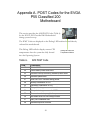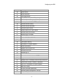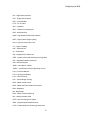
1
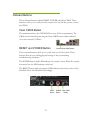
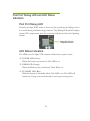
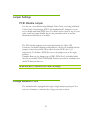
User’s Guide EVGA P55 Classified 200 Motherboard 1 2 EVGA P55 Classified 200 Motherboard Table of Contents User’s Guide .................................................................................................................1 EVGA P55 Classified 200 Motherboard........................................................................1 Before You Begin… ......................................................................................................7 Parts NOT in the Kit ................................................................................................. 7 EVGA P55 Classified 200 Motherboard.......................................................................8 Motherboard Specifications...................................................................................... 8 Hardware Installation ..................................................................................................10 Safety Instructions .................................................................................................. 10 Preparing the Motherboard .................................................................................... 11 Installing the CPU .............................................................................................. 11 Installing the CPU Fan ....................................................................................... 12 Installing System Memory (DIMMs) ................................................................... 13 Installing the Motherboard...................................................................................... 13 Installing the I/O Shield ...................................................................................... 14 Securing the Motherboard into a System Case ................................................. 15 Connecting Cables ................................................................................................. 15 24-pin ATX Power (PW1) ............................................................................... 16 8-pin ATX 12V Power (PW12) ....................................................................... 16 Connecting Serial ATA Cables........................................................................... 17 Connecting Internal Headers ............................................................................. 18 Front Panel Header ........................................................................................ 18 IEEE1394a (Firewire) ..................................................................................... 19 USB Headers ................................................................................................. 20 Audio .............................................................................................................. 21 3 Expansion Slots ................................................................................................. 22 PCI Express x16/x8/x4 Slots .......................................................................... 22 Onboard Buttons .................................................................................................... 23 Clear CMOS Button ....................................................................................... 23 RESET and POWER Button .......................................................................... 23 Post Port Debug LED and LED Status Indicators .................................................. 24 Post Port Debug LED ..................................................................................... 24 LED Status Indicators .................................................................................... 24 Jumper Settings ..................................................................................................... 25 PCIE Disable Jumper ..................................................................................... 25 Voltage Measure Point ........................................................................................... 25 EVGA Control Panel V2 (ECP) .............................................................................. 26 EVGA Show-Volt .................................................................................................... 31 Configuring the BIOS ..................................................................................................32 Enter BIOS Setup ................................................................................................... 33 Main Menu.............................................................................................................. 33 Standard BIOS Features Menu .............................................................................. 36 System Time / System Date............................................................................... 37 Advanced BIOS Features ...................................................................................... 37 IDE Configuration ............................................................................................... 38 Boot Settings Configuration ............................................................................... 38 AHCI Configuration ............................................................................................ 38 USB Configuration ............................................................................................. 39 Advanced Chipset Features ................................................................................... 39 North Bridge Configuration ................................................................................. 39 PCI Express Configuration ................................................................................. 40 Intel VT-d Configuration ..................................................................................... 40 ME Subsystem Configuration............................................................................. 41 PCI/PNP Resource Management .......................................................................... 42 4 EVGA P55 Classified 200 Motherboard Clear NVRAM ..................................................................................................... 42 Plug & Play O/S ................................................................................................. 42 PCI Latency Timer ............................................................................................. 42 Allocate IRQ to PCI VGA ................................................................................... 43 Palette Snooping ................................................................................................ 43 PCI IDE BusMaster ............................................................................................ 43 OffBoard PCI/ISA IDE Card ............................................................................... 43 IRQ Settings ....................................................................................................... 43 DMA Channel ..................................................................................................... 43 Reserved Memory Size ...................................................................................... 43 Boot Configuration Features .................................................................................. 44 Boot Device Priority ............................................................................................ 44 Hard Disk Drives ................................................................................................ 44 CD/DVD Drives .................................................................................................. 45 Power Management Features ................................................................................ 45 ACPI Configuration ............................................................................................ 45 SLP_S4# Min. Assertion Width .......................................................................... 46 Restore on AC Power Loss ................................................................................ 46 Hardware Health Configure.................................................................................... 46 H/W Health Function .......................................................................................... 47 CPU Fan Mode Setting ...................................................................................... 47 Frequency/Voltage Control Menu .......................................................................... 47 Memory Configure .............................................................................................. 48 CPU Configuration ............................................................................................. 48 Installing Drivers and Software ..................................................................................49 Windows XP/Vista/7 Driver Installation .................................................................. 49 Appendix A. POST Codes for the EVGA P55 Classified 200 Motherboard ...............50 5 List of Figures Figure 1. PW1 Motherboard Connector ................................................................ 16 Figure 2. CMOS Setup Utility Main Menu ............................................................. 34 Figure 3. Standard BIOS Features Menu .............................................................. 36 Figure 4. Advanced BIOS Features ...................................................................... 38 Figure 5. Advanced Chipset Features ................................................................... 39 Figure 6. PCI/PNP Resource Management .......................................................... 42 Figure 7. Boot Configuration Features .................................................................. 44 Figure 8. Power Management Features ................................................................ 45 Figure 9. Hardware Health Configure .................................................................... 46 Figure 10. Frequency/Voltage Control ................................................................ 47 6 EVGA P55 Classified 200 Motherboard Before You Begin… Parts NOT in the Kit This kit contains all the hardware necessary to install and connect your new EVGA P55 Classified 200 Motherboard. However, it does not contain the following items that must be purchased separately to make the motherboard functional. Intel Socket 1156 Processor DDR3 System Memory Socket 1156 or Socket 775 Cooling fan PCI Express or PCI Graphics Card Power Supply EVGA assumes you have purchased all the necessary parts needed to allow for proper system functionality. For a full list of supported CPU’s on this motherboard, please visit http://www.evga.com/support/motherboard/. When replacing a motherboard in a system case, you will need to reinstall an operating system even though the current hard disk may already have an operating system. 7 EVGA P55 Classified 200 Motherboard Motherboard Specifications Size ATX form factor of 12 inch x 10.375 inch Processor support Intel Socket 1156 CPU’s Operating systems: Supports Windows XP 32bit/64bit, Windows Vista 32bit/64bit, and Windows 7 32bit/64bit Intel P55 Express Chipset System Memory support Supports dual channel DDR3-2600+. Officially supports up to 16GBs of DDR3 memory. USB 2.0 Ports Supports hot plug Thirteen USB 2.0 ports (Seven rear panel ports, six onboard USB headers) Supports wake-up from S1 and S3 mode Supports USB 2.0 protocol up to a 480 Mbps transmission rate 8 Six(6) onboard Serial ATA II 300MBps data transfer rate Six Serial ATA II connectors with support for RAID 0, RAID 1, RAID 10, and RAID 5 Supports hot plug and NCQ (Native Command Queuing ) Dual Onboard LAN’s Integrated LAN port’s Supports 10/100/1000 Mb/sec Ethernet Onboard IEEE1394a (Firewire) Support hot plug Two IEEE1394a ports (One rear panel port, one onboard 1394 header) with a rate transmission of 400 Mbps Onboard Audio Realtek High-Definition audio Supports 8-channel audio Supports Jack-Sensing function Green Function Supports ACPI (Advanced Configuration and Power Interface) Supports S0 (normal), S1 (power on suspend), S3 (suspend to RAM), S4 (Suspend to disk - depends on OS), and S5 (soft - off) Expansion Slots Six PCI Express x4/x8/x16 slots 9 Hardware Installation This section will guide you through the installation of the motherboard. The topics covered in this section are: Preparing the motherboard Installing the CPU Installing the CPU fan Installing the memory Installing the motherboard Connecting cables Safety Instructions To reduce the risk of fire, electric shocks, and injury, always follow basic safety precautions. Remember to remove power off your computer by disconnecting the AC main source before removing or installing any equipment from/to the computer chassis. 10 Preparing the Motherboard Installing the CPU Be very careful when handling the CPU. Hold the processor only by the edges and do not touch the contacts on the motherboard or CPU. Any physical damage to the motherbard pins will void the warranty. Use the following procedure to install the CPU onto the motherboard: Unhook the socket lever by pushing down and away from the socket. Pull the socket lever back and the load plate will automatically lift. There is a protective socket cover within the CPU socket to protect the socket when there is no CPU installed. Remove the protective socket cover from the CPU Socket in a straight up motion. Note: It is a good idea to save the cover so that whenever you remove the CPU you have a safe place to store it. 11 Align the notches in the processor with the notches on the socket. Lower the processor straight down into the socket without tilting or sliding it into the socket Note: Make sure the CPU is fully seated and level. Lower the load plate so it is resting on the CPU. Align notches with notches on the CPU Pull back the socket lever again to ensure the load plate tip engages under the shoulder screw cap. Carefully close and latch the lever. Load plate tip under screw cap Installing the CPU Fan There are many different fan types that can be used with this motherboard. Follow the instruction that came with you fan assembly. Be sure that the fan orientation is correct for your chassis type and your fan assembly. Please note that there are 2 sets of mounting holes, the holes surrounded in white are to be used for Socket 1156 heatsinks and are labeled. The other holes are to be used for Socket 775 heatsinks. In most cases, the Socket 1156 mounting holes will be used. 12 Installing System Memory (DIMMs) Your new motherboard has four 240-pin slots for DDR3 memory. These slots support 256 MB, 512 MB, 1GB, 2GB, 4GB DDR3 technologies. There must be at least one memory bank populated to ensure normal operation. Use the following the recommendations for installing memory. (See Figure 1 on page 10 for the location of the memory slots.) One DIMM: If using 1 DIMM (Single Channel), install into: DIMM slot 1. Two DIMMs: If using 2 DIMMs (Dual Channel), install into: DIMM slots 1 and 3. Four DIMMS: If using 4 DIMMs (Dual Channel), install into: DIMM slots 2, 1, 4, and 3. DIMM Slot 2 DIMM Slot 1 DIMM Slot 4 DIMM Slot 3 Use the following procedure to install memory DIMMs. Note that there is only one gap near the center of the DIMM slot. This slot matches the slot on the memory DIMM to ensure the component is installed properly. 1. Unlock a DIMM slot by pressing the module clips outward. 2. Align the memory module to the DIMM slot, and insert the module vertically into the DIMM slot. The plastic clips at both sides of the DIMM slot automatically lock the DIMM into the connector. Installing the Motherboard The sequence of installing the motherboard into a system case depends on the chassis you are using and if you are replacing an existing motherboard or working with an empty system case. Determine if it would be easier to make all 13 the connections prior to this step or to secure the motherboard and then make all the connections. It is normally easier to secure the motherboard first. Use the following procedure to install the I/O shield and secure the motherboard into the chassis. Installing the I/O Shield The motherboard kit comes with an I/O shield that is used to block radio frequency transmissions, protects internal components from dust and foreign objects, and promotes correct airflow within the chassis. Before installing the motherboard, install the I/O shield from the inside of the chassis. Press the I/O shield into place and make sure it fits securely. 14 Securing the Motherboard into a System Case Most system cases have a base with mounting studs or spacers to allow the motherboard to be secured to the chassis and help to prevent short circuits. If there are studs that do not align with a mounting hole on the motherboard, it is recommended that you remove that stud to prevent the possibility of a short circuit. In most cases, it is recommended to secure the motherboard using a minimum of nine (9) spacers and screws. 1. Carefully place the motherboard onto the stand offs located inside the chassis. 2. Align the mounting holes with the stand offs. 3. Align the connectors to the I/O shield. 4. Ensure that the fan assembly is aligned with the chassis vents according to the fan assembly instruction. 5. Secure the motherboard with a recommended minimum of nine (9) screws. Connecting Cables This section takes you through all the necessary connections on the motherboard. This will include: Power Connections 24-pin ATX power (PW1) 8-pin ATX 12V power (PW12) Internal Headers Front panel IEEE 1394a USB Headers Audio Serial ATA II USB 2.0 Expansion slots CMOS Clear Button 15 24-pin ATX Power (PW1) is the main power supply connector located along the edge of the board next to the DIMM slots. Make sure that the power supply cable and pins are properly aligned with the connector on the motherboard. Firmly plug the power supply cable into the connector and make sure it is secure. PW1 PW1 connector Plug power cable from system power supply to PW1 Figure 1. PW1 Motherboard Connector Table 1. PW1 Pin Assignments Connector 1 13 Pin 12 24 Signal Pin Signal 1 +3.3V 13 +3.3V 2 +3.3V 14 -12V 3 GND 15 GND 4 +5V 16 PS_ON 5 GND 17 GND 6 +5V 18 GND 7 GND 19 GND 8 PWROK 20 RSVD 9 +5V_AUX 21 +5V 10 +12V 22 +5V 11 +12V 23 +5V 12 +3.3V 24 GND 8-pin ATX 12V Power (PW12) PW12, the 8-pin ATX 12V power connection, is used to provide power to the CPU. Align the pins to the connector and press firmly until seated. 16 Connecting Serial ATA Cables The Serial ATA II connector is used to connect the Serial ATA II device to the motherboard. These connectors support the thin Serial ATA II cables for primary storage devices. The current Serial ATA II interface allows up to 300MB/s data transfer rate. There are six (6) internal serial ATA connectors on this motherboard. These connections are designed to be angled to not interfere with any expansions cards. These connection points support RAID 0, RAID 1, and RAID 10 configurations. SATA 4 (bottom) SATA 2 (bottom) SATA 0 (bottom) SATA 5 (top) SATA 3 (top) SATA 1 (top) 17 Connecting Internal Headers Front Panel Header The front panel header on this motherboard is one connector used to connect the following four cables. (see Table 2 for pin definitions): PWRLED Attach the front panel power LED cable to these two pins of the connector. The Power LED indicates the system’s status. When the system is turned on, the LED is on. When the system is turned off, the LED is off. Note: Some system cases do not have all four cables. Be sure to match the name on the connectors to the corresponding pins. PWRSW Attach the power button cable from the case to these two pins. Pressing the power button on the front panel turns the system on and off rather than using the onboard button. Table 2.Front Panel Header Pins Pin No Connect 1 3 2 4 5 7 6 8 9 HD_PWR HD Active PWR LED STBY LED Ground RST BTN PWR BTN Ground +5V Empty 10 Empty HD_LED HD_LED Attach the hard disk drive indicator LED cable to these two pins. The HDD indicator LED indicates the activity status of the hard disks. PWRLED RESET PWRSW RESET Attach the Reset switch cable from the front panel of the case to these two pins. The system restarts when the RESET switch is pressed. 18 Signal IEEE1394a (Firewire) This motherboard has one IEEE 1394a onboard header. Alternatively, you can also connect this to your system case (if applicable). 1. Secure the bracket to either the front or rear panel of the system case (not all system cases are equipped with the front panel option). Connect the end of the cable to the IEEE1394a header on the motherboard. Table 3. IEEE 1394a Connector Pins Connector IEEE 1394a Connector 10 8 6 4 2 9 7 5 3 1 Pin 1 2 3 4 5 6 7 8 9 10 Signal TPA+ TPAGND GND TPB+ TPB+12V +12V Empty GND 19 USB Headers This motherboard contains seven (7) USB 2.0 ports that are exposed on the rear panel of the chassis (Figure 2). The motherboard also contains three (3) 10pin internal header connectors onboard that can be used to connect an optional external bracket containing up to six (6) USB 2.0 ports. 1. Secure the bracket to either the front or rear panel of your chassis (not all chassis are equipped with the front panel option). 2. Connect the end of the cable(s) to the USB 2.0 header on the motherboard. Table 4. USB 2.0 Header Pins Connector Pin USB 2.0 Header Connector 1 5V_DUAL 3 D- 5 D+ 7 GND 9 Empty Pin 20 Signal Signal 2 5V_DUAL 4 D- 6 D+ 8 GND 10 No Connect Audio The audio connector supports HD audio standard and provides two kinds of audio output choices: the Front Audio, the Rear Audio. The front Audio supports re-tasking function. Table 5. Front Audio Connector Connector Front Audio Connector 10 8 6 4 2 9 7 5 3 1 Pin 1 Signal PORT1_L 2 AUD_GND 3 PORT1_R 4 PRECENCE_J 5 PORT2_R 6 SENSE1_RETURN 7 SENSE_SEND 8 Empty 9 PORT2_L 10 SENSE2_RETURN 21 Expansion Slots PCI Express x16/x8/x4 Slots These PCI Express slots are reserved for Graphic Cards and PCI Express x1 and x4 devices. The design of this motherboard supports multiple Graphic Card technology. When installing a PCI Express Graphic Card, be sure the retention clip snaps and locks the card into place. If the card is not seated properly, it could cause a short across the pins. Secure the card’s metal bracket to the chassis back panel with the screw used to hold the blank cover. 22 Onboard Buttons These onboard buttons include RESET, POWER and Clear CMOS. These functions allow you to easily reset the system, turn on/off the system, or clear the CMOS. Clear CMOS Button The motherboard uses the CMOS RAM to store all the set parameters. The CMOS can be cleared by pressing the Clear CMOS button either onboard or on the external I/O Panel. RESET and POWER Button External Clear CMOS Button These onboard buttons allow you to easily turn on/off the system. These buttons allow for easy debugging and testing of the system during troubleshooting situations. The POWER button with LED indicates the system’s status. When the system is powered on, the LED remains a solid red. The RESET button with an integrated LED indicates the activity status of the hard disk drives and will flicker accordingly. RESET Button 23 POWER Clear CMOS Button Button Post Port Debug LED and LED Status Indicators Post Port Debug LED Provides two-digit POST codes to show why the system may be failing to boot. It is useful during troubleshooting situations. This Debug LED will also display current CPU temperatures after the system has fully booted into the Operating System. Debug LED with CPU Temperature Monitor LED Status Indicators The LEDs near the 24pin ATX connector indicate the system’s status. POWER LED (Green): When the System is powered on: This LED is on. DIMM LED (Orange): When the Memory slot is functional: This LED is on. STANDBY LED (Blue): When the System is in Standby Mode: This LED is on. This LED will remain on as long as the motherboard is receiving constant power. 24 Jumper Settings PCIE Disable Jumper For the ease of troubleshooting Multiple Video Cards, or testing individual Video Card’s Overclocking, EVGA has implemented 3 Jumpers you can use to disable individual PCIE slots. You don’t need to remove any of your video cards but simply disable the slot the particular card is in and the Motherboard will treat it as invisible. The PCIe disable jumpers are located right beside the 24pin ATX Connector. In default shipping configurations, all slots are enabled with the jumpers in the left position. From top to bottom, PCIE slots 1,2,3 respectively. To disable a PCIE Slot, move the jumper over to the right position. Example: Remove the Jumper cap of JPE2, PCIE Slot 2 is disabled while the rest are enabled. The PCIE Disable Function can also be extended onto the ECP discussed later on. Do this when the PC is turned off, NOT when it is running! Voltage Measure Point The motherboard is equipped with eight voltage measure point pad. You can use a voltmeter to measure the voltage you want to know. 25 CPU Vcore voltage CPU VTT voltage Memory voltage P55 chipset voltage CPU PLL voltage Ground EVGA Control Panel V2 (ECP) For the convenience of users, EVGA has bundled an easy to Access Control Panel: To use the ECP, simply hook up the black ECP Cable to the motherboard at the ECP header location. (See visual guide) The other end of the Cable should be connected to the ECP as shown: 26 **Before turning on the PC, please check to see that the CPU VCore Booster is in the Off position clicked up.** If you wish to access the PCIE Disable Function via the ECP, please follow these instructions: Locate the PCIE Disable Jumpers (see visual guide) Remove the 3 jumpers. Connect the PCIE Cable with the Red wires occupying the left most pins: 27 It doesn’t matter which end of the PCIE Cable goes onto the Motherboard. Please be reminded to do this when PC is not running. Next, connect the other end of PCIE Cable onto the ECP as shown: 28 The Red wires should be occupying the pins on the top row. Now, access the Disable/Enable Function at the front of the Control Panel: From Right to Left, PCIE Slots 1,2,3. When Jumper is in top position, PCIE slot is enabled. When in bottom position PCIE slot is disabled. Above shows example of PCIE slot 2 disabled while the rest are enabled. 29 CPU VCore Booster For convenience of users when overclocking, the ECP houses 3 CPU Vcore Boosters for real-time boost of CPU VCore upwards of +0.1v per button. The Red LED will light up when VCore booster is pressed. When one Red LED is lit, VCore is boosted by +0.v. When 2 Red LEDs are lit, VCore is boosted by +0.2v. To stop the VCore boost, just press again and VCore will go down to what you have set. The 2 buttons are exactly the same in function each. Vtt Booster The far right button on the EVGA ECP increases the VTT voltage by +0.1v. 30 EVGA Show-Volt EVGA Show-Volt is another innovative feature of the EVGA P55 Classified motherboard. It is extremely useful for Enthusiasts and Technically inclined users for troubleshooting ad overclock testing. This is located at the top right hand corner of your motherboard. To use this feature, insert the connector end of the red meter probe into the post as seen below, when power is applied to the motherboard, the voltage meter will show the voltages that you make contact with on the probe. Note: It is very important to take a special caution when probing, you do not want to short anything else. Note: The voltage meter reads 0 to 13v DC, do not use it for AC measurement. 31 Configuring the BIOS This section discusses how to change the system settings through the BIOS Setup menus. Descriptions of the BIOS parameters are also provided. This section includes the following information: Enter BIOS Setup Main Menu Standard BIOS Features Advanced BIOS Features Advanced Chipset Features PCI/PnP Resource Management Boot Configuration Features Power Management Features Hardware Health Configure Frequency/Voltage Control 32 Configuring the BIOS Enter BIOS Setup The BIOS is the communication bridge between hardware and software. Correctly setting the BIOS parameters is critical to maintain optimal system performance and stability. Use the following procedure to verify/change BIOS settings. 3. Power on the computer. 4. Press the Del key when the following message briefly displays at the bottom of the screen during the Power On Self Test (POST). Press F2 to Load Defaults, DEL to enter Setup. Pressing Del takes you to the AMI BIOS CMOS Setup Utility. Main Menu The main menu allows you to select from the list of setup functions and two exit choices. Use the + and - keys to scroll through the options or press Enter to display the associated submenu. Use the arrow keys to position the selector in the option you choose. To go back to the previous menu, press Esc. 33 CMOS Setup Utility – Copyright (C) 1985-2005, American Megatrends Hardware Health Configure Standard BIOS Features Frequency/Voltage Control Advanced BIOS Features Advanced Chipset Features Load Optimal Defaults PCI/PNP Resource Management Discard Changes Boot Configuration Features Save & Exit Setup Power Management Features Discard Changes and Exit : Move Enter:Select +/-/:Valve F10:Save ESC:Exit F1: General Help F7:Previous Values F9: Optimized Defaults Configure Time and Date. Display System Information... v02.67 (C)Copyright 1985-2009, American Megatrends, Inc. Figure 2. CMOS Setup Utility Main Menu Standard BIOS Features Use this menu to set up the basic system configuration. Advanced BIOS Features Use this menu to set up the advanced system features and boot sequence. Advanced Chipset Features Use this menu to set up onboard peripherals such as IDE, RAID, USB, LAN, and MAC control. PCI/PNP Resource Management Use this menu to configure resource management. Boot Configuration Features Use this menu to modify the system’s boot configuration. Power Management Features Use this menu to modify power management, power on, and sleep features. Hardware Health Configure Use this menu to view system vitals. Frequency/Voltage Control Use this menu to optimize system performance and configure clocks, voltages, memory timings, and more. 34 Configuring the BIOS Load Optimal Defaults Load default system settings. Discard Changes Use this command to abandon all setting changes and exit setup. Save Changes & Exit Use this command to save settings to CMOS and exit setup. Discard Changes and Exit Use this command to abandon all setting changes and exit setup. 35 Standard BIOS Features Menu The Standard CMOS Features menu is used to configure the standard CMOS information, such as the date, time, and so on. Use the + and - keys to scroll through the options. Use the arrow keys to position the selector in the option you choose. To go back to the previous menu, press Esc. CMOS Setup Utility – Copyright (C) 1985-2005, American Megatrends Standard BIOS Features System Overview ______________________________________________ AMIBIOS Version :08.00.16 Build Date:07/16/10 ID :1E658A19 Processor Intel(R) Core(TM) CPU Speed :2666MHz Count :1 Help Item Use [ENTER] , [TAB] Or [SHIFT-TAB] to select a field. Use [+] or [-] to Configure system Time. 750 @ 2.67GHz System Memory Size :4088MB System Time System Date [13:37:00] [Fri 07/16/2010] :Move Enter:Select F7:Previous Values Figure 3. +/-/:Value F10:Save ESC:Exit F1:General Help F9:Optimized Defaults Standard BIOS Features Menu 36 Configuring the BIOS System Time / System Date Using the arrow keys, position the cursor over the month, day, and year. Use the + and - keys to scroll through dates and times. Note that the weekday (Sun through Sat) cannot be changed. This field changes to correspond to the date you enter. Note that the hour value is shown in a 24-hour clock format. Time is represented as hour : minute : second. System Time System Date [13:37:00] [Fri 07/16/2010] Time (hh:mm:ss) 14 : 48: 43 Advanced BIOS Features Access the Advanced BIOS Features menu from the CMOS Setup Utility screen. Use the + and - keys to scroll through the options or press Enter to display the sub-menu. Use the arrow keys to position the selector in the option you choose. To go back to the previous menu, press Esc. The options that have associated sub-menus are designated by a , which precedes the option. Press Enter to display the sub-menus. 37 CMOS Setup Utility – Copyright (C) 1985-2005, American Megatrends Advanced BIOS Features Advanced Settings ______________________________________________ WARNING: Setting wrong values in below sections may cause system to malfunction. IDE Configuration [Press Boot Settings Configuration[Press AHCI Configuration [Press USB Configuration [Press :Move Enter:Select F7:Previous Values Figure 4. +/-/:Value Enter] Enter] Enter] Enter] F10:Save Help Item Main Level Select Removable Boot Device Priority ESC:Exit F1:General Help F9:Optimized Defaults Advanced BIOS Features IDE Configuration Use this to configure your storage drivers and to enable RAID or switch between IDE and AHCI mode. Please note for Windows Vista / Windows 7, it is recommended to use AHCI mode for new system installations. Boot Settings Configuration Use this option to configure various system options, such as Bootup Num-Lock status, Quiet Boot and other advanced features. AHCI Configuration This menu will allow you to change advanced AHCI settings, such as S.M.A.R.T. status and more. 38 Configuring the BIOS USB Configuration This option menu allows you to enable Legacy USB support, force USB 1.1 mode and more. Advanced Chipset Features Select Advanced Chipset Features from the CMOS Setup Utility menu and press Enter to change the settings. CMOS Setup Utility – Copyright (C) 1985-2005, American Megatrends Advanced Chipset Features Advanced Chipset Settings ______________________________________________ WARNING: Setting wrong values in below sections may cause system to malfunction. Help Item Configure North Bridge features. North Bridge Configuration [Press Enter] PCI Express Configuration [Press Enter] Intel VT-d [Disabled] HD Audio Controller [Enabled] IEEE1394 [Enabled] LAN1 Controller [Enabled] LAN2 Controller [Enabled] LAN Boot [Disabled] ESATA Controller [Enabled] ESATA Boot [Disabled] PE1 Slot [Auto] P80 Show CPU Temperature Slot[Enabled] ME Subsystem Configuration [Press Enter] :Move Enter:Select F7:Previous Values Figure 5. +/-/:Value F10:Save ESC:Exit F1:General Help F9:Optimized Defaults Advanced Chipset Features North Bridge Configuration This option menu will allow you to set the primary graphics adapter, and more. 39 PCI Express Configuration This option menu will allow you to set advanced PCI Express options, such as Payload size. It is not recommended to adjust these settings. Intel VT-d Configuration This option menu allows you to enable, or disable, Virtualization Technology for Directed I/O. This setting can help improve performance in a virtualized environment, it is recommended to leave this disabled for standard system setups. The Advanced Chipset Features menu also allows you to enable/disable some onboard devices, they are as follows: HD Audio Controller Use this function to set the onboard audio function. It is recommended to leave this enabled, unless you are using an external sound, add-on sound card. IEEE1394 This function allows you to enable or disable the IEEE1394 (Firewire) interface. LAN1 Controller This function allows you to enable or disable the onboard primary network controller. It is recommended to leave this enabled, unless you are using an external Network Controller, such as an EVGA Killer Xeno card. LAN2 Controller This function allows you to enable or disable the onboard secondary network controller. It is recommended to leave this enabled, unless you are using an external Network Controller, such as an EVGA Killer Xeno card. ESATA Controller This function allows you to enable or disable the SATA interface. PE1 Slot This function allows you to enable or disable the PE1 Slot. P80 Show CPU Temperature When this function is enabled the onboard Post Port LED will display the CPU temperature. 40 Configuring the BIOS ME Subsystem Configuration Select this option to change advanced ME Subsystem settings. 41 PCI/PNP Resource Management Select PCI/PNP Resource Management from the CMOS Setup Utility menu and press Enter to display the advanced settings. CMOS Setup Utility – Copyright (C) 1985-2005, American Megatrends PCI/PNP Resource Management Advanced PCI/PnP Settings ______________________________________________ WARNING: Setting wrong values in below sections may cause system to malfunction. Clear NVRAM Plug & Play O/S PCI Latency Timer Allocate IRQ to PCI VGA Palette Snooping PCI IDE BusMaster OffBoard PCI/ISA IDE Card IRQ3 IRQ4 IRQ5 IRQ7 IRQ9 IRQ10 :Move Enter:Select F7:Previous Values Figure 6. Help Item Clear NVRAM during System Boot. [No] [No] [64] [Yes] [Disabled] [Enabled] [Auto] [Available] [Available] [Available] [Available] [Available] [Available] +/-/:Value F10:Save ESC:Exit F1:General Help F9:Optimized Defaults PCI/PNP Resource Management Clear NVRAM This function clears the NVRAM during System Boot. Plug & Play O/S This function sets whether the O/S or BIOS configures Plug and Play devices. A setting of [No] is default. PCI Latency Timer This function sets the value in units of PCI clocks. 42 Configuring the BIOS Allocate IRQ to PCI VGA This function allows an IRQ to be assigned to a PCI VGA. Palette Snooping This function allows the BIOS to inform the system that an ISA graphics device is installed. PCI IDE BusMaster This function allows the BIOS to use PCI BusMastering for reading or writing to IDE drives. OffBoard PCI/ISA IDE Card This function allows manual override of PCI/ISA external cards. A setting of [Auto] works for most devices. IRQ Settings The various IRQ settings allows you to reserve IRQ’s if necessary, it is recommended to leave this as Available. DMA Channel The various DMA settings allow you to specify a DMI to be used by PCI/PnP devices. Reserved Memory Size This option allows you to specify the size of the memory block to reserve for legacy ISA devices. 43 Boot Configuration Features Select Boot Configuration Features from the CMOS Setup Utility menu and press Enter to display the settings. CMOS Setup Utility – Copyright (C) 1985-2005, American Megatrends Boot Configuration Features Boot Device Priority Hard Disk Drives CD/DVD Drives [Press Enter] [Press Enter] [Press Enter] Help Item Specifies the Boot Device Priority sequence. :Move Enter:Select +/-/:Value F10:Save ESC:Exit F1:General Help F7:Previous Values F9:Optimized Defaults :Move Enter:Select +/-/PU/PD:Value F10:Save ESC:Exit F1:General Help F5:Previous Values F6:Fail-Safe Defaults F7:Optimized Defaults Figure 7. Boot Configuration Features Boot Device Priority This option menu will allow specification of the boot device priority sequence. Hard Disk Drives This option menu allows you specification of the Hard Disk boot priority sequence. 44 Configuring the BIOS CD/DVD Drives This option menu allows you specification of the CD/DVD boot priority sequence. Power Management Features Select Power Management Features from the CMOS Setup Utility menu and press Enter to display the settings. CMOS Setup Utility – Copyright (C) 1985-2005, American Megatrends Power Management Features Power Management Features ______________________________________________ ACPI Configuration [Press Enter] SLP_S4# Min. Assertion Width [4 to 5 seconds] Help Item Section for Advanced ACPI Configuration. :Move Enter:Select +/-/:Value F10:Save ESC:Exit F1:General Help F7:Previous Values F9:Optimized Defaults :Move Enter:Select +/-/PU/PD:Value F10:Save ESC:Exit F1:General Help F5:Previous Values F6:Fail-Safe Defaults F7:Optimized Defaults Figure 8. Power Management Features ACPI Configuration This menu will allow adjustment of Advanced ACPI configurations. 45 SLP_S4# Min. Assertion Width This function allows adjustment of the SLP assertion width. Restore on AC Power Loss This menu allows adjustment of the AC Power Loss parameters. Hardware Health Configure Select Hardware Health Configure from the CMOS Setup Utility menu and press Enter to display the settings. CMOS Setup Utility – Copyright (C) 1985-2005, American Megatrends Hardware health Configure Hardware Health Configure H/W Health Function [Enabled] ______________________________________________ CPU Temperature Sensor VREG Temperature Sensor System Temperature Sensor :34C/93F :48C/118F :34C/93F CPU Fan Speed Power Fan Speed Chassis Fan Speed :3264 RPM :1337 RPM :3864 RPM VCore Memory CPU VTT PCH +5V :1.337 :1.481 :1.021 :1.031 :4.961 Help Item Enables Hardware Health Monitoring Device. V V V V V :Move Enter:Select +/-/:Value F10:Save ESC:Exit F1:General Help F7:Previous Values F9:Optimized Defaults :Move Enter:Select +/-/PU/PD:Value F10:Save ESC:Exit F1:General Help F5:Previous Values F6:Fail-Safe Defaults F7:Optimized Defaults Figure 9. Hardware Health Configure 46 Configuring the BIOS H/W Health Function This will enable or disable Hardware Health Monitoring. CPU Fan Mode Setting This function allows change of the fan mode configuration. Frequency/Voltage Control Menu Select Frequency/Voltage Control from the CMOS Setup Utility menu and press Enter to display the settings. CMOS Setup Utility – Copyright (C) 1985-2005, American Megatrends Frequency/Voltage Control Menu Memory Configure CPU Configuration [Press Enter] [Press Enter] Item Help Dummy O.C [Disabled] Target CPU Frequency : 2933 MHz Target Memory Frequency : 1333 MHz CPU Multiplier Setting [21] CPU Frequency Setting [Auto] PCIE Frequency Setting [100] QPI Frequency Selection [Auto] MCH Strap [Auto] Main Level Extreme Cooling [Disabled] EVGA VDroop Control [With VDroop] Current CPU VCore : 1.20000V Bootup CPU VCore [Auto] Eventual CPU VCore [Auto] Current Dimm Voltage : 1.50V :Move Enter:Select F7:Previous Values Figure 10. +/-/:Value F10:Save ESC:Exit F1:General Help F9:Optimized Defaults Frequency/Voltage Control 47 Memory Configure This menu will allow the configuration of advanced memory timings, including memory frequency and memory timings. CPU Configuration This menu will allow the configuration of advanced CPU settings, such as Virtualization Technology, CPU SpeedStep, or CPU power saving options. 48 Configuring the BIOS Installing Drivers and Software The CD that has been shipped with the EVGA P55 Classified 200 Motherboard contains the following software and drivers: Chipset Drivers Audio drivers LAN Drivers RAID Drivers EVGA E-LEET Overclocking Utility Adobe Acrobat Reader User’s Manual Windows XP/Vista/7 Driver Installation 1. Insert the Intel P55 installation CD for the motherboard included in the kit. 2. The CD will autorun, install the drivers and utilities listed on the install screen. If the CD does not run, go to My Computer and click on the CD to open. 49 Appendix A. POST Codes for the EVGA P55 Classified 200 Motherboard This section provides the AMI POST Codes (Table 6) for the EVGA P55 Classified 200 Motherboard during system boot up. The POST Codes are displayed on the Debug LED readout located directly onboard the motherboard. This Debug LED will also display current CPU temperatures after the system has fully booted into the Operating System. Table 6. Code Debug LED with CPU Temperature Monitor AMI POST Code Description 03 Initialize BIOS. 04 Check Battery Power and CMOS 05 Initialize interrupt controlling hardware/vector table 06 Initialize system timer 07 Fixes CPU POST interface calling pointer 08 Primary initialization of CPU C0 Secondary initialization of CPU C1 Set up boot strap processor information C2 Set up boot strap processor for POST C5 Enumerate and set up application processors C6 Re-enable cache for boot strap processor C7 Early CPU initialization exit 0A Initialize keyboard controller 50 Configuring the BIOS Code Description 0B Detect Mouse 0C Detect Keyboard 0E Test input devices 13 Early POST initialization of chipset registers 20 Relocate System Management interrupt vector 24 Uncompress and initialize BIOS module 2A Initialize devices primary 2C Initialize devices secondary 2E Initialize output devices 31 Allocate memory for ADM module 33 Initialize silent boot module 37 Display sign-on message 38 Initialize USB controller 39 Initialize DMAC-1 & DMAC-2 3A Initialize real time clock 3B Test system memory 3C Initialization of chipset registers 40 Detect coprocessor 52 Update CMOS memory size 60 Initialize NUM-LOCK 75 Initialize Int-13 78 Initialize IPL devices 7C Generate and write contents of ESCD 84 Log errors encountered 85 Display errors, if no display check monitor/video card 87 Execute BIOS setup if needed or requested 8C Late POST initialization of chipset registers 8D Build ACPI tables 8E Program peripheral parameters 90 Initialize system management interrupt A1 Prepare for system boot 51 Code Description A2 Initialize IRQ routing table A4 Display boot option popup A7 Display system configuration screen A9 Wait for user input at configuration display AA Uninstall POST vector AB Prepare BBS for Int 19 boot AC End of POST initialization B1 Save system context for ACPI 00 Pass control to OS (can vary) Show CPU Temp (if enabled) EVGA Glossary of Terms ACPI - Advanced Configuration and Power Interface AFR – Alternate Frame Rendering APIC - Advanced Programmable Interrupt Controller BIOS - Basic Input Output System CD-ROM - Compact Disc Read-Only Memory CMOS - Complementary Metal-Oxide Semiconductor CPU – Central Processing Unit D-ICE – Dry Ice Cooling DDR2 - Double Data Rate 2 DDR3 - Double Data Rate 3 DIMM - Dual In-line Memory Module DRAM - Dynamic random access memory DVD - Digital Versatile Disc 52 Configuring the BIOS DVI – Digital Video Interface FDC - Floppy Disk Controller FSB – Front Side Bus FTW – For The Win! GHz – Gigahertz GPU – Graphics Processing Unit HDD - Hard Disk Drive HDMI - High-Definition Multimedia Interface HDR – High Dynamic Range Lighting HPET - High Precision Event Timer HT – Hyper-Threading HSF - Heat Sink Fan I/O - Input/Output IDE - Integrated Drive Electronics IEEE - Institute of Electrical and Electronics Engineers IGP - Integrated Graphics Processors IRQ - Interrupt Request JBOD - Just a Bunch of Disks JEDEC - Joint Electron Device Engineering Council LAN - Local Area Network LCD - Liquid Crystal Display LGA – Land Grid Array LN2 – Liquid Nitrogen Cooling MAC - Media Access Control MCP - Media and Communications Processor MHz - Megahertz NB - Northbridge NCQ - Native Command Queuing NIC - Network Interface Card NTFS - New Technology File System OEM - Original Equipment Manufacturer PATA - Parallel Advanced Technology Attachment 53 PCB - Printed Circuit Board PCI - Peripheral Component Interconnect PCIe - Peripheral Component Interconnect Express PCI-x - Peripheral Component Interconnect Extended POST – Power on Self Test PWM – Pulse Width Modulation QDR - Quad Data Rate QPI – Quick Path Interconnect RAID - Redundant Array of Inexpensive Disks RGB - Red Green Blue SATA - Serial Advanced Technology Attachment SB - Southbridge SCSI - Small Computer System Interface SFR – Split Frame Rendering SLI - Scalable Link Interface SPD - Serial Presence Detect SPDIF - Sony/Philips Digital Interconnect Format SPP - System Platform Processors TCP/IP - Transmission Control Protocol/Internet Protocol USB - Universal Serial Bus VDroop - V-core Voltage Drop VGA - Video Graphics Array 54