1
TOSHIBA
TOSHIBA
TOSHIBA
T201128-EN
4200/4300 Series USER'S MANUAL
*T201128-EN*
U S E R ' S M A N UA L
Model
4200/4300 Series
R
Copyright
© 2000 by Toshiba Corporation. All rights reserved. Under the copyright
laws, this manual cannot be reproduced in any form without the prior
written permission of Toshiba. No patent liability is assumed, with respect
to the use of the information contained herein.
Toshiba Satellite Pro 4200/4300 Series Portable Personal Computer
User’s Manual
First edition January 2000
Disclaimer
This manual has been validated and reviewed for accuracy. The
instructions and descriptions it contains are accurate for the Satellite Pro
4200/4300 Series Portable Personal Computers at the time of this
manual’s production. However, succeeding computers and manuals are
subject to change without notice. Toshiba assumes no liability for damages
incurred directly or indirectly from errors, omissions or discrepancies
between the computer and the manual.
Trademarks
IBM is a registered trademark and IBM PC, OS/2, and PS/2 are
trademarks of International Business Machines Corporation.
Pentium is a registered trademark of Intel Corporation.
MS-DOS, Microsoft, Windows, Windows NT and DirectX are registered
trademarks of Microsoft Corporation.
Sound Blaster and Pro are trademarks of Creative Technology Ltd.
Novell and NetWare are registered trademarks of Novell, Inc.
UNIX is a registered trademark of X/Open Company Ltd.
LapLink is a registered trademark of Travelling Software Inc.
RingCentral is a trademark of Motorola, Inc.
Centronics is a registered trademark of Centronics Data Computer
Corporation.
Photo CD is a trademark of Eastman Kodak.
DVDExpress is a trademark of National Semiconductor Corporation.
K56 flex is a trademark of lucent technologies and Rockwell Semiconductor
Systems.
Other trademarks and registered trademarks not listed above may be used
in this manual.
ii
User's Manual
Satellite Pro 4200/4300 User's Manual – 4200_UK.doc – ENGLISH – Printed on 27/01/00 as IM_420UK
Version
1
Last Saved on 27/01/00 18:20
EU Declaration of Conformity
This product carries the CE-Mark in accordance with the related European
Directives. CE-Marking is the responsibility of Toshiba Europe,
Hammfelddamm 8, 41460 Neuss, Germany.
User's Manual
Satellite Pro 4200/4300 User's Manual – 4200_UK.doc – ENGLISH – Printed on 27/01/00 as IM_420UK
iii
BLANK PAGE
iv
User's Manual
Satellite Pro 4200/4300 User's Manual – 4200_UK.doc – ENGLISH – Printed on 27/01/00 as IM_420UK
Version
1
Last Saved on 27/01/00 18:20
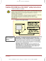
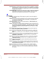
Toshiba DVD-ROM drive SD-C2302** safety instructions
**means any letters or numbers.
The DVD-ROM drive employs a laser system. To ensure proper use of this
product, please read this instruction manual carefully and retain for future
reference. Should the unit ever require maintenance, contact an
authorised service location.
Use of controls, adjustments or the performance of procedures other than
those specified may result in hazardous radiation exposure.
To prevent direct exposure to the laser beam, do not try to open
the enclosure.
Location of the required label
CAUTION: This appliance contains a laser system and is
classified as a “CLASS 1 LASER PRODUCT”. To use this
model properly, read the instruction manual carefully and keep
this manual for your future reference. In case of any trouble
with this model, please contact your nearest “AUTHORISED
service station”. To prevent direct exposure to the laser beam,
do not try to open the enclosure.
CAUTION: USE OF CONTROLS OR ADJUSTMENTS OR
PERFORMANCE OF PROCEDURES OTHER THAN THOSE
SPECIFIED IN THE OWNER’S MANUAL MAY RESULT IN
HAZARDOUS RADIATION EXPOSURE.
User's Manual
Satellite Pro 4200/4300 User's Manual – 4200_UK.doc – ENGLISH – Printed on 27/01/00 as IM_420UK
v
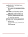
TEAC CD-ROM drive CD-224E safety instructions
The CD-ROM drive employs a laser system. To ensure proper use of this
product, please read this instruction manual carefully and retain for future
reference. Should the unit ever require maintenance, contact an
authorised service location.
Use of controls, adjustments or the performance of procedures other than
those specified may result in hazardous radiation exposure.
To prevent direct exposure to the laser beam, do not try to open the
enclosure.
Location of the required label
CAUTION: This appliance contains a laser system and is
classified as a “CLASS 1 LASER PRODUCT”. To use this
model properly, read the instruction manual carefully and keep
this manual for your future reference. In case of any trouble
with this model, please contact your nearest “AUTHORISED
service station”. To prevent direct exposure to the laser beam,
do not try to open the enclosure.
CAUTION: USE OF CONTROLS OR ADJUSTMENTS OR
PERFORMANCE OF PROCEDURES OTHER THAN THOSE
SPECIFIED IN THE OWNER’S MANUAL MAY RESULT IN
HAZARDOUS RADIATION EXPOSURE.
vi
User's Manual
Satellite Pro 4200/4300 User's Manual – 4200_UK.doc – ENGLISH – Printed on 27/01/00 as IM_420UK
Version
1
Last Saved on 27/01/00 18:20
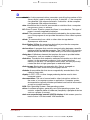
Toshiba CD-ROM drive XM-1902B safety instructions
The CD-ROM drive employs a laser system. To ensure proper use of this
product, please read this instruction manual carefully and retain for future
reference. Should the unit ever require maintenance, contact an
authorised service location.
Use of controls, adjustments or the performance of procedures other than
those specified may result in hazardous radiation exposure.
To prevent direct exposure to the laser beam, do not try to open the
enclosure.
Location of the required label
CAUTION: This appliance contains a laser system and is
classified as a “CLASS 1 LASER PRODUCT”. To use this
model properly, read the instruction manual carefully and keep
this manual for your future reference. In case of any trouble
with this model, please contact your nearest “AUTHORISED
service station”. To prevent direct exposure to the laser beam,
do not try to open the enclosure.
CAUTION: USE OF CONTROLS OR ADJUSTMENTS OR
PERFORMANCE OF PROCEDURES OTHER THAN THOSE
SPECIFIED IN THE OWNER’S MANUAL MAY RESULT IN
HAZARDOUS RADIATION EXPOSURE.
User's Manual
Satellite Pro 4200/4300 User's Manual – 4200_UK.doc – ENGLISH – Printed on 27/01/00 as IM_420UK
vii
General Precautions
Toshiba computers are designed to optimise safety, minimise strain and
withstand the rigours of portability. However, certain precautions should be
observed to further reduce the risk of personal injury or damage to the
computer.
Be certain to read the general precautions below and to note the cautions
included in the text of the manual.
Stress injury
Carefully read the Safety Instruction Manual. It contains information on
prevention of stress injuries to your hands and wrists that can be caused
by extensive keyboard use. Chapter 3, Getting Started, also includes
information on work space design, posture and lighting that can help
reduce physical stress.
Heat Warning
The base of the PC can become very warm; while the temperature will not
be too hot to the touch, prolonged physical contact may result in a
temporary heat imprint on the skin. It is recommended that prolonged
physical contact is avoided.
Also, if the computer has been used for a long time, avoid direct contact
with the metal plate supporting the I/O ports. It can become hot.
Mobile phones
Use of mobile phones can interfere with the PC sound system. The PC
operation is not impaired but it is recommended that a distance of 30 cm is
maintained between the PC & the mobile phone.
Pressure or impact damage
Do not apply heavy pressure to the computer or subject it to strong impact.
Excessive pressure or impact can cause damage to computer
components or otherwise cause malfunctions.
PC card overheating
Some PC cards can become hot with prolonged use. If two cards are
installed, both can become hot even if only one is used extensively.
Overheating of a PC card can result in errors or instability in the PC card
operation. Also, be careful when you remove a PC card that has been
used for a long time.
viii
User's Manual
Satellite Pro 4200/4300 User's Manual – 4200_UK.doc – ENGLISH – Printed on 27/01/00 as IM_420UK
Version
1
Last Saved on 27/01/00 18:20
CE compliance
This product and the original options are designed to observe the related
EMC (Electromagnetic compatibility) and safety standards. However,
Toshiba should not guarantee that this product still observes these EMC
standards if options or cables not produced by Toshiba are connected or
implemented. In this case the persons who have connected / implemented
those options / cables have to assure that the system (PC plus options /
cables) still fulfils the required standards. To avoid in general EMC
problems following advice should be observed:
Only CE marked options should be connected / implemented
Only best shielded cables should be connected
Working environment
This product was designed to fulfil the EMC (electromagnetic compatibility)
requirements to be observed for so-called "Residential, commercial and
light industry environments".
Toshiba do not approve the use of this product in working environments
other than the above mentioned "Residential, commercial and light
industry environments".
For example, the following environments are not approved:
Industrial Environments (environments with a mains voltage >230V~)
Medical Environments
Automotive Environments
Aircraft Environments
If this product is supplied with a network port, please refer to the
paragraph "Network connection".
Any consequences resulting from the use of this product in working
environments that are not approved are not the responsibility of Toshiba
Europe GmbH.
The consequences of the use of this product in non-approved working
environments may be:
Interference with other devices or machines in the near surrounding area
Malfunction of, or data loss from, this product caused by disturbances
generated by other devices or machines in the near surrounding area
Therefore Toshiba strongly recommend that the electromagnetic
compatibility of this product should be suitably tested in all non-approved
working environments before use. In the case of automobiles or aircraft,
the manufacturer or airline respectively should be asked for permission
before use of this product.
Furthermore, for general safety reasons, the use of this product in
environments with explosive atmospheres is not permitted.
User's Manual
Satellite Pro 4200/4300 User's Manual – 4200_UK.doc – ENGLISH – Printed on 27/01/00 as IM_420UK
ix
Network connection (class A warning)
If this product has networking capabilities and will be connected to a
network, Class A radiation limits will be observed (in accordance with
technical conventions). This means that if the product will be used in a
domestic environment, other devices in the near surrounding may suffer
interference. Consequently, please do not use this product in such
environments (for example a living room), otherwise you could be held
responsible for any ensuing interference.
Conformity Statement
The equipment has been approved to [Commission Decision “CTR21”] for
pan-European single terminal connection to the Public Switched
Telephone Network (PSTN). However, due to differences between the
individual PSTNs provided in different countries the approval does not, of
itself, give an unconditional assurance of successful operation on every
PSTN network termination point.
In the event of problems, you should contact your equipment supplier in
the first instance.
Network Compatibility Statement
This product is designed to work with, and is compatible with the following
networks. It has been tested to and found to conform with the additional
requirements contained in EG 201 121.
Germany
- ATAAB AN005, AN006, AN007, AN009, AN010,
and DE03, 04, 05, 08, 09, 12, 14, 17
Greece
- ATAAB AN005, AN006 and GR01, 02, 03, 04
Portugal
- ATAAB AN001, 005, 006, 007, 011
and P03, 04, 08, 10
Spain
- ATAAB AN005, 007, 012, and ES01
Switzerland
- ATAAB AN002
All other countries
- ATAAB AN003, 004
Specific switch settings or software setup are required for each network,
please refer to the relevant sections of the user guide for more details.
The hookflash (timed break register recall) function is subject to separate
national type approval. It has not been tested for conformity to national
type regulations, and no guarantee of successful operation of that specific
function on specific national networks can be given.
x
User's Manual
Satellite Pro 4200/4300 User's Manual – 4200_UK.doc – ENGLISH – Printed on 27/01/00 as IM_420UK
Version
1
Last Saved on 27/01/00 18:20
Table of Contents
Preface....................................................................................... xvii
Manual contents ....................................................................................xvii
Conventions ..........................................................................................xviii
Abbreviations .....................................................................................xviii
Icons...................................................................................................xviii
Keys ...................................................................................................xviii
Key operation...................................................................................... xix
Display ................................................................................................ xix
Messages............................................................................................ xix
Chapter 1: Introduction ............................................................. 1-1
Equipment checklist.............................................................................. 1-1
Features.................................................................................................. 1-2
Special features ..................................................................................... 1-7
Utilities.................................................................................................. 1-10
Options ..................................................................................................1-11
Chapter 2: The Grand Tour ....................................................... 2-1
Front with the display closed ............................................................... 2-1
Left side .................................................................................................. 2-2
Right side ............................................................................................... 2-3
Back side ................................................................................................ 2-4
Underside ............................................................................................... 2-6
Front with the display open .................................................................. 2-7
Indicators................................................................................................ 2-8
Drives.................................................................................................... 2-10
3 ½" diskette drive............................................................................ 2-10
DVD-ROM drive (available for some Satellite Pro 4320 Series) ..... 2-10
CD-ROM drive ................................................................................. 2-12
AC adaptor ........................................................................................... 2-13
User's Manual
Satellite Pro 4200/4300 User's Manual – 4200_UK.doc – ENGLISH – Printed on 27/01/00 as IM_420UK
xi
Chapter 3: Getting Started ........................................................3-1
Setting up ................................................................................................3-1
General conditions..............................................................................3-2
Placement of computer.......................................................................3-2
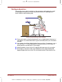
Seating and posture............................................................................3-3
Lighting ...............................................................................................3-4
Work habits.........................................................................................3-4
Connecting the AC adaptor ...................................................................3-5
Opening the display ...............................................................................3-6
Turning on the power .............................................................................3-6
Turning off the power.............................................................................3-7
Restarting the computer........................................................................3-7
Restoring the preinstalled software .....................................................3-8
Restoring the complete system ..........................................................3-8
Restoring Toshiba utilities and drivers ................................................3-8
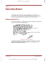
Chapter 4: Operating Basics.....................................................4-1
Using AccuPoint™ II ..............................................................................4-1
AccuPoint™ II precautions .................................................................4-2
Replacing the cap ...............................................................................4-2
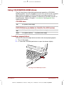
Using CD-ROM/DVD-ROM drives..........................................................4-3
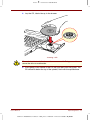
Loading compact discs .......................................................................4-3
Removing compact discs....................................................................4-6
Disk care .................................................................................................4-7
CDs.....................................................................................................4-7
Diskette Care ......................................................................................4-8
International modem ..............................................................................4-8
Country selection ................................................................................4-8
Video out ............................................................................................... 4-11
Cleaning the computer ........................................................................ 4-11
Moving the computer ........................................................................... 4-11
Heat dispersal.......................................................................................4-12
Chapter 5: The Keyboard ..........................................................5-1
Grey keys ................................................................................................5-1
F1…F12 function keys ...........................................................................5-2
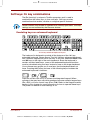
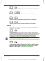
Soft Keys: Alt Gr Key Combinations ....................................................5-2
The Euro symbol.................................................................................5-2
xii
User's Manual
Satellite Pro 4200/4300 User's Manual – 4200_UK.doc – ENGLISH – Printed on 27/01/00 as IM_420UK
Version
1
Last Saved on 27/01/00 18:20
Soft keys: Fn key combinations........................................................... 5-3
Emulating keys on enhanced keyboard............................................. 5-3
Hotkeys .............................................................................................. 5-4
Windows special keys........................................................................ 5-6
Emulating Fn key on external keyboard ............................................ 5-6
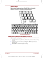
Keypad overlay ...................................................................................... 5-6
Turning on the overlays...................................................................... 5-6
Temporarily using normal keyboard (overlay on)............................... 5-7
Temporarily using overlay (overlay off) .............................................. 5-8
Temporarily changing modes ............................................................. 5-8
Generating ASCII characters ................................................................ 5-8
Chapter 6: Power and Power-Up Modes.................................. 6-1
Power conditions................................................................................... 6-1
Power indicators.................................................................................... 6-2
Battery indicators ............................................................................... 6-2
DC IN indicator................................................................................... 6-3
Power indicator .................................................................................. 6-3
Battery types .......................................................................................... 6-4
Battery pack ....................................................................................... 6-4
Real Time Clock battery..................................................................... 6-4
Care and use of the battery pack ......................................................... 6-5
Safety precautions ............................................................................. 6-5
Charging the batteries........................................................................ 6-6
Monitoring battery capacity ................................................................ 6-7
Maximising battery operating time ..................................................... 6-7
Retaining data with power off............................................................. 6-8
Extending battery life ......................................................................... 6-8
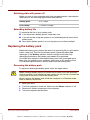
Replacing the battery pack ................................................................... 6-8
Removing the battery pack ................................................................ 6-8
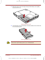
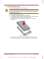
Installing the battery pack ................................................................ 6-10
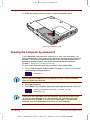
Starting the computer by password ...................................................6-11
Power-up modes.................................................................................. 6-12
Hotkeys ............................................................................................ 6-13
TSETUP ........................................................................................... 6-13
Panel power off .................................................................................... 6-13
System auto off.................................................................................... 6-13
Auto Power On..................................................................................... 6-13
Ring indicator power on...................................................................... 6-14
User's Manual
Satellite Pro 4200/4300 User's Manual – 4200_UK.doc – ENGLISH – Printed on 27/01/00 as IM_420UK
xiii
Chapter 7: Setup and Password Security................................7-1
TSETUP ...................................................................................................7-1
Executing TSETUP.............................................................................7-2
Changing values in the TSETUP menu ..............................................7-3
Accepting changes and exiting SYSTEM SETUP ..............................7-3
Default configuration...........................................................................7-3
TSETUP options .................................................................................7-4
Memory...............................................................................................7-4
Password ............................................................................................7-4
Battery ................................................................................................7-4
Hard Disk Mode ..................................................................................7-7
Password security................................................................................7-15
How to set the passwords ................................................................7-16
How to reset the passwords .............................................................7-18
Enabling TSETUP access in user password mode ..........................7-20
Making a password service diskette.................................................7-22
Chapter 8: Optional Devices .....................................................8-1
PC Cards .................................................................................................8-1
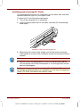
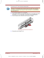
Installing a PC Card............................................................................8-2
Removing a PC Card..........................................................................8-4
Memory expansion.................................................................................8-4
Installing memory module...................................................................8-5
Removing memory module.................................................................8-6
Clearing Hibernation files ...................................................................8-7
Additional battery pack..........................................................................8-8
Battery charger.......................................................................................8-8
Card Station IV........................................................................................8-8
Front ...................................................................................................8-9
Right side............................................................................................8-9
Back..................................................................................................8-10
Left side ............................................................................................ 8-11
AC adaptor........................................................................................8-12
Connecting to the Card Station IV ....................................................8-13
Connecting the AC adaptor ..............................................................8-14
Disconnecting the Card Station IV....................................................8-14
xiv
User's Manual
Satellite Pro 4200/4300 User's Manual – 4200_UK.doc – ENGLISH – Printed on 27/01/00 as IM_420UK
Version
1
Last Saved on 27/01/00 18:20
Card Station III...................................................................................... 8-15
Front................................................................................................. 8-16
Right side ......................................................................................... 8-17
Back ................................................................................................. 8-17
Left side............................................................................................ 8-19
Spacer.............................................................................................. 8-19
Connecting to the Card Station III.................................................... 8-20
Connecting the AC adaptor.............................................................. 8-23
Installing and removing PC Cards ................................................... 8-24
Port Replicator ..................................................................................... 8-26
Front................................................................................................. 8-27
Right side ......................................................................................... 8-28
Back ................................................................................................. 8-28
Left side............................................................................................ 8-29
Connecting the Port Replicator ........................................................ 8-29
Connecting the AC adaptor.............................................................. 8-31
Disconnecting the Port Replicator.................................................... 8-31
Parallel printer...................................................................................... 8-32
External monitor .................................................................................. 8-33
PS/2 mouse .......................................................................................... 8-34
PS/2 keyboard ...................................................................................... 8-34
Security lock ........................................................................................ 8-35
Chapter 9: Troubleshooting ...................................................... 9-1
Problem solving process ...................................................................... 9-1
Preliminary checklist .......................................................................... 9-1
Analysing the problem ....................................................................... 9-2
Hardware and system checklist ........................................................... 9-3
System start-up .................................................................................. 9-3
Self test .............................................................................................. 9-3
Power ................................................................................................. 9-4
Password ........................................................................................... 9-6
Hotkeys .............................................................................................. 9-6
Keyboard............................................................................................ 9-6
LCD panel .......................................................................................... 9-7
Hard disk drive ................................................................................... 9-7
CD-ROM drive ................................................................................... 9-8
User's Manual
Satellite Pro 4200/4300 User's Manual – 4200_UK.doc – ENGLISH – Printed on 27/01/00 as IM_420UK
xv
DVD-ROM drive..................................................................................9-9
Diskette drive ....................................................................................9-10
Infrared port ......................................................................................9-10
Printer ............................................................................................... 9-11
Pointing device ................................................................................. 9-11
PC Card ............................................................................................9-13
Monitor..............................................................................................9-13
Sound system ...................................................................................9-14
USB ..................................................................................................9-14
Hibernation .......................................................................................9-15
TV output signal................................................................................9-15
Memory expansion ...........................................................................9-16
Diagnostic test......................................................................................9-17
Executing the diagnostic test program .............................................9-17
Choosing test options .......................................................................9-18
Test sequence...................................................................................9-19
Subtests............................................................................................9-19
If you need further assistance ............................................................9-25
Before you call ..................................................................................9-25
Where to write...................................................................................9-25
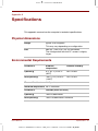
Appendix A: Specifications...................................................... A-1
Appendix B: AC Power Cord and Connectors ....................... B-1
Appendix C: The Toshiba International Warranty .................. C-1
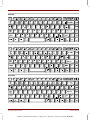
Appendix D: Keyboard Layouts .............................................. D-1
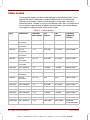
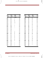
Appendix E: Display Controller and Modes ........................... E-1
Appendix F: If your computer is stolen ...................................F-1
Appendix G: ASCII Character Codes ...................................... G-1
Appendix H: International Modem Guide................................ H-1
Glossary .................................................................................... H-1
Index .......................................................................................... H-1
xvi
User's Manual
Satellite Pro 4200/4300 User's Manual – 4200_UK.doc – ENGLISH – Printed on 27/01/00 as IM_420UK
Version
1
Last Saved on 27/01/00 18:20
Preface
Congratulations on your purchase of the Satellite Pro 4200 or 4300 Series
computer. This powerful notebook computer provides excellent expansion
capability, including multimedia devices, and it is designed to provide
years of reliable, high-performance computing.
This manual tells how to set up and begin using your Satellite Pro 4200 or
4300 Series computer. It also provides detailed information on configuring
your computer, basic operations and care, using optional devices and
troubleshooting.
If you are a new user of computers or if you’re new to portable computing,
first read over the Introduction and The Grand Tour chapters to familiarise
yourself with the computer’s features, components and accessory devices.
Then read Getting Started for step-by-step instructions on setting up your
computer.
If you are an experienced computer user, please continue reading the
preface to learn how this manual is organised, then become acquainted
with this manual by browsing through its pages. Be sure to look over the
Special features section of the Introduction, to learn about features that
are uncommon or unique to the computers and carefully read Setup and
Password Security.
Manual contents
This manual is composed of 9 chapters, 8 appendices, a glossary,
and an index.
Chapter 1, Introduction, is an overview of the computer’s features,
capabilities, and options.
Chapter 2, The Grand Tour, identifies the components of the computer and
briefly explains how they function.
Chapter 3, Getting Started, provides a quick overview of how to begin
operating your computer and gives tips on safety and designing your work
area.
Chapter 4, Operating Basics, includes instructions on using the following
devices: AccuPoint™ II, CD/DVD-ROM drive and internal modem. It also
provides tips on care of the computer, diskettes and CD/DVD-ROMs.
User's Manual
Satellite Pro 4200/4300 User's Manual – 4200_UK.doc – ENGLISH – Printed on 27/01/00 as IM_420UK
xvii
Chapter 5, The Keyboard, describes special keyboard functions including
the keypad overlay and hotkeys.
Chapter 6, Power and Power-Up Modes, gives details on the computer’s
power resources and battery save modes.
Chapter 7, Setup and Password Security, explains how to configure the
computer using the TSETUP program. It also tells how to set a password.
Chapter 8, Optional Devices, describes the optional hardware available.
Chapter 9, Troubleshooting, provides helpful information on how to
perform some diagnostic tests, and suggests courses of action if the
computer doesn’t seem to be working properly.
The Appendices provide technical information about your computer.
The Glossary defines general computer terminology and includes a list of
acronyms used in the text.
The Index quickly directs you to the information contained in this manual.
Conventions
This manual uses the following formats to describe, identify, and highlight
terms and operating procedures.
Abbreviations
On first appearance, and whenever necessary for clarity, abbreviations are
enclosed in parentheses following their definition. For example: Read Only
Memory (ROM). Acronyms are also defined in the Glossary.
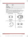
Icons
Icons identify ports, dials, and other parts of your computer. The indicator
panel also uses icons to identify the components it is providing information on.
Keys
The keyboard keys are used in the text to describe many computer
operations. A distinctive typeface identifies the key top symbols as they
appear on the keyboard. For example, Enter identifies the Enter key.
xviii
User's Manual
Satellite Pro 4200/4300 User's Manual – 4200_UK.doc – ENGLISH – Printed on 27/01/00 as IM_420UK
Version
1
Last Saved on 27/01/00 18:20
Key operation
Some operations require you to simultaneously use two or more keys. We
identify such operations by the key top symbols separated by a plus sign
(+). For example, Ctrl + C means you must hold down Ctrl and at the
same time press C. If three keys are used, hold down the first two and at
the same time press the third.
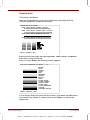
When procedures require an action such as
ABC
clicking an icon or entering text, the icon’s
name or the text you are to type in is
represented in the type face you see to the
left.
Text you are to type in is usually preceded by
the keyboard icon.
Display
ABC
Names of windows or icons or text generated
by the computer that appears on its display
screen is presented in the type face you see
to the left.
Text generated by the computer is usually
preceded by the screen icon.
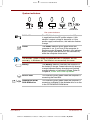
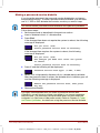
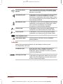
Messages
Messages are used in this manual to bring important information to your
attention. Each type of message is identified as shown below.
Pay attention! A caution informs you that improper use of equipment or
failure to follow instructions may cause data loss or damage your
equipment.
Please read. A note is a hint or advice that helps you make best use of
your equipment.
User's Manual
Satellite Pro 4200/4300 User's Manual – 4200_UK.doc – ENGLISH – Printed on 27/01/00 as IM_420UK
xix
BLANK PAGE
xx
User's Manual
Satellite Pro 4200/4300 User's Manual – 4200_UK.doc – ENGLISH – Printed on 27/01/00 as IM_420UK
Version
1
Last Saved on 27/01/00 18:20
Chapter 1
Introduction
This chapter contains an equipment checklist and identifies the computer’s
features, options and accessories.
Some of the features described in this manual may not function properly if
you use an operating system that was not preinstalled by Toshiba.
Equipment checklist
Carefully unpack your computer. Save the box and packing materials for
future use. Check to make sure you have all the following items:
Satellite Pro 4200 or 4300 Series Portable Personal Computer
Universal AC adaptor and power cord
Spare AccuPoint™ II (pointing device) caps
Modular cable (for modem)
The following software preinstalled on your hard disk:
If you have Windows 95, the following software will be retained on the
hard disk:
• Microsoft® Windows 95
• Toshiba Utilities
• Modem driver
• Display Driver for Windows
• Sound driver
• Hypertext online help
• DVD Video Player (only on models with a DVD drive)
If you have Windows 98, the following software will be retained on the
hard disk:
• Microsoft Windows 98
• The same utilities and drivers that are installed with Windows 95.
Backup CD-ROMs
• Toshiba Product Recovery CD-ROM, containing the complete
software image that came pre-installed
Toshiba Tools & Utilities CD-ROM, containing the drivers and utilities
that came pre-installed
User's Manual
Introduction 1-1
Satellite Pro 4200/4300 User's Manual – 4200_UK.doc – ENGLISH – Printed on 27/01/00 as IM_420UK
Your computer’s documentation:
• Satellite Pro 4200 or 4300 Series Personal Computer User’s Manual
• Satellite Pro 4200 or 4300 Series QuickStart
• Microsoft Windows manual package
• Safety Instruction Manual
If any of the items are missing or damaged, contact your dealer
immediately.
Features
The computer uses Toshiba’s advanced Large Scale Integration (LSI),
Complementary Metal-Oxide Semiconductor (CMOS) technology
extensively to provide compact size, minimum weight, low power usage,
and high reliability. This computer incorporates the following features and
benefits:
Microprocessor
The computer is equipped with a Mobile
Pentium® III processor which incorporates a
math co-processor and 32 KB cache memory.
4280 Series: 500 megahertz
4320 Series: 600 megahertz featuring
SpeedStep™ technology
The 4270 Series is equipped with a Mobile Celeron
processor, which operates at 500 megahertz.
1-2 Introduction
Level 2 cache
A 256 KB level 2 cache on the Pentium
processors and a 128 KB level 2 cache on the
Celeron processors maximizes performance.
Memory
The computer comes with built-in 64 MB of
Random Access Memory (RAM). Memory can be
expanded up to 320 MB.
Video RAM
The computer provides 8 MB of RAM for
video display.
Battery pack
The computer is powered by a rechargeable
lithium-ion battery pack.
RTC battery
The computer has an internal battery that backs
up the Real Time Clock (RTC) and calendar.
User's Manual
Satellite Pro 4200/4300 User's Manual – 4200_UK.doc – ENGLISH – Printed on 27/01/00 as IM_420UK
Version
1
Last Saved on 27/01/00 18:20
Display
The computer supports high-resolution video
graphics and employs a AGP bus for superior
performance. The screen is a 13.0” DSTN screen
with 800 horizontal x 600 vertical pixels or 13.3",
14.1" or 15.0” XGA-TFT with 1024 horizontal x
768 vertical pixels. It can be set at a wide range
of viewing angles for maximum comfort and
readability. The display controller also supports
simultaneous display on the internal LCD and on
an external monitor.
Graphics controller
The graphics controller incorporates a 3D graphics
accelerator to maximize video performance and
enable flickerless display. It also enables display of
up to 1024 x 768 pixels on the computer’s LCD
panel and up to 1600 x 1200 pixels on a highresolution external monitor.
Full Accelerated Graphics Port 2X support
features a peak bandwith of 2x the PCI bus.
AC adaptor
The universal AC adaptor provides power to the
system and recharges the batteries. It comes
with a detachable power cord.
Because it is universal, it can receive a range of
AC voltage from 100 to 240 volts; however, the
output current varies among different models.
Using the wrong model can damage your
computer. See the AC adaptor section in
Chapter 2, The Grand Tour.
Keyboard
An easy-to-use 85-key (United States) or 86-key
(Europe) keyboard provides a numeric keypad
overlay for fast numeric data entry or for cursor
and page control. It also includes two keys that
have special functions in Windows; one activates
the Start menu and the other functions as the
secondary mouse button. The computer’s
keyboard supports software that uses a 101- or
102-key enhanced keyboard. See Chapter 5, The
Keyboard, for details.
AccuPoint™ II
This pointer control stick, located in the centre of
the keyboard, provides convenient control of the
cursor without requiring desk space for a mouse.
Two additional programmable scroll buttons
provide convenient scrolling through large
documents or web sites
User's Manual
Introduction 1-3
Satellite Pro 4200/4300 User's Manual – 4200_UK.doc – ENGLISH – Printed on 27/01/00 as IM_420UK
Hard disk drive
The Satellite Pro 4270 or 4280 Series has an
integrated 6.0 gigabyte* , 2 ½" hard disk drive
(HDD) for nonvolatile storage of data and
software.
The Satellite Pro 4320 Series has an integrated
12 gigabyte*, 2 ½" hard disk drive (HDD) for
nonvolatile storage of data and software.
Other hard disk drive sizes may be available in
the future.
* One gigabyte means one billion byte
Diskette drive
A 3 ½" diskette drive accommodates both
1.44 MB double-sided, high-density, double-track
(2HD) and 720 KB double-sided, double-density,
double-track (2DD) disks.
CD-ROM drive
A full-size, maximum 24-speed CD-ROM drive
lets you run either 12 cm (4.72") or 8 cm (3.15")
compact discs without using an adaptor. The
computer is configured with either a CD-ROM
drive or a DVD-ROM drive. This drive supports
the following formats:
• CD-Extra
• Audio CD
• CDR (Read Only)
• Photo CD™
• CD-Rewritable
• ISO 9660
(Read Only)
A full-size, DVD-ROM drive module lets you run
DVD-ROM drive
(available for Satellite either 12 cm (4.72") or 8 cm (3.15") digital video
disk/compact disks without using an adaptor. The
Pro 4320 Series)
drive is configured with Regional Playback
Control 2 (RPC2). The drive runs DVD-ROMs at
maximum 6 speed and CD-ROMs at maximum
24 speed. The computer is configured with either
a CD-ROM drive or a DVD-ROM drive.
This drive supports the same formats as the
CD-ROM drive plus the following:
• DVD-ROM
• DVD-Video
1-4 Introduction
User's Manual
Satellite Pro 4200/4300 User's Manual – 4200_UK.doc – ENGLISH – Printed on 27/01/00 as IM_420UK
Version
User's Manual
1
Last Saved on 27/01/00 18:20
Sound system
A Sound Blaster™ Pro™ and Windows Sound
System (WSS) compatible sound system gives
your computer multimedia capability. It
incorporates a 64-channel Wave Table
Synthesizer and hardware acceleration for
advanced sound applications including 3D
games, DVD movie playback and Internet
communications. The sound system is equipped
with stereo speakers, a volume control knob and
jacks for microphone and headphone.
Microphone port
Enables connection of a microphone for
audio input.
Headphone port
Enables connection of a stereo headphone for
audio output.
Parallel port
A Centronics®-compatible parallel interface port
lets you connect a parallel printer or other parallel
device. This port supports the Extended
Capabilities Port (ECP) standard.
Serial port
A standard, 9-pin, serial port lets you connect
such serial devices as a serial printer, , bar code
reader, or Optical Character Reader (OCR). This
port supports 16550 Universal Asynchronous
Receiver/Transmitter (UART) compliant highspeed data transfer.
External monitor port
The female, 15-pin, D-shell connector lets you
connect to an external video display, which is
recognized automatically. It supports Video
Electronic Standards Association (VESA) Display
Data Channel (DDC) 2B compatible functions.
Universal Serial
Bus port
A Universal Serial Bus (USB) port enables chain
connection of a number of USB-equipped
devices to one port on your computer. For
example, you might connect a USB-HUB to the
computer, then connect a keyboard to the USBHUB and a mouse to the keyboard. Use the USB
drivers that come with external USB devices. If
your operating system does not support USB,
you can still use a USB mouse and keyboard by
setting the USB Legacy item in TSETUP to
Enabled. Refer to Chapter 7, Setup and
Password Security, for details.
Introduction 1-5
Satellite Pro 4200/4300 User's Manual – 4200_UK.doc – ENGLISH – Printed on 27/01/00 as IM_420UK
1-6 Introduction
PS/2™ mouse/
keyboard port
This port lets you connect a PS/2 mouse or
PS/2 keyboard to the computer.
PC card slots
A PC Card Slot accommodates two 5 mm cards
(Type II) or one 10.5 mm (Type III) card. These slots
support 16-bit PC Cards and CardBus PC Cards
(32 bit). For more information, refer to the PC Card
section in Chapter 8, Optional Devices.
Video out
This RCA video jack lets you transfer NTSC or
PAL data to external devices.
Memory expansion
socket
Two sockets are available for installation of 32,
64 or 128 MB memory modules.
International modem
A built-in modem provides capability for data and
fax communication and supports ITU-T V.90 and
K56 flex. It operates at 56,000 bps (maximum) for
data transfer and at 14,400 bps (maximum) for
fax. The speed of data transfer and fax depends
on analog telephone line conditions. It has a RJ11 modem jack for connecting to a telephone
line.
Infrared port
An infrared port on the back of the computer
enables use of Infrared Data Association (IrDA)
devices. The infrared port is compatible with Fast
InfraRed (FIR) standards enabling cableless
4 Mbps data transfer with IrDA 1.1 compatible
external devices.
Plug and Play
When you connect an external device to the
computer, Plug and Play capability enables the
system to recognize the connection and make
the necessary configurations automatically. This
feature is effective only with Windows 98/95.
User's Manual
Satellite Pro 4200/4300 User's Manual – 4200_UK.doc – ENGLISH – Printed on 27/01/00 as IM_420UK
Version
1
Last Saved on 27/01/00 18:20
Special features
The following features are either unique to Toshiba computers or are
advanced features, which make the computer more convenient to use.
User's Manual
Hotkeys
Key combinations let you quickly modify the
system configuration directly from the keyboard
without running a system configuration program.
Display automatic
power off
This feature automatically cuts off power to the
internal display when there is no keyboard input
for a time specified. Power is restored when any
key is pressed. If you use Windows 95, you can
specify the time in the Display Auto Off window of
Power Save Modes in Power Saver. If you use
Windows 98, you can specify the time in the Turn
off monitor item of the Power Save Mode window
of Power Saver.
HDD automatic
power off
This feature automatically cuts off power to the
hard disk drive when it is not accessed for a time
specified. Power is restored when the hard disk is
accessed. If you use Windows 95, you can
specify the time in the HDD Auto Off window of
Power Save Modes in Power Saver. If you use
Windows 98, you can specify the time in the Turn
off hard disks item of the Power Save Mode
window of Power Saver.
System automatic
power off
This feature automatically turns off power to the
system when there is no activity for a period of
time specified. If you use Windows 95, you can
specify the time in the System window of Power
Save Modes in Power Saver. If you use
Windows 98, you can specify the time in the
System standby item of the Power Save Mode
window of Power Saver.
Keypad overlay
Dark grey keys with grey lettering make up the
keypad overlay, which lets you use the keyboard
for ten-key operations or cursor control.
Intelligent power
supply
A microprocessor in the computer’s intelligent
power supply detects the battery’s charge and
calculates the remaining battery capacity. It also
protects electronic components from abnormal
conditions, such as voltage overload from an
AC adaptor.
Introduction 1-7
Satellite Pro 4200/4300 User's Manual – 4200_UK.doc – ENGLISH – Printed on 27/01/00 as IM_420UK
1-8 Introduction
Battery save mode
This feature lets you save battery power. If you
use Windows 95, you can specify the Power
Save Mode in the Power Save Modes window in
Power Saver. If you use Windows 98, you can
specify the Power Save Mode in the Running on
batteries item of the Power Save Modes window
in Power Saver.
Power on password
Two levels of password security are available:
supervisor and user. This feature prevents
unauthorized access to your computer.
Instant security
A hotkey function blanks the screen and disables
the computer providing for quick and easy data
security.
Panel power on/off
This feature turns power to the computer off
when the display panel is closed and turns it back
on when the panel is opened. If you use
Windows 95, you can specify the setting in the
System window of Power Save Modes in Power
Saver. If you use Windows 98, you can specify
the setting in the When I close the lid item of the
System Power Mode window of the Power Save
Modes in Power Saver.
Low battery
automatic suspend
When battery power is exhausted to the point
that computer operation cannot be continued, the
system automatically enters Hibernation and
shuts down.
Auto power on
This feature lets you set a time and date for the
computer to turn on automatically. The feature is
useful for receiving remote communications while
you are asleep or away. If you use Windows 95,
you can specify the time in the Auto Power On
window in Power Saver. If you use Windows 98,
you can specify the time in Scheduled Tasks.
Ring indicator
power on
This feature lets the computer’s power be turned
on automatically when a call comes in from a
remote modem. When the computer’s internal
modem or an external modem connected to the
computer’s serial port receives a call from a
remote modem, it sends a ring indicator power on
signal to the computer. This features also works
with a PC Card modem in Windows 98. It works
only in Resume (Suspend or Standby) mode.
User's Manual
Satellite Pro 4200/4300 User's Manual – 4200_UK.doc – ENGLISH – Printed on 27/01/00 as IM_420UK
Version
1
Last Saved on 27/01/00 18:20
Heat dispersal
To protect from overheating, the CPU has an internal
temperature sensor. If the computer’s internal
temperature rises to a certain level, the cooling fan is
turned on or the processing speed is lowered. To
make one of the three temperature control settings in
Windows 95, use the System window of Power Save
Modes in Power Saver. In Windows 98, use Fan
window in Power Save Modes.
• Maximum
Turns on fan first, then if
performance
necessary lowers CPU
(Windows 95)
processing speed.
Auto 1
(Windows 98)
• Performance
Uses a combination of fan
(Windows 95)
and lowering the CPU
Auto 1
processing speed.
(Windows 98)
• Battery
Lowers the CPU processing
optimized
speed first, then if
(Windows 95)
necessary turns on the fan.
Auto 1
(Windows 98)
Hibernation
This feature lets you turn off the power without
exiting from your software. The contents of main
memory is saved to the hard disk, when you turn
on the power again, you can continue working
right where you left off.
You cannot use Hibernation under the following conditions:
You are using Drive Space for Drive C or other compression utility.
You are using Windows 98 drive converter to convert files to the File
Allocation Table 32 format.
Resume
(Suspend, Standby)
If you have to interrupt your work, you can turn
off the power without exiting from your software.
Data is maintained in the computer’s main
memory. When you turn on the power again, you
can continue working right where you left off.
The Resume mode is called Suspend/Resume in Windows 95 and
Standby in Windows 98. The functions are essentially the same.
Do not remove the battery pack while the computer is in Resume mode.
Data in memory will be lost.
User's Manual
Introduction 1-9
Satellite Pro 4200/4300 User's Manual – 4200_UK.doc – ENGLISH – Printed on 27/01/00 as IM_420UK
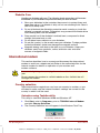
Utilities
This section describes preinstalled utilities and tells how to start them. For
details on operations, refer to each utility’s online manual, help files or
read.me files.
1-10 Introduction
Power Saver Utility
To access this power savings management
program, open the Control Panel and doubleclick the Power Saver icon.
Hardware setup
This program lets you customize your hardware
settings according to the way you work with your
computer and the peripherals you use. To start
the utility, click the Windows Start button, point
to settings and click Control Panel. In the
Control Panel, double-click the Toshiba
Hardware Setup icon.
TSETUP
An easy-to-use menu lets you customize the
configuration of your computer in a DOS
environment according to the way you work with
your computer and the peripherals you use. Refer
to Chapter 7, Setup and Password Security.
DVD Video Player
(DVD models only)
The DVD Video Player is used to play
DVD Movies. It has an on-screen interface and
functions similar to those of a standard
DVD player. Click Start, point to Programs, point
to Mediamatics DVD Express, then click
Mediamatics DVD Player.
User's Manual
Satellite Pro 4200/4300 User's Manual – 4200_UK.doc – ENGLISH – Printed on 27/01/00 as IM_420UK
Version
1
Last Saved on 27/01/00 18:20
Options
You can add a number of options to make your computer even more
powerful and convenient to use. The following options are available:
User's Manual
Memory expansion
A 32, 64, 128 or 256 MB memory module can be
installed in the computer.
Battery pack
An additional battery pack can be purchased
from your Toshiba dealer. Use it as a spare to
increase your computer operating time.
AC adaptor
If you use your computer at more than one site
frequently, it may be convenient to purchase an
additional AC adaptor for each site so you will not
have to carry the adaptor with you.
Battery charger
A battery charger lets you charge extra batteries
outside the computer.
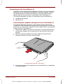
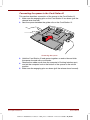
Card Station III
The Card Station III provides the ports available on
the computer, in addition to MIDI/Joystick, audio
line-out and separate PS/2 and PS/2 keyboard
ports. It also has two USB ports and two additional
PC Card Slots that each accommodate a 5 mm
(Type II) or a 10.5 mm (Type III) card. A spacer is
required to connect the computer to a Card
Station III. However, Card Station III is not
compatible with the Satellite Pro 4320.
Card Station IV
The Card Station IV provides the ports available
on the computer, in addition to audio line-in and
line-out jacks and separate ports for PS/2 mouse
and PS/2 keyboard, two USB ports and one PC
Card Slot (Type III) that can be used in addition
to the slots on the computer. Please use only the
60 watts AC adaptor in combination with Satellite
Pro 4320.
Spacer
Connect the computer to an optional spacer for
connection to Card Station III.
Port Replicator
The Port Replicator provides the ports available on
the computer, in addition to MIDI/Joystick, audio
line-in and line-out and separate PS/2 mouse and
PS/2 keyboard ports. It also has two USB ports.
Keytop sets
You can customize your keyboard for a variety of
languages by replacing the keytops.
Security lock
A slot is available to attach a security cable to the
computer to deter theft.
Introduction 1-11
Satellite Pro 4200/4300 User's Manual – 4200_UK.doc – ENGLISH – Printed on 27/01/00 as IM_420UK
BLANK PAGE
1-12 Introduction
User's Manual
Satellite Pro 4200/4300 User's Manual – 4200_UK.doc – ENGLISH – Printed on 27/01/00 as IM_420UK
1
Version
Last Saved on 27/01/00 18:20
Chapter 2
The Grand Tour
This chapter identifies the various components of your computer. Become
familiar with each component before you operate the computer.
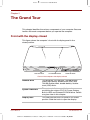
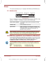
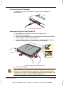
Front with the display closed
This figure shows the computer’s front with its display panel in the
closed position.
DISPLAY LATCH
SYSTEM INDICATORS
DISKETTE DRIVE
Front of the computer with display closed
User's Manual
Diskette drive
This drive lets you use both 1.44 MB doublesided, high-density, double-track (2HD) and
720 KB double-sided, double-density, doubletrack (2DD) disks.
System indicators
The system indicators provide icons for
monitoring the status of DC IN, Power, Battery,
Built-in HDD and Diskette/CD-ROM drive. Details
are given later in this chapter.
Display latch
This latch secures the LCD panel in its closed
position. Slide the latch to open the display.
The Grand Tour 2-1
Satellite Pro 4200/4300 User's Manual – 4200_UK.doc – ENGLISH – Printed on 27/01/00 as IM_420UK
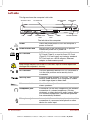
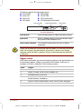
Left side
This figure shows the computer’s left side.
SECURITY LOCK
FAN
PC CARD SLOT
POWER
POWER BUTTON
LOCK
MICROPHONE
JACK
PC CARD
LOCK
RESET
HEADPHONE
JACK
VOLUME CONTROL
The left side of the computer
Power
Press the power button to turn the computer’s
power on and off.
Power button lock
Set this lock to the locked position to prevent
inadvertent power on or power off.
PC Card slot
A PC Card slot can accommodate two 5 mm
PC Cards (Type II) or one 10.5 mm PC Card
(Type III). You can install any industry standard
PC Card such as a SCSI adaptor, Ethernet
adaptor or flash memory card.
Keep foreign objects out of the PC Card slot. A pin or similar object can
damage the computer’s circuitry.
PC Card lock
This lock prevents removal of a PC Card when it
is in the lock position and a security lock is
connected.
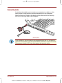
Security lock
A security cable attaches to this slot. The optional
security cable anchors your computer to a desk
or other large object to deter theft.
Volume control
Use this dial to adjust the volume of the
stereo speakers.
Headphone jack
A standard 3.5 mm mini headphone jack enables
connection of a stereo headphone (16 ohm
minimum) or other device for audio output. When
you connect headphones, the internal speakers
are automatically disabled.
Microphone jack
A standard 3.5 mm mini microphone jack enables
connection of a monaural microphone or other
device for audio input.
2-2 The Grand Tour
User's Manual
Satellite Pro 4200/4300 User's Manual – 4200_UK.doc – ENGLISH – Printed on 27/01/00 as IM_420UK
Version
Reset
1
Last Saved on 27/01/00 18:20
Press the reset button to reset the computer when it
does not respond to keyboard commands. Use a
narrow object such as the tip of a covered ball-point
pen. The system restarts, clearing all data in
memory and overriding the Resume feature. See
Chapter 6, Power and Power-Up Modes, for more
information on the switch and Resume.
Do not use a pencil to push the reset button. Pencil lead can break off
inside the computer and damage its circuitry.
Fan
A fan keeps the CPU from overheating.
Be careful not to block the fan vent. Also be careful to keep foreign objects out
of it. A pin or similar object can damage the computer’s circuitry.
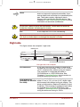
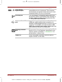
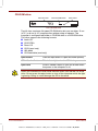
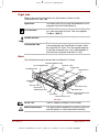
Right side
This figure shows the computer’s right side.
MODEM JACK
CD-ROM OR DVD-ROM DRIVE
The right side of the computer
CD-ROM drive
A full-size, maximum 24-speed CD-ROM drive
module lets you run either 12 cm (4.72") or 8 cm
(3.15") compact disks without using an adaptor.
The computer is configured with either a
CD-ROM drive or a DVD-ROM drive. See
Chapter 4, Operating Basics, for information on
using the drive and caring for CDs.
A full-size DVD-ROM drive module lets you run
DVD-ROM drive
(available for Satellite either 12 cm (4.72") or 8 cm (3.15") digital video
disk/compact disk without using an adaptor. The
Pro 4320)
drive is configured as Regional Playback Control
2 (RPC2). The computer is configured with either
a CD-ROM drive or a DVD-ROM drive. See
Chapter 4, Operating Basics, for information on
using the drive and caring for DVDs.
User's Manual
The Grand Tour 2-3
Satellite Pro 4200/4300 User's Manual – 4200_UK.doc – ENGLISH – Printed on 27/01/00 as IM_420UK
Modem jack
A RJ-11 modem jack lets you use a modular
cable to connect the modem directly to a
telephone line.
In case of a lighting storm, unplug the modem cable from the
telephone jack.
Do not connect the modem to a digital telephone line. A digital line will
damage the modem.
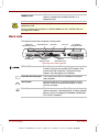
Back side
This figure shows the computer’s back panel.
VIDEO OUT
(DVD MODELS ONLY)
SERIAL PORT
INFRARED PORT
EXTERNAL
MONITOR PORT
USB PORT
DC IN 15V
DOCKING
INTERFACE PORT
PS/2 MOUSE/
KEYBOARD PORT
PARALLEL PORT
The back side of the computer
DC IN 15V
DC IN 15V
The AC adaptor’s DC output plug connects to this
socket. Use only the model of AC adaptor that
comes with the computer. Using the wrong
adaptor can damage your computer.
External monitor port This 15-pin port lets you connect an external
video display.
Serial port
Use this 9-pin port to connect external serial
devices such as an external modem, a serial
mouse or printer.
Parallel port
This Centronics-compatible 25-pin parallel port is
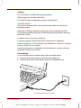
used to connect a parallel printer or other parallel
device. This port supports Extended Capabilities
Port (ECP) standard.
2-4 The Grand Tour
User's Manual
Satellite Pro 4200/4300 User's Manual – 4200_UK.doc – ENGLISH – Printed on 27/01/00 as IM_420UK
Version
User's Manual
1
Last Saved on 27/01/00 18:20
PS/2 mouse/
keyboard port
Use this port to connect an external PS/2
compatible mouse or keyboard. The computer
automatically recognizes which device you have
connected when you turn on the power.
Infrared port
This infrared port is compatible with Infrared Data
Association (IrDA) Fast InfraRed (FIR) standards. It
enables cableless 4 Mbps data transfer with IrDA
1.1 compatible external devices.
Universal Serial Bus
port
A plastic cover protects the Universal Serial Bus
(USB) port, which enables chain connection of a
number of USB-equipped devices to one port on your
computer. For example, you might connect a USBHUB to the computer, then connect a keyboard to the
USB-HUB and a mouse to the keyboard.
Docking interface
port
This port enables connection of an optional Card
Station III/IV or Port Replicator described in the
Options section of Chapter 1, Introduction. It is
protected by a rubber cover.
Video out
Plug a RCA video connector into this jack for
output of NTSC or PAL data.
The Grand Tour 2-5
Satellite Pro 4200/4300 User's Manual – 4200_UK.doc – ENGLISH – Printed on 27/01/00 as IM_420UK
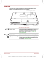
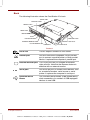
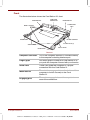
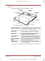
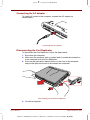
Underside
This illustration shows the underside of the computer. Make sure the
display is closed before turning over your computer.
EXPANSION MEMORY SOCKET
BATTERY COVER
BATTERY LATCH
The underside of the computer
Battery cover
This cover protects the battery pack, which
powers the computer when the AC adaptor is not
connected. For detailed information on the
battery pack, refer to Chapter 6, Power and
Power-Up Modes.
Battery latch
Slide this latch open to remove the battery pack.
Expansion memory
sockets
Use these sockets to install a memory module to
increase your computer’s memory by 32, 64 or
128 MB. Refer to the Memory expansion section
in Chapter 8, Optional Devices.
2-6 The Grand Tour
User's Manual
Satellite Pro 4200/4300 User's Manual – 4200_UK.doc – ENGLISH – Printed on 27/01/00 as IM_420UK
Version
1
Last Saved on 27/01/00 18:20
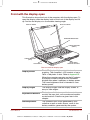
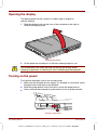
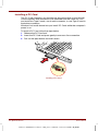
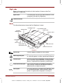
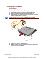
Front with the display open
This illustration shows the front of the computer with the display open. To
open the display, slide the display latch on the front of the display and lift
up. Position the display at a comfortable viewing angle.
DISPLAY SCREEN
DISPLAY HINGES
KEYBOARD INDICATORS
STEREO SPEAKER
(RIGHT)
STEREO SPEAKER
(LEFT)
ACCUPOINT II
CONTROL BUTTONS
ACCUPOINT II
The front with the display open
Display screen
The LCD displays high-contrast text and
graphics. The computer’s LCD consists of up to
1024 x 768 pixels or dots. Refer to Appendix E.
When the computer operates on the AC adaptor
the display screen’s image will be somewhat
brighter than when it operates on battery power.
The lower brightness level is intended to save
battery power.
User's Manual
Display hinges
The display hinges hold the display screen at
easy-to-view angles.
Keyboard indicators
The keyboard indicators provide icons to let you
monitor the caps lock, arrow mode and numeric
mode functions. Details are given later in this
chapter.
Stereo speakers
The speakers emit sound generated by your
software as well as audio alarms, such as low
battery condition, generated by the system.
The Grand Tour 2-7
Satellite Pro 4200/4300 User's Manual – 4200_UK.doc – ENGLISH – Printed on 27/01/00 as IM_420UK
AccuPoint™ II
A pointer control device located in the centre of
the keyboard is used to control the on-screen
pointer. Refer to the Using AccuPoint™ II section
in Chapter 4, Operating Basics.
AccuPoint™ II
control buttons
Control buttons below the keyboard let you select
menu items or manipulate text and graphics
designated by the on-screen pointer.
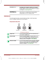
Indicators
The following illustrations show the indicator lights, which light when
various computer operations are in progress.
Keyboard indicators
CAPS LOCK
ARROW MODE
NUMERIC MODE
The keyboard indicators
Caps Lock
This icon glows green when the alphabet keys
are locked in uppercase.
Arrow mode
When the Arrow mode icon lights green, you
can use the keypad overlay (light grey labelled
keys) as cursor keys. Refer to the Keypad
overlay section in Chapter 5, The Keyboard.
Numeric mode
You can use the keypad overlay (light grey labelled
keys) for numeric input when the Numeric mode
icon lights green. Refer to the Keypad overlay
section in Chapter 5, The Keyboard.
2-8 The Grand Tour
User's Manual
Satellite Pro 4200/4300 User's Manual – 4200_UK.doc – ENGLISH – Printed on 27/01/00 as IM_420UK
Version
1
Last Saved on 27/01/00 18:20
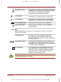
System indicators
DC IN 15V
POWER
BATTERY
BUILT-IN HDD
DISKETTE/
CD-ROM DRIVE
The system indicators
DC IN 15V
The DC IN indicator glows green when DC power
is supplied from the AC power adaptor. If the
adaptor’s output voltage is abnormal or if the
power supply malfunctions, this indicator flashes
orange.
Power
The Power indicator glows green when the
computer is on. If you turn off the computer in
Resume mode (Suspend, Standby), this indicator
blinks orange (one second on, two seconds off)
while the computer shuts down.
The Resume mode is called Suspend/Resume in Windows 95 and
Standby in Windows 98. The functions are essentially the same.
User's Manual
Battery
The Battery indicator indicates the condition of
the battery’s charge: Green indicates full charge,
orange indicates battery charging and flashing
orange indicates a low battery charge. Refer to
Chapter 6, Power and Power-Up Modes.
Built-in HDD
This indicator glows green when the computer is
accessing the hard disk.
Diskette/CD-ROM/
DVD-ROM drive
This indicator glows green when the computer is
accessing a diskette in the diskette drive or a disc
in the CD-ROM/DVD-ROM drive.
The Grand Tour 2-9
Satellite Pro 4200/4300 User's Manual – 4200_UK.doc – ENGLISH – Printed on 27/01/00 as IM_420UK
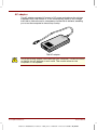
Drives
This section describes the 3 ½" diskette, DVD-ROM and CD-ROM drives.
3 ½" diskette drive
DISK-IN-USE INDICATOR
DISKETTE SLOT
EJECT BUTTON
The diskette drive
The 3 ½" diskette drive lets you use either double density (720 KB) or high
density (1.44 MB) 3 ½" diskettes for data transfer and storage.
Disk-In-Use Indicator
This indicator lights when the diskette is being
accessed.
Diskette slot
Insert diskettes in this slot.
Eject button
When a diskette is fully seated in the drive, the
eject button pops out. To remove a diskette, push
in the eject button and the diskette pops out
partially for easy removal.
Check the disk-in-use indicator when you use the diskette drive. Do not
press the eject button or turn off the computer while the light is glowing.
Doing so could destroy data and damage the diskette or the drive.
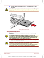
DVD-ROM drive (available for some Satellite Pro 4320 Series)
A full-size DVD-ROM drive module lets you run either 12 cm (4.72") or 8 cm
(3.15") digital video disk/compact disk without using an adaptor. The drive is
configured as Regional Playback Control 2 (RPC2). The computer is
configured with either a CD-ROM drive or a DVD-ROM drive.
The read speed is slower at the centre of a disk and faster at the outer
edge. The minimum (centre) and maximum (outer edge) for DVDs and
CDs are:
DVD
2.5-speed (centre)
6-speed (outer edge)
CD
10.3-speed (centre)
24-speed (outer edge)
2-10 The Grand Tour
User's Manual
Satellite Pro 4200/4300 User's Manual – 4200_UK.doc – ENGLISH – Printed on 27/01/00 as IM_420UK
Version
1
Last Saved on 27/01/00 18:20
This drive supports the following formats:
DVD-ROM
DVD-Video
Audio CD
CD-EXTRA
Photo CD
CD-R (read only)
ISO 9660
CD-Rewritable (read only)
EJECT BUTTON
CD-IN-USE INDICATOR
EJECT HOLE
The DVD-ROM drive
Eject button
Press the eject button to open the drawer partially.
Eject hole
Insert a slender object to open the drawer when
the power to the computer is off.
DVD-In-Use Indicator
This indicator lights when the DVD is being
accessed.
Check the Diskette/CD-ROM Drive indicator when you use the DVD-ROM
drive. Do not press the eject button, disconnect a drive or turn off the
computer while the light is glowing. Doing so could damage the DVD/CD
or the drive.
Region codes
DVD drives and media are manufactured according to the specifications of
six marketing regions. When you purchase DVD media, make sure it
matches your drive, otherwise it will not play properly.
User's Manual
Code
Region
1
Canada, United States
2
Japan, Europe, South Africa, Middle East
3
Southeast Asia, East Asia
4
Australia, New Zealand, Pacific Islands, Central America,
South America, Caribbean
5
Russia, Indian Subcontinent, Africa, North Korea, Mongolia
6
China
The Grand Tour 2-11
Satellite Pro 4200/4300 User's Manual – 4200_UK.doc – ENGLISH – Printed on 27/01/00 as IM_420UK
CD-ROM drive
EJECT BUTTON
CD-IN-USE INDICATOR
EJECT HOLE
The CD-ROM drive
The full-size, maximum 24-speed CD-ROM drive lets you run either 12 cm
(4.72") or 8 cm (3.15") compact discs without using an adaptor. The
computer is configured with either a CD-ROM drive or a DVD-ROM drive.
This drive supports the following formats:
Audio CD
CD-EXTRA
Photo CD
CD-R (read only)
ISO 9660
CD-Rewritable (read only)
Eject button
Press the eject button to open the drawer partially.
CD-In-Use Indicator
This indicator lights when the CD is being accessed.
Eject hole
Insert a slender object to open the drawer when
the power to the computer is off.
Check the Diskette/CD-ROM Drive indicator when you use the CD-ROM
drive. Do not press the eject button or turn off the computer while the light
is glowing. Doing so could damage the CD or the drive.
2-12 The Grand Tour
User's Manual
Satellite Pro 4200/4300 User's Manual – 4200_UK.doc – ENGLISH – Printed on 27/01/00 as IM_420UK
Version
1
Last Saved on 27/01/00 18:20
AC adaptor
The AC adaptor converts AC power to DC power and reduces the voltage
supplied to the computer. It can automatically adjust to any voltage from
100 to 240 volts and to a frequency of either 50 or 60 hertz, enabling you
to use the computer in almost any country.
To recharge the battery, simply connect the AC adaptor to a power source
and the computer. See Chapter 6, Power and Power-Up Modes, for
details.
TO
SH
IBA
The AC adaptor
Use of the wrong adaptor could damage your computer. Toshiba assumes
no liability for any damage in such case. The current ratings are:
Satellite Pro 4300 series
60W, 15V DC, 4 Amperes
All other models
45W, 15V DC, 3 Amperes
User's Manual
The Grand Tour 2-13
Satellite Pro 4200/4300 User's Manual – 4200_UK.doc – ENGLISH – Printed on 27/01/00 as IM_420UK
BLANK PAGE
2-14 The Grand Tour
User's Manual
Satellite Pro 4200/4300 User's Manual – 4200_UK.doc – ENGLISH – Printed on 27/01/00 as IM_420UK
Version
1
Last Saved on 27/01/00 18:20
Chapter 3
Getting Started
This chapter provides basic information to get you started using your
computer. It covers the following topics:
Setting up your work space — for your health and safety
Connecting the AC adaptor
Opening the display
Turning on the power
Turning off the power
Restarting the computer
Restoring the preinstalled software
Setting up
Establishing a comfortable work site is important for you and your
computer. A poor work environment or stressful work habits can result in
discomfort or serious injury from repetitive strain to your hands, wrists or
other joints. Proper ambient conditions should also be maintained for the
computer’s operation. This section discusses the following topics:
General conditions
Placement of the computer and peripheral devices
Seating and posture
Lighting
Work habits
User's Manual
Getting Started 3-1
Satellite Pro 4200/4300 User's Manual – 4200_UK.doc – ENGLISH – Printed on 27/01/00 as IM_420UK
General conditions
In general, if you are comfortable, so is your computer, but read the
following to make sure your work site provides a proper environment.
Make sure there is adequate space around the computer for proper
ventilation.
Make sure the AC power cord connects to an outlet that is close to the
computer and easily accessible.
The temperature should be 5 to 35 degrees Centigrade (41 to
95 degrees Fahrenheit) and the relative humidity should be 20 to
80 percent.
Avoid areas where rapid or extreme changes in temperature or
humidity may occur.
Keep the computer free of dust, moisture, and exposure to direct sunlight.
Keep the computer away from heat sources, such as electric heaters.
Do not use the computer near liquids or corrosive chemicals.
Do not place the computer near objects that create strong magnetic
fields (e.g., stereo speakers).
Do not operate the computer in close proximity to a mobile phone.
Leave ample ventilation room for the fan. Do not block the vents.
Placement of computer
Position the computer and peripheral devices to provide comfort and safety.
Set the computer on a flat surface at a comfortable height and distance.
The display should be no higher than eye level to avoid eye strain.
Place the computer so that it is directly in front of you when you work
and make sure you have adequate space to easily operate other
devices.
Allow adequate space behind the computer to let you freely adjust the
display. The display should be angled to reduce glare and maximize
visibility.
If you use a paper holder, set it at about the same height and distance
as the computer.
3-2 Getting Started
User's Manual
Satellite Pro 4200/4300 User's Manual – 4200_UK.doc – ENGLISH – Printed on 27/01/00 as IM_420UK
1
Version
Last Saved on 27/01/00 18:20
Seating and posture
The height of your chair in relation to the computer and keyboard as well
as the support it gives your body are primary factors in reducing work
strain. Refer to the following tips.
1
Posture and positioning of the computer
Place your chair so that the keyboard is at or slightly below the level of
your elbow. You should be able to type comfortably with your shoulders
relaxed.
Your knees should be slightly higher than your hips. If necessary, use a
foot rest (see "1" in the illustration) to raise the level of your knees to
ease pressure on the back of your thighs.
Adjust the back of your chair so it supports the lower curve of your spine.
Sit straight so that your knees, hips and elbows form approximately 90
degree angles when you work. Do not slump forward or lean back too far.
User's Manual
Getting Started 3-3
Satellite Pro 4200/4300 User's Manual – 4200_UK.doc – ENGLISH – Printed on 27/01/00 as IM_420UK
Lighting
Proper lighting can improve legibility of the display and reduce eye strain.
Position the computer so that sunlight or bright indoor lighting does not
reflect off the screen. Use tinted windows, shades or other screen to
eliminate sun glare.
Avoid placing the computer in front of bright light that could shine
directly in your eyes.
If possible, use soft, indirect lighting in your computer work area. Use a
lamp to illuminate your documents or desk, but be sure to position the
lamp so that it does not reflect off the display or shine in your eyes.
Work habits
A key to avoiding discomfort or injury from repetitive strain is to vary your
activities. If possible, schedule a variety of tasks into your work day. If you
must spend long periods at the computer, finding ways to break up the
routine can reduce stress and improve your efficiency.
Sit in a relaxed posture. Good positioning of your chair and equipment
as described earlier can reduce tension in your shoulders or neck and
ease back strain.
Vary your posture frequently.
Occasionally stand up and stretch or exercise briefly.
Exercise and stretch your wrists and hands a number of times during
the day.
Frequently, look away from the computer and focus your eyes on a
distant object for several seconds, for example 30 seconds every
15 minutes.
Take frequent short breaks instead of one or two long breaks, for
example, two or three minutes every half hour.
Have your eyes examined regularly and visit a doctor promptly, if you
suspect you might be suffering from a repetitive strain injury.
A number of books are available on ergonomics and repetitive strain injury
or repetitive stress syndrome. For more information on these topics or for
pointers on exercises for such stress points as hands and wrists, please
check with your library or book vendor. Also refer to the computer’s Safety
Instruction Manual.
3-4 Getting Started
User's Manual
Satellite Pro 4200/4300 User's Manual – 4200_UK.doc – ENGLISH – Printed on 27/01/00 as IM_420UK
Version
1
Last Saved on 27/01/00 18:20
Connecting the AC adaptor
Attach the AC adaptor when you need to charge the battery or you want to
operate from AC power. It is also the fastest way to get started, because
the battery pack will need to be charged before you can operate from
battery power.
The AC adaptor can be connected to any power source supplying from 100 to
240 volts and 50 or 60 hertz. For details on using the AC adaptor to charge the
battery pack, refer to Chapter 6, Power and Power-Up Modes.
Use of the wrong adaptor could damage your computer. Toshiba assumes
no liability for any damage in such case. The current rating for the
computer is 3.0 amperes.
1. Connect the power cord to the AC adaptor.
Connecting the power cord to the AC adaptor
2. Connect the AC adaptor’s DC output plug to the DC IN input port on
the back of the computer.
Connecting the adaptor to the computer
3. Plug the power cord into a live wall outlet. The Battery and DC IN
indicators on the front of the computer should glow.
User's Manual
Getting Started 3-5
Satellite Pro 4200/4300 User's Manual – 4200_UK.doc – ENGLISH – Printed on 27/01/00 as IM_420UK
Opening the display
The display panel can be rotated in a wide range of angles for
optimal viewing.
1. Slide the display latch on the front of the computer to the right to
unlatch the display panel.
Opening the display
2. Lift the panel up and adjust it to the best viewing angle for you.
Use reasonable care when opening and closing the display panel.
Opening it vigorously or slamming it shut could damage the computer.
Turning on the power
This section describes how to turn on the power.
1. Make sure the diskette drive is empty. If a diskette is in the drive, press
the eject button and remove the diskette.
2. Slide the power button lock to the left to unlock the power button.
3. Press and hold the computer’s power button for two or three seconds.
Turning on the power
3-6 Getting Started
User's Manual
Satellite Pro 4200/4300 User's Manual – 4200_UK.doc – ENGLISH – Printed on 27/01/00 as IM_420UK
Version
1
Last Saved on 27/01/00 18:20
Turning off the power
When you have finished work, follow the steps below to turn off the power
to your computer.
1. If you have entered data, save it to the hard disk or to a diskette.
2. Make sure all disk activity has stopped, then remove any CD-ROM,
DVD-ROM or diskette.
Make sure the Built-in HDD and Diskette/CD-ROM/DVD-ROM drive
indicators are off. If you turn off the power while a disk is being accessed,
you can lose data or damage the disk.
3. If you are using Windows 95, click Start then click Shut Down
or Suspend.
If you are using Windows 98, click Start and click Shut Down. From
the Shut Down menu select Shut Down or Standby.
Shut Down exits all applications; Suspend and Standby saves the
screen as it is so you can continue where you left when you turn the
power back on.
Generally, it is a good idea to use the Windows Shut Down menu rather
than the power switch to turn off the computer. However, if you are using
Windows 95, you can activate the Toshiba Service power off function to
ensure a safe shutdown when you press the power switch.
4. Turn off the power to any peripheral devices.
Do not turn the computer or devices back on immediately. Wait a moment
to let all capacitors fully discharge.
Restarting the computer
Certain conditions require that you reset the system. For example, if:
You change certain computer settings.
An error occurs and the computer does not respond to your keyboard
commands.
There are five ways to reset the computer system:
1. Select Shut Down from the Windows Shut Down menu in the Start
box. After the computer shuts down, turn the power back on.
2. Select Restart from the Windows Shut Down menu in the Start box.
3. Press Ctrl + Alt + Del.
4. If you’re experiencing a problem with a software application and the
computer does not accept keyboard input, press the reset button.
5. Turn the power off, wait 10 to 15 seconds, then turn the power on
again by pressing the power button. (This method works only when the
computer is in boot mode.)
User's Manual
Getting Started 3-7
Satellite Pro 4200/4300 User's Manual – 4200_UK.doc – ENGLISH – Printed on 27/01/00 as IM_420UK
Restoring the preinstalled software
If preinstalled files are damaged, use the Product Recovery CD-ROM or
the Toshiba Tools & Utilities CD-ROM to restore them.
Restoring the complete system
To restore the operating system and all preinstalled software, follow the
steps below.
When you reinstall the Windows operating system, the hard disk will be
reformatted and all data will be lost. Make sure you have a backup copy of
your data, before you perform a complete system recovery.
1. Load the Product Recovery CD-ROM in the drive and turn off the
computer’s power.
2. Hold down the C key and turn on the power. When In Touch with
Tomorrow TOSHIBA appears, release the C key.
Follow the on-screen directions to restore the preinstalled software.
3. On some computers you will be prompted to replace the Product
Recovery CD. Follow the on-screen directions.
4. After recovery is complete, remove the Product Recovery CD.
5. Press Ctrl + Alt + Del to restart the system. Refer to your Microsoft
user’s manual for Window’s setup instructions.
Restoring Toshiba utilities and drivers
If Windows is working properly, individual drivers or applications can be
separately restored. Use the Tools & Utilities CD-ROM according to
instructions in the booklet contained in the CD box to reinstall Toshiba
utilities and drivers.
3-8 Getting Started
User's Manual
Satellite Pro 4200/4300 User's Manual – 4200_UK.doc – ENGLISH – Printed on 27/01/00 as IM_420UK
Version
1
Last Saved on 27/01/00 18:20
Chapter 4
Operating Basics
This chapter gives information on basic operations including using
AccuPoint™ II and using the CD-ROM/DVD-ROM drive. It also provides
tips on caring for disks and your computer and on heat dispersal.
Using AccuPoint™ II
To use the AccuPoint™ II, simply push it with your finger tip in the direction
you want to move the on-screen pointer.
ACCUPOINT II
ACCUPOINT II CONTROL BUTTONS
AccuPoint™ II and control buttons
Two buttons below the keyboard are used like the buttons on a mouse
pointer. Press a button to select a menu item or to manipulate text or
graphics designated by the pointer.
User's Manual
Operating Basics 4-1
Satellite Pro 4200/4300 User's Manual – 4200_UK.doc – ENGLISH – Printed on 27/01/00 as IM_420UK
AccuPoint™ II precautions
Under certain conditions the on-screen pointer may travel contrary to
AccuPoint™ II operation. For example, if
You touch the AccuPoint™ II during power-up.
You apply constant, soft pressure to the AccuPoint™ II.
There is a sudden temperature change.
Strong stress is applied to the AccuPoint™ II.
If such travelling occurs, it is not a malfunction. Wait a moment for the
pointer to stop, then continue operation.
Replacing the cap
The AccuPoint™ II cap is an expendable item that can be purchased from
your computer dealer. It should be replaced after prolonged use.
1. To remove the AccuPoint™ II cap, firmly grasp the cap and pull it
straight up.
ACCUPOINT II CAP
PEG
Removing the AccuPoint™ II cap
2. Position a new cap on the peg and press it into place.
The peg is square, so be careful to align the cap’s square hole with the peg.
4-2 Operating Basics
User's Manual
Satellite Pro 4200/4300 User's Manual – 4200_UK.doc – ENGLISH – Printed on 27/01/00 as IM_420UK
Version
1
Last Saved on 27/01/00 18:20
Using CD-ROM/DVD-ROM drives
The full-size drive provides high-performance execution of CD-ROMbased programs. You can run either 12 cm (4.72") or 8 cm (3.15") compact
discs without an adaptor. An ATAPI interface controller is used for CDROM operation. When the computer is accessing a CD-ROM, an LED on
the drive glows. Refer to Chapter 1, Introduction, and Appendix A for
additional information.
CD-ROM drive
CD
24-speed (outer edge)
DVD-ROM drive (available for Satellite Pro 4320 series)
CD
10.3-speed (centre)
24-speed (outer edge)
DVD
2.5-speed (centre)
6-speed (outer edge)
Loading compact discs
To load CDs, follow the steps below and refer to the accompanying figures.
1. Turn on the power.
2. a. Press the CD-ROM eject button to open the drawer slightly.
Pressing the CD-ROM eject button
User's Manual
Operating Basics 4-3
Satellite Pro 4200/4300 User's Manual – 4200_UK.doc – ENGLISH – Printed on 27/01/00 as IM_420UK
b. Pressing the eject button will not open the drawer when the
computer’s power is off. If the power is off, you can open the drawer by
inserting a slender object (about 1.5 cm) such as a straightened paper
clip into the eject hole just to the right of the eject button.
Manual release with the eject hole
3. Grasp the drawer gently and pull until it is fully opened.
Pulling the drawer open
4-4 Operating Basics
User's Manual
Satellite Pro 4200/4300 User's Manual – 4200_UK.doc – ENGLISH – Printed on 27/01/00 as IM_420UK
Version
1
Last Saved on 27/01/00 18:20
4. Lay the CD, label side up, in the drawer.
Inserting a CD
Be careful not to touch the lens or the area around it. Doing so could
cause the drive to malfunction.
5. Press gently at the centre of the CD until you feel it click into place. The
CD should lie below the top of the spindle, flush with the spindle base.
User's Manual
Operating Basics 4-5
Satellite Pro 4200/4300 User's Manual – 4200_UK.doc – ENGLISH – Printed on 27/01/00 as IM_420UK
6. Push the centre of the drawer to close it. Press gently until it locks
into place.
If the CD is not seated properly when the drawer is closed, the CD might
be damaged. Also, the drawer might not open fully when you press the
eject button.
Closing the CD-ROM drawer
Removing compact discs
To remove the CD, follow the steps below and refer to the following
illustration.
Do not press the eject button while the computer is accessing the
CD-ROM drive. Wait for the Diskette/CD-ROM drive indicator to go out
before you open the drawer. Also, if the CD-ROM is spinning when you
open the drawer, wait for it to stop before you remove it.
1. To pop the drawer partially open, press the eject button. Gently pull the
drawer out until it is fully opened.
When the drawer pops open slightly, wait a moment to make sure the CD
has stopped spinning before pulling the drawer fully open.
Turn off the power before you use the eject hole. If the CD is spinning when
you open the drawer, the CD could fly off the spindle and cause injury.
4-6 Operating Basics
User's Manual
Satellite Pro 4200/4300 User's Manual – 4200_UK.doc – ENGLISH – Printed on 27/01/00 as IM_420UK
Version
1
Last Saved on 27/01/00 18:20
2. The CD extends slightly over the sides of the drawer so you can grasp
it. Hold the CD gently and lift it out.
Removing a CD
3. Push the centre of the drawer to close it. Press gently until it locks
into place.
Disk care
This section provides tips on protecting data stored on your CD/DVDs and
diskettes.
CDs
Handle your CDs with care. The following simple precautions will increase the
lifetime of your CDs and protect the data stored on them:
1. Store your CDs in the container they came in to protect them and keep
them clean.
2. Do not bend the CD.
3. Do not write on, apply a sticker to, or otherwise mar the surface of the
CD that contains data.
4. Hold the CD by its outside edge or the edge on the centre hole.
Fingerprints on the surface may prevent the drive from properly
reading data.
5. Do not expose to direct sunlight, extreme heat or cold. Do not place
heavy objects on your CDs.
6. If your CDs become dusty or dirty, wipe them with a clean dry cloth.
Wipe from the centre out, do not wipe in a circular direction around the
CD. If necessary, use a cloth dampened in water or a neutral cleaner.
Do not use benzine, thinner or similar cleaner.
User's Manual
Operating Basics 4-7
Satellite Pro 4200/4300 User's Manual – 4200_UK.doc – ENGLISH – Printed on 27/01/00 as IM_420UK
Diskette Care
Handle your diskettes with care. The following simple precautions will increase
the lifetime of your diskettes and protect the data you store on them:
1. Store your diskettes in the container they came in to protect them and
keep them clean. If a diskette is dirty, do not use cleaning fluid. Clean it
with a soft damp cloth.
2. Do not slide back the diskette’s protective metal covering or touch the
diskette’s magnetic surface. Fingerprints may prevent the diskette drive
from reading data from the diskette.
3. Data may be lost if the diskette is twisted; bent; or exposed to direct
sunlight, extreme heat or cold.
4. Do not place heavy objects on your diskettes.
5. Do not eat, smoke, or use erasers near your diskettes. Foreign particles
inside the diskette’s jacket can damage the magnetic surface.
6. Magnetic energy can destroy the data on your diskettes. Keep your
diskettes away from speakers, radios, television sets and other
sources of magnetic fields.
International modem
This section describes how to connect and disconnect the international
modem to and from a telephone jack Refer to the online help files for the
internal modem for details on operation of your modem and
modem software.
In case of a lightning storm, unplug the modem cable from the telephone
jack.
Do not connect the modem to a digital telephone line. A digital line will
damage the modem.
Country selection
Telecommunication regulations vary from one country to another, so you
will need to make sure the internal modem’s settings are correct for the
country in which it will be used.
Selection using Toshiba utility
This utility is used with Windows 95/98 and Windows NT.
1. Click Start, point to Programs, point to TOSHIBA Internal Modem
and click Country Selection.
2. The Country Selection icon will appear in the Windows Task Tray.
The Country Selection icon
4-8 Operating Basics
User's Manual
Satellite Pro 4200/4300 User's Manual – 4200_UK.doc – ENGLISH – Printed on 27/01/00 as IM_420UK
Version
1
Last Saved on 27/01/00 18:20
3. Click the icon with the primary mouse button to display a list of
countries that the modem supports. A sub menu for telephony location
information will also be displayed. A check will appear next to the
currently selected country and telephony location.
The country list
4. Select a country from the country menu or a telephony location from
the submenu.
• When you click a country it becomes the modem’s country
selection, and the New Location for telephony will be set
automatically.
• When you select a telephony location, the corresponding country is
automatically selected and it becomes the modem’s current country
setting.
5. Click the icon with the secondary mouse button to display the following
menu.
The setting menu
User's Manual
Operating Basics 4-9
Satellite Pro 4200/4300 User's Manual – 4200_UK.doc – ENGLISH – Printed on 27/01/00 as IM_420UK
Setting
You can enable or disable the following settings:
Show flags for country selection.
The national flags of supported countries are displayed.
AutoRun Mode
The country-selecting utility starts automatically when you start up the
operating system.
Open the Dialling Properties dialog box after selecting country.
The dialling properties dialog box will be displayed automatically after you
select the country.
Location list for country selection.
A submenu appears displaying location information for telephony.
Open dialog box, if the modem and Telephony Current Location
country code do not match.
A warning dialog box is displayed if current settings for country code and
telephony location are incorrect.
Connecting
To connect the internal modem cable, follow the steps below.
1. Plug one end of the modular cable into the modem jack.
2. Plug the other end of the modular cable into a telephone jack.
Connecting the internal modem
4-10 Operating Basics
User's Manual
Satellite Pro 4200/4300 User's Manual – 4200_UK.doc – ENGLISH – Printed on 27/01/00 as IM_420UK
Version
1
Last Saved on 27/01/00 18:20
Disconnecting
To disconnect the internal modem cable, follow the steps below.
1. Pinch the lever on the connector in the telephone jack and pull out the
connector.
2. Disconnect the cable from the computer in the same manner.
Video out
Use this jack to connect to a television. Be sure to use a video cable.
Cleaning the computer
To help ensure long, trouble-free operation, keep the computer free of dust
and use care with liquids around the computer.
Be careful not to spill liquids into the computer. If the computer does
get wet, turn the power off immediately and let the computer dry
completely before you turn it on again.
Clean the computer using a slightly damp (with water) cloth. You can
use glass cleaner on the display. Spray a small amount of cleaner on a
soft, clean cloth and wipe the screen gently with the cloth.
Never spray cleaner directly onto the computer or let liquid run into any part of it.
Never use harsh or caustic chemical products to clean the computer.
Moving the computer
The computer is designed for rugged durability. However, a few simple
precautions taken when moving the computer will help ensure trouble-free
operation.
Make sure all disk activity has ended before moving the computer.
Check the Built-in HDD and Diskette/CD-ROM/DVD-ROM drive
indicators on the computer.
If a diskette is in the diskette drive, remove it.
If a CD-ROM is in the CD-ROM drive, remove it. Also make sure the
CD-ROM drawer is securely closed.
Turn off the power to the computer.
Disconnect all peripherals before moving the computer.
Close the display. Do not pick up the computer by its display panel or
back (where the interface ports are located).
Close all port covers.
Disconnect the AC adaptor if it is connected.
Use the carrying case when transporting the computer.
User's Manual
Operating Basics 4-11
Satellite Pro 4200/4300 User's Manual – 4200_UK.doc – ENGLISH – Printed on 27/01/00 as IM_420UK
Heat dispersal
To protect from overheating, the CPU has an internal temperature sensor
that triggers a cooling fan or lowers the CPU operating speed.
Use Power Saver Utility or the TSETUP program to select one of three
temperature controls.
Maximum performance
(Windows 95)
Auto 1 (Windows 98)
Turns on fan first, then if necessary lowers
CPU processing speed.
Performance (Windows 95)
Auto 1 (Windows 98)
Uses a combination of fan and lowering
the CPU processing speed.
Battery optimized (Windows Lowers the CPU processing speed first,
then if necessary turns on the fan.
95) Auto 1 (Windows 98)
If the temperature rises to a certain level, the cooling fan is turned on or
the CPU operating speed is lowered. When the CPU temperature falls to a
normal range, the fan is turned off or the CPU speed returns to normal.
If the CPU becomes too hot with either setting, the system enters Resume
mode and automatically shuts down.
4-12 Operating Basics
User's Manual
Satellite Pro 4200/4300 User's Manual – 4200_UK.doc – ENGLISH – Printed on 27/01/00 as IM_420UK
Version
1
Last Saved on 27/01/00 18:20
Chapter 5
The Keyboard
The computer’s keyboard layouts are compatible with a 101/102-key
enhanced keyboard. By pressing some keys in combination, all the
101/102-key keyboard functions can be executed on the computer.
The number of keys on your keyboard depends on which country’s
keyboard layout your computer is configured with. Keyboards for
numerous languages are available. These optional international keyboard
layouts are illustrated in Appendix D, Keyboard Layouts.
There are five types of keyboard keys: grey keys, function keys, dark grey
keys, soft keys and overlay keys for keypad entry and cursor control.
Grey keys
The grey keys, like standard typewriter keys, produce the upper- and
lower-case letters, numbers, punctuation marks, and special symbols that
appear on the screen.
There are some differences, however, between using a typewriter and
using a computer keyboard:
Letters and numbers produced in computer text vary in width. Spaces,
which are created by a "space character," may also vary depending on
line justification and other factors.
The lowercase l (el) and the number 1 (one) are not interchangeable
on computers as they are on a typewriter.
The uppercase O (oh) and the 0 (zero) are not interchangeable.
The Caps Lock function key locks only the alphabetic characters in
uppercase while the shift lock on a typewriter places all keys in the
shifted position.
The Shift keys, the Tab key, and the BkSp (backspace) key perform
the same function as their typewriter counterparts but also have
special computer functions.
User's Manual
The Keyboard 5-1
Satellite Pro 4200/4300 User's Manual – 4200_UK.doc – ENGLISH – Printed on 27/01/00 as IM_420UK
F1…F12 function keys
The function keys, not to be confused with Fn, are the 12 keys at the top
of your keyboard. These keys are dark grey, but function differently from
the other dark grey keys.
F1
F2
F3
F4
F5
F6
F7
F8
F9
F10
F11
F12
F1 through F12 are called function keys because they execute
programmed functions when pressed. Used in combination with the
Fn key, keys marked with icons execute specific functions on the
computer. See the section, Soft keys: Fn key combinations, in this chapter.
The function executed by individual keys depends on the software you are
using.
Soft Keys: Alt Gr Key Combinations
Alt Gr
The Alt Gr key, at the right of the space bar, is used in combination with
other keys to create accented or special characters (#,@,|, etc.). Note that
some of the keys at the top of the keyboard bear three symbols (not to be
confused with the blue or white letters on the side of some other keys). To
generate the third symbol, hold Alt Gr and press the key bearing the
character you wish to create. Please note that since the Alt Gr key is not
present on the American keyboard, it cannot be used if you have installed
an American keyboard driver in MS-DOS or Windows.
The Euro symbol
By pressing Alt Gr + e (Alt Gr + 5, Alt Gr + 4 or Alt Gr + u on some
keyboards) you can generate the Euro symbol. Please note that only Arial,
Times New Roman and Courier New fonts of Windows 98 have the Euro
symbol implemented. Please look at Microsoft web pages for newer
patches and updates.
You may need to update the fonts on your printer to be able to print the
Euro symbol properly.
5-2 The Keyboard
User's Manual
Satellite Pro 4200/4300 User's Manual – 4200_UK.doc – ENGLISH – Printed on 27/01/00 as IM_420UK
Version
1
Last Saved on 27/01/00 18:20
Soft keys: Fn key combinations
The Fn (function) is unique to Toshiba computers and is used in
combination with other keys to form soft keys. Soft keys are key
combinations that enable, disable or configure specific features.
Some software may disable or interfere with soft-key operations. Soft-key
settings are not restored by the Resume feature.
Emulating keys on enhanced keyboard
A 101-key enhanced keyboard layout
The keyboard is designed to provide all the features of the 101-key
enhanced keyboard, shown above. The 101/102-key enhanced keyboard
has a numeric keypad and scroll lock key. It also has additional Enter, Ctrl
and Alt keys to the right of the main keyboard. Since the keyboard is
smaller and has fewer keys, some of the enhanced keyboard functions
must be simulated using two keys instead of one on the larger keyboard.
Your software may require you to use keys that the keyboard does not
have. Pressing the Fn key and one of the following keys simulates the
enhanced keyboard’s functions.
Fn
+
F10
Fn
+
F11
Press Fn + F10 or Fn + F11 to access the integrated keypad. When
activated, the grey keys with white numbers become numeric keypad keys
(Fn + F11) or cursor control keys (Fn + F10). Refer to the Keypad overlay
section in this chapter for more information on how to operate these keys.
The power on default for both settings is off.
User's Manual
The Keyboard 5-3
Satellite Pro 4200/4300 User's Manual – 4200_UK.doc – ENGLISH – Printed on 27/01/00 as IM_420UK
Fn
+
F12
Press Fn + F12 (ScrLock) to lock the cursor on a specific line. The power
on default is off.
Fn
+
Enter
Press Fn + Enter to simulate Enter on the enhanced keyboard’s
numeric keypad.
Fn
+
Ctrl
Press Fn + Ctrl to simulate the enhanced keyboard’s right Ctrl key.
Fn
+
Alt
Press Fn + Alt to simulate the enhanced keyboard’s right Alt key.
Hotkeys
Hotkeys (Fn + a function or cursor key) let you enable or disable certain
features of the computers.
Fn
+
Esc
Display Brightness: Pressing Fn + Esc in a Windows 98 environment
changes the Display Brightness menu. When you press these hotkeys, the
current setting will be displayed in a window. These hotkeys work only in
Windows 98. You can also change this setting through the Monitor
brightness item of the Power Save Mode window in Power Saver.
In Windows 95, use the Display Auto Off window in Windows 95 Power
Saver utility to set the display brightness level.
Fn
+
F1
Instant security: Press Fn + F1 to lock the keyboard and blank the
screen to prevent others from accessing your data. To restore the screen
and original settings, enter the password. If no password is set, press
Enter or F1. See Chapter 7, Setup and Password Security.
5-4 The Keyboard
User's Manual
Satellite Pro 4200/4300 User's Manual – 4200_UK.doc – ENGLISH – Printed on 27/01/00 as IM_420UK
Version
Fn
+
1
Last Saved on 27/01/00 18:20
F2
Battery save mode: Pressing Fn + F2 changes the battery save mode.
If you press Fn + F2 in a Windows 95 environment, an icon panel is
displayed showing the setting. If you press Fn + F2 in a Windows 98
environment, the Power Scheme menu is displayed. You can name and
save your own custom configurations. When you press these hotkeys, the
current setting will be displayed in a window. You can also change this
setting through the Power Save Modes feature of the Power Saver.
Fn
+
F3
Power up mode: Pressing Fn + F3 changes the power up mode. When
you press these hotkeys, the current setting will be displayed in a window.
If you use Windows 95, you can use the System window of the Power
Saver utility. In a Windows 98 environment, use the When I press the
power button item of the System Power Mode window in the Power Saver
utility.
Fn
+
F4
Alarm volume: Press Fn + F4 to adjust the alarm volume to off, low,
medium or high. The first time you press Fn + F4 the volume is set to off.
Continue holding down Fn and press F4 again to change the setting. A
beep sounds to let you know the current alarm volume. The volume at
power on depends on the latest setting.
Fn
+
F5
Display selection: Pressing Fn + F5 changes the active display device.
As indicated in the table below, the changes depend on the computer’s
display type, current setting and whether you have an external monitor
connected.
TSETUP
Active display
Change order
Auto-Selected
Internal
Int. → Sim. → Ext.
External
Ext. → Int. → Sim.
Internal and external
Sim. → Ext. → Int.
Simultaneous
User's Manual
The Keyboard 5-5
Satellite Pro 4200/4300 User's Manual – 4200_UK.doc – ENGLISH – Printed on 27/01/00 as IM_420UK
Windows special keys
The keyboard provides two keys that have special functions in Windows:
one activates the Start menu and the other has the same function as the
secondary mouse button.
This key activates the Windows Start menu.
This key has the same function as the secondary mouse button.
Emulating Fn key on external keyboard
The Fn key is only on Toshiba keyboards. If you use an external keyboard
attached to the computer, you can execute Fn key combinations by
emulating the Fn key. For example, you might hold down left Shift + left
Ctrl then press F3 to change the power up mode. See Chapter 7, Setup
and Password Security, for details on setting the Fn key equivalent.
Keypad overlay
Your computer’s keyboard does not have an independent numeric keypad,
but its numeric keypad overlay functions like one.
The keys in the centre of the keyboard with white letters make up the
numeric keypad overlay. The overlay provides the same functions as the
numeric keypad on the 101/102-key enhanced keyboard in the next
illustration.
Turning on the overlays
The numeric keypad overlay can be used for numeric data input or cursor
and page control.
Arrow mode
To turn on the Arrow mode, press Fn + F10 (Arrow mode icon lights).
Now try cursor and page control using the keys shown in the following
illustration. Press Fn + F10 again to turn off the overlay.
5-6 The Keyboard
User's Manual
Satellite Pro 4200/4300 User's Manual – 4200_UK.doc – ENGLISH – Printed on 27/01/00 as IM_420UK
1
Version
Last Saved on 27/01/00 18:20
Numeric mode
To turn on the Numeric mode, press Fn + F11 (Numeric mode icon
lights). Now try numeric data entry using the keys in the following
illustration. Press Fn + F11 again to turn off the overlay.
&
∗
(
)
7
8
9
0
Home 7
8
U
O
4
J
P
5
6
K
L
1
End
∗
PgUp 9
I
2
-
:
;
PgDn 3
+
>
M
?
/
.
0
Ins
Esc
F1
F2
F3
F4
F5
F6
!
@
#
$
%
^
1
2
3
4
5
6
F7
F8
F9
&
∗
7
8
Home 7
Q
W
E
R
T
Y
F10
8
U
A
S
D
F
G
H
Z
Shift
X
C
V
B
Fn
Alt
9
0
Prt Sc
Pause
Sys Req
Break
+
=
P
6
BkSp
Home
<
,
}
[
]
:
;
"
´
+
PgDn 3
>
?
/
.
0
{
\
PgUp
-
L
2
Alt
F12
∗
K
M
/
_
-
O
1
Ins
Ctrl
)
5
J
N
(
I
End
F11
PgUp 9
4
Caps
Lock
.
Del
Del
~
Enter
Shift
.
/
Ins
Del
PgDn
End
`
The numeric keypad overlay
Temporarily using normal keyboard (overlay on)
While using the overlay, you can temporarily access the normal keyboard
without turning off the overlay:
1. Hold Fn and press any other key. All keys will operate as if the overlay
were off.
2. Type upper-case characters by holding Fn + Shift and pressing a
character key.
3. Release Fn to continue using the overlay.
User's Manual
The Keyboard 5-7
Satellite Pro 4200/4300 User's Manual – 4200_UK.doc – ENGLISH – Printed on 27/01/00 as IM_420UK
Temporarily using overlay (overlay off)
While using the normal keyboard, you can temporarily use the keypad
overlay without turning it on:
1. Press and hold down Fn.
2. Check the keyboard indicators. Pressing Fn turns on the most recently
used overlay. If the Numeric mode icon lights, you can use the overlay
for numeric entry. If the Arrow mode icon lights, you can use it for
cursor and page control.
3. Release Fn to return to normal keyboard operation.
Temporarily changing modes
If the computer is in Numeric mode, you can switch temporarily to Arrow
mode by pressing a shift key.
If the computer is in Arrow mode, you can switch temporarily to Numeric
mode by pressing a shift key.
Generating ASCII characters
Not all ASCII characters can be generated using normal keyboard operation.
But, you can generate these characters using their ASCII codes.
With the overlay on:
1. Hold down Alt.
2. Using the overlay keys, type the ASCII code.
3. Release Alt, and the ASCII character appears on the display screen.
With the overlay off:
1. Hold Alt + Fn.
2. Using the overlay keys, type the ASCII code.
3. Release Alt + Fn, and the ASCII character appears on the display
screen.
A list of ASCII characters with their codes is shown in Appendix G.
5-8 The Keyboard
User's Manual
Satellite Pro 4200/4300 User's Manual – 4200_UK.doc – ENGLISH – Printed on 27/01/00 as IM_420UK
Version
1
Last Saved on 27/01/00 18:20
Chapter 6
Power and Power-Up Modes
The computer’s power resources include the AC adaptor and internal
batteries. This chapter gives details on making the most effective use of
these resources including charging and changing batteries, tips for saving
battery power, and power up modes.
Power conditions
The computer’s operating capability and battery charge status are affected
by the power conditions: whether an AC adaptor is connected, whether a
battery is installed and what the charge level is for the battery.
Table 6-1 Power conditions
AC adaptor
connected
User's Manual
Power on
• Operates
• Trickle charge
• LED: Battery green
DC IN green
Battery partially • Operates
charged or no
• Quick charge
charge
• LED: Battery orange
DC IN green
No battery
• Operates
installed
• No charge
• LED: Battery off
DC IN green
Battery fully
charged
Power off (no operation)
• Trickle charge
• LED: Battery green
DC IN green
• Quick charge
• LED: Battery orange
DC IN green
• No charge
• LED: Battery off
DC IN green
Power and Power-Up Modes 6-1
Satellite Pro 4200/4300 User's Manual – 4200_UK.doc – ENGLISH – Printed on 27/01/00 as IM_420UK
AC adaptor
not
connected
Battery charge
is above low
battery trigger
point
Battery charge
is below low
battery trigger
point
Battery charge
exhausted
No Battery
installed
Power on
• Operates
• LED: Battery off
DC IN off
• Operates
• Alarm sounds
• LED: Battery flashes
orange
DC IN off
Computer goes into
hibernate mode and shuts
down*
• No operation
• LED: Battery off
DC IN off
Power off (no operation)
—
—
—
—
* In Windows 98, Hibernate must be enabled in the Hibernate window of
the Power Management Properties. Otherwise, the computer will shut
down in Boot mode.
Power indicators
As shown in the above table, the Battery, DC IN and Power indicators on
the system indicator alert you to the computer’s operating capability and
battery charge status.
Battery indicators
Check the Battery indicator to determine the status of the battery. The
following indicator lights indicate the battery status:
Flashing orange
The battery charge is low. The AC adaptor must
be connected to recharge the battery.
Orange
Indicates the AC adaptor is connected and
charging the battery.
Green
Indicates the AC adaptor is connected and the
battery is fully charged.
No light
Under any other conditions, the indicator does
not light.
6-2 Power and Power-Up Modes
User's Manual
Satellite Pro 4200/4300 User's Manual – 4200_UK.doc – ENGLISH – Printed on 27/01/00 as IM_420UK
Version
1
Last Saved on 27/01/00 18:20
DC IN indicator
Check the DC IN indicator to determine the power status with the
AC adaptor connected:
Green
Indicates the AC adaptor is connected and
supplying proper power to the computer.
Flashing orange
Indicates a problem with the power supply or
overheating of the CPU. Plug the AC adaptor into
another outlet. If the indicator still flashes, there
could be a problem with the internal converter or
the internal temperature is too high. Let the
computer cool to room temperature. If it still does
not operate properly, see your dealer.
No light
Under any other conditions, the indicator does
not light.
Power indicator
Check the Power indicator to determine the power status with the
AC adaptor connected:
Green
Indicates power is being supplied to the computer
and the computer is turned on.
Blinking Orange
Indicates the power was turned off while the
computer was in Resume mode. The indicator
turns on for one second and turns off for two
seconds.
The Resume mode is called Suspend/Resume in Windows 95 and
Standby in Windows 98. The functions are essentially the same.
No light
User's Manual
Under any other conditions, the indicator does
not light.
Power and Power-Up Modes 6-3
Satellite Pro 4200/4300 User's Manual – 4200_UK.doc – ENGLISH – Printed on 27/01/00 as IM_420UK
Battery types
The computer has two types of batteries:
Battery pack
Real Time Clock (RTC) battery
Battery pack
When the AC adaptor is not connected, the computer’s main power source
is a removable lithium ion battery pack, also referred to in this manual as
the battery. You can purchase additional battery packs for extended use of
the computer away from an AC power source.
The battery is a disposable item. When its operation becomes short even
when fully charged, replace it with a new one.
The battery pack is a lithium ion battery, which can explode if not properly
replaced, used, handled or disposed of. Dispose of the battery as required
by local ordinances or regulations. Use only batteries recommended by
Toshiba as replacements.
Do not remove the battery pack while the computer is in Resume mode.
Data in memory will be lost.
Real Time Clock battery
The Real Time Clock (RTC) battery provides power for the internal real
time clock and calendar. It also maintains the system configuration.
If the RTC battery becomes completely discharged, the system loses this
data and the real time clock and calendar stop working. The following
message appears when you turn on the power:
**** Bad RTC battery ****
**** Bad Check sum (CMOS) ****
Check system. Then press [F1] key.
The computer’s RTC battery is a nickel metal hydride (NiMH) battery and
should be replaced only by your dealer or by a Toshiba service
representative. The battery can explode if not properly replaced, used,
handled or disposed of. Dispose of the battery as required by local
ordinances or regulations.
6-4 Power and Power-Up Modes
User's Manual
Satellite Pro 4200/4300 User's Manual – 4200_UK.doc – ENGLISH – Printed on 27/01/00 as IM_420UK
Version
1
Last Saved on 27/01/00 18:20
Care and use of the battery pack
The battery pack is a vital component of portable computing. Taking proper
care of it will help assure longer operating time on battery power as well as
a longer life for your battery pack. Follow the instructions in this section
carefully to ensure safe operation and maximum performance.
Safety precautions
1. Be very careful not to short-circuit the battery pack. Contacting both
terminals with a metal object can cause injury, fire or damage to the
battery pack.
2. Do not overcharge, reverse charge, mutilate or disassemble the
battery. Any one of those actions could release toxic materials,
hydrogen and/or oxygen or other electrolytic substances or cause an
increase in the battery’s surface temperature.
3. Do not expose the battery pack to fire; the battery pack could explode.
4. Battery packs contain toxic substances. Do not dispose of them with
ordinary trash. Dispose of battery packs only in accordance with local
ordinances. Always cover the metal terminals with insulating tape to
avoid short circuits.
5. If the battery has leaked or been vented, it should be replaced
immediately. Use protective gloves when handling a damaged battery.
6. When it becomes necessary to replace the battery, it must be replaced
only by an identical battery from the same manufacturer.
7. Do not expose the battery pack terminals to any metal object other
than the computer contacts. Wrap it or place it in a plastic bag when
transporting it.
8. When you install the battery pack, you should hear a click when it is
seated properly.
9. Charge the battery pack only in the computer or in a battery charger
designated as an approved option.
10. Reverse polarity should be avoided with all batteries. The battery is
designed so that it cannot be installed in reverse polarity.
User's Manual
Power and Power-Up Modes 6-5
Satellite Pro 4200/4300 User's Manual – 4200_UK.doc – ENGLISH – Printed on 27/01/00 as IM_420UK
Charging the batteries
When the power in the battery pack becomes low, the Battery indicator
flashes orange indicating that only a few minutes of battery power remain.
If you continue to use the computer while the Battery indicator flashes, the
computer enables Hibernation mode (so you don’t lose data) and
automatically turns off.
You must recharge a battery pack when it becomes discharged.
Procedures
To recharge a battery pack while it is installed in the computer, connect the
AC adaptor to the DC IN socket and plug the other end into a working
outlet.
The Battery indicator glows orange when the battery is being charged.
Use only the computer connected to an AC power source or the optional
Toshiba Battery charger to charge the battery pack. Do not attempt to
charge the battery pack with any other charger.
Time
The following table shows the time required to fully charge a discharged
battery.
Charging time (hours)
Battery type
Battery
Power on
Power off
4 to 10 or longer
about 3
10 or longer
Doesn't charge
RTC battery
The charging time when the computer is on is affected by ambient
temperature, the temperature of the computer and how you use the
computer. If you make heavy use of external devices, for example, the
battery might scarcely charge at all during operation. Refer also to the
section Maximizing battery operating time. The same factors affect charge
time.
Battery charging notice
The battery may not charge right away under the following conditions:
The battery is extremely hot or cold. To ensure the battery charges to
its full capacity, charge the battery at room temperature of 10° to 30°C
(50° to 88°F).
The battery is nearly completely discharged. Leave the AC adaptor
connected for a few minutes and the battery should begin charging.
6-6 Power and Power-Up Modes
User's Manual
Satellite Pro 4200/4300 User's Manual – 4200_UK.doc – ENGLISH – Printed on 27/01/00 as IM_420UK
Version
1
Last Saved on 27/01/00 18:20
Monitoring battery capacity
Remaining battery power can be monitored by the Power Saver Utility
program. Refer to Utilities in Chapter 1, Introduction.
Wait at least 16 seconds after turning on the computer before trying to
monitor the remaining operating time. The computer needs this time to
check the battery’s remaining capacity and to calculate the remaining
operating time, based on the current power consumption rate and
remaining battery capacity. The actual remaining operating time may differ
slightly from the calculated time.
With repeated discharges and recharges, the battery’s capacity will
gradually decrease. Therefore, an often used, older battery will not
operate for as long as a new battery even when both are fully charged. In
this case, battery monitoring will indicate a 100% charge for both the old
and new battery, but the displayed estimated time remaining will be shorter
for the older battery.
Maximising battery operating time
A battery’s usefulness depends on how long it can supply power on a
single charge.
How long the charge lasts in a battery depends on:
How you configure the computer (for example, whether you enable
battery-power saving options). The computer provides a battery save
mode to conserve battery power. This mode has the following options:
• Processing speed
• Display auto off
• HDD auto off
• System auto off
• LCD brightness
See Chapter 7, Setup and Password Security.
How often and how long you use the hard disk, CD-ROM and the
diskette drive.
How much charge the battery contained to begin with.
How you use optional devices, such as a PC Card, to which the battery
supplies power.
Enabling Resume mode conserves battery power if you are frequently
turning the computer off and on.
Where you store your programs and data.
Closing the display when you are not using the keyboard saves power.
Operating time decreases at low temperatures.
The condition of the battery terminals. Make sure the battery terminals
stay clean by wiping them with a clean dry cloth before installing the
battery pack.
User's Manual
Power and Power-Up Modes 6-7
Satellite Pro 4200/4300 User's Manual – 4200_UK.doc – ENGLISH – Printed on 27/01/00 as IM_420UK
Retaining data with power off
When you turn off your computer with fully charged batteries, the batteries
retain data for the following approximate time periods:
Battery pack
4 to 7 days
RTC battery
1 month or longer
Extending battery life
To maximize the life of your battery pack:
If you have extra battery packs, rotate their use.
If you will not be using the system for an extended period, remove the
battery pack.
Store spare battery packs in a cool dry place out of direct sunlight.
Replacing the battery pack
When the battery pack reaches the end of its operating life you will need to
install a new one. The life of the battery pack is generally about 500
recharges. If the Battery indicator flashes orange shortly after fully
recharging the battery, the battery pack needs to be replaced.
You might also replace a discharged battery pack with a charged spare
when you are operating your computer away from an AC power source.
This section explains how to remove and install the battery pack.
Removing the battery pack
To replace a discharged battery pack, follow the steps below.
When handling battery packs, be careful not to short circuit the terminals.
Also do not drop, hit or otherwise apply impact; do not scratch or break the
casing and do not twist or bend the battery pack.
Do not remove the battery pack while the computer is in Resume mode.
Data in memory will be lost.
1.
2.
3.
4.
Save your work.
Turn the computer’s power off. Make sure the Power indicator is off.
Remove all cables connected to the computer.
Turn the computer upside down.
6-8 Power and Power-Up Modes
User's Manual
Satellite Pro 4200/4300 User's Manual – 4200_UK.doc – ENGLISH – Printed on 27/01/00 as IM_420UK
Version
1
Last Saved on 27/01/00 18:20
5. Slide the battery latch to the right, then pull the battery cover slightly
forward and lift it out.
Releasing the battery cover
6. Lay the battery cover upside down. Push the latches to the outside and
lift out the battery pack.
Removing the battery pack
For environmental reasons, do not throw away a spent battery pack.
Please return spent battery packs to your Toshiba dealer.
User's Manual
Power and Power-Up Modes 6-9
Satellite Pro 4200/4300 User's Manual – 4200_UK.doc – ENGLISH – Printed on 27/01/00 as IM_420UK
Installing the battery pack
To install a battery pack, follow the steps below.
The battery pack is a lithium ion battery, which can explode if not properly
replaced, used, handled or disposed of. Dispose of the battery as required
by local ordinances or regulations. Use only batteries recommended by
Toshiba as replacements.
1. Turn the computer’s power off.
2. Disconnect all cables connected to the computer.
3. Hold the battery pack so that the label faces down and the connectors
on the battery face the connectors on the computer.
4. Lay the battery pack in the cover and make sure it is secured by
the latches.
Inserting the battery pack
5. Make sure the battery latch is set to the open position, then align the
back edge of the cover with the icon and gently press down and back.
6-10 Power and Power-Up Modes
User's Manual
Satellite Pro 4200/4300 User's Manual – 4200_UK.doc – ENGLISH – Printed on 27/01/00 as IM_420UK
Version
1
Last Saved on 27/01/00 18:20
6. Slide the battery latch into place to secure the battery pack.
Securing the battery cover
Starting the computer by password
If you registered a password as supervisor or user, you must enter it to
start the computer. If you forget your password, use the password service
diskette. For more information about how to set a password and make a
password service diskette, refer to the Password security section in
Chapter 7, Setup and Password Security.
To start up the computer with the password, follow these steps:
1. Turn on the computer as described in Chapter 3, Getting Started, and
the following message appears:
Password =
At this point, the hotkeys Fn + F1 to F5 do not work. They will function
after you enter the password.
2. Enter the password.
3. Press Enter. The computer displays the message below while it starts up.
Valid password entered, system is now
starting up.
If you have set a password and the computer boots by the alarm Power
On function and Resume is on, the computer will start with the instant
security function enabled. The password = message is not displayed;
however, you must enter the password to use the computer.
User's Manual
Power and Power-Up Modes 6-11
Satellite Pro 4200/4300 User's Manual – 4200_UK.doc – ENGLISH – Printed on 27/01/00 as IM_420UK
If you enter the password incorrectly, a buzzer sounds.
If you enter the password incorrectly three times in a row, the computer
shuts off. In this case, you must turn the computer back on to retry
password entry.
The following steps describe how to use a service password diskette to start
the computer if you’ve forgotten the supervisor’s or user’s password. If you
did not make a password service diskette, contact your dealer.
1. Insert the password service diskette in the drive. See the Password
security section in Chapter 7, Setup and Password Security, for details
on how to create a password service diskette.
If the computer is in Resume mode, the password service diskette will not
work when you turn on the power. In this case, press the reset button.
2. When you press Enter, the password will be deleted and the following
message appears.
Set Password Again?
(Y/N)
Press Y to run the TSETUP program and set a new password.
Press N to restart the computer.
The password service diskette must be inserted in drive A, otherwise the
display will return to Password = . If you have inserted the diskette in
drive A and the message still appears, the password service diskette is
faulty. In this case, contact your dealer.
If the boot priority is set for the hard disk, press the reset button and hold
down F key to boot from the diskette drive.
Power-up modes
The computer has three power-up modes:
Hibernation (saves data in memory to the hard disk)
Resume (retains data in memory)
Boot (does not save data in memory)
Refer also to the sections Turning off the power in Chapter 3, Getting
Started, and to Special Features in Chapter 1, Introduction.
6-12 Power and Power-Up Modes
User's Manual
Satellite Pro 4200/4300 User's Manual – 4200_UK.doc – ENGLISH – Printed on 27/01/00 as IM_420UK
Version
1
Last Saved on 27/01/00 18:20
Hotkeys
You can use hotkeys Fn + F3 to set the power-up modes. See Chapter 5,
The Keyboard, for details.
TSETUP
You can use the MS-DOS-based utility TSETUP to set two power-up
modes: Resume and Boot. See Chapter 7, Setup and Password Security,
for details.
The Resume mode is called Suspend/Resume in Windows 95 and
Standby in Windows 98. The functions are essentially the same.
Panel power off
You can set up your computer so that power turns on automatically when
you open the display panel and turns off when you close it.
Refer to Special Features, in Chapter 1, Introduction, for an explanation of
how to enable this convenient feature.
If you use the Suspend or Standby button in the Windows Shut Down
menu to turn off the computer, do not close the panel until the suspend
function is completed. If you close the panel before the suspend function is
completed, Resume will not work.
System auto off
This feature turns the system off automatically if it is not used for a
set duration.
Refer to Special Features, in Chapter 1, Introduction, for an explanation of
how to set the duration.
Auto Power On
This feature lets you set a time for the system to turn on automatically.
Refer to Special Features, in Chapter 1, Introduction, for an explanation of
how to set the power on timing.
User's Manual
Power and Power-Up Modes 6-13
Satellite Pro 4200/4300 User's Manual – 4200_UK.doc – ENGLISH – Printed on 27/01/00 as IM_420UK
Ring indicator power on
This feature lets the computer’s power be turned on automatically when a
call comes in from a remote modem. When a modem receives a signal from
a remote modem, it sends a ring indicator power on call to the computer.
This feature does not work with a PC Card under Windows 95.
Refer to Chapter 7, Setup and Password Security, for an explanation of
how to enable ring indicator power on.
6-14 Power and Power-Up Modes
User's Manual
Satellite Pro 4200/4300 User's Manual – 4200_UK.doc – ENGLISH – Printed on 27/01/00 as IM_420UK
Version
1
Last Saved on 27/01/00 18:20
Chapter 7
Setup and Password Security
This chapter explains how to use TSETUP to configure your computer and
how to set security passwords.
When you configure the computer, the computer stores your selected
values in memory that is backed up by the internal Real Time Clock (RTC)
battery.
If the RTC battery fully discharges, configuration data is lost. A checksum
error is displayed when you start the computer and the system
configuration returns to default values. To charge the RTC battery, connect
the AC adaptor and turn on the computer’s power. The RTC battery does
not charge when the computer is turned off.
TSETUP
TSETUP is an MS-DOS-based program that provides similar functions to
Hardware Setup and Power Saver Utility. Settings for the HDD Mode, CPU
cache and level 2 cache explained in this chapter, cannot be made in
Hardware Setup. The SYSTEM SETUP screen is displayed when you
execute the file TSETUP.EXE, which is stored in the Windows subdirectory
on your hard disk.
If the supervisor password is set and you log onto the computer with the
user password, you cannot access the TSETUP program.
User's Manual
Setup and Password Security 7-1
Satellite Pro 4200/4300 User's Manual – 4200_UK.doc – ENGLISH – Printed on 27/01/00 as IM_420UK
Executing TSETUP
1. Select Restart (the computer) in MS-DOS mode? from the Shut
Down window.
2. After the computer reboots in MS-DOS, type TSETUP and press Enter.
TSETUP displays the SYSTEM SETUP screen.
The TSETUP screen is divided into two pages SYSTEM SETUP (1/2)
and SYSTEM SETUP (2/2).
SYSTEM SETUP (1/2)
MEMORY
Total
= 65536 KB
ACPI BIOS version = x.xx
DISPLAY
Power On Display
= Auto-Selected
LCD Display Stretch = Disabled
TV Config.
= Full power
OTHERS
Power-up Mode
= Resume
CPU Cache
= Enabled
Level 2 Cache
= Enabled
Processor serial number = Disabled
PASSWORD
Not Registered
BATTERY
Battery Save Mode
PERIPHERAL
Pointing Devices
= Auto-Selected
Ext Keyboard "Fn"
= Disabled
USB Legacy Emulation = Disabled
Parallel Port Mode
= ECP
Hard Disk Mode = Enhanced IDE (Normal)
Auto Power On
Alarm Volume
System Beep
Panel Power On/Off
=
=
=
=
Disabled
High
Enabled
Disabled
BOOT PRIORITY
Boot Priority = FDD->HDD->CD-ROM
Power On Boot Select = Enable
SYSTEM SETUP (2/2)
CONFIGURATION
Device Config.
= All Devices
I/O PORTS
Serial
Built-in Modem
Parallel
= COM1(3F8H/IRQ4)
= COM2(2F8H/IRQ3)
= LPT1(378H/IRQ7/CH3)
PCI BUS
PCI BUS
: €Select
=IRQ11
items
Esc: Exit without saving
ACPI BIOS version = x.xx
PC CARD
Controller Mode
= Auto-Selected
DRIVES I/O
HDD
= Primary IDE(1F0H/IRQ14)
CD-ROM
= Secondary IDE(170H/IRQ15)
FLOPPY DISK I/O
Floppy Disk
= (3F2H/IRQ6/CH2)
Space, BkSp: Change values PgDn, PgUp: Change pages
Home: Set default values
End: Save changes and Exit
The system setup screen
The Panel Power On/Off item appears only when the computer is in
Resume mode.
7-2 Setup and Password Security
User's Manual
Satellite Pro 4200/4300 User's Manual – 4200_UK.doc – ENGLISH – Printed on 27/01/00 as IM_420UK
Version
1
Last Saved on 27/01/00 18:20
Changing values in the TSETUP menu
1. Press ← and → to move between the two columns. Press ↑ and ↓ to
move between items in a column.
2. Press either the space bar or BkSp to change the value.
3. Press PgUp or PgDn to change pages.
On either page, you can go directly to a specific group by pressing the first
letter (highlighted) of the group’s name. For example, press B to go to the
Battery group.
Accepting changes and exiting SYSTEM SETUP
1. Press End to accept the changes you made.
If the changed item does not require the system to reboot, the following
message is displayed:
Are you sure? (Y/N)
If the changed item requires the system to reboot, the following
message is displayed:
Are you sure? (Y/N)
The changes you made will cause the system to
reboot.
2. To make other changes, press N. Repeat the steps above.
3. To accept the changes, press Y.
You can press Esc to quit at any time without saving changes. TSETUP
asks you to confirm that you don’t want to save your changes.
Default configuration
When you access TSETUP, the current configuration is displayed.
1. To show the default configuration, press Home.
2. To accept the default settings, press End and then press Y.
When you execute the default setting, the following settings are not changed:
• Hard Disk Mode
• Password
• Write Policy
User's Manual
Setup and Password Security 7-3
Satellite Pro 4200/4300 User's Manual – 4200_UK.doc – ENGLISH – Printed on 27/01/00 as IM_420UK
TSETUP options
The SYSTEM SETUP screen is divided into functionally related groups.
This section describes each group and its options.
Most functions described in this section can also be changed using
Toshiba’s Hardware Setup or Power Saver Utility in Windows. The I/O
port, IRQ and DMA channel are set in Windows 95/98 Device Manager.
First page of TSETUP
Memory
This group displays the system’s total memory.
Password
This option allows you to set or reset the user password for power on and
instant security.
Registered
The user password has been registered.
Not Registered
The user password has not been registered.
If the supervisor password has been registered, it must be entered to
access this and other TSETUP functions as well as Hardware Setup.
For details on setting the password, refer to the Password security section
later in this chapter.
Battery
These options let you set battery save functions for optimum performance
or battery power conservation.
Battery Save Mode
This option is used to select Full Power, Low Power or User
Setting of the BATTERY SAVE OPTIONS.
These settings are for the MS-DOS environment only. When you use
Windows, settings made in Power Saver will be used.
7-4 Setup and Password Security
User's Manual
Satellite Pro 4200/4300 User's Manual – 4200_UK.doc – ENGLISH – Printed on 27/01/00 as IM_420UK
Version
Full power
1
Last Saved on 27/01/00 18:20
The following shows full power settings. (Default)
BATTERY SAVE OPTIONS
Processing Speed
CPU Sleep Mode
Display Auto Off
HDD Auto Off
System Auto Off
LCD Brightness
Cooling Method
=
=
=
=
=
High
Enabled
30Min.
30Min.
Disabled
(Resume mode only)
= Super-Bright or Bright*
= Performance
* Displays Super-Bright when the AC adaptor
is connected and Bright when using battery
power.
Low Power
The following shows low power settings:
BATTERY SAVE OPTIONS
Processing Speed
CPU Sleep Mode
Display Auto Off
HDD Auto Off
System Auto Off
LCD Brightness
Cooling Method
=
=
=
=
=
Low
Enabled
03Min.
03Min.
30Min.
(Resume mode only)
= Bright or Semi-Bright*
= Battery optimized
* Displays Bright when the AC adaptor is
connected and Semi-Bright when using
battery power.
User Setting
User's Manual
This option, allows you to set the battery save
parameters on the sub-window, BATTERY SAVE
OPTIONS. When you select this option, the
automatic setting feature (Full Power or Low
Power) is disabled and the user-preferred
parameters become effective.
Setup and Password Security 7-5
Satellite Pro 4200/4300 User's Manual – 4200_UK.doc – ENGLISH – Printed on 27/01/00 as IM_420UK
Peripheral
This group of options determines how a number of internal and external
devices work with your computer.
Pointing Devices
Use this option to enable or disable the AccuPoint II when a PS/2 mouse is
connected to the computer.
This tab lets you select Auto-Selected and Simultaneous.
Auto-Selected
If a PS/2 mouse is connected to the computer
when you turn on the power, the PS/2 mouse is
enabled and the AccuPoint II is disabled.
Otherwise, the AccuPoint II is enabled. (Default)
Simultaneous
Enables both the AccuPoint II and PS/2 mouse.
Ext. Keyboard "Fn"
This item lets you set the Fn key equivalent when you are using an
external keyboard.
Disabled
No Fn key equivalent (Default)
Fn Equivalent
Left Ctrl + Left Alt*
Right Ctrl + Right Alt*
Left Alt + Left Shift
Right Alt + Right Shift
Left Alt + Caps Lock
If you select Left Ctrl + Left Alt or Right Ctrl + Right Alt for this option,
you cannot use the selected keys to reboot the computer in combination
with the Del key. For example, if you select Left Ctrl + Left Alt, you must
use Right Ctrl, Right Alt and Del to reboot the computer. Left Ctrl, Left
Alt and Del cannot be used.
7-6 Setup and Password Security
User's Manual
Satellite Pro 4200/4300 User's Manual – 4200_UK.doc – ENGLISH – Printed on 27/01/00 as IM_420UK
Version
1
Last Saved on 27/01/00 18:20
USB Legacy Emulation
Use this option to enable or disable USB Legacy Emulation. If your
operating system does not support USB, you can still use a USB mouse
and keyboard by setting the USB Legacy Emulation item in TSETUP
to Enabled.
USB Legacy Emulation
= Disabled (Default)
= Enabled
Parallel Port Mode
This tab lets you set the Printer Port type. Use the Windows Device
Manager to make settings for the Parallel port.
Printer Port Type
The options in this tab are ECP and Standard Bi-directional.
ECP
Sets the port type to Extended Capabilities Port
(ECP). For most printers, the port should be set
to ECP. (Default)
Standard
Bi-directional
This setting should be used with some other parallel
devices.
Hard Disk Mode
Use this item to select the hard disk mode. The hard disk mode can be set
only in TSETUP.
Formats for Enhanced IDE and Standard IDE are different, so if you
change the setting, you will have to reformat the hard disk for the
appropriate setting.
User's Manual
Enhanced IDE
(Normal)
Select this mode when using MS-DOS,
Windows 95/98 or Windows NT. (Default)
Standard IDE
Select this mode when using an operating
system that does not support Enhanced IDE. If
this mode is selected with MS-DOS, up to
504 MB is logically available even though the
disk’s capacity is larger than 504 MB.
Setup and Password Security 7-7
Satellite Pro 4200/4300 User's Manual – 4200_UK.doc – ENGLISH – Printed on 27/01/00 as IM_420UK
Boot priority
This tab sets the priority for booting the computer. Select from the
following settings:
FDD → HDD →
CD-ROM
The computer looks for bootable files first on the
diskette drive, then on the HDD and last on the
CD/DVD-ROM. (Default)
HDD → FDD →
CD-ROM
The computer looks for bootable files first on the
HDD, then on the diskette drive and last on the
CD/DVD-ROM.
FDD → CD-ROM →
HDD
The computer looks for bootable files first on the
diskette drive, then on the CD/DVD-ROM and
last on the HDD.
HDD → CD-ROM →
FDD
The computer looks for bootable files first on the
HDD, then on the CD/DVD-ROM and last on the
diskette drive.
CD-ROM → FDD →
HDD
The computer looks for bootable files first on the
CD/DVD-ROM, then on the diskette drive, and
last on the HDD.
CD-ROM → HDD →
FDD
The computer looks for bootable files first on the
CD/DVD-ROM, then on the HDD, and last on the
diskette drive.
You can override the settings and manually select a boot device by
pressing one of the following keys while the computer is booting:
F
Selects the diskette drive.
B
Selects the HDD.
C
Selects the CD/DVD-ROM.
This procedure does not affect the settings.
Power On Boot Select
This tab lets you enable or disable the F2 hotkey, which changes the boot
device when pressed during start up.
Display
This tab lets you customize your computer’s display settings for either the
internal LCD screen or for an external monitor.
7-8 Setup and Password Security
User's Manual
Satellite Pro 4200/4300 User's Manual – 4200_UK.doc – ENGLISH – Printed on 27/01/00 as IM_420UK
Version
1
Last Saved on 27/01/00 18:20
Power On Display
Lets you set the display to be used when the computer is booted.
Auto-Selected
Selects an external monitor if one is connected.
Otherwise, it selects the internal LCD. (Default)
Simultaneous
Selects both the internal LCD and external
monitor for simultaneous display.
You cannot select TV display in TSETUP. To display on a TV screen use
hot keys Fn + F5. Refer to Chapter 5, The Keyboard.
The LCD Display Stretch feature cannot be set in the Display window of
Hardware Setup. To set this function, follow the steps below.
1. Click Start, point to Settings and click Control Panel.
2. Double-click the Display icon to open the Display Properties
window. If you are using Windows 95, skip to step 4. If you are using
Windows 98, continue with step 3.
3. Click the Settings tab and click the Advanced button.
4. Click the Flat Panel tab and click the Display Stretch check box.
LCD Display Stretch
This feature is used to enable or disable the text mode stretch.
The options are Enabled and Disabled (Default). Enabling this feature
increases the display area of the screen.
TV
This option allows you to select the type of TV.
TV Type
NTSC (National Television System Committee)
PAL (Phase Alternation Line)
TV Output Signal
Composite
Others
Whether or not you need to configure the computer with these options
depends primarily on the kind of software or peripherals you use.
User's Manual
Setup and Password Security 7-9
Satellite Pro 4200/4300 User's Manual – 4200_UK.doc – ENGLISH – Printed on 27/01/00 as IM_420UK
Power-up Mode
This option lets you choose between Resume and boot mode.
These settings are for the MS-DOS environment only. When you use
Windows, settings made in Power Saver will be used.
CPU Cache, Level 2 Cache
Use this feature to enable or disable the CPU cache and to set the
write policy.
Level 2 Cache and Write Policy are activated only when the CPU
cache is enabled. Disabling the CPU cache also disables these features.
Write-back policy provides better system performance, because main
memory is accessed only when necessary to update the cache contents
with changes in main memory. Write-through policy accesses main
memory every time data is handled by the processor. The write policy
option is used only for the CPU cache.
CPU Cache Options Enabled: Enables the CPU cache. (Default)
Disabled: Disables the CPU cache.
Level 2 Cache
Options
Enabled: Enables the level 2 cache. (Default)
Write Policy
Write-back: Sets the write policy to write-back.
(Default)
Disabled: Disables the level 2 cache.
Write-through: Sets the write policy to writethrough.
Processor Serial Number
Use this feature to enable or disable the ability of a remote location to read
your processor’s serial number.
Processor Serial
Number
= Disabled (Default)
Processor Serial
Number
= Enabled
This item appears under the following conditions:
A supervisor password is set, but a user password is not set.
If a supervisor password and a user password are both set and the
user password is used to log onto the computer, this item will appear if
no restriction is placed on the user password.
7-10 Setup and Password Security
User's Manual
Satellite Pro 4200/4300 User's Manual – 4200_UK.doc – ENGLISH – Printed on 27/01/00 as IM_420UK
Version
1
Last Saved on 27/01/00 18:20
Auto Power On
This option lets you set a time for automatic power on and lets you enable
or disable the ring indicator feature. Ring Indicator is displayed only
when the computer is in Resume mode.
OPTIONS
Alarm Time
Alarm Date Option
Ring indicator
=
=
=
00:00:00
Disabled
Disabled
Alarm Time is set in the sequence of hours and minutes. Seconds cannot
be changed. Alarm Date Option is set in the sequence of month and
day. If the alarm date is set to Disabled, the computer will be powered on
once when the set time is reached. Press ↓ to move the cursor to the right
and ↑ to move the cursor to the left when you set the time.
The Alarm Time setting does not work in a Windows 98 environment. If you
are using Windows 98, use Scheduled Tasks to set the Alarm Time.
Alarm Volume
This option disables or sets the volume level of the alarm. Setting this
option to off disables the computer’s sound function for alarms. This option
can also be set with hotkeys.
Off
Disables alarm
Low
Sets the alarm volume to low
Medium
Sets the alarm volume to medium
High
Sets the alarm volume to high (Default)
When Alarm Volume is selected, the subwindow below is displayed to
let you enable or disable certain functions.
ALARM VOLUME OPTIONS
Low Battery Alarm
Panel Close Alarm
=
=
Enabled
Enabled
System Beep
Use this feature to enable or disable the system beep.
User's Manual
Setup and Password Security 7-11
Satellite Pro 4200/4300 User's Manual – 4200_UK.doc – ENGLISH – Printed on 27/01/00 as IM_420UK
Panel Power On/Off
This option allows you to automatically turn your computer on or off by
opening or closing the display panel.
Second page of TSETUP
Configuration
This option allows you to set the configuration method.
I/O Ports
This option lets you specify the settings for the serial and parallel ports
and built-in modem. Use the Windows 95/98 Device Manager to change
these settings. Refer to your Windows 95/98 documentation.
Serial
This option allows you to set the COM level for the serial port.
The serial port interrupt request level (IRQ) and I/O port base address for
each COM level is shown below.
COM level
I/O address
Interrupt level
COM1
COM2
COM3
COM3
COM3
COM4
COM4
COM4
Not used
Others
3F8H
2F8H
3E8H
3E8H
3E8H
2E8H
2E8H
2E8H
4 (Default)
3
4
5
7
3
5
7
(Disables port)
(Other settings made automatically by
plug-and-play operating systems)
If the setting for the serial port is the same as that for the Built-in Modem
or Parallel port, the port(s) is set to Not Used or disabled.
7-12 Setup and Password Security
User's Manual
Satellite Pro 4200/4300 User's Manual – 4200_UK.doc – ENGLISH – Printed on 27/01/00 as IM_420UK
Version
1
Last Saved on 27/01/00 18:20
Built-in Modem
This option allows you to set the COM level for the built-in modem port.
If a built-in modem (not available in some markets) is not installed, this
selection is not active.
The built-in modem port interrupt request level (IRQ) and I/O port base
address for each COM level is shown below.
COM level
I/O address
Interrupt level
COM1
COM2
COM3
COM4
Not used
3F8H
2F8H
3E8H
2E8H
4 (Default)
3
4
3
(Disables port)
If the setting for the built-in modem port is the same as that for the Serial
or Parallel port, the port(s) is set to Not Used or disabled.
Parallel
Use the Windows 95/98 Device Manager to change these settings. Refer
to your Windows 95/98 documentation. The Parallel Port field lets you set
the I/O address for the parallel port and the Parallel Port Mode.
When the Parallel Port Mode (see settings below) is set to Standard Bidirectional, the options are:
User's Manual
LPT setting
I/O address
Interrupt level
LPT 1
LPT 2
LPT 3
Not Used
Others
378H
278H
3BCH
7
5
7
(Disables port)
(Other settings made automatically by
plug-and-play operating systems)
Setup and Password Security 7-13
Satellite Pro 4200/4300 User's Manual – 4200_UK.doc – ENGLISH – Printed on 27/01/00 as IM_420UK
When the Parallel Port Mode (see settings below) is set to ECP, the DMA
channel can also be set to 1 or 3. The default is 3.
LPT setting
I/O address
Interrupt level
DMA Channel
LPT 1
LPT 2
LPT 3
Not Used
Others
378H
278H
3BCH
7
3 (Default)
5
3
7
3
(Disables port)
(Other settings made automatically by
plug-and-play operating systems)
PCI bus
It is for information only and cannot be changed. It appears only in TSETUP.
PCI BUS = IRQ** (Interrupt level is displayed.)
PC Card
This option lets you set the PC Card Controller mode.
PC Card Controller Mode
This option lets you set the PC Card Controller mode.
Auto-Selected
Use this setting for all PC Cards if you are using
a plug-and-play operating system. (Default)
CardBus/16bit
If the card does not work properly with the AutoSelected setting, use this setting for CardBus PC
Cards.
PCIC Compatible
If the card does not work properly with the AutoSelected and CardBus/16bit settings, use this
setting for 16-bit PC Cards.
When Device Config is set to Setup by OS, you must set the PC Card to
Auto-Selected.
7-14 Setup and Password Security
User's Manual
Satellite Pro 4200/4300 User's Manual – 4200_UK.doc – ENGLISH – Printed on 27/01/00 as IM_420UK
Version
1
Last Saved on 27/01/00 18:20
Drives I/O
This item displays the installed hard disk drives and CD/DVD-ROM drives:
HDD, CD-ROM. It appears only in TSETUP.
Settings for Hard Disk Drive
= Primary IDE (1F0H/IRQ14)
(HDD ready for use)
HDD
Settings for CD/DVD-ROM drive
= Secondary IDE (170H/IRQ15)
(CD/DVD-ROM ready for use)
CD-ROM
Floppy disk I/O
This item displays the address, interrupt level and DMA channel settings
for the diskette drive. It appears only in TSETUP.
Floppy Disk
=
(3F2H/IRQ6/CH2)
Password security
Two security levels are available: supervisor and user. The supervisor password
is provided for system managers or others who need to control the computer’s
settings. If you do not need to restrict access to the computer’s settings by other
users, it is better to register only a user password.
The following describes restrictions that apply to the user password mode
when both supervisor and user passwords are registered. They do not
apply if only the user password is registered.
User password log on
The following restrictions apply when you log on with a user password:
User's Manual
TSETUP
No access
F, B, C switch
You cannot use the F, B, C keys to change
boot priority.
Setup and Password Security 7-15
Satellite Pro 4200/4300 User's Manual – 4200_UK.doc – ENGLISH – Printed on 27/01/00 as IM_420UK
Supervisor password logon
The following restrictions apply to the user when you log on with a
supervisor password:
Instant security
User password will not provide access to the
computer.
Resume Mode
User password will not provide access to the
computer.
The supervisor password will provide access to the computer from instant
security or Resume mode even if the user password was used to log on to
the computer. However, access will be limited to the user level.
How to set the passwords
This section describes how to set the supervisor and user password.
You can use either capital or small letters to enter the password. Please
do not use any national specific characters.
Supervisor password
In Windows 95/98, the SVPW program works only in the MS-DOS
environment. SVPW is stored in the Windows directory. To set the
supervisor password, follow the steps below.
1. Go to the DOS prompt, type in SVPW, and press Enter.
2. If the password has not been registered, the following line will be
displayed:
SUPERVISOR PASSWORD = Not Registered
Do you want to register the supervisor
password <Y/N>?
3. Press Y to enter a password. The following line will be displayed:
Enter Password --->
4. Enter a password of up to 10 characters. The character string you
enter is displayed as a string of asterisks. For example, if you enter a
password consisting of four characters, the display is shown as:
Enter Password ---> ****
5. Press Enter. The following message appears, allowing you to verify
the password.
Verify Password --->
7-16 Setup and Password Security
User's Manual
Satellite Pro 4200/4300 User's Manual – 4200_UK.doc – ENGLISH – Printed on 27/01/00 as IM_420UK
Version
1
Last Saved on 27/01/00 18:20
6. a.) If character strings match, the password is registered and the
display changes to:
SUPERVISOR PASSWORD = Registered
USER PASSWORD MODE = Unable to run SETUP
Do you want to change the setting <Y/N>?
If you do not want to provide user access to the TSETUP program,
press N to return to the DOS prompt.
To provide user access to TSETUP, press Y and continue with the
procedures in the section Enabling TSETUP in this chapter.
b.) If the character strings do not match, the following message
appears:
Password verify error!
Do you want to retry <Y/N>?
Press Y to return to step 3. Press N to return to the DOS prompt.
User password
To enter a user password, execute TSETUP, then:
1. Go to the Password item and press the Space or BkSp key to
display the following prompt:
Password =
2. Enter a password of up to 10 characters. The character string you
enter is displayed as a string of asterisks. For example, if you enter a
password consisting of four characters, the display is shown as:
Password = ****
If you press Enter before entering the password, Not registered will
appear on the display.
3. Press Enter. The following message appears, allowing you to verify
the password.
Verify Password =
4. If character strings match, the password is registered and the display
changes to:
Registered
If they do not match, the following message appears along with a beep
indicating you must repeat from step 2.
Entry Error!!
User's Manual
Setup and Password Security 7-17
Satellite Pro 4200/4300 User's Manual – 4200_UK.doc – ENGLISH – Printed on 27/01/00 as IM_420UK
How to reset the passwords
This section describes how to reset the supervisor and user password.
Supervisor password
1. Go to the DOS prompt, type in SVPW, and press Enter.
2. If the password has been registered, the following line will be displayed:
SUPERVISOR PASSWORD = Registered
Do you want to delete the supervisor
password <Y/N>?
3. Press Y to delete the password. The following line will be displayed:
Enter Password --->
4. Enter the currently registered password. The character string you enter
is displayed as a string of asterisks. For example, if you enter a
password consisting of four characters, the display is shown as:
Enter Password ---> ****
5. Press Enter. If character strings match, the password is deleted and
the display changes to:
SUPERVISOR PASSWORD = Not Registered
If they do not match, the following message appears:
Password verify error!
Do you want to retry <Y/N>?
Press Y to return to step 3. Press N to return to DOS.
If you enter the password incorrectly three times, the screen displays:
Password access denied!
You will not be able to access the SVPW program. In this case you must
turn the power off and back on to retry the procedure.
6. Follow the same procedures described in the earlier section, How to
set the passwords, to set a new supervisor password.
After you register or delete a supervisor password, if you press the reset
switch before turning off the power, your latest supervisor password setting
will be cancelled.
7. A switch on the supervisor’s password command lets you enable or
disable TSETUP access in user password mode. Refer to the section
Enabling TSETUP access in user password mode in this chapter.
7-18 Setup and Password Security
User's Manual
Satellite Pro 4200/4300 User's Manual – 4200_UK.doc – ENGLISH – Printed on 27/01/00 as IM_420UK
Version
1
Last Saved on 27/01/00 18:20
User password
To delete a user password, execute TSETUP, then:
1. Press the Space or BkSp key to display the following prompt:
Password =
2. Enter the currently registered password. The character string you enter
is displayed as a string of asterisks.
Password = ****
If you press Enter before entering the password, Registered will
appear on the display.
3. Press Enter. If the character string you enter matches the registered
password, the password option is reset and the display changes to:
Not Registered
If they do not match, the following message appears along with a beep
indicating you must repeat step 2.
Entry Error!!
If you enter the password incorrectly three times, the screen displays:
Access denied!!
You will not be able to access the password item in the TSETUP menu. In
this case you must turn the power off and back on to retry the procedure.
4. Follow the same procedures described in the earlier section, How to
set the passwords, to set a new user password.
After you register or delete a user password, if you press the reset switch
before turning off the power, your latest user password setting will
be cancelled.
User's Manual
Setup and Password Security 7-19
Satellite Pro 4200/4300 User's Manual – 4200_UK.doc – ENGLISH – Printed on 27/01/00 as IM_420UK
Enabling TSETUP access in user password mode
There are two ways to display the menu letting you provide access to
TSETUP and other restrictions imposed by the supervisor password.
When you register a supervisor password and when you enter the
command SVPW/U at the DOS prompt.
To prevent a user from using this switch to access TSETUP, the supervisor
must copy the SVPW.EXE file to a diskette and delete it from the hard disk.
1. a.) When you register a supervisor password the following message
appears.
USER PASSWORD MODE = Unable to run SETUP
Do you want to change the setting <Y/N>?
To change the setting, press Y and go to step 2.
b.) Type SVPW/U at the DOS prompt and press Enter.
If the supervisor password is not registered, entering SVPW /U will
display the following message:
Unable to change user password mode because
supervisor password is not registered.
If the supervisor password is registered, one of the following sets of
messages will be displayed:
• If TSETUP access is disabled (and other restrictions in effect):
USER PASSWORD MODE = Unable to run SETUP
Do you want to change the setting <Y/N>?
•
If TSETUP access is enabled:
USER PASSWORD MODE = Able to run SETUP
Do you want to change the setting <Y/N>?
If you select N, you will return to the DOS prompt.
Select Y to change the setting.
You will be prompted to enter the current supervisor password:
Supervisor Password--->
7-20 Setup and Password Security
User's Manual
Satellite Pro 4200/4300 User's Manual – 4200_UK.doc – ENGLISH – Printed on 27/01/00 as IM_420UK
Version
1
Last Saved on 27/01/00 18:20
2. Type in the password and press Enter.
The following menu appears:
1. Able to run SETUP
2. Unable to run SETUP
3. Unable to show Processor Serial Number item.
Select number <1/2/3>?
•
If you select 1, TSETUP access is enabled (and other restrictions
disabled). The following is displayed:
USER PASSWORD MODE = Able to run SETUP
•
If you select 2, TSETUP access is disabled (and other restrictions
disabled). The following is displayed:
USER PASSWORD MODE = Unable to run SETUP
•
If you select 3, TSETUP access is enabled (and other restrictions
disabled), but the Processor Serial Number is not shown. The
following is displayed:
USER PASSWORD MODE = Unable to show Processor
Serial Number.
User's Manual
Setup and Password Security 7-21
Satellite Pro 4200/4300 User's Manual – 4200_UK.doc – ENGLISH – Printed on 27/01/00 as IM_420UK
Making a password service diskette
If you forget the password, the password service diskette lets you bypass
the password function. To make a password service diskette, you will need
one 3 ½” 2DD or 2HD diskette that contains no data you want to keep.
You cannot make a password service diskette for the supervisor password.
Follow these steps:
1. Set the password as described in the previous section.
2. Insert a diskette in the 3 ½" diskette drive.
3. Press End.
If the changed item does not require the system to reboot, the following
message is displayed:
Are you sure? (Y/N)
Insert password service disk if necessary.
If the changed item requires the system to reboot, the following
message is displayed:
Are you sure? (Y/N)
The changes you made will cause the system
to reboot.
Insert password service disk if necessary.
4. Press Y and the following will be displayed:
Password Service Disk Type? (1:2HD, 2:2DD)
5. Select 1 for a high-density diskette or 2 for a double density diskette.
After the password data is written, the diskette drive’s indicator goes off
and the following message is displayed:
Remove the password service disk, then press
any key.
6. Remove the diskette.
It is highly recommended that you make a password service disk.
Otherwise, you will have to contact your dealer if you cannot remember
the password. The password service diskette does not work when the
computer is in Resume or Hibernation mode. Refer to Chapter 6, Power
and Power-Up Modes, for details on using the password service diskette.
7-22 Setup and Password Security
User's Manual
Satellite Pro 4200/4300 User's Manual – 4200_UK.doc – ENGLISH – Printed on 27/01/00 as IM_420UK
Version
1
Last Saved on 27/01/00 18:20
When a password service disk is made, the computer overwrites all the
data on the diskette with password data. Make sure the diskette you insert
does not contain any data you want to keep.
If your computer is protected by the Power on Password, when you turn
the power on the following message appears:
password =
If the computer boots by the Auto Power On function and Resume is on,
the computer will start with the instant security function enabled. The
message above is not displayed.
In either case you have to enter the password. If you enter an invalid
password three times in succession, the computer will shut down. You
must turn the power back on to retry password entry.
User's Manual
Setup and Password Security 7-23
Satellite Pro 4200/4300 User's Manual – 4200_UK.doc – ENGLISH – Printed on 27/01/00 as IM_420UK
BLANK PAGE
7-24 Setup and Password Security
User's Manual
Satellite Pro 4200/4300 User's Manual – 4200_UK.doc – ENGLISH – Printed on 27/01/00 as IM_420UK
Version
1
Last Saved on 27/01/00 18:20
Chapter 8
Optional Devices
Optional devices can expand the computer’s capabilities and its versatility.
This chapter describes connection or installation of the following types of
devices:
Cards/memory
PC Cards
Memory modules
Power devices
Additional battery pack
Battery charger
Peripheral devices
Card Station IV
Card Station III with Spacer
Port Replicator
Parallel printer
External monitor
PS/2 mouse
PS/2 keyboard
Security lock
PC Cards
The computer is equipped with a PC Card expansion slot that can
accommodate two 5 mm Type II cards or one 10.5 mm Type III card. Any
PC Card that meets industry standards (manufactured by Toshiba or other
vendor) can be installed. The slots support 16-bit PC Cards, including
PC Card 16’s multifunction card and CardBus PC Cards.
CardBus supports the new standard of 32-bit PC Cards. The bus provides
superior performance for the greater demands of multimedia data
transmission.
User's Manual
Optional Devices 8-1
Satellite Pro 4200/4300 User's Manual – 4200_UK.doc – ENGLISH – Printed on 27/01/00 as IM_420UK
Installing a PC Card
Two PC Card connectors are located one above the other on the left side
of the computer. Both connectors are accessed from the same slot. You
can install two Type II cards, one in each connector, or one Type III card in
the bottom connector.
Windows’ hot-install feature lets you install PC Cards while the computer’s
power is on.
To install a PC Card, follow the steps below.
1. Release the PC Card lock.
2. Insert the PC Card and press gently to ensure a firm connection.
3. Pull out the eject button and fold it down.
Installing a PC Card
8-2 Optional Devices
User's Manual
Satellite Pro 4200/4300 User's Manual – 4200_UK.doc – ENGLISH – Printed on 27/01/00 as IM_420UK
Version
1
Last Saved on 27/01/00 18:20
4. Slide the PC Card lock into the locked position.
If you connect a security cable to the computer, the PC Card lock will be
blocked, preventing removal or installation of a PC Card. To remove or
install a PC Card, first remove the security cable.
Securing the PC Card lock
After installing the card, refer to the card’s documentation and check the
configuration to make sure it is appropriate for your card.
User's Manual
Optional Devices 8-3
Satellite Pro 4200/4300 User's Manual – 4200_UK.doc – ENGLISH – Printed on 27/01/00 as IM_420UK
Removing a PC Card
Before you remove a PC Card, refer to the card’s documentation for
procedures and use Windows PC Card Properties utility to deselect the
card. To access the PC Card Properties utility click Start, point to
Settings, click Control Panel and double click the PC Card
Properties icon.
1. Release the PC Card lock.
2. Pull out the eject button next to the PC Card you want to remove and
press the button to pop the card out slightly.
3. Grasp the PC Card and remove it.
Removing a PC Card
Memory expansion
You can install additional memory in the computer’s memory module
sockets to increase the amount of RAM. This section describes how to
install and remove a memory module.
Before you install or remove a memory module, turn off the computer with
the Shut Down option in the Windows Start menu. If you install or remove
a memory module while the computer is in Standby or Hibernation mode,
data will be lost.
The first expansion memory module must be installed in socket A. Do not
try to operate the computer with the only memory expansion module in
socket B
8-4 Optional Devices
User's Manual
Satellite Pro 4200/4300 User's Manual – 4200_UK.doc – ENGLISH – Printed on 27/01/00 as IM_420UK
Version
1
Last Saved on 27/01/00 18:20
Installing memory module
Follow the steps below to install a memory module.
1. Set the computer to boot mode and turn off the power.
Do not try to install a memory module with the computer turned on. You
can damage the computer and the device.
2. Remove all cables connected to the computer.
3. Turn the computer upside down and remove the battery (refer to
Chapter 6, Power and Power-Up Modes).
4. Remove two screws securing the memory module socket cover.
5. Slide your fingernail or a thin object under the cover and lift it off.
Removing the memory module socket cover
6. Fit the module’s connectors into the computer’s connectors at about a
45 degree angle and press the module carefully to ensure a firm
connection.
Do not touch the connectors on the memory module or on the computer.
Debris on the connectors may cause memory access problems.
User's Manual
Optional Devices 8-5
Satellite Pro 4200/4300 User's Manual – 4200_UK.doc – ENGLISH – Printed on 27/01/00 as IM_420UK
7. Push the module down so it lies flat. Latches on either side will click
into place to secure the module.
Installing a module
8. Seat the cover and secure it with two screws.
9. Replace the battery pack as described in Chapter 6, Power and
Power-Up Modes.
10. Turn the power on and make sure the added memory is recognized.
11. Clear Hibernation files. Refer to the section Clearing Hibernation files.
Removing memory module
To remove the memory module, make sure the computer is in Boot
mode then:
1. Be sure the power is off and all cables are disconnected from the
computer.
Do not try to remove a memory module with the computer turned on. You
can damage the computer and the device.
2. Turn the computer upside down and remove the battery and two
screws securing the memory module socket cover.
3. Slide your fingernail or a thin object under the cover and lift it off.
4. Push the latches to the outside to release the module. A spring will
force one end of the module up.
8-6 Optional Devices
User's Manual
Satellite Pro 4200/4300 User's Manual – 4200_UK.doc – ENGLISH – Printed on 27/01/00 as IM_420UK
Version
1
Last Saved on 27/01/00 18:20
5. Grasp the module and pull it out.
Do not touch the connectors on the memory module or on the computer.
Debris on the connectors may cause memory access problems.
Removing the memory module
6. Seat the cover and secure it with two screws and replace the battery.
7. Clear Hibernation files. Refer to the section Clearing Hibernation files.
Clearing Hibernation files
After you install or remove a memory module, you will need to clear
Hibernation related files. Follow the steps below.
1. Click the Start button and click Shut Down.
2. Select Restart in MS-DOS mode and click OK.
3. At the MS-DOS prompt type CD \Windows and press Enter.
4. Type HALLOC /C and press Enter.
5. Type Exit and press Enter, and the computer will restart.
User's Manual
Optional Devices 8-7
Satellite Pro 4200/4300 User's Manual – 4200_UK.doc – ENGLISH – Printed on 27/01/00 as IM_420UK
Additional battery pack
You can increase the portability of the computer with additional battery
packs (PA2487U). If you’re away from an AC power source and your
battery runs low, you can replace it with a freshly charged battery. See
Chapter 6, Power and Power-Up Modes.
Battery charger
The battery charger (PA2488U) provides a convenient way to charge
battery packs without requiring the use of your computer. The battery
charger holds up to two Lithium-ion battery packs, which it charges one
after the other in succession. Charging time is about 4.0 hours per battery.
Card Station IV
This chapter describes the functions of the Card Station IV (PA3024U) and
identifies the locations of its connectors.
Use only the AC adaptor that came with the Card Station IV or the Satellite
Pro 4320. Do not use the AC adaptor that came with your Satellite Pro
4280 computer to connect the Card Station IV to a power source.
In addition to the ports available on the computer, a Card Station IV
provides audio line-in and line-out jacks and separate ports for PS/2™
mouse and PS/2 keyboard, two USB ports and one PC Card Slot that can
be used in addition to the slots on the computer. The Card Station IV
connects directly to the docking interface port on the back of the computer
so no cabling is necessary. The AC adaptor connects the Card Station IV
to a power source.
The following connections are available on the Card Station IV.
Connecting methods are explained later in this chapter.
External monitor port
Parallel printer port
Serial port
PS/2 mouse port
PS/2 keyboard port
DC IN socket
Security lock slot
Audio line-in, line-out jacks
Microphone jack
Universal Serial Bus (two)
PC Card Slots
8-8 Optional Devices
User's Manual
Satellite Pro 4200/4300 User's Manual – 4200_UK.doc – ENGLISH – Printed on 27/01/00 as IM_420UK
Version
1
Last Saved on 27/01/00 18:20
Front
The following illustration shows the Card Station IV’s front.
COMPUTER CONNECTOR
ENGAGING PIN (NOT SHOWN)
METAL LATCHES
ENGAGING PIN
(NOT SHOWN)
FINGER GRIP
EJECT LEVER
GUIDE RAILS
FINGER GRIP
The front
Computer connector
This is the computer interface. It connects directly
to the computer’s docking interface port.
Finger grips
Use these grips to steady the Card Station IV as
you push the computer forward with your thumbs.
Guide rails
These rails guide the computer to a proper
connection with the Card Station IV.
Metal latches
These latches engage slots on the bottom of the
computer to hold it securely to the Card
Station IV.
Engaging pins
These pins engage holes on the computer to
secure the connection.
Right side
Refer to the illustration above for the location of items on the
Card Station IV’s right side.
Eject lever
User's Manual
This lever pops out for easy disconnection of the
computer from the Card Station IV
Optional Devices 8-9
Satellite Pro 4200/4300 User's Manual – 4200_UK.doc – ENGLISH – Printed on 27/01/00 as IM_420UK
Back
The following illustration shows the Card Station IV’s back.
SERIAL PORT
PARALLEL PORT
LINE-OUT JACK
LINE-IN JACK
MICROPHONE JACK
DC IN
COMPUTER LOCK
PS/2 MOUSE PORT
SECURITY LOCK SLOT
EXTERNAL MONITOR PORT
PS/2 KEYBOARD PORT
USB PORTS
PC CARD SLOT
The back
DC IN 15V
The AC adaptor connects to this socket.
Parallel port
Use this Centronics-compatible, 25-pin parallel
port to connect a parallel printer or other parallel
device. It replaces the computer’s parallel port.
D C IN 15 V
External monitor port This 15-pin port lets you connect an external
video monitor. Note that the Resume feature is
effective with an external monitor.
Serial port
Use this 9-pin port to connect serial devices such
as an external modem, serial mouse or serial
printer. It replaces the computer’s serial port.
Universal Serial
Buses
Two Universal Serial Buses (USB) enable daisychain connection of a number of USB-equipped
devices to one USB.
8-10 Optional Devices
User's Manual
Satellite Pro 4200/4300 User's Manual – 4200_UK.doc – ENGLISH – Printed on 27/01/00 as IM_420UK
Version
1
Last Saved on 27/01/00 18:20
Microphone jack
A standard 3.5 mm mini microphone jack enables
connection of microphone for audio input. When
you connect a microphone, the internal
microphone is automatically disabled.
Line-in jack
A standard 3.5 mm mini line-in jack enables
connection of a stereo device for audio input.
Line-out jack
A standard 3.5 mm mini line-out jack enables
connection of a stereo device for audio output.
PS/2 keyboard port
Use this port to connect a PS/2 keyboard.
PS/2 mouse port
Use this port to connect a PS/2 compatible
pointing device.
Left side
Refer to the previous illustration for the location of items on the Card
Station IV’s left side.
Computer lock
Slide this lock back to enable connection or
disconnection of the computer to the Card
Station IV. Slide it forward to lock the computer to
the Card Station IV.
Security lock slot
This slot lets you attach a security cable to the
Card Station IV to deter theft. Attach one end of
the cable to the Card Station IV and the other end
to a desk or other large object.
PC Card Slot
A PC Card Slot can accommodate one 5 mm
PC Card (Type II) or one 10.5 mm PC Card
(Type III). You can install any industry standard
PC Card such as a SCSI adaptor, Ethernet
adaptor or flash memory card.
Keep foreign objects out of the PC Card Slot. A pin or similar object can
damage the computer’s circuitry.
User's Manual
Optional Devices 8-11
Satellite Pro 4200/4300 User's Manual – 4200_UK.doc – ENGLISH – Printed on 27/01/00 as IM_420UK
AC adaptor
The AC adaptor converts AC power to DC power and reduces the voltage
supplied to the Card Station IV. It can automatically adjust to any voltage
from 100 to 240 volts and to a frequency of either 50 or 60 hertz, enabling
you to use the computer in almost any country.
TO
SH
IBA
The AC adaptor
Use of the wrong adaptor could damage your computer. Toshiba assumes
no liability for any damage in such case. The current rating for the
computer is 3.0 amperes.
8-12 Optional Devices
User's Manual
Satellite Pro 4200/4300 User's Manual – 4200_UK.doc – ENGLISH – Printed on 27/01/00 as IM_420UK
Version
1
Last Saved on 27/01/00 18:20
Connecting to the Card Station IV
The Card Station IV is designed to assure a secure connection by a few
simple operations.
Before connecting, make sure the engaging pins are down.
Before connecting, remove the rubber cover from the computer’s Docking
Interface cover.
When a Card Station IV is connected to the computer, you will not be able
to use the ports along the back of the computer or the USB ports.
To connect the Card Station IV, follow the steps below.
1. Remove the rubber cover from the Docking Interface port.
2. Make sure the engaging pins on the Card Station IV are down.
3. Seat the computer between the Card Station IV’s guide rails.
4. Grasp the finger grips on either side of the Card Station IV and slowly
push the computer toward the connector.
Connecting to the Card Station IV
5. Press firmly to assure a secure connection.
6. Slide the computer lock forward to prevent inadvertent release of the
computer from the Card Station IV.
The computer lock is integrated with the PC Card lock on the computer.
When it is in the lock position, you will not be able to remove or install a
PC Card.
User's Manual
Optional Devices 8-13
Satellite Pro 4200/4300 User's Manual – 4200_UK.doc – ENGLISH – Printed on 27/01/00 as IM_420UK
Connecting the AC adaptor
To supply AC power to the computer, connect the AC adaptor as
shown below.
Connecting the AC adaptor
Disconnecting the Card Station IV
To disconnect the Card Station IV, follow the steps below.
1. Shut down the computer.
2. Make sure the computer lock is pushed back to enable disconnection
of the computer from the Card Station IV.
3. Press on the eject lever release button on the front of the computer
and pull the eject lever back to disconnect the computer.
Disconnecting from the Card Station IV
4. Lift off the computer.
Under Windows 95, an information screen will appear the first time you
click Eject PC from the Start menu or the first time you operate the
computer lock. Click OK to acknowledge the message and proceed. The
screen does not appear if you are using Windows 98.
8-14 Optional Devices
User's Manual
Satellite Pro 4200/4300 User's Manual – 4200_UK.doc – ENGLISH – Printed on 27/01/00 as IM_420UK
Version
1
Last Saved on 27/01/00 18:20
Card Station III
In addition to the ports available on the computer, a Card Station III
(PA2717UY) provides MIDI/joystick ports, two PC Card Slots that can be
used in addition to the slots on the computer and separate ports for PS/2
mouse and PS/2 keyboard. The Card Station III connects directly to the
docking interface port on the back of the computer so no cabling is
necessary. The AC adaptor connects the Card Station III to a power source.
Card Station III can be used via an optional Spacer with the Satellite Pro
4280 series. However, it is not compatible with the Satellite Pro 4320.
Connecting methods are explained later in this chapter.
Before connecting, make sure the engaging pins are down.
Before connecting, remove the rubber cover from the computer’s Docking
Interface cover.
Ports for connecting the following devices are available on the Card Station III.
External monitor
Parallel printer
Serial devices
PS/2 mouse
PS/2 keyboard
PC Card Slots (two)
DC IN socket
Security lock slot
MIDI/Joystick
Audio line-in, line-out jacks
Headphone jack
Microphone jack
Volume control
Universal Serial Bus (two)
External diskette drive port (Not used)
User's Manual
Optional Devices 8-15
Satellite Pro 4200/4300 User's Manual – 4200_UK.doc – ENGLISH – Printed on 27/01/00 as IM_420UK
Front
The illustration below shows the Card Station III’s front.
ENGAGING PIN
COMPUTER
CONNECTOR
ENGAGING PIN
CONNECTION
LOCK
METAL LATCHES
VOLUME CONTROL
FINGER GRIP
PC CARD SLOT (2)
GUIDE RAILS
EJECT LEVER
FINGER GRIP
The front
Computer connector
This is the computer interface. It connects directly
to the computer’s docking interface port.
Finger grips
Use these grips to steady the Card Station III as
you push the computer forward with your thumbs.
Guide rails
These rails guide the computer to a proper
connection with the Card Station III.
Metal latches
These latches engage slots on the bottom of the
computer to hold it securely to the Card
Station III.
Engaging pins
These pins engage holes on the computer to
secure the connection.
8-16 Optional Devices
User's Manual
Satellite Pro 4200/4300 User's Manual – 4200_UK.doc – ENGLISH – Printed on 27/01/00 as IM_420UK
Version
1
Last Saved on 27/01/00 18:20
Right side
Refer to the previous illustration for the location of items on the
Card Station III’s right side.
Eject lever
This lever pops out for easy disconnection of the
computer from the Card Station III.
PC Card Slot
A PC Card Slot accommodates a 5 mm (Type II)
or a 10.5 mm (type III) card. This slot supports
CardBus. (Slot 2)
Volume control
Use this dial to adjust the headphone volume.
Connection lock
This key lock prevents inadvertent disconnection
of the computer and Card Station III and it locks
the right side PC Card. Turn the key 90 degrees
to lock the computer only; turn it 180 degrees to
lock both the computer and the PC Card.
Back
The following illustration shows the Card Station III’s back.
EXTERNAL MONITOR PORT
PS/2 KEYBOARD PORT
PARALLEL PORT
SERIAL PORT
PS/2 MOUSE PORT
MIDI/JOYSTICK
HEADPHONE
JACK
LINE-OUT JACK
PC CARD SLOT (3)
LINE-IN JACK
MICROPHONE JACK
PC CARD LOCK
DC IN
EXTERNAL DISKETTE DRIVE PORT
(NOT USED)
SECURITY LOCK SLOT
USB PORTS
The back
DC IN 15V
The AC adaptor connects to this socket.
MIDI/Joystick port
This port enables connection of a MIDI joystick for
use with games or other specialized software.
D C IN 15 V
User's Manual
Optional Devices 8-17
Satellite Pro 4200/4300 User's Manual – 4200_UK.doc – ENGLISH – Printed on 27/01/00 as IM_420UK
Parallel port
Use this Centronics-compatible, 25-pin parallel
port to connect a parallel printer or other parallel
device. It replaces the computer’s parallel port.
External monitor port This 15-pin port lets you connect an external
video monitor. Note that the Resume feature is
effective with an external monitor.
Serial port
Use this 9-pin port to connect serial devices such
as an external modem, serial mouse or serial
printer. It replaces the computer’s serial port.
Universal Serial
Buses
Two Universal Serial Buses (USB) enable daisychain connection of a number of USB-equipped
devices to one USB.
Headphone jack
A standard 3.5 mm mini headphone jack enables
connection of a stereo headphone (16 ohm
minimum) or other device for audio output. When
you connect headphones, the internal speaker is
automatically disabled.
Microphone jack
A standard 3.5 mm mini microphone jack enables
connection of microphone for audio input. When
you connect a microphone, the internal
microphone is automatically disabled.
Line-in jack
A standard 3.5 mm mini line-in jack enables
connection of a stereo device for audio input.
Line-out jack
A standard 3.5 mm mini line-out jack enables
connection of a stereo device for audio output.
PS/2 keyboard port
Use this port to connect a PS/2 keyboard.
PS/2 mouse port
Use this port to connect a PS/2 compatible
pointing device.
8-18 Optional Devices
User's Manual
Satellite Pro 4200/4300 User's Manual – 4200_UK.doc – ENGLISH – Printed on 27/01/00 as IM_420UK
Version
1
Last Saved on 27/01/00 18:20
Left side
Refer to the previous illustration for the location of items on the
Card Station III’s left side.
PC Card Slot
A PC Card Slot accommodates a 5 mm (Type II)
or a 10.5 mm (type III) card. This slot supports
CardBus. (Slot 3)
PC Card lock
Push this lever toward the front of the Card
Station III to lock the PC Card. Push the lever
back to unlock the card.
External diskette
drive port
The external diskette drive port is not used with
this computer.
Security lock slot
This slot lets you attach a security cable to the
Card Station to deter theft. Attach one end of the
cable to the Card Station III and the other end to
a desk or other large object.
Spacer
The illustration below shows the spacer (PA2730U) used when connecting
to the Card Station III.
The spacer
User's Manual
Optional Devices 8-19
Satellite Pro 4200/4300 User's Manual – 4200_UK.doc – ENGLISH – Printed on 27/01/00 as IM_420UK
Connecting to the Card Station III
Connection of the Card Station III requires a spacer. You can connect the
spacer by itself to either the Card Station III or to the computer. You can
also either prevent or enable disconnection of the computer from the
spacer while the spacer remains connected to the Card Station III.
This section describes two ways of connecting to the Card Station III:
1. Computer with spacer
2. Spacer alone
Connecting the computer with spacer to the Card Station III
This section describes connection of the spacer to the computer, then
connection of the computer with spacer to the Card Station III. The unlock
status lets you remove the computer from the spacer without removing the
spacer from the Card Station III.
1. Remove the rubber cover from the computer’s Docking Interface port,
and set the computer lock on the bottom of the spacer to the unlock
position.
2. Seat the computer between the spacer guide rails and push the
computer forward to secure it on the spacer.
Connecting the computer to the spacer
3. Connect the spacer with computer to the Card Station III as described
in the next section.
8-20 Optional Devices
User's Manual
Satellite Pro 4200/4300 User's Manual – 4200_UK.doc – ENGLISH – Printed on 27/01/00 as IM_420UK
Version
1
Last Saved on 27/01/00 18:20
Disconnecting the computer without the spacer
To disconnect the spacer alone or spacer with computer from the Card
Station III, follow the steps below.
1. Shut down the computer or for hot undock click Start then click Eject.
2. Place one hand on the front of the computer and the other hand on the
back.
3. Use the hand on the back of the computer to push the computer
forward to disconnect it. Make sure the computer does not pop out too
forcefully.
Connecting the spacer
User's Manual
Optional Devices 8-21
Satellite Pro 4200/4300 User's Manual – 4200_UK.doc – ENGLISH – Printed on 27/01/00 as IM_420UK
Connecting the spacer to the Card Station III
This section describes connection of the spacer to the Card Station III.
1. Make sure the engaging pins on the Card Station III are down (pull the
release lever forward).
2. Seat the spacer between the guide rails on the Card Station III.
Connecting the spacer
3. Hold the Card Station III and spacer together on each side and slide
the spacer forward with your thumbs.
4. Remove the rubber cover from the computer’s Docking Interface port,
and set the computer lock on the bottom of the spacer to the unlock
position.
5. Make sure the engaging pins are down (pull the release lever forward).
8-22 Optional Devices
User's Manual
Satellite Pro 4200/4300 User's Manual – 4200_UK.doc – ENGLISH – Printed on 27/01/00 as IM_420UK
Version
1
Last Saved on 27/01/00 18:20
6. Seat the computer between the spacer guide rails and push the
computer forward to secure the connection with the Card Station III.
Connecting the computer
Connecting the AC adaptor
To supply AC power to the computer, connect the AC adaptor as
shown below.
Connecting the AC adaptor
User's Manual
Optional Devices 8-23
Satellite Pro 4200/4300 User's Manual – 4200_UK.doc – ENGLISH – Printed on 27/01/00 as IM_420UK
Installing and removing PC Cards
The Card Station III has two PC Card Slots, one on either side, that each
accommodate one Type II or one Type III card.
To install a PC Card, follow the steps below.
1. Turn off the computer if it is connected.
2. A pair of flaps protects the PC Card Slot. Insert the PC Card through
these flaps.
Installing a card in the Card Station III
3. When the card is almost fully seated, you will feel some resistance.
Press gently to assure a firm connection, but do not force the card into
position.
Before you turn on the power to the computer, make sure it is in boot mode.
4. Set the lock for the appropriate PC Card. For the left side, slide the
lock toward the front of the Card Station III. For the right side, turn the
key lock 180 degrees.
If you connect a security cable to the Card Station III, the PC Card lock will
be blocked, preventing removal or installation of a PC Card. To remove or
install a PC Card, first remove the security cable.
8-24 Optional Devices
User's Manual
Satellite Pro 4200/4300 User's Manual – 4200_UK.doc – ENGLISH – Printed on 27/01/00 as IM_420UK
Version
1
Last Saved on 27/01/00 18:20
To remove a PC Card, follow the steps below.
Make sure the computer is in boot mode, then turn off the power. If the
computer is not attached, do not remove the card unless the computer
was in Boot mode the last time you turned it off when it was attached to
the Card Station III.
1. Turn off the computer if it is connected.
2. Unlock the PC Card. For the left side, slide the lock toward the back of the
Card Station III. For the right side, turn the key lock back 90 degrees.
3. Press the eject button and the card will pop out slightly.
Removing a card from the Card Station III
4. Grasp the card and pull it out.
User's Manual
Optional Devices 8-25
Satellite Pro 4200/4300 User's Manual – 4200_UK.doc – ENGLISH – Printed on 27/01/00 as IM_420UK
Port Replicator
In addition to the ports available on the computer, a Port Replicator
(PA2731UE) provides audio line-in and line-out jacks, MIDI/joystick ports
and separate ports for PS/2 mouse and PS/2 keyboard. The Port
Replicator connects directly to the docking interface port on the back of the
computer so no cabling is necessary. The AC adaptor connects the Port
Replicator to a power source.
Before connecting, make sure the engaging pins are down.
Before connecting, remove the rubber cover from the computer’s Docking
Interface cover.
Ports for connecting the following devices are available on the Port
Replicator. Connecting methods are explained later in this chapter.
External monitor
Parallel printer
Serial devices
PS/2 mouse
PS/2 keyboard
DC IN socket
Security lock slot
MIDI/Joystick
Audio line-in, line-out jacks
Headphone jack
Microphone jack
Volume control
Universal Serial Bus (two)
8-26 Optional Devices
User's Manual
Satellite Pro 4200/4300 User's Manual – 4200_UK.doc – ENGLISH – Printed on 27/01/00 as IM_420UK
Version
1
Last Saved on 27/01/00 18:20
Front
The illustration below shows the Port Replicator’s front.
ENGAGING PIN
(NOT SHOWN)
COMPUTER
CONNECTOR
METAL LATCHES
ENGAGING PIN
(NOT SHOWN)
VOLUME CONTROL
FINGER GRIP
EJECT LEVER
GUIDE RAILS
FINGER GRIP
EJECT LEVER RELEASE BUTTON
The front
User's Manual
Computer connector
This is the computer interface. It connects directly
to the computer’s docking interface port.
Finger grips
Use these grips to steady the Port Replicator as you
push the computer forward with your thumbs.
Guide rails
These rails guide the computer to a proper
connection with the Port Replicator.
Metal latches
These latches engage slots on the bottom of the
computer to hold it securely to the Port Replicator.
Eject lever release
button
Press this button when you pull the elect lever to
disconnect the Port Replicator.
Engaging pins
These pins engage holes on the computer to
secure the connection.
Optional Devices 8-27
Satellite Pro 4200/4300 User's Manual – 4200_UK.doc – ENGLISH – Printed on 27/01/00 as IM_420UK
Right side
Refer to the previous illustration for the location of items on the Port
Replicator’s right side.
Eject lever
This lever pops out for easy disconnection of the
computer from the Port Replicator
Volume control
Use this dial to adjust the headphone volume.
Back
The illustration below shows the Port Replicator’s back.
PS/2 MOUSE PORT
PS/2 KEYBOARD PORT
MIDI/JOYSTICK
SERIAL PORT
EXTERNAL
MONITOR PORT
PARALLEL PORT
HEADPHONE
JACK
LINE-OUT JACK
LINE-IN JACK
COMPUTER LOCK
MICROPHONE JACK
DC IN
SECURITY LOCK SLOT
USB PORTS
The back
DC IN 15V
The AC adaptor connects to this socket.
MIDI/Joystick port
This port enables connection of a MIDI joystick
for use with games or other specialized software.
Parallel port
Use this Centronics-compatible, 25-pin parallel
port to connect a parallel printer or other parallel
device. It replaces the computer’s parallel port.
External monitor port
This 15-pin port lets you connect an external
video monitor. Note that the Resume feature is
effective with an external monitor.
Serial port
Use this 9-pin port to connect serial devices such
as an external modem, serial mouse or serial
printer. It replaces the computer’s serial port.
D C IN 15 V
8-28 Optional Devices
User's Manual
Satellite Pro 4200/4300 User's Manual – 4200_UK.doc – ENGLISH – Printed on 27/01/00 as IM_420UK
Version
1
Last Saved on 27/01/00 19:11
Universal Serial
Buses
Two Universal Serial Buses (USB) enable daisychain connection of a number of USB-equipped
devices to one USB.
Headphone jack
A standard 3.5 mm mini headphone jack enables
connection of a stereo headphone (16 ohm
minimum) or other device for audio output. When
you connect headphones, the internal speaker is
automatically disabled.
Microphone jack
A standard 3.5 mm mini microphone jack enables
connection of microphone for audio input. When
you connect a microphone, the internal
microphone is automatically disabled.
Line-in jack
A standard 3.5 mm mini line-in jack enables
connection of a stereo device for audio input.
Line-out jack
A standard 3.5 mm mini line-out jack enables
connection of a stereo device for audio output.
PS/2 keyboard port
Use this port to connect a PS/2 keyboard.
PS/2 mouse port
Use this port to connect a PS/2 compatible
pointing device.
Left side
Refer to the previous illustration for the location of items on the
Port Replicator’s left side.
User's Manual
Computer lock
Slide this lock back to enable connection or
disconnection of the computer to the Port
Replicator. Slide it forward to lock the computer
to the Port Replicator.
Security lock slot
This slot lets you attach a security cable to the
Card Station to deter theft. Attach one end of the
cable to the Port Replicator and the other end to
a desk or other large object.
Optional Devices 8-29
Satellite Pro 4200/4300 User's Manual – 4200_UK.doc – ENGLISH – Printed on 27/01/00 as IM_420UK
Connecting the Port Replicator
The Port Replicator is designed to assure a secure connection by a few
simple operations.
To connect the Port Replicator, follow the steps below.
1. Remove the rubber cover from the Docking Interface port.
2. Make sure the engaging pins on the Port Replicator are down.
3. Seat the computer between the Port Replicator’s guide rails.
4. Grasp the finger grips on either side of the Port Replicator and slowly
push the computer toward the connector.
On the right side, be sure to put your finger behind the eject lever.
Connecting to the Port Replicator
5. Press firmly to assure a secure connection.
6. Slide the computer lock forward to prevent inadvertent release of the
computer from the Port Replicator.
8-30 Optional Devices
User's Manual
Satellite Pro 4200/4300 User's Manual – 4200_UK.doc – ENGLISH – Printed on 27/01/00 as IM_420UK
Version
1
Last Saved on 27/01/00 18:20
Connecting the AC adaptor
To supply AC power to the computer, connect the AC adaptor as
shown below.
Connecting the AC adaptor
Disconnecting the Port Replicator
To disconnect the Port Replicator, follow the steps below.
1. Shut down the computer.
2. Make sure the computer lock is pushed back to enable disconnection
of the computer from the Port Replicator.
3. Press on the eject lever release button on the front of the computer
and pull the eject lever back to disconnect the computer.
Disconnecting from the Port Replicator
4. Lift off the computer.
User's Manual
Optional Devices 8-31
Satellite Pro 4200/4300 User's Manual – 4200_UK.doc – ENGLISH – Printed on 27/01/00 as IM_420UK
Parallel printer
You can connect any standard Centronics-compatible parallel printer to
your computer. All you need is an IBM PC™ parallel printer cable. Your
dealer can supply one or you can purchase one at most computer stores.
The cable’s connectors are designed so that it is impossible for you to
connect them incorrectly. To connect a printer, follow these steps:
1. Turn off the computer.
2. Insert one end of the cable into the computer’s parallel port.
3. Tighten the screws that fasten the cable connector to the computer’s
parallel port.
4. Insert the other end of the cable into the printer’s parallel connector.
5. Fasten the connector to the printer with the clips on the parallel port.
6. Turn on the printer.
7. Turn on the computer.
8. Start the Hardware Setup program. Refer to Chapter 1, Introduction.
9. Select the Parallel/Printer tab from the Hardware Setup window.
10. Set the mode to ECP and press OK.
11. Choose Reboot for the change to take effect.
12. Select the printer in Windows Add Printer Wizard. To access the
Add Printer Wizard utility, click Start, point to Settings, click
Printers and double click the Add Printer icon.
8-32 Optional Devices
User's Manual
Satellite Pro 4200/4300 User's Manual – 4200_UK.doc – ENGLISH – Printed on 27/01/00 as IM_420UK
Version
1
Last Saved on 27/01/00 18:20
External monitor
An external analog monitor can be connected to the external monitor port
on the computer. The computer supports VGA and Super VGA video
modes. To connect a monitor, follow the steps below.
The Resume feature can be used with an external monitor. Simply enable
Resume and the computer will maintain the data as it is displayed on the
external monitor.
1. Turn the computer off.
2. Connect the monitor to the external monitor port.
3. Turn the monitor’s power on.
4. Turn the computer on.
When you turn on the power, the computer automatically recognizes the
monitor and determines whether it is colour or monochrome.
You can use the Hardware Setup or TSETUP program to select between
Auto-Selected and Simultaneous displays. Refer to Chapter 1,
Introduction, for directions on starting Hardware Setup or to Chapter 7,
Setup and Password Security, for details on TSETUP.
If you have selected Simultaneous under the Display options of the
Hardware Setup or TSETUP program, both the external monitor and the
internal LCD will be active when you turn on the computer. If AutoSelected is selected, only the external monitor will be active.
To change the display settings, press Fn + F5. If you disconnect the
monitor before you turn the computer off, be sure to press Fn + F5 to
switch to the internal display. Refer to Chapter 5, The Keyboard, for details
on using hot keys to change the display setting.
User's Manual
Optional Devices 8-33
Satellite Pro 4200/4300 User's Manual – 4200_UK.doc – ENGLISH – Printed on 27/01/00 as IM_420UK
PS/2 mouse
Use the PS/2 mouse/keyboard port on the computer.
Make sure the mouse has a cable with a 6-pin connector for the PS/2
mouse port. If the mouse’s cable is not compatible, see your dealer for an
adaptor cable.
How the computer treats the connection to a PS/2 mouse depends on the
setting for Pointing Devices under the Others options in the Setup
program. If Simultaneous is selected, you can operate both the
AccuPoint and the PS/2 mouse. If Auto Selected is chosen, the
AccuPoint is disabled when a PS/2 mouse is connected.
To connect a PS/2 mouse:
1. Turn the computer off.
2. Connect the PS/2 mouse to the PS/2 mouse/keyboard port on the
computer, pressing gently to assure a firm connection.
3. Turn on the computer.
To disconnect the mouse, turn off the computer and pull out the mouse
connector.
Consult your mouse manual for instructions on how to install necessary
software.
PS/2 keyboard
Use the PS/2 mouse/keyboard port on the computer. When an external
keyboard is connected, you can use both the external keyboard and the
computer’s internal keyboard. To connect a PS/2 keyboard:
1. Turn the computer off.
2. Plug the PS/2 keyboard connector into the PS/2 mouse/keyboard port
on the computer, pressing gently to assure a firm connection.
3. Turn on the computer.
To disconnect the keyboard, turn off the computer and pull out the
keyboard connector.
8-34 Optional Devices
User's Manual
Satellite Pro 4200/4300 User's Manual – 4200_UK.doc – ENGLISH – Printed on 27/01/00 as IM_420UK
Version
1
Last Saved on 27/01/00 18:20
Security lock
A security lock enables you to anchor your computer to a desk or other
heavy object to help prevent unauthorized removal of the computer.
Attach one end of a cable to the desk and the other end to the security
lock slot on the right side of the computer.
Security lock
If you connect a security cable to the computer when the PC Card lock is
set to the lock position, you will not be able to remove or install a PC Card.
To remove or install a PC Card, first remove the security cable.
User's Manual
Optional Devices 8-35
Satellite Pro 4200/4300 User's Manual – 4200_UK.doc – ENGLISH – Printed on 27/01/00 as IM_420UK
BLANK PAGE
8-36 Optional Devices
User's Manual
Satellite Pro 4200/4300 User's Manual – 4200_UK.doc – ENGLISH – Printed on 27/01/00 as IM_420UK
Version
1
Last Saved on 27/01/00 19:11
Chapter 9
Troubleshooting
Toshiba designed the computer for durability. However, should problems
occur, following the procedures in this chapter can help to determine
the cause.
All readers should become familiar with this chapter. Knowing what might
go wrong can help prevent problems from occurring.
Problem solving process
Resolving problems will be much easier if you observe the following
guidelines:
Stop immediately when you recognize a problem exists. Further action
may result in data loss or damage. You may destroy valuable problemrelated information that can help solve the problem.
Observe what is happening. Write down what the system is doing and
what actions you performed immediately before the problem occurred.
If you have a printer attached, print a copy of the screen using PrtSc.
Isolate the problem. Using the tools available to you, such as the
troubleshooting tips in this chapter and the diagnostic test program,
TDIAGS, try to discover the specific actions that caused the problem.
The questions and procedures offered in this chapter are meant as a
guide, they are not definitive problem solving techniques. Many problems
can be solved simply, but a few may require help from your dealer. If you
find you need to consult your dealer or others, be prepared to describe the
problem in as much detail as possible.
Preliminary checklist
Consider the simplest solution first. The items in this checklist are easy to
fix and yet can cause what appears to be a serious problem.
Make sure you turn on all peripheral devices before you turn on the
computer. This includes your printer and any other external device you
are using.
Before you attach an external device, turn the computer off. When you
turn the computer back on it recognizes the new device.
Make sure all options are set properly in the setup program.
Check all cables. Are they correctly and firmly attached? Loose cables
can cause signal errors.
User's Manual
Troubleshooting 9-1
Satellite Pro 4200/4300 User's Manual – 4200_UK.doc – ENGLISH – Printed on 27/01/00 as IM_420UK
Inspect all connecting cables for loose wires and all connectors for
loose pins.
Check that your diskette, CD-ROM or DVD-ROM is correctly inserted
and that the diskette’s write protect tab is correctly set.
Make notes of your observations and keep them in a permanent error log.
This will help you describe your problems to your dealer. If a problem
recurs, the log will help you identify the problem faster.
Analysing the problem
Sometimes the system gives clues that can help you identify why it is
malfunctioning. Keep the following questions in mind:
Which part of the system is not operating properly: keyboard, diskette
drives, hard disk drive, printer, display. Each device produces different
symptoms.
Is the operating system configuration set properly? Check the
configuration options.
What appears on the display screen? Does it display any messages or
random characters? Print a copy of the screen if you have a printer
attached. Look up the messages in the software and operating system
documentation. Check that all connecting cables are correctly and
firmly attached. Loose cables can cause erroneous or intermittent
signals.
Do any indicators light? Which ones? What colour are they? Do they
stay on or blink? Write down what you see.
Do you hear any beeps? How many? Are they long or short? Are they
high pitched or low? Is the computer making any unusual noises?
Write down what you hear.
Record your observations so you can describe them to your dealer.
Software
The problems may be caused by your software or diskette. If you cannot
load a software package, the media (usually a diskette) may be damaged
or the program might be corrupted. Try loading another copy of the
software.
If an error message appears while you are using a software package,
check the software documentation. These documents usually include a
problem solving section or a summary of error messages.
Next, check any error messages in the OS documentation.
Hardware
If you cannot find a software problem, check your hardware. First run
through the items in the preliminary checklist above. If you still cannot
correct the problem, try to identify the source. The next section provides
checklists for individual components and peripherals.
9-2 Troubleshooting
User's Manual
Satellite Pro 4200/4300 User's Manual – 4200_UK.doc – ENGLISH – Printed on 27/01/00 as IM_420UK
Version
1
Last Saved on 27/01/00 18:20
Hardware and system checklist
This section discusses problems caused by your computer’s hardware or
attached peripherals. Basic problems may occur in the following areas:
System start-up
Infrared port
Self Test
Printer
Power
AccuPoint II
Password
PS/2 mouse
Hotkeys
Serial mouse
Keyboard
PC Card
LCD panel
Monitor
Hard disk drive
Sound system
CD-ROM drive
USB
Diskette drive
Hibernation
System start-up
When the computer does not start properly, check the following items:
Self Test
Power Sources
Power-on Password
Self test
When the computer starts up, the self test will be run automatically, and
the following will be displayed:
In Touch with Tomorrow
TOSHIBA
This message remains on the screen for a few seconds.
If the self test is successful, the computer tries to load the operating
system, depending on how the Boot Priority is set in the Hardware Setup
or TSETUP program.
If any of the following conditions are present, the self test failed:
The computer stops and does not proceed to display information or
messages except the Toshiba logo.
Random characters appear on the screen, and the system does not
function normally.
The screen displays an error message.
Turn off the computer and check all cable connections as well as PC Card
and memory module connections. If the test fails again, contact your
dealer.
User's Manual
Troubleshooting 9-3
Satellite Pro 4200/4300 User's Manual – 4200_UK.doc – ENGLISH – Printed on 27/01/00 as IM_420UK
Power
When the computer is not plugged into an AC outlet, the battery pack is
the primary power source. However, your computer has a number of other
power resources, including intelligent power supply, Real Time Clock
battery. These resources are interrelated and any one could affect
apparent power problems. This section provides check lists for AC power
and the battery. If you cannot resolve a problem after following them, the
cause could lie with another power resource. In such case, contact your
dealer.
Overheating power down
If the computer’s internal temperature becomes too high, the computer will
automatically enter Resume mode and shut down.
Problem
Procedure
Computer shuts down
and DC IN indicator
blinks orange
Leave the computer off until it reaches room
temperature, then turn it back on.
If the computer is still too warm, the DC IN
indicator will continue blinking when you turn on
the power. Let it cool longer and try again.
If the computer has reached room temperature
and still does not start, or if it starts but shuts
down quickly contact your dealer.
AC power
If you have trouble turning on the computer with the AC adaptor
connected, check the DC IN indicator. Refer to Chapter 6, Power and
Power-Up Modes, for more information.
Problem
Procedure
AC adaptor doesn't
power the computer
(DC IN indicator
should glow green)
Check the connections. Make sure the cord is
firmly connected to the computer and a power
outlet.
9-4 Troubleshooting
Check the condition of the cord and terminals. If
the cord is frayed or damaged, replace it. If the
terminals are soiled, wipe them with cotton or a
clean cloth.
If the AC adaptor still does not power the
computer, contact your dealer.
User's Manual
Satellite Pro 4200/4300 User's Manual – 4200_UK.doc – ENGLISH – Printed on 27/01/00 as IM_420UK
Version
1
Last Saved on 27/01/00 18:20
Battery
If you suspect a problem with the battery, check the DC IN indicator as
well as the indicators for the battery. For information on indicators and
battery operation see Chapter 6, Power and Power-Up Modes.
Problem
Procedure
Battery doesn’t
power the computer
The battery may be discharged. Connect the
AC power cord to charge the battery.
Battery doesn’t charge
when the AC power
cord is attached
(Battery indicator does
not glow orange)
If the battery is completely discharged, it will not
begin charging at once. Wait a few minutes.
If the battery still does not charge, make sure the
outlet is supplying power. Plug in an appliance
and see if it works. If it doesn't, try another power
source.
Check whether the battery is hot or cold. If the
battery is too hot or too cold, it will not charge
properly. Let it reach room temperature.
Unplug the AC adaptor and remove the battery to
make sure the terminals are clean. If necessary
wipe them with a soft dry cloth dipped in alcohol.
Connect the AC adaptor and replace the battery.
Check the Battery indicator. If it does not glow, let
the computer charge the battery for at least 20
minutes. If the Battery indicator glows after 20
minutes, let the battery continue to charge for at
least another 20 minutes before turning on the
computer.
If the indicator still does not glow, the battery may
be at the end of its operating life. Replace it.
If you do not think the battery is at the end of its
operating life, see your dealer.
Battery doesn't power
the computer as long
as expected
User's Manual
Check the power consumption settings in Power
Saver or TSETUP. Consider using a power
saving mode.
Troubleshooting 9-5
Satellite Pro 4200/4300 User's Manual – 4200_UK.doc – ENGLISH – Printed on 27/01/00 as IM_420UK
Password
If you forgot your password, you can use your password service diskette to
start the computer. If you did not make a password service diskette or if it
doesn't work, see your dealer.
Problem
Procedure
Cannot enter
password
Refer to the Password security section in
Chapter 7, Setup and Password Security.
Hotkeys
Refer to Chapter 5, The Keyboard, for information on using hotkeys. Make
sure the operation is correct and try a few hotkey combinations.
Problem
Procedure
Hotkeys do not work
If you are using an external keyboard, make sure
the External Keyboard Fn key is set to the
combination you are using.
If you are still unable to use the hotkeys, consult
your dealer.
Keyboard
Keyboard problems can be caused by your setup configuration. For more
information refer to Chapter 5, The Keyboard, and Chapter 7, Setup and
Password Security.
Problem
Procedure
Some letter keys
produce numbers
Check that the numeric keypad overlay is not
selected. Press Fn + F10 and try typing again.
Output to screen is
garbled
Make sure the software you are using is not
remapping the keyboard. Remapping involves
reassigning the meaning of each key. See your
software’s documentation. If you are still unable
to use the keyboard, consult your dealer.
9-6 Troubleshooting
User's Manual
Satellite Pro 4200/4300 User's Manual – 4200_UK.doc – ENGLISH – Printed on 27/01/00 as IM_420UK
Version
1
Last Saved on 27/01/00 18:20
LCD panel
Apparent LCD problems may be related to the computer’s setup. Refer to
Chapter 7, Setup and Password Security, for more information.
Problem
Procedure
Lines appear broken
Check if you are in DOS mode. In DOS, lines
may appear broken, because of the LCD
screen’s higher resolution. The Windows display
should appear normal.
No display
Press hotkeys Fn + F5 to change the display
priority, to make sure it is not set for an external
monitor.
Make sure instant security was not activated. Try
entering your password, if you have one
registered. Or, turn the power off and back on to
clear instant security.
Pressing the reset button will also clear instant security. But if the
computer is in Resume mode, your data will not be saved.
Problems above
remain unresolved or
other problems occur
Refer to your software’s documentation to
determine if the software is causing the difficulty.
Run the diagnostics program TDIAGS.
Contact your dealer if the problems continue.
Hard disk drive
Refer to Chapter 7, Setup and Password Security, for more information.
Problem
Procedure
Computer does not
boot from hard drive
Insert a system diskette and reboot.
Slow performance
Your files may be fragmented. Run SCANDISK
and defragmenter to check the condition of your
files and disk. Refer to your OS documentation or
online HELP for information on running
SCANDISK and the defragmenter.
There may be a problem with your operating
system files. Refer to your OS documentation.
Run the diagnostics program TDIAGS.
Contact your dealer if the problems continue.
User's Manual
Troubleshooting 9-7
Satellite Pro 4200/4300 User's Manual – 4200_UK.doc – ENGLISH – Printed on 27/01/00 as IM_420UK
CD-ROM drive
For more information, refer to Chapter 4, Operating Basics.
Problem
Procedure
You cannot access a
CD in the drive
Make sure the drive's drawer is securely closed.
Press gently until it clicks into place.
Open the drawer and make sure the CD is
properly seated. It should lie flat with the label
facing up.
A foreign object in the drawer could block laser
light from reading the CD. Make sure there is no
obstruction. Remove any foreign object.
Check whether the CD is dirty. If necessary, wipe
it with a clean cloth dipped in water or a neutral
cleaner. See the Disk care section in Chapter 4
for details on cleaning.
Some CDs run
The software or hardware configuration may be
correctly, but others do causing a problem. Make sure the hardware
not
configuration match’s your software’s needs.
Check the CD’s documentation.
Check the type of CD you are using. The drive
supports audio CDs, photo CDs, ISO 9660 and
CD plus.
If problems persist, contact your dealer.
9-8 Troubleshooting
User's Manual
Satellite Pro 4200/4300 User's Manual – 4200_UK.doc – ENGLISH – Printed on 27/01/00 as IM_420UK
Version
1
Last Saved on 27/01/00 18:20
DVD-ROM drive
For more information, refer to Chapter 4, Operating Basics.
Problem
Procedure
You cannot access a
DVD in the drive
Make sure the drive’s drawer is securely closed.
Press gently until it clicks into place.
Open the drawer and make sure the DVD is
properly seated. It should lie flat with the label
facing up.
A foreign object in the drawer could block laser
light from reading the DVD. Make sure there is no
obstruction. Remove any foreign object.
Check whether the DVD is dirty. If it is, wipe it
with a clean cloth dipped in water or a neutral
cleaner. See the Disk care section in Chapter 4,
Operating Basics, for details on cleaning.
Some DVD/CDs run
correctly, but others
do not
The software or hardware configuration may be
causing a problem. Make sure the hardware
configuration matches your software’s needs.
Check the DVD/CD’s documentation.
Check the type of DVD/CD you are using. The
drive supports:
DVD-ROM:
DVD-ROM, DVD-Video
CD-ROM:
Audio CD, Photo CD, ISO 9660,
CD-EXTRA, CD-R (read only),
CD-Rewritable (read only)
Check the region code on the DVD. It must
match that on the DVD drive. Region codes are
listed in the DVD-ROM drive section in
Chapter 2, The Grand Tour.
If problems persist, contact your dealer.
User's Manual
Troubleshooting 9-9
Satellite Pro 4200/4300 User's Manual – 4200_UK.doc – ENGLISH – Printed on 27/01/00 as IM_420UK
Diskette drive
For more information, refer to Chapter 4, Operating Basics.
Problem
Procedure
Some programs run
The software or hardware configuration may be
correctly, but others do causing a problem. Make sure the hardware
not
configuration match’s your software’s needs.
You cannot access the
diskette drive
Try another disk. If you can access this disk, the
original disk (not the disk drive) is probably
causing the problem.
Run the diagnostics program TDIAGS.
If problems persist, contact your dealer.
Infrared port
Refer also to the documentation for your IrDA compatible device and
related software.
Problem
Procedure
Infrared devices do
not work as expected
Make sure there is no obstruction blocking
communication between the computer and the
target device.
If problems persist, contact your dealer.
9-10 Troubleshooting
User's Manual
Satellite Pro 4200/4300 User's Manual – 4200_UK.doc – ENGLISH – Printed on 27/01/00 as IM_420UK
Version
1
Last Saved on 27/01/00 18:20
Printer
Refer also to the Parallel printer sections in Chapter 8, Optional Devices,
and to the troubleshooting and other relevant sections in your printer and
software documentation.
Problem
Procedure
Printer does not
turn on
Check that the printer is connected to an electric
outlet. Make sure the outlet is supplying power by
plugging in an appliance.
Computer/printer
do not communicate
Make sure the printer is turned on and is online
(ready to use).
Inspect the cable connecting the printer to the
computer for damage. Make sure it is securely
connected.
A parallel printer connects to the parallel port and
a serial printer to the RS-232C serial port. Make
sure the ports are configured correctly.
Make sure your software is configured to
recognize the printer. Check your printer and
software documentation.
Printer error
Check your printer documentation.
Run the diagnostics program TDIAGS.
If problems persist, contact your dealer.
Pointing device
If you are using a PS/2 or serial mouse, also refer to Chapter 8, Optional
Devices, and to your mouse documentation.
AccuPoint™ II
Problem
Procedure
On-screen pointer
does not respond to
AccuPoint™ II
operation
If a PS/2 or serial mouse is connected, check the
Hardware Setup or TSETUP program. The
Pointing Device option should be set to
Simultaneous to use both the AccuPoint II and
an external mouse.
If problems persist, contact your dealer.
User's Manual
Troubleshooting 9-11
Satellite Pro 4200/4300 User's Manual – 4200_UK.doc – ENGLISH – Printed on 27/01/00 as IM_420UK
PS/2 mouse
Problem
Procedure
On-screen pointer
does not respond to
PS/2 mouse operation
Check that the PS/2 mouse cable’s 6-pin
connector is firmly connected to the
mouse/keyboard port.
You may have connected the mouse after turning
the computer on. Turn off the computer, make
sure the mouse is firmly connected and turn the
computer back on.
Is your software configured to recognize the
mouse? Check the software documentation.
If problems persist, contact your dealer.
Serial mouse
Problem
Procedure
On-screen pointer
Check for a firm connection between the serial
does not respond to
port and the cable’s 9-pin connector.
serial mouse operation Did you connect the mouse before turning on the
computer?
Is the Serial port set properly? Check
Windows 95/98 Device Manager.
Is your software configured to recognize the
mouse? Check the software documentation.
If problems persist, contact your dealer.
9-12 Troubleshooting
User's Manual
Satellite Pro 4200/4300 User's Manual – 4200_UK.doc – ENGLISH – Printed on 27/01/00 as IM_420UK
Version
1
Last Saved on 27/01/00 18:20
PC Card
Refer also to Chapter 8, Optional Devices.
Problem
Procedure
PC Card error occurs
Reseat the PC Card to make sure it is firmly
connected.
Make sure the connection between the external
device and the card is firm.
Check the card’s documentation.
If problems persist, contact your dealer.
Monitor
Refer also to Chapter 8, Optional Devices, and to your monitor’s
documentation.
Problem
Procedure
Monitor does not
turn on
Make sure that the external monitor’s power
switch is on. Confirm that the external monitor’s
power cable is plugged into a working
power outlet.
No display
Try adjusting the contrast and brightness controls
on the external monitor.
Press hotkeys Fn + F5 to change the display
priority and make sure it is not set for the internal
display.
Display error occurs
Check that the cable connecting the external
monitor to the computer is attached firmly.
Run the diagnostics program TDIAGS.
If problems persist, contact your dealer.
User's Manual
Troubleshooting 9-13
Satellite Pro 4200/4300 User's Manual – 4200_UK.doc – ENGLISH – Printed on 27/01/00 as IM_420UK
Sound system
Refer also to Chapter 7, Setup and Password Security.
Problem
Procedure
No sound is heard
Adjust the volume control dial.
Check the software volume settings.
Make sure the headphone connection is secure.
Check Windows 95/98 Device Manager. Make
sure the sound function is enabled and that
settings for I/O address, Interrupt level and DMA
are correct for your software and do not conflict
with other hardware devices that you may have
connected to the computer.
If problems persist, contact your dealer.
USB
Refer also to your USB device’s documentation.
Problem
Procedure
USB device does
not work
Check for a firm cable connection between the
USB ports on the computer and the USB device.
Make sure the USB device drivers are properly
installed. Refer to your Windows 95/98
documentation for information on checking the
drivers.
If you are using an operating system that does
not support USB, you can still use a USB mouse
and/or USB keyboard. If these devices do not
work, make sure the USB Legacy Emulation item
in TSETUP is set to Enabled.
This feature works only for mouse and keyboard.
Also, the mouse and keyboard must be
connected, before you boot the computer.
If problems persist, contact your dealer.
9-14 Troubleshooting
User's Manual
Satellite Pro 4200/4300 User's Manual – 4200_UK.doc – ENGLISH – Printed on 27/01/00 as IM_420UK
Version
1
Last Saved on 27/01/00 18:20
Hibernation
Problem
Procedure
Hibernation does
not work
Are you using a compression utility on C drive?
Hibernation will not work with Windows 95
Drvspace or other compression utility.
Hibernation will not work if the Windows 98 Drive
Converter converts the file allocation table to
FAT32.
If problems persist, contact your dealer.
TV output signal
Problem
Procedure
Display on TV is poor
Make sure the TV type is correct for the TV set:
NTSC (US) or PAL (Europe).
No display
Try adjusting the contrast and brightness controls
on the external monitor.
Press hotkeys Fn + F5 to change the display.
Refer to Chapter 5, The Keyboard.
If problems persist, contact your dealer.
If you turn the computer off in Resume mode while the display is on TV,
the computer will select either the internal LCD or an external computer
CRT as the display device.
User's Manual
Troubleshooting 9-15
Satellite Pro 4200/4300 User's Manual – 4200_UK.doc – ENGLISH – Printed on 27/01/00 as IM_420UK
Memory expansion
Refer also to Chapter 8, Optional Devices, for information on installing
memory modules.
Problem
Procedure
The following
message is displayed:
Please remove
the incompatible
memory module
Make sure the memory module installed in the
expansion slot is compatible with the computer. If
an incompatible module has been installed,
follow the steps below.
1. Disconnect the AC adaptor and all peripheral
devices.
2. Remove the battery.
3. Remove the memory module.
4. Replace the battery and/or connect the
AC adaptor.
5. Turn on the power.
The computer does
not recognize the
memory module
There are two slots for memory modules. Make
sure one memory module is installed in slot A.
If a module is installed in slot B only, follow the
steps below.
1. Turn off the power.
2. Disconnect the AC adaptor and all peripheral
devices.
3. Remove the battery.
4. Remove the memory module from slot B and
install it in slot A.
5. Replace the battery and/or connect the
AC adaptor.
6. Turn on the power.
If problems persist, contact your dealer.
9-16 Troubleshooting
User's Manual
Satellite Pro 4200/4300 User's Manual – 4200_UK.doc – ENGLISH – Printed on 27/01/00 as IM_420UK
Version
1
Last Saved on 27/01/00 18:20
Diagnostic test
The diagnostic test program checks system components to help you
determine the cause of the computer’s problem.
Executing the diagnostic test program
To start the diagnostics, follow these steps:
1. Check all cables for loose connections.
2. Select Restart (the computer) in MS-DOS mode? from the
Shut Down window.
3. Be sure the computer is not in virtual 86 mode. The test will not run in
that mode. If you try to run the test in virtual 86 mode, the following
message will be displayed:
Cannot execute in a virtual 8086 mode.
If the preceding message is displayed, remove memory managers
from your config.sys file. See your MS-DOS documentation for
information on the config.sys file.
4. Go to drive C and at the DOS prompt C:\>, type TDIAGS. MS-DOS
loads the diagnostic test and displays the following screen:
TOSHIBA personal computer xxxx DIAGNOSTICS
version x.xx (c) copyright TOSHIBA Corp. 19xx
Test the DIAGNOSTICS (Y/N)
5. To execute the program type Y; to exit, type N.
User's Manual
Troubleshooting 9-17
Satellite Pro 4200/4300 User's Manual – 4200_UK.doc – ENGLISH – Printed on 27/01/00 as IM_420UK
Choosing test options
Before the test begins, you are prompted to select whether to test the
following components. To select the test, type Y at the prompt, otherwise
type N.
Component
Prompt
Diskette drive
Test the FDD (Y/N)?
This test writes patterns to the diskette. Use a
formatted, write-enabled diskette. Data on the
diskette will be destroyed.
Hard disk drive
Test the HDD (Y/N)?
This test writes a small amount of data to the
hard disk.
Printer
Test the Printer (Y/N)?
Before executing this test, make sure the printer
is connected and turned on.
If you select Y, the following prompt will appear:
Compatible with IBM printer (Y/N)?
Select Y for IBM compatible and N for noncompatible. If you are not sure, select N.
Selecting Y for a non-compatible printer may
result in garble and processing of excess pages.
9-18 Troubleshooting
User's Manual
Satellite Pro 4200/4300 User's Manual – 4200_UK.doc – ENGLISH – Printed on 27/01/00 as IM_420UK
Version
1
Last Saved on 27/01/00 18:20
Test sequence
The diagnostic test checks the computer and attached peripherals in the
following sequence:
1. System test
2. Memory test
3. Display tests
4. Floppy Disk (Diskette) test
5. Hard disk test
6. Printer test
When a test is in progress, the program displays:
IN PROGRESS TTSSDSS
where TT indicates the test number, the first SS indicates the subtest
number, D indicates the drive (if tested), and the second SS indicates the
hardware status.
Subtests
The following gives details on each subtest:
System/memory
The System and Memory tests run together for about one minute. The
System test displays no messages. The Memory test displays the
following message:
MEMORY TEST
IN PROGRESS XXXXXX
where xxxxxx is the current memory location being tested. The memory
test includes conventional and extended memory.
If either test aborts:
1. Write down everything that appears on screen.
2. Press Ctrl + Pause (Break) or Ctrl + C to return to the diagnostics menu.
3. Consult your dealer.
User's Manual
Troubleshooting 9-19
Satellite Pro 4200/4300 User's Manual – 4200_UK.doc – ENGLISH – Printed on 27/01/00 as IM_420UK
Display tests
Character attributes
After the System/Memory tests end, the Display tests begin with the
Character attributes screen shown below.
CHARACTER ATTRIBUTES
NEXT LINE SHOWS NORMAL DISPLAY.
NNNNNNNNNNNNNNNNNNNNNNNNNNNNNNNNNNN
NEXT LINE SHOWS INTENSIFIED DISPLAY.
NEXT LINE SHOWS REVERSE DISPLAY.
RRRRRRRRRRRRRRRRRRRRRRRRRRRRRRRRRRR
NEXT LINE SHOWS BLINKING DISPLAY.
BBBBBBBBBBBBBBBBBBBBBBBBBBBBBBBBBBBB
PRESS [ENTER] KEY
Make sure the line under the message NEXT LINE SHOWS BLINKING
DISPLAY is actually blinking.
After you press Enter, the following screen appears:
320*200 GRAPHICS DISPLAY [ 13 ]
BLACK
BLUE
GREEN
CYAN
RED
MAGENTA
BROWN
WHITE
GRAY
LIGHT BLUE
LIGHT GREEN
LIGHT CYAN
LIGHT RED
LIGHT MAGENTA
YELLOW
INTENSE WHITE
PRESS [ENTER] KEY
If your display does not match the test screen, write down the differences
and contact your dealer. If it does match, press Enter to continue the
display test.
9-20 Troubleshooting
User's Manual
Satellite Pro 4200/4300 User's Manual – 4200_UK.doc – ENGLISH – Printed on 27/01/00 as IM_420UK
Version
1
Last Saved on 27/01/00 18:20
Character sets
There are two character set tests. The first checks that the screen can
display characters in a 40-column by 25-row format (the characters are
wider than normal). The display screen appears as:
If the display screen matches the figure above, start the second character
set test by pressing Enter. If your screen doesn’t match the diagnostic test
display, write down the differences and contact your dealer.
The second test checks that the screen can display characters in an
80-column by 25-row format. The display screen should look like:
80*25 CHARACTER DISPLAY
01234567890123456789012345678901234567890123456789012345678901234567890123456789
!"#$%&'()*+,-./0123456789:;<=>?@ABCDEFGHIJKLMNOPQRSTUVWXYZ[\]^_`abcdefghijklmno
!"#$%&'()*+,-./0123456789:;<=>?@ABCDEFGHIJKLMNOPQRSTUVWXYZ[\]^_`abcdefghijklmnop
"#$%&'()*+,-./0123456789:;<=>?@ABCDEFGHIJKLMNOPQRSTUVWXYZ[\]^_`abcdefghijklmnopq
#$%&'()*+,-./0123456789:;<=>?@ABCDEFGHIJKLMNOPQRSTUVWXYZ[\]^_`abcdefghijklmnopqr
$%&'()*+,-./0123456789:;<=>?@ABCDEFGHIJKLMNOPQRSTUVWXYZ[\]^_`abcdefghijklmnopqrs
%&'()*+,-./0123456789:;<=>?@ABCDEFGHIJKLMNOPQRSTUVWXYZ[\]^_`abcdefghijklmnopqrst
&'()*+,-./0123456789:;<=>?@ABCDEFGHIJKLMNOPQRSTUVWXYZ[\]^_`abcdefghijklmnopqrstu
'()*+,-./0123456789:;<=>?@ABCDEFGHIJKLMNOPQRSTUVWXYZ[\]^_`abcdefghijklmnopqrstuv
()*+,-./0123456789:;<=>?@ABCDEFGHIJKLMNOPQRSTUVWXYZ[\]^_`abcdefghijklmnopqrstuvw
)*+,-./0123456789:;<=>?@ABCDEFGHIJKLMNOPQRSTUVWXYZ[\]^_`abcdefghijklmnopqrstuvwx
*+,-./0123456789:;<=>?@ABCDEFGHIJKLMNOPQRSTUVWXYZ[\]^_`abcdefghijklmnopqrstuvwxy
+,-./0123456789:;<=>?@ABCDEFGHIJKLMNOPQRSTUVWXYZ[\]^_`abcdefghijklmnopqrstuvwxyz
,-./0123456789:;<=>?@ABCDEFGHIJKLMNOPQRSTUVWXYZ[\]^_`abcdefghijklmnopqrstuvwxyz{
-./0123456789:;<=>?@ABCDEFGHIJKLMNOPQRSTUVWXYZ[\]^_`abcdefghijklmnopqrstuvwxyz{|
./0123456789:;<=>?@ABCDEFGHIJKLMNOPQRSTUVWXYZ[\]^_`abcdefghijklmnopqrstuvwxyz{|}
/0123456789:;<=>?@ABCDEFGHIJKLMNOPQRSTUVWXYZ[\]^_`abcdefghijklmnopqrstuvwxyz{|}~
0123456789:;<=>?@ABCDEFGHIJKLMNOPQRSTUVWXYZ[\]^_`abcdefghijklmnopqrstuvwxyz{|}~
123456789:;<=>?@ABCDEFGHIJKLMNOPQRSTUVWXYZ[\]^_`abcdefghijklmnopqrstuvwxyz{|}~ ç
23456789:;<=>?@ABCDEFGHIJKLMNOPQRSTUVWXYZ[\]^_`abcdefghijklmnopqrstuvwxyz{|}~ çü
3456789:;<=>?@ABCDEFGHIJKLMNOPQRSTUVWXYZ[\]^_`abcdefghijklmnopqrstuvwxyz{|}~ çüé
456789:;<=>?@ABCDEFGHIJKLMNOPQRSTUVWXYZ[\]^_`abcdefghijklmnopqrstuvwxyz{|}~ çüéâ
PRESS [ENTER] KEY
If the display screen matches the figure above, press Enter to start the
next test. If your screen doesn’t match the diagnostic test display, write
down the differences and contact your dealer.
User's Manual
Troubleshooting 9-21
Satellite Pro 4200/4300 User's Manual – 4200_UK.doc – ENGLISH – Printed on 27/01/00 as IM_420UK
Graphics capabilities
This set of displays tests the screen's capabilities for each graphics mode.
During the test, the resolution and mode number appear above an image
representing the mode’s capabilities. The number inside the brackets is
the mode number. If the image appears normal, press Enter to test the
next mode. If the image on your screen appears different from the one
shown below, contact your dealer.
The first two tests check the 320 x 200 graphics modes:
320*200 GRAPHICS DISPLAY
COLOR SET X : [X]
GREEN
CYAN
RED
MAGENTA
BROWN
WHITE
PRESS [ENTER] KEY
The remaining screens 640 x 200 mode 6, 640 x 200 mode E, 640 x 350
mode 10 and 640 x 480 mode display similar tests.
640*XXX GRAPHICS DISPLAY
EVEN DOTS
DRIVEN
ODD DOTS
DRIVEN
ALL DOTS
DRIVEN
PRESS [ENTER] KEY
9-22 Troubleshooting
User's Manual
Satellite Pro 4200/4300 User's Manual – 4200_UK.doc – ENGLISH – Printed on 27/01/00 as IM_420UK
Version
1
Last Saved on 27/01/00 18:20
Floppy disk (Diskette test)
After the last graphics display test, the program displays the following prompt:
FLOPPY DISK
503000
Mount the work disk(s) on the drive(s), then press
[Enter] key
[Warning : The contents of the disk(s) will be
destroyed]
If diskette drives are connected, this prompt asks you to insert a diskette into
each diskette drive you want to test. The diskettes you insert should contain no
important information because the test destroys all data on the diskette.
The diskettes must be write enabled. For 3 ½" diskettes, the write-protect tab
must be closed so you cannot see through it.
These disks must also be formatted
Press Enter when you’ve inserted the disk(s) in the drive(s). The test
begins and displays:
FLOPPY DISK TEST IN PROGRESS 503000
If there is an error, the ABORTED message appears. Write down the
highlighted numbers and press Ctrl + Break to return to the
DIAGNOSTICS MENU. If a disk drive fails, check the following:
Disks are properly formatted.
Disks are not damaged.
Try another disk and if there is still a problem, consult your dealer.
If you change your mind and decide not to test a disk, press Ctrl + Break
to return to the DIAGNOSTICS MENU.
Hard disk test
If the diskette test passes, and you selected to test the hard disk, you see
the following message:
HARD DISK TEST IN PROGRESS 805000
If this test aborts, write down any messages and consult your dealer. The
computer or the drive may require service. Press Enter to return to the
DIAGNOSTICS MENU.
User's Manual
Troubleshooting 9-23
Satellite Pro 4200/4300 User's Manual – 4200_UK.doc – ENGLISH – Printed on 27/01/00 as IM_420UK
Printer test
If the hard disk test passes and you selected to test the printer, you see
the following message:
PRINTER TEST IN PROGRESS 60xxxx
where xxxx is a counter that shows the test is still in progress.
If you specified an IBM compatible printer, the test prints:
If you specified a printer that is not IBM compatible, the test prints:
!"#$%&'()*+,-./0123456789:;<=>?@ABCDEFGHIJKLMNOPQRSTUVWXYZ[\]^_`abcdefghijklmno
!"#$%&'()*+,-./0123456789:;<=>?@ABCDEFGHIJKLMNOPQRSTUVWXYZ[\]^_`abcdefghijklmnop
"#$%&'()*+,-./0123456789:;<=>?@ABCDEFGHIJKLMNOPQRSTUVWXYZ[\]^_`abcdefghijklmnopq
#$%&'()*+,-./0123456789:;<=>?@ABCDEFGHIJKLMNOPQRSTUVWXYZ[\]^_`abcdefghijklmnopqr
$%&'()*+,-./0123456789:;<=>?@ABCDEFGHIJKLMNOPQRSTUVWXYZ[\]^_`abcdefghijklmnopqrs
%&'()*+,-./0123456789:;<=>?@ABCDEFGHIJKLMNOPQRSTUVWXYZ[\]^_`abcdefghijklmnopqrst
&'()*+,-./0123456789:;<=>?@ABCDEFGHIJKLMNOPQRSTUVWXYZ[\]^_`abcdefghijklmnopqrstu
'()*+,-./0123456789:;<=>?@ABCDEFGHIJKLMNOPQRSTUVWXYZ[\]^_`abcdefghijklmnopqrstuv
()*+,-./0123456789:;<=>?@ABCDEFGHIJKLMNOPQRSTUVWXYZ[\]^_`abcdefghijklmnopqrstuvw
)*+,-./0123456789:;<=>?@ABCDEFGHIJKLMNOPQRSTUVWXYZ[\]^_`abcdefghijklmnopqrstuvwx
If an error occurs, the test displays the ABORTED message.
Write down all messages and highlighted numbers and check the following
items:
Is the printer cord securely plugged into a live wall outlet?
Is the printer cable properly connected to the computer?
Is the printer turned on?
Is the printer ready (on-line and selected)?
Run the test again. If the ABORTED message appears, consult your dealer.
If the printer tests successfully, the following message is displayed:
DIAGNOSTICS completed
Press [Enter key]
Press Enter to return to the DIAGNOSTICS MENU.
9-24 Troubleshooting
User's Manual
Satellite Pro 4200/4300 User's Manual – 4200_UK.doc – ENGLISH – Printed on 27/01/00 as IM_420UK
Version
1
Last Saved on 27/01/00 18:20
If you need further assistance
If you require any additional help using your computer or if you are having
problems operating the computer, you may need to contact Toshiba for
additional technical assistance.
Before you call
Some problems you experience may be related to software or the
operating system, it is important to investigate other sources of assistance
first. Before contacting Toshiba, try the following:
Review troubleshooting sections in the documentation for software and
peripheral devices.
If a problem occurs when you are running software applications,
consult the software documentation for troubleshooting suggestions.
Call the software company’s technical support for assistance.
Consult the dealer you purchased your computer and/or software from.
They are your best sources for current information and support.
Where to write
If you are still unable to solve the problem and suspect that it is hardware
related, write to Toshiba at the nearest location listed in Appendix C.
User's Manual
Troubleshooting 9-25
Satellite Pro 4200/4300 User's Manual – 4200_UK.doc – ENGLISH – Printed on 27/01/00 as IM_420UK
BLANK PAGE
9-26 Troubleshooting
User's Manual
Satellite Pro 4200/4300 User's Manual – 4200_UK.doc – ENGLISH – Printed on 27/01/00 as IM_420UK
Version
1
Last Saved on 27/01/00 18:20
Appendix A
Specifications
This appendix summarises the computer’s technical specifications.
Physical dimensions
Weight
typical 3.18 kilograms
This may vary depending on configuration.
Size
309 (w) × 262.5 (d) × 44 (h) millimetres
The configuration with the 15” screen is slightly
larger.
Environmental Requirements
Conditions
Ambient
temperature
Relative humidity
Operating
5°C (41°F) to 35°C
(95°F)
20% to 80%
Non-operating
-20°C (-4°F) to 65°C
(149°F)
10% to 95%
Thermal Gradient
20°C per hour maximum
Wet-bulb temperature 26°C maximum
User's Manual
Conditions
Altitude (from sea level)
Operating
-60 to 3,000 metres
Non-operating
-60 to 10,000 metres maximum
Specifications A-1
Satellite Pro 4200/4300 User's Manual – 4200_UK.doc – ENGLISH – Printed on 27/01/00 as IM_420UK
Power Requirements
AC adaptor
60 watts for the 4300 Series
45 watts all other models
100 - 240 volts AC
50 or 60 hertz (cycles per second)
Amperes
Computer
4A
4300 Series
3A
All other models
15 Volts DC
Processor
Built-in
The computer is equipped with a Mobile
Pentium® III processor which incorporates a
math co-processor and 32 KB cache memory.
4280 Series: 500 megahertz
4320 Series: 600 megahertz featuring
SpeedStep® technology
The 4270 Series is equipped with a Mobile Celeron
processor, which operates at 500 megahertz.
Memory
Built-in
64 MB expandable to 320 MB.
Optional
32 MB, 64 MB, 128 MB memory modules.
Microprocessor cache 32 KB cache memory is incorporated in the
processor.
Level 2 cache
256 KB level 2 cache on the Pentium processors
and a 128 KB level 2 cache on the Celeron
processors.
Video RAM
8 MB of RAM is provided for video display.
A-2 Specifications
User's Manual
Satellite Pro 4200/4300 User's Manual – 4200_UK.doc – ENGLISH – Printed on 27/01/00 as IM_420UK
Version
1
Last Saved on 27/01/00 18:20
Disks
Internal hard disk
Satellite Pro 4270/4280: 6.0* gigabyte hard disk
drive
Satellite Pro 4320: 12* gigabyte hard disk drive
* one gigabyte means one billion byte
Diskette drive
Accommodates either 3 ½" 1.44-megabyte or
720-kilobyte diskettes.
CD-ROM drive
Maximum 24-speed CD-ROM installs in the
computer.
The drive supports the following formats:
• CD-EXTRA
• Audio CD
• CD-R (read only)
• Photo CD™
• CD-Rewritable
• ISO 9660
(read only)
A full-size, DVD-ROM drive module lets you run
DVD-ROM drive
(available for Satellite either 12 cm (4.72") or 8 cm (3.15") digital video
disk/compact disks without using an adaptor. The
Pro 4320)
drive is configured as Regional Playback Control
2 (RPC2). It runs DVD-ROMs at maximum
6 speed and CD-ROMs at maximum 24 speed.
This drive supports the same formats as the CDROM drive plus the following:
• DVD-ROM
• DVD-Video
Display
Built-in
13.0” DSTN screen with 800 horizontal x 600
vertical pixels or 13.3", 14.1" or 15.0” XGA-TFT
with 1024 horizontal x 768 vertical pixels.
Graphics controller
A 64-bit graphics controller maximises display
performance.
Keyboard
Built-in
User's Manual
84 keys or 86 keys, compatible with IBM
enhanced keyboard, embedded numeric overlay,
dedicated cursor control, and two dedicated
Windows keys.
Specifications A-3
Satellite Pro 4200/4300 User's Manual – 4200_UK.doc – ENGLISH – Printed on 27/01/00 as IM_420UK
Ports
Parallel
Parallel printer or other parallel device
(ECP compatible)
Serial
RS-232C compatible port
(16550 UART compatible)
External monitor
15-pin, analogue VGA port supports VESA
DDC2B compatible functions.
PS/2 Mouse/
Keyboard
Connects an external PS/2 mouse or PS/2
keyboard
Microphone
Enables connection of a monaural microphone
Headphone
Enables connection of a stereo headphone
Security lock slot
Connects a security lock to anchor the computer
to a desk or other large object
Infrared
The infrared port is compatible with Infrared Data
Association (IrDA 1.1) Fast InfraRed (FIR)
standards. It enables cableless 4 Mbps data
transfer with IrDA 1.1 compatible external
devices.
Universal Serial Bus
The Universal Serial Bus (USB) enables chain
connection of a number of USB-equipped
devices to one port on your computer.
Video-out
This RCA video jack lets you transfer data to
external devices. It supports DVD decoding.
Docking interface
Special port for connecting a CardStation IV,
CardStation III and Port Replicator.
A-4 Specifications
User's Manual
Satellite Pro 4200/4300 User's Manual – 4200_UK.doc – ENGLISH – Printed on 27/01/00 as IM_420UK
Version
1
Last Saved on 27/01/00 18:20
AccuPoint™ II
Built-in
A pointing device, the AccuPoint™ II, in the
centre of the keyboard and control buttons at the
base of the keyboard enable control of the onscreen pointer.
PC card slot
Built-in
Slot for PC cards (PCMCIA) accommodates:
•
two 5 mm Type II, or
•
one 10.5 mm Type III
Toshiba Bass Enhanced Sound System
Built-in
Sound Blaster Pro and Windows Sound System
compatible sound system provides internal stereo
speakers as well as jacks for an external
microphone, headphone. It also has a volume
control dial.
Standard
Windows operating system, Toshiba Utilities and
drivers preloaded on hard disk.
Software
User's Manual
Specifications A-5
Satellite Pro 4200/4300 User's Manual – 4200_UK.doc – ENGLISH – Printed on 27/01/00 as IM_420UK
Built-in Modem
Network control unit (NCU)
Type of NCU
AA
Type of line
Telephone line (analog only)
Type of dialling
Pulse
Tone
Control command
AT commands
EIA-578 commands
Monitor function
Computer’s speaker
Communication specifications
Communication
system
Data:
Full duplex
Fax:
Half duplex
Communication
protocol
Data
ITU-T-Rec
(Former CCITT)
V.21/V.22/V.22bis/V.32/V.3
2bis/V.34/V.90
Bell
103/212A
Other
K56 flex
Fax
ITU-T-Rec
(Former CCITT)
V.17/V.29/V.27ter/
V.21 ch2
Communication
speed
Data transmission and reception
300/1200/2400/4800/7200/9600/12000/
14400/16800/19200/21600/24000/26400/ 28800
31200/33600 bps
Data reception only with K56flex
32000/34000/36000/38000/40000/42000/
44000/46000/48000/50000/52000/54000/
56000 bps
Data reception only with V.90
28000/29333/30666/32000/33333/34666/
36000/37333/38666/40000/41333/42666/
44000/45333/46666/48000/49333/50666/
52000/53333/54666/56000 bps
Fax
2400/4800/7200/9600/12000/14400 bps
Error correcting
MNP class 4 and ITU-T V.42
Data compression
MNP class 5 and ITU-T V.42bis
A-6 Specifications
User's Manual
Satellite Pro 4200/4300 User's Manual – 4200_UK.doc – ENGLISH – Printed on 27/01/00 as IM_420UK
Version
1
Last Saved on 27/01/00 18:20
Options
Memory
Keyboard
Expansion
Power
User's Manual
PA Number
Article
PA3003U-K
32 MB memory kit
PA3004U-K
64 MB memory kit
PA3005U-K
128 MB memory kit
PA3006GR
Keycaps for German keyboard
PA3006FR
Keycaps for French keyboard
PA3006SC
Keycaps for Scandinavian keyboard
PA3006SL
Keycaps for Swiss keyboard
PA3006IT
Keycaps for Italian keyboard
PA3006SP
Keycaps for Spanish keyboard
PA3006BE
Keycaps for Belgian keyboard
PA3006EN
Keycaps for English keyboard
PA2717UYN
CardStation III
PA2731UE
Port Replicator
PA2730U
Spacer (for CardStation III)
PA3024UE-1PRP
CardStation IV
PA2450UY
Universal AC adaptor
PA2487URG
Lithium-ion battery pack
PA2488UE
Battery charger
Specifications A-7
Satellite Pro 4200/4300 User's Manual – 4200_UK.doc – ENGLISH – Printed on 27/01/00 as IM_420UK
Certification
This product is approved for electrical safety and/or electromagnetic
compatibility (EMC) by the following associations:
TÜV
DIN GOST TÜV
UL
CSA
FCC
Toshiba declares that this product complies with the following directives to
be observed for CE marking. CE-Marking is the responsibility of Toshiba
Europe, Hammfelddamm 8, 41460 Neuss, Germany.
93/68/EEC
CE marking directive
89/336/EEC
EMC directive
73/23/EEC
Low voltage directive
EN 60950
Electrical safety
EN 55022 B
EMC / Radio disturbances
EN 50082-1
EMC / Immunity
EN61000-3-2,-3-3
Disturbances in supply systems
A-8 Specifications
User's Manual
Satellite Pro 4200/4300 User's Manual – 4200_UK.doc – ENGLISH – Printed on 27/01/00 as IM_420UK
Version
1
Last Saved on 27/01/00 18:20
Appendix B
AC Power Cord and Connectors
The power cord’s AC input plug must be compatible with the various
international AC power outlets and the cord must meet the standards for
the country in which it is used. All cords must meet the following
specifications:
Length:
Minimum 2 metres
Wire size:
Minimum 0.75 mm2
Current rating:
Minimum 2 Amperes
Voltage rating:
125 or 250 VAC
(depending on country's power standards)
Certification agencies
U.S. and Canada:
UL listed and CSA certified
No. 18 AWG, Type SVT or SPT-2 two conductor
Australia:
AS
Europe:
User's Manual
Austria:
OVE
Belgium:
CEBEC
Denmark:
DEMKO
Finland:
SETI
France:
UTE
Germany:
VDE
Italy:
IMQ
The Netherlands:
KEMA
AC Power Cord and Connectors B-1
Satellite Pro 4200/4300 User's Manual – 4200_UK.doc – ENGLISH – Printed on 27/01/00 as IM_420UK
Norway:
NEMKO
Sweden:
SEMKO
Switzerland:
SEV
United Kingdom:
BSI
In Europe, power cords must be VDE type, H05VVH2-F and two
conductor.
For the United States and Canada, plug configuration must be a 2-15P
(250 V) or 1-15P (125 V) as designated in the U.S. National Electrical
code handbook and the Canadian Electrical Code Part II.
The following illustrations show the plug shapes for the U.S.A. and
Canada, the United Kingdom, Australia and Europe.
USA and Canada
UL approved
CSA approved
Australia
AS approved
B-2 AC Power Cord and Connectors
United Kingdom
BS approved
Europe
Approved by the
appropriate agency
User's Manual
Satellite Pro 4200/4300 User's Manual – 4200_UK.doc – ENGLISH – Printed on 27/01/00 as IM_420UK
Version
1
Last Saved on 27/01/00 18:20
Appendix C
The Toshiba International Warranty
The Toshiba International Warranty is a service policy on the parts and
repair on your Toshiba portable personal computer which is automatically
available to purchasers of the computer.
The cover is assured in major industrial countries of the world. It means
that wherever you take your Toshiba mobile PC in this area, you will never
be left without help should any problems arise.
What the warranty covers
The Warranty covers the computer in the standard version, including the
AC adaptor. Batteries, modems, memory expansion kits and other Toshiba
branded options, as well as third party expansion boards are NOT covered
by this warranty. For information concerning warranties for these products,
please consult your dealer.
If you would like to use the international warranty, please register with
Toshiba. You will then receive a warranty sticker to be placed on your
computer. In case no registration card for the international warranty was
bundled with your computer, please contact the nearest Toshiba
representation for registration.
On the following pages is a list of the Toshiba companies who can be
contacted if a claim on the warranty needs to be made. If difficulties arise
which cannot be solved from one of these addresses, the headquarters for
Toshiba computers in Europe can be found at:
Toshiba Europe GmbH
- Regensburg Operations Leibnizstrasse 2
D-93055 Regensburg
Germany
Tel: +49 (0)941 7807-888
Fax: +49 (0)941 7807-925
If users need further addresses in eastern Europe or outside Europe,
these are available from the national or European companies.
User's Manual
The Toshiba International Warranty C-1
Satellite Pro 4200/4300 User's Manual – 4200_UK.doc – ENGLISH – Printed on 27/01/00 as IM_420UK
Toshiba's Worldwide Computer Representatives
Australia
Toshiba (Australia) Pty. Limited
84-92 Talavera Road, North Ryde
NSW 2113
Tel: +61-2-9887-3322
Fax: +61-2-9888-3664
http://www.isd.toshiba.com.au
Austria
Toshiba Europe GmbH
Handelskai 388
1020 Wien
Tel: +43-1-72031000
Fax: +43-1-72031002
http://www.toshiba.at
Belgium
Toshiba Information Systems Benelux B.V.
Excelsiorlaan 40, B-1930 Zaventem
Tel: +32-2-715-8700
Fax: +32-2-725-3030
http://www.toshiba.be
Canada
Toshiba Canada Ltd.
191 McNabb Street
Markham, Ontario L3R-8H2
Tel: +1-800-663-0378
Fax: +1-905-470-3509
http://www.toshiba.ca
Czech
Republic
CHG Toshiba, s.r.o.
Hnevkovskeho 65, 617 00 Brno
Tel: +420-5-4323-5528
Fax: +420-5-4323-5519
http://www.toshiba-pc.cz
Denmark
Scribona Danmark A/S
Naverland 27, DK-2600 Glostrup
Tel: +45-4343-2049
Fax: +45-4343-4684
http://www.toshiba-tpc.com
Estonia
CHS Estonia
Parnu mnt. 142A
11317 Tallinn
Tel: +372-6504-960
Fax: +372-6504-916
Finland
Scribona TPC OY
Sinimäentie 14,P.O.Box 83, 02630 ESPOO
Tel: +358-9-5272555
Fax: +358-9-5272500
http://www.toshiba.se
France
Toshiba Systèmes (France) S.A.
7 Rue Ampère, 92804 Puteaux Cedex
Tel: +33-1-4728-2929
Fax: +33-1-4728-2499
Germany
Toshiba Europe GmbH
Leibnizstraße 2, D-93055 Regensburg
Tel: +49-(0)941-7807-888
Fax: +49-(0)941-7807-948
BBS: +49-(0)941-7807-999
http://www.toshiba-tro.de
Greece
Ideal Electronics S.A.
190 Syngrou Ave.; 176 71 Kalithea/Athens
Tel: +30-1-95625514
Fax: +30-1-9579094
Hungary
Technotrade Kft.
Szerencs utca 202, 1147 Budapest
Tel: +36-1-410-5987
Fax: +36-1-4106691
http://www.technotrade.hu
Ireland
See 'United Kingdom'
Italy
Progetto Elettronica 92 s.r.l.
Viale Certosa 138, 20156 Milano
C-2 The Toshiba International Warranty
Tel: +39-02-9397-5551
Fax: +39-02-9397-5299
http://www.toshiba.it/pc
User's Manual
Satellite Pro 4200/4300 User's Manual – 4200_UK.doc – ENGLISH – Printed on 27/01/00 as IM_420UK
Version
1
Last Saved on 27/01/00 18:20
Japan
Toshiba Corporation, IOPC
1-1, Shibaura 1-Chome, Minato-KU
Tokyo 105-01
Tel: +81-3-3457-5565
Fax: +81-3-5444-9262
http://www.toshiba.co.jp
Latvia
CHS Riga
Kalnciema 12a
LV1048 Riga
Tel: +371-27 60 20 52
Fax: + 371-7 61 38 87
Lithuania
CHS Baltic
Palemono 7A
3023 Kaunas
Tel: + 370 7 31 01 34
Fax: + 370 7 31 08 05
Luxemburg
See 'Netherlands'
Morocco
C.B.I.
22 Rue de Béthune, Casablanca
Tel: +212-2-30-65-35
Fax: +212-2-30-80-68
Malta
Tabone Computer Centre Limited
111 Old Railway Track
HMR-16 St Venera
Tel: +356-49 36 04
Fax: +356-49 36 03
http://www.tabone.com.mt
Netherlands Toshiba Information Systems Benelux B.V.
Rivium Boulevard 41
2909 LK Capelle a/d IJssel
Tel: +31-10-2882-300
Fax: +31-10-2882-390
http://www.toshiba.nl
Norway
Scribona Norge A/S; Toshiba PC Service
Stålfjæra 20, P.O.Box 51, Kalbakken
0901 OSLO
Tel: +47-22-897-000
Fax: +47-22-897-389
http://www.toshiba.se
Poland
AC Serwis Sp. Z o. o. ul.
Partyzantów 71, 43-316 Bielsko-Biala
Tel: +48 (0-33)8130-205
Fax: +48 (0-33)8130-209
http://www.techmex.com.pl
Portugal
Quinta Grande
Assisténcia Técnica Informática Lda.
Av. Quinta Grande, 30 J;
2720-487 Alfragide
Tel: +351-21-472-1730
Fax: +351-21-472-1739
Romania
Scop Computers SRL
162 Barbu Vacarescu St, Sector 2
71424 Bucharest
Tel: +40-1-231-4602
Fax: +40-1-231-4606
http://www.scop.ro
Slovakia
HTC a.s.
Dobrovicova 8; 81109 Bratislava
Tel: +421-7-593345-50
Fax: +421-7-593345-55
http://www.htc.sk
Slovenia
Inea d.o.o.
Ljubljanska 80, 61230 Domzale
Tel: +386-61-718-000
Fax: +386-61-721672
http://www.inea.si
Spain
Toshiba Information Systems (España) S.A. Tel: +34-91-6606-700
Parque Empresarial San Fernando
Fax: +34-91-6606-760
Edificio Europa, 1a Planta, Escalera A
http://www.toshiba.es
28831 (Madrid) San Fernando de Henares
User's Manual
The Toshiba International Warranty C-3
Satellite Pro 4200/4300 User's Manual – 4200_UK.doc – ENGLISH – Printed on 27/01/00 as IM_420UK
Sweden
Scribona Toshiba PC AB
Sundbybergsvägen 1, Box 1374
171 27 Solna
Tel: +46-200-212100
Fax: +46-8-734-4656
http://www.toshiba.se
Switzerland Ozalid AG
Herostrasse 7, 8048 Zürich
Tel: +41-1-439-7200
Fax: +41-1-439-7340
BBS: +41-1-439-7392
http://www.ozalid.ch
United
Kingdom
Toshiba Information Systems (UK) Ltd.
Toshiba Court, Weybridge Business Park
Addlestone Road, Weybridge KT15 2UL
Tel: +44-1932-828828
Fax: +44-1932-822958
http://www.toshiba.co.uk
United
States
Toshiba America Information Systems, Inc.
9740 Irvine Blvd., Irvine, CA 92713-9724
Tel: +1-949-583-3000
Fax: +1-949-583-3345
http://www.toshiba.com
Or for all countries not listed, please call the Toshiba
International Service Line:
or E-mail: [email protected]
Tel: +352 460433
Toshiba addresses for the Internet/World Wide Web
Toshiba Europe
http://www.toshiba-teg.com
Toshiba Japan
http://www.toshiba.co.jp
Toshiba America
http://www.toshiba.com
Toshiba Canada
http://www.toshiba.ca
Toshiba Bulletin Board Service addresses
Analogue number:
ISDN1:
ISDN2:
Internet BBS:
C-4 The Toshiba International Warranty
+49 941-7807-999
+49 941-7810500
+49 941-7813131
www.toshiba-tro.de
User's Manual
Satellite Pro 4200/4300 User's Manual – 4200_UK.doc – ENGLISH – Printed on 27/01/00 as IM_420UK
Version
1
Last Saved on 27/01/00 18:20
Appendix D
Keyboard Layouts
Belgian
Canadian
User's Manual
Keyboard Layouts D-1
Satellite Pro 4200/4300 User's Manual – 4200_UK.doc – ENGLISH – Printed on 27/01/00 as IM_420UK
Danish
French
German
D-2 Keyboard Layouts
User's Manual
Satellite Pro 4200/4300 User's Manual – 4200_UK.doc – ENGLISH – Printed on 27/01/00 as IM_420UK
Version
1
Last Saved on 27/01/00 18:20
Italian
Norwegian
Polish
User's Manual
Keyboard Layouts D-3
Satellite Pro 4200/4300 User's Manual – 4200_UK.doc – ENGLISH – Printed on 27/01/00 as IM_420UK
Portuguese
Spanish
Swedish
D-4 Keyboard Layouts
User's Manual
Satellite Pro 4200/4300 User's Manual – 4200_UK.doc – ENGLISH – Printed on 27/01/00 as IM_420UK
Version
1
Last Saved on 27/01/00 18:20
Swiss-German
UK English
US English
User's Manual
Keyboard Layouts D-5
Satellite Pro 4200/4300 User's Manual – 4200_UK.doc – ENGLISH – Printed on 27/01/00 as IM_420UK
BLANK PAGE
D-6 Keyboard Layouts
User's Manual
Satellite Pro 4200/4300 User's Manual – 4200_UK.doc – ENGLISH – Printed on 27/01/00 as IM_420UK
Version
1
Last Saved on 27/01/00 18:20
Appendix E
Display Controller and Modes
Display controller
The display controller interprets software commands into hardware
commands that turn particular pels on or off.
The controller is an advanced Video Graphics Array (VGA) that provides
Super VGA (SVGA) and Extended Graphics Array (XGA) support for the
internal LCD and external monitors.
Because of the LCD’s increased resolution, lines may appear broken in
DOS mode.
A high-resolution external monitor connected to the computer can display up
to 1280 horizontal and 1024 vertical pixels at up to 256 colours or 1024
horizontal and 768 vertical pixels at up to 16M colours.
The display controller also controls the video mode, which uses industry
standard rules to govern the screen resolution and the maximum number
of colours that can be displayed on screen.
Software written for a given video mode will run on any computer that
supports the mode.
The computer’s display controller supports all VGA and SVGA modes, the
most widely used industry standards.
User's Manual
Display Controller and Modes E-1
Satellite Pro 4200/4300 User's Manual – 4200_UK.doc – ENGLISH – Printed on 27/01/00 as IM_420UK
Video modes
The computer supports video modes defined in the following table. If your
application offers a selection of mode numbers that do not match the
numbers on the table, select a mode based on mode type, resolution,
character matrix, number of colours and refresh rates. Also, consider that if
your software supports both graphics and text modes, the screen display
may appear to operate faster using a text mode.
Table 1. Video modes
Type
Resolution
Character
LCD
matrix (pels) colours
CRT
colours
Scanning
frequency
Ver./Hor.
VGA Text
40 x 25
Characters
8x8
16 of 256k
16 of 256k
70Hz/31.5kHz
VGA Text
80 x 25
Characters
8x8
16 of 256k
16 of 256k
70Hz/31.5kHz
VGA Text
40 x 25
Characters
8 x 14
16 of 256k
16 of 256k
70Hz/31.5kHz
VGA Text
80 x 25
Characters
8 x 14
16 of 256k
16 of 256k
70Hz/31.5kHz
VGA Text
40 x 25
Characters
8(9) x 16
16 of 256k
16 of 256k
70Hz/31.5kHz
VGA Text
80 x 25
Characters
8(9) x 16
16 of 256k
16 of 256k
70Hz/31.5kHz
VGA Grph
320 x 200 Pels
8x8
4 of 256k
4 of 256k
70Hz/31.5kHz
VGA Grph
640 x 200 Pels
8x8
2 of 256k
2 of 256k
70Hz/31.5kHz
VGA Text
80 x 25
Characters
8(9) x 14
Mono
Mono
70Hz/31.5kHz
VGA Text
80 x 25
Characters
8(9) x 16
Mono
Mono
70Hz/31.5kHz
VGA Grph
320 x 200 Pels
8x8
16 of 256k
16 of 256k
70Hz/31.5kHz
VGA Grph
640 x 200 Pels
8x8
16 of 256k
16 of 256k
70Hz/31.5kHz
VGA Grph
640 x 350 Pels
8 x 14
Mono
Mono
70Hz/31.5kHz
VGA Grph
640 x 350 Pels
8 x 14
16 of 256k
16 of 256k
70Hz/31.5kHz
VGA Grph
640 x 480 Pels
8 x 16
2 of 256k
2 of 256k
60Hz/31.5kHz
VGA Grph
640 x 480 Pels
8 x 16
16 of 256k
16 of 256k
60Hz/31.5kHz
VGA Grph
320 x 200 Pels
SVGA Grph 640 x 480 Pels
E-2 Display Controller and Modes
8x8
256 of 256k
256 of 256k
70Hz/31.5kHz
8 x 16
256 of 256k
256 of 256k
60/75/85Hz
31.5/37.6/43.3kHz
User's Manual
Satellite Pro 4200/4300 User's Manual – 4200_UK.doc – ENGLISH – Printed on 27/01/00 as IM_420UK
Version
1
Last Saved on 27/01/00 18:20
Table 1. Video modes
Type
Resolution
Character
LCD
matrix (pels) colours
CRT
colours
Scanning
frequency
Ver./Hor.
8 x 16
256 of 256k
256 of 256k
60/75/85Hz
37.8/46.9/53.7kHz
SVGA Grph 1024 x 768 Pels 8 x 16
256 of 256k*
256 of 256k
60/75/85Hz
48.3/60.0/68.7kHz
SVGA Grph 1280 x 1024 Pels 8 x 16
256 of 256k*
(Virtual)
256 of 256k
60/75/85Hz
64.0kHz
SVGA Grph 1600 x 1200 Pels 8 x 16
256 of 256k*
(Virtual)
256 of 256k
60/75Hz 64.0kHz
SVGA Grph 640 x 480 Pels
8 x 16
64k of 64k
64k of 64k
60/75/85Hz
31.5/37.6/43.2kHz
SVGA Grph 800 x 600 Pels
8 x 16
64k of 64k
64k of 64k
60/75/85Hz
37.8/46.9/53.7kHz
SVGA Grph 1024 x 768 Pels 8 x 16
64k of 64k*
64k of 64k
60/75/85Hz
48.3/60.0/68.7kHz
SVGA Grph 1280 x 1024 Pels 8 x 16
64k of 64k*
64k of 64k
60/75/85Hz
48.3/60.0/68.7kHz
SVGA Grph 1600 x 1200 Pels 8 x 16
64k of 64k*
64k of 64k
60/75Hz
48.3/60.0/68.7kHz
SVGA Grph 640 x 480 Pels
8 x 16
16M of 16M
16M of 16M
60/75/85Hz
31.5/37.5/43.3kHz
SVGA Grph 800 x 600 Pels
8 x 16
16M of 16M
16M of 16M
60/75/85Hz
37.8/46.9/53.7kHz
SVGA Grph 1024 x 768 Pels 8 x 16
16M of 16M*
16M of 16M
60/75Hz
48.3/60.0/68.7kHz
SVGA Grph 1280 x 1024 Pels 8 x 16
16M of 16M*
16M of 16M
60Hz
48.3/60.0/68.7kHz
SVGA Grph 800 x 600 Pels
* Enters virtual mode when the LCD screen resolution is 800 x 600
(panning).
User's Manual
Display Controller and Modes E-3
Satellite Pro 4200/4300 User's Manual – 4200_UK.doc – ENGLISH – Printed on 27/01/00 as IM_420UK
BLANK PAGE
E-4 Display Controller and Modes
User's Manual
Satellite Pro 4200/4300 User's Manual – 4200_UK.doc – ENGLISH – Printed on 27/01/00 as IM_420UK
Version
1
Last Saved on 27/01/00 18:20
Appendix F
If your computer is stolen
Always take care of your computer and try to prevent it from being stolen.
You are the owner of a valuable technical device, which may be highly
attractive to thieves, so please do not leave it unattended in a public place.
To further help protect against theft, security cables can be bought for use
with your notebook when it is being used at home or in the office.
Make a note of your computer’s machine type, model number, and serial
number, and put it in a safe place. You will find this information on the
underside of your notebook. Please also keep the receipt of the computer
you purchased.
Should your computer be stolen, however, we’ll help you try to find it.
Before contacting Toshiba, please prepare the following information which
is necessary to uniquely identify your computer:
In which country was your computer stolen?
What type of machine do you have?
What was the model number (PA number)?
What was the serial number (8 digits)?
When was it stolen, i.e. date?
What was the warranty seal number (if available)?
What is your address, phone, and fax number?
To register the theft, please follow these procedures:
Fill in the Toshiba Theft Registration form (or a copy of it) below.
Attach a copy of your receipt showing where your computer was
purchased.
Either fax or send the receipt and registration form to the address
below.
Your registration will be entered in a database, which is used to track
Toshiba computers at our service points around Europe.
User's Manual
If your computer is stolen F-1
Satellite Pro 4200/4300 User's Manual – 4200_UK.doc – ENGLISH – Printed on 27/01/00 as IM_420UK
Toshiba Theft Registration
Send to:
Toshiba Europe GmbH
Technical Service and Support
Leibnizstr. 2
93055 Regensburg
Germany
Fax number: +49 (0) 941 7807 925
Country stolen:
Machine type:
(e.g. Satellite Pro 4280)
Model number:
(e.g. PA1218E YXT)
Serial number:
(e.g. 70123456E)
Date stolen:
Warranty seal:
(e.g. 9813 123456 049)
Owner’s details
Name:
Company:
Street:
Postal Code/City:
Country:
Phone:
Fax:
F-2 If your computer is stolen
User's Manual
Satellite Pro 4200/4300 User's Manual – 4200_UK.doc – ENGLISH – Printed on 27/01/00 as IM_420UK
Version
1
Last Saved on 27/01/00 18:20
Appendix G
ASCII Character Codes
This appendix shows the American Standard Code for Information
Interchange (ASCII) on the following pages. The characters in the IBM
char column appear on your display when you type the corresponding
ASCII code (as described in Chapter 5, The Keyboard). The characters
that are printed, however, depend on the software you are using. For most
software, the printed output for decimal codes 32 to 128 will match your
screen display.
User's Manual
ASCII Character Codes G-1
Satellite Pro 4200/4300 User's Manual – 4200_UK.doc – ENGLISH – Printed on 27/01/00 as IM_420UK
G-2 ASCII Character Codes
Dec
code
Hex
code
000
001
002
003
004
005
006
007
008
009
010
011
012
013
014
015
016
017
018
019
020
021
022
023
024
025
026
027
028
029
030
031
00
01
02
03
04
05
06
07
08
09
0A
0B
0C
0D
0E
0F
10
11
12
13
14
15
16
17
18
19
1A
1B
1C
1D
1E
1F
IBM
char
♥
♦
♣
♠
•
!!
¶
§
↑
↓
→
←
↔
▲
▼
Sort
seq
Ctrl
char
000
1
2
3
4
5
6
7
8
9
10
11
12
13
14
15
16
17
18
19
20
21
22
23
24
25
26
27
28
29
30
31
NUL
SOH
STX
ETX
EOT
ENQ
ACK
BEL
BS
HT
LF
VT
FF
CR
SO
SI
DLE
DC1
DC2
DC3
DC4
NAK
SYN
ETB
CAN
EM
SUB
ESC
FS
GS
RS
US
User's Manual
Satellite Pro 4200/4300 User's Manual – 4200_UK.doc – ENGLISH – Printed on 27/01/00 as IM_420UK
Version
1
Last Saved on 27/01/00 18:20
Dec
code
Hex
code
IBM
char
Sort
seq
Dec
code
Hex
code
IBM
char
Sort
seq
032
033
034
035
036
037
038
039
040
041
042
043
044
045
046
047
048
049
050
051
052
053
054
055
056
057
058
059
060
061
062
063
20
21
22
23
24
25
26
27
28
29
2A
2B
2C
2D
2E
2F
30
31
32
33
34
35
36
37
38
39
3A
3B
3C
3D
3E
3F
space
!
“
#
$
%
&
’
(
)
*
+
,
.
/
0
1
2
3
4
5
6
7
8
9
:
;
<
=
>
?
32
33
34
35
36
37
38
39
40
41
42
43
44
45
46
47
48
49
50
51
52
53
54
55
56
57
58
59
60
61
62
63
064
065
066
067
068
069
070
071
072
073
074
075
076
077
078
079
080
081
082
083
084
085
086
087
088
089
090
091
092
093
094
095
40
41
42
43
44
45
46
47
48
49
4A
4B
4C
4D
4E
4F
50
51
52
53
54
55
56
57
58
59
5A
5B
5C
5D
5E
5F
@
A
B
C
D
E
F
G
H
I
J
K
L
M
N
O
P
Q
R
S
T
U
V
W
X
Y
Z
[
\
]
^
_
64
65
66
67
68
69
70
71
72
73
74
75
76
77
78
79
80
81
82
83
84
85
86
87
88
89
90
91
92
93
94
95
User's Manual
ASCII Character Codes G-3
Satellite Pro 4200/4300 User's Manual – 4200_UK.doc – ENGLISH – Printed on 27/01/00 as IM_420UK
Dec
code
Hex
code
IBM
char
Sort
seq
Dec
code
Hex
code
IBM
char
Sort
seq
096
097
098
099
100
101
102
103
104
105
106
107
108
109
110
111
112
113
114
115
116
117
118
119
120
121
122
123
124
125
126
127
60
61
62
63
64
65
66
67
68
69
6A
6B
6C
6D
6E
6F
70
71
72
73
74
75
76
77
78
79
7A
7B
7C
7D
7E
7F
’
a
b
c
d
e
f
g
h
i
j
k
l
m
n
o
p
q
r
s
t
u
v
w
x
y
z
{
96
97
98
99
100
101
102
103
104
105
106
107
108
109
110
111
112
113
114
115
116
117
118
119
120
121
122
123
124
125
126
127
128
129
130
131
132
133
134
135
136
137
138
139
140
141
142
143
144
145
146
147
148
149
150
151
152
153
154
155
156
157
158
159
80
81
82
83
84
85
86
87
88
89
8A
8B
8C
8D
8E
8F
90
91
92
93
94
95
96
97
98
99
9A
9B
9C
9D
9E
9F
Ç
ü
é
â
ä
à
å
ç
ê
ë
è
ï
î
ì
Ä
Å
É
æ
Æ
ô
ö
ò
û
ù
ÿ
Ö
Ü
¢
£
¥
Pt
ƒ
67
85
69
65
65
65
65
67
69
69
69
73
73
73
65
65
69
65
65
79
79
79
85
85
89
79
85
36
36
36
36
36
G-4 ASCII Character Codes
}
~
User's Manual
Satellite Pro 4200/4300 User's Manual – 4200_UK.doc – ENGLISH – Printed on 27/01/00 as IM_420UK
Version
1
Last Saved on 27/01/00 18:20
Dec
code
Hex
code
IBM
char
Sort
seq
Dec
code
Hex
code
160
161
162
163
164
165
166
167
168
169
170
171
172
173
174
175
176
177
178
179
180
181
182
183
184
185
186
187
188
189
190
191
A0
A1
A2
A3
A4
A5
A6
A7
A8
A9
AA
AB
AC
AD
AE
AF
B0
B1
B2
B3
B4
B5
B6
B7
B8
B9
BA
BB
BC
BD
BE
BF
á
í
ó
ú
ñ
Ñ
a
o
¿
65
73
79
85
78
78
166
167
63
169
170
171
172
33
34
34
192
193
194
195
196
197
198
199
200
201
202
203
204
205
206
207
208
209
210
211
212
213
214
215
216
217
218
219
220
221
222
223
C0
C1
C2
C3
C4
C5
C6
C7
C8
C9
CA
CB
CC
CD
CE
CF
D0
D1
D2
D3
D4
D5
D6
D7
D8
D9
DA
DB
DC
DD
DE
DF
User's Manual
1
1
2
4
¡
«
»
IBM
char
Sort
seq
ASCII Character Codes G-5
Satellite Pro 4200/4300 User's Manual – 4200_UK.doc – ENGLISH – Printed on 27/01/00 as IM_420UK
G-6 ASCII Character Codes
Dec
code
Hex
code
IBM
char
224
225
226
227
228
229
230
231
232
233
234
235
236
237
238
239
240
241
242
243
244
245
246
247
248
249
250
251
252
253
254
255
E0
E1
E2
E3
E4
E5
E6
E7
E8
E9
EA
EB
EC
ED
EE
EF
F0
F1
F2
F3
F4
F5
F6
F7
F8
F9
FA
FB
FC
FD
FE
FF
α
ß
Γ
Π
∑
σ
µ
ϒ
Φ
Θ
Ω
δ
ϕ
φ
Ε
Λ
Ξ
±
≥
≤
⌠
⌡
÷
≈
Sort
seq
83
°
√
η
2
User's Manual
Satellite Pro 4200/4300 User's Manual – 4200_UK.doc – ENGLISH – Printed on 27/01/00 as IM_420UK
Version
1
Last Saved on 27/01/00 18:20
Appendix H
International Modem Guide
When you are familiar with the procedures and information in this guide,
carefully follow the steps described for installing the international modem.
Do not disassemble the computer beyond the steps described in this
instruction or touch any components not specifically described.
Installing the modem
To install the modem follow the procedures below.
Removing the battery pack
Before installing the international modem, remove the battery pack. Refer
to Chapter 6, Power and Power-Up Modes, for details on removing the
battery pack.
Installing the modem cover and jack
To install the modem cover and jack, follow the steps below and refer to
following illustrations.
1. Remove one screw securing the cover.
2. Use a coin to release latches on the cover.
Removing the cover
User's Manual
International Modem Guide H-1
Satellite Pro 4200/4300 User's Manual – 4200_UK.doc – ENGLISH – Printed on 27/01/00 as IM_420UK
3. Thread the modem cable into the hole shown below and fit the modem
jack into its slot.
Seating the modem jack
4. Seat the cover and press to secure the latches. Be sure the jack fits
the hole in the cover properly.
5. Secure the cover with one screw.
Accessing the modem slot
To access the modem slot, you will need to move back the keyboard.
Follow the steps below.
1. Turn the computer right side up.
2. Slide the display latch on the front of the computer to the right and
open the display panel.
3. A plastic strip lies between the keyboard and the palm rest. To remove
it, slip your fingernails or a thin object between the strip and the palm
rest. Pry up to release six latches securing the strip.
4. A metal brace lies under the plastic strip at about the midpoint.
Remove one screw securing the metal brace and lift it out.
5. Lift up the key board a little and move it back three or four centimetres.
Be careful not to pull the keyboard’s ribbon cable.
H-2 International Modem Guide
User's Manual
Satellite Pro 4200/4300 User's Manual – 4200_UK.doc – ENGLISH – Printed on 27/01/00 as IM_420UK
Version
1
Last Saved on 27/01/00 18:20
Connecting the modem board
To connect the modem board, follow the steps below.
1. Connect the cable.
2. Align the connectors and seat the modem board. Press to ensure a
firm connection.
3. Secure the modem board with two screws.
Removing two screws and opening the keyboard
Replacing the keyboard
To replace the keyboard, follow the steps below.
1. Seat the keyboard. Be careful not to pinch or twist the ribbon cable.
2. Seat the metal keyboard brace and secure it with one screw.
3. Lay the plastic keyboard brace in place and press to secure the latches.
Installing the battery pack
Refer to Chapter 6, Power and Power-Up Modes for details on installing
the battery pack.
User's Manual
International Modem Guide H-3
Satellite Pro 4200/4300 User's Manual – 4200_UK.doc – ENGLISH – Printed on 27/01/00 as IM_420UK
Removing the international modem
To remove the modem.
1. Remove the battery
2. Move the keyboard back.
3. Remove the internal modem board.
4. Remove the modem jack and cable.
5. Secure the modem slot cover.
6. Replace the keyboard and secure the braces.
7. Install the battery pack.
Refer to the installation procedures for details.
The international modem is approved by Japan Approvals Institute for
Telecommunications Equipment.
H-4 International Modem Guide
User's Manual
Satellite Pro 4200/4300 User's Manual – 4200_UK.doc – ENGLISH – Printed on 27/01/00 as IM_420UK
Version
1
Last Saved on 27/01/00 18:20
Glossary
The terms in this glossary cover topics related to this manual. Alternate
naming is included for reference.
A
AccuPoint II: A pointing device integrated into the Toshiba computer
keyboard.
adaptor: A device that provides an interface between two dissimilar
electronic devices. For example, the AC adaptor modifies the
power from a wall outlet for use by the computer. This terms also
refers to the add-in circuit cards that control external devices, such
as video monitors and magnetic tape devices.
allocate: To assign a space or function for a specific task.
alphanumeric: Keyboard characters including letters, numbers and other
symbols, such as punctuation marks or mathematical symbols.
alternating current (AC): Electric current that reverses its direction of flow
at regular intervals.
analogue signal: A signal whose characteristics such as amplitude and
frequency vary in proportion to (are an analogue of) the value to be
transmitted. Voice communications are analogue signals.
ANSI: American National Standards Institute. An organisation established
to adopt and define standards for a variety of technical disciplines.
For example, ANSI defined the ASCII standard and other
information processing requirements.
antistatic: A material used to prevent the build-up of static electricity.
application: A group of programs that together are used for a specific task
such as accounting, financial planning, spreadsheets, word
processing, and games.
ASCII: American Standard Code for Information Interchange. ASCII code
is a set of 256 binary codes that represent the most commonly
used letters, numbers, and symbols.
async: Short for asynchronous.
User's Manual
Satellite Pro 4200/4300 User's Manual – 4200_UK.doc – ENGLISH – Printed on 27/01/00 as IM_420UK
Glossary 1
asynchronous: Lacking regular time relationship. As applied to computer
communications, asynchronous refers to the method of transmitting
data that does not require a steady stream of bits to be transmitted
at regular time intervals.
AUTOEXEC.BAT: A batch file that executes a series of MS-DOS commands
and programs each time you start the computer. This is no longer
necessarily used when booting Windows NT 4.0 and higher.
B
backup: A duplicate copy of files kept as a spare in case the original is
destroyed.
batch file: A file that can be executed from the system prompt containing
a sequence of operating system commands or executable files.
See also AUTOEXEC.BAT.
billion byte (Bi.B): A unit of data storage equal to 1,000,000,000 bytes.
See also million byte.
binary: The base two number system composed of zeros and ones (off or
on), used by most digital computers. The right most digit of a binary
number has a value of 1, the next a value of 2, then 4, 8, 16, and
so on. For example, the binary number 101 has a value of 5. See
also ASCII.
BIOS: Basic Input Output System. The firmware that controls data flow
within the computer. See also firmware.
bit: Derived from "binary digit," the basic unit of information used by the
computer. It is either zero or one. Eight bits is one byte. See also
byte.
board: A circuit board. An internal card containing electronic components,
called chips, which perform a specific function or increase the
capabilities of the system.
boot: Short for bootstrap. A program that starts or restarts the computer.
The program reads instructions from a storage device into the
computer’s memory.
bps: Bits per second. Typically used to describe the data transmission
speed of a modem.
buffer: The portion of the computer’s memory where data is temporarily
stored. Buffers often compensate for differences in the rate of flow
from one device to another.
bus: An interface for transmission of signals, data or electric power.
byte: The representation of a single character. A sequence of eight bits
treated as a single unit; also the smallest addressable unit within
the system.
Glossary 2
User's Manual
Satellite Pro 4200/4300 User's Manual – 4200_UK.doc – ENGLISH – Printed on 27/01/00 as IM_420UK
Version
1
Last Saved on 27/01/00 18:20
C
cache memory: High speed memory which stores data that increases
processor speed and data transfer rate. When the CPU reads data
from main memory, it stores a copy of this data in cache memory.
The next time the CPU needs that same data, it looks for it in the
cache memory rather than the main memory, which saves time.
The computer has two cache levels. Level one is incorporated into
the processor and level two resides in external memory.
capacity: The amount of data that can be stored on a magnetic storage
device such as a diskette (floppy disk) or hard disk. It is usually
described in terms of kilobytes (KB), where one KB = 1024 bytes
and megabytes (MB), where one MB = 1024 KB.
Card Station IV: A device that enables one-point connection to a number of
peripheral devices and provides additional ports and slots.
card: Synonym for board. See board.
CardBus: An industry standard bus for 32-bit PC Cards.
Centronics: The printer manufacturer whose method of data transmission
between a parallel printer and a computer has become an industry
standard.
CGA: Colour/graphics adaptor. A video display protocol defined by the
IBM Colour/Graphics Monitor Adaptor and its associated circuitry.
This protocol supports two-colour 640x200 and four-colour
320x200 graphics, and 16-colour 640x200 and 320x200 text
modes.
character: Any letter, number, punctuation mark, or symbol used by the
computer. Also synonymous with byte.
chassis: The frame containing the computer.
chip: A small semiconductor containing computer logic and circuitry for
processing, memory, input/output functions and controlling other
chips.
CMOS: Complementary Metal-Oxide Semiconductor. An electronic circuit
fabricated on a silicon wafer that requires very little power.
Integrated circuits implemented in CMOS technology can be tightly
packaged and are highly reliable.
cold start: Starting a computer that is currently off (turning on the power).
COM1, COM2, COM3 and COM4: The names assigned to the serial and
communication ports.
User's Manual
Satellite Pro 4200/4300 User's Manual – 4200_UK.doc – ENGLISH – Printed on 27/01/00 as IM_420UK
Glossary 3
commands: Instructions you enter at the terminal keyboard that direct the
actions of the computer or its peripheral devices.
communications: The means by which a computer transmits and
receives data to and from another computer or device. See parallel
interface; serial interface.
compatibility: 1) The ability of one computer to accept and process data
in the same manner as another computer without modifying the
data or the media upon which it is being transferred. 2) the ability of
one device to connect to or communicate with another system or
component.
components: Elements or parts (of a system) which make up the whole
(system).
computer program: A set of instructions written for a computer that
enable it to achieve a desired result.
computer system: A combination of hardware, software, firmware, and
peripheral components assembled to process data into useful
information.
configuration: The specific components in your system (such as the
terminal, printer, and disk drives) and the settings that define how
your system works. You use the Hardware Setup or TSETUP
program to control your system configuration.
control keys: A key or sequence of keys you enter from the keyboard to
initiate a particular function within a program.
controller: Built-in hardware and software that controls the functions of a
specific internal or peripheral device (e.g. keyboard controller).
CPS: Characters Per Second. Typically used to indicate the transmission
speed of a printer.
CPU: Central Processing Unit. The portion of the computer that interprets
and executes instructions.
CRT: Cathode Ray Tube. A vacuum tube in which beams projected on a
fluorescent screen-producing luminous spots. An example is the
television set.
cursor: A small, blinking rectangle or line that indicates the current
position on the display screen.
Glossary 4
User's Manual
Satellite Pro 4200/4300 User's Manual – 4200_UK.doc – ENGLISH – Printed on 27/01/00 as IM_420UK
Version
1
Last Saved on 27/01/00 18:20
D
data bits: A data communications parameter controlling the number of bits
(binary digits) used to make up a byte. If data bits = 7 the computer
can generate 128 unique characters. If data bits = 8 the computer
can generate 256 unique characters.
data: Information that is factual, measurable or statistical that a computer
can process, store, or retrieve.
DC: Direct Current. Electric current that flows in one direction. This type of
power is usually supplied by batteries.
default: The parameter value automatically selected by the system when
you or the program do not provide instructions. Also called a preset
value.
delete: To remove data from a disk or other data storage device.
Synonymous with erase.
Desk Station V Plus: An expansion device that provides the computer
with additional ports, slots and bays.
device driver: A program that controls communication between a specific
peripheral device and the computer. The CONFIG.SYS file contains
device drivers that MS-DOS loads when you turn the computer on.
dialog box: A Windows element that requires the user to provide further
information, such as number of copies to print.
disk drive: The device that randomly accesses information on a disk and
copies it to the computer’s memory. It also writes data from
memory to the disk. To accomplish these tasks, the unit physically
rotates the disk at high speed past a read-write head.
disk storage: Storing data on magnetic disk. Data is arranged on
concentric tracks much like a phonograph record.
diskette: A removable disk that stores magnetically encoded data. Also
called a floppy disk.
display: A CRT, LCD, or other image producing device used to view
computer output.
documentation: The set of manual and/or other instructions written for
the users of a computer system or application. Computer system
documentation typically includes procedural and tutorial information
as well as system functions.
DOS: Disk Operating System. See operating system.
driver: A software program, generally part of the operating system, that
controls a specific piece of hardware (frequently a peripheral device
such as a printer or mouse).
dual-scan supertwisted nematic (DSTN) display: A thin-screen, passive
matrix colour LCD that meets VGA standards.
User's Manual
Satellite Pro 4200/4300 User's Manual – 4200_UK.doc – ENGLISH – Printed on 27/01/00 as IM_420UK
Glossary 5
E
echo: To send back a reflection of the transmitted data to the sending
device. You can display the information on the screen, or output it
to the printer, or both. When a computer receives back data it
transmitted to a CRT (or other peripheral device) and then
retransmits the data to printer, the printer is said to echo the CRT.
EGA: Enhanced Graphics Adaptor. A video display protocol defined by the
IBM Enhanced Graphics Adaptor and its associated circuitry for
direct drive TTL displays that supports 16-colour/monochrome
640x350 and 16-colour 640x200 and 320x200 graphics, and
16-colour 640x350 and 320x350 text modes.
erase: See delete.
escape guard time: A time before and after an escape code is sent to the
modem which distinguishes between escapes that are part of the
transmitted data, and escapes that are intended as a command to
the modem.
escape: 1) A code (ASCII code 27), signalling the computer that what
follows are commands; used with peripheral devices such as
printers and modems. 2) A means of aborting the task currently in
progress.
execute: To interpret and execute an instruction.
Extended Capability Port: An industry standard that provides a data
buffer, switchable forward and reverse data transmission, and run
length encoding (RLE) support.
F
fast infrared: An industry standard that enables cableless infrared serial
data transfer at speeds of up to 4 Mbps.
file: A collection of related information; a file can contain data, programs,
or both.
firmware: A set of instructions built into the hardware which controls and
directs a microprocessor’s activities.
fixed disk: See hard disk.
floppy disk drive (FDD): An electromechanical device that reads and
writes to floppy disks. See also diskette.
floppy disk: See diskette.
folder: An icon in Windows used to store documents or other folders.
format: The process of readying a blank disk for its first use. Formatting
establishes the structure of the disk that the operating system
expects before it writes files or programs onto the disk.
function keys: The keys labelled F1 through F12 that tell the computer to
perform certain functions.
Glossary 6
User's Manual
Satellite Pro 4200/4300 User's Manual – 4200_UK.doc – ENGLISH – Printed on 27/01/00 as IM_420UK
Version
1
Last Saved on 27/01/00 18:20
G
gigabyte (GB): A unit of data storage equal to 1024 megabytes. See also
megabyte.
GND: Ground. An RS-232C signal used in the exchange of data between
a computer and serial device.
graphics: Drawings, pictures, or other images, such as charts or graphs,
to present information.
H
hard disk drive (HDD): An electromechanical device that reads and writes
a hard disk. See also hard disk.
hard disk: A non-removable disk usually referred to as drive C. The
factory installs this disk and only a trained engineer can remove it
for servicing. Also called fixed disk.
hardware: The physical electronic and mechanical components of a
computer system: typically, the computer itself, external disk drives,
etc. See also software and firmware.
Hardware Setup: A Toshiba utility that lets you set the parameters for
various hardware components.
hertz: A unit of wave frequency that equals one cycle per second.
hexadecimal: The base 16 numbering system composed of the digits 0
through 9 and the letters A, B, C, D, E, and F.
host computer: The computer that controls, regulates, and transmits
information to a device or another computer.
hot dock/undock: Connecting or disconnecting a device to or from the
computer while the computer is on.
hotkey: The computer’s feature in which certain keys in combination with
the extended function key, Fn, can be used to set system
parameters, such as speaker volume.
User's Manual
Satellite Pro 4200/4300 User's Manual – 4200_UK.doc – ENGLISH – Printed on 27/01/00 as IM_420UK
Glossary 7
I
I/O devices: Equipment used to communicate with the computer and
transfer data to and from it.
I/O: Input/output. Refers to acceptance and transfer of data to and from a
computer.
icon: A small graphic image displayed on the screen or in the indicator
panel. In Windows, an icon represents an object that the user can
manipulate.
infrared port: A cableless communications port capable of using infrared
signals to send serial data.
input: The data or instructions you provide to a computer, communication
device or other peripheral device from the keyboard or external or
internal storage devices. The data sent (or output) by the sending
computer is input for the receiving computer.
instruction: Statements or commands that specify how to perform a
particular task.
interface: 1) Hardware and/or software components of a system used
specifically to connect one system or device to another.
2) To physically connect one system or device to another to
exchange information. 3) The point of contact between user, the
computer, and the program, for example, the keyboard or a menu.
interrupt request: A signal that gives a component access to the
processor.
J
jumper: A small clip or wire that allows you to change the hardware
characteristics by electrically connecting two points of a circuit.
K
K: Taken from the Greek word kilo, meaning 1000; often used as
equivalent to 1024, or 2 raised to the 10th power. See also byte
and kilobyte.
KB: See kilobyte.
keyboard: An input device containing switches that are activated by
manually pressing marked keys. Each keystroke activates a switch
that transmits a specific code to the computer. For each key, the
transmitted code is, in turn, representative of the (ASCII) character
marked on the key.
kilobyte (KB): A unit of data storage equal to 1024 bytes. See also byte
and megabyte.
Glossary 8
User's Manual
Satellite Pro 4200/4300 User's Manual – 4200_UK.doc – ENGLISH – Printed on 27/01/00 as IM_420UK
Version
1
Last Saved on 27/01/00 18:20
L
level 2 cache: See cache.
Light Emitting Diode (LED): A semiconductor device that emits light
when a current is applied.
Liquid Crystal Display (LCD): Liquid crystal sealed between two sheets
of glass coated with transparent conducting material. The viewingside coating is etched into character forming segments with leads
that extend to the edge of the glass. Applying a voltage between
the glass sheets alters the brightness of the liquid crystal.
LSI: Large Scale Integration. 1) A technology that allows the inclusion of
up to 100,000 simple logic gates on a single chip. 2) An integrated
circuit that uses the large scale integration.
M
main board: See motherboard.
maths co-processor: A circuit built into the processor that is dedicated to
intensive math calculations.
MDA: Monochrome Display Adaptor. A video display protocol defined by
the IBM Monochrome Display Adaptor and its associated circuitry
for direct drive TTL displays that supports a monochrome 720x350
text mode.
megabyte (MB): A unit of data storage equal to 1024 kilobytes. See also
kilobyte.
megahertz: A unit of wave frequency that equals 1 million cycles per
second. See also hertz.
menu: A software interface that displays a list of options on the screen.
Also called a screen.
microprocessor: A hardware component contained in a single integrated
circuit that carries out instructions. Also called the central
processing unit (CPU), one of the main parts of the computer.
million byte: A unit of data storage equal to 1,000,000 bytes.
MMX: Refers to microprocessors with additional instructions beyond the
x86 standard. The instructions were developed on the basis of
multimedia code requirements and thus improve the performance
of multimedia applications.
User's Manual
Satellite Pro 4200/4300 User's Manual – 4200_UK.doc – ENGLISH – Printed on 27/01/00 as IM_420UK
Glossary 9
mode: A method of operation, for example, the boot mode or the resume
mode.
monitor: A device that uses rows and columns of pixels to display
alphanumeric characters or graphic images. See also CRT.
motherboard: A name sometimes used to refer to the main printed circuit
board in processing equipment. It usually contains integrated
circuits that perform the processor’s basic functions and provides
connectors for adding other boards that perform special functions.
Sometimes called a main board.
MPEG: Moving picture coding expert group is an industry standard
architecture for compression of video signals.
N
non-system disk: A formatted diskette (floppy disk) you can use to store
programs and data but you cannot use to start the computer. See
system disk.
non-volatile memory: Memory, usually read-only (ROM), that is capable
of permanently storing information. Turning the computer’s power
off does not alter data stored in non-volatile memory.
numeric keypad overlay: A feature that allows you to use certain keys on
the keyboard to perform numeric entry, or to control cursor and
page movement.
O
OCR: Optical Character Recognition (reader). A technique or device that
uses laser or visible light to identify characters and input them into
a storage device.
on-line state: A functional state of a peripheral device when it is ready to
receive or transmit data.
operating system: A group of programs that controls the basic operation
of a computer. Operating system functions include interpreting
programs, creating data files, and controlling the transmission and
receipt (input/output) of data to and from memory and peripheral
devices.
output: The results of a computer operation. Output commonly indicates
data 1) printed on paper, 2) displayed at a terminal, 3) sent through
the serial port of internal modem, or 4) stored on some magnetic
media.
Glossary 10
User's Manual
Satellite Pro 4200/4300 User's Manual – 4200_UK.doc – ENGLISH – Printed on 27/01/00 as IM_420UK
Version
1
Last Saved on 27/01/00 18:20
P
parallel interface: Refers to a type of information exchange that transmits
information one byte (8 bits) at a time. See also serial interface.
parallel: Refers to two or more processes or events that can occur
simultaneously, and without interfering with each other. See also
serial.
parity: 1) The symmetrical relationship between two parameter values
(integers) both of which are either on or off; odd or even; 0 or 1.
2) In serial communications, an error detection bit that is added to a
group of data bits making the sum of the bits even or odd. Parity
can be set to none, odd, or even.
password: A unique string of characters used to identify a specific user.
The computer provides various levels of password protection such
as user, supervisor and eject.
pel: The smallest area of the display that can be addressed by software.
Equal in size to a pixel or group of pixels. See pixel.
peripheral component interconnect: An industry standard 32-bit bus.
peripheral device: An I/O device that is external to the central processor
and/or main memory such as a printer or a mouse.
pixel: A picture element. The smallest dot that can be made on a display
or printer. Also called a pel.
port replicator: See Card Station II.
port: The electrical connection through which the computer sends and
receives data to and from devices or other computers.
Power Saver Utility): A Toshiba utility that lets you set the parameters for
various power-saving functions.
printed circuit board (PCB): A hardware component of a processor to
which integrated circuits and other components are attached. The
board itself is typically flat and rectangular, and constructed of
fibreglass, to form the attachment surface.
program: A set of instructions a computer can execute that enables it to
achieve a desired result. See also application.
prompt: A message the computer provides indicating it is ready for or
requires information or an action from you.
User's Manual
Satellite Pro 4200/4300 User's Manual – 4200_UK.doc – ENGLISH – Printed on 27/01/00 as IM_420UK
Glossary 11
R
Radio frequency interference (RFI) shield: A metal shield enclosing the
printed circuit boards of the printer or computer to prevent radio
and TV interference. All computer equipment generates radio
frequency signals. The FCC regulates the amount of signals a
computing device can allow past its shielding. A Class A device is
sufficient for office use. Class B provides a more stringent
classification for home equipment use. Toshiba portable computers
comply with Class B computing device regulations.
Random Access Memory (RAM): High speed memory within the
computer circuitry that can be read or written to.
RCA jack: A single-pin connector that carries composite video signals,
which include both contrast and colour information. See also
S-video.
restart: Resetting a computer without turning it off (also called ‘warm boot’
or ‘soft reset’). To restart the computer, press Ctrl + Alt + Del while
the computer is on. See also boot.
resume: A feature that lets you turn off the power without first exiting a
program and retain your data in RAM. When you turn on the
computer, the screen appears the same as when you turned it off.
Also called standby in Windows 98.
RGB: Red, green, and blue. A device that uses three input signals, each
activating an electron gun for a primary additive colour (red, green,
and blue) or port for using such a device. See also CRT.
RJ11: A modular telephone jack.
ROM: Read Only Memory: A non-volatile memory chip manufactured to
contain information that controls the computer’s basic operation.
You cannot access or change information stored in ROM.
RS-232C: The Electronic Industries Association (EIA) interface standard
that describes the 25-pin connector interface and control, data, and
status signals that allow asynchronous communications between
computers, printers, communications and other peripheral devices.
Glossary 12
User's Manual
Satellite Pro 4200/4300 User's Manual – 4200_UK.doc – ENGLISH – Printed on 27/01/00 as IM_420UK
Version
1
Last Saved on 27/01/00 18:20
S
SCSI: Small Computer System Interface is an industry standard interface
for connection of a variety of peripheral devices.
serial communications: A communications technique that uses as few as
two interconnecting wires to send bits one after another.
serial interface: Refers to a type of information exchange that transmits
information sequentially, one bit at a time. Contrast: Parallel
interface.
serial port: A communications port to which you can connect devices,
such as a modem, mouse, or serial printer.
serial: The handling of data bits one after the other.
SIO: Serial Input/Output. The electronic methodology used in serial data
transmission.
soft key: Key combinations that emulate keys on the IBM keyboard,
change some configuration options, stop program execution, and
access the numeric keypad overlay.
software: The set of programs, procedures and related documentation
associated with a computer system. Specifically refers to computer
programs that direct and control the computer system’s activities.
See also hardware.
standby: See resume.
stop bit: One or more bits of a byte that follow the transmitted character or
group codes in asynchronous serial communications.
subpixel: Three elements, one red, one green and blue (RGB), that make
up a pixel on the colour LCD. The computer sets subpixels
independently, each may emit a different degree of brightness. See
also pixel.
suspend: See resume.
S-video: This connection provides separate lines for contrast and colour,
which produces a video image superior to that produced by a
composite connection. See also RCA jack.
synchronous: Having a constant time interval between successive bits,
characters or events.
system disk: A disk that has been formatted with an operating system.
For MS-DOS the operating system is contained in two hidden files
and the COMMAND.COM file. You can boot a computer using a
system disk. Also called an operating system disk.
User's Manual
Satellite Pro 4200/4300 User's Manual – 4200_UK.doc – ENGLISH – Printed on 27/01/00 as IM_420UK
Glossary 13
T
TDIAG: A Toshiba diagnostic program used for testing and configuring the
computer system’s resources.
terminal: A typewriter-like keyboard and CRT display screen connected to
the computer for data input/output.
TTL: Transistor-transistor logic. A logic circuit design that uses switching
transistors for gates and storage.
U
USB: The Universal Serial Bus is a way to connect up to 127 devices
through one connector. A new development in 1997, this offers
significantly improved ease of use and reliability than earlier
expansion methods.
V
VGA: Video Graphics Array is an industry standard video adaptor that lets
you run any popular software.
volatile memory: Random access memory (RAM) that stores information
as long as power is supplied to the computer.
W
Warm dock/undock: Connecting or disconnecting a device to or from the
computer while the computer is suspended.
warm start: Restarting or resetting a computer without turning it off.
window: A portion of the screen that can display its own application,
document or dialog box. Often used to mean a Microsoft Windows
window.
write protection: A method for protecting a diskette (floppy disk) from
accidental erasure.
Z
ZV port: Zoomed Video port dedicated to high-performance video
data transfer.
Glossary 14
User's Manual
Satellite Pro 4200/4300 User's Manual – 4200_UK.doc – ENGLISH – Printed on 27/01/00 as IM_420UK
Version
1
Last Saved on 27/01/00 18:20
Index
A
C
AC adaptor, 1-3, 1-11, 2-13, 8-12
connecting, 3-5, 8-14
AccuPoint II
problems, 9-11
using, 4-1
AccuPoint™ II, 1-3, 2-8, A-5
AccuPoint™ II control buttons, 2-8
ASCII characters, 5-8, G-1
Auto power on, 1-8
Automatic power off, 1-7
Card Station III, 1-11, 8-15
back, 8-17
connecting, 8-20
front, 8-16
left side, 8-19
right side, 8-17
Card Station IV, 1-11, 8-8
back, 8-10
connecting, 8-13
disconnecting, 8-14
front, 8-9
left side, 8-11
right side, 8-9
CD care, 4-7
CD-ROM
indicator, 2-9
CD-ROM drive, 1-4, 2-3
controls, 2-12
problems, 9-8
CD-ROM/DVD-ROM drive
using, 4-3
Certification, A-8
Certification agencies, B-1
Cleaning the computer, 4-11
compact discs
loading, 4-3
removing, 4-6
Compact discs
care, 4-7
Computer
cleaning, 4-11
moving, 4-11
video out, 4-11
Country selection, 4-8
CPU Cache, 7-10
B
Battery. See also Battery pack
automatic suspend, 1-8
battery pack, 6-4
care and use of, 6-5
charging, 6-6
charging notice, 6-6
charging time, 6-6
cover, 2-6
extending life, 6-8
indicator, 2-9
indicators, 6-2
installing, 6-10
latch, 2-6
monitoring capacity, 6-7
operating time, 6-6
problems, 9-5
real time clock, 6-4
removing, 6-8
safety precautions, 6-5
save mode, 1-8
saving power, 6-7. See also
Battery save mode
types, 6-4
Battery charger, 1-11, 8-8
Battery pack, 1-2
additional, 1-11, 8-8
replacing, 6-8
Built-in HDD
indicator, 2-9
User's Manual
Satellite Pro 4200/4300 User's Manual – 4200_UK.doc – ENGLISH – Printed on 27/01/00 as IM_420UK
Index 1
D
F
DC IN
indicator, 6-3
Diagnostic test
choosing options, 9-18
execution, 9-17
sequence, 9-19
subtests, 9-19
display, 9-20
hard disk, 9-23
printer, 9-24
system/memory, 9-19
Diagnostic test, 9-17
Diagnostic tests
subtests
diskette, 9-23
Disk care, 4-7
Diskette care, 4-8
diskette drive, 1-4
controls, 2-10
Diskette drive
indicator, 2-9
location, 2-1
problems, 9-10
Disks, A-3
Display, 1-3, A-3. See also Video
modes and Monitor
automatic power off, 1-7
hinges, 2-7
opening, 3-6
selection. See Hotkeys
Display controller, E-1
Display latch, 2-1
Docking interface port, 2-5
DVD-ROM drive, 1-4, 2-3
problems, 9-9
features
special, 1-7
Features, 1-2
Fn + F1 (instant security), 5-4
Fn + F2 (power save mode), 5-5
Fn + F3 (resume mode/boot mode),
5-5
Fn + F4 (alarm volume), 5-5
Fn + F4 (speaker volume), 5-5
Fn + F5 (display selection), 5-5
Fn+F10 (arrow mode), 5-3, 5-6
Fn+F11 (numeric mode), 5-3, 5-7
E
Emulating Fn key on external
keyboard, 5-6
Environmental Requirements, A-1
Equipment checklist, 1-1
Equipment setup
computer placement, 3-2
general conditions, 3-2
Ergonomics
lighting, 3-4
seating and posture, 3-3
work habits, 3-4
Executing TSETUP, 7-2
External monitor, 8-33
External monitor port, 1-5
Index 2
G
Graphics controller, 1-3
H
Hard disk drive, 1-4
automatic power off, 1-7
problems, 9-7
Hardware setup
definition, 1-10
Headphone port, 1-5
Heat dispersal, 1-9, 4-12
Hibernation, 1-9
Hot keys
definition, 1-7
instant security, 5-4
resume mode/boot mode, 5-5
Hotkeys, 5-4
alarm volume, 5-5
display selection, 5-5
I
Indicators, 2-8
keyboard, 2-8
system indicators, 2-9
Infrared port, 1-6, 2-5
Intelligent power supply, 1-7
International keyboards. See
Keyboard
International modem, 4-8
International Modem Guide, H-1
User's Manual
Satellite Pro 4200/4300 User's Manual – 4200_UK.doc – ENGLISH – Printed on 27/01/00 as IM_420UK
Version
1
Last Saved on 27/01/00 18:20
K
Keyboard, 1-3, A-3
emulating keys on enhanced
keyboard, 5-3
F1...F12 function keys, 5-2
light grey keys, 5-1
problems, 9-6
soft keys
Fn key combinations, 5-3
Windows keys, 5-6
Keyboard indicator panels, 2-7
keyboard indicators, 2-8
Keyboard overlay
temporarily changing modes,
5-8
temporarily using the overlay,
5-8
Keypad overlay, 1-7, 5-6
arrow mode, 5-6
numeric mode, 5-7
temporarily using the normal
keyboard, 5-7
turning on, 5-6
Keytop sets, 1-11
L
LCD. See Display, Video modes,
Monitor
Level 2 cache, 1-2
Lock, security. See Security lock.
See Security lock
M
Main battery. See Battery pack
Memory, A-2
expansion, 1-11, 2-6
expansion socket, 1-6
removing, 8-6
Memory expansion, 1-2
Memory expansion, 8-4
Memory module
installing, 8-5
Microphone jack, 2-2
Microphone port, 1-5
Microprocessor. See also
Processor
modem, 1-6
connecting, 4-10
disconnecting, 4-11
Modem jack, 2-4
Monitor. See also Video modes and
Display
external, 8-33
external port location, 2-4
Monitor external
problems, 9-13
Mouse
PS/2
problems, 9-12
serial
problems, 9-12
Moving the computer, 4-11
N
Numeric keypad, 5-6. See Keypad
overlay
O
Options, 1-11, A-7
Overlay. See Keypad overlay
P
Panel power off, 1-8
Panel power on/off, 6-13
Parallel port, 2-4. See Ports,
parallel
Parallel printer, 8-32
Password
supervisor, 7-16
Password, 7-4
instant security, 1-8
power on, 1-8
problems, 9-6
registration indication, 7-4
resetting, 7-18
setting, 7-16
starting the computer by, 6-11
supervisor logon, 7-16
user, 7-17
user logon, 7-15
Password security, 7-15
Password service diskette
making, 7-22
PC card, 2-2
lock, 2-2
PC card slot, A-5
PC card slots, 1-6
PC cards, 8-1
installing, 8-2
installing, 8-24
removing, 8-4
User's Manual
Satellite Pro 4200/4300 User's Manual – 4200_UK.doc – ENGLISH – Printed on 27/01/00 as IM_420UK
Index 3
Physical dimensions, A-1
Plug and Play, 1-6
Pointing device, 9-11
Port Replicator, 1-11, 8-26
back, 8-28
connecting, 8-29
connecting the AC adaptor,
8-23, 8-31
disconnecting, 8-31
front, 8-27
left side, 8-29
right side, 8-28
Ports, A-4
external monitor, 1-5, 2-4
parallel, 1-5, 2-4
PS/2™ /keyboard, 1-6
serial, 1-5
serial port, 2-4
Power, 2-2
15 VDC input
indicator, 2-9
15V DC input, 2-4
auto power on, 1-8
button lock, 2-2
indicator, 2-9, 6-3
panel power off, 1-8
panel power on/off, 6-13
ring indicator power on, 6-14
turning off, 3-7
turning on, 3-6
POWER, 8-19
Power conditions, 6-1
Power indicators, 6-2
Power Requirements, A-2
Power save mode. See Battery
save mode
Power Saver Utility, 1-10
Power supply, intelligent, 1-7
Power-up modes, 6-12
Hotkeys, 6-13
Preinstalled software
Restoring, 3-8
Printer
problems, 9-11
Index 4
Problems. See also Diagnostic test
AC power, 9-4
AccuPoint™ II, 9-11
analysing symptoms, 9-2
CD-ROM drive, 9-8
diskette drive, 9-10
DVD-ROM drive, 9-9
hard disk drive, 9-7
hardware and system checklist,
9-3
Hibernation, 9-15
hotkeys, 9-6
initial precautions, 9-1
keyboard, 9-6
LCD panel, 9-7
monitor, external, 9-13
mouse
PS/2, 9-12
serial, 9-12
overheating, 9-4
password, 9-6
PC card, 9-13
power sources, 9-4
preliminary checklist, 9-1
printer, 9-11
self test, 9-3
sound system, 9-14
support from Toshiba, 9-25
system start-up, 9-3
TV output signal, 9-15
USB, 9-14
Processor, A-2. See also
Microprocessor
PS/2 keyboard, 8-34
PS/2 mouse, 8-34
PS/2 mouse/keyboard port, 2-5
PS/2™ /keyboard port, 1-6
User's Manual
Satellite Pro 4200/4300 User's Manual – 4200_UK.doc – ENGLISH – Printed on 27/01/00 as IM_420UK
Version
1
Last Saved on 27/01/00 18:20
R
T
Real time clock battery, 6-4
Region codes, 2-11
Reset button, 2-3
Restarting the computer, 3-7
Resume (Suspend, Standby), 1-9
Retaining data with power off, 6-8
Ring indicator, 1-8
Ring indicator power on, 6-14
RTC battery, 1-2
The Euro symbol, 5-2
Troubleshooting. See Problems
TSETUP, 6-13, 7-1
definition, 1-10
options, 7-4
alarm volume, 7-11
auto power on, 6-13
Battery Save Mode, 7-4
boot priority, 7-8
configuration, 7-12
display, 7-8
ext keyboard Fn, 7-6
Hard disk mode, 7-7
I/O ports, 7-12
built-in modem, A-6
modem, 7-13
parallel, 7-13
serial, 7-12
LCD Display Stretch, 7-9
memory, 7-4
others, 7-9
password, 7-4
PCI bus, 7-14
peripheral, 7-6
pointing devices, 7-6
Power On Display, 7-9
system beep, 7-11
TV, 7-9
S
Screen. See Display and LCD
ScrLock (Fn + F12), 5-4
Security lock, 1-11, 2-2, 8-35
Self Test, 9-3
Serial port, 2-4. See Ports, serial
Setting up, 3-1
Soft keys, 5-3
emulating enhanced keyboard
Enter, 5-4
numeric mode, 5-3
right Alt key, 5-4
right Ctrl key, 5-4
ScrLock, 5-4
Soft Keys
Alt Gr Key Combinations, 5-2
Software, A-5
Sound system, 1-5, A-5
Headphone jack, 2-2
problems, 9-14
volume control, 2-2
Spacer, 1-11, 8-19
Special features, 1-7
Specifications, A-1
Stereo speakers, 2-7
System Auto Off, 6-13. See also
machine settings and SETUP,
battery save options
System indicators, 2-1, 2-9
U
Underside, 2-6
Universal Serial Bus, 1-5, 2-5
V
Video modes, E-2
Video out, 1-6, 2-5
Video RAM, 1-2
Views
back side, 2-4
front with display closed, 2-1
left side, 2-2
right side, 2-3
User's Manual
Satellite Pro 4200/4300 User's Manual – 4200_UK.doc – ENGLISH – Printed on 27/01/00 as IM_420UK
Index 5
BLANK PAGE
Index 6
User's Manual
Satellite Pro 4200/4300 User's Manual – 4200_UK.doc – ENGLISH – Printed on 27/01/00 as IM_420UK