1
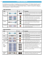
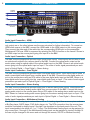
14471 091608
ii
QUICK START GUIDE USER MANUAL - REFERENCE 70
© 2008 B & K Components Ltd. All rights reserved.
The information in this manual is copyright protected. No part of this manual may be copied or reproduced in any form
without prior written consent from B & K Components, Ltd.
B & K Components Ltd. SHALL NOT BE LIABLE FOR OPERATIONAL, TECHNICAL OR EDITORIAL
ERRORS/OMISSIONS MADE IN THIS MANUAL. The information in this manual may be subject to change
without prior notice.
Accessories Included
1
1
1
1
1
- SR10.1 Remote Control
- AM Antenna
- FM Dipole Antenna
- Power Cord
- S-Video to RCA Adapter
1 - Information CD
1 - Warranty Card
1 - Serial to RJ-45 Adapter
B&K
S IMPLY B ETTER!
SIMPLY BETTER! is a copyright of B & K Components, Ltd. All other brand or product names are trademarks or registered trademarks of their respective companies or organizations.
Limited Warranty
B & K Components Ltd., referred to herein as B & K , warrants your B & K equipment (excluding remote control) against all defects in material and workmanship for a period of five years from the date of purchase. The remote control is warrantied for a period of one year. This warranty applies only to
the original purchaser and only to equipment in normal residential use and service. Defective equipment must be returned to B & K , prepaid, accompanied by proof of purchase and sufficient payment to cover the cost of return shipping and handling, and will be repaired or replaced at the discretion of
B & K whose decision as to the method of reparation will be final.
This warranty shall not apply to any equipment which is found to have been improperly installed, incorrectly fused, misused, abused, or subjected to
harmful elements, used in any way not in accordance with instructions supplied with the unit, or to have been modified, repaired or altered in any way
without the expressed, written consent of B & K . This warranty does not apply to the cabinet or appearance items such as the faceplate or control buttons, nor does it cover any expenses incurred in shipping the unit to and from the manufacturer's service department.
This warranty on B & K Components, Ltd. products is NOT VALID if the products have been purchased from an unauthorized dealer or an E-tailer or if
the original factory serial number has been removed, defaced or replaced in any way. B & K Components, Ltd. sells its products through authorized
dealers in order to insure that consumers obtain proper dealer service and support. Buying from an authorized B & K Components, Ltd. dealer insures
that you have a FACTORY WARRANTY on your B & K Components, Ltd. product. If you have any questions concerning your Factory Warranty call
B & K Components, Ltd. at 716-656-0026.
Upgradability: B & K is one the first manufacturers in the audio/video industry to consistently offer software and hardware upgrades to its processing of
audio signals. Through upgrades B & K delivers exceptional value to its customers. But what is "Upgradability"? Upgradability is not a guarantee; we
define it as a philosophy of designing and manufacturing products so that as audio technology evolves, B & K can provide enhancements and improvements to its products that are economically viable.
THE EXPRESS FACTORY WARRANTY HEREIN CONTAINED IS IN LIEU OF ANY AND ALL OTHER WARRANTIES, EXPRESSED OR IMPLIED,
INCLUDING ANY WARRANTY OF MERCHANTABILITY, UPGRADABILITY OR OF FITNESS FOR ANY PARTICULAR PURPOSE. B & K COMPONENTS, LTD. SHALL NOT UNDER ANY CIRCUMSTANCES BE LIABLE FOR DAMAGES, INCLUDING SPECIAL, INCIDENTAL, EXEMPLARY, PUNITIVE OR CONSEQUENTIAL DAMAGES ARISING OUT OF OR IN CONNECTION WITH THE PURCHASE, USE OR PERFORMANCE OF ANY B & K
PRODUCT.
This warranty gives you specific legal rights. Your may also have other rights which vary from State to State. Some States do not allow the exclusion or
limitation of incidental or consequential damages and the foregoing exclusions may not apply to you.
No agent, representative, dealer or employee of B & K has the authority to increase or alter the obligations or terms of this warranty.
Returning Equipment
No equipment may be returned to B & K Components Ltd. without a RETURN AUTHORIZATION (RA). Should you find it necessary to return equipment to B & K , for any reason, a RETURN AUTHORIZATION (RA) number must be issued by B & K in respect of the equipment being returned. You
may request an RA number by calling B & K at the numbers below. We will need the following information to issue your RA number. Please have it
ready before you call.
1.
Your name, address, and phone number.
2.
The model and serial number of the equipment being returned.
3.
A description of the problem being experienced.
4.
Your sales receipt.
Your call will be referred to a Technical Service Representative who will work with you to resolve the problem. If it is determined that the unit must be
returned for repair, an RA number will be issued.
2100 Old Union Road Buffalo, NY 14227 1-800-543-5252 In NY: 716-656-0026
e-mail: [email protected] Web Site: www.bkcomp.com
fax: 716-656-1291
1
TABLE OF CONTENTS
ACCESSORIES AND LIMITED WARRANTY
TABLE OF CONTENTS
FRONT AND BACK PANEL
CONNECTION OVERVIEW
VIDEO INPUT CONNECTIONS
Video Input Connection - HDMI
Video Input Connection - Component Video
Video Input Connection - S-Video
Video Input Connection - Composite
AUDIO INPUT CONNECTIONS
Audio Input Connection - HDMI
Audio Input Connection - Optical
Audio Input Connection - Coax Digital
Audio Input Connection - Stereo Analog
Audio Input Connection - Multichannel Analog
AUDIO/VIDEO OUTPUT
Audio Output Connection - Unbalanced
Audio Output Connection - Balanced
CONFIGURATION AND CONTROL
GUI On-Screen Overlay Interface
Ethernet Communication
RS-232 Communication
SAFETY PRECAUTIONS
SPECIFICATIONS
Product Information
Date of Purchase:
Model #:
Serial #:
Purchased From:
Address:
Phone #:
ii
1
2
4
5
5
5
5
5
6
6
6
6
6
6
7
7
7
8
8
8
8
9
Back Cover
2
FRONT AND BACK PANEL
2
1
3
7
24 23 22
8
4
5
6
9 10
21
11
20
12
19
13
14
18
17
15
16
1.
the
Left Hand Knob - The left and side selector knob is a 5-position rotating knob which serves multiple functions. Pushing in
direction of up, down, left or right will scroll through the left hand side options which include Input, Tuning, Station, Audio
and Video. Rotating the knob will change the highlighted option when available.
2.
Display - The preamplifier contains a 16 character by 2 row display. It will display current status of the preamplifier and any
changes being performed.
3.
Right Hand Knob - The right hand side selector knob is a 5-position rotating knob which serves multiple functions. Pushing
in the direction of up, down, left or right will scroll through the right hand side options which include Volume, Bass, Treble,
Center and Subwoofer. Rotating the knob will change the highlighted option when available.
4.
Main power switch - Removes all power to the preamplifier. Normal operation of the preamplifier requires the power switch
to remain on. Use the SLEEP button for daily on and off of the preamplifier. SLEEP places the unit in standby mode, which
allows turning back on with the remote control. Turn the preamplifier off using the Main Power switch when the preamplifier is
not used for extended periods of time.
5.
Front panel buttons - Front panel buttons serve the following functions:
Sleep - Toggles the unit in and out of standby mode (ON or OFF).
Mute - Toggles the unit in and out of a mute state (ON or OFF).
Menu - Enters into and out of the on-screen menu system.
Save - Save the selected setting such as a Preference or Menu option.
Enter - Selection button for the desired preference.
Arrows - Navigate through the menu.
FRONT AND BACK PANEL
6.
Headphone Jack - Headphones having a standard 1/4” stereo plug can be connected to the headphone output.
7.
Control Output - 1/8” Mono Mini-jack (Tip+ Ring -) source of 12VDC (100mA) Control output for controlling external devices,
such as amplifiers and projection screens. A 12V (100 mA) signal is sent or stopped when the IR, RS-232 or Ethernet com
mand for CTRL+ or CTRL- is sent.
Amp Enable - 1/8” Mono Mini-jack (Tip+ Ring -) source of 12VDC (100mA) Control output for controlling external devices,
such as amplifiers and projection screens. A 12V signal is sent when the preamplifier is out of the standby mode.
8.
Restore - Sometimes it is advisable to restore the unit to a factory default state in order to clear problematic system operation. Pushing in the button for 5 seconds will restore all settings to factory default. A factory restore will clear all system set
tings, Audio and Video preferences. Restore may be seleced by simultaneously pressing Sleep, Up and the Right Encoder
knob.
9.
USB 2.0 - USB 2.0 connection for use of configuring and controlling the preamplifier. Feature is not enabled at this time.
Please see www.bkcomp.com for updates, when available.
10.
RS-232 Control Port - RS-232 RJ-45 input/output for computer interface and RS-232 serial controller applications.
Ethernet Control Port - Ethernet RJ-45 input for flashing the software in the preamplifier. Also used for computer interface
and Ethernet control applications.
11.
FM/AM Tuner - Respective connections for attaching the included AM and FM tuner antennas for internal tuner reception.
12.
Coax Digital Audio Inputs - A total of 8 coax digital audio inputs for connecting coax digital audio signals from the source to
the preamplifier.
Coax Digital Audio Output - A single coax digital audio output for use with another audio device. The audio output is
sourced from the selected audio input.
13.
RCA Surround Outputs - 7.1 Surround outputs for driving external power amplifiers or powered speakers. Channels are
labeled respectively.
14.
RCA Analog Audio Inputs - A total of 8 stereo analog RCA inputs to be configured for use as 8 stereo pairs of analog
inputs, a 5.1 analog input (for use with inputs 5 through 7), or a 7.1 analog input (for use with inputs 5 through 8).
Configuration settings can be found in the menu and BK Suite.
RCA Analog Record Output - A total of 1 stereo pair of analog RCA outputs for connecting an analog RCA audio signal
from the preamplifier to the recording device.
15.
Digital Optical Audio Inputs - A total of 8 optical digital audio inputs for connecting optical digital audio signals from the
source to the preamplifier.
Digital Optical Audio Output - A single optical digital audio output for use with another audio device. The audio output is
sourced from the selected audio input.
16.
Component Video Inputs - A total of 8 component video inputs for standard and high definition video signals.
Component Video Outputs - Component video pass through which also carries sources upconverted to component video.
17.
AES-EBU Input - Connections for a digital balanced input from a source with a AES-EBU output.
18.
Balanced Surround (XLR) Outputs - Connections for 7.1 speakers to connect to an amplifier(s) with balanced inputs.
Balanced Source (XLR) Inputs - Connections for a stereo, analog input from a source with a balanced output.
19.
IR Flashers, All IR Output and IR In - 1/8” Mono Mini-jack connections for IR routing. Flasher outputs allow IR routing for up
to 14 source components. All IR Output will send all IR information being sent to the unit from the Keypad input, the front
panel or the mini-jack IR input. IR Input allows an IR signal to be sent into the unit in order to control the preamplifier
or the source components.
20.
Keypad Connection and IR Daisy Chaining - RJ-45 Keypad Connection provides a 12VDC power, common ground, RS232 transmit, IR Data IN, and 12V control output trigger. The preamplifier will support up to 5 daisy-chained B&K keypads.
The IR Chain connection would link the preamplifier to a CT product for full two-way communication.
21.
Three-position Phoenix Adapter - Phoenix connection for using a Page / Event system with the preamplifier. Feature is not
enabled at this time. Please see www.bkcomp.com for updates, when available.
22.
HDMI Inputs/Output - High Definition Multimedia Interface (HDMI) connections including 6 inputs and 1 output.
Connections carry both the digital audio and digital video signal simultaneously.
23.
AC Input Receptacle - For attaching the supplied AC power cord to the unit.
24.
AC Fuse Holder - Holds the AC line fuse. Replace only with same type and value 2A fast blow. Note: The voltage rating
label is located on the AC fuse holder cover plate.
3
4
CONNECTION OVERVIEW
The following is an overview of connections found on the Reference 70. Further information can be
found later in the quick guide or in the Reference 70 manual. This guide should only be used for
reference only. It is recommended an authorized B&K installer or dealer is contacted for integration
of the preamplifier in advanced installations.
VIDEO INPUT CONNECTIONS
Composite
Source
S-Video
Source
Component
Source
HDMI Source
Video Input Connection - HDMI
The HDMI connection carries both audio and video, although it is possible on the B&K product to
only output one or the other (please see the menu structure for further information). To connect an
HDMI video source to the B&K, connect the HDMI cable to the HDMI output on the source piece.
Then connect the other end of the cable into the corresponding HDMI input on the preamplifier.
Shown is an HDMI output on the source piece going into Input 9 on the B&K.
Video Input Connection - Component Video
The B&K surround preamplifier provides eight sets of component video inputs. Each component
input corresponds to a set of stereo analog inputs, optical digital inputs and coax digital inputs. For
example, Component video input 1 would correspond to Analog Stereo input 1, Optical digital input 1
and Coax digital input 1. The standard component video output would upconvert the input video signal to 720P, 1080i or 1080P depending on the menu selection. Under default configuration the output
is set to 1080i. Shown above is a component video source going into Input 1 on the B&K.
Video Input Connection - S-Video
The B&K surround preamplifier provides eight sets of component video inputs. These inputs can be
used with the S-Video to RCA adapter that is supplied with the preamplifier in order to upconvert an
S-Video signal to go into the component input. Connect the one end of the S-Video to RCA adapter
to the S-Video output on the source piece. Then connect RCA cables from the adapter to the corresponding colored inputs on the B&K. Shown is an S-Video source connected to the S-Video to RCA
adapter with RCA connections going into the blue and green inputs on Input 3.
Video Input Connection - Composite Video
The B&K surround preamplifier provides eight sets of component video inputs. These inputs can be
used to upconvert a composite video signal to go into the component input. Connect the composite
video output on the source piece using an RCA cable to the red colored input on the B&K. Shown is
a composite video source with an RCA connection going into the red input on Input 1.
5
6
AUDIO INPUT CONNECTIONS
Analog
Source
Coaxial Digital
Source
Optical Digital
Source
HDMI Source
Audio Input Connection - HDMI
The HDMI connection carries both audio and video, although it is possible on the B&K product to
only output one or the other (please see the menu structure for further information). To connect an
HDMI audio source to the B&K, connect the HDMI cable to the HDMI output on the source piece.
Then connect the other end of the cable into the corresponding HDMI input on the preamplifier.
Multichannel PCM over HDMI is supposed by selecting the DVD-A function on the remote. Shown is
an HDMI output on the source piece going into Input 9 on the B&K.
Audio Input Connection - Optical
The B&K surround preamplifier provides eight optical audio inputs. These inputs can be used to send
an optical audio signal from a source piece to the B&K. Connect the optical audio output on the
source piece using an optical cable to the optical audio input on the B&K. Shown is an optical audio
source going into the optical audio input on Input 1.The order of audio signal precedence per each
input is Optical Digital -> Coax Digital -> Stereo Analog.
Audio Input Connection - Coax Digital
The B&K surround preamplifier provides eight coax digital audio inputs. These inputs can be used to
send a coax digital audio signal from a source piece to the B&K. Connect the coax digital audio output on the source piece using an RCA cable to the coax digital audio input on the B&K. Shown is a
coax digital audio source going into the coax digital audio input on Input 1.The order of audio signal
precedence per each input is Optical Digital -> Coax Digital -> Stereo Analog.
Audio Input Connection - Stereo Analog
The B&K surround preamplifier provides eight pairs of stereo analog audio inputs. These inputs can
be used to send a stereo analog audio signal from a source piece to the B&K. Connect the stereo
analog audio output on the source piece using a RCA cable to the analog stereo audio input on the
B&K. Shown is a stereo analog audio source going into the stereo analog audio input on Input 1.The
order of audio signal precedence per each input is Optical Digital -> Coax Digital -> Stereo Analog.
Audio Input Connection - Multichannel Analog
The Multichannel Analog input carries either a 5.1 or 7.1 analog signal from a source piece such as
a Blu-Ray player, SACD player, DVD-Audio player, etc. The RCA connection from the source piece
would be connected to analog inputs 5 through 9 as described on the back panel of the unit. The
input is assignable to be either a 5.1 or 7.1 input. The Multichannel Analog input can be assigned to
any source input 1 through 9 (the Multichannel Analog input can be assigned to inputs 9 through 14
but can only be changed in the menu and not through the remote, RS-232 or Ethernet function).
AUDIO/VIDEO OUTPUT
Audio Output Connection - Unbalanced
The Reference 70 supplies 7.1 RCA surround outputs. These surround outputs can be used to connect to an external amplifier and/or the subwoofer to the preamplifier. To connect seven amplifier
channels, connect seven RCA audio cables between the surround outputs and the amplifier inputs.
Be sure to match the appropriate preamp output to the speakers location in the room. For example,
connect the center channel output the the center speaker amplifier channel. If a five channel audio
system is desired, do not connect the surround back audio channels. If a six channel audio system is
desired, connect the sixth channel to the surround back left channel.
Shown is the Reference 70 unbalanced outputs
connected using standard RCA cables to the unbalanced inputs on a Reference 125.7. The subwoofer
output is shown going to a powered sub.
Audio Output Connection - Balanced
The Reference 70 supplies 7.1 RCA surround outputs. These surround outputs can be used to connect to an external amplifier and/or the subwoofer to the preamplifier. To connect seven amplifier
channels, connect seven RCA audio cables between the surround outputs and the amplifier inputs.
Be sure to match the appropriate preamp output to the speakers location in the room. For example,
connect the center channel output the the center speaker amplifier channel. If a five channel audio
system is desired, do not connect the surround back audio channels. If a six channel audio system is
desired, connect the sixth channel to the surround back left channel.
To Balanced
Input on
Amplifier
7
8
CONFIGURATION AND CONTROL
There are a few different ways to achieve control and configuration of the Reference 70. Using the
component video or HDMI output on the Reference 70 you can get the on-screen menu GUI to an
HD monitor. Ethernet or RS-232 communication can also be used using a serial or ethernet control
device or a PC. Some restrictions may apply. Please see the full manual or the B&K website for further information.
GUI On-Screen Overlay Interface
To program the unit using the on-screen menu system use the component video or HDMI output to
your High Definition television or monitor. Note: The menu output is 720p, 1080i, 1080p ONLY.
The front panel display or SR 10.1 remote can be used to navigate the menu system. For specific
menu structure examples please see the full Reference 70 manual.
Ethernet Communication
Typically a router would be used in a situation for Ethernet communication. This is because a router would
assign an IP address to the B&K unit. Only in advanced situations would a static IP address would be used.
Connection Instructions
1. Make sure that all devices are powered off, including the B&K, Router, PCs, switches, etc.
2. Connect one end of an Ethernet network cable to one of the numbered ports on the back of the Router.
Connect the other end to the Ethernet port on the B&K. Repeat this step to connect more PCs or other network devices to the Router. Power the router as needed.
3. Connect your cable or DSL modem’s Ethernet cable to the Router’s Internet port. Power on the cable or
DSL modem, B&K product, router, etc.
6. Power on your PC(s). Open the necessary B&K programs and either configure or control the Reference 70.
Note: Please see the full Reference 70 manual for further information.
Shown is a network router which
would assign an IP
address to the
B&K.
To Network
To Computer
RS-232 Communication
Plug one end of a RJ-45 terminated straight through CAT-5 cable into the serial communications port on the
back of the computer using the serial DB-9 to RJ-45 Adapter. Plug the other end of the RJ-45 terminated
cable into the RS-232 I/O port on the Preamplifier. Once your COM settings are determined, configure the B&K
Suite and B & K Editors for simple and easy setup. Note that many modern laptops do not come equipped with
a DB-9 style serial port. If your computer only has a USB style serial port, you'll need to obtain a USB to DB-9
Serial port adapter cable.
B & K offers a pre-made connector suitable for connecting a serial port to a standard network CAT-5 cable with
RJ-45 connectors. However, if you wish to make your own, please contact B&K Components for the pin connection.
SAFETY PRECAUTIONS
Installation Considerations
CAUTION
RISK OF ELECTRIC SHOCK
DO NOT OPEN
WARNING: to prevent fire or shock hazard, do not expose this unit to rain or moisture. Care should
be taken to prevent objects or liquid from entering the enclosure. Never handle the power cord with
wet hands.
• The lightning flash with arrowhead within a triangle is intended to alert the user of the presence of
uninsulated "dangerous voltage" within the product's enclosure that may constitute a risk of electric
shock to you.
• The exclamation point within a triangle is intended to alert the user of the presence of important
operating and maintenance (servicing) instructions in the literature accompanying the unit.
• Caution: To prevent the risk of electric shock, do not remove cover. No user-serviceable parts inside.
Refer servicing to qualified service personnel.
• If an outdoor antenna is installed, be sure it is grounded to provide some protection against voltage
surges and built up static charges. Keep outdoor antennas away from power lines.
• Unplug the preamplifier from the AC outlet when plugging in or unplugging cables, when left unused
for an extended period of time, when moving the preamplifier, or when you suspect lightning in your
area.
• Prevent damage to the power cord. Replace the power cord if it becomes damaged in any way.
Always grasp the plug on the power cord when plugging or unplugging the preamplifier from the AC outlet.
• Your system may produce sound levels capable of causing permanent hearing loss. Do not operate
for extended periods of time at high volume levels.
• Protect the preamplifier from impact and place the preamplifier on a level surface.
• The preamplifier is equipped with raised feet to provide ventilation, reduce acoustic feedback, and
protect against scratching the surface the unit is resting on. B & K advises against removing the feet.
• Do not stack anything on top of the preamplifier (processor, source, etc.) Leave a minimum of 3"
clearance from the top of the preamplifier to the next shelf (or component).
• The preamplifier should be located away from sources sensitive to heat.
• Do not perform any internal modifications to the preamplifier.
• Always connect the preamplifier's power cord to a dedicated AC outlet for normal operation.
• If young children are present, adult supervision should be provided until the children are capable of
following all rules for safe operation.
• Mistaking CONTROL OUTPUT or IR INPUT connectors for audio/video inputs or outputs may damage your preamplifier or other components.
The preamplifier should be serviced by qualified personnel when:
A.
B.
C.
D.
The preamplifier is not functioning properly.
Objects have entered the chassis.
The preamplifier was exposed to rain or any other type of moisture.
The preamplifier was dropped, or the chassis is damaged.
9
SPECIFICATIONS
Specification
Reference 70
Preamplifier Surround Outputs
7.1 RCA Type
7.1 Balanced (XLR)
Dolby Digital / Dolby Pro Logic IIx / Dolby Digital Surround-EX
DTS / DTS-ES Discrete / NEO:6
20 - 20kHz
Freescale DSP 56371 (upgradable)
90 mV
92 dB unbalanced / 98 dB balanced
10 kΩ
221 Ω
3V RMS
10 Video / 10 Audio / 40 Tuner
14 (6 HDMI)
2 (1 Pair)
8 Coax / 8 Optical / 1AES-EBU
Yes
5.1/ 7.1 (assignable)
Yes
Yes
120 / 220 / 240 VAC (optional / switchable)
Two 10 - 12VDC triggers @ 100mA
17”
19”
6.601”
7.125”
15.087”
15.087”
32 lbs.
50 Watts
Surround Sound Processing
Frequency Response
Processor Type
Input Sensitivity
Signal to Noise Ratio
Input Impedance
Output Impedance
Maximum Output Level
User Presets
Audio / Video Source Inputs
Balanced (XLR) Source Inputs
Digital Coax / Optical Audio Inputs
CK1.1 / 2.2 Keypad Compatible
Multichannel Analog Inputs
Tape Record Loop Outputs
RS-232 / Ethernet Controllable
AC Line Voltage
Control Outputs
Dimensions in Inches
Width
(Cutout Dimensions)
Height
Depth
Shipping Weight
Power Consumption
Replacement Fuses
AC Line - 2 Amp / 250 Volt Fast Blow
Tuner Specifications
Specification
FM Section
AM Section
Frequency Range
87.5 - 107.9 MHz
520 - 1670 kHz
Total Harmonic Distortion
Less than 0.25%
Less than 0.3%
20 Hz - 15 kHz
300 Hz - 3kHz
IHF (Usable) Sensitivity
12 dBf
28 dBf
Alternate Chan. Selectivity
65 dB
30 dB
Signal to Noise Ratio
70 dB
50 dB
Antenna Input Impedance
75 Ω
300 Ω
15 / 35 dBf
N/A
2 dB
N/A
Frequency Response
Mono/Stereo Sensitivity
Capture Ratio
Video Specifications
Frequency Response Composite / S-Video
Frequency Response Component Video
Input & Output Impedance
Composite / S-Video / Component Inputs and Outputs
HDMI Inputs / Outputs
Max. Input / Output Level (RCA & S)
HDMI Specifications
20 Hz - 10 MHz
10 Hz - 75 MHz
75 Ω / 75 Ω
8/1
6/1
2V RMS into 75 Ω
1.3a Compliant