1
M9961-03E090
Service Manual
3JH4(B)(C)(M)E
M9961-03E090
Publication No.
M9961-03E090
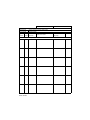
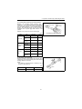
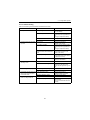
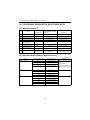
History of Revision
Manual Name
Service Manual for Marine Diesel Engine
Engine Model:
3JH4(B)(C)(M)E
Number
Date of Reason for
of
revision correction
revision
New edition
Printed in Japan
M9961-03E090
January 2004
Outline of correction
Correction item
No (page)
Corrected
by
FOREWORD
This service manual has been complied for engineers engaged in sales, service, inspection and
maintenance. Accordingly, descriptions of the construction and functions of the engine are emphasized
in this manual, while items, which should already be common knowledge, are omitted.
One characteristic of a marine diesel engine is that its performance in a vessel is governed by the
applicability of the vessel's hull construction and its steering system.
Engine installation, fitting out and propeller selection have a substantial effect on the performance of the
engine and the vessel. Moreover, when the engine runs unevenly or when trouble occurs, it is essential
to check a wide range of operating conditions - such as installation to the full and suitability of the ship's
piping and propeller - and not just the engine itself. To get maximum performance from this engine, you
should completely understand its functions, construction and capabilities, as well as proper use and
servicing.
Use this manual as a handy reference in daily inspection and maintenance, and as a text for engineering
guidance.
Model 3JH4E has been used for the illustrations in this service manual, but they apply to other models in
the JH4 series engines.
California
Proposition 65 Warning
California
Proposition 65 Warning
Diesel engine exhaust and some of its
constituents are known to the State of
California to cause cancer, birth defects, and other reproductive harm.
Battery posts, terminals, and related accessories contain lead and lead compounds, chemicals known to the State
of California to cause cancer and reproductive harm.
Wash hands, after handling.
The contents of this service manual may not be copied or
reproduced without permission.
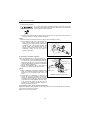
FOR SAFTY
1. SAFETY LABELS
• Most accidents are caused by negligence of basic safety rules and precautions. For accident
prevention, it is important to avoid such causes before development to accidents.
Please read this manual carefully before starting repair or maintenance to fully understand safety
precautions and appropriate inspection and maintenance procedures.
Attempting at a repair or maintenance job without sufficient knowledge may cause an unexpected
accident.
• It is impossible to cover every possible danger in repair or maintenance in the manual. Sufficient
consideration for safety is required in addition to the matters marked
. Especially for
safety precautions in a repair or maintenance job not described in this manual, receive instructions
from a knowledgeable leader.
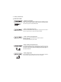
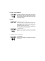
• Safety marks used in this manual and their meanings are as follows:
DANGER-indicates an imminent hazardous situation which, if
not avoided, WILL result in death or serious injury.
WARNING-indicates a potentially hazardous situation which, if
not avoided, COULD result in death or serious injury.
CAUTION-indicates a potentially hazardous situation which, if
not avoided, may result in minor or moderate injury.
• NOTICE - indicates that if not observed, the product performance or quality may not be
guaranteed.
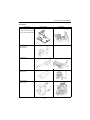
2. Safety Precautions
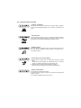
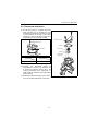
(1) SERVICE AREA
• Sufficient Ventilation
Inhalation of exhaust fumes and dust particles may be hazardous to ones
health. Running engines welding, sanding, painting, and polishing tasks
should be only done in well ventilated areas.
• Safe / Adequate Work Area
The service area should be clean, spacious, level and free from holes in
the floor, to prevent "slip" or "trip and fall" type accidents.
• Clean, orderly arranged place
No dust, mud, oil or parts should be left on the floor surface.
[Failure to Observe]
An unexpected accident may be caused.
• Bright, Safely Illuminated Area
The work area should be well lit or illuminated in a safe manner. For work
in enclosed or dark areas, a "drop cord" should be utilized. The drop cord
must have a wire cage to prevent bulb breakage and possible ignition of
flammable substances.
• Safety Equipment
Fire extinguisher(s), first aid kit and eye wash / shower station should be
close at hand (or easily accessible) in case of an emergency.
(2) WORK - WEAR (GARMENTS)
• Safe Work Clothing
Well fitting !!
Appropriate safety wear (gloves, special shoes/boots, eye/ear protection,
head gear, harness', clothing, etc.) should be used/worn to match the
task at hand. Avoid wearing jewelry, unbuttoned cuffs, ties or loose fitting
clothes around moving machinery. A serious accident may occur if caught
in moving/rotating machinery.
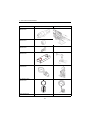
(3) TOOLS
• Appropriate Lifting / Holding
When lifting an engine, use only a lifting device (crane, jack, etc.) with
sufficient lifting capacity. Do not overload the device. Use only a chain,
cable, or lifting strap as an attaching device. Do not use rope, serious
injury may result.
To hold or support an engine, secure the engine to a support stand, test
bed or test cart designed to carry the weight of the engine. Do not
overload this device, serious injury may result
Never run an engine without being properly secured to an engine support
stand, test bed or test cart, serious injury may result.
• Appropriate Tools
Always use tools that are designed for the task at hand. Incorrect usage
of tools may result in damage to the engine and or serious personal
injury.
(4) GENUINE PARTS and MATERIALS
• Genuine Parts
Always use genuine YANMAR parts or YANMAR recommended parts
and goods. Damage to the engine, shortened engine life and or personal
injury may result.
(5) FASTENER TORQUE
• Torqueing Fasteners
Always follow the torque values and procedures as designated in the
service manual. Incorrect values, procedures and or tools may cause
damage to the engine and or personal injury.
(6) Electrical
• Short Circuits
Always disconnect the (-) Negative battery cable before working on the
electrical system. An accidental "short circuit" may cause damage, fire
and or personal injury. Remember to connect the (-) Negative battery
cable (back onto the battery) LAST
• Charging Batteries
Charging wet celled batteries produces hydrogen gas. Hydrogen gas is
extremely explosive. Keep sparks, open flame and any other form of
ignition away. Explosion may occur causing severe personal injury.
• Battery Electrolyte
Batteries contain sulfuric acid. Do NOT allow it to come in contact with
clothing, skin and or eyes, severe burns will result.
(7) WASTE MANAGEMENT
Observe the following instructions with regard to hazardous waste
disposal. Negligence of these will have a serious impact on environmental
pollution concerns.
1) Waste fluids such as lube oil, fuel and coolant shall be carefully put
into separate sealed containers and disposed of properly.
2) Do NOT dispose of waste materials irresponsibly by dumping them
into the sewer, overland or into natural waterways.
3) Waste materials such as oil, fuel, coolant, solvents, filter elements and
batteries, must be disposed of properly according to local ordinances.
Consult the local authorities or reclamation facility.
(8) FURTHER PRECAUTIONS
• Fueling / Refueling
Keep sparks, open flames or any other form of ignition (match, cigarette,
etc.) away when fueling/refueling the unit. Fire and or an explosion may
result.
• Hot Surfaces.
Do NOT touch the engine (or any of its components) during running or
shortly after shutting it down. Scalding / serious burns may result. Allow
the engine to cool down before attempting to approach the unit.
• Rotating Parts
Be careful around moving/rotating parts. Loose clothing, jewelry, ties or
tools may become entangled causing damage to the engine and or
severe personal injury.
• Preventing burns from scalding
1) Never open the radiator filler cap shortly after shutting the engine
down.
Steam and hot water will spurt out and seriously burn you. Allow the
engine to cool down before attempt to open the filler cap.
2) Securely tighten the filler cap after checking the radiator.
Steam can spurt out during engine running, if tightening loose.
• Safety Label Check
Pay attention to the product safety label.
A safety label (caution plate) is affixed on the product for calling special
attention to safety.
If it is missing or illegible, always affix a new one.
3. Precautions for Service Work
(1) Precautions for Safety
Read the safety precautions given at the beginning of this manual carefully and always mind safety in
work.
(2) Preparation for Service Work
Preparation is necessary for accurate, efficient service work. Check the customer ledger file for the
history of the engine.
• Preceding service date
• Period/operation hours after preceding service
• Problems and actions in preceding service
• Replacement parts expected to be required for service
• Recording form/check sheet required for service
(3) Preparation before Disassembly
• Prepare general tools, special service tools, measuring instruments, oil, grease, non-reusable parts,
and parts expected to be required for replacement.
• When disassembling complicated portions, put match-marks and other marks at places not
adversely affecting the function for easy reassembly.
(4) Precautions in Disassembly
• Each time a parts is removed, check the part installed state, deformation, damage, roughening,
surface defect, etc.
• Arrange the removed parts orderly with clear distinction between those to be replaced and those to
be used again.
• Parts to be used again shall be washed and cleaned sufficiently.
• Select especially clean locations and use clean tools for disassembly of hydraulic units such as the
fuel injection pump.
(5) Precautions for Inspection and Measurement
Inspect and measure parts to be used again as required to determine whether they are reusable or not.
(6) Precautions for Reassembly
• Reassemble correct parts in correct order according to the specified standards (tightening torques,
and adjustment standards). Apply oil important bolts and nuts before tightening when specified.
• Always use genuine parts for replacement.
• Always use new oil seals, O-rings, packing and cotter pins.
• Apply sealant to packing depending on the place where they are used. Apply of grease to sliding
contact portions, and apply grease to oil seal lips.
(7) Precautions for Adjustment and Check
Use measuring instruments for adjustment to the specified service standards.
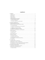
CONTENTS
1. GENERAL ....................................................................................................................... 1
1.1 Exterior Views ..........................................................................................................................1
1.2 Specifications ...........................................................................................................................2
1.3 Engine Outline ..........................................................................................................................4
1.4 Piping Diagrams ....................................................................................................................... 7
1.5 Exhaust Gas Emission Regulation ...........................................................................................9
1.5.1 Engine identification (3JH4E)............................................................................................................ 9
1.5.2 Exhaust Gas Regulations ............................................................................................................... 10
1.5.3 Guarantee Conditions for Emission Standard................................................................................. 10
2. Inspection and Adjustment ............................................................................................ 12
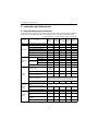
2.1 Periodic Maintenance Schedule .............................................................................................12
2.2 Periodic Inspection and Maintenance Procedure ...................................................................14
2.2.1 Check before starting...................................................................................................................... 14
2.2.2 inspection after initial 50 hours or one month operation ................................................................. 17
2.2.3 Inspection every 50 hours or monthly ............................................................................................. 22
2.2.4 Inspection every 250 hours or one year.......................................................................................... 26
2.2.5 Inspection every 1,000 hours or four years..................................................................................... 31
2.3 Adjusting the no-load maximum or minimum speed ..............................................................38
2.4 Sensor Inspection ..................................................................................................................38
2.4.1 Oil pressure switch ................................................................... 38
2.4.2 Thermo switch ....................................................................... 38
2.5 Thermostat inspection ............................................................................................................39
2.6 Adjusting Operation ................................................................................................................40
2.6.1 Preliminary Precautions .................................................................................................................. 40
2.6.2 Adjusting operation procedure ........................................................................................................ 40
2.6.3 Check Points and Precautions During Running.............................................................................. 41
2.7 Long storage ..........................................................................................................................42
3. Troubleshooting ............................................................................................................. 43
3.1 Preparation before troubleshooting ........................................................................................43
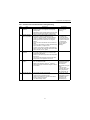
3.2 Quick Reference Chart for Troubleshooting ...........................................................................44
3.3 Troubleshooting (Concerning engine and fuel injection equipment) ......................................53
3.4 Troubleshooting by measuring Compression Pressure .........................................................56
4. Disassembly and Reassembly ...................................................................................... 58
4.1 Disassembly and Reassembly Precautions ...........................................................................58
4.2 Disassembly and Reassembly Tools .....................................................................................59
4.2.1 General Handtools .......................................................................................................................... 59
4.2.2 Special Handtools ........................................................................................................................... 62
4.2.3 Measuring Instruments ................................................................................................................... 65
4.2.4 Other material ................................................................................................................................. 66
4.2.5 Measuring Instruments ................................................................................................................... 69
4.3 Disassembly and Reassembly ...............................................................................................72
4.3.1 Disassembly.................................................................................................................................... 72
4.3.2 Reassembly .................................................................................................................................... 82
5. Inspection and Servicing of Basic Engine Parts ............................................................ 93
5.1 Cylinder Block ........................................................................................................................93
5.1.1 Inspection of parts........................................................................................................................... 93
5.1.2 Cleaning of oil holes .................................................................. 93
5.1.3 Color check procedure.................................................................................................................... 93
5.1.4 Replacement of cup plugs .............................................................................................................. 94
5.1.5 Cylinder bore measurement............................................................................................................ 95
5.2 Cylinder Head ........................................................................................................................96
5.2.1 Inspecting the cylinder head ........................................................................................................... 97
5.2.2 Valve seat correction procedure........................................................ 98
5.2.3 Intake/exhaust valves, valve guides .................................................... 99
5.2.4 Valve springs ................................................................................................................................ 101
5.2.5 Assembling the cylinder head......................................................... 102
5.2.6 Measuring top clearance ............................................................. 102
5.2.7 Intake and exhaust rocker arms ....................................................... 103
5.2.8 Adjustment of valve clearance ...................................................................................................... 103
5.3 Piston and Piston Pins ..........................................................104
5.3.1 Piston ............................................................................................................................................ 104
5.3.2 Piston pin .......................................................................... 105
5.3.3 Piston rings ........................................................................ 105
5.4 Connecting Rod ................................................................108
5.4.1 Inspecting the connection rod......................................................... 108
5.4.2 Crank pin metal............................................................................................................................. 109
5.4.3 Piston pin bushing .................................................................. 111
5.4.4 Assembling piston and connecting rod ................................................. 111
5.5 Crankshaft and Main Bearing ...............................................................................................112
5.5.1 Crankshaft..................................................................................................................................... 112
5.5.2 Main bearing ....................................................................... 115
5.6 Camshaft and Tappets .........................................................................................................116
5.6.1 Camshaft .......................................................................... 116
5.6.2 Tappets ......................................................................................................................................... 118
5.7 Timing Gear .........................................................................................................................119
5.7.1 Inspecting the gears...................................................................................................................... 119
5.7.2 Gear timing marks .................................................................. 119
5.8 Flywheel and Housing ..........................................................................................................120
5.8.1 Position of top dead center and fuel injection timing..................................................................... 120
5.8.2 Damper disc and cooling fan ........................................................................................................ 121
6. FUEL INJECTION EQUIPMENT ................................................................................. 122
6.1 Fuel Injection Pump/Governor .............................................................................................122
6.1.1 Fuel system diagram ................................................................ 122
6.1.2 Fuel injection pump service data .................................................................................................. 123
6.1.3 Fuel injection pump structure........................................................................................................ 125
6.1.4 Removing a fuel injection pump.................................................................................................... 127
6.1.5 Installing a fuel injection pump...................................................................................................... 127
6.1.6 Adjusting fuel injection timing........................................................................................................ 127
6.1.7 Troubleshooting of fuel injection pump ......................................................................................... 128
6.1.8 Major faults and troubleshooting................................................................................................... 128
6.1.9 Tools ............................................................................................................................................. 131
6.2 Fuel Feed Pump ................................................................133
6.2.1 Construction of fuel feed pump........................................................ 133
6.2.2 Fuel feed pump specifications ...................................................................................................... 133
6.2.3 Disassembly and reassembly of fuel feed pump .......................................................................... 134
6.2.4 Fuel feed pump inspection............................................................................................................ 134
6.3 Fuel Filter .....................................................................136
6.3.1 Fuel filter specifications................................................................................................................. 136
6.3.2 Fuel filter inspection ...................................................................................................................... 136
6.4 Fuel Tank .............................................................................................................................137
7. INTAKE AND EXHAUST SYSTEM ............................................................................. 138
7.1 Intake System ......................................................................................................................138
7.1.1 Breather system (A reductor to intake air system of blowby gas)........................... 138
7.1.2 Diaphragm assy inspection........................................................................................................... 139
7.2 Exhaust System ...................................................................................................................140
7.2.1 Construction.................................................................................................................................. 140
7.2.2 3Mixing elbow inspection .............................................................................................................. 140
8. LUBRICATION SYSTEM ............................................................................................. 141
8.1 Lubrication System ...............................................................................................................141
8.2 Lube Oil Pump .....................................................................................................................142
8.2.1 Lube oil pump construction ........................................................... 142
8.2.2 Specifications of lube oil pump ..................................................................................................... 142
8.2.3 Lube oil pump disassembly and reassembly ................................................................................ 142
8.2.4 Lube oil pump inspection .............................................................................................................. 143
8.2.5 Oil pressure control valve construction ......................................................................................... 143
8.3 Lube Oil Filter .......................................................................................................................144
8.3.1 Lube oil filter construction ............................................................ 144
8.3.2 Lube oil filter replacement............................................................................................................. 144
8.4 Lube oil Cooler .....................................................................................................................144
8.4.1 Lube oil cooler construction .......................................................................................................... 144
8.4.2 Inspecting the lube oil cooler ........................................................................................................ 144
8.5 Rotary Waste Oil Pump (Optional) .......................................................................................145
9. Cooling Water System ................................................................................................. 146
9.1 Cooling Water System .........................................................................................................146
9.2 Seawater Pump ....................................................................................................................148
9.2.1 Specifications of seawater pump .................................................................................................. 148
9.2.2 Seawater pump disassembly ........................................................................................................ 149
9.2.3 Seawater pump Inspection ........................................................... 149
9.2.4 Seawater pump reassembly ......................................................................................................... 149
9.3 Fresh Water Pump ..............................................................................................................150
9.3.1 Fresh water pump construction..................................................................................................... 150
9.3.2 Specifications of fresh water pump ............................................................................................... 151
9.3.3 Fresh water pump disassembly .................................................................................................... 151
9.3.4 Fresh water pump inspection........................................................................................................ 151
9.4 Heat Exchanger ...................................................................................................................153
9.4.1 Heat exchanger construction ......................................................... 153
9.4.2 Specifications of heat exchanger ...................................................... 153
9.4.3 Disassembly and reassembly of the heat exchanger ................................................................... 153
9.4.4 Heat exchanger inspection ........................................................................................................... 153
9.5 Pressure cap and coolant recovery tank ..............................................................................154
9.5.1 Pressure cap construction............................................................ 154
9.5.2 Pressure cap pressure control ...................................................................................................... 154
9.5.3 Pressure cap inspection................................................................................................................ 154
9.5.4 Replacing filler neck...................................................................................................................... 155
9.5.5 Function of the coolant recovery tank .................................................. 156
9.5.6 Specifications of coolant recovery tank......................................................................................... 156
9.5.7 Mounting the coolant recovery tank .............................................................................................. 156
9.5.8 Precautions on usage of the coolant recovery tank ...................................................................... 156
9.6 Thermostat ...........................................................................................................................157
9.6.1 Functioning of thermostat ............................................................................................................. 157
9.6.2 Thermostat construction ............................................................. 157
9.6.3 Characteristics of thermostat ........................................................................................................ 157
9.6.4 Thermostat inspection................................................................................................................... 157
9.6.5 Testing the thermostat .................................................................................................................. 157
9.7 Bilge Pump and Bilge Strainer (Optional) ............................................................................158
9.7.1 Introduction ................................................................................................................................... 158
9.7.2 Description .................................................................................................................................... 159
9.7.3 Cautions........................................................................................................................................ 159
9.7.4 Assembly Procedure..................................................................................................................... 160
9.7.5 Cautions for Assembling ............................................................................................................... 162
9.7.6 Troubleshooting ............................................................................................................................ 163
10. Reduction and Reversing Gear ................................................................................. 164
11. REMOTE CONTROL (OPTIONAL) ........................................................................... 165
11.1 Remote Control system ......................................................................................................165
11.1.1 Construction of remote control system ....................................................................................... 165
11.1.2 Remote control device components............................................................................................ 165
11.2 Remote Control Installation ................................................................................................167
11.3 Remote Control Inspection .................................................................................................169
11.4 Remote Control Adjustment ...............................................................................................170
12. Electrical System ....................................................................................................... 171
12.1 Electrical System ..............................................................171
12.1.1 Wiring diagram............................................................................................................................ 172
12.2 Battery ................................................................................................................................174
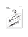
12.3 Starting Motor .....................................................................................................................175
12.3.1 Specifications.............................................................................................................................. 175
12.3.2 Characteristics .................................................................... 175
12.3.3 Structure ..................................................................................................................................... 176
12.3.4 Wiring diameter of a starting motor............................................................................................. 177
12.4 Alternator Standard, 12V/60A ............................................................................................178
12.4.1 Specifications.............................................................................................................................. 178
12.4.2 Structure ..................................................................................................................................... 179
12.4.3 Wiring diagram .................................................................... 180
12.4.4 Standard output characteristics .................................................................................................. 180
12.4.5 Inspection.................................................................................................................................... 181
12.5 Alternator 12V/80A (Optional) ............................................................................................182
12.5.1 Specifications.............................................................................................................................. 182
12.5.2 Structure ..................................................................................................................................... 183
12.5.3 Wiring diagram .................................................................... 184
12.5.4 Standard output characteristics .................................................................................................. 184
12.6 Instrument Panel ................................................................................................................185
12.6.1 B-type instrument panel (optional).................................................... 185
12.6.2 C-type instrument panel ............................................................ 185
12.7 Warning Devices ................................................................................................................186
12.7.1 Oil pressure alarm....................................................................................................................... 186
12.7.2 Sender unit for lube oil pressure gauge ............................................... 187
12.7.3 Cooling water temperature alarm................................................................................................ 188
12.7.4 Sender unit for the cooling water temperature gauge ................................... 188
12.8 Air Heater (Optional) ..........................................................................................................189
12.9 Electric Engine Stopping Device (Optional) .......................................190
13. SERVICE STANDARDS ............................................................................................ 191
13.1 Engine Tuning ....................................................................................................................191
13.2 Engine Body .......................................................................................................................192
13.2.1 Cylinder head.............................................................................................................................. 192
13.2.2 Camshaft and gear train ............................................................................................................. 193
13.2.3 Cylinder block ............................................................................................................................. 194
13.3 Lubricating Oil System (Trochoid Pump) ...........................................................................196
14. TIGHTENING TORQUE FOR BOLTS AND NUTS ................................................... 197
14.1 Main Bolt and Nut ...............................................................................................................197
14.2 Standard Bolts and Nuts (without lube oil) .........................................................................197
1. GENERAL
1. GENERAL
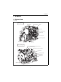
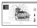
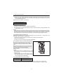
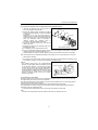
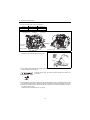
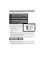
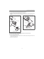
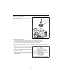
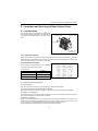
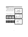
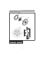
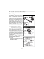
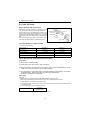
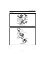
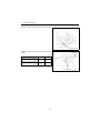
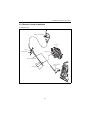
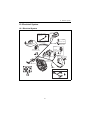
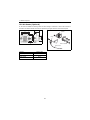
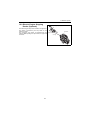
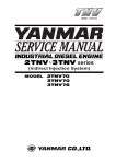
1.1 Exterior Views
(1) 3JH4E
Operating Side
Intake silencer
Intake manifold
Dipstick
Fuel filter
Fuel injection pump
Oil filter cap
Fuel feed pump
Lubricating oil filter
Shift lever
Marine gear
Oil cooler
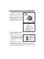
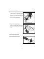
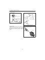
Non-Operating Side
Engine name plate (on the rocker arm cover)
Fresh water filler cap
Coolant tank / Heat exchanger
Alternator
Exhaust manifold
Mixing elbow
Starter motor
Sea water pump
<Note> This illustration shows the 3JH4E with Yanmar marine gear (Model:KM35P).
1
1. GENERAL
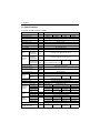
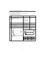
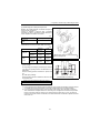
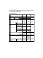
1.2 Specifications
(1) 3JH3E, 3JH3BE, 3JH3CE, 3JH4ME
Official engine model name
unit
3JH4E
Company internal model name
-
3JH4E
3JH4BE
3JH4CE
3JH4ME
Marine gear model
-
KM35P
KM35A
SD40
Bobtail
Use
-
Pleasure use
Type
-
Vertical water cooled 4 cycle diesel engine
Combustion system
-
Direct injection
Air charging
-
Naturally aspirated
Number of cylinders
-
3
Bore x stroke
mm(inch)
88 x 90 (3.46 x 3.54)
Displacement
L
1 .642
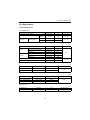
Output at
crankshaft /
Engine speed
kW(HP)/
min-1
26.7(36.3) / 2907 (at Fuel temp. 25°C)*
Output at
crankshaft /
Engine speed
kW(HP)/
min-1
29.4(40.0) / 3000 (at Fuel temp. 25°C)*
28.7(39.0) / 3000 (at Fuel temp. 40°C)* *
Continuous
power
Fuel stop
power
Output at
kW(HP)/ 28.0(38.1) / 3000 (at Fuel temp. 25°C)*
propeller shaft /
min-1 27.4(37.3) / 3000 (at Fuel temp. 40°C) **
Engine speed
Installation
-
-
Flexible mounting
Fuel injection timing
deg b.T.D.C.
FID 12±1 (FIC-Air 13±1)
Fuel injection opening
pressure
MPa
(kgf/cm2)
21.6±0.5 (2.12±0.05)
-
At flywheel side
Crankshaft
-
Counter-clockwise viewed from stern
Propeller shaft
(Ahead)
-
Main power take off
Direction of
rotation
Clockwise viewed from stern
-
-
-
Cooling system
-
Fresh water cooling with heat exchanger
Lubrication system
-
Complete enclosed forced lubrication
L(quart)
Engine:4.5 (4.8), Coolant recovery tank : 0.8 (0.8)
Cooling water capacity (fresh)
Rake angle
Lubricating
oil capacity
(engine)
deg.
Total (Note 4)
Oil pan only
Engine
Dimension
Type
at rake angle 0 deg
L(quart) 4.5±0.3 (4.8±0.3) 5.0±0.3 (5.3±0.3) 5.0±0.3 (5.3±0.3) 5.0±0.3 (5.3±0.3)
1.1 (1.2)
1.2 (1.3)
1.2 (1.3)
-
Electric
Starting motor
V-kW
DC 12V-1.4 kW
AC generator
V-A
12V-60A (12V-80A optional)
Overall length
Overall width
mm(inch)
Overall height
Flywheel major dimension
Engine dry mass
(include marine gear)
-
5.0±0.3 (5.3±0.3) 5.5±0.3 (5.8±0.3) 5.5±0.3 (5.8±0.3) 5.5±0.3 (5.8±0.3)
Effective (Note 5)
Starting
system
at rake angle 8 deg
777 (30.6)
776 (30.6)
700 (27.6)
700 (27.6)
539 (21.2)
539 (21.2)
539 (21.2)
539 (21.2)
623 (24.5)
623 (24.5)
623 (24.5)
623 (24.5)
mm(inch)
kg
1.2 (1.3)
Ø300 x 66 (11.8 x 2.6)
185
186
2
212
(engine:173)
173
1. GENERAL
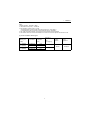
(Note)
1. Rating condition : ISO 3046-1, 8665
2. 1HP (metric horse power) ≒ 0.7355 kW
3. Fuel condition : Density at 15°C = 0.842
* Fuel temperature 25°C at the inlet of the fuel injection pump. (ISO 3046-1)
** Fuel temperature 40°C at the inlet of the fuel injection pump. (ISO 8665)
4. The "Total" oil quantity includes: oil in oil pan and oil in channels, coolers and filter.
5. The effective amount of oil shows the difference in maximum scale of the dipstick and minimum scale.
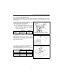
(2) Sales condition, Marine gear
Reduction ratio
(Marine gear
model)
No. of blades
Moment of
propeller inertiaI propeller
materials
GD2
2
2
N•m (kgf•m )
Outer diameter
of propeller
(inch)
2.61 (KM35P)
2.64 (KM35A)
3 (A/R=0.52)
18
4 (A/R=0.69)
17
2.36 (KM35P)
2.33 (KM35A)
3 (A/R=0.52)
18
4 (A/R=0.69)
17
Engine
application
2.94 (0.30)
Bronze
2.55 (0.26)
3
3JH4(B)E
78
3-M10 X 1.5
DEPTH 14 / 20
7
120
+0.025
0
60
50
210
PC
210
10.5
100
50 +0.025
0
32
4-
7.5
4
DETAIL OF COUPLING
SCALE 1:3
DETAIL OF PULLEY
SCALE 1:3
12 X 30
MOUNTING BLOCKS ID#100
174
206
538.6
517.6
(274)
169.3
243.6
412
143
190
4
194.1
(202.5)
16
7
191.2
65 32
MIN. 100
MAX. 110
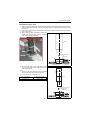
NOTE
1. The original height of mounting blocks is shown
in this drawing. Engine weight will compress
blocks by 4mm (approx).
2. The figures marked with
show the dimensions
with u-mixing elbow, or optional coupling.
(65)
622.6
431.4
)
AL
N
IO
PT
(O
ROTATION
93.2
120.4
330
480
(72.5)
6
724.3
777.3
47
1. GENERAL
DIRECTION OF ROTATION
6
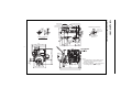
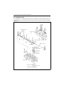
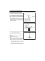
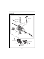
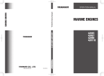
1.3 Engine Outline
U-MIXING ELBOW
(1) 3JH4E (with KM35P marine gear)
MOUNTING BLOCKS ID#150
174
MIXING ELBOW
U-MIXING ELBOW
DIRECTION OF ROTATION
7.5
210
6
3-M10 X 1.5
DEPTH 14 / 20
60
210
+0.025
0
+0.025
0
7
DETAIL OF PULLEY
SCALE 1:3
DETAIL OF COUPLING
SCALE 1:3
12 X 30
174
206
538.6
517.6
(274)
168
243.6
5
MOUNTING BLOCKS ID#100
143
412
190
622.6
(202.5)
431.4
)
AL
N
IO
PT
(O
194.1
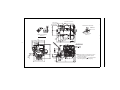
(2) 3JH4BE(with KM35A Marine gear)
MOUNTING BLOCKS ID#150
MIXING ELBOW
ASTERN
79.5
NOTE
1. The original height of mounting blocks is shown
in this drawing. Engine weight will compress
blocks by 4mm (approx).
2. The figures marked with
show the dimensions
with u-mixing elbow, or optional coupling.
191.2
7
16
MIN. 100
MAX. 110
32
ROTATION
AHEAD
(72.5)
5.955
723
776
47
1. GENERAL
93.2
120.4
330
480
210
210
3-M10 X 1.5
DEPTH 14 / 20
60
+0.025
0
DIRECTION OF ROTATION
MOUNTING BLOCKS ID#200
538.6
517.6
(274)
12 X 30
174
DETAIL OF PULLEY
SCALE 1:3
206
185
243.6
143
(202.5)
(266.4)
1036.4
641.4
605
7
210
32
(112.5)
372
420
480
395
MAX. 110
MIN. 105
431.4
6
16
(202.5)
)
AL
N
IO
PT
(O
194.1
538
(185)
538
143
47
973
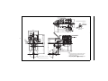
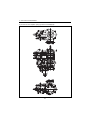
Available propeller dia. 181 inch max.
NOTE
1. The original height of mounting blocks is shown
in this drawing. Engine weight will compress
blocks by 4mm (approx).
2. The figures marked with show the dimensions
with u-mixing elbow, or optional coupling.
1. GENERAL
7
(3) 3JH4CE (with SD40 sail drive)
MOUNTING BLOCKS ID#200
1.General
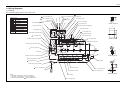
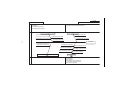
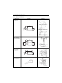
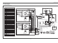
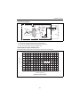
1.4 Piping Diagrams
(1) 3JH4(B) E
Note: The following piping diagram is for the 3JH4E model.
7.8 x t4.5 rubber hose
Overflow
7.8 x t4.5 rubber hose
Screw joint (Union)
Check valve
Flange joint
7.8 x t4.5 rubber hose
Fuel oil filter (cartridge type)
Eye joint
5 x t4.5
rubber hose
Fuel injection pump
26
4.76 x t0.7 steel pipe
C
Insertion joint
Drill hole
Fuel feed pump
30
Marks of piping
Fuel oil inlet
7.8 x t4.5 rubber hose
7.8 x t4.5 rubber hose
Detail of part A
9 x t3.5 rubber hose
Lubricating oil filter (cartridge type)
Pressure control valve
45
Cooling fresh water piping
Lubricating oil piping
Fuel oil piping
Lubricating oil pump
Lubricating oil cooler
D
5 x t4.5 rubber hose
Fresh water temperature switch
P
76.3
Cooling seawater piping
Fuel high pressure pipe
Fuel injection nozzle
27 x t4 rubber hose
Detail of part B
9 x t3.5 rubber hose
To oil pan
Hot water connection inlet (R3/8)
Cooling water pump (fresh water)
Oil pressure switch
P
9
8
28.6 x t2 copper pipe
Thermostat
From
cylinder
head To cam shaft
17
T
P
B
Hot water connection outlet (R3/8)
Detail of part C
28 x t4 rubber hose
28 x t4 rubber hose
Mixing elbow
P
8.5
8
25.4 x t4.3 rubber hose
A
Seawater inlet
16.5
Cooling water pump (seawater)
Fresh water cooler
Lubricating oil inlet filter
Notes
1. Dimension of steel pipe : outer dia. x thickness.
Dimension of rubber pipe : inner dia. x thickness.
2. Fuel rubber pipes (marked ) satisfy EN/ISO7840.
Main bearing
25 x t1.8 copper pipe
7
25.4 x t4.3 rubber hose
25.4 x t4.3 rubber hose
Detail of part D
1.General
(2) 3JH4CE (with sail drive SD40)
7.8 x t4.5 rubber hose
Overflow
7.8 x t4.5 rubber hose
Screw joint (Union)
Check valve
Flange joint
Eye joint
7.8 x t4.5 rubber hose
Fuel oil filter (cartridge type)
Insertion joint
7.8 x t4.5 rubber hose
Fuel oil inlet
7.8 x t4.5 rubber hose
Marks of piping
Fuel feed pump
5 x t4.5
rubber hose
Fuel injection pump
4.76 x t0.7 steel pipe
C
9 x t3.5 rubber hose
Drill hole
Cooling fresh water piping
Lubricating oil filter (cartridge type)
Pressure control valve
45
Cooling seawater piping
Lubricating oil pump
Fuel oil piping
Lubricating oil cooler
D
76.3
Lubricating oil piping
5 x t4.5 rubber hose
Fresh water temperature switch
P
Fuel high pressure pipe
Fuel injection nozzle
27 x t4 rubber hose
Detail of part B
9 x t3.5 rubber hose
To oil pan
Hot water connection inlet (R3/8)
Cooling water pump (fresh water)
Oil pressure switch
9
P
8
28.6 x t2 copper pipe
Thermostat
T
From
cylinder
head
To cam shaft
17
P
B
Hot water connection outlet (R3/8)
Detail of part C
28 x t4 rubber hose
28 x t4 rubber hose
8.5
Mixing elbow
P
16.5
Cooling water pump (seawater)
8
Fresh water cooler
25.4 x t4.3 rubber hose
Lubricating oil inlet filter
25.4 x t4.3 rubber hose
25.4 x t4.3 rubber hose
25.4 x t4.3 rubber hose
Detail of part D
Notes
1. Dimension of steel pipe : outer dia. x thickness.
Dimension of rubber pipe : inner dia. x thickness.
2. Fuel rubber pipes (marked ) satisfy EN/ISO7840.
Main bearing
25 x t1.8 copper pipe
8
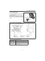
1.general
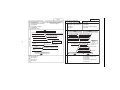
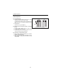
1.5 Exhaust Gas Emission Regulation
The EPA and ARB (,California Air Resources Board)
Off-road Compression Ignition engines regulations
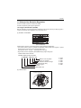
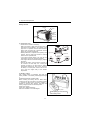
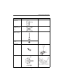
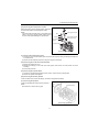
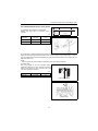
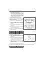
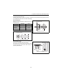
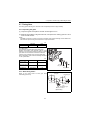
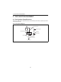
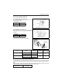
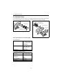
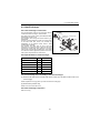
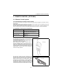
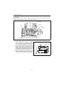
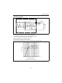
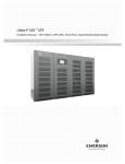
1.5.1 Engine identification (3JH4E)
With the regulations on exhaust gas emission worldwide, it has become necessary to identify engines in
a manner to determine which regulations they comply with, hence
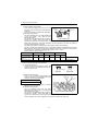
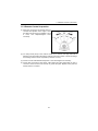
(1) Emission control label
(EPA and ARB label)
(Note) Emission Control is accomplished through Engine Modification (EM-Design)
• The tamper resistance device is installed with EPA/ARB certified 3JH4E series engines to prevent
illegal change of fuel injection volume and high idling speed.
(Fuel injection volume : cap type, High idling speed : cap type)
• Engine family name as assigned by EPN/ARB identifying engine family group
4YDXM1.64D3N and this identifies
YYDXM1.64D3N and this identifies
4 YDX M 1.64 D 3 N
Method of air aspiration
Number of cylinders
Combustion chamber design
Displacement (liter)
Marine engine
Yanmar
*2004 Model Year
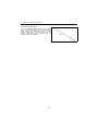
(2) Label location:
Emission control label
9
Y : 2000
1 : 2001
2 : 2002
3 : 2003
4*: 2004
5 : 2005
1.General
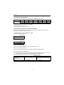
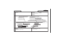
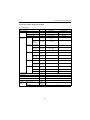
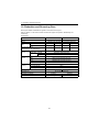
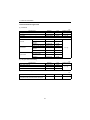
1.5.2 Exhaust Gas Regulations
This engine conforms to the EPA exhaust gas regulations (19kW and under 37kW).
Engine Power
Tier
Model Year
NOx
HC
NMHC + NOx
CO
PM
19 <= kW < 37
(25 <= hp < 50)
Tier 1
1999
-
-
9.5 (7.1)
5.5 (4.1)
0.80 (0.60)
Tier 2
2004
-
-
7.5 (5.6)
5.5 (4.1)
0.60 (0.45)
Note
1. The transit smoke (ACC/LUG/PEAK) is not applicable.
2. The EPA recommended fuel is used.
3. The ARB standard is the same as the EPA's.
1.5.3 Guarantee Conditions for Emission Standard
In addition to making sure that these conditions are met, check for any deterioration that may occur
before the required periodic maintenance times.
(1) Requirement on engine installation condition
(a) Air intake negative pressure
kPa (mmAq)
Permissible
¹3.9 (400)
(b) Exhaust gas back pressure
kPa (mmAq)
Permissible
¹14.7 (1500)
(2) Fuel oil and lubricating oil
(a) Fuel: The diesel fuel oil [BS 2869 A1 or A2 (Cetane No.45 min.)]
(b) Lube oil : API grade, class CD
(3) Do not remove the caps restricting injection quantity and engine speed.
(4) Perform maintenance without fail.
Note : Inspections to be carried out by the user and by the maker are divided and set down in the "List of
Periodic Inspection" on the operation manual and should be checked carefully.
EPA allows to apply Maintenance schedule for Emission related parts as follows.
Maintenance period
Parts Fuel nozzle cleaning
Adjustment, cleaning, repairs for fuel
nozzle, fuel pump, and electronic control
unit etc.
Power Rating
19 ¹ kW < 37
Every 1500 hours
Every 3000 hours
10
1.general
(5) Quality guarantee period for exhaust emission related parts
For exhaust emission related parts, follow the inspections outlined in the "List of Periodic Inspections",
on the operation manual, and use the table below to carry out inspections based on operation hours or
time in years. Whichever comes first is the guarantee period.
19 ¹ kW < 37
3000 hours or 5 years
The specific emissions-related parts are
(a) Fuel injection nozzle
(b) Fuel injection pump
11
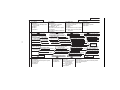
2. Inspection and Adjustment
2. Inspection and Adjustment
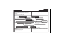
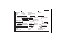
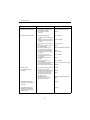
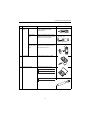
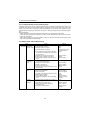
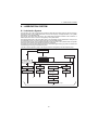
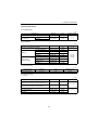
2.1 Periodic Maintenance Schedule
The engine periodic inspection timing is hard to determine as it varies with the application, load status,
qualities of the fuel and lubricating oils used and handling status. General rules are described here.
{ : User-maintenance
System
Whole
Item
Before
starting
Visual inspection of engine outside
{
Check the fuel level, and refill
{
Drain the fuel tank
Fuel system
Å : Parts replacement z : Shop-inspection
*2 Initial
50hrs. or
one month
*2 Every
50hrs. or
one month
{
Drain the fuel/water separator
*2 Every
250 hrs. or 1000 hrs. or
one year
{
Å
Replace the fuel filter
z
z*1
Check the injection spray condition
Check the lube oil Crankcase
level
Marine gear
{
{
Replace the lube Crankcase
oil
Marine gear
Å
Å
Å
Å
Replace the engine lube oil filter.
Å
Å
Seawater outlet
{
(During
operation)
Check cooling water level
Cooling
system
{
Check the impeller of the cooling
water pump (seawater pump)
Replace the fresh water
{
z
Clean the element of the air intake
silencer
-
Clean the exhaust/water mixing
elbow
{
Diaphragm assembly inspection
z
Check the alarm lamps & devices
Electrical
system
Å
Every year
When long life coolant of the specified type is used, the
replacement period of two years can be obtained.
Clean & check the water passages
Air intake
and
exhaust
system
4 years
{
Check the injection timing
Lubricating
system
*2 Every
{
Check the electrolyte level in the
battery
{
Adjust the tension of the alternator
driving belt
{
Check the wiring connectors
{
{
12
Å
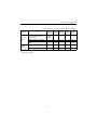
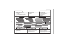
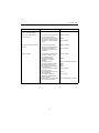
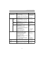
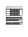
2. Inspection and Adjustment
{ : User-maintenance
System
Cylinder
head,
etc.
Item
Check the leakage of water,
lube oil and fuel.
Before
starting
*2 Initial
*2 Every *2 Every
*2 Every
50hrs. or 50hrs. or 250 hrs. or 1000 hrs. or
one month one month one year
4 years
{
(After
starting)
Retighten all major nuts and bolts
z
Adjust intake/exhaust valve
clearance
Check/adjust the remote control
Remote
operation
control
system, etc. Adjust the propeller shaft alignment
{
*1 For
*2
Å : Parts replacement z : Shop-inspection
EPA requirements see also 1.5 in chapter 1.
Whichever comes first
13
z
z
{
z
z
z
2. Inspection and Adjustment
2.2 Periodic Inspection and Maintenance Procedure
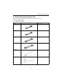
2.2.1 Check before starting
Be sure to check the following points before starting an engine every day.
No.
Inspection Item
(1)
Visual inspection of engine outside
(2)
Check the fuel level, and refill
(3)
Check the lube oil level (Crankcase/Marine gear)
(4)
Seawater outlet
(5)
Check cooling water level
(6)
Check the alarm lamps & devices
(7)
Check the leakage of water, lube oil and fuel.
(8)
Check/adjust the remote control operation
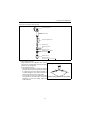
(1) Visual inspection of engine outside
If any problem is found, do not use before the engine repairs have been completed.
• Oil leak from the lubrication system
• Fuel leak from the fuel system
• Cooling water leak from the cooling water system
• Damaged parts
• Loosened or lost bolts
• Fuel, coolant tank rubber hoses, V belt cracked, loosened clamp
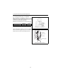
(2) Check the fuel level, and refill
Check the remaining fuel oil level in the fuel tank and refuel the recommended fuel if necessary.
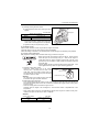
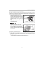
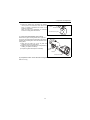
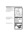
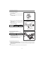
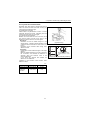
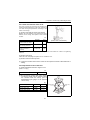
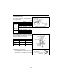
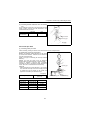
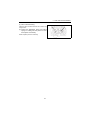
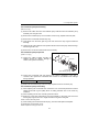
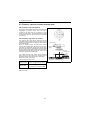
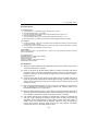
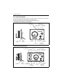
(3) Check the lube oil level (Crankcase/Marine
gear)
1) Checking engine lube oil level
a) Check the lube oil level of a engine with a
dipstick. Insert the dipstick fully and check the oil
level. The oil shall not be contaminated heavily
and have appropriate viscosity. No cooling water
or diesel fuel shall be mixed.
Rocker arm cover
Filter port
Dipstick
Upper limit
Lower limit
Standard
The level shall be between the upper and lower limit
lines on the dipstick.
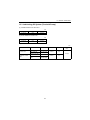
Unit: liter(quart)
Model
Engine oil capacity
at rake angle 8 degree
3JH4E with KM35P
Full : 5.0 ± 0.3 (5.3 ± 0.3)
3JH4E with KM35A
3JH4E with SD40
Full : 5.5 ± 0.3 (5.8 ± 0.3)
b) If the remaining engine oil level is low, fill the oil pan with the specified engine oil to the specified
level through the filler port.
[NOTICE]
The engine oil should not be overfilled to exceed the upper limit line. If engine oil is overfilled, the
engine may intake the engine oil in the combustion chamber during the operation, and white smoke, oil
hummer or urgent rotation may occur, because the blowby gas is reduced in the suction air flow.
14
2. Inspection and Adjustment
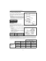
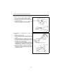
2) Checking marine gear lube oil level
a) Check the lube oil level of the marine gear with a
dipstick.
Oil filler cap
Unit: liter(pint)
Dipstick
Marine gear oil capacity
KM35P
Full : 0.50 (1.0)
KM35A
Full : 0.65 (1.4)
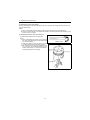
b) When the level is low, remove a filler port cap at
the top of the housing, and fill it with marine gearclutch- lube oil to the upper limit on the dipstick.
c) Tighten the filler port cap securely by hand.
(4) Seawater outlet
Check whether seawater comes out just after the engine has started.
If seawater doesn't come out, shut down the engine immediately.
Check the leakage of seawater in the seawater pass and the damage of the seawater pump impeller.
(5) Check cooling water level
Daily inspection of cooling water should be done only by coolant recovery tank.
• Never open the filler cap while the engine is still hot. Steam and hot
water will spurt out and seriously burn you. Wait until the engine is
cooled down after the engine stopped, wrap the filler cap with a rag
piece and turn the cap slowly to gently release the pressure inside the
flesh water tank.
• Securely tighten the filler cap after checking the flesh water tank. If the
cap is tightened loosely, steam can spurt out during operation.
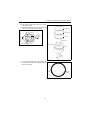
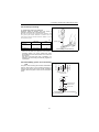
1) Checking cooling water volume
Check the cooling water level in the coolant
recovery tank. If the water level is close to the
LOW mark, open the coolant recovery tank cap
and replenish the coolant recovery tank with clean
soft water to the FULL mark.
Standard
The water level of the coolant recovery tank shall
be between the upper and lower limit lines.
Cap
To fresh water
cooler
Rubber hose
FULL
Coolant recovery tank
LOW
2) Replenishing engine with water
If the cooling water levelin the coolant recovery tank is lower than the LOW mark, open the filler cap
and check the cooling water level in the coolant tank. Replenish the engine with the cooling water,
if the level is low.
• Check the cooling water level when the engine is cool.
Checking when the engine is hot is dangerous. And the water volume is expanded due to the
temperature.
• Daily cooling water level check and replenishing shall be done only at the coolant recovery tank.
Usually do not open the filler cap to check or replenish.
Standard
Cooling water volume
(Unit: liter)
Engine
Coolant recovery tank
4.5
0.8
15
2. Inspection and Adjustment
IMPORTANT:
If the cooling water runs short quickly or when the coolant tank runs short of water with the coolant
recovery tank level unchanged, water may be leaking or the air tightness may be lost. Increase in the
water level of the coolant recovery tank during operation is not abnormal.
The increased water in the coolant recovery tank returns to the coolant tank when the engine is cooled
down.
If the water level is normal in the coolant recovery tank but low in the coolant tank, check loosened
clamping of the rubber hose between the coolant tank and coolant recovery tank or tear in the hose.
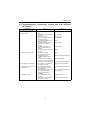
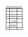
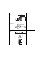
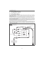
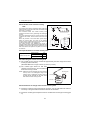
(6) Check the alarm lamps & devices
Before and after starting the engine, check to see that the alarm functions normally. Failure of alarm
cannot warn the lack of the engine oil or the cooling water. Make it a rule to check the alarm operation
before and after starting engine every day.
When the sensor detects a problem during operation, the lamp comes on and the buzzer goes off.
Alarm lamps are located on the panel, buzzer is located on the back of panel.
Under normal conditions, the monitors are off. When there is a problem, the monitors light up.
Battery low
charge alarm
When the alternator output is too low, the lamp will come on.
When charge begins, the lamp will turn off.
(The alarm buzzer will not sound, when the lamp comes on.)
Coolant high
temperature
alarm
When the temperature reaches the maximum (95°C [203F] or higher), the
lamp will light.
Continuing operation at temperatures exceeding the maximum limit will
result in damage and seizure.
Check the load and the fresh water cooling system for any abnormalities.
Lubricating oil
low pressure
alarm
When the lubricating oil pressure falls below normal, the oil pressure sensor
will register this and the lamp will come on and alarm will sound.
Continuing operation with insufficient oil pressure will result in
damage and seizure.
Check the oil level.
Water in sail
drive seal
alarm
When seawater is detected between the seals of sail drive, the lamp will
come on and the alarm will sound.
Water in fuel
filter alarm
(C type only)
This function is not available on this engine.
Seawater
insufficient
flow alarm
(C type only)
This function is not available on this engine.
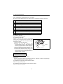
Normal action of alarm devices
Alarm devices act as shown below. Check that the alarm lamps and buzzer are working normally,
when the key is turned on.
Key switch
OFF → ON
START → ON
Engine
Before start
Running
Goes on
Stop
Light
Off
Off
Off
Light
Off
Off
Off
Alarm buzzer
Battery low charge alarm
Alarm lamps
Coolant high temperature alarm
Lubricating oil low pressure alarm
Water in sail drive seal alarm
16
2. Inspection and Adjustment
(7) Check the leakage of water, lube oil and fuel.
Brfore and after starting the engine, check the leakage of cooling water and seawater from cooling water
system. Also check the leakage of lube oil and fuel.
(8) Check/adjust the remote control operation
Make sure that the accelerator of a boat can be operated smoothly before starting the engine. If it feels
heavy to manipulate, lubricate the accelerator cable joints and pivots. Adjust the accelerator cable if
there is a dislocation or excessive play between the accelerator and the governor lever.
2.2.2 inspection after initial 50 hours or one month operation
Be sure to check the following points after initial 50 hours or one month operation, whichever comes first.
No.
Inspection Item
(1)
Drain the fuel tank
(2)
Replace the engine lube oil and the lube oil filter
(3)
Replace the marine gear lube oil
(4)
Adjust the tension of the alternator driving belt
(5)
Adjust the intake/exhaust valve clearance
(6)
Check/adjust the remote control operation
(7)
Adjust the propeller shaft alignment
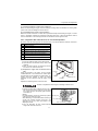
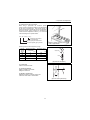
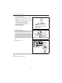
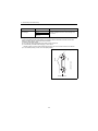
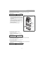
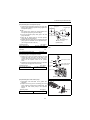
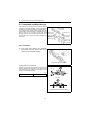
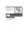
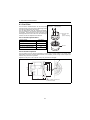
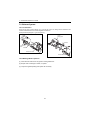
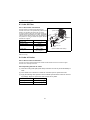
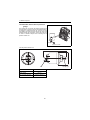
(1) Drain the fuel tank
1) Put a pan under the drain cock to catch the fuel.
2) Open the drain cock and drain off any water or dirt
collected.
3) When the water and dirt are drained off and the
fuel comes out, close the drain cock.
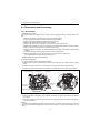
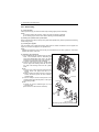
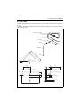
(2) Replace the engine lube oil and the lube oil
filter.
During the operation of an engine, the oil is quickly
contaminated due to the initial wear of internal parts.
The lubricating oil must therefore be replaced early. It is
easiest and most effective to drain the engine
lubricating oil after operation while the engine is still
warm.
Replace the lubricating oil filter at the same time.
Fuel pipe
To engine
Drain cock
Sediment
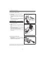
Beware of oil splashes if extracting the Lubricating oil while it is hot
1) Remove the lubricating oil dipstick and also the oil
filler cap at the top of the rocker arm cover. Attach
the oil drain pump to the dipstick guide and drain
off the lube oil.
[Notice]
For easier draining, remove the oil filler cap (yellow)
at the top of the rocker arm cover.
When lubricating oil is absorbed without removing a
oil filler cap, negative pressure grows big in the
crankcase and it may cause the rubber of the
diaphragm cracked.
2) Turn the lubricating oil filter counter-clockwise
using a filter wrench to remove it.
17
Dipstick guide
Lube oil filter
Filter wrench
2. Inspection and Adjustment
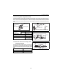
3) Moisten the new oil filter gasket with the engine oil and install the new engine oil filter manually
turning it clockwise until it comes into contact with the mounting surface, and tighten it further to 3/4
of a turn with the filter wrench.
Tightening torque: 20-24N•m (177-212 lb-in)
Applicable oil filter Part No.
119305-35150
4) Fill with new lubricating oil.
5) Perform a trial run of the engine and check the oil leakage.
6) Approximately 10 minutes after stopping the engine, check the oil level by using the oil dipstick. Add
oil if the level is too low.
[Notice]
When checking the oil level right after the engine running, the oil level in the dipstick guide decreases
drastically, and the accurate oil measurement can't be performed because the pressure in the cylinder
block decreases with the function of the diaphragm in the rocker arm cover. Therefore, measure the
lube oil level after removing the oil filler cap or about 10 minutes later after stopping the engine.
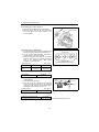
(3) Replace the marine gear lube oil.
During initial operation, the oil is quickly contaminated due to the initial wear of internal parts. The
lubricating oil must therefore be replaced early.
1) Remove the cap from the filler port and attach the oil drain pump. Drain off the oil.
2) Fill with new lubricating oil.
3) Perform a trial run of the engine and check the oil leakage.
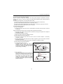
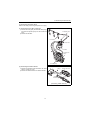
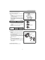
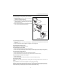
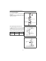
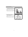
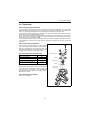
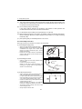
(4) Adjust the tension of the alternator drive belt
When there is not enough tension in the V-belt, it will
slip and the cooling water pump will fail to supply
cooling water. Engine over-heating and the seizure will
occur.
When there is too much tension in the V-belt, the belt
will become damaged more quickly and the bearing of
the cooling water pump may be damaged.
Check and adjust the V-belt tension (deflection) in the
following manner.
[Notice]
Be especially careful not to splash engine oil on the
V-belt, because it will cause slipping, stretching and
aging of the belt.
1) Remove the belt cover. Check the tension of the Vbelt by pressing down on the middle of the belt
with your finger [approx. 98N(10kgf)].
The specified deflection should be as follows.
For used V-belt
8-10mm (0.315-0.393 inches)
For new V-belt
6-8mm (0.236-0.315 inches)
• "New V-belt" refers to a V-belt which has been used less than 5 minutes on a running engine.
• "Used V-belt" refers to a V-belt which has been used on a running engine for 5 minutes or more.
18
2. Inspection and Adjustment
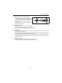
2) If necessary, adjust the V-belt tension (deflection).
To adjust the V-belt tension, loosen the set bolt for
the belt adjuster and move the alternator to tighten
the V-belt.
3) Visually check the V-belt for cracks, oiliness or
wear. If any, replace the V-belt with new one.
Belt adjuster
Set bolt
Alternator
[Notice]
When the V-belt will be replaced with new one,
loosen the set bolt and move the alternator and also
loosen the V-pulley set bolts for the cooling water
pump. Remove the V-belt.
After replacing with a new V-belt and adjusting the
tension, run the engine for 5 minutes and readjust the
deflection to the value in the table above.
Adjust the V-belt tension
inserting a bar
Adjuster
Alternator
(Tension adjustment)
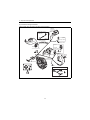
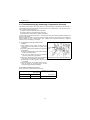
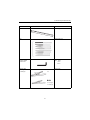
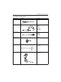
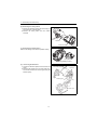
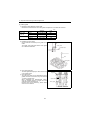
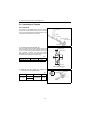
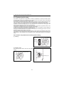
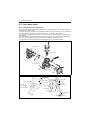
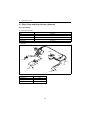
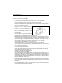
(5) Adjusting the intake/exhaust valve clearance
Flywheel
housing
1
Make measurement and adjustment while the engine is cold.
1) Valve clearance measurement
a) Remove the rocker arm cover above cylinder
head.
b) Set the No.1 cylinder in the compression TDC
Turn the crankshaft to bring the piston of the Injection
timing marks
No.1 cylinder to its compression top dead center
while watching the rocker arm motion, the timing No.1 cylinder
mark of the flywheel housing and the top mark of
T.D.C.
the flywheel.
(Position where both the intake and exhaust
valves are closed.)
Flywheel
Hole
(Notes)
• The crankshaft shall be turned clockwise as seen
from the gear case side.
• The No.1 cylinder position is on the opposite side of the gear case.
• Since there is a clearance between the rocker arm and valve at the compression top dead center, the
position of TDC can be checked by hand Also see that the top mark on the flywheel aligns with the
mark on the flywheel housing. If there is no valve clearance, disassemble and inspect around the
valve seat, since the valve seat may be worn abnormally.
19
2. Inspection and Adjustment
c) Valve clearance measurement
Rocker arm Adjusting screw
Insert a thickness gage between the rocker arm
Valve
and valve cap, and record the measured valve
clearance
Lock nut
clearance.
(Use it as the data for estimating the wear state.)
d) Adjusting other cylinders
Turn the crankshaft 240° and make adjustment
for the No.3 cylinder. Then adjust the No.2
cylinder in this order.
(Valve clearance)
The cylinder to be adjusted first does not have to
be the No.1 cylinder. Select and adjust the
cylinder where the piston is the nearest to the top
dead center after turning, and make adjustment for other cylinders in the order of ignition by
turning the crankshaft 240° each time.
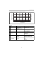
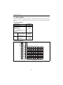
The adjustment method of reducing the flywheel turning numbers (for reference):
Set NO.1 cylinder to the compression T.D.C. and adjust the clearance of the z mark of the below
table. Next, turn the flywheel once (the suction/ exhaust valve of NO.1 cylinder is in the position of
the overlap T.D.C. at this time), and adjust the clearance of the { mark.
Ignition order of 3 cylinder engines: 1 → 3 → 2
Cylinder No.
1
Valve
No.1 compression
T.D.C
2
Suction
Exhaust
Suction
z
z
z
3
Exhaust
Suction
Exhaust
z
No.1 overlap T.D.C
{
The first time
The second time
{
2) Valve clearance inspection and adjustment
a) Loosen adjusting bolts
Loosen the lock nut and adjust the screw. And
check the valve for any inclination of valve cap,
entrance of dirt or wear.
Valve cap
(Normal)
(Abnormal)
b) Measure valve clearance
Insert a 0.2 mm thickness gage between the
rocker arm and valve cap, and adjust the valve
clearance. Tighten the adjusting bolt.
Standard valve clearance (mm)
0.15-0.25
c) Apply oil to the contact surface between
adjusting screw and push rod.
d) Adjusting other cylinders
Turn the crankshaft 240° then and make
adjustment for the No.3 cylinder. Then adjust the
No.2 cylinder in this order.
(Valve clearance adjustment)
The cylinder to be adjusted first does not have to
be the No.1 cylinder. Select and adjust the
cylinder where the piston is the nearest to the top dead center after turning, and make adjustment
for other cylinders in the order of ignition by turning the crankshaft 240° each time.
20
2. Inspection and Adjustment
(6) Check and adjust the remote control operation
The various control levers on the engine side are connected to the remote control lever by the remote
control cable. The cable will become stretched and the attachments loose after long hours of use
causing deviation. It is dangerous to control operation under these conditions, and the remote control
cable must be checked and adjusted periodically.
1) Adjusting the Throttle Remote Control Cable
Check to see that the control lever on the engine
side moves to the high speed stop position and low
speed stop position when the remote control lever
is moved to H (high speed) and L (low speed)
respectively.
When there is deviation, loosen the bracket for the
remote control cable on the engine side and
adjust.
Adjust the high speed stop position first and then
adjust the low speed idling by the adjustment bolt
on the remote control lever.
Fuel injection pump
Remote
control cable
High speed
limiting bolt
Control lever
Cable joint
Low speed limiting bolt
Never adjust the high speed limiting bolt. This will void warranty.
2) Adjusting the Clutch Remote Control Cable
Check that the shift lever moves to the correct
position, when the remote control handle is put in
NEUTRAL, FORWARD and REVERSE position.
Use the NEUTRAL position as the standard for
adjustment. When there is deviation, loosen the
clamp for the remote control cable and adjust the
shift lever position
Remote control cable
Clamp
Marine
gear
Shift lever
(7) Adjust the propeller shaft alignment
The flexible engine mounts is compressed a little in the initial engine operation and it may cause the
centering misalignment between the engine & the propeller shaft.
1) Check unusual noise and vibration of the engine / boat hull, while increasing the engine speed
gradually and lowering it.
2) If there is unusual noise and/or vibration, adjust the propeller shaft alignment. (Refer to 6.4.5
"Centering the Engine" in the installation manual for pleasure boat use.)
21
2. Inspection and Adjustment
2.2.3 Inspection every 50 hours or monthly
Be sure to check the following points every 50 hours or monthly, whichever comes first.
No.
Inspection Item
(1)
Drain the fuel/water separator.
(2)
Check the electrolyte level in the battery
(1) Drain the fuel/water separator.
Air bleeding bolt
1) Close the fuel cock of the fuel tank.
2) Loosen the drain plug and drain off any water and
dirt collected inside.
[NOTE:]
If no drain drips when the drain plug is opened,
loosen the air bleeding plug on the top of the fuel/
water separator by turning counter-clockwise 2-3
times.
(This may occur in case of the fuel/water separator
position is higher than the fuel oil level in the fuel
tank).
3) After draining, be sure to tighten the air bleeding
plug.
4) Be sure to bleed air in the fuel system.
Drain plug
(Fuel/water separator)
22
2. Inspection and Adjustment
Fuel System Air bleeding Procedures
1) Check the fuel level in the fuel tank. Replenish if
Insufficient.
2) Loosen the air bleeding bolt at the top of the fuel/
water separator by turning it 2 or 3 turns. When
fuel, which does not contain air bubbles, comes
out of the bolt hole, tighten the air bleeding bolt.
3) Loosen the air bleeding bolt of the fuel filter by
turning it 2 or 3 turns.
4) Feed fuel with the fuel feed pump by moving the
lever on the left side of the feed pump up and
down.
5) Allow the fuel containing air bubbles to flow out
from the air bleeding bolt hole. When the fuel no
longer contains bubbles, tighten the air bleeding
bolt. This completes the air bleeding of the fuel
system.
6) After the engine start-up, the automatic airbleeding device works to purge the air in the fuel
system. No manual air-venting is required for
normal engine operation.
Air bleeding bolt
Fuel nozzle
To fuel tank
Fuel filter
Fuel injection
pump
Fuel feed pump
(2) Check the electrolyte level in the battery
Fire due to electric short-circuit
• Make sure to turn off the battery switch or disconnect the negative cable
(-) before inspecting the electrical system. Failure to do so could cause
short-circuiting and fires.
• Always disconnect the (-) Negative battery cable first before
disconnecting the battery cables from battery. An accidental "Short
circuit" may cause damage, fire and or personel injury.
And remember to connect the (-) Negative battery cable (back onto the
battery) LAST.
Proper ventilation of the battery area
Keep the area around the battery well ventilated, paying attention to keep
away any fire source. During operation or charging, hydrogen gas is
generated from the battery and can be easily ignited.
Do not come in contact with battery electrolyte
Pay sufficient attention to avoid your eyes or skin from being in contact
with the fluid. The battery electrolyte is dilute sulfuric acid and causes
burns. Wash it off immediately with a large amount of fresh water if you
get any on you.
23
2. Inspection and Adjustment
Battery structure
Terminal
Cap
Cover
Cathode
plate
Separator
Glass mat
Battery
case
Anode plate
(1) Electrolyte level
• Check the level of fluid in the battery.
When the amount of fluid nears the lower limit, fill
with battery fluid (available in the market) to the
upper limit. If operation continues with insufficient
battery fluid, the battery life is shortened, and the
battery may overheat and explode.
• Battery fluid tends to evaporate more quickly in the
summer, and the fluid level should be checked
earlier than the specified times.
• If the engine cranking speed is so slow that the
engine does not start up, recharge the battery.
• If the engine still will not start after charging, replace
the battery.
• Remove the battery from the battery mounting of
the machine unit after daily use if letting the
machine unit leave in the place that the ambient
temperature could drop at -15°C or less. And store
the battery in a warm place until the next use the
unit to start the engine easily at low ambient
temperature.
GREASE
Upper limit
UPPER LEVEL
LOWER LEVEL
OK
Too low
Lower limit
Excessive
Electrolyte level
(2) Battery charge
Use a battery tester or hydrometer and check the
battery condition. If the battery is discharged, recharge
it.
(a) Measurement with a battery tester
When checking the battery with the batter tester,
connect the red clip of the tester to the battery positive
(+) terminal and black clip to the battery negative (-)
terminal by pinching them securely, and judge the
battery charge level from the indicator position.
Green zone: Normal
Yellow zone: Slightly discharged
Red zone: Defective or much discharged
Battery tester
charge measurement
( Battery
)
with battery tester
24
2. Inspection and Adjustment
(b) Measurement with hydrometer
When using a hydrometer, the measured specific
gravity must be corrected according to the temperature
at the time of measurement. The specific gravity of
battery electrolyte is defined with 20°C as the standard.
Since the specific gravity increases or decreases by
0.0007 when the temperature varies by 1°C, correct the
value according to the equation below.
Float
S20 = St + 0.007 ( t - 20 )
Electrolyte temperature
at measurement
Specific gravity at measurement
charge measurement
( Battery
)
with a hydrometer
Converted specific gravity at 20 C
Specific gravity and remaining battery charge
Rubber bulb
Specific
gravity
(20°C)
Discharged quantity
of electricity
(%)
Remaining charge
1.28
0
100
1.26
10
90
1.24
20
80
1.23
25
75
(%)
Glass tube
Float
(Hydrometer structure)
(3) Terminals
Clean if corroded or soiled.
(4) Mounting bracket
Repair or replace it if corroded.
Retighten if loosened.
(5) Battery appearance
Replace the battery if cracked or deformed.
Clean with fresh water if contaminated.
(How to read hydrometer)
25
2. Inspection and Adjustment
2.2.4 Inspection every 250 hours or one year
Be sure to check the following points every 250 hours or one year operation, whichever comes first.
No.
Inspection Item
(1)
Drain the fuel tank
(2)
Replace the fuel filter
(3)
Replace the engine lube oil and the lube oil filter.
(4)
Replace the marine gear lube oil and the lube oil filter.
(5)
Check the impeller of the cooling water pump(seawater pump)
(6)
Replace the fresh water
(7)
Clean the exhaust/water mixing elbow
(8)
Adjust the tension of the alternator driving belt
(9)
Check the wiring connectors
(1) Drain the fuel tank
Refer to 2.2.2(1) for the procedure.
(2) Replace the fuel filter
Replace the fuel filter with new one at the specified
interval, before it is clogged with dust to advesely affect
the fuel flow. Also, replace the fuel filter after the engine
has fully been cooled.
1) Close the fuel cock of the fuel tank.
2) Remove the fuel filter using a filter
wrench(customer procured). When removing the
fuel filter, hold the bottom of the fuel filter with a
piece of rag to prevent the fuel oil from dropping.
3) Clean the filter mounting surface and slightly apply
fuel oil to the gasket of the new fuel filter.
4) Install the new fuel filter manually turning until it
comes into contact with the mounting surface, and
tighten it further to one turn using a filter wrench.
Fuel filter
Tightening torque: 20-24N•m
Applicable fuel filter Part No.
129470-55702
5) Bleed the fuel system. Refer to 2.2.3.(1).
IMPORTANT:
Be sure to use genuine Yanmar part (super fine mesh filter). Otherwise, it results in engine damage,
uneven engine performance and shorten engine life.
(3) Replace the engine lube oil and the lube oil filter.
Refer to 2.2.2(2) for the procedure.
(4) Replace the marine gear lube oil and the lube oil filter.
Refer to 2.2.2(3) for the procedure.
26
2. Inspection and Adjustment
(5) Check the impeller of the cooling water pump (seawater pump).
1) Remove the seawater pump cover and take out
Cover
the O-ring, impeller and wear plate,
O-ring
2) Inspect the rubber impeller, checking for splitting
around the outside, damage or cracks, and replace
Impeller
if necessary.
Wear plate
Depending on the use, the inside parts of a
seawater pump may deteriorate and the discharge
performance may drop. At the specified interval or
when the discharge volume of seawater is
reduced, inspect the seawater pump in
accordance with the following procedures.
3) Loosen the seawater pump cover set bolts and
remove the cover.
Pump body
4) Illuminate the inside of the seawater pump with a
(Sea water pump)
flashlight and inspect.
5) If no damage is found, reassemble the cover
6) If any of the following problems are found, take out the O-ring, impeller and wear plate. If necessary,
replace with new one and reassemble the cover.
• Impeller blades are cracked or nicked. Edges or surfaces of the blades are marred or scratched.
Note: The impeller must be replaced periodically (every 1000 hrs or four years whichever comes first).
• Wear plate is damaged.
7) If a large amount of water leaks continuously from the water drain pipe beneath the seawater pump
during engine operation, check the oil seal inside the seawater pump.
[Notice]
The seawater pump turns in the counterclockwise
direction, but the impeller must be installed by turning
in the clockwise direction. If the impeller has been
removed for any reason and must be reassembled,
be very careful not to make a mistake and turn it in
the wrong direction. Additionally, if the engine is being
turned manually, be careful to turn it in the correct
direction. Incorrect turning will twist the impeller
blades and damage it
Direction of impeller
Impeller
Impeller rotating direction
(6) Replace the fresh water.
Be sure to replace the fresh water every year. When the long life coolant is used of the specified type,
the replacement period of two years can be obtained.
Use clean soft water and be sure to add the Long Life Coolant Antifreeze (LLC) to the cooling water in
order to prevent rust built up and freezing.
Cooling performance drops when cooling water is contaminated with rust and scale.
Even if antifreeze or antirust is added, the cooling water must be replaced periodically because the
properties of the agent will degenerate.
1) Open the three cooling water cocks for fresh water and extract the fresh water.
Note:
One drain cock is behind the belt cover. Remove the belt cover and open the cock.
27
2. Inspection and Adjustment
2) Close the three water cocks for fresh water.
Model
Fresh water line
Seawater line
3JH4E
3
1
Fresh water pump
Drain cock for
fresh water
Coolant tank
Drain cock for
fresh water
Drain cock for
seawater
Seawater pump
Flywheel housing
3) Remove the filler cap of the fresh water cooler by
turning the cap counterclockwise 1/3 of a turn.
Drain cock for fresh water
Filler cap
Tabs
Notches
Freshwater cooler
4) Pour cooling water slowly into the coolant tank so that air bubbles do not develop. Pour until the
water overflows from the filler port.
If the filler cap is loose, hot steam and water will spout out which may
cause burns.
5) After supplying cooling water, replace the filler cap and tighten it firmly. To reassemble the cap, align
the tabs on the bottom of the cap with the notches on the filler port and turn clockwise 1/3 of a turn.
6) Remove the coolant recovery tank cap and fill with coolant mix to the lower limit. Replace the cap to
the coolant recovery tank.
Coolant recovery tank capacity: 0.8 L(1.7 pints)
28
2. Inspection and Adjustment
7) Check the rubber hose connecting the coolant
recovery tank to the fresh water cooler. Be sure the
hose is securely connected and there is no
looseness or damage.
When the hose is not watertight, an excessive
amount of cooling water will be used.
Cap
To fresh water
cooler
Rubber hose
FULL
Coolant recovery tank
LOW
(7) Clean the exhaust/water mixing elbow.
There are two types of mixing elbows, the L-type and
the U-type. The mixing elbow is attached to the exhaust
manifold. The exhaust gas is mixed with seawater in the
mixing elbow.
1) Clean dirt and scale out of the air pass and
seawater pass of the mixing elbow.
2) Repair the crack or damage of the mixing elbow by
welding, or replace if necessary.
3) Inspect the gasket and replace if necessary.
Seawater
L-type mixing
elbow
Gasket
Exhaust manifold
(8) Adjust the tension of the alternator driving belt.
Refer to 2.2.2(4).
29
2. Inspection and Adjustment
(9) Check the wiring connectors.
Check whether each connection part doesn't have looseness.
Alternator
Neutral safety switch
(Fitting to
marine gear)
Optional
Optional
Battery
Battery switch
C.W. temp. sensor
Starter B terminal
C.W. temp. switch
Starter S terminal
Optional
Starting motor
Air heater
(Intake manifold)
Relay
Magnetic relay Safety relay
Optional Stop solenoid
Earth bolt
Flywheel housing
Extension wire harness
Sail drive
S T O P
20
10
0
30
40
50
G L O W
O F F
O N
2 place expression (optional)
S T A R T
30
2. Inspection and Adjustment
2.2.5 Inspection every 1,000 hours or four years
Be sure to check the following points every 1,000 hours or four years operation, whichever comes first.
No.
Inspection Item
(1)
Check the injection timing
(2)
Check the injection spray condition of a fuel nozzle
(3)
Check the impeller of the cooling water pump(seawater pump)
(4)
Clean & check the water passages
(5)
Diaphragm assembly inspection
(6)
Adjust the tension of the alternator driving belt
(7)
Retighten all major nuts and bolts
(8)
Adjust intake/exhaust valve clearance
(9)
Check/adjust the remote control operation
(10) Adjust the propeller shaft alignment
(1) Check the injection timing
Flywheel
1
The fuel injection timing is adjusted so that engine
housing
performance may become the best condition. As for the
inspection and adjustment of the fuel pump, it is based Injection
timing marks
on the service manual of the CLH pump. The fuel
injection timing is adjusted by the following procedure.
No.1 cylinder
1) Complete air bleeding from the fuel line and set the
T.D.C.
engine ready for starting.
2) See that the timing marks on fuel pump mounting
Flywheel
flange and gear case are aligned.
Hole
3) Set the speed control lever at the operating
position.
4) Disconnect the injection pipe on the fuel pump side for the No.1 cylinder. (Do not remove the
delivery holder.)
5) Check the fuel discharge from the delivery holder while turning the crankshaft clockwise as seen
from the radiator, and stop turning it at the same time when the fuel comes out. Wipe out the fuel of
the delivery holder exit. Next, turn the crankshaft in the opposite direction (counterclockwise), and
return it to about 20 degrees before top dead center.
6) Check again the fuel discharge from the delivery holder while turning the crankshaft clockwise, and
stop turning it at the same time when the fuel comes out.
7) Read the timing scale on the flywheel from the hole on the flywheel housing. It is standard fuel
injection timing if the timing mark position meets the fuel injection timing of the below table.
Injection timing FID (FIC-Air)
bTDC
12±1 (13±1)
8) Repeat the step 5) to 7) a few times.
(Note)
Injection timing check for one cylinder is generally sufficient. If it is to be checked for all cylinders,
check each cylinder in the ignition order of 1-3-2-1,
The cylinder to be checked is not limited to the No.1 cylinder and any cylinder may be checked.
9) If the injection timing is out of the standard value, loosen the fuel pump mounting nut and incline the
fuel injection pump toward or away from the engine for adjustment. Incline toward the engine to
delay the timing, and away from the engine to advance it.
31
2. Inspection and Adjustment
(2) Check the injection spray condition of a fuel nozzle
Wear protective glasses when testing injection from the fuel injection
nozzle. Never approach the injection nozzle portion with a hand. The oil
jetting out from the nozzle is at a high pressure to cause loss of sight or
injury if coming into careless contact with it.
1) Injection pressure measurement
Standard
MPa(kgf/cm2)
21.1-22.1
(215-225)
Nozzle tester
[Notice]
As for the opening pressure of the brand-new fuel
nozzle, about 0.5MPa (5kgf/cm) declines by the
engine operation for about 5 hours because of the
initial wear-out of a spring etc. Therefore, adjust
0.5MPa (5kgf/cm) higher than the standard value of
the above table when adjusting a new fuel nozzle of a
spare part.
Injection nozzle
pressure measurement
( Injection
)
with nozzle tester
Remove carbon deposit at the nozzle hole thoroughly
before measurement.
a) Connect the fuel injection valve to the high pressure pipe of the nozzle tester.
b) Operate the nozzle tester lever slowly and read the pressure at the moment when the fuel
injection from the nozzle starts.
c) If the measured injection pressure is lower than the standard level, replace the pressure adjusting
shim with a thicker one.
Thickness of pressure adjusting shims
mm
Injection pressure adjustment
0.13, 0.15, 0.18, 0.4, 0.5, 0.8
The injection pressure is increased by approx. l.9 MPa (l9 kgf / cm2),
when the adjusting shim thickness is increased by 0.l mm.
32
2. Inspection and Adjustment
[Informative: Fuel injection valve structure]
F.O. return pipe joint
Nozzle holder
Pressure adjusting shim
Nozzle spring
Nozzle spring seat
Pin
Valve stop spacer
Nozzle valve
Nozzle
Nozzle body
Nozzle case nut
Tightening torque:
39.2 to 44.1 N m (4 to 4.5 kgf m)
2) Spray pattern inspection
After adjustment to the specified valve opening
pressure, use a nozzle tester and check the spray
pattern and seat oil-tightness.
Normal
a) Seat oil tightness check
• After injecting a few times, increase the pressure
gradually. Hold the pressure for about 5 seconds
at a little before the valve opening pressure of
1.96 MPa (20kgf/cm2), and check to see that oil
does not drip from the tip end of the nozzle.
• If extreme oil leak from the overflow joint exists
during injection by the nozzle tester, check after (Uniform spray pattern from each nozzle)
retightening. If much oil is leaking, replace the
nozzle assembly.
33
2. Inspection and Adjustment
b) Spray and injection states
• Operate the nozzle tester lever at a rate of once
or twice a second and check no abnormal
injection.
• If normal injection as shown below cannot be
obtained, replace the fuel injection valve.
• No extreme difference in angle(Θ)
• No extreme injection angle difference(α)
• Finely atomized spray
• Excellent spray departure
3) Nozzle valve sliding test
Wash the nozzle valve in clean fuel oil. Place the
nozzle body vertically and insert the nozzle into the
body to about 1/3 of its length. The valve is normal
if it smoothly falls by its own weight into the body.
In case of a new nozzle, remove the seal peel, and
immerse it in clean diesel oil or the like to clean the
inner and outer surfaces and to thoroughly remove
rust-preventive oil before using the nozzle. Note
that a new nozzle is coated with rust-preventive oil
and is pasted with the seal peel to shut off outer
air.
4) Nozzle punch mark
Abnormal
Extreme difference in angle ( )
Extremely different injection angle ( )
Non-atomized spray
Stagnant spray
(Nozzle valve sliding check by gravity)
A
159 P 18 5 VAD1
Design code
Number of hole
(5 holes)
Diameter of hole
( 0.18)
Size: sizeP
sizeS
Injection angle
Nozzle insertion angle
CodeA: angled
No code: no angle
YANMAR
Punch mark
(3) Check the impeller of the cooling water pump(seawater pump)
The impeller must be replaced with new one periodically (every 1000 hrs or four years whichever comes
first).
Refer to 2.2.4 (5) for the procedure.
34
2. Inspection and Adjustment
(4) Clean & check the water passages
When it is used for a long time, cleaning of the cooling water passages is periodically necessary,
because trash, scales, rust, and so on collect in the cooling water passages and the cooling performance
declines.
(a) Cleaning and inspection of cooling water rubber hoses.
1) Remove the cooling water rubber hoses for the fresh water line and the seawater line.
2) Check the dust and trash inside the hoses. If necessary, clean it.
3) Check the crack and the deterioration of the rubber hoses. If necessary, replace with new ones.
4) Replace the used hose clips with new ones, if necessary.
(b) Heat exchanger inspection
1) Cooler core inspection
a) Inspect the inside of the tubes for rust or scale buildup from seawater, and clean with a wire brush
if necessary.
NOTE: Disassemble and wash when the cooling water temperature reaches 85°C.
b) Check the joints at both ends of the tubes for looseness or damage, and repair if loose, Replace if
damaged or corroded
c) Check tubes and replace if leaking.
d) Clean any scale or rust off the outside of the tubes.
2) Heat exchanger body water Leakage test
a) Check heat exchanger body and side cover for dirt and corrosion. Replace, if excessively
corroded, or cracked.
b) Inspect seawater and fresh water inlets and outlets, retighten any joints as necessary and clean
the insides of the pipes.
c) Check the exhaust gas intake flange and line, and replace if corroded or cracked.
3) Heat exchanger body water leakage test
a) Compressed air/water tank test
Fit rubber covers on the fresh water and
seawater inlets and outlets. Place the heat
exchanger in a water tank, geed in compressed
air from the overflow pipe and check for any
(water) leakage, (air bubbles).
Pressure gauge
Air hose
Rubber
cap
Tast tank
Rubber cap
b) Use of the tester
Fit the fresh and seawater inlets and outlets with
rubber covers and fill the fresh water tank with
fresh water. Fit a pressure cap tester in place of
the pressure cap, operate the pump for one
minute and set the pressure at 0.15MPa
(1.5kgf/cm2, 21.33lb/in.2). If there are any leaks
the pressure will not rise. If there are no leaks the
pressure will not fall.
35
Filler cap
Heat exchanger
Pressure tester
Pressure gauge
Rubber cap
Rubber cap
2. Inspection and Adjustment
4) Pressure cap inspection
Do not open the pressure cap while the engine is running or right after
stopping because high temperature steam will be blown out. Remove the
cap only after the water cools down.
a) Remove scale and rust and check the seat and seat valve, etc. for scratches or wear. Check the
spring for corrosion or settling. Replace if necessary.
[NOTE]
Clean the pressure cap with fresh water as it will not close completely if it is dirty.
b) Fit the adopter on the tester to the pressure cap.
Pump until the pressure gauge is within the
specified pressure range 0.074-0.103MPa (0.751.05kgf/cm2) and note the gauge reading. The
cap is normal if the pressure holds for six
seconds. If the pressure does not rise, or drop
immediately, inspect the cap and repair or
replace as necessary.
(5) Diaphragm assembly inspection
Inspect the diaphragm assy on the rocker arm cover.
1) Loosen screws, remove the diaphragm assembly,
and check for oil and contaminants between the
diaphragm and the cover. If oil and contaminants
enter into the diaphragm assembly, the diaphragm
will not operate as designed.
2) Inspect the diaphragm rubber and spring for
damage. If necessary, replace with new ones.
[Notice]
1) When a diaphragm is damaged, pressure control
inside the crankcase becomes insufficient, and
troubles such as combustion defect and so on
occur.
2) At lubricating oil replacement or lubricating oil
supply, the amount of lubricating oil isn't to be
beyond the standard upper limit. If the lubricating
oil quantity is beyond the upper limit or an engine
is operated beyond the allowable maximum angle
of an engine, the amount of oil mist may be
inducted in the combustion chamber and the oil
hammer sometimes may occur.
Spring
Center plate
Diaphragm
Diaphragm cover
Rocker arm cover
Breather pipe
Intake silencer
Breather
baffle
Baffle plate
(Breather system component)
(6) Adjust the tension of the alternator driving belt
Replace the alternator driving belt with new one every 1000 hours or four years, whichever comes first,
even if there is no crack in the surface.
Refer to 2.2.2(4) for the procedure.
36
2. Inspection and Adjustment
(7) Retighten all major nuts and bolts.
Retighten the major nuts and bolts bellow by the standard tightening torques. (See the table in 4.5.)
1) Cylinder head bolts
2) Crankshaft pulley bolts
3) Fuel injection nozzle set bolts
4) Fuel pump gear set bolts
5) Fuel injection line sleeve nut
Retighten the following major bolts as requested.
1) Rod bolts
2) Flywheel set bolts
3) Metal cap bolts
(8) Adjust intake/exhaust valve clearance.
Refer to 2.2.2(5) for the procedure.
(9) Check/adjust the remote control operation.
Refer to 2.2.2(6) for the procedure.
(10) Adjust the propeller shaft alignment.
1) The rubber tension of the flexible engine mounts is lost after many hours' use. This leads to a drop
in vibration absorption performance, and also causes centering misalignment of the propeller shaft.
(Refer to 5. "Flexible Engine Mount" in the installation manual for pleasure boat use.)
Be sure to replace the Yanmar flexible engine mounts every 1000 hours or 4 years,
whichever comes first.
2) After replacing the flexible engine mounts, check unusual noise and vibration of the engine and the
boat hull with increasing the engine speed gradually and lowering it.
3) If there is unusual noise and/or vibration, adjust the propeller shaft alignment. (Refer to 6.4.5
"Centering the Engine" in the installation manual for pleasure boat use.)
37
2. Inspection and Adjustment
2.3 Adjusting the no-load maximum or minimum speed
1) After warming the engine up, gradually raise the
speed and set it at the no-load maximum speed.
2) If the no-load maximum speed is out of the
standard, adjust it by turning the high idle limiting
bolt.
3) Then set the no-load minimum speed by adjusting
the low idle limiting bolt.
Fuel injection pump
Remote
control cable
High speed
limiting bolt
Control lever
(Unit : min-1 )
Standards
No-load maximum
No-load minimum
3325±25
800±25
Cable joint
Low speed limiting bolt
2.4 Sensor Inspection
2.4.1 Oil pressure switch
Oil pressure switch
Disconnect the connector from the oil pressure switch.
Keep the voltammeter probes in contact with the switch
terminal and cylinder block while operating the engine.
It is abnormal if circuit is closed.
Cylinder block
(flywheel side)
Tester probes
(Continuity test)
2.4.2 Thermo switch
Place the thermo switch in a container filled with
antifreeze or oil. Heat it while measuring the fluid
temperature. The switch is normal if the voltammeter
shows continuity when the fluid temperature is 97-103
deg C.
Thermometer
Tester probes
Thermo switch
Hot water
38
2. Inspection and Adjustment
2.5 Thermostat inspection
(1) Put the thermostat in a beaker with fresh
water, and heat it on an electric stove. The
thermostat is functioning normally if it starts
to open between 75-78 deg C, and opens
until 8mm or more at 90 deg C Replace the
thermostat if it not functioning normally.
Thermostat cover
Thermometer
Gasket
Thermostat
Thermostat
Gasket
Valve opening
Temperature
(deg C)*
75.0-78.0
Fresh water
pump body
Full open lift
(Temperature)
(mm)
8 or more (90deg C)
* Valve opening temperature is carved on the flange.
(2) Normally, the thermostat should be
inspected every 500 hours or operation, but,
it should be inspected before this if the
cooling temperature rises abnormally or
white smoke is emitted for a long time after
engine starting.
(3) Replace the thermostat every year or 2000
hours of operation (whichever comes first).
39
2. Inspection and Adjustment
2.6 Adjusting Operation
Perform the adjusting operation for an engine as follows after the maintenance job:
2.6.1 Preliminary Precautions
Before making a test run, make sure of the following points.
(1) Warm the engine up.
(2) Remove any precipitation from the F.O. filter. water separator, and F.O tank.
(3) Use only lube oil recommended by Yanmar.
(4) Be sure to add Long Life Coolant Antifreeze (LLC) to cooling fresh water.
(5) Provide good ventilation in the engine room.
2.6.2 Adjusting operation procedure
1) Supply the fuel oil, lubricating oil and cooling water.
Note:
Check the levels of the lubricating oil and cooling water again after test running (for about 10 minutes)
and add as required.
2) Start the engine, and carry out idling at a low speed (700 to 900 min-1) for a few minutes.
3) Run in the engine for about five minutes at the rated speed (no-load). Check any water, fuel or lube
oil leakage and existence of abnormal vibration or noise. Also check the oil pressure, cooling water
temperature and exhaust gas color.
4) Adjust the no-load minimum and maximum speed. (Refer to 2.3.)
5) Perform loaded operation as required.
40
2. Inspection and Adjustment
2.6.3 Check Points and Precautions During Running
Step
Item
Instructions
Precautions
3) Lamp should go off
1) Make sure that the sea cock is open.
when engine is
2) Make sure there is enough lube oil and (fresh)
running.
cooling water.
3) Operate the remote control handle and check if the
device connected to the engine works property.
1
Checks before
operation
2
2)
No load operation; 1) When the lube oil temperature is raised to allow
• Fit leaks if any.
warm up operation
the engine to start, the pilot lamp goes off.
• Check the intake/
2) When the engine is started, check the following:
exhaust valves, fuel
• There is no leakage of water, fuel and lube oil.
injection nozzle and
• Exhaust gas does not leak when the engine is
cylinder head.
started.
3) Do not raise the
• here is no abnormal indication on the instrument
engine speed
panel.
abruptly.
• There is no abnormality in cooling water discharge,
engine vibration. or engine sound.
3) To warm up the engine, operate at low speed for
about 5 minutes, then raise the speed to the rated
speed and then to max. speed.
3
Cruising (load)
operation
1) Do not operate the engine at full load yet, but raise
the speed gradually for about 10 minutes until it
reaches the rated speed.
2) Make sure that exhaust gas color and temperature
are normal.
3) Check the instrument panel and see if the water
temperature and oil pressure are normal.
4
Stopping the
engine
1) Before stopping the engine, operate it at 650-700
min-1 for about 5 minutes.
2) Raise engine speed to 1,800 min-1 jut before
stopping the engine and idle the engine for about
3-4 seconds.
5
Checks after stop- 1) Check again for water and oil leaks.
ping the engine
2) Make sure that no nuts and bolts are loose.
3) Close the sea cock and fuel cocks.
4) When the temperature is expected to fall below
freezing, drain the seawater.
5) Turn off the battery switch.
41
1) Stopping the engine
suddenly during high
speed operation
increases the
temperature of engine
parts.
2) This procedure
prevents carbon from
being deposited on
the valve seats, etc.
1) Check the oil seal
area.
2) Especially the engine
installation bolts.
4) Drain from the
seawater pump.
2. Inspection and Adjustment
2.7 Long storage
Observe the following instructions when the engine is to be stored for a long period without operation:
1) Do not drain cooling water in the cold season or before the long storage.
[NOTICE]
Negligence of adding anti-freeze will cause the cooling water remaining inside the engine to be frozen
and expanded to damage the engine parts.
2)
3)
4)
5)
6)
Remove the mud, dust and oil deposit and clean the outside.
Perform the nearest periodic inspection before the storage.
Drain or fill the fuel oil fully to prevent condensation in the fuel tank.
Disconnect the battery cable from the battery negative (-) terminal.
Cover the silencer, air cleaner and electric parts with PVC(Poly Vinyl Chloride) cover to prevent
water and dust from depositing or entrance.
7) Select a well-ventilated location without moisture and dust for storage.
8) Perform recharging once a month during storage to compensate for self-discharge.
9) When storing an engine for long time, run the engine periodically according to the following
procedure. Because the rust occurrence inside the engine, the rack agglutination of the fuel pump,
and so on are likely to occur. (In case that the engine is equipped with a boat.)
a) Replace the lube oil and the filter before the engine running.
b) Supply fuel if the fuel in the fuel tank was removed, and bleed the fuel system.
c) Confirm that there is the coolant in the engine.
d) Operate the engine at the low idling speed for about five minutes. (If it can be done, once a
month)
42
3. Troubleshooting
3. Troubleshooting
3.1 Preparation before troubleshooting
If the signs of a trouble appear, it is important to lecture on the countermeasure and treatment before
becoming a big accident not to shorten the engine life.
When the signs of a trouble appear in the engine or a trouble occurs, grasp the trouble conditions fully by
the next point and find out the cause of sincerity according to the troubleshooting. Then repair the
trouble, and prevent the recurrence of the trouble.
1) What’s the occurrence phenomenon or the trouble situation?
(e.g. Poor exhaust color )
2) Investigation of the past records of the engine
Check a client control ledger, and examine the history of the engine.
• Investigate the engine model name and the engine number. (Mentioned in the engine label.)
• Examine the machine unit name and its number in the same way.
• When was the engine maintained last time?
• How much period and/or time has it been used after it was maintained last time?
• What kind of problem was there on the engine last time, and what kind of maintenance was dane?
3) Hear the occurrence phenomenon from the operator of the engine in detail.
5W1H of the occurrence phenomenon : the investigation of when (when), where (where),
who(who), what (what), why (why) and how (how)
• When did the trouble happen at what kind of time?
• Was there anything changed before the trouble?
• Did the trouble occur suddenly, or was there what or a sign?
• Was there any related phenomenon.
(e.g. Poor exhaust color and starting failure at the same time)
4) After presuming a probable cause based on the above investigation, investigate a cause
systematically by the next troubleshooting guide, and find out the cause of sincerity.
43
3. Troubleshooting
3.2 Quick Reference Chart for Troubleshooting
It is important to thoroughly under stand each system and the function of all of the parts of terse systems.
A careful study of the engine mechanism will make this possible. When problems arise, it is important to
carefully observe and analyze the indications of trouble in order to save time in determining their cause.
Begin by checking the most easily identifiable causes of difficulty. Where the cause of the difficulty is not
readily apparent, make a thorough examination of the system from the very beginning, proceeding until
the point of trouble can be determined. While experience is an important factor in pinpointing engine
problems, careful study and understanding of the engine mechanism combined with good common
sense will help you to rapidly become more expert at troubleshooting.
44
Chart 1
THE ENGINE SUDDENLY STOPS.
Countermeasure
TROUBLE AND TROUBLESHOOTING
(I-1) Add fuel oil and prime.
(I-2) Bleed air.
(I-3) Remove water from drain and fuel oil system and prime.
(I-4) Check and make necessary repairs.
(I-5) Clean.
(I-6) Replace.
(I-7) Check and make necessary repairs.
(II-1) Replace.
(II-2) Clean carefully to insure good working order.
(I) Fuel oil supply cut off
(1) Insufficient oil in fuel oil tank
(3) Water in fuel oil tank
(4) Fuel oil cock closed
(5) Clogging of fuel oil filter
(6) Damage in fuel oil system
(2) Sticking of governor sleeve
(7) Problem with fuel feeding pump
(1) Loose lube oil pressure adjustment valve
(2) Clogging of lube oil filter
(3) Leakage from lube oil safety valve
(4) Trouble with lube oil pump
(5) Relay operation triggered by low lube
oil pressure
(III) Emergency stoppage device in operation
(III-1) Tighten adjustment valve.
(III-2) Clean.
(III-3) Tighten safety valve.
(III-4) Remove and repair or replace.
(III-5) Return to original condition.
(1) Seizure of moving parts
THE ENGINE
SUDDENLY STOPS.
(2) Overloading due to insufficient
cooling water
(IV) Miscellaneous
(IV-1) Remove and repair or replace.
(IV-2) Disassemble and clean cooling water pump and check cooling
water system.
3. Troubleshooting
Countermeasure
45
Cause and Effect
(2) Air in fuel oil system and fuel injection pump
(II) Governor trouble
(1) Damage to governor spring
CYLINDER OUTPUT
IS UNEVEN
(1) Oil leakage in injection
system
(2) Damaged valve
spring
(4) Irregular injection timing
Countermeasure
Countermeasure
(I -7) Disassemble and clean
and repair replace.
(I) Uneven quantity of fuel oil injected
(1) Air in the fuel injection pump
(5) Damaged exhaust union packing
(2) Faulty operation of plunger
(6) Loose pinion screw
(3) Damaged plunger spring
(7) Faulty fuel injection
pump tappet
(4) Faulty fuel oil ejection valve
(3) Insufficient injection
pressure in injection
valves
(II-1) Clean.
(II-2) Check, repair or replace.
(II-3) Adjust.
(II-4) Check, repair or replace.
(II-5) Clean.
(I) Faulty fuel injection pump
(II) Faulty fuel injection valve
(1) Faulty plunger operation (1) Injection opening is clogged
(2) Worn plunger (2) Sticking of valve needle
(3) Faulty ejection valve (3) Low injection pressure
(4) Uneven quantity of fuel injected (4) Faulty spry condition
(5) Irregular fuel injection timing (5) Carbon deposit
(1) Clogged filter
POOR
EXHAUST
COLOR
(1) Overloading
(2) Too great a quantity of lube oil
(3) Carbon deposit in suction valves
(4) Dirty air cooler
(5) Poor quality fuel oil
(6) Clogging in exhaust system Cause
(III) Clogged intake air filter
Countermeasure
(II-1) Check and repair.
(II-2) Replace.
(II-3) Adjust.
(II-4) Adjust.
(II-5) Clean.
POOR EXHAUST COLOR
(I-1) Check, repair or replace.
(I-2) Replace.
(I-3) Check, repair or replace.
(I-4) Adjust.
(I-5) Adjust.
(5) Sticking of injection valves
(II) Faulty fuel injection valve
Countermeasure
46
Cause and Effect
(I-1) Bleed air.
(I-2) Disassemble and clean.
(I-3) Replace.
(I-4) Repair or replace.
(I-5) Replace.
(I-6) Tighten firmly.
Trouble and Troubleshooting
Cause and Effect
CYLINDER OUTPUT IS UNEVEN COUNTERMEASURE
TROUBLE AND TROUBLESHOOTING
Chart 3
(III-1) Clean.
(IV) Miscellaneous
(IV-1) Reduce load.
(IV-2) Adjust quantity of oil.
(IV-3) Clean.
(IV-4) Clean.
(IV-5) Reduce. with new oil.
(IV-6) Clean.
3. Troubleshooting
Chart 2
Chart 4
TROUBLE WITH MARINE GEAR
(I-1) Disassemble and clean.
(I-2) Repair or replace.
(I-3) Repair or replace.
(I-4) Replace.
(I-5) Repair.
(I-6) Adjust.
(I-7) Replace.
(I-8) Replace.
(I-9) Adjust to correct position.
(I-10) Reassemble.
(I-11) Check for oil leakage
and replenish.
(II-1) Review (I-1, I-11).
(II-2) Reduce load.
(II-3) Replace.
(II-4) Check oil level and adjust.
(II-5) Check water level and adjust.
(II-6) Change oil.
(II-7) Review manual.
(III -1) Replace.
(III -2) Replace.
(III -3) Eliminate dangerous rotation.
(I) Low clutch oil pressure (clutch slips)
(II) Overheating
(III) Abnormal noise
(1) Cogging of filter
(1)
Clutch
slippage
due
(7) Worn sliding parts of
on suction side
to low oil pressure
forward/reverse conversion valve
(5) Problem with
(1) Excessive backlash
(2) Clutch slippage due
(2) Worn oil pump
oil cooler
of gear
(8) Damaged O-ring,
to overloading
V-ring in oil pressure pipe
(3) Sticking of oil pressure
(6) Poor quality or
adjustment valve
inappropriate oil
(9) Low speed valve handle slips
(4) Damage or old oil pressure
(3) Damaged bearing
(2) Damaged bearing
adjustment valve spring
(10) Poor assembly of low
(7)
Poor
operation
of
speed valve handle
low speed valve
(5) Damaged seal ring
(3) Abnormal vibration
(4) Too much oil
(11) Insufficient oil
(6) Incorrect positioning of
forward/reverse conversion valve
TROUBLE WITH
MARINE GEAR
(1) Oil leakage
(1) Damaged holding
(1) Not enough warp
(3)
Lube
oil
pressure
(3) Damaged or old lube oil
(2) Foreign material
spring of pipe
in steel plate
(2) Clogged lube
is too high
adjustment valve spring
in pipe system
oil filter
(4) Viscosity of lube
(3) Oil leakage where there
(4) Sticking of lube oil
(2) Damaged holding
oil is too high
is remote control
(4) Phase slippage
spring of pipe
adjustment valve
(IV) Difficulty changing into forward, neutral, and reverse
(IV-1) Replace.
(IV-2) Clean.
(IV-3) Replenish oil and check. Replace bellofrom.
(IV-4) Repair link system.
(V) Dragging
(V-1) Replace.
(V-2) Replace.
(V-3) Adjust lube oil adjustment valve.
(V-4) Change oil.
(VI) Abnormal lube oil pressure
(VI-1) Check and repair.
(VI-2) Disassemble and clean.
(VI-3) Replace.
(VI-4) Repair or replace.
3. Troubleshooting
Countermeasure
47
Cause and Effect
Countermeasure
TROUBLE AND TROUBLESHOOTING
ROTATION IS NOT SMOOTH
Countermeasure
TROUBLE AND TROUBLESHOOTING
(I-1) Lap.
(I-2) Replace.
(II-1) Clean.
(II-2) Replace.
(II-3) Replace.
(II-4) Correctly install pump.
(II-5) Clean.
(II-6) Replace.
(I) Faulty operation of injection valve
(2) Damaged valve spring
(II) Uneven supply of fuel oil injected
(1) Faulty operation of
fuel pump plunger
(5) Clogging of fuel filter
(2) Damaged fuel pump plunger
(6) Damaged fuel cam
(7) Air in fuel injection system
(3) Damaged plunger spring
(8) Faulty operation of adjustment rack
(4) Inaccurate assembly of fuel injection pump
(9) Uneven amount of fuel to cylinders
(1) Overloading
(1) Damaged governor bearing
(2) Faulty operation
of governor link
(3) Sticking of governor sleeve
(4) Faulty operation of
fuel oil adjustment
(III) Faulty operation of governor
Countermeasure
48
Cause and Effect
(1) Impediment to valve
needle movement
(III-1) Replace.
(III-2) Adjust.
(III-3) Clean.
(III-4) Disassemble, wash and repair.
(II-7) Bleed air and prime.
(II-8) Adjust.
(II-9) Adjust.
(2) Seizure of moving parts
(3) Clutch slippage
(IV) Miscellaneous
(IV-1) Reduce load.
(IV-2) Disassemble, check and repair.
(IV-3) Check and adjust.
ROTATION IS NOT
SMOOTH
3. Troubleshooting
Chart 5
Chart 6
KNOCKING
Countermeasure
TROUBLE AND TROUBLESHOOTING
(II-1) Delay injection timing.
(II-2) Adjust standard injection pressure.
(I-1) Increase injection pressure.
(I-2) Replace.
(I-3) Disassemble and lap.
(I-4) Disassemble and repair.
(I) Faulty fuel injection valve
(II) Faulty fuel injected
(1) Early fuel injection
(1) Low injection pressure
(3) Sticking of valve needle
(2) Fuel pressure is too high
(4) Faulty injection spray
KNOCKING
(1) Excessive quantity of fuel
is ejected from fuel pump
(1) Insufficient cooling water
(4) Poor quality fuel oil
(2) Excess piston clearance
(5) Water mixed in fuel oil
(3) Excess bearing clearance
(6) Incorrect pressure
(III) Excessive quantity of fuel injected each time
(III-1) Adjust pump adjustment rack.
(IV) Miscellaneous
(IV-1) Check cooling water pump and lap valves.
(IV-2) Replace.
(IV-3) Replace.
(IV-4) Replace with good fuel oil.
(IV-5) Replace with good fuel oil.
(IV-6) Check and repair.
3. Troubleshooting
Countermeasure
49
Cause and Effect
(2) Damaged fuel valve spring
TROUBLE WITH STARTING
(I-1) Tighten.
(I-2) Repair using sandpaper or replace.
(I-3) Replace.
(I-4) Repair using sandpaper and
then grease.
(I-5) Adjust.
(I-6) Adjust.
(I-7) Replace.
(II-1) Tighten.
(II-2) Repair using sandpaper.
(II-3) Replace.
(II-4) Repair using sandpaper
(Type 500 600).
(II-5) Replace.
(II-6) Undercut and repair or replace.
(II-7) Replace.
(II-8) Replace with thicker or shorter wire.
(II-9) Charge.
(III-1) Prime well.
(III-2) Adjust.
(III-3) Clean out matter causing clogging.
(III-4) Add fuel to fuel tank.
(III-5) Open cock.
(III-6) Clean.
(III-7) Disassemble and repair or replace.
(III-8) Drain water from fuel system
and prime.
(IV-1) Lap.
(IV-2) Lap.
(IV-3) Replace.
(IV-4) Clean or replace.
(IV-5) Adjust.
(II) Ring gears do not mesh
(III) Fuel oil not injected
(I) Pinion gears do not mesh
(IV) Faulty fuel injection valve
(1) Imperfect priming of fuel oil system
(1) Loose battery engage
(1) Faulty valve seat
(1) Loose battery
(5) Cut starter coil
magnet terminal
(2) Injection cut off due to faulty governor
starter terminal
(5) Edges of gear
(2) Sticking of valve needle
(6) Worn commutator
teeth misshapen (2) Faulty connection in
(3) Clogging of fuel inlet filter
(2) Faulty connection
(3) Worn valve needle
in starting switch (6) Faulty positioning of
(4) Insufficient fuel oil in tank
engage magnet switch
(4) Clogged outlet
(7) Slippage of starter clutch
pinion and ring gears
(3) Cut battery engage
(5) Fuel oil tank cock closed
(5) Low injection pressure
(3) Worn brushes
(8) Excessive resistance
magnet coil
(6) Clogging in fuel oil pipe
(7) Seizure of
between
battery
and
starter
(4) Commutator
(7) Damaged fuel oil supply pump
starter metal
rough and dirty
(4) Rough cap movement
(9) Insufficient battery charge
(8) Water in fuel oil tank
STARTING
TROUBLE
(1) Air leakage from suction/exhaust valves
(1) Worn plunger
(2) No tappet clearance
(1) Fuel injection pump
(1) Incorrect thickness
(3) Plunger sticks
timing irregular
of gasket packing
(3) Faulty gasket packing
(2) Damaged
(2) Faulty installation of
(4)
Upper
part
of
cylinder
liner
worn
(2)
Loose
high
pressure
fuel
pipe
(4)
Oil
leakage
from
exhaust
valve
plunger spring
governor ring and lever
(5) Worn piston ring
(3) Damaged high pressure fuel pipe
(5) Air inside pump
(3)
Governor
handle is in stop position
(6) Piston ring sticks
(4) Air in high pressure fuel pipe
(4)
Faulty
engine starter
(7) Insufficient tightening of head bolts
(6) Damaged exhaust valve spring
(8) Damaged valve spring
(5) Clogging of suction/exhaust pipes
(V) Faulty fuel injection pump
Countermeasure
50
Cause and Effect
Countermeasure
TROUBLE AND TROUBLESHOOTING
(V-1) Replace plunger and barrel as a unit.
(V-2) Replace.
(V-3) Disassemble and repair or replace.
(V-4) Lap valves.
(V-5) Bleed air.
(V-6) Replace.
(VI) Faulty fuel injection system
(VI-1) Adjust.
(VI-2) Tighten firmly.
(VI-3) Replace.
(VI-4) Bleed air.
(VII) Leakage of pressurized air
(VII-1) Lap valves.
(VII-2) Adjust .
(VII-3) (VII-4) (VII-5) Replace.
(VII-6) Disassemble and
repair or replace.
(VII-7) Tighten tightening
nuts uniformly.
(VII-8) Replace.
(VIII) Miscellaneous
(VII-1) Replace.
(VII-2) Adjust .
(VII-3) Move governor handle to acceleration position.
(VII-4) Check and repair.
(VII-5) Clean.
3. Troubleshooting
Chart 7
Chart 8
INSUFFICIENT POWER OUTPUT
(I-1) Replace.
(I-2) Disassemble and repair or replace.
(I-3) Lap valves.
(I-4) Tighten firmly.
(I-5) (I-6) Adjust.
(I-7) (I-8) Clean.
(I-9) Replace.
(I-10) Repair.
(II-1) Clean nozzle hole or replace.
(II-2) Lap or replace.
(II-3) Lap or replace.
(II-4) Tighten firmly.
(II-5) Replace.
(II-6) lean.
(III-1) Replace.
(III-2) Repair.
(I) Amount of oil supply from fuel injection pump inadequate
(II) Amount of fuel injection inadequate
(6) Inaccurate positioning
(1) Clogging of nozzle hole
(1) Worn plunger
of adjustment rack
(2) Sticking of plunger
(2) Faulty valve seat
(7) Clogging of fuel filter
(3) Sticking of valve needle
(3) Oil leakage from exhaust valve
(8) Clogging of fuel oil pipe
(4) Loose high pressure pipe
(4) Oil leakage from joint of
high pressure pipe
(9) Damaged valve spring
(5) Worn valve needle
(5) Faulty adjustment of fuel pump
(6) Clogging of filter
(10) Faulty supply pump
(1) Leakage of gas from
suction/exhaust valves
(2) Inadequate tapper
clearance
(III) Faulty governor
(1) Damaged governor bearing
(2) Inaccurate length
of governor link
INSUFFICIENT
POWER OUTPUT
(3) Worn upper part
of cylinder liner
(1) Early injection
(1) Clogging of air filter
(1) Poor quality fuel oil
(2) Clogging of exhaust line
(3) Seizure of moving parts
(4) Insufficient cooling water
(5) Insufficient lube oil supplied
(2) Late injection
(4) Worn piston ring
(5) Sticking of piston ring
(IV) Leakage of pressurized gas from inside cylinder
(IV-1) Lap valves.
(IV-2) Adjust.
(IV-3) Replace.
(IV-4) Replace.
(IV-5) Disassemble and repair or replace.
(V) Irregular fuel injection timing
(VI) Clogged intake air filter
(V-1) Adjust timing to (VI-1) Clean.
delay injection.
(V-2) Adjust timing to
speed injection.
(VII) Miscellaneous
(VII-1) Replace with good fuel oil.
(VII-2) Clean.
(VII-3) Disassemble, check and repair.
(VII-4) Lap cooling water pump suction/exhaust valves.
(VII-5) Disassemble and clean lube oil pump and filter.
3. Troubleshooting
Countermeasure
51
Cause and Effect
Countermeasure
TROUBLE AND TROUBLESHOOTING
MISCELLANEOUS TROUBLE
Countermeasure
TROUBLE AND TROUBLESHOOTING
(I-1) Tighten nuts.
(I-2) Tighten nuts and insert pins.
(I-3) Remove adjustment liner and adjust aperture,
or replace.
(I-4) Check teeth, shaft, and pushrod of gear
for wear. Replace where necessary.
(II) Low fuel oil pressure
(I) Abnormal noise
(1) Loose pressure adjustment
(1) Loose flywheel installment bolt
(2) Damaged supply pump
(3) Clogged filter
(3) Worn crank pin metal
(4) Faulty gear meshing
(4) Leaky pipe
(1) Insufficient amount of cooling water
(1) Cooling water temperature
has risen
(3) Faulty lube oil
temperature
adjustment valve
(2) Trouble with cooling water pump
(3) Amount of water returning
is too great
(4) Clogging in cooling
water system
(IV) Lube oil temperature is too high
Countermeasure
52
Cause and Effect
(2) Loose crank pin bearing bolt
(2) Overloading
(II-1) Tighten adjustment valve.
(II-2) Check and repair.
(II-3) Clean.
(II-4) Repair.
(III) Low lube oil pressure
(1) Clogged lube oil filter
(5) Oil leakage from pump safety valve
(2) Lube oil temperature is too high
(6) Inadequate viscosity of lube oil
(3) Trouble with lube oil pump
(7) Insufficient amount of lube oil
(4) Loose pressure adjustment valve
(8) Faulty pressure gauge
(1) Clogging in cooling water system
(5) Air in cooling water
(6) Overloading
(2) Trouble with cooling water pump
MISCELLANEOUS
TROUBLE
(5) Engine outlet not constricted.
(6) Water leakage from
cooling water joints.
(3) Cooling water lift is too great
(4) Air in cooling water
(V) Cooling water temperature is too high
(IV-1) Adjust the amount of returning water or
check the cooling water pump and lap valves.
(IV-2) Reduce load.
(IV-3) Clean and adjust.
(III-1) Clean.
(III-2) Add cooling water.
(III-3) Disassemble and repair or replace.
(III-4) Tighten adjustment valve.
(III-5) Tighten safety valve.
(III-6) Change lube oil.
(III-7) Add lube oil.
(III-8) Replace.
(V-1) Open closed parts.
(V-2) Check pump and repair.
(V-3) Adjust amount of returning water.
(V-4) Clean.
(V-5) Check suction opening.
(V-6) Reduction load.
(VI) Cooling water pressure is too low
(VI-1) Clean.
(VI-2) Check pump and repair.
(VI-3) Lessen lift or replace pump.
(VI-4) Check suction opening.
(VI-5) Eliminate causes for high cooling water
temperature and constrict.
(VI-6) Check and repair.
3. Troubleshooting
Chart 9
3. Troubleshooting
3.3 Troubleshooting (Concerning engine and fuel injection
equipment)
Malfunctions
The engine does not operate
1. Fuel Oil is not injected from the
injection pump
Causes
Remedies
1. There is no fuel oil in the fuel
tank
2. The fuel line from the fuel tank
is blocked
3. The fuel is clogged
4. There is air in the fuel filter or
the pump chamber
5. The accelerator linkage is not
properly connected
6. The magnet valve wiring is
broken or its armature is
Sticking
7. The feed pump blades are
sticking, and therefore not
operating
8. The drive gear or woodruff key
is broken
Supply fuel and bleed the system
1. The drive gear or belt
connections are incorrect
2. The injection pump is
incorrectly installed on the
engine
3. The roller holder assembly’s
roller or pin is worn excessively
4. The plunger is worn excessively
Repair
3. The nozzle does not operate
1. The nozzle or nozzle holder is
functioning incorrectly
Inspect. then repair or replace
4. The engine operates. but only
for short time
1. The pipe(s) to the injection
pump is blocked. or the fuel
filter is clogged
2. The fuel oil contains air or water
3. The feed pump’s delivery
quantity (or pressure) is
insufficient
Clean or replace the pipe(s) or fuel
filter
1. The injection timing is too
advanced
2. The nozzle or nozzle holder is
functioning incorrectly
Readjust the timing
2. Injection timing is incorrect
5. The engine “knocks”
53
Clean or replace
Clean or replace
Bleed the system
Repair
Repair or replace
Repair or replace
Replace
Repair and adjust injection timing
Replace the assembly
Replace the distributor assembly
Bleed of air or replace the fuel oil
Repair or replace
Inspect. then repair or replace
3. Troubleshooting
Malfunctions
The engine exhaust contains
smoke and the engine “knocks”
The engine output is unstable
Insufficient output
1. The injection quantity is
insufficient
Causes
Remedies
1. The injection timing is incorrect
2. The nozzle or nozzle holder is
functioning incorrectly
3. The injection quantity is
excessive
Readjust the timing
Inspect, then repair or replace
1. The fuel filter element is
clogged and fuel oil delivery is
poor
2. The amount of fuel or pressure
delivered by the feed pump is
too little
3. The injection pump is sucking
air
4. The regulating valve is stuck in
the open position
5. The plunger is sticking and
does not travel its full stroke
6. The plunger spring IS broken
7. The control sleeve is not sliding
smoothly
8. The governor lever is not
operating properly or is worn
excessively
9. The delivery valve spring is
broken
10. The delivery valve is not
sliding properly
11.The nozzle or the nozzle holder
is not functioning properly
12.The injection timing is incorrect
Clean or replace
1. The specified full-load injection
quantity is not delivered
2. The control lever is not reaching
the maximum speed position
3. The governor spring is weak
and therefore the governed
speed is too low
4. The plunger is worn
5. The delivery valve seating
portions are damaged
Readjust
Readjust
Inspect and repair
Inspect and repair
Replace
Replace the distributor assembly
Replace
Repair or replace
Repair or replace
Replace
Repair or replace
Inspect, and then repair or replace
Readjust
Readjust
Replace
Replace the distributor assembly
Replace
2. The injection timing is too
advanced and the engine is
“knocking”
Readjust
3. The injection timing is too
retarded and the engine is
overheating or the exhaust
contains smoke
Readjust
54
3. Troubleshooting
Malfunctions
Causes
Inspect and then repair or replace
4. The nozzle or the nozzle holder
is not functioning properly
The engine cannot reach its
maximum speed
The engine’s maximum speed is
too high
Idling is unstable
Remedies
1. The governor spring is too weak
or is improperly adjusted
2. The control lever is not reaching
the maximum-speed position
3. The nozzle’s injection operation
is poor
Readjust or replace
1. The governor spring is too
strong or is improperly adjust
2. The governor flyweights or
governor sleeve movement is
not smooth
Readjust or replace
1. The injection quantities are not
uniform (the delivery valve is
not operating properly)
2. The governor’s idling
adjustment is improperly
adjusted
3. The plunger is worn
4. The plunger spring IS broken
5. The rubber damper is worn.
6. The governor lever shaft pin is
worn excessively
7. The feed pump blades are not
operating properly
8. The regulating valve is stuck in
the open position
9. The fuel filter element is
clogged and therefore fuel oil
delivery is poor
10.The nozzle or the nozzle holder
is not functioning properly
Inspect or replace
55
Readjust
Repair or replace
Repair or replace
Readjust
Replace the distributor assembly
Replace
Replace
Replace
Repair or replace
Replace
Clean or replace
Inspect and then repair or replace
3. Troubleshooting
3.4 Troubleshooting by measuring Compression Pressure
Compression pressure drop is one of major causes of increasing blowby gas (lubricating oil contamination or
increased lubricating oil consumption as a resultant phenomenon) or starting failure. The compression pressure is affected by the following factors:
1) Degree of clearance between piston and cylinder
2) Degree of clearance at intake/exhaust valve seat
3) Gas leak from nozzle gasket or cylinder head gasket
In other words, the pressure drops due to increased parts wear and reduced durability resulting from
long use of the engine.
A pressure drop may also be caused by scratched cylinder or piston by dust entrance from the dirty air
cleaner element or worn or broken piston ring. Measure the compression pressure to diagnose
presence of any abnormality in the engine.
(1) Compression pressure measurement
method
1) After warming up the engine, remove the fuel
injection pipe and valves from the cylinder to be
measured.
2) Crank the engine before installing the compression
gage adapter.
a) Perform cranking with the stop handle at the stop
position (no injection state).
b) See 12.2-18 in Chapter 12 for the compression
gage and compression gage adapter.
3) Install the compression gage and compression
gage adapter at the cylinder to be measured.
a) Never forget to install a gasket at the tip end of
the adapter.
4) With the engine set to the same state as in 2)a),
crank the engine by the starter motor until the
compression gage reading is stabilized.
Compression
gage
(Measurement of the compression pressure)
(2) Standard compression pressure
Engine compression pressure list (reference value)
Compression pressure at 250 min-1
MPa (kgf/cm2)
Standard
Limit
3.63±0.1 (37±1)
2.94±0.1 (30±1)
Deviation among cylinders
MPa (kgf/cm2)
0.2±0.3 (2±3)
56
3. Troubleshooting
(3) Engine speed and compression pressure (for reference)
4
40
35
3
30
25
2
20
200
250
300
350
Compression pressure (MPa)
Compression pressure (kgf/cm2)
3JH4E
400
Engine speed (min-1)
(4) Measured value and troubleshooting
When the measured compression pressure is below the limit value, inspect each part by referring to the
table below.
No.
Item
Cause
Corrective action
1
• Air cleaner element
• Clogged element
• Broken element
• Defect at element seal
portion
• Clean the element.
• Replace the element.
2
• Valve clearance
• Excessive or no clearance
• Adjust the valve clearance.
(See 3.5 in Chapter 3.)
3
• Valve timing
• Incorrect valve clearance
• Adjust the valve clearance.
(See 3.5 in Chapter 3.)
4
• Cylinder head
gasket
• Gas leak from gasket
• Replace the gasket.
• Retighten the cylinder head bolts to the
specified torque.
(See 4.2(2)12) in Chapter 4.)
5
• Intake / exhaust vale
• Valve seat
• Gas leak due to worn valve
seat or foreign matter
trapping
• Sticking valve
• Lap the valve seat.
(See 4.2(6) in Chapter 4.)
• Replace the intake/exhaust valve.
6
• Piston
• Piston ring
• Cylinder
• Gas leak due to scratching
or wear
• Perform honing and use an oversized
part.
(See 4.4(5)-(5-1), (5-4) and (6) in
Chapter 4.)
57
4. Disassembly and Reassembly
4. Disassembly and Reassembly
4.1 Disassembly and Reassembly Precautions
(1) Disassembly
• Take sufficient time to accurately pin-point the cause of the trouble, and disassemble only those
parts which are necessary.
• Be careful to keep all disassembled parts in order.
• Prepare disassembly tools.
• Prepare a cleaner and cleaning can.
• Clear an adequate area for parts and prepare a container(s)
• Drain cooling water (seawater, fresh water) and lube oil.
• Close the Kingston cock
(2) Reassembly
•
•
•
•
•
•
•
Sufficiently clean and inspect all parls to be assembled.
Coat sliding and rotating parts with new engine oil when assembling.
Replace all gaskets and O-rings.
Use a liquid packing agent as necessary to prevent oil/water leaks.
Check the oil and thrust clearances. etc. of parts when assembling
Make sure you use the correct bolt/nut/washer.
Tighten main bolts/nuts to the specified torque. Be especially careful not to over tighten the
aluminum alloy part mounting bolts.
• Align match marks (if any) when assembling. Make sure that the correct sets of parts are used for
bearings, pistons, and other parts where required.
58
4. Disassembly and Reassembly
4.2 Disassembly and Reassembly Tools
The following tools are required when disassembling and reassembling the engine.
Please use them as instructed.
4.2.1 General Handtools
Name of tool
Illustration
Remarks
Wrench
Size : 10 x 13
Wrench
Size : 12 x 14
Wrench
Size : 17 x 19
Wrench
Size : 22 x 24
Screwdriver
Steel hammer
Local supply
59
4. Disassembly and Reassembly
Name of tool
Illustration
Remarks
Copper hammer
Local supply
Mallet
Local supply
Nippers
Local supply
Pliers
Local supply
Offset wrench
Local supply 1 set
Box spanner
Local supply 1 set
Scraper
Local supply
60
4. Disassembly and Reassembly
Name of tool
Illustration
Remarks
Lead rod
Local supply
File
Local supply 1set
Rod spanner for
hexagon socket
head screws
Local supply
Size : 6 mm
8 mm
10 mm
Stariing Pliers
Hole type
Shaft type
Local supply
S-0
S = Hole type
H = Shaft type
61
4. Disassembly and Reassembly
4.2.2 Special Handtools
Name of tool
Illustration
Remarks
Piston pin insertion/
extraction tool
(Piston pin extractor)
80
12
25
20
(Extraction of piston pin)
(Insertion of piston pin)
Connecting rod
small end bushing
insertion/extraction
tool
20
80
(Extraction)
Intake and exhaust
valve insertion/
extraction tool
75
11
7.5
20
Lubricating oil No.2
filter case remover
62
4. Disassembly and Reassembly
Name of tool
Illustration
Remarks
Piston ring
compressor
Piston ring replacer
(for removal /
installation of piston
ring)
Valve lapping tool
(Rubber cap type)
Valve lapping
powder
Feeler gauge
Pulley puller
(Removing the coupling)
(Local supply)
63
4. Disassembly and Reassembly
Name of tool
Illustration
Press tool 1 for filler
neck
Remarks
-
105
89
2
40
25
27.5
35.5
1
(Tool 1)
Press tool 2 for filler
neck copper tube
170
30
30
24.2
28
30
Chamfer
(Tool 2)
Stem seal insertion
(for inserting stem
seal)
-
mm
d1
d2
d3
L1
L2
L3
16.2
22
13.5
18.8
65
4
L2
L1
d2
d1
L2
d3
L3
d1
d2
L1
64
4. Disassembly and Reassembly
4.2.3 Measuring Instruments
Name of tool
Illustration
Remarks
Vernier calipers
0.05mm
0-150mm
Micrometer
0.01mm
0-25mm
25-50mm
50-75mm
75-100mm
100-125mm
125-150mm
Cylinder gauge
0.01mm
18-35mm
35-60mm
50-100mm
Thickness gauge
0.05-2mm
Torque wrench
128 N•m
(0-13kgf•m)
Nozzle tester
0-49 Mpa
(0-500kgf/cm2)
65
4. Disassembly and Reassembly
4.2.4 Other material
Items
Liquid gasket
Usual Contents
Features and application
Three Bond
No.1
TB1101
200g
(1kg also
available)
Non-drying liquid gasket; solvent less type, easy to
remove, superior in seawater resistance, applicable
to various mating surfaces.
Three Bond
No.2
TB1102
200g
(1kg also
available)
Non-drying liquid gasket; easy to apply, superior in
water resistance and oil resistance, especially
superior in gasoline resistance.
Three Bond
No.3
TB1103
150g
Drying film, low viscosity and forming of thin film,
appropriate for mating surface of precision parts.
Three Bond
No.4
TB1104
200g
(1kg also
available)
Semi-drying viscoelastic material, applicable to nonflat surface having many indentations and
protrusions, superior in heat resistance, water
resistance, and oil resistance.
Three Bond
No.10
TB1211
100g
Solvent-less type silicone-base sealant, applicable to
high temperature areas. (-50°C to 250°C)
Three Bond
TB1212
100g
Silicone-base, non-fluid type, thick application
possible.
Three Bond
TB1401
200g
Prevention of loose bolts, gas leakage, and
corrosion. Torque required to loosen bolt: 10 to 20%
larger than tightening torque.
Lock tight
SUPER
TB1324
50g
Excellent adhesive strength locks bolt semipermanently.
Seal Tape
5m round tape
Sealing material for threaded parts of various pipes.
Ambient temperature range: -150°C to 200°C
O-ring kit
Ø 1.92-m dia.:1
Ø 2.42-m dia.:1
Ø 3.12-m dia.:1
Ø 3.52-m dia.:1
Ø 5.72-m dia.:1
O-ring of any size can be prepared, whenever
required.
(Including adhesive, release agent, cutter, and jig)
Brand name
(LOWCOL
PASTE)
50g
For assembly of engine cylinders, pistons, metals
shafts, etc.
Spray type facilitates application work.
Brand name
(PASTE
SPRAY)
330g
Brand name
(MOLYPASTE)
50g
Adhesive
EP lubricant
(molybdenum
disulfate)
Prevention of seizure of threaded parts at high
temperature.
Applicable to intake and exhaust valves. (stem,
guide, face)
66
4. Disassembly and Reassembly
Items
Scale solvent
Usual Contents
Scale solvent
1 box
(4 kg × 4
removers)
Neutralizer
(caustic soda)
1 box
(2 kg × 4
neutralizers)
Features and application
• The scale solvent removes scale in a short time.
(1 to 10 hours)
• Prepare water (seawater is possible) in an
amount that is about 10 times the weight of the
solvent. Mix the solvent with water.
• Just dipping disassembled part into removes
scale.
To shorten removal time, stir remover mixture.
• If cleaning performance drops, replace remover
mixture with new remover mixture.
• Neutralize used mixture, and then dispose of it.
To judge cleaning performance of mixture, put
pH test paper into mixture. If test paper turns
red, remover mixture is still effective.
pH test paper
Antirust
Add antirust to fresh water system. Then operate
engine for approximately 5 minutes. Antirust will be
effective for 6 months.
Anti freeze
Add antirust to fresh water system at the cold area
to engine operate.
Cleaning agent
• The cleaning agent removes even carbon
adhering to disassembled parts.
• If a cleaning machine is used, prepare 4 to 6%
mixture of 60° to 80° to ensure more effective
cleaning.
67
4. Disassembly and Reassembly
Items
Cleaning agent for
turbocharger
Usual Contents
4L x 4
18L x 1
15sets : 1,
500cc x 6
Features and application
Special cleaning agent that requires no water,
specially designed for blower of turbocharger and
inter cooler.
[Notice]
It is recommended that the liquid gasket of Three Bond TB1212 should be used for service work.
Before providing service, observe the cautions below:
1) Build up each gasket equally.
2) For a bolt hole, apply liquid gasket to the inside surface of the hole.
3) Conventionally, Three Bond TB1104(gray) or Three Bond
TB1102 (yellow) is used for paper packing though single use of one of these bounds is not effective.
4) If conventional packing is used, do not use liquid packing.
(Inside of oil pan)
Inside
Outside
Oil pan mating surface
Buildup of TB1212
68
4. Disassembly and Reassembly
4.2.5 Measuring Instruments
No.
Name of tool
Use
1
Dial gauge
Measures shaft bending, distortions
of levelness, and gaps.
2
Test indicator
Measures narrow and deep places
which cannot be measured with dial
gauge.
3
Magnetic stand
Keeps the dial gauge firmly in
position, thereby permitting it to be
used at various angles.
4
Micrometer
Measures the outer diameter of the
crank shaft, piston, piston pin, etc.
5
Cylinder gauge
Measure the inner diameter of the
cylinder liner and rod metal.
6
Vernier calipers
Measures various outer diameters,
thicknesses, and widths.
7
Depth micrometer
Measures sinking of valves.
8
Square
Measures distortion in position of
springs and perpendicularity of
parts.
69
Illustration
4. Disassembly and Reassembly
No.
Name of tool
Use
9
V Block
Measures shaft distortion.
10
Torque wrench
Used to tighten bolts and nuts to
standard torque.
11
Thickness gauge
Measures the distance between the
ring and ring groove, and between
the shaft and shaft joint at time of
assembling.
12
Cap tester
Check for leakage in the fresh water
system.
13
Battery current tester
Checks density of antifreeze and
charging condition of battery fluid.
14
Nozzle tester
Checks the shape and pressure of
spray emitted from the fuel injection
valve at the time of injection.
15
Digital thermostat
Measures temperature of various
parts.
Illustration
abcdefghijklmn
abcd efghijk
abcdefghijklmn
abcdefghijklmn
abcdefghijklmn
abcdefghijklmnabcdefghijklmn
abcdefghijklmnabcdefghijklmn
Float
70
4. Disassembly and Reassembly
No.
16
Name of tool
Rotation
gauge
Use
Contact type
Measures rotation speed by placing
at the indentation hole of the
revolving shaft.
Photoelectric
type
Measures rotation speed by using a
reflector mark which is placed on the
exterior of the revolving shaft.
Illustration
Revolving shaft
Reflection mark
High pressure
fuel pipe clamp
type
Measures rotation speed without
reference to revolving shaft center or
the exterior of the revol.
17
Circuit tester
Measures the resistance, voltage,
and continuity of the electric circuit.
18
Compression gauge
Measures the pressure of the
compression.
Gauge set code No.
TOL-97190080
Adapter code No.
119802-92950
71
4. Disassembly and Reassembly
4.3 Disassembly and Reassembly
4.3.1 Disassembly
• Preparation on a boat
For engines mounted in an engine room of a ship, remove the piping and wiring connecting them to the
ship.
1) Remove the remote control cable (from engine and marine gearbox).
2) Unplug the extension cord for the instrument panel from the engine.
3) Remove the wiring between the starting motor and the battery.
4) Remove the exhaust rubber hose from the mixing elbow.
5) Remove the rubber hose connecting the coolant recovery tank to the filler cap.
6) Remove the seawater inlet hose for the seawater pump (after making sure the seacock is closed).
7) Remove the fuel oil inlet rubber hose from the fuel feed pump.
8) Remove the body fit (reamer) bolts and disassemble the propeller shaft coupling and thrust shaft
coupling.
9) If a driven coupling is mounted to the front drive coupling, disassemble.
10) Remove the flexible mount nut, lift the engine, and remove it from the engine base.
(Leave the flexible mount attached to the engine base.)
• Disassembling an engine in a workshop
(1) Drain cooling water
1) Open a seawater drain cock to drain the seawater.
2) Open a drain cock on the cylinder body to drain the fresh water from the cylinder head and cylinder
body.
3) Open a fresh water drain cock on the lower part of the coolant tank to drain the fresh water.
4) Open a fresh water drain cock on the lower part of the fresh water pump to drain the fresh water.
Fresh water pump
Drain cock for
fresh water
Coolant tank
Drain cock for
fresh water
Drain cock for
seawater
Seawater pump
Flywheel housing
Drain cock for fresh water
(2) Drain lube oil
1) Remove the pipe coupling bolt, which holds the lube oil dip stick guide, and drain the lube oil from
the engine.
2) Remove the drain plug on the lower part of the crank case control side, and drain the lube oil from
the marine gearbox.
[NOTE: ]
If a lube oil supply/discharge pump is used for the engine, the intake hose is placed in the dip stick
guide, and for the clutch side (gearbox) it is placed in the oil hole on top of the case. (Refer to 2.2.2(2)
& (3) )
72
4. Disassembly and Reassembly
(3) Removing (electrical) wiring
Remove the wiring from the engine. (Refer to 2.2.4(9) )
(4) Removing the fuel filter & fuel pipe
1) Remove the fuel pipes (fuel filter-fuel feed pump,
fuel filter-fuel injection pump and fuel nozzle-fuel
filter)
2) Remove the fuel filter.
Air bleeding bolt
Fuel nozzle
To fuel tank
Fuel filter
Fuel injection
pump
Fuel feed pump
(5) Removing the intake silencer
1) Remove the breather hose attached to the intake
silencer- rocker arm cover.
2) Remove the intake silencer from intake manifold.
Intake silencer
Clamp
Clamp
Breather hose
Clamp
Intake hose
Rocker arm cover
Clamp
Intake manifold
(Removing intake silencer)
73
4. Disassembly and Reassembly
(6) Removing the mixing elbow
1) Remove the seawater rubber hose connecting to a
heat exchanger- a mixing elbow.
2) Remove the mixing elbow from the exhaust
manifold.
Seawater
L-type mixing
elbow
Gasket
Exhaust manifold
(7) Removing the starting motor
Flywheel housing
Remove the starting motor from the flywheel housing.
Starting motor
(Removing starting motor)
(8) Removing the alternator
1) Loosen the alternator adjuster bolt and remove the
V-belt.
2) Removing the adjuster from the fresh water pump,
and remove the alternator from the gear case (with
distance piece).
Adjuster bolt
Fresh water pump
Adjuster
Alternator
Distance piece
Gear case
74
4. Disassembly and Reassembly
(9) Removing the cooling water pipe (seawater/ fresh water)
1) Remove the seawater pipe (seawater pump-heat exchanger).
2) Remove the fresh water pipe (fresh water pump- heat exchanger. exhaust manifold-fresh water
pump).
3) Remove the fresh water pipe (cylinder block-lube oil cooler, lube oil cooler-fresh water pump).
Heat exchanger
Mixing elbow
Exhaust manifold
Heat exchanger
Fresh water pump
From lube
oil cooler
Seawater pump
(Fresh water pipe)
Seawater
inlet
(Seawater pipe)
(10) Removing the heat exchanger (exhaust manifold, fresh water tank unit)
Remove the heat exchanger and gasket packing.
(11) Removing the seawater pump
1) Pull out the bearing mounts, receptacles from the seawater pump mounting side and from the
opposite side of the gear case.
2) Remove the seawater pump.
75
4. Disassembly and Reassembly
(12) Removing the lube oil filter and lube oil
cooler
Cylinder block
1) Remove the fresh water pipe (cylinder block-lube
oil cooler, lube oil cooler outlet)
ter
wa
2) Remove the lube oil filter from the lube oil cooler.
h
s
Fre
3) Remove the lube oil cooler nut and lube oil cooler.
Joint
Loosen the bolts for the filter bracket and remove Clamp
Filter bracket
Gasket
the filter bracket.
4) Remove the lube oil dipstick and guide.
Drain cock
Clamp
To fresh
water pump
Bolt
Clamp
Lube oil cooler
Lube oil cooler nut
Lube oil filter
(Lube oil filter and cooler)
(13) Removing the fuel injection pipe
1) Remove the fuel injection pipe retainer.
2) Loosen the cap nuts on both ends of the fuel
injection pipe and remove the fuel injection pipe.
3) Remove the fuel return pipe (fuel nozzle-fuel oil
filter)
No.1
No.2
Fuel injection pipe
No.3
Clamp
No.1
Fuel injection
pipe retainer
No.2
No.3
Fuel injection
Fuel return pipe
nozzle
Fuel injection pump
(14) Removing the intake manifold
Remove the intake manifold and gasket.
(15) Removing the fresh water pump
Cylinder head
Remove the fresh water pump and gasket.
Gasket
O-ring
76
Fresh water
pump
4. Disassembly and Reassembly
(16) Removing the fuel injection nozzles
Remove the bolt for the fuel nozzle retainer, and pull out
the fuel nozzle retainer and fuel injection nozzle.
NOTE:
If the fuel nozzle protector stays in the cylinder head,
make a note of the cylinder number and be sure to
remove it when disassembling the cylinder head.
Fuel injection nozzle
Bolt
Washer
Fuel nozzle protector
Fuel injection seat
Fuel nozzle
retainer
Cylinder head
(Fuel injection nozzle)
(17) Remove the fuel injection pump
1) Loosen the nut for fuel pump drive gear, and pull out the fuel pump drive gear /flange assembly with
an extraction tool.
2) Remove the fuel injection pump and O-ring from the gear case flange.
(18) Removing the rocker arm shaft assembly
1) Remove the rocker arm cover.
2) Remove the bolts(s) for the rocker arm shaft support, and remove the entire rocker arm shaft
assembly.
3) Pull out the push rods.
(19) Removing the cylinder head
1) Loosen the cylinder head bolts with a torque wrench, and remove the cylinder head.
2) Remove the cylinder head gasket.
(20) Removing the marine gearbox
Loosen the bolts for the clutch case flange, and remove the gearbox assembly
(21) Removing the flywheel
Flywheel
Loosen the flywheel bolts and remove the flywheel.
Bolt
NOTE:
Be careful not to scratch the ring gear.
Flywheel housing
(Removing flywheel)
77
4. Disassembly and Reassembly
(22) Turning the engine over
Bolt
1) Place a wood block of appropriate size on the floor,
and stand up the engine on the flywheel housing.
2) Remove the engine mounting feet.
Washer
Crankshaft V-pully
Gear case
(23) Removing the crankshaft V-pulley
Loosen the bolt tightening the crankshaft V-pulley and
remove the crankshaft V-pulley with an extraction tool.
Oil pan
(24) Removing the oil pan
Remove the oil pan and spacer..
Wood block
Flywheel housing
(25) Removing the lube oil inlet pipe
Remove the lube oil inlet pipe and gasket.
Gear case flange
Gasket
(26) Removing the gear case
Loosen the gear case bolts, and remove the gear case
from the gear case flange.
Bolt
Cylinder
block
Lube oil inlet pipe
(27) Removing the lube oil pump
Lube oil pump cover
Remove the lube oil pump from the gear case.
Outer rotor
Inner rotor
Gear case
Pressure
control valve
(Lube oil pump)
78
Oil seal
4. Disassembly and Reassembly
(28) Removing the idle gear
Loosen the three bolts holding the idle gear and pull out
the idle gear and shaft.
Bolt
Idle gear shaft
Idle gear
(29) Removing the camshaft
1) Push up tappet by turning a camshaft to remove it from the cylinder block easily.
2) Loosen the thrust metal bolts through the holes of the camshaft gear, and remove.
3) Pull out the camshaft gear and camshaft assembly from the cylinder block.
NOTE:
The camshaft gear and camshaft are shrunk fit They must be heated to 180-200°C to disassemble.
(30) Removing the pistons and connection rods
1) Loosen the rod bolts and remove the large end
cap.
2) Push the connecting rod and pull out the piston &
connecting rod assembly.
Connecting rod
NOTE:
Piston
Place a tool for the piston cooling nozzle to make
sure the nozzle position does not change and it does
not get scratched.
Rod bolt
Large end cap
Crankpin bearing
(Removing piston and connecting rod)
79
4. Disassembly and Reassembly
(31) Removing the gear case flange
1) Remove the gear case flange from the cylinder
block.
2) Remove the O-rings from the lube oil passage.
Liquid gasket
NOTE
1) When mounting the gear case flange, match up
the two knock pins for cylinder block.
2) Be sure to coat the O-rings for the cylinder block
lube oil passage with grease when assembling,
so that it does not get out of place.
O-ring
Gear case flange
Knock pin
(Removing gear case flange)
(32) Loosening the main bearing bolts.
Loosen the main bearing bolts. Don’t remove them.
(33) Turning the engine over
Turn the engine over, with the cylinder head mounting surface facing down.
NOTE:
Make sure that the cylinder head positioning pins on the cylinder block do not come in contact with the
wood block.
(34) Removing the flywheel housing and oil seal case
Remove the flywheel housing and oil seal case from the cylinder black.
80
4. Disassembly and Reassembly
(35) Removing the main bearing.
1) Remove the main bearing bolts.
2) Remove the main bearing cap and lower main
bearing metal.
NOTE:
The thrust metal (lower) is mounted to the base main
bearing cap.
(36) Removing the crankshaft
1) Remove the crankshaft.
NOTE:
1) The thrust metal (upper) is mounted to the
standard main bearing.
2) Remove the main bearing metal (upper) from the
cylinder block.
Crankshaft
Thrust metal
Main bearing
(Base)
Main bearing
Main bearing bolt
(Removing main bearing and crankshaft)
(37) Removing the tappets
Remove the tappets from the tappet holes in the cylinder black.
[Precautions when disassembly]
1) Be careful to keep all disassembled parts in order.
2) Clear and adequate area for parts and prepare a container(S).
3) Prepare a cleaner and cleaning can before disassembling start.
81
4. Disassembly and Reassembly
4.3.2 Reassembly
(1) Clean all parts
Clean all parts using by the cloth and diesel oil(or cleaning agent) before reassembly.
NOTE:
1) If the dust remain with the parts, engine may cause the seizing or damage.
2) The cleaning agent removes even carbon adhering to disassembled parts.
(2) Putting the cylinder block upside down
Place a wood block on the floor and put the cylinder block upside down (with the cylinder head mounting
surface facing down).
(3) Inserting the tappets
Coat the inside of the cylinder block tappet holes and the outside circumference of the tappets with
engine oil, and insert the tappets in the cylinder block.
NOTE:
Separate the tappets to make sure that they are reassembled in the same cylinder No. and intake/
exhaust side as they came from.
(4) Mounting the crankshaft
1) The crankshaft and the crankshaft gear are shrink
fitted. If the crankshaft and the crankshaft gear
have been disassembled, they have to be shrink
fitted [heat the crank shaft gear to 180- 200 deg. C
in the hot oil and press fit to the crankshaft].
2) Coat the crank journal part of the cylinder block
and the upper main bearing metal with oil and fit
the upper main bearing metal onto the cylinder
block.
NOTE:
1) Be sure not to confuse the upper and lower main
bearing metals. The upper metal has an oil
groove.
2) When mounting the thrust metal, fit it so that the
surface with the oil groove slit faces outwards,
crankshaft side.
3) Coat the crankpins and the crank journals of the
crankshaft with engine oil and place it on the upper
main bearing metals.
Crankshaft
Thrust metal
NOTE:
1) Position so that the crankshaft gear is on the
gear case side.
2) Be careful not to let the thrust metal drop.
Main bearing
(Base)
Main bearing
Main bearing bolt
(Removing main bearing and crankshaft)
82
4. Disassembly and Reassembly
(5) Mounting the main bearing cap
Coat the lower main bearing metal with engine oil, and
mount it to the main bearing cap.
NOTE:
1) The lower main bearing metal does not have an
oil hole.
2) The base bearing thrust metal is fitted with the oil
groove facing outwards.
1) Coat the flange and the thread of the main bearing
bolts with engine oil, put them on the crankshaft
journal, and tighten the main bearing bolts to the
specified torque.
Tightening torque
Upper main bearing metal
Oil hole
Lower
Thrust metal
Groove
Main bearing cap
N•m(kgf•m)
Main bearing bolt
96-100 (9.8-10.2)
NOTE:
1) The main bearing cap should be mounted with
the arrow on the cap pointing towards the
flywheel.
2) Make sure to have the correct cylinder alignment
number.
2) Measure the crankshaft side clearance.
FW
Mark
Position number
of reassembling
mm
Crankshaft side
clearance
Standard
Limit
0.140-0.220
0.28
(Main bearing cap)
3) Make sure that the crankshaft rotates smoothly
and easily.
(6) Mounting the oil seal case and the flywheel
housing
1) Replace the used oil seal with new one. Press fit
the oil seal in the oil seal case, and coat the lip of
the oil seal with engine oil
2) Apply the liquid gasket on the mounting surface of
the oil seal case and mount the oil seal case to the
cylinder block, while matching up with the cylinder
block positioning pins.
Flywheel housing
Parallel pin
Oil seal
Oil seal case
3) Mount the flywheel housing to the cylinder block,
while matching up with the cylinder block
positioning pins.
9
-0 777
12 7
12 0
NOTE:
Be careful that the liquid gasket does not protrude
onto the oil pan mounting surface.
Cylinder block
(7) Turning the engine over
Stand up the engine on the flywheel housing.
83
4. Disassembly and Reassembly
(8) Mounting the gear case flange
Apply the liquid gasket to the gear case flange and mount the gear case flange and lube oil line O-ring
onto the cylinder block.
NOTE:
1) When mounting the gear case flange, match up the two knock pins of the cylinder block.
2) Be sure to coat the O-ring for the cylinder block lube oil line with grease when assembling, so that
it does not get out of place.
(9) Mounting the piston and connecting rod
1) Reassemble the piston and connecting rod.
NOTE:
1) When reassembling the piston and connecting
rod, make sure that the parts are assembled with
the correct orientation.
2) Install each piston ring on the piston, with the
punched manufacturer’s mark facing upward.
3) The piston ring joints shall be staggered at by
120° intervals. Do not position the top ring joint
vertical to the piston pin. The coil expander joint
shall be opposite to the oil ring joint.
Make the punched manufacturer's
mark face upward.
(Piston ring)
Oil ring joint
Second
ring joint
Top ring joint
Expander joint
(Ring joints)
84
4. Disassembly and Reassembly
Tightening torque
Connecting rod bolt
Nozzle side
NOTE:
1) Insert the piston so that the match mark on the
large end of the connecting rod faces the fuel
nozzle, and the manufacture’s embossed mark
on the stem faces toward the flywheel
2) After inserting the piston, make sure the ID mark
on the piston top is located at the fuel nozzle
side, looking from the top of the piston.
3) Align the large end match mark, mount the cap,
and tighten the connecting rod bolts.
Piston ID mark
Camshaft side
2) Coat the outside of the piston and the inside of the
connecting rod crank pin metal with engine oil and
insert the piston with the piston insertion tool.
Cylinder size mark
Flywheel side
Piston ID mark
N•m(kgf•m)
44.1-49.1(4.5-5.0)
NOTE:
If a torque wrench is not available, match up with the
mark made before disassembly.
Embossed mark
(Flywheel side)
Match mark
direction of connecting
( Assembly
)
rod and piston
(10) Mounting the camshaft
1) If the camshaft and the camshaft gear have been disassembled, shrink fit the camshaft and the
camshaft gear [heat the camshaft gear to 180-220 deg. C in the hot oil and press fit].
NOTE:
When mounting the camshaft and the camshaft gear, be sure not to forget assembly of the thrust
metal. Also make sure they are assembled with the correct orientation.
2) Coat the cylinder block camshaft bearings and camshaft with engine oil, insert the camshaft in the
cylinder block, and tighten the thrust metal bolts.
3) Measure the camshaft side gap.
Camshaft gear
mm
Camshaft side
gap
Standard
Limit
0.05-0.20
0.30
Thrust metal
4) Make sure that the camshaft rotates smoothly.
Side gap
(Camshaft side gap)
85
4. Disassembly and Reassembly
(11) Mounting the idling gear
Upside
Mark
1) Mount the idling gear so that the oil hole of the idle
gear shaft faces up.
NOTE:
The idle gear shaft must be mounted with the mark
of the shaft upward.
(Idle gear shaft)
2) Align the “A” and “C” match marks of the idle gear
with the match marks of the camshaft gear and the
crankshaft gear.
3) Measure the idle gear, camshaft gear and
crankshaft gear backlash.
mm
Backlash
Standard
Limit
0.07-0.15
0.17
Fuel injection pump
drive gear
B
B
C
Camshaft gear
C
A
Idle gear
Seawater pump
gear
Crankshaft gear
Direction of rotation
(Gear train)
(12) Mounting the lube oil pump
Lube oil pump cover
Mount the lube oil pump to the gear case cover.
Tightening torque
Flush bolt
N•m(kgf•m)
Outer rotor
Inner rotor
5.4-8.4 (0.55-0.86)
NOTE:
1) Before installing the outer /inner rotors, coat
them with lube oil (10W30).
2) Assemble the rotor so that the mark of the rotor
may come to the cover side.
3) Confirm that the rotor rotates smoothly.
Gear case
Pressure
control valve
Oil seal
(Lube oil pump)
(13) Mounting the gear case cover
1) Replace the used oil seal with new one. Coat the inside and outside of the oil seals with engine oil
and press fit it into the gear case cover.
2) Apply the liquid gasket to the gear case cover. Position the two knock pins and tighten the bolts of
the gear case cover.
NOTE:
Trim the liquid gasket if it protrudes onto the oil pan mounting surface.
86
4. Disassembly and Reassembly
(14) Mounting the lube oil inlet pipe
Mount the lube oil inlet pipe on the bottom of the cylinder block, using new gasket.
Tightening torque
N•m (kgf•m)
Lube oil inlet pipe
26 (2.6)
(15) Mounting the spacer and the oil pan
Cylinder block
1) Apply the liquid gasket to the surfaces of the gear
case cover, gear case flange and oil seal case on
the flywheel housing side, that contact with the
cylinder block.
2) Apply the liquid gasket to the spacer. Mount the
spacer to the cylinder block and tighten the bolts.
3) Apply the liquid gasket to the oil pan. Mount the oil
pan to the spacer and tighten the bolts.
4) Mount the bracket that connects the flywheel
housing with the oil pan.
5) Mount the dipstick and dipstick guide.
70
77 2
97 121
-0
Liquid gasket
Spacer
70
77 2
97 121
-0
Liquid gasket
Oil pan
(16) Mounting the crankshaft V-pulley
1) Coat the oil seal with oil.
2) Make sure to wipe off oil on the taper surface.
3) Tighten to the specified torque.
Tightening torque
N•m (kgf•m)
V-pulley bolt
(Materia l: casting iron)
83.2-93.2 (8.48-9.50)
(17) Mounting the engine mounting feet and turning the engine upright.
1) Mount the engine mounting feet.
2) Turn the engine upright(Oil pan is the bottom side).
(18) Mounting the flywheel
1) Coat the flywheel bolts threads with engine oil.
2) Align the positioning pins, and tighten the flywheel bolts to the specified torque.
Tightening torque
Flywheel bolt
N•m (kgf•m)
83.3-88.3 (8.49-9.00)
87
4. Disassembly and Reassembly
(19) Mounting the marine gearbox
Damper disk
1) Mount the fan and damper disk to the flywheel.
2) Align the damper disk with the input shaft spline
and insert. Mount the marine gearbox to the
flywheel housing.
Tightening torque
Cylinder head
bolt
N•m (kgf•m)
1st step
Final
39.2-49.1
(4.0-5.0)
85.2-91.2
(8.69-9.30)
Assembly
Camshaft side
13
7
11
3
1
5
9
6
10
14
4
2
12
8
Fuel pump side
(Head bolt tightening order)
4) Measure the top clearance
mm
Top clearance
0.74±0.06
(21) Mounting the rocker arm shaft assembly
and pushrods
1) Fit the pushrod to the tappet.
2) Coat the top of the pushrod and the adjusting
screw of the rocker arm with engine oil. Mount the
rocker arm shaft assembly to the cylinder head.
(Apply lube oil to the screw and lock nut.)
Tightening torque
Rocker arm shaft support
Rocker arm
Adjusting screw
Valve
clearance
N•m (kgf•m)
24-27(2.4-2.8)
3) Adjust valve clearance
mm
Intake/exhaust valve clearance
0.15-0.25
4) Coat the rocker arm and valve spring with engine oil and mount the rocker arm cover.
88
Lock nut
Engine oil
Gear case side
1) Put the cylinder head gasket on the cylinder block,
aligning it with the cylinder block positioning pins.
2) Lift the cylinder head horizontally and mount it
aligning with the cylinder head gasket.
3) Coat the flange part and thread of the cylinder
head bolt with engine oil, and lightly tighten the
bolts in the specified order. Then tighten
completely, in the same order.
Flywheel side
(20) Mounting the cylinder head
Marine gearbox
4. Disassembly and Reassembly
(22) Mounting the fuel injection pump
Fuel injection pump
drive gear
1) Lightly fit the fuel injection pump on the gear case
flange. (After adjusting injection timing, tighten the
fuel injection pump).
NOTE:
Be careful not to scratch the O-ring between the
fuel injection pump and gear case flange.
2) Fit the fuel injection pump drive gear to the fuel
pump camshaft.
3) Align the “B” match marks on the fuel injection
pump drive gear and idle gear.
4) Tighten the pump drive gear nut fastening the fuel
pump gear and camshaft to the specified torque.
(Do not apply lube oil to the nut.)
Tightening torque
Pump drive gear nut
B
B
C
Camshaft gear
C
A
Idle gear
Seawater pump
gear
Crankshaft gear
Direction of rotation
(Gear train)
N•m (kgf•m)
78.2-98.2 (7.97-10.0)
5) Measure the backlash of the fuel injection pump drive gear.
Backlash
mm
Fuel injection pump drive gear
0.07-0.15
(23) Mounting the fuel injection nozzle
1) Replace the used fuel nozzle protector and fuel
nozzle seat with new ones. Put the seat in the
cylinder head and the protector to the nozzle tip.
Mount the fuel injection nozzle to the cylinder
head.
2) Tighten the fuel nozzle retainer bolt to the specified
torque. (Do not apply lube oil to the bolt.)
Tightening torque
Fuel nozzle retainer bolt
N•m (kgf•m)
24.4-28.4 (2.49-2.90)
Fuel injection nozzle
Bolt
Washer
Fuel nozzle protector
Fuel injection seat
Fuel nozzle
retainer
Cylinder head
(Fuel injection nozzle)
(24) Mounting the fresh water pump
1) Thoroughly coat both sides of the gasket with
adhesive.
2) Replace the O-ring for the connecting part of the
pump, which is inserted in the cylinder block, and
tighten the fresh water pump to the specified
torque.
Tightening torque
Fresh water pump
N•m (kgf•m)
Cylinder head
Gasket
6.9-11 (0.7-1.1)
O-ring
89
Fresh water
pump
4. Disassembly and Reassembly
(25) Mounting the intake manifold
Thoroughly clean the inside of the intake manifold, and mount the gasket packing and intake manifold.
(26) Mounting the fuel injection pipe and fuel
return pipe
No.1
No.2
1) Mount the fuel injection pipe and then assemble
the fuel injection pipe retainer to prevent the pipe
vibration.
No.3
Clamp
NOTE:
Lightly tighten the pipe joint nuts on both ends of
the fuel injection pipe. Completely tighten after
Fuel injection
adjusting the injection timing.
No.1
No.2
No.3
Fuel injection
Fuel return pipe
nozzle
Fuel injection pump
pipe retainer
Standard tightening torque
fuel injection pipe joint nut
Fuel injection pipe
N•m (kgf•m)
29.4-34.4 (3.00-3.51)
2) Mount the fuel return pipe with the clamp (fuel
injection nozzle-fuel filter).
(27) Mounting the lube oil cooler and the lube oil
filter.
Cylinder block
1) Mount the filter bracket and gasket on the cylinder
block.
ter
wa
2) Mount the lube oil cooler to the filter bracket and
h
s
tighten the lube oil cooler nut.
Fre
Joint
3) Mount the fresh water pipes (cylinder block-lube oil Clamp
Filter bracket
Gasket
cooler, lube oil cooler-fresh water pump)
4) Mount the lube oil filter with the tool of the filter
Drain cock
case remover.
Clamp
To fresh
water pump
Bolt
Clamp
Lube oil cooler
Lube oil cooler nut
Lube oil filter
(Lube oil filter and cooler)
(28) Mounting the seawater pump
1) Mount the seawater pump assembly and gasket to
the gear case.
2) Lightly tap the gear case side bearing rest with a
wood hammer, and tighten the bolts.
(29) Mounting the heal exchanger (exhaust manifold, fresh water tank unit).
Mount the gasket and heal exchanger (exhaust manifold).
90
4. Disassembly and Reassembly
(30) Mounting the cooling water pipes (seawater
/ fresh water)
1) Mount the seawater pipes with the hose clips
(seawater pump-heat exchanger).
2) Mount the fresh water pipes with the hose clips
(exhaust manifold – fresh water pump, fresh water
pump heat exchanger).
3) Mount the fresh water pipes (cylinder block-lube oil
cooler, lube oil cooler-fresh water pump)
Mixing elbow
Heat exchanger
Seawater pump
Seawater
inlet
(Seawater pipe)
(31) Mounting the alternator
1) Mount the adjuster on the fresh water pump, the distance piece on the gear case, and then the
alternator.
2) Adjust V-belt tension with the adjuster, and tighten the mounting bolts.
(32) Mounting the starting motor
Fit the starting motor in the flywheel housing.
(33) Mounting the mixing elbow
1) Mount ht mixing elbow on the exhaust manifold outlet.
2) Mount the cooing seawater pipe (rubber hose) with the hose clips (heat exchanger-mixing elbow).
(34) Mounting the intake silencer
1) Mount the intake silencer on the intake manifold inlet coupling.
2) Mount the breather hose with the hose clips (intake silencer- rocker arm cover).
(35) Mounting the fuel filter and fuel pipe
1) Mount the fuel filter.
2) Mount the fuel pipe (fuel feed pump-fuel filter, fuel filter-fuel injection pump).
(36) Electrical Wiring
Connect the wiring to the proper terminals, observing the color coding to make sure the connections are
correct.
(37) Installation in a boat and completion of the piping and wiring
Mount the engine on the engine bed in the engine room of a boat after all engine assembly has been
completed. Connect the cooling water pipes, fuel pipes, other pipes on the boat and the exhaust hoses.
Connect the battery, instrument panel, remote control cable and other wiring.
91
4. Disassembly and Reassembly
(38) Filling with lube oil
Fill the engine with lube oil from the supply port on top of the gear case and fill the marine gearbox from
the supply port on top of the clutch case.
(39) Filling with cooling water
1) Open the coolant (fresh water) tank cap and fill with water.
(L)
Engine capacity
4.5
2) Fill with water until the level in the coolant recovery tank is between the full and low marks.
(L)
Coolant recovery tank capacity (full)
0.8
(40) Check fuel injection timing
Refer to 2.2.5(1) in chapter 2.
(41) Test Running
Refer to “Adjusting operation” of 2.4 in chapter 2.
92
5. Inspection and Servicing of Basic Engine Parts
5. Inspection and Servicing of Basic Engine Parts
5.1 Cylinder Block
The cylinder block is a thin-skinned, (low-weight), short
skirt type with rationally placed ribs. The side walls are
save shaped to maximize rigidity for strength and low
noise.
Cap plug 50 mm
(Camshaft hole)
Cap plug 30 mm
Cap plug 30 mm
Cap plug 12 mm
(main gallery)
5.1.1 Inspection of parts
Make a visual inspection to check for cracks on engines that have frozen up, overturned or otherwise
been subjected to undue stress. Perform a color check on any portions that appear to be cracked, and
replace the cylinder block if the crack is not repairable.
5.1.2 Cleaning of oil holes
Clean all oil holes, making sure that none are clogged
up and the blind plugs do not come off.
Color check kit
Quantity
Penetrant
1
Developer
2
Cleaner
3
5.1.3 Color check procedure
(1) Clean the area to be inspected.
(2) Color check kit
The color check test kit consists of an aerosol cleaner, penetrant and developer.
(3) Clean the area to be inspected with the cleaner.
Either spray the cleaner on directly and wipe, or wipe the area with a cloth moistened with cleaner.
(4) Spray on red penetrant
After cleaning, spray on the red penetrant and allow 5-10 minutes for penetration. Spray on more red
penetrant if it dries before it has been able to penetrate.
(5) Spray on developer
Remove any residual penetrant on the surface after the penetrant has penetrated, and spray on the
surface after the penetrant has penetrated, and spray on the developer. If there are any cracks in the
surface, red dots or a red line will appear several minutes after the developer dries.
Hold the developer 300-400mm away from the area the surface uniformly.
93
5. Inspection and Servicing of Basic Engine Parts
(6) Clean the surface with the cleaner.
NOTE: Without fail, read the instructions for the color check kit before use.
5.1.4 Replacement of cup plugs
Step
No.
1
Description
Procedure
Tool of material used
Screw driver or saw
blade
Thinner
Clean and remove grease from the hole into
which the cup plug is to be driven.
(Remove scale and sealing material previously
applied.)
Remove foreign
materials with a
screw driver
or saw blade.
Remove grease from the cup plug.
Visually check the nick
around the plug.
Thinner
3
Apply Threebond No.4 to the seat surface where
the plug is to be driven in.
Apply over the whole
outside of the plug.
Threebond No.4
4
Insert the plug into the hole.
Insert the plug so that it
sits correctly.
5
Place a driving tool on the cup plug and drive it in Drive in the plug parallel • Driving tool
to the seating surface.
using a hammer.
• Hammer
d
D
2
2
3 mm
3 mm
*Using the special tool, drive the cup plug so that
the edge of the plug is 2mm (0.0787in) below the
cylinder surface.
94
100 mm
mm
Plug dia.
d
D
12
19.9-12.0
20
30
29.9-30.0
40
50
49.5-50.0
60
5. Inspection and Servicing of Basic Engine Parts
5.1.5 Cylinder bore measurement
Especially clean head surface, cylinder bores and oil
holes, and check the below items after removing any
carbon deposit and bonding agent.
(a) Appearance inspection
Check if there is any discoloration or crack. If crack is
suspected, perform color check. Sufficiently clean the
oil holes and check they are not clogged.
(b) Cylinder bore and distortion
Measure at 20 mm below the crest of the liner, at 20
mm from the bottom end and at the center in two
directions A and B as shown in the below figure.
Roundness:
Roundness is found as follows though it is the
simple method. Measure cylinder diameters of the
A direction and the B direction on each section of a,
b and c.
Roundness is the maximum value among those
difference values.
Cylindricity:
Cylindricity is found as follows though it is the simple
method.
Measure cylinder diameters of a, b and c sections in
the A direction, and calculate the difference in
maximum value and minimum value of the
measured diameters.
In the same way measure and calculate the
difference in the B direction.
Cylindricity is the maximum value between those
difference values.
mm
Cylinder bore dia.
Cylinder
roundness/
Inclination
Standard
Limit
88.000-88.030
88.200
0.01 or less
0.03
95
(Cylinder bore)
a
20 mm
A
b
c
B
Measure in two directions
A and B at points a, b and c.
20 mm
(Cylinder bore measurement positions)
5. Inspection and Servicing of Basic Engine Parts
5.2 Cylinder Head
The cylinder head is of 3-cylinder integral construction, mounted with 14 bolts. Special alloy stellite with
superior resistance to heat and wear is fitted on the seats, and the area between the valves is cooled by
the water jet.
Rocker arm support
Rocker arm
cover
Rocker arm spring
Rocker arm shaft
Rocker arm
Valve cap
Cotter
Spring retainer
Valve spring
Stem seal
Valve guide
Cylinder head
Exhaust valve
Suction valve
(2-Valve cylinder head)
96
5. Inspection and Servicing of Basic Engine Parts
5.2.1 Inspecting the cylinder head
The cylinder head is subjected to very severe operating conditions with repeated high pressure, high
temperature and cooling. Thoroughly remove all the carbon and dirt after disassembly and carefully
inspect all parts.
(1) Distortion of the combustion surface
Carefully check for cylinder head distortion as this leads
to gasket damage and compression leaks.
1) Clean the cylinder head surface.
2) Place a straight-edge along each of the four sides
and each diagonal. Measure the clearance
between the straight- edge and combustion
surface with a feeler gauge.
Straight-edge
mm
Cylinder head
distortion
Standard
Wear limit
0.05 or less
0.15
Thickness gage
(Distortion at combustion surface)
(2) Checking for cracks in the combustion
surface
Remove the fuel injection nozzle, intake and exhaust
valve and clean the combustion surface. Check for
discoloration or distortion and conduct a color check
test to check for any cracks.
(3) Checking the intake and exhaust valve seats
Check the surface and width of the valve seats.
If they are too wide, or if the surfaces are rough, correct
to the following standards:
Seat angle
Intake
120°
Exhaust
90°
Seat width
Standard
Limit
Intake
1.07-1.24
1.74
Exhaust
1.24-1.45
1.94
97
5. Inspection and Servicing of Basic Engine Parts
5.2.2 Valve seat correction procedure
The most common method for correcting unevenness
of the seat surface with a seat grinder is as follows:
(1) Use a seat grinder to make the surface even.
As the valve seat width will be enlarged, first use a 70°
grinder, then grind the seat to the standard dimension
with a 15° grinder.
Seat grinder
NOTE:
When seat adjustment is necessary, be sure to check
the valve and valve guide. If the clearance exceeds
the tolerance, replace the valve or the valve guide,
and then grind the seat.
Seat width
Seat
(2) Knead valve compound with oil and finish
the valve seat with a lapping tool.
(3) Final finishing should be done with oil only.
Lapping tool
Use a rubber cap type lapping tool for cylinders without
a lapping tool groove with oil only.
NOTE:
Clean the valve and cylinder head with light oil or the
equivalent after valve seat finishing is completed and
make sure that there are no grindings remaining.
NOTE:
1) Insert adjusting shims between the valve spring
and cylinder head when seats have been
refinishing with a seat grinder.
2) Measure valve distortion after valve seat
refinishing has been completed, and replace the
valve and valve seat if it exceeds the tolerance.
98
(Valve lapping tool)
5. Inspection and Servicing of Basic Engine Parts
5.2.3 Intake/exhaust valves, valve guides
(1) Wearing and corrosion of valve stem
Replace the valve stem is excessively worn or
corroded.
30 mm
60 mm
mm
Valve stem
outside dia.
Standard
Limit
Intake
Ø7.955-Ø7.975
Ø7.90
Exhaust
Ø7.955-Ø7.970
Ø7.90
(2) Inspection of valve seat wear and contact surface
Inspect for valve seat scratches and excessive wear. Check to make sure the contact surface is normal.
The seat angle must be checked and adjusted if the valve seat contact surface is much smaller than the
width of the valve seat.
NOTE:
Keep in mind the fact that the intake and discharge valve have different diameters.
(3) Valve sink
Over long periods of use and repeated lapping,
combustion efficiency may drop. Measure the sinking
distance and replace the valve and valve seat if the
valve sink exceeds the tolerance.
Valve sinking depth
mm
Valve sink
Standard
Limit
0.30-0.50
0.8
(Valve sink depth)
Depth micrometer
(Valve sink)
99
5. Inspection and Servicing of Basic Engine Parts
(4) Valve guide
1) Measuring inside diameter of valve guide.
Measure the inside diameter of the valve guide and replace it if it exceeds the wear limit.
mm
Valve guide
inside dia.
Clearance
Standard
Limit
Intake
Ø8.010-Ø8.025
Ø8.2
Exhaust
Ø8.015-Ø8.030
Ø8.2
Intake
0.035-0.070
0.18
Exhaust
0.045-0.075
0.18
NOTE: The inside diameter standard dimensions assume a pressure fit.
2) Replacing the valve guide
Use the insertion tool and tap in the guide with a
mallet.
The intake valve guide and exhaust valve guide
are of different dimensions.
Tool
Valve guide
Cylinder head
Tool
Valve guide
100
Projection
0
19 -0.3
0
15 -0.3
3) Valve guide projection
The valve guide should project 15mm from the top
of the cylinder head.
4) Valve stem seals
The valve stem seals in the intake/exhaust valve
guides cannot be re-used once they are removed
- be sure to replace them.
When assembling the intake/exhaust valves,
apply an adequate quantity of engine oil on the
valve stem before inserting them.
Exhaust stem seal is marked by yellow. Intake
stem seal is not marked.
Stem seal
Valve guide
5. Inspection and Servicing of Basic Engine Parts
5.2.4 Valve springs
(1) Checking valve springs
1) Check the spring for scratches or corrosion.
2) Measure the free length of the spring.
Free length
(Valve spring)
3) Measure inclination.
Inclination
B
Square gauge
A
(Valve spring)
4) Measure spring tension.
Valve spring
Unit
Standard
Limit
Free length A
mm
44.4
43.0
Inclination B
mm
–
1.1
N/mm
(kgf/mm)
26.6/35.4
(2.71/3.61)
–
Tension
(1mm pressure)
(Smaller pitch/
Larger pitch)
5) Assembling valve springs.
The side with the smaller pitch (painted yellow)
should face down (cylinder head).
Spring tension tester
Up side
Smaller pitch side (yellow)
Down side
NOTE:
The pitch of the valve spring is not even. The side with the smaller pitch (yellow) should face down
(cylinder head) when assembled.
101
5. Inspection and Servicing of Basic Engine Parts
6) Spring retainer and spring cotter
Inspect the inside face of the spring retainer, the
outside surface of the spring cotter, the contact
area of the spring cotter inside surface and the
notch in the head of the valve stem. Replace the
spring retainer and spring cotter when the contact
area is less than 70%, or when the spring cotter
has been recessed because of wear.
(1) Clean out the cylinder head bolt holes.
Disassembly
2
Camshaft side
8
6
(3) Coat the head bolt threads and nut seats
with lube oil.
(4) Use the positioning pins to line up the head
gasket with the cylinder block.
(5) Match up the cylinder head with the head
gasket and mount.
9
10
4
(2) Check for foreign matter on the cylinder
head surface where it comes in contact with
the block.
5
14
12
11
13
3
1
7
Head bolt disassembly order
(3 cylinder head)
Assembly
13
7
Camshaft side
3
1
9
10
2
12
14
4
5
11
6
8
Head bolt tightening order
(3 cylinder head)
N•m (kgf•m)
Cylinder head bolt
tightening torque
First
Second
44-54
(4.5-5.5)
85.2-91.2
(8.69-9.30)
5.2.6 Measuring top clearance
(1) Place a high quality fuse (Ø1.5mm, 10mm
long) in three positions on the flat part of the
piston head.
(2) Assemble the cylinder head gasket and the
cylinder block and tighten the bolts in the
specified order to the specified torque.
(3) Turn the crank, (in the direction of engine
revolution), and press the fuse against the
piston until it breaks.
Fuse wire
(4) Remove the head and take out the broke fuse.
(5) Measure the three positions where each fuse is broken and calculate the average.
mm
Top clearance
0.68-0.80
102
Gear case side
Partially tighten the bolts in the specified order and then
tighten to the specified torque, being careful that the
head does not get distorted.
Gear case side
5.2.5 Assembling the cylinder head
5. Inspection and Servicing of Basic Engine Parts
5.2.7 Intake and exhaust rocker arms
The wear of rocker arm and rocker arm bushing may
change opening/closing timing of the valve, and may in
turn affect the engine performance according to the
extent of the change.
(1) Rocker arm shaft and rocker arm bushing
Measure the outer diameter of the shaft and the innerdiameter of the veering, and replace if wear exceeds
the limit.
mm
Standard
Limit
Outside dia of intake and
exhaust rocker arm shaft.
15.966-15.984
15.955
Intake and exhaust rocker
arm bushing inside dia.
16.000-16.020
16.090
0.016-0.054
0.140
Rocker arm shaft and
bushing clearance at
assembly
(Rocker arm hole diameter)
Replace the rocker arm bushing if it moves and replace the entire rocker arm if there is no tightening
clearance.
(2) Rocker arm spring
Check the rocker arm spring and replace it if it is corroded or worn.
(3) Rocker arm and valve cap wear
(4) Inspect the contact surface of the rocker arm and replace it if there is abnormal wear or
flaking.
5.2.8 Adjustment of valve clearance
(1) Make adjustments when the engine is cool.
(Refer to 2.2.2(5).)
mm
Intake and exhaust valve clearance
0.15-0.25
(2) Be sure that the opening and closing angles
for both the intake and the exhaust valves
are checked when the timing gear is
disassembled (The gauge on the flywheel
can be read.).
10
T.D.C.
20 13
23
deg.
Intake valve Open
b.TDC.
10°-20°
Intake valve Closed
a.BDC.
40°-50°
Exhaust valve Open
b.BDC.
51°-61°
Exhaust valve Closed
a.TDC.
13°-23°
Exhaust 254
Intake 281
40
61
50
51
B.D.C.
103
5. Inspection and Servicing of Basic Engine Parts
5.3 Piston and Piston Pins
Pistons are made of a special light alloy with superior
thermal expansion characteristics, and the top of the
piston forms a swirl type toroidal combustion chamber.
1st compression ring
IMPORTANT:
Piston shape differs among engine models. If any
incorrect piston is installed, combustion performance
will drop. Be sure to check the applicable engine
model identification mark “V88” on the piston for
3JH4E series to insure use of the correct part.
2st compression ring
Oil ring
I.D. mark
ID marks for piston
Piston
ML
MS
Piston pin
5.3.1 Piston
Circlip
(1) Piston head and combustion surface
Remove the carbon that has accumulated on the piston
head and combustion surface, taking care not to scratch the piston. Check the combustion surface for
any damage.
(2) Measurement of piston outside diameter/
inspection
1) Replace the piston if the outsides of the piston or
ring grooves are worn.
2) Measure the outside diameter in the position of
22mm from the piston bottom in the right angle
direction of the piston pin.
Piston outside diameter
Standard
Limit
Clearance between
piston and cylinder
87.950-87.960
87.900
0.045-0.075
Measurement
position
22 mm
(Piston outside diameter)
If the piston outside diameter exceed the limit, replace the piston with new one.
Selective pairing of cylinder and piston
Piston must be paired with cylinder according to the below table. The size mark of a piston is shown on
the top surface of the piston and the size mark of a cylinder block is shown on the non-operating side of
the cylinder block. The service parts of pistons are provided.
Piston outside diameter.
D2=87.955 mm
below+0.005
0 min.
below 0
-0.005 min.
Size mark
ML
MS
L
{
X
M
{
{
S
X
{
Tolerance
Cylinder inside
diameter
D1=88.000 mm
+0.030 max.
+0.020 min.
below +0.020
+0.010 min.
below +0.010
0 min.
104
5. Inspection and Servicing of Basic Engine Parts
(3) Removing the piston pin
A floating type piston pin is used in this engine. The piston pin can be pressed into the piston pin hole at
room temperature (Coat with oil to make it slide easily).
5.3.2 Piston pin
Measure the outer diameter and replace the pin if it is
excessively worn.
Standard
Limit
Piston pin hole
inside dia.
Ø26.000-26.009
Ø26.020
Piston pin
outside dia.
Ø25.995-26.000
Ø25.965
Clearance
0-0.014
0.074
Measure at positions a and b
in directions A and B.
a
A
b
B
(Piston pin hole)
Measure at positions a, b and c
in directions A and B.
a
b
c
A
B
(Piston pin outside diameter)
5.3.3 Piston rings
There are 2 compression rings and 1 oil ring.
The absence of an oil ring on the piston skirt prevents
oil from being kept on the thrust surface and in turn
provides good lubrication
Top ring
Second ring
Oil ring
(Ring components)
105
5. Inspection and Servicing of Basic Engine Parts
(1) Measuring the rings.
Measure the thickness and width of the rings, and the
ring-to-groove clearance after installation. Replace if
wear exceed the limit.
mm
Standard
First
piston ring
Second
piston ring
Oil ring
Limit
Groove width 2.060-2.075
2.170
Ring width
1.970-1.990
1.950
Clearance
0.070-0.105
0.200
Groove width 2.025-2.040
2.140
Ring width
1.970-1.990
1.950
Clearance
0.035-0.070
0.190
Groove width 4.015-4.030
4.130
Ring width
3.970-3.990
3.950
Clearance
0.025-0.060
0.180
Width
Thickness
(Measuring side clearance)
(2) Measuring piston ring gap (End clearance)
Press the piston ring onto a piston liner and measure
the piston ring gap with a gauge. Press on the ring
about 30mm from the bottom of the liner.
Head surface
mm
Standard
Limit
First piston ring
gap
0.200-0.400
0.490
Second piston
ring gap
0.200-0.400
0.490
Oil ring gap
0.200-0.400
0.490
Cylinder block
Piston ring
Approx.
30 mm
Gap
(3) Removing the piston rings
1) Thoroughly clean the ring grooves when removing
piston rings.
2) The side with the manufacturer’s mark should
face up.
106
Make the punched manufacturer's
mark face upward.
(Piston ring)
5. Inspection and Servicing of Basic Engine Parts
3) After fitting the piston ring, make sure it moves
easily and smoothly.
4) Stagger the piston rings at 120° intervals, making
sure none of them line up with the piston.
1st piston ring
12
2st piston ring
0
Direction of
piston pin
120
Direction of side pressure
1st piston ring
Oil ring
Oil ring
1st piston ring
0
12
120
120
2nd piston ring
2st piston ring
120
Oil ring
5) The oil ring is provided with a coil expander. The
coil expander joint should be opposite (staggered
180°) the oil ring gap.
Gap
107
Joint of coil
expander
5. Inspection and Servicing of Basic Engine Parts
5.4 Connecting Rod
Piston pin bushing
The connecting rod is made of high-strength forged
carbon steel.
The large end with the aluminium metal can be
separated into two and the small end has a 2-layer
copper alloy coil bushing.
Connecting rod
Crank pin metal
Connecting rod
(bid end cap)
Connecting rod bolt
5.4.1 Inspecting the connection rod
m
0m
(1) Twist and parallelism of the large and small
ends
Insert the measuring tool into the large and small ends
of the connecting rod. Measure the extent of twist and
parallelism and replace if they exceed the tolerance.
mm
Connecting rod
twist and
parallelism
Standard
Limit
Less than 0.03
(at 100 mm)
0.08
10
m
0m
10
Parallelism
Twist
Mandrel
(Twist and parallelism measurement)
Connecting rod
aligner
measurement using
( Twist
a connecting rod aligner )
108
5. Inspection and Servicing of Basic Engine Parts
(2) Checking the side clearance of a connecting
rod
Fit the respective crank pins to the connecting rod and
check to make sure that the side clearance in the
crankshaft direction is correct.
Connecting rod
side clearance
Standard
Limit
0.20-0.40
0.55
Crankshaft
Thickness gage
(Connecting rod side gap)
5.4.2 Crank pin metal
(1) Checking crank pin metal
Check for flaking, melting or seizure on the contact surface of the crank pin metal.
(2) Measuring crank pin oil clearance
Measure the crankpin outside diameter and the crank
pin metal inside diameter. Calculate the oil clearance
from the measured values.
(Refer to 5.5.1(3) for measuring the crank pin outside
diameter.)
Replace the crank pin metal if the oil clearance
becomes about the limit dimension of the below table.
Correct by grinding if unevenly wear, roundness
exceeding the limit or insufficient outside diameter is
found. Also use an undersized metal if necessary.
Cylinder gage
[NOTICE]
When measuring the inside diameter of the rod big
end, install the crank pin metal in the rod big end not
to mistake the top and bottom of the metals and
tighten the rod bolts by the standard torque.
N•m(kgf•m)
Rod bolt tightening torque
44.1-49.1
(4.50-5.01)
(Rod bushing I.D. measurement)
mm
Item
Standard
Limit
Rod metal I.D.
48.000-48.026
-
Crankpin O.D.
47.952-47.962
47.902
Metal thickness
1.492-1.500
-
Clearance
0.038-0.074
0.150
109
5. Inspection and Servicing of Basic Engine Parts
• Other procedure of measuring crank pin oil clearance
1) Use the press gauge (Plastic gauge) for
measuring the oil clearance of the crank pin.
2) Mount the connecting rod on the crank pin (tighten
to specified torque).
3) Remove the connecting rod and measure the
broken plastic gauge with measuring paper.
Plastic gauge
(3) Precautions on replacement of crank pin
metal
1) Wash the crank pin metal.
2) Wash the large end cap, mount the crank pin
metal and make sure that it fits tightly on the large
end cap.
3) When assembling the connecting rod, match up
the large end and large end cap number. Coat the
bolts with engine oil and gradually tighten them
alternately to the specified torque.
If a torque wrench is not available, make match
marks on the bolt heads and large end cap before
disassembling (to indicate the proper torque
position) and retighten the bolts to those positions.
4) Make sure there is no sand, metal cuttings or
other foreign matter in the lube oil, and that the
crankshaft is not scratched. Take special care in
cleaning the oil holes.
110
Alignment mark (Punched mark)
Matching mark
5. Inspection and Servicing of Basic Engine Parts
5.4.3 Piston pin bushing
(1) Measuring piston pin clearance.
Excessive piston pin bushing wear may result in
damage to the piston pin or the piston itself.
Measure the piston pin bushing inside diameter and
the piston pin outside diameter. Calculate the oil
clearance from the measured values. (Refer to 5.3.2
for the piston pin.)
mm
Standard
Limit
Piston pin
bushing inside
dia
26.025-26.038
26.068
Oil clearance
0.025-0.043
0.101
Cylinder gage
(Connecting rod small end)
NOTE:
Since the rod small end is tapered, bush insertion is
extremely difficult. Any minor mistake will cause
abnormalities such as twist and bite. Do not insert the
bush on-site.
(No piston pin bush spare part is available. It is
included in the connecting rod assembly supplied as
a spare part.)
Nozzle side
The piston and connecting rod should be assembled so
that the match mark on the connecting rod large en
faced the fuel injection pump side and the combustion
chamber above the piston is close to the fuel injection
pump.
Piston ID mark
Camshaft side
5.4.4 Assembling piston and connecting
rod
Cylinder size mark
Flywheel side
Piston ID mark
Embossed mark
(Flywheel side)
Match mark
direction of connecting
( Assembly
)
rod and piston
111
5. Inspection and Servicing of Basic Engine Parts
5.5 Crankshaft and Main Bearing
The crank pin and crank journal have been induction
hardened for superior durability, and the crankshaft is
provided with for balance weights for optional balance.
The crankshaft main veering is of the hanger type. The
upper metal (cylinder block side) is provided with an oil
groove. There is no oil groove on the lower metal Main bearing
(bearing cap side). The veering cap (location cap) of the metal (basic)
flywheel side has a thrust metal which supports the Thrust metal
Main bearing
thrust load.
cap (basic)
Balance weight
Crank shaft
Crank shaft gear
Main bearing metal
(intermediate)
Main bearing bolt
Main bearing cap
(intermediate)
Main bearing bolt
5.5.1 Crankshaft
(1) Color check after cleaning the crankshaft,
and replace the crank shaft if there is any
cracking or considerable damage.
(Inspection by color check)
(2) Bending of the crankshaft
Support the crankshaft with V-blocks at both ends of the
journals. Measure the deflection of the center journal
with a dial gauge while rotating the crankshaft to check
the extent of crankshaft bending.
Bend
mm
Crankshaft bend limit
0.02
Deflection
Dial gage
V-block
V-block
(Crankshaft bend measurement)
112
5. Inspection and Servicing of Basic Engine Parts
(3) Measuring the crank pin and journal
Measure the outside diameter, roundness and taper at
each crank pin and journal.
Correct by grinding if unevenly wear, roundness
exceeding the limit or insufficient outside diameter is
found. Replace if the defect is excessive.
mm
Item
Limit (Diameter)
Roundness
Taper
0.01
To look for the oil clearance of crank pin, measure the
inside diameter of crank pin metal. (Refer to 5.4.2(2). )
mm
Crank
journal
Oil
clearance
Outside dia.
Oil
clearance
Ø47.95247.962
47.902
0.0380.074
0.150
Ø49.95249.962
49.902
0.0380.068
0.150
Crankshaft
journal
Crank pin
position of the crank pin
( Measuring
)
and crank journal
• Dimension R and finishing precision of crankshaft
journal and pin
Surface finishing precision standard on journal and
pin:
Ry=0.8S
Super
polishing
R
Crank Pin
Ry=0.8S super polishing
Surface finishing precision standard on the thrust side
of crankshaft arm:
Thrust
face
Ry=0.8S
R
As for grinding processing of journal and pin, machine
it by using the grinding wheel of the dimension R of
below table.
Super
polishing
R
R
Crank pin
Limit
R
Outside dia.
Standard
Crank Journal
(Crankshaft R machining)
Finishing precision standard of dimension R (mm)
3.5+0.3/0
NOTICE:
1) lf the oil clearance is excessive though the thickness of the journal and crankpin metals are normal
or if partial uneven wear is observed, re-grind the crankshaft and use an oversized metals.
2) lf rust or surface roughening exists on the rear side of the metals, coat it with blue or minimum.
Then assemble the crankpin metal to the connecting rod, and tighten the rod bolt to the specified
torque to check the metal for contact. lf the contact surface occupies 75% or more, the metal is
normal. lf the contact surface is insufficient, the metal interference is insufficient. Replace the metal
with a new one.
113
5. Inspection and Servicing of Basic Engine Parts
(4) Checking the side gap of a crankshaft
After assembling the crankshaft, tighten the main
bearing cap to the specified toque, and move the
crankshaft to one side, placing a dial gauge on one end
of the shaft to measure thrust clearance.
Replace the thrust bearing if it is worn beyond the limit.
mm
Crankshaft side gap
Standard
Limit
0.14-0.22
0.30
(Side gap measurement 1)
Other measurement method can also be effective.
Insert the thickness gauge directly into the clearance
between the thrust metal and crankshaft thrust face.
Cylinder block
Crankshaft
Standard
width
Thrust metal
Thrust
face
Bearing cap
Thickness gauge
(Side gap measurement 2)
114
5. Inspection and Servicing of Basic Engine Parts
(1) Inspecting the main bearing
Check for flaking, seizure or burning of the contact
surface and replace if necessary.
Wheel side
5.5.2 Main bearing
Block side main
bearing metals
Cap side main
bearing metals
(2) Measuring the inner diameter of metal
Gear side
Tighten the cap to the specified torque and measure the
inner diameter of the metal.
Thrust metals
Main bearing bolt
(Main bearing)
mm
Inspection item
Crank journal
(Selective pairing)
Standard
Limit
Journal outside diameter
49.952-49.962
49.902
Metal inside diameter
51.000-51.010
-
Metal thickness
1.995-2.010
-
Clearance
0.038-0.068
0.150
N•m(kgf•m)
Tightening torque
96-100 (9.8-10.2)
NOTE:
When assembling the bearing cap, keep the following in mind.
1) The lower metal (cap side) has no oil groove.
2) The upper metal (block side) has an oil groove.
3) Check the cylinder block alignment number.
4) The “FW” on the cap lies on the flywheel side.
115
5. Inspection and Servicing of Basic Engine Parts
5.6 Camshaft and Tappets
5.6.1 Camshaft
The camshaft is normalized and the cam and bearing
surfaces are surface hardened and ground. The cams
have a curve that minimized the repeated shocks on the
valve seats and maximizes valve seat life.
Push rod
Tappet
Camshaft
Camshaft bushing
Camshaft gear
Thrust metal
(1) Checking the camshaft side gap
The load is received the standard veering near the end
of the camshaft by the cam gear, resulting in rapid wear
of the en of the veering and enlargement of the side
gap. Therefore, measure the thrust gap before
disassembly As the cam gear is shrink-fitted to the cam,
be careful when replacing the thrust bearing.
Camshaft gear
Thrust metal
mm
Camshaft side gap
Standard
Limit
0.05-0.20
0.35
Side gap
(Camshaft side gap)
(2) Measure the cam height, and replace the
cam if it is worn beyond the limit.
mm
Cam height
Intake
Exhaust
Standard
Limit
38.600-38.800
38.350
Cam height
(Cam height)
116
Micrometer
5. Inspection and Servicing of Basic Engine Parts
(3) Camshaft and bearing hole measurement
Measure the camshaft outside diameter with a
micrometer. The oil clearance shall be calculated by
subtracting the measured camshaft outside diameter
from the inside diameter of the camshaft bearing or
bushing. The camshaft bushing at gear case side is
measured with a cylinder gage after insertion to the
cylinder.
Replace if they exceed the limit or are damaged.
mm
Place
Gear side
Item
Standard
Limit
Bushing I.D.
44.990-45.055
45.130
Camshaft
O.D.
44.925-44.950
44.890
Oil
clearance
0.040-0.130
0.240
45.000-45.025
45.100
44.910-44.935
44.875
0.065-0.115
0.225
Bushing I.D.
45.000-45.025
45.100
Camshaft
O.D.
44.925-44.950
44.890
Oil
clearance
0.050-0.100
0.210
Bushing I.D.
Camshaft
Intermediate
O.D.
position
Oil
clearance
Flywheel
side
Flywheel side
Micrometer
(Camshaft outside diameter)
(4) Bending of the camshaft
Dial gage
Support both ends of the camshaft with V-blocks, place
a dial gauge at the central bearing areas and measure
bending. Replace if excessive.
NOTE:
The reading on the dial gauge is divided by two to
obtain the camshaft bend.
mm
Camshaft bend
Standard
Limit
0.02 or less
0.05
V-block
(Camshaft bend)
117
5. Inspection and Servicing of Basic Engine Parts
5.6.2 Tappets
(1) The tappets are offset to rotate during
operation and thereby prevent uneven
wearing. Check the contact of each tappet
and replace if excessively or unevenly worn.
NOTE:
When removing tappets, be sure to keep them
separate for each cylinder and intake/exhaust valve.
Abnormal contact
surface
Normal contact
surface
(Tappet)
(2) Measure the outer diameter of the tappet,
and replace if worn beyond the limit.
mm
Standard
Limit
Tappet stem
outside dia.
11.975-11.990
11.930
Tappet guide
hole inside dia.
(cylinder block)
12.000-12.018
12.045
Oil clearance
(Tappet stem outside diameter measurement)
0.010-0.043
0.090
(3) Measuring push rods.
Measure the length and bending of the push rods.
mm
Standard
Limit
Push rod length
178.25-178.75
-
Push rod bend
Less than 0.03
0.03
8.5
-
Push rod dia.
Thickness gage
(Push rod bend)
118
5. Inspection and Servicing of Basic Engine Parts
5.7 Timing Gear
The timing gear is helical type for minimum noise and specially treated for high durability.
5.7.1 Inspecting the gears
(1) Inspect the gears and replace if the teeth are damaged or worn.
(2) Measure the backlash of all gears that mesh, and replace the meshing gears as a set if
wear exceeds the limit.
NOTE:
If backlash is excessive, it will not only result in excessive noise and gear damage, but also lead to bad
valve and fuel injection timing and a decrease in engine performance.
mm
Backlash
Standard
Limit
0.07-0.15
0.17
(3) Idling gear
The bushing is pressure fitted into the idling gear.
Measure the bushing inner diameter and the outer
diameter of the shaft, and replace the bushing or idling
gear shaft if the oil clearance exceeds the wear limit.
A,B and C are inscribed on the end of the idling gear.
When assembling, these marks should align with those
on the cylinder block.
mm
Standard
Limit
Idle gear shaft
dia.
45.950-45.975
45.880
Idle gear bushing
inside dia.
46.000-46.025
46.075
0.025-0.075
0.15
Oil clearance
Idle gear
Idle gear bushing
Idle gear shaft
5.7.2 Gear timing marks
Fuel injection pump
drive gear
Match up the timing marks on each gear when
assembling (A,B and C).
B
Idle gear
B
C
Camshaft gear
C
A
Seawater pump
gear
Crankshaft gear
Direction of rotation
(Gear train)
119
5. Inspection and Servicing of Basic Engine Parts
5.8 Flywheel and Housing
The function of the flywheel is through inertia, to rotate the crankshaft in a uniform and smooth manner
by absorbing the turning force created during the combustion stroke of the engine, and by compensating
for the decrease in turning force during the other strokes.
The flywheel is mounted and secured by 6 bolts on the crankshaft end at the opposite end to the gear
case; it is covered by the mounting flange (flywheel housing) which is bolted to the cylinder block.
the fitting surface for the damper disc is on the crankshaft side of the flywheel. The rotation of the
crankshaft is transmitted through this disc to the input shaft of the reduction and reversing gear. The
reduction and reversing gear is fitted to the mounting flange.
The flywheel’s unbalanced force on the shaft center must be kept below the specified value for the
crankshaft as the flywheel rotates with the crankshaft at high speed.
To achieve this, the valance is adjusted by drilling holes in the side of the flywheel, and the unbalanced
momentum is adjusted by drilling holes in the circumference.
The ring gear is shrink fitted onto the circumference of the flywheel, and this ring gear serves to start the
engine by meshing with the starter motor pinion.
The stamped letter and line which show top dead center of each cylinder are positioned on the flywheel
circumference, and by matching these marks with the arrow mark at the hole of the flywheel housing, the
rotary position of the crankshaft can be ascertained in order to adjust tappet clearance or fuel injection
timing.
5.8.1 Position of top dead center and fuel injection timing
(1) Marking
Flywheel
housing
Injection
timing marks
1
No.1 cylinder
T.D.C.
Flywheel
Hole
(2) Matching mark
The matching mark is made at the hole of the flywheel
housing.
Flywheel housing
1
Matching mark
Hole
120
5. Inspection and Servicing of Basic Engine Parts
5.8.2 Damper disc and cooling fan
Cooling fan
Damper disc
Flywheel
16
Flywheel side
2
19.5
Torsional rigidity
219 kgf•m/rad
Max. angle of torsion
7.3 x 10⁻² rad
Stopper torque
20.8 kgf•m
121
6
7.1
189.928 190.000
44
169.8 170.2
47
61.5
Spline SAE 20/40
146 or less
6- 8.70 8.92
mm
6. FUEL INJECTION EQUIPMENT
6. FUEL INJECTION EQUIPMENT
6.1 Fuel Injection Pump/Governor
Refer to the JH3E manual of separate volume for the disassembly and assembly, adjustment procedure
of a fuel injection pump.
6.1.1 Fuel system diagram
Fuel nozzle
Fuel injection pipe
Fuel return pipe
Fuel injection pump
Fuel filter
To fuel tank
Feed pump
Water separator
From fuel tank
122
6. FUEL INJECTION EQUIPMENT
6.1.2 Fuel injection pump service data
(1) 3JH4(B)(C)E
Part code (Back No.)
-
Adjustment SPEC
-
ENG SPEC
SERVICE STD
Item
Fuel valve (Valve pressure)
-
VBG(220)
(170)
Nozzle type (ID mark)
-
159P185VAD1
DN-12SD12
mm
Ø 1.6 x 360
Ø2 x 600
min-1
200
-
mm3/st
45 ± 5.0
-
min-1
1500
-
mm3/st
32.5 ± 0.75
-
Nonunifomity
%
±3
-
Pump speed
NT
min-1
-
-
mm3/st
-
-
Nonunifomity
%
-
-
Pump speed
NHi
min-1
1660 + 15 / -10
-
Injection
volume QHi
mm3/st
6-7
-
Pump speed
Ni
min-1
400
-
mm3/st
9 - 10
-
%
± 10
-
Fuel injection pipe
Injection
Adjustment
Starting
Pump speed
Ns
Average
injection
volume Qs
Rated load
Pump speed
No
Injection
volume Qo
Torque rise
Injection
volume QT
Hi-idle
Idle
Qi
Nonunifomity
729271-51450 (TM02)
Plunger stroke
mm
8.0
Plunger dia.
mm
8
Suction volume of delivery valve
mm3
36
Pre-stroke
mm
3.0
Top clearance
mm
0.5
N/cm
(kgf/cm)
2.76 (0.281)
mm
41
Governor
spring
Spring constant
Free length
123
6. FUEL INJECTION EQUIPMENT
1) Adjust the fuel limit bolt to bring the rack position
to the specified value (R0) with the governor
control lever towards the fuel increase position,
while keeping the pump at rated speed N0.
2) Measure fuel injection volume at rack position
(R0).
3) If the injection volume is at the specified value,
tighten the fuel limit bolt lock nut at that position.
Note : The figure in the blank ( ) is the indicator.
At starting
0.5
19
RS (12)
Rack position (mm)
(2) Adjusting fuel limit bolt at rated load
15
R0 (8)
R3
R2
7
(0)
NS
Ni
NHi
Pump rpm
(3) Adjusting fuel limit bolt at starting
1) Adjust the fuel limit bolt at starting to bring the rack
position to the specified value (Rs), while keeping
the pump at starting speed Ns.
2) Measure fuel injection volume at starting position
(Rs).
3) If the injection volume is at the specified value,
tighten the fuel limit bolt lock nut at that position.
124
Fuel limit bolt
at starting
NO
N (rpm)
6. FUEL INJECTION EQUIPMENT
6.1.3 Fuel injection pump structure
(1) Component
Delivery valve
Plunger spring
Barrel
Tappet
Plunger
Control rack
Camshaft
Fuel injection pump
Pump flange bolt
Governor
Feed pump
Don't disassemble!
Pump flange
Fuel pump drive gear
Pump flange bolts
125
Drive gear nut
6. FUEL INJECTION EQUIPMENT
(2) Section of a fuel injection pump/ governor for 3JH4(B)(C)E
126
6. FUEL INJECTION EQUIPMENT
6.1.4 Removing a fuel injection pump
The procedure to remove a fuel injection pump from the gear case is shown.
[NOTICE]
Be sure to remove a flange and a fuel injection pump
drive gear as a pair without loosening the flange
bolts.
Fuel injection pump
Flange
1) Remove fuel injection pipes, fuel pipes and a
remote control wire. Block the entrance with tape
Fuel injection
drive gear
so that trash may not enter the fuel injection pipes
Flange bolt
and the fuel injection pump.
Spring
2) Mark the position of the timing marks of a fuel
washer
pump and a gear case. Or, put a mark on the
Don't disassemble
gear case at the position to agree the timing mark
of a fuel pump.
Pump drive gear nut
3) Remove a pump cover from the gear case.
4) Give the marks on a fuel injection pump drive gear
and a idle gear with paint or the like.
5) Loosen fuel injection pump installation nuts (three nuts).
6) Loosen a installation nut of a fuel injection pump drive gear.
7) Pull a fuel injection pump drive gear and a flange with a pair to your side by gear puller.
8) Remove a pump drive gear nut and a washer.
9) Remove a fuel injection pump. Leave the pump drive gear in the gear case.
6.1.5 Installing a fuel injection pump
[NOTICE]
• Use a new O-ring on the fuel pump flange and apply grease.
• Confirm whether the marks of the pump drive gear and the idle gear is correct.
1) Turn a camshaft so that the key of the pump camshaft may almost agree in a position of the key
groove of a pump drive gear.
2) Insert a fuel injection pump into the installation hole of the gear case straight to prevent the
damage of the O-ring. Insert a fuel pump while confirming whether the key of a camshaft and the
key groove of a drive gear agree.
3) Assemble a pump drive gear nut and a washer together temporarily.
4) Turn a fuel injection pump to the position where the marks of the fuel injection pump and the gear
case agrees.
5) Fasten pump installation nuts (three nuts) on the fuel injection pump.
6) Tighten the pump installation nut by the specified standard torque.
Tightening torque of the pump drive gear nut (without lube oil)
Tighteningtorque
N•m(kgf•m)
78-88 (8-9)
6.1.6 Adjusting fuel injection timing
Refer to 2.2.5(1) in chapter 2.
127
6. FUEL INJECTION EQUIPMENT
6.1.7 Troubleshooting of fuel injection pump
Complete repair means not only replacing defective parts, but finding and eliminating the cause of the
trouble as well. The cause of the trouble may not necessarily be in the pump itself, but may be in the
engine or the fuel system. If the pump is removed prematurely, the true cause of the trouble may never
be known Before removing the pump from the engine, at least go through the basic check points given
here.
Basic checkpoints
• Check for breaks or oil leaks throughout the fuel system, from the fuel tank to the nozzle.
• Check the injection timings for all cylinders. Are they correctly adjusted? Are they too fast or too slow?
• Check the nozzle spray.
• Check the fuel delivery Is it in good condition? Loosen the fuel pipe connection at the injection pump
inlet, and test operate the fuel feed pump.
6.1.8 Major faults and troubleshooting
Fault
Cause
1. Engine
Fuel not
(1) No fuel in the fuel tank.
won’t start delivered to
(2) Fuel tank cock is closed.
injection pump (3) Fuel pipe system is clogged
(4) Fuel filter element is clogged
(5) Air is sucked into the fuel due to defective
connections in the piping from the fuel tank
to the fuel pump.
(6) Defective valve contact of feed pump
(7) Piston spring of feed pump is broken.
(8) Inter-spindle or tappets of feed pump are
stuck
Fuel delivered
to injection
pump.
(1) Defective connection of control lever and
accel. rod of injection pump.
(2) Plunger is worn out or stuck.
(3) Delivery valve is stuck
(4) Control rack doesn’t move
(5) Injection pump coupling is damaged, or the
key Is broken.
Remedy
Re-supply
Open
Clean
Disassemble and clean,
or replace element
Repair
Repair or replace
Replace
Repair or replace
Repair or adjust
Repair or replace
Repair or replace
Repair or replace
Replace
Nozzle doesn’t (1) Nozzle valve doesn’t open or close normally
work.
(2) Nozzle seat is defective.
(3) Case nut is loose.
(4) Injection nozzle starting pressure is too low
(5) Nozzle spring is broken.
(6) Fuel oil filter is clogged.
(7) Excessive oil leaks from the nozzle sliding
area.
Repair or replace
Repair or replace
Inspect and tighten
Adjust.
Replace
Repair or replace
Replace the nozzle
assembly
Injection
timing is
defective.
Adjust
(1) Injection timing is retarded due to failure of
the coupling.
(2) Camshaft is excessively worn.
(3) Roller guide incorrectly adjusted or
excessively worn.
(4) Plunger is excessively worn.
128
Replace camshaft
Adjust or replace
Replace plunger
assembly
6. FUEL INJECTION EQUIPMENT
Fault
2. Engine starts, but
immediately stops.
Cause
(1) Fuel pipe is clogged.
(2) Fuel filter is clogged.
(3) Improper air- tightness of the fuel pipe
connection. or pipe is broken and air is being
sucked in.
(4) Insufficient fuel delivery from the feed pump
3. Engine’s
(1) Knocking sounds caused by improper (too
Defective
output is
fast) injection timing.
injection timing
(2) Engine overheats or emits large amount of
insufficient. and other
smoke due to improper (to slow) injection
failures.
timing.
(3) Insufficient fuel delivery from feed pump.
Nozzle
movements is
defective.
(1)
(2)
(3)
(4)
Case nut loose.
Defective injection nozzle performance.
Nozzle spring is broken.
Excessive oil leaks from nozzle.
Injection pump (1) Max delivery limit boll is screwed in too far.
is defective.
(2) Plunger is worn
(3) Injection amount is not uniform.
(4) Injection timings are not even.
(5) The 1st and 2nd levers of the governor and
the control rack or the injection pump are
improperly lined up.
(6) Delivery stopper is loose.
(7) Delivery packing is defective.
(8) Delivery valve seat is defective.
(9) Delivery spring is broken.
4. Idling is rough.
(1) Movement of control rack is defective.
1) Stiff plunger movement or sticking.
2) Rack and pinion fitting is defective.
3) Movement of governor is improper
4) Delivery stopper is too tight.
(2) Uneven injection volume.
(3) Injection timing is defective.
(4) Plunger is worn and fuel injection adjustment
is difficult.
(5) Governor spring is too weak.
(6) Feed pump can’t feed oil at low speeds.
(7) Fuel supply is insufficient at low speeds due
to clogging of fuel filter.
Remedy
Clean
Disassemble and clean,
or replace the element
Replace packing repair
pipe
Repair or replace
Inspect and adjust
Inspect and adjust
Repair or replace
Inspect and retighten
Repair or replace nozzle
Replace
Replace nozzle assembly
Adjust
Replace
Adjust
Adjust
Repair
Inspect and retighten
Replace packing
Repair or replace
Replace
Repair or replace
Repair
Repair
Inspect and adjust
adjust
adjust
Replace
Replace
Repair or replace
Disassemble and clean,
or replace element
5. Engine runs at high
speeds, but cuts out at low
speeds.
(1) The wire or rod of the accel. is caught.
(2) Control rack is caught and can’t be moved.
Inspect and repair
Inspect and repair
6. Engine doesn’t reach max.
speed
(1) Governor spring is broken or excessively
worn.
(2) Injection performance or nozzle is poor
Replace
129
Repair or replace
6. FUEL INJECTION EQUIPMENT
Fault
Remedy
(1) Injection timing is too fast or too slow.
(2) Injection from nozzle is improper.
Fuel drips after each injection.
(3) Injection nozzle starting pressure is too high
(4) Uneven injection.
(5) Engine overheats, or insufficient
compression.
Adjust
Adjust
When exhaust
smoke is
black:
(1)
(2)
(3)
(4)
Adjust
Inspect and repair
Adjust
Repair or replace
When exhaust
smoke is
white:
(1) Injection timing is too slow.
(2) Water is mixed in fuel.
7. Loud knocking.
8. Engine
exhausts
too much
smoke.
Cause
Injection timing is too fast.
Air volume intake is insufficient.
The amount of injection is uneven.
Injection from nozzle is improper.
(3) Shortage or lube oil in the engine.
(4) Engine is over-cooled.
130
Adjust
Adjust
Repair
Adjust
Inspect fuel system, and
clean
Repair
Inspect
6. FUEL INJECTION EQUIPMENT
6.1.9 Tools
Name of tool
Shape and size
Pump mounting scale
for Yanmar tester 158090-51010
for Bosch (tester) 158090-51020
Measuring device
(cam backlash)
158090-51050
Plunger insert
158090-51100
Tappet holder
158090-51200
Weight extractor
158090-51400
131
Application
6. FUEL INJECTION EQUIPMENT
Name of tool
Shape and size
Rack indicator
158090-51500
Rack lock screw
158090-51010
Dummy nut
158090-51520
Nozzle plate
158090-51700
Plunger gauge
121820-92540
Top clearance gauge
158090-51300
Timer extraction tool
132
Application
6. FUEL INJECTION EQUIPMENT
6.2 Fuel Feed Pump
The fuel feed pump pumps fuel from the fuel tank,
passes it through the fuel filter element, and supplies it
to the fuel injection pump.
The fuel feed pump is mounted on the side of this
engine and is driven by the (eccentric) cam of the fuel
pump camshaft. It is provided with a manual priming
lever so that fuel can be supplied when the engine is
stopped.
From fuel tank
To fuel filter (water separator)
Packing
Fuel feed
pump
6.2.1 Construction of fuel feed pump
2
5
4
7
8
15
9 10 11 12 13 14
6
3
1
1. Bottom body
2. Piston spring
3. Piston
4. Diaphragm spring
5. Diaphragm assembly
6. Pin
7. Lever return spring
8. Lever assembly
9. O-ring
10. Stop pin
11. Top body assembly
12. Packing
13. Cover
14. Small screw
15. Cap
6.2.2 Fuel feed pump specifications
Head
1m
Discharge volume
230 cm3/min at 1500 min-1 (cam),
discharge pressure of 0.020 MPa (0.2 kgf/cm2)
Closed off pressure
0.029 MPa (0.3 kgf/cm2) or more
at 400 min-1 (cam)
133
6. FUEL INJECTION EQUIPMENT
6.2.3 Disassembly and reassembly of fuel feed pump
(1) Disassembly
1) Remove the fuel feed pump mounting nut, and take the fuel feed pump off the fuel injection pump.
2) Clean the fuel feed pump assembly with fuel oil.
3) After checking the orientation of the arrow on the cover, make match marks on the upper body and
cover, remove the small screw, and disassemble the cover, upper body and lower body.
(2) Reassembly
1) Clean all parts with fuel oil, inspect, and replace any defective parts.
2) Replace any packing on parts that have been disassembled.
3) Make sure that the intake valve and discharge valve on upper body are mounted in the proper
direction , and that you don’t forget the valve packing.
4) Assemble the diaphragm into the body, making sure the diaphragm mounting holes are lined up
(do not force).
5) Align the match marks on the upper body of the pump and cover, and tighten the small screws
evenly.
N•m(kgf•m)
Tightening torque
1.47-2.45 (0.15-0.25)
6.2.4 Fuel feed pump inspection
(1) Place the fuel feed pump in kerosene, cover
the discharge port with your finger, move the
priming lever and check for air bubbles
(Repair or replace any part which emits air
bubbles).
Measuring cylinder
Air pressure kg/cm3
Tappet
Container filled
with light oil
Blocked
(2) Attach a vinyl house to the fuel feed pump intake, keep the pump at the specified depth
from the fuel oil surface, move the priming lever by hand and check for sudden spurts of
fuel oil from the discharge port. If oil is not spurted out, inspect the diaphragm and
diaphragm spring and repair/replace as necessary.
(3) Diaphragm inspection
Parts of the diaphragm that are repeatedly burned will
become thinner or deteriorate over a long period of
time.
Check the diaphragm and replace if necessary.
Diaphragm
134
6. FUEL INJECTION EQUIPMENT
(4) Valve contact/mounting
Clean the valve seat and valve with air to remove any
foreign matter.
(5) Inspect the diaphragm spring and piston
spring for settling and the piston for wear,
and replace as necessary.
NOTE: Replace parts as an assembly.
135
Inlet valve
Outlet valve
6. FUEL INJECTION EQUIPMENT
6.3 Fuel Filter
The fuel filter is installed between the fuel feed pump
and fuel injection pump, and removes dirt/foreign matter
from the fuel pumped from the fuel tank.
The fuel filter element must be changed periodiically.
The fuel pumped by the fuel feed pump goes around
the element, is fed through the pores in the filter and
discharged from the center of the cover. Dirt and foreign
matter in the fuel are deposited in the element.
Inlet from
feed pump
Outlet to fuel
injection pump
Fuel return pipe
joint bolt
(Auto air bleeding)
6.3.1 Fuel filter specifications
Filtering method
filter paper
Filtering area
840 cm2
Maximum flow
1.5 L/min
Pressure loss
20 mm Hg or less
Max. dia. or unfiltered particle
Element
10 μ
6.3.2 Fuel filter inspection
The fuel strainer must be cleaned occasionally If there is water or foreign matter in the strainer bowl,
disassemble the strainer and wash with clean fuel oil to completely remove foreign matter. Replace the
element every 250 hours of operation.
Replace the filter prior to this if the filter is very dirty, deformed or damaged.
85
77.5
63
80
8-
38
10
(0.3937)
75
M20 X 1.5 Make sure there are
3.5 effective threads
136
6 hole
6. FUEL INJECTION EQUIPMENT
6.4 Fuel Tank
A triangular 30 liter fuel tank with a 2000mm (78.7402 in.) rubber fuel hose to fit all models is available as
an option.
A fuel return connection is provided on top of the tank of which a rubber hose can be connected to retun
fuel from the fuel nozzles.
Fuel return connection
Tank
Level gauge
Pipe joint
Clamp
Cock
Drain cock
Rubber hose
82
0
47
Clamp
15
230
176
30
36
49
PF 1/2
362
477.4
94
87
190
22.4
250
623
mm
137
7. INTAKE AND EXHAUST SYSTEM
7. INTAKE AND EXHAUST SYSTEM
7.1 Intake System
Air enters in the intake silencer mounted at the end of
the intake manifold, is fed to the intake manifold and
then on to each cylinder.
Exhaust gas goes into exhaust manifold (in the fresh
water tank) mounted on the cylinder head outlet. After
cooling, the exhaust gas enters the mixing elbow, which
is directly connected with the exhaust manifold, and is
discharged from the ship along with seawater.
When the inside of the intake manifold becomes dirty,
intake air resistance is increased and reduces engine
power. Periodically check the inside of the intake
manifold. In the same way, the intake air silencer should
be checked for dirt periodically and cleaned.
When the intake manifold is being attached to the
cylinder head, the attachment surfaces should checked
for dirt and cleaned. Care should also be taken to
insure there is no air leakage.
Do not operate with the intake air silencer removed.
7.1.1 Breather system (A reductor to
intake air system of blowby gas)
Emitting blowby gas is harmful to natural environment.
Therefore blowby gas reductor is adopted to JH4 series
naturally- aspirated engines as breather system.
Some of the combustion gas passes through the
clearance between cylinder and piston, and flows to the
crankcase. This is said as blowby gas. While it passes
into cylinder head and rocker arm cover, the blowby gas
mixes with splash oil, and becomes oil mist-blowby gas.
The gas passes through the baffle plate inside a rocker
arm cover. And it passes through a diaphragm assy,
and reaches a intake silencer. The gas is reduced in the
combustion chamber.
Pressure inside a crankcase is controlled by the
function of the diaphragm assy, and suitable amount of
blowby gas is reduced in intake air system.
[Disassemble]
When a rocker arm cover is taken off, check whether
oil or the like enter the diaphragm space from a small
hole on the side of a diaphragm cover or not without
disassembling the diaphragm.
Rocker arm cover
Breather pipe
Silencer
Cylinder head
OPTIONAL Air heater
Spring
Center plate
Diaphragm
Intake manifold
Diaphragm cover
Rocker arm cover
Breather pipe
Breather
baffle
Intake silencer
Baffle plate
(Breather system component)
Diaphragm Spring Cover
Center plate
Rocker arm
Blowby gas flow
cover
Blowby gas flow
Baffle plate
to diaphragm
space
Diaphragm part
(Blowby gas flow)
138
7. INTAKE AND EXHAUST SYSTEM
[NOTICE]
1) When a diaphragm is damaged, pressure control inside the crankcase becomes insufficient, and
troubles occur. When the internal pressure of the crankcase decreases too much due to the
damage of a spring, much blowby gas containing oil is reduced in intake air system, and it may
cause the combustion defect by the early dirt of the intake valve or the urgent rotation of the engine
by the oil burning.
When pressure progresses in the crank case too much due to the wrong operation of the
diaphragm and so on, it is considered that oil leakage from the joint of a oil pan, a oil seal and so on
will occur. When a diaphragm is damaged, blowby is discharged from the breathing hole on the
side of diaphragm cover, and not reduced in the intake manifold. Therefore, be careful of the
diaphragm trouble.
2) At lubricating oil replacement or lube oil supply
The amount of lubricating oil isn't to be beyond the standard upper limit (in the engine horizontality,
the upper limit mark of the dip stick). Since the blowby gas reductor is adopted, be careful that the
amount of oil mist may be inducted in the combustion chamber and the oil hammer sometimes may
occur, when the lubricating oil quantity is beyond the upper limit or an engine is operated beyond
the allowable maximum angle of an engine.
[Reassembly]
Replace the diaphragm with new one, when it is damaged.
7.1.2 Diaphragm assy inspection
Refer to 2.2.5(5) for the inspection procedure.
139
7. INTAKE AND EXHAUST SYSTEM
7.2 Exhaust System
7.2.1 Construction
There are two types of mixing elbows, the L-type and the U-type. The mixing elbow is attached to the
exhaust manifold. Refer to the exterior diagrams included here.
[Example assembly diagram: L-type mixing elbow.]
U-type
Mixing elbow
Seawater
Seawater
L-type mixing
elbow
Gasket
Exhaust manifold
Exhaust manifold
7.2.2 3Mixing elbow inspection
(1) Clean dirt and scale out of the gas and cooling water lines.
(2) Repair crack or damage to welds, or replace.
(3) Inspect the gasket packing and replace as necessary.
140
8. LUBRICATION SYSTEM
8. LUBRICATION SYSTEM
8.1 Lubrication System
The lube oil in the oil pan is pumped up through the intake filter and intake piping by the lube oil pump,
through the holes in the cylinder block and on to the lube oil pump, through the holes in the cylinder
block and on to the discharge filter.
The lube oil, which flows from the holes in the cylinder block through the bracket to the oil element, is
filtered after the oil cooler. It is fed to main gallery in the cylinder block.
The lube oil which flows in the main gallery goes to the crankshaft journal, lubricates the crank pin from
the crankshaft journal, and a option of the oil is fed to the camshaft bearings.
Oil is sent from the gear case camshaft bearings through the holes in the cylinder block and cylinder
head to the valve arm shaft to lubricate the valve arm and valves.
Oil is also sent from the main gallery through the intermediate gear bearing (oil) holes to lubricate the
intermediate gear bearings and respective gears.
Lube oil for the fuel injection pump is sent by pipe from the main gallery to the fuel injection pump.
Lubricating oil cooler
Fuel injection pump
Lubricating oil filter
Oil pressure
regulating valve
Oil pressure switch
Cylinder block main gallery
Lubricating oil pump
Idle gear shaft
Cam shaft bearing
Crank journal
Lubricating oil filter
Idle gear face
Valve rocker
arm shaft
Crank pin
Valve rocker arm
Tappet and cam face
Oil pan
141
8. LUBRICATION SYSTEM
8.2 Lube Oil Pump
8.2.1 Lube oil pump construction
The trochoid type lube oil pump is mounted in the gear
case, and the inner rotor is driven by the crankshaft.
The lube oil flows from the intake filter mounted on the
bottom of the cylinder block through the holes in the
cylinder block and engine plate, and out from the holes
in the engine plate and cylinder block to the discharge
filter.
The lube oil pump is fitted with a control valve, which
controls the discharge pressure at 0.29MPa (3kgf/cm2).
Outer rotor
Crankshaft
Inner rotor
Pump cover
Control valve
Plug
Gear case
8.2.2 Specifications of lube oil pump
Lube oil pump specifications
Engine speed
3000 (min-1)
800 (min-1)
Pump speed
3000 (min-1)
772 (min-1)
Delivery quantity
º17.5 (l/min)
º8.0 (l/min)
Delivery pressure
0.39-0.54MPa (4.0-5.5kgf/cm2)
º0.06MPa (0.6kgf/cm2)
Oil temp.
¹115 (°C)
8.2.3 Lube oil pump disassembly and reassembly
Disassembly
(1) Remove the crankshaft pulley.
(2) Remove the gear case from the gear case flange.
(3) Remove the lube oil pump cover from the gear case. Do not disassemble the inner /
outer rotors, and check that the pump rotates smoothly.
(4) The oil pressure control valve plug is coated with adhesive and screwed in, so it cannot
be disassembled. These parts cannot be reused after disassembly.
Replace if necessary as an assembly.
Reassembly
[NOTICE]
Always check if the pump rotates smoothly after installation on the gear case.
Running the engine when the pump rotation is heavy may cause the pump to be burnt.
(1) Apply lube oil to rotor (outer/inner) insertion part.
(2) Assemble the outer rotor so that the mark of the end face may become a cover side when inserting
it in the gear case.
(3) Fasten the pump cover by the standard torque.
Tightening torque
5.4-8.4 N•m
(0.55-0.85 kgf•m)
(4) When replacing the lube oil pump, replace the whole assy.
142
8. LUBRICATION SYSTEM
8.2.4 Lube oil pump inspection
(1) Outside clearance of outer rotor
Outer rotor
Insert a gap gage between a outer rotor and a pump body,
Gear case
and measure the clearance.
Outside clearance
mm
Standard
Limit
0.12-0.21
0.30
(Outer diameter clearance)
(2) Side clearance of outer rotor
When measuring a side clearance, put a right-angle gage
to the pump body, insert a gap gage and measure the
clearance.
Side clearance
mm
Standard
Limit
0.02-0.07
0.12
(Side clearance)
(3) Inner rotor and gear boss clearance
Width across
flat of rotor
Crank gear
Rotor inner
diameter
Inner rotor
Item
Inside clearance of inner
rotor
Width across flat
clearance of inner rotor
Standard
dimension
(mm)
Part
Gear boss diameter
53.05-53.15
Rotor inner diameter
53.45-53.55
Width across flat of gear
boss
49.45-49.75
Width across flat of rotor
49.95-50.05
Standard
clearance
(mm)
Standard
clearance limit
(mm)
0.3-0.5
0.6
0.2-0.6
0.7
8.2.5 Oil pressure control valve construction
The oil pressure control valve attached with lube oil pump controls the oil pressure from the time the lube
oil leaves the filter and is cooled in the lube oil cooler until just before it enters the cylinder body main
gallery.
When the pressure of lube oil entering the cylinder body main gallery exceeds the standard, the control
valve piston opens the bypass hole and lube oil flows back into the oil pan.
Standard oil pressure
0.39-0.54 MPa
(4.0-5.5kgf/cm2)
143
8. LUBRICATION SYSTEM
8.3 Lube Oil Filter
8.3.1 Lube oil filter construction
The lube oil filter is a full-flow paper element type.
Cylinder block
mounted to the side of the cylinder body with the filter
bracket. The cartridge type filter is easy to remove.
r
ate
To prevent seizure in the event of the filter clogging up,
w
sh
a bypass circuit is provided in the oil filter. The bypass
Fre
Joint
valve in the filter element opens when the difference in Clamp
Filter bracket
the pressure in front and behind the paper element
Gasket
reaches 0.8-1.2kg/cm2.
To fresh
water pump
Drain cock
Type
Full flow, paper element
Filtration area
0.069 m
Discharge volume
20 l/min
Pressure loss
Bolt
Clamp
Lube oil cooler
0.01-0.03 MPa
(0.1-0.3 kgf/cm2)
By-pass valve
opening pressure
Clamp
2
Lube oil cooler nut
Lube oil filter
(Lube oil filter and cooler)
0.08-0.12 MPa
(0.8-1.2 kgf/cm2)
8.3.2 Lube oil filter replacement
Refer to 2.2.2(2).
8.4 Lube oil Cooler
8.4.1 Lube oil cooler construction
The lube oil cooler is located between lube oil filter and filter bracket as shown in the above figure.
The lube oil is cooled by fresh water.
8.4.2 Inspecting the lube oil cooler
(1) Clean the cooling water path (fresh water) of the lube oil cooler to prevent the buildup of
scale
(2) If the rubber hose connection or welds are corroded, repair or replace the cooler
(3) Apply the following water pressures to the seawater path and lube oil lines to check for
any leakage. Repair or replace the cooler if there are any leaks.
Test pressure
Lubricating oil circuit
Seawater path
0.15 MPa (1.5 kgf/cm2)
0.4 MPa (4 kgf/cm2)
144
8. LUBRICATION SYSTEM
8.5 Rotary Waste Oil Pump (Optional)
A rotary waste oil pump to pump out waste oil is
available as an option.
Oil inlet pipe
Outside dia. 16 mm
Rotary waste oil pump
Delivery capacity pen one revolution
Delivery pressure
Suction head
Part No.
0.057 L
0.15 MPa (1.5 kg/cm2) or below
less than 1m
124413-39100
145
9. Cooling Water System
9. Cooling Water System
9.1 Cooling Water System
The cooling water system is of the indirect seawater cooled, fresh water circulation type. The cylinders,
cylinder heads and exhaust manifold are cooled with fresh water, and fresh water cooler (heat
exchanger) use seawater.
Seawater pumped in from the sea by the seawater pump goes to the heat exchanger, where it cools the
fresh water. Then it is sent to the mixing elbow and is discharged from the ship with the exhaust gas.
Fresh water is pumped by the fresh water to the cylinder jacket to cool the cylinders, and the cylinder
head. The fresh water pump body also serves as a discharge passageway (line) at the cylinder head
outlet. and is fitted with a thermostat.
The thermostat is closed when the fresh water temperature is low, immediately after the engine is started
and during low load operation, etc. Then the fresh water flows to the fresh water pump inlet, and is
circulated inside the engine without passing through the heat exchanger.
When the temperature of the fresh water rises, the thermostat opens, fresh water flows to the heat
exchanger, and it is then caoled by the seawater in the tubes as it flows through the cooling pine. The
temperature of it flows through the cooling pine. The temperature of the fresh water is thus kept within a
constant range by the thermostat.
Seawater circuit
Fresh water circuit
Coolant recovery tank
Heat exchanger
Mixing
elbow
Thermostat
Cylinder head
P
Cylinder block
Fresh water pump
Lube oil cooler
P
Seawater pump
Sea cock
146
9. Cooling Water System
Fresh water line
Filler cap
Coolant
recovery tank
Exhaust manifold
Heat exchanger
Water temperature
switch
Water temperature
sender
Fresh water pump
Inlet for water heater
From lube
oil cooler
(Fresh water pipe)
Seawater line
Mixing elbow
Heat exchanger
Seawater pump
Seawater
inlet
(Seawater pipe)
147
9. Cooling Water System
9.2 Seawater Pump
The seawater pump is driven by a gear. The two kinds of seawater pumps are prepared. The standard
one is mounted on the gear case and the other (optional) is mounted on the gear case flange.
(Option)
Seawater pump
Pump drive gear
Pump drive gear
Gear case flange
Gear case
Gear case
Seawater pump
9.2.1 Specifications of seawater pump
(1) Performance
Flow
Min. 3800 L/h at
pin = -5 kPa (-0.05 bar)
pout = 95 kPa (0.95 bar)
n = 3250 min-1
after 1500h duty
Self-priming ability
Max. 10 s at
Suction head = 0.5 m
length of pipe = 0.6 m
n = 500 min-1
Tightness test
400 kPa (4bar)
(2) Durability (reference data)
• Impeller
• Flow drop
Min. 1500 h
Max. 10% after 1000h
Leakage from seal
Max. cm3/h
Lip seal, water
Lip seal, oil
1000 h
3000 h
Cover, wear plate
Min. 3000 h
Other parts
Min. 6000 h
148
9. Cooling Water System
9.2.2 Seawater pump disassembly
Refer to 2.2.4.(5).
(1) Remove the rubber hose from the seawater pump outlet and then the seawater pump
assembly from the gear case.
(2) Remove the seawater pump cover and take out the O-ring, impeller and wear plate,
(3) Remove the mechanical seal side stop ring.
(4) Insert pliers from the drive gear long hole and remove the stop ring that holds the
bearings.
(5) Lightly tap the pump shaft from the impeller side and remove the pump shaft, bearings,
and drive gear as a set.
(6) Remove the oil seal and mechanical seal if necessary.
9.2.3 Seawater pump Inspection
Cover
(Refer to 2.2.4(5).)
O-ring
(1) Inspect the rubber impeller, checking for
splitting around the outside, damage or
cracks, and replace if necessary.
Impeller
Wear plate
Pump body
(Sea water pump)
(2) Inspect the mechanical seal and replace if the spring is damaged, or the seal is
corroded. Also replace the mechanical seal if there is considerable water leakage
during operation.
Cooling water leakage
less than 3 cm3/h
(3) Make sure the ball bearings rotate smoothly. Replace if there is excessive play.
9.2.4 Seawater pump reassembly
(1) When replacing the mechanical seal, coat the No.1101 oil seal and pressure fit Coat the
sliding surface with a good quality silicon oil, taking sufficient care not to cause any
scratches.
(2) When replacing the oil seal, coat with grease and insert.
(3) Mount the pump shaft, ball bearing and gear assembly to the pump unit and fit the
bearing stop ring. Be sure not to forget the water O-ring when doing this.
NOTE: Coat the shaft with grease.
(4) After inserting the mechanical seal stop ring, mount the wear plate and impeller.
(5) Mount the O-ring and the cover.
NOTE: Replace the O-ring with new one.
149
9. Cooling Water System
9.3 Fresh Water Pump
9.3.1 Fresh water pump construction
The fresh water pump is of the centrifugal (volute) type, and circulates water from the fresh water tank to
the cylinders and cylinder head.
The fresh water pump consists of the pump body, impeller, pump shaft, bearing unit and mechanical
seal. The V pulley on the end of the pump shaft is driven by a V belt from the crankshaft.
The bearing unit assembled in the pump shaft uses grease lubricated ball bearings and cannot be
disassembled.
The totally enclosed mechanical seal spring presses the impeller seal mounted on the impeller side
away from the pump body side. This prevents water from leaking along the pump shaft.
As the impeller and pulley flanges are press fit assembled, they cannot be disassembled.
Cylinder head
Thermostat
To cylinder block
O-ring
Fresh water pump
Spacer
To heat exchanger
(fresh water tank)
Thermostat
For water
temperature switch
Bearing unit
From oil cooler
From heat
exchanger
(fresh water tank)
For sender unit
Pump plate
Gasket
V-pulley
Impeller
Bypass port
Spacer
V-pulley flange
Pump body
Mechanical seal
To cylinder body
O-ring
Gasket
150
Pipe flange
9. Cooling Water System
9.3.2 Specifications of fresh water pump
Pulley ratio
(crank shaft/pump shaft)
Ø120/Ø120
Pump shaft speed(Max)
4020 min-1
Delivery capacity
Total head
70 L/min
4m
9.3.3 Fresh water pump disassembly
(1) Do not disassemble the fresh water pump. It is difficult to disassemble and, once
disassembled, even more difficult to reassemble. Replace the pump as an assembly in
the event of trouble.
(2) When removing the fresh water pipe as an assembly from the cylinder and cylinder
head, replace the cylinder intake pipe O-ring.
(3) When the fresh water pump and pump body and cylinder intake flange and/or fresh
water pump and pump plate are disassembled, retighten to the specified torque.
Tightening torque for pump
setting bolts
687-1080 N•cm
(70-110 kgf•cm)
9.3.4 Fresh water pump inspection
(1) Bearing unit inspection
Rotate the impeller smoothly. If the rotation is not smooth or abnormal noise is head
due to excessive bearing play or contact with other parts, replace the pump as an
assembly
(2) Impeller inspection
Check the impeller blade, and replace if damaged or corroded. or if the impeller blade is
worn due to contact with pump body.
(3) Check the holes in the cooling water and bypass lines, clean out any dirt or other
foreign matter and repair as necessary.
(4) Replace the pump as an assembly if there is excessive water leakage due to
mechanical seal or impeller seal wear or damage.
(5) Inspect the fresh water pump body and flange, clean off scale and rust, and replace if
corroded.
(6) Measure the clearance between the Impeller and the pump body, by pushing the
impeller all the way towards the body, and inserting a thickness gauge diagonally
between the impeller and the body.
Measure the clearance between the impeller and the plate (pump body bracket) by
placing a straight-edge against the end of the pump body and inserting a thickness
gauge between the impeller and the straight-edge.
151
9. Cooling Water System
Measuring clearance between impeller and pump body.
Thickness gauge
Measuring clearance between impeller and pump body
bracket.
Straightedge
mm
Standard
Limit
Clearance between impeller
and body
0.3-1.1
1.5
Clearance between impeller
and plate
15
-
Thickness gauge
152
9. Cooling Water System
9.4 Heat Exchanger
9.4.1 Heat exchanger construction
The heat exchanger cools the hot fresh water, that has
cooled the inside of the engine, with seawater.
The cooler core consists of many small diameter tubes,
baffle plates and tube cover.
The seawater flows through the maze formed by the
baffle plates.
There is a reservoir below the cooler core, which serves
as the fresh water tank. There is an exhaust gas
passageway in the reservoir, which forms a water
cooled exhaust manifold.
The pressure cap (filler cap) on top of the heat
exchanger has a pressure valve, which lets off steam
through the overflow pipe when pressure in the fresh
water system exceeds the specified value. It also takes
in air from the overflow pipe when pressure in the fresh
water system drops below the normal value.
Side cover
Gasket
O-ring
Cooler core
Pressure cap
Filler neck
Overflow
pipe
O-ring
Side cover
9.4.2 Specifications of heat exchanger
MODEL
UNIT
3JH4E
Tube dia.
mm
Ø6/Ø5 x 54
Tube surface area
m2
0.193
Fresh water flow
L/hr
3300
Sea water flow
L/hr
3080
Fresh water velocity
m/s
0.99
Sea water velocity
m/s
1.61
9.4.3 Disassembly and reassembly of the heat exchanger
(1) Remove the side covers on both sides of the cooler core and take out the cooler core
and O-ring(s).
NOTE: Replace the O-ring(s) when you have removed the cooling pipe.
(2) Remove the pressure cap
NOTE: Don’t remove the filler neck.
9.4.4 Heat exchanger inspection
Refer to 2.2.5(4).
153
9. Cooling Water System
9.5 Pressure cap and coolant recovery tank
9.5.1 Pressure cap construction
The pressure cap mounted on the fresh water filler neck
incorporates a pressure control valve. The cap is
mounted on the filler neck cam by placing it on the
rocking tab and rotating. The top seal of the cap seals
the top of the filler neck, and the pressure valve seals
the lock seat.
9.5.2 Pressure cap pressure control
The pressure valve and vacuum seal both seal the
valve seat when the pressure in the fresh water system
is within the specified value of 0.9kg/cm2. This seals the
fresh water system.
When the pressure within the fresh water system
exceeds the specified value, the pressure valve opens,
and steam is discharged through the overflow pipe.
When the fresh water is cooled and the pressure within
the fresh water system drops below the normal value,
atmospheric pressure opens the vacuum valve, and air
is drawn in through the overflow pipe.
Pressure cap
Pressure valve
spring
Filler neck
Overflow pipe
The coolant recovery tank (which sill be described
later), keeps the water level from dropping due to
discharge of steam when the pressure valve opens.
Action of pressure control valve
Action of pressure control valve
Fresh water cooler
Pressure valve
Open at 82-109 kPa
(0.84-1.11 kgf/cm2, 0.82-1.09 bar)
Vacuum valve
Open at 8 kPa
(0.08 kgf/cm2, 0.08 bar) or below
9.5.3 Pressure cap inspection
Refer to 2.2.5(4).
154
Copper tube
9. Cooling Water System
9.5.4 Replacing filler neck
1) Take out the copper tube inside the filler neck with striking a circumference with a driver and so on.
When the filler neck is removed, remove it with being careful not to damage the fresh water cooler,
and scrap it.
2) Clean both of new filler neck and the insertion part of fresh water cooler with T7471 type activation
spray or equivalent.
3) Apply Loctite 601 glue or equivalent on filler neck
outside and press the filler neck into the fresh
water cooler with the special tool.
Tool1
Tool 1
Press the filler neck
Filler neck
Filler neck
Fresh water cooler
Loctite 601
4) To fix the filler neck on the fresh water cooler,
press the small copper tube inside the filler neck
with the special tool.
Note:
The top of this tube should be under the sealing
surface of the filler neck for the pressure cap.
5) Fit the pressure cap on the filler neck.
Filler neck Part No.
Copper tube Part No.
129673-44110
129673-44150
Tool2
Refer to 4.2.2 for tool 1 and tool 2.
Press the copper tube
in the filler neck
Copper tube
155
9. Cooling Water System
Coolant recovery tank
mm
30
8
20.5
25
65
70
130
FULL
60
LOW
35
The pressure valve opens to discharge steam when the
steam pressure in the fresh water tank exceeds 82-109
kPa (0.84-1.11 kgf/cm2).
This consumes water. The coolant recovery tank
maintains the water level by preventing this discharge
of water.
The steam discharged into the coolant recovery tank
condenses into watch, and the water level in the tank
rises.
When the pressure in the fresh water system drops
below the normal value, the water in the coolant
recovery tank is sucked back into the fresh water tank
to raise the water back to its original level.
The coolant recovery tank facilitates long hours of
operation without water replacement and eliminates the
possibility of burns when the steam is ejected from the
filler neck because the pressure cap does not need to
be removed.
Filler cap
9
9.5.5 Function of the coolant recovery
tank
61
120
9.5.6 Specifications of coolant recovery tank
Capacity of
coolant recovery tank
Overall capacity
1.3 L
Full-scale position
0.8 L
Low-scale position
0.2 L
9.5.7 Mounting the coolant recovery tank
(1) The coolant recovery tank is mounted at approximately the same height as the heat
exchanger (fresh water tank).
(allowable difference in height : 300mm (11.8110 in.) or less)
(2) The overflow pipe should be less than
1000mm (39.3701in) long, and mounted so
that it does not sag or bend.
NOTE : Make sure that the overflow pipe of the coolant
recovery tank is not submerged in bilge If the
overflow pipe is submerged in bilge, water in
the bilge will be siphoned into the fresh water
tank when the wafer is being cooled.
Mounting plate
Overflow tube
Sub tank
9.5.8 Precautions on usage of the coolant recovery tank
(1) Check the coolant recovery tank when the engine is cool and refill with fresh water as
necessary to bring the water level between the low and full marks.
(2) Check the overflow pipe and replace if bent or cracked Clean out the pipe if it is clogged
up.
156
9. Cooling Water System
9.6 Thermostat
9.6.1 Functioning of thermostat
The thermostat opens and closes a valve according to changes in the temperature of the fresh water
inside the engine, controlling the volume of water flowing to the heat exchanger from the cylinder head,
and in turn maintaining the temperature of the fresh water in the engine at a constant level.
The thermostat is bottom bypass type It is located in a position connected with the cylinder head outlet
line at the top of the top of fresh water pump unit.
When the fresh water temperature exceeds the above temperature, the thermostat opens, and a portion
of the water is sent to the heat exchanger and cooled by seawater, the other portion going from the
bypass line to the fresh water pump intake.
The bypass line is closed off as the thermostat valve opens and is completely closed when the fresh
water temperature reaches 81.5°C (valve lifts 4mm (0.1575in)), sending all of the water to the heat
exchanger.
9.6.2 Thermostat construction
The thermostat used in this engine is of the wax pellet
type, with a solid wax pellet located in a small chamber.
When the temperature of the cooling water rises, the
wax melts and increases in volume. This expansion and
construction is used to open and close the valve
9.6.3 Characteristics of thermostat
Opening temperature
75-78°C
Full open temperature
90°C
Valve lift at full open
8 mm
Bypass valve lift
3.7 mm
Bypass valve close temperature
81.5°C
Thermostat cover
Gasket
Thermostat
Gasket
9.6.4 Thermostat inspection
Remove the thermostat cover on top of the fresh water
pump and take out the thermostat. Clean off scale and
rust and inspect, and replace if the characteristics
(performance) have changed, or if the spring is broken,
deformed ar corroded.
9.6.5 Testing the thermostat
Refer to 2.5 in chapter 2.
157
Fresh water
pump body
9. Cooling Water System
9.7 Bilge Pump and Bilge Strainer (Optional)
9.7.1 Introduction
(1) General Introduction
Name
Bilge pump
Time
10 minutes
Rotation direction
Right (viewed from the impeller side)
Weight
Pump 1.4kg
Negative pressure detector
Diaphragm type
Temperature
-30°C-80°C
(2) Exterior
Motor assy
Controller
White
Outlet
Green
Red
Blue
Strainer
Red (+)
Inlet
Battery
White (-)
Pump dimensions
Length
225 mm
Yoke diameter
Ø61
Assembly hole diameter
Ø5.3
Assembly pitch
50 x 90 mm
158
9. Cooling Water System
9.7.2 Description
(1) Characteristics
1) Discharge at lift : 0 m discharge capacity : 20 liters/min. or greater.
2) Automatic feeding height : 1 m or greater
(Limit for automatic feeding height: new pump with inside parts wet, approx. 2 m)
3) Automatic feeding time : 2-5secs.
(Limit for automatic feeding time: new pump with inside parts wet, approx. 1 sec.)
4) Automatic stopping : Air intake causes negative pressure triggering automatic stopping.
(2) Insulation
1) Insulation resistance : 500V with a megatester when the difference between the continuity point
and the body is 1MΩ or greater.
2) Insulation proof stress : AC50 between the continuity point and the body, or 60hz 500V for 1minute
when impressed current leakage is 10mA or lower.
(3) Durability
Rated voltage when there is 3% salt water 60L + engine oil 3%, and operation is at 1800 cycles and
there are no difficulties.
(4) Vibration proof
Amplitude 0.51mm(one side of the amplitude)
Vibration frequency 10-55Hz
Sweep time 90secs.
Direction of vibration each direction 4 hours
No difficulties after test period
9.7.3 Cautions
(1) Attach at a position higher than the bilge water away from rain or other water, and 5070cm above the bottom of the boat.
(2) Never run the pump dry. Be sure that the strainer is inserted in the drain water before
pushing the switch. If no water is being drawn up after a period of 10 seconds or more,
prime the pump. (Do not run the pump for longer than 10 seconds when no water is
being drawn up.)
(3)
When the pump has not been used for a long period of time, the inside of the pump
will be dry and drawing ability will be lowered. Before reusing, clean the inside of the
pump or prime it to insure that it is wet, and check to be sure that the pump is then
operating correctly.
(4) When charging the diesel engine oil, wait a period of 30 minutes or longer from the
time of stopping (oil temperature 20-70°C). Refrain from operation when the oil
temperature is below 15°C, or above 50°C.
(5) When the bilge inside the pump or hose freezes, completely melt the water with a
steaming towel before beginning operation. When the temperature inside the pump is
low, it will take a longer amount of time for the pump to drain off the bilge.
(6) The impeller replacement kit includes one impeller and 3 washers for adjusting the
side gap. If after replacing the impeller the pump does not drain, place side gap
adjustment washers underneath the bottom plate to adjust. Select the number of
washers used in accordance with the following. (When the pump is draining, the
electric current load is about 5A. When there are too many washers, the electric
current value will be too great and will blow a fuse.)
159
9. Cooling Water System
(7) The pump cannot be used to drain off rain water or large amounts of flood water. The
pump can be run continuously for a period of 10 minutes After this time it must shut off
for a period of 2 hours before reusing.
(8) Do not use the pump for showering.
If the pump outlet is deformed for showering, the increase in water pressure will
increase the load on the motor and cause motor seizure.
(9) Fix the strainer so that it well not turn upside down or on its side.
(10) When sludge has built up in the bilge to be drained, position the strainer about 20mm
above the sludge. When the pump is stopped, be sure there is no sludge remaining
inside the pump.
(11) The specific gravity for the battery fluid is 1.25 or more.
9.7.4 Assembly Procedure
When bilge is being used, assemble in accordance with the following.
(1) Assembling the bilge pump
• Select a dry place above the bilge water level.
• Select the location for the bilge pump taking into
consideration the length of the switch cable
(approx. 3m) and its attachment point, and the
position of the battery.
• Position at a 45° angle as shown in the illustration
with the nozzle facing up, and 50-70cm from the
bottom of the boat.
5X12 screw, 4 each
45
50
70 cm
Bilge pomp
Bilge
(2) Assembling the switch
• Attach in a place to insure easy operation away
from rainwater.
• Connect the terminal to the battery.
(When the cord will not reach the battery, and
extension of no greater than 3m length stable for
5X12 screw,
Controller
2mm2
AV2wire Red (+)
AV3mm2 can be attached.)
2mm2
AV2wire White (-)
(3) Positioning the strainer
• Attach at the place where the greatest amount of
water is collected when the boat is stopped.
• It is best to place the strainer as close to the bilge
pump as possible. Cut the 3m hose to a length of
1.2m-1.8m and attach allowing plenty of give.
• Check the strainer during a test operation before
screwing firmly into place.
(When the strainer is screwed in, be especially
careful not to damage the bottom of the boat.)
• The strainer contains a weight, and can be used
with the weight in place.
• Always keep the strainer clean.
160
(-)
4X16 screw, 1 each
9. Cooling Water System
(4) Attaching the delivery nozzle (outlet)
• Make a fixing hole of Ø21 or less for attaching the
nozzle. The hose attached at the nozzle should be
1.8m or less and should reach without any strain,
therefore care should be taken in deciding on the
best position.
• Fix the nozzle (outlet) in place and attach on the
discharge side of the pump.
Fixing hole
21
Hose
Delivery nozzle
(5) Attaching the hose
• Attach the hose from the strainer to the pump inlet.
• Attach the delivery nozzle hose to the pump outlet.
• Make the hose as short as possible and avoid sharp bends.
(6) Test operation
• Collect water in the bottom of the boat, and check for any problems with the hose or siring. After
doing this, connect the battery.
• Turn on the pump switch, and check to see that water is being taken in and discharged properly.
The pump will stop automatically when there is no water left.
• If the inside of the pump is dry, or if the water is not being drawn up initially after a period of 10
seconds, lift the strainer above the water surface and stop the pump. Prime the pump before
starting it up again.
(7) Fixing the strainer
• After the test operation, fix the strainer into place with screws.
(Be careful not to damage the bottom of the boat with the screws.)
161
9. Cooling Water System
9.7.5 Cautions for Assembling
Observe the following cautions for handling.
• Do not use gasoline or solvents.
1) gasoline 2) ester 3) benzol 4) battery fluid 5) liquids at 70°C or greater or engine oil
• Never run when there is no water in the bilge.
Check to be sure that the strainer is in the water before turning on the switch.
• Keep the cord terminal away from the water. Water inside the motor or switch may lead to damage.
When the insulation around the cord is damaged, water can seep in to the wires; thus, care should
be taken not to scratch or nick the cord.
• When the pump has not been used for a long
period of time, the inside of the pump will be dry
and it may not operate properly at first. If after10
seconds the pump is not working, turn off the
switch and prime the pump before trying again.
(Never run the pump dry for period of greater
than10 seconds.)
• Replace the diesel engine oil only after the engine
has been stopped for a period of 30 minutes (oil
temp. 20-70°C). Whenever possible refrain from
operation when the oil temperature is below 15°C or above 50°C.
• Bilge water left in the hose or inside the pump can freeze, and care should be taken to see that any
excess bilge is completely discharged If bilge water should freeze, and care should be taken to see
that any excess bilge is completely discharged. If bilge water should freeze inside the hose or
pump, it should be completely melted before starting up the pump. When the temperature inside
the pump is low, it will take a longer time for the pump to operate. (0°C, 5-10 seconds.)
• Keep the pump in a dry place away from rain or other water.
• Use the regulation hose; do no use thin vinyl hose or hose which is not heat-resistant.
• The pump cannot be used to drain off rainwater or large quantities of flood water. This pump can be
operated continuously for a period of 10 minutes.
• Do not use the pump for showering.
If the pump outlet is deformed for showering, the increase in water pressure will increase the load
on the motor and cause motor seizure.
• When sludge has built up in the bilge to be drained, position the strainer about 20cm above the
sludge. When the pump is stopped, be sure there is sludge remaining inside the pump housing.
• The specific gravity for the battery fluid is 1.25.
• Refer to your local dealer for impeller replacement.
The local dealer will perform the following.
The impeller replacement kit includes one impeller and 3 films for adjusting the side gap. If after
replacing the impeller the pump does not drain, place side gap adjustment washers underneath the
bottom plate to adjust. Select the number of films used in accordance with the following. (When the
pump is draining, the electric current load is about 10A for 12V and 5A for 24V. The pump operates
efficiently at these electric current loads.)
Steps for replacement
1) Remove the impeller plate by taking out the M4 screws (4) and opening the top of the diaphragm
switch and the.
(Screw lock has been applied to the screw, and a dryer should be used to heat the screw before
removing it.)
2) Clean the inside of the pump.
3) Grease the plate, impeller, and film for side gap adjustment, and then reassemble the pump by
inserting first the film plate and then the impeller.
162
9. Cooling Water System
9.7.6 Troubleshooting
Refer to the following countermeasures for difficulties that arise.
Problem
1. Pump does not turn
Cause
Countermeasure
Faulty wiring
Check the wiring between the
motor and battery.
Faulty battery
Check to see if the specific gravity
of the battery fluid is greater than
1.25.
Recharge or replace the battery.
Faulty starter switch
Consult your local dealer.
Faulty pump
Consult your local dealer.
Draws up air.
Check hose connections.
Retighten pump screws.
Low voltage in battery.
Check to see if the specific grabity
of the battery fluid is greater than
1.25.
Recharge or replace the battery.
The distance between the pump
and the surface of the water is too
great.
Lower the pump. (Position the
pump so that it is closer to the
surface of the water.)
The pump is too high.
Lower the pump. (Position the
pump so that it is 50-70cm above
the bottom of the boat.)
Pump intake is weak.
If intake is still faulty after priming,
consult your local dealer.
3. Pump turns, but the amount of
discharge is low.
Clogged strainer
Clean strainer.
Hose is broken or damaged.
Check for damage and repair. If
incorrect hose has been used,
replace with the regulation type of
hose.
4. Water leakage from pump
Water leakage from packing
Retighten pump screws.
Faulty pump seal
Consult your local dealer.
5. Pump draws up bilge, but motor
stops when hand is removed
from starter switch.
Faulty diaphragm switch
Check for loose wiring in
diaphragm switch and correct.
Damaged diaphragm switch
Consult your local dealer.
6. Motor does not stop, when
there is no bilge water left
Clogged strainer or hose
Clean strainer or hose.
Damaged diaphragm switch
Check for continuity of diaphragm
switch terminal.
Consult your local dealer if there is
continuity.
2. Pump turns but does not draw
up water.
163
10. Reduction and Reversing Gear
10. Reduction and Reversing Gear
Marine gear KM35P and KM35A are applied to the 3JH4E series engines.
Refer to chapter 7 in the service manual of 3JH3/4JH3 engines for inspection, disassembly and
reassembly.
Specifications
Model
KM35P
KM35A
For engine models
3JH4E
3JH4BE
Clutch
Reduction
ratio
Constant mesh gear with servo cone clutch (wet type)
Forward
2.36
2.61
2.33
2.64
Reverse
3.16
3.16
3.04
3.04
1232
1114
1246
1103
Propeller shaft speed
(at continuous power, Forward) min-1
Direction of
rotation
Remote
control
Output shaft
coupling
Input shaft
Output shaft
Counter-clockwise, viewed from stern
Forward
Clockwise, viewed from stern
Reverse
Counter-clockwise, viewed from stern
Control head
Single lever control
Cable
Morse. 33-C (cable travel 76.2mm)
Clamp
YANMAR made. standard accessory
Cable connector
YANMAR made. standard accessory
Outer diameter
100mm
Pitch circle diameter
78mm
Connecting bolt holes
4-10.5mm
Position of shift lever , viewed from stern
Left side
Lubricating oil
Right side
API CC class, SAE 20/30
Lubricating oil capacity
Dry mass
164
0.5 liters
0.65 liters
12kg
13kg
11. REMOTE CONTROL (OPTIONAL)
11. REMOTE CONTROL (OPTIONAL)
11.1 Remote Control system
11.1.1 Construction of remote control system
The remote control permits one handed control of the engine speed changing from forward to reverse,
and stopping.
Fittings which allow for easy connection of the remote control cables with the fuel injection pump and
transmission are provided with the remote control set.
The use of Morse remote control cables, clamps and a remote control head, are also provided for The
device to stop the engine is electric and will be explained under the section on electrical equipment.
11.1.2 Remote control device components
Morse description
Remote control head
Morse MT3 top mounting single lever
Morse MN side mounting single lever
Remote control cable
Morse 33C x 4m
Morse 33C x 7m
Engine stop cable
Yanmar 4m
Yanmar 7m
(1) Remote control handle
The model MT-3 remote control has been designed so
that operation of the clutch (shift) and governor (throttle)
can be effected with one lever.
Two cables are required for the MT-2 single, one for the
clutch and the other for the governor.
When warming up the engine, to freely control the
governor separately from the clutch put the lever inneutral, the central position. and pull the knob in the
center of the control lever. When the lever is returned to
the neutral position, the knob automatically returns to its
original position, and the clutch is free. The governor
can then be freely operated.
The MN type controller has been designed so that
operation of the clutch and throttle can be effected with
one lever. When the button next to the control lever is
pulled out with the lever in the central position, it holds
the clutch in the neutral position so that the throttle can
be opened all the way and warm up the engine. When
the engine is warmed up, return the handle to the
central position and push the button back in. Control of
the clutch and throttle is thus effected with one handle.
165
MT-3 Type
MN Type
11. REMOTE CONTROL (OPTIONAL)
(2) Remote control cable
Use only Super Responsive Morse Control Cables
These are designed specifically for use with Morse
control heads. This engineered system of Worse
cables, control head and engine connection kits
ensures dependable, smooth operation with an
absolute minimum of backlash.
166
33C
11. REMOTE CONTROL (OPTIONAL)
11.2 Remote Control Installation
(1) Speed control
Remote control handle
Governor
Clamp
Control lever
Cable bracket
Remote control cable
Remote control
bracket
Cable joint
167
11. REMOTE CONTROL (OPTIONAL)
(2) Clutch control
Lock nut
Neutral
S1
Cable clamp
S2
Bolt
Reverse
Oil seal
Forward
Remote control head
Washer
Split pin
Shift lever
Pivot
Note : ( ) Cable shift travel
S1 = More than 36 mm (1.42")
S2 = More than 36 mm (1.42")
Bolt (M8 X 25)
Clamp
To engine speed
Shims
To marine gear
Stopper bolt
Bolt (M8 X 25)
(KM35P marine gear)
(3) Engine stop
Usually, to stop the engine, the stop button of an
instrument panel is pushed, and the engine is stopped.
Alternatively, the emergency stop button behind the
stop solenoid can be pushed, and the engine is
stopped.
Emergency stop button
Governor
Stop solenoid
O-ring
168
11. REMOTE CONTROL (OPTIONAL)
11.3 Remote Control Inspection
(1) When the control lever movement does not
coincide with operation of the engine, check
the cable end stop nut to see whither or not it
is loose, and readjust/retighten when
necessary.
Neutral
Reverse
Forward
Shim in
Shim in
Throttle
Throttle
Free throttle
(2) Too many bends (turns) in the cable or bends at too extreme and angle will make it
difficult to turn the handle. Reroute the cable to reduce the number of bends of enlarge
the bending radius as much as possible (to 200mm or more).
(3) Check for loose cable bracket/clamp bolts or nuts and retighten as necessary.
(4) Check cable connection screw heads, cable sleeves and other metal parts for rust or
corrosion. Clean off minor rust and wax or grease the parts. Replace if the parts are
heavily rusted or corroded.
169
11. REMOTE CONTROL (OPTIONAL)
11.4 Remote Control Adjustment
(1) Shift lever adjustment
Move the lever several times-the movement of the clutch lever on the engine from forward, neutral and
reverse must coincide with the forward, neutral and reverse on the control lever. If they do not coincide,
adjust the fittings as necessary (first engine side, then controller side).
(2) Throttle lever adjustment
Move the control lever all the way to full throttle several times, and then return. The throttle lever on the
engine must lightly push against the idle switch when it is returned If it is property adjusted, the knob can
be easily pulled out when the lever is in the neutral position, and will automatically return when the
control lever is brought back to the neutral position If the control lever presses too hard against the knob,
it may not return automatically, in which case the cable end must be adjusted as explained for the clutch.
The knob cannot be pulled out when the lever is not in the neutral (central) position.
170
12. Electrical System
12. Electrical System
12.1 Electrical System
Alternator
Neutral safety switch
(Fitting to
marine gear)
Optional
Optional
Battery
Battery switch
C.W. temp. sensor
Starter B terminal
C.W. temp. switch
Starter S terminal
Optional
Starting motor
Air heater
(Intake manifold)
Relay
Magnetic relay Safety relay
Optional Stop solenoid
Earth bolt
Flywheel housing
Extension wire harness
Sail drive
S T O P
20
10
0
30
40
50
G L O W
O F F
O N
2 place expression (optional)
S T A R T
171
12. Electrical System
12.1.1 Wiring diagram
(1) For B-type instrument panel
Procured by customer
Option
YW WL
W
3R
17 AC
YG LB
30
R
2R
G2 G1
L
diodes
31
32
33
34
35
1
2B
5R
5R
3L
Relay
O
P
21Option
2R
WBr
23
W/Y
E
B
L
R
YW WL
10R
LB
RB
LB
RB
WBr
28
27
26
29
17 AC
30
Earth bolt
Y
12
W
YG LB
E
B
L
R
RB
14 15 16 17 18
R
10B
Option
YW
WL
Fuse (3A)
25
3R
Instrument panel (sub station) (Option)
Alarm lamps
B
24
Wire
harness
3
2W
S
B
LB
Starter switch
Stop switch
Tachometer / Hour meter
Buzzer
Lubricating oil low pressure alarm
Coolant high temperature alarm
Water in sail drive seal alarm
Battery low charge alarm
Relay (for 2 station : Option)
Fuse (3A)
Starter switch
Stop switch
Tachometer / Hour meter
Buzzer
Lubricating oil low pressure alarm
Coolant high temperature alarm
Water in sail drive seal alarm
Battery low charge alarm
Air heater (Option)
Engine stop solenoid
Stop relay
Starter relay
Starter
Coolant high temperature switch
Lubricating oil low pressure switch
Alternator (Option)
Alternator
Water in sail drive seal sensor (on sail drive)
Water in sail drive seal sensor
Amplifier (Sail drive only)
2B
22
L
B
1
2
3
4
5
6
7
8
9
10
11
12
13
14
15
16
17
18
19
20
21
22
23
24
25
26
27
28
29
30
Battery
switch
3
8
1
7
33
WBr
2
6
32
3
5
R
12V
1
4
9
2
10
Alarm lamps
12V
2
(Color coding)
R
Red
B
Black
W
White
L
Blue
RB
Red / Black
LB
Blue / Black
YW
Yellow / White
YB
Yellow / Black
YG
Yellow / Green
WL
White / Blue
WB
White / Black
WG
White / Green
GR
Green / Red
O
Orange
WBr White / Brown
O
A
R
YG
B
G2 G1
diodes
11
L
L
30 only for
sail drive
B
O
P
Key switch
Wire
harness
Wire harness
for sub panel
A
31
13
B
L
YG
RB
only for
sail drive
Instrument panel (Main station) (Option)
Battery (Option)
Battery
-
172
30 AC G1 G2 17
3R 3W
YW WL WG B
WB YR Y WR
3L
RB LB O YG
YB GB G GR
GLOW
OFF
ON
START
12. Electrical System
(2) For C-type instrument panel
Procured by customer
Option
12V
9
YW WL
8
3R
17 AC
YG LB
30
R
1
diodes
L
2B
L
2B
Battery (Option)
Battery
Oil pressure sensor (Option)
Coolant temperature sensor (Option)
3L
Relay
O
P
2R
21
Option
WBr
B
W/Y
23
24
Wire
harness
25
3R
3
Instrument panel (sub station) (Option)
10B
Option
YW
E
B
WL
L
R
E
B
10R
LB
RB
LB
RB
Earth bolt
L
R
Y
Alarm lamps
Fuse (3A)
G
12
R
14 15 16 17 18
YG
2W
S
B
WBr
27
26
W
28
29
RB
32
33
34
35
5R
5R
LB
31
Starter switch
Stop switch
Tachometer / Hour meter
Buzzer
Lubricating oil low pressure alarm
Coolant high temperature alarm
Water in sail drive seal alarm
Battery low charge alarm
Relay (for 2 station : Option)
Fuse (3A)
Starter switch
Stop switch
Tachometer / Hour meter
Buzzer
Lubricating oil low pressure alarm
Coolant high temperature alarm
Water in sail drive seal alarm
Battery low charge alarm
Oil pressure meter
Coolant temperature meter
Air heater (Option)
Engine stop solenoid
Stop relay
Starter relay
Starter
Coolant high temperature switch
Lubricating oil low pressure switch
Alternator (Option)
Alternator
Water in sail drive seal sensor (on sail drive)
Water in sail drive seal sensor
Amplifier (Sail drive only)
2R
22
G2 G1
B
1
2
3
4
5
6
7
8
9
10
11
12
13
14
15
16
17
18
19
20
21
22
23
24
25
26
27
28
29
30
Battery
switch
3
7
WBr
1
6
33
3
5
R
W
32
1
4
2
2
10
Alarm lamps
12V
2
(Color coding)
R
Red
B
Black
W
White
L
Blue
RB
Red / Black
LB
Blue / Black
YW
Yellow / White
YB
Yellow / Black
YG
Yellow / Green
WL
White / Blue
WB
White / Black
WG
White / Green
GR
Green / Red
O
Orange
WBr White / Brown
17 AC
YG LB
30
O
R
G2 G1
11
L
YG
B
A
WB
YB
L
30
diodes
only for
sail drive
B
34
35
Key switch
YB
YW
19
O
P
WB
WL
20
Wire
harness
Wire harness
for sub panel
A
31
13
B
L
YG
RB
only for
sail drive
Instrument panel (Main station) (Option)
173
30 AC G1 G2 17
3R 3W
YW WL WG B
WB YR Y WR
3L
RB LB O YG
YB GB G GR
GLOW
OFF
ON
START
12. Electrical System
12.2 Battery
Refer to 2.2.3(2) for electrolyte level and battery charge.
Also refer to the service manual of the 3/4 JH3E series for other data regarding battery.
(1) Battery capacity
Since the battery has a minimum capacity of 12V, 80AH. it can be used for 80-120AH.
Battery capacity
minimum
12V-80AH
standard
12V-100AH
cold district
12V-120AH
Full charged specific gravity
1.26
(2) Battery cable
Wiring must be performed with the specified electric wire. Thick, short wiring should be used to connect
the battery to the starter, (soft automotive low-voltage wire [AV wire]) Using wire other than that specified
may cause the fol. lowing troubles:
The overall length of the wire between the battery (+) terminal and the starter (B) terminal, and between
the battery (-) terminal and the engine earth terminal, should be determined according to the following
table.
Voltage system
Allowable wiring voltage
drop
12V
0.2V or less/100A
Cross-section area
Allowable length
15 (mm2)
< 0.86 (m)
20 (mm2)
< 1.3 (m)
30 (mm2)
< 2.3 (m)
40 (mm2)
< 2.8 (m)
50 (mm2)
< 3.5 (m)
60 (mm2)
< 4.1 (m)
Note :Excessive resistance in the key switch circuit (between the battery and start [S] terminals) can
cause improper pinion engagement. To prevent this, follow the wiring diagram carefully.
174
12. Electrical System
12.3 Starting Motor
A starting motor turns the ring gear installed on a engine flywheel by the pinion while overcoming
resistance such as the compression pressure and the friction loss of the engine and makes the engine
start.
12.3.1 Specifications
YANMAR Part No.
129608-77010
HITACHI Model No.
S114-817A
Nominal power (kW)
Nominal voltage (V)
Rating (sec)
Direction of Rotation
(Looking from the Pinion side)
Number of Pinion teeth
Weight (kg)
1.4
12
30
Clockwise
11
3.0
No load
Terminal voltage (V)
Electric current (A)
Revolutions (min-1)
11
90 (MAX)
2,700 (MIN)
Load
Terminal voltage (V)
Electric current (A)
Torque (N•m)
Revolutions (min-1)
8.4
250
8.3 (MIN)
1,000 (MIN)
Output (kW)
Torque (N m)
Speed (min-1)
Voltage (V)
12.3.2 Characteristics
2.4
48
6000
12
2.0
40
5000
10
1.6
32
4000
8
1.2
24
3000
6
0.8
16
2000
4
0.4
8
1000
2
0
0
0
0
Standard Performance 12V 1.4kW
V
N m
kW
min-1
0
200
175
400
Current (A)
600
800
12. Electrical System
12.3.3 Structure
(1) Disassembly drawing
Magnetic switch
Internal gear
Bracket
Pinion
Gear housing
Rear cover
Yoke
Armature
176
12. Electrical System
(2) Structure
When the starting switch is turned on, a magnet switch takes a voltage, and a pinion projects. The pinion
engages with the ring gear of a engine, and the engine is started.
Magnetic Switch
Center Bracket (A)
Torsion Spring
Shift Lever
Brush
Gear Case
Pinion Shaft
Pinion
Armature
Planet Gear
Center Bracket (P)
Rear Cover
Yoke
Internal Gear
12.3.4 Wiring diameter of a starting motor
1) When a starting switch is turned on, a magnet
switch is charged, and a moving core is absorbed,
and a pinion clutch is moved forward through a
lever, and the pinion engages with a ring gear.
2) When the pinion engages the ring gear, because
a main contact point is closed and the main
electric current flows and a pull coil is shortcircuited by the main contact point and it stops
being charged with electricity, the pinion is kept at
the position by a holding coil during the start.
3) When the starting switch is turned off, the main
contact point becomes open, and the pinion clutch
is returned to the stop position by a return spring.
Starting switch
Magnetic switch
S
B
M
Mag
Mag
Battery
177
Starting motor
12. Electrical System
12.4 Alternator Standard, 12V/60A
The alternator serves to keep the battery constantly charged. It is installed on the cylinder block by a
bracket, and is driven from the V-pulley at the end of the crankshaft by a V belt.
The type of alternator used in this engine is ideal for high speed engines with a wide range of engine
speeds. It contains diodes that convert AC to DC, and an IC regulator that keeps the generated voltage
constant even when the engine speed changes.
12.4.1 Specifications
Yanmar code
128271-77200
Model of alternator
LR160-741 (HITACHI)
Model of IC regulator
SA-A (HITACHI)
Battery voltage
12V
Nominal output
12V/60A
Earth polarity
Negative earth
Direction of rotation
(viewed from pulley end)
Clockwise
Weight
4.2 kg
5000 min-1
Rated speed
Operating speed
1,050-18,000 min-1
Speed for 13.5V at 20°C
1050 min-1 or less
Output current for 13.5V
56A or more/ 5000 min-1
Regulated voltage
14.4±0.3V (at 20°C, voltage gradient, -0.01V/°C)
178
12. Electrical System
12.4.2 Structure
(1) Disassembly drawing
Ball bearing
Fan
Stator
Rotor
Front bracket
Pulley
Rear bracket assembly
(12V60A alternator)
(2) Structure
Bracket
Stator
Rotor
Rectifier
assembly assembly assembly
Bracket
Packing
Ball bearing
Nut
Nut M5
Pulley
Through bolt
Ro
tat
ive
dir
ec
179
tio
n
12. Electrical System
12.4.3 Wiring diagram
Condenser 2.2
BAT
P
F
Rotor
coil
Diode
Stator coil
B S
Key
switch
IG
L
1
Charge lamp
12V3.4W
L
F
P
Battery
E
IC regulator
E
Alternator
[NOTICE]
1) Don't do mis-connecting and short-circuit of each terminal.
2) Don't remove a battery terminal and a B terminal when rotating.
3) Shut out a battery switch during the alternator stop.
12.4.4 Standard output characteristics
The standard output characteristics of this alternator are shown as the below figure.
100
Output current (A)
80
60
13.5V constant
40
20
0
0
2
4
6
8
10
12
Alternator speed (min-1)
(Standard characteristics)
180
14
16
18 X 103
12. Electrical System
12.4.5 Inspection
(1) V belt inspection
1) Inspect the matter whether there are not crack,
stickiness and wear on the belt visually.
Check that a belt doesn't touch the bottom part of
the pulley groove. If necessary, replace the V belt
set.
2) V belt tension :
(Refer to 2.2.2.(4) in Chapter 2.)
(2) Visual check of wiring and check of unusual
sound
1) Confirm whether wiring is right or there is no
looseness of the terminal part.
2) Confirm that there is no unusual sound from the
alternator during the engine operation.
(3) Inspection of charge lamp circuit
1) Move a start switch to the position of on. Confirm
lighting of the charge lamp.
2) Start an engine, and confirm the lights-out of the
lamp. Repair a charge lamp circuit when a lamp
doesn't work.
181
Normal
Defect
Clearance
(Inspection of V pulley)
12. Electrical System
12.5 Alternator 12V/80A (Optional)
12.5.1 Specifications
Yanmar code
119573-77201
Model of alternator
LR180-03C (HITACHI)
Model of IC regulator
TR1Z-63 (HITACHI)
Battery voltage
12V
Nominal output
12V/80A
Earth polarity
Negative earth
Direction of rotation
(viewed from pulley end)
Clockwise
Weight
5.4 kg
5000 min-1
Rated speed
Operating speed
1,200-9,000 min-1
Speed for 13.5V at 20°C
1,200 min-1 or less
Output current for 13.5V
75A or more/ 5000 min-1
Regulated voltage
14.5±0.3V (at 20°C, voltage gradient, -0.01V/°C)
182
12. Electrical System
12.5.2 Structure
Disassembly drawing and Structure
Brush
regulator assy
Stator
Bearing retainer
Rear cover
Front cover
Diode
Fan
Condenser
Capacitor assembly
Brush regulator assembly
Rotor
Ball bearing
Brush holder
Spacer
Pulley
Rear cover assembly
Stator assembly
Front cover assembly
Bearing retainer
Ball bearing
Rotor assembly
Brush assembly
IC regulator assembly
Through bolt
Brush set
Pulley nut assembly
Ball bearing
Rear cover
Spacer
Insulating bushing
Pulley assembly
Screw (M5 x 0.8 X14)
183
Diode assembly
12. Electrical System
12.5.3 Wiring diagram
P
BAT
Key
switch
R
Diode
Rotor
coil
SubDiode
Condenser
(3.2 F)
R
50
L
L
Charge lamp
12V3.4W
F
E
IC regulator
Stator coil
Battery
E
Alternator
[NOTICE]
1) Don't do mis-connecting and short-circuit of each terminal.
2) Don't remove a battery terminal and a B terminal when rotating.
3) Shut out a battery switch during the alternator stop.
12.5.4 Standard output characteristics
The standard output characteristics of this alternator are shown as the below figure.
100
Output current (A)
80
13.5V constant
60
40
20
0
0
2
4
6
8
Alternator speed (min-1)
(Standard characteristics)
184
Battery
switch
10 X 103
12. Electrical System
12.6 Instrument Panel
The new type instrument panels are applied for 3JH4E series engines. The features are compactness,
waterproof and independence from pulse by ring gear teeth number.
The engine speed with new panel is activated by alternator B terminal pulse.
12.6.1 B-type instrument panel (optional)
Water in sail
drive seal alarm
Coolant high
temperature alarm
Lubricating oil low
pressure alarm
Battery low
charge alarm
STOP
20
30
10
40
0
Rubber seal,
B panel
Panel with
cover foil
B
GLOW
50
OFF
ON
START
Key switch
Tachometer
Stop button
switch
Moisture cap
for key switch
Hour meter
12.6.2 C-type instrument panel
Coolant high
temperature alarm
Water in sail
Sea water insufficient
drive seal alarm
flow alarm
Water in fuel
Coolant
Battery low
filter alarm
temperature meter
charge alarm
STOP
20
10
40
0
Rubber seal,
C panel
Panel with
cover foil
Lubricating oil low
pressure alarm
Tachometer
Lubricating oil
pressure meter
185
30
B
GLOW
50
OFF
ON
START
Key switch
Hour meter
Stop button
switch
Moisture cap
for key switch
12. Electrical System
12.7 Warning Devices
12.7.1 Oil pressure alarm
If the engine oil pressure is below 0.01-0.03MPa (0.10.3kgf/cm2, 1.42-4.26 lb/in.2), with the main switch in
the ON position, the contacts of the oil pressure are
closed by a spring and the lamp is illuminated through
the lamp
oil pressure switch
ground circuit
system. If the oil pressure is normal, the switch contacts
are opened by the lubricating oil pressure and the lamp
remains off.
Pilot lamp
Fuse
Cylinder block
OPTIONAL
Main switch
Alarm buzzer
Oil pressure
sender
Battery
Oil pressure switch
Damper
Oil pressure switch
(Oil pressure alarm circuit)
Spring
Oil pressure
Contacts
Oil pressure
(Oil pressure switch)
Inspection
Problem
Inspection Item
Inspection method
Corrective action
Lamp not
illuminated when
main switch set
to ON
1. Oil pressure lamp
blown out
(1) Visual inspection
(2) Lamp not illuminated even
when main switch set to ON
position and terminals of oil
pressure switch grounded
Replace the circuit of
panel
2. Operation of oil
pressure switch
Lamp illuminated when checked as
described in (2) above
Replace oil pressure
switch
1. Oil level low
Stop engine and check oil level with
dipstick
Add oil
2. Oil pressure low
Measure oil pressure
Repair bearing wear
and adjust regulator
valve
3. Oil pressure
faulty
Switch faulty if abnormal at (1) and
(2) above
Replace oil pressure
switch
4. Wiring between
lamp and oil
pressure switch
faulty
Cut the wiring between the lamp
and switch and wire with separate
wire
Repair wiring harness
Lamp not
extinguished
while engine
running
186
12. Electrical System
12.7.2 Sender unit for lube oil pressure
gauge
The sender unit for the lube oil pressure gauge has a
mounting seat for mounting on the lube oil filter bracket.
Oil pressure is measured when the oil enters into the
main gallery after being fed from the lube oil cooler and
passing through the oil pressure control valve Be sure
to mount a vibration damper when mounting the oil
pressure sender unit.
Cylinder block
OPTIONAL
Oil pressure
sender
Damper
Oil pressure switch
Lube oil pressure sender unit
46
VDO
Made in
Germany
77
ISO R1/8 Taper
M4
Part code No.
Type
Rated voltage
Max. operating pressure
119773-91650
Resistance switch
DC 12V
0.98MPa(10kgf/cm2)
187
12. Electrical System
12.7.3 Cooling water temperature alarm
A water temperature lamp and water temperature gauge, backed up by an alarm in the instrument panel,
are used to monitor the temperature of the engine cooling water. A high thermal expansion material is
set on the end of the water temperature unit. When the cooling water temperature reaches a specified
high temperature, the contacts are closed, and an alarm lamp and buzzer are activated at the instrument
panel.
Pilot lamp
Water temperature
switch
Fuse
Main switch
Water temperature
sender
Inlet for water heater
Alarm buzzer
Water temperature unit
Fresh water pump
Battery
(Water temperature alarm circuit)
Operating
temperature
ON
97-103 deg.C
OFF
87 deg.C or high
Electric capacity
DC 12V, 1A
Response time
within 60sec.
Indication color
Green
Tightening torque
57.7mm
Green
23.5-31.4N•m
(2.40-3.20kgf-m)
PT 3/8
12.7.4 Sender unit for the cooling water
temperature gauge
The water temperature sender unit has a mounting seat
for mounting on the fresh water pump unit. Water
temperature is measured when the cooling water flows
into the thermostat housing after leaving the cylinder
head.
Part code No.
Type
Rated voltage
119773-91700
Thermistor switch
12V
188
57.4
M4
ISO R3/8 Taper
12. Electrical System
12.8 Air Heater (Optional)
An air heater is available for warming intake air when starting in cold areas in winter. The air heater is
mounted to the intake manifold. The device is operated by the glow switch on the instrument panel.
79
60
Air heater
Gasket
52
22
Relay
50
52.5
60
79
9
2-M6 x 1
terminal
4-
9
Intake manifold
Wire harness
Parts No.
129120-77501
Rated output
390W
Rated current
35.5A
Rated voltage
DC11V
189
12. Electrical System
12.9 Electric Engine Stopping
Device (Optional)
Emergency stop button
The electric engine stop device is fitted to the governor.
The device is operated by the stop switch on the
instrument panel.
The emergency stop button is integrated with the
solenoid. When pushing the stop button, the engine will
shut down.
190
Governor
Stop solenoid
O-ring
13. SERVICE STANDARDS
13. SERVICE STANDARDS
13.1 Engine Tuning
Standard
Limit
Reference
page
0.15-0.25
-
2.2.2(5)
Used part
8-10
-
New part
6-8
-
MPa (kgf/cm )
21.1-22.1
(215-225)
-
2.2.5(2)
4
Compression pressure (at 250 min-1)
MPa (kgf/cm2)
3.63±0.1
(37±1)
2.94±0.1
(30±1)
3.4
5
Cooling water Capacity Engine
(Liter) Coolant recovery tank
4.5
-
0.8
-
5.0±0.3
-
3JH4E with KM35A/
SD40
Liter
(rake angle 0 degree)
5.5±0.3
-
Marine gear KM35P
Liter
0.5
-
Marine gear KM35A
Liter
0.65
-
at rated speed
at low idle speed
-
MPa (kgf/cm2)
0.39-0.54
(4-5.5)
0.06(0.6)
or above
-
Oil pressure switch operating pressure
MPa (kgf/cm2)
0.02±0.01
(0.2±0.1)
-
-
valve opening
temperature
deg. C
Full opening lift
(mm)
(temperature)
2.5
75.0-78.0
8 or above
(90 deg.C)
ON
97-103
-
OFF
90 or more
-
0.68-0.80
-
No.
1
2
3
Inspection item
Intake/exhaust valve clearance
mm
V-belt tension Between
at 98N (10kgf) alternator
mm and F.W. pump
Fuel injection pressure
2
2.2.2(4)
2.2.1(5)
3JH4E with KM35P
Liter
(rake angle 8 degree)
6
7
8
9
Lube oil capacity (full)
Lubricating oil pressure
Thermostat
10
Thermo switch
actuating temperature
(deg.C)
11
Top clearance
191
2.2.1.(3)
2.4.2
5.2.6
13. SERVICE STANDARDS
13.2 Engine Body
13.2.1 Cylinder head
(1) Cylinder head
Inspection item
Standard
Limit
Reference page
0.05 or less
0.15
5.2.1(1)
0.30-0.50
0.8
5.2.3(3)
Intake
120
-
Exhaust
90
-
Combustion surface distortion
mm
Valve sink
Valve seat
Intake
mm Exhaust
Seat angle Deg.
5.2.1(3)
(2) Intake/exhaust valve and guide
mm
Inspection item
Standard
Limit
Guide inside diameter
8.010-8.025
8.10
Valve stem outside diameter
7.955-7.975
7.90
Clearance
0.035-0.070
0.18
Guide inside diameter
8.015-8.030
8.10
Valve stem outside diameter
7.955-7.970
7.90
Clearance
0.045-0.075
0.18
Valve guide projection from cylinder head
14.7-15.0
-
Valve guide driving-in method
Cold-fitted
-
Intake
Exhaust
Reference page
5.2.3
5.2.3(4)
(3) Valve spring
mm
Inspection item
Standard
Limit
Free length
44.4
43.0
Inclination
-
1.1
Reference page
5.2.4(1)
(4) Rocker arm and shaft
mm
Inspection item
Standard
Limit
Arm shaft hole diameter
16.000-16.020
16.090
Shaft outside diameter
15.966-15.984
15.955
0.016-0.054
0.140
Clearance
Reference page
5.2.7(1)
(5) Push rod
mm
Inspection item
Bend
Standard
Limit
Reference page
Less than 0.03
0.03
5.6.2(3)
192
13. SERVICE STANDARDS
13.2.2 Camshaft and gear train
(1) Camshaft
mm
Inspection item
Standard
Limit
Reference page
0.05-0.20
0.35
5.6.1(1)
0.02 or less
0.05
5.6.1(4)
38.600-38.800
38.350
5.6.1(2)
Bushing inside diameter
44.990-45.055
45.130
Camshaft outside
diameter
44.925-44.950
44.890
0.040-0.130
0.240
Bushing inside diameter
45.000-45.025
45.100
Camshaft outside
diameter
44.910-44.935
44.875
0.065-0.115
0.225
Bushing inside diameter
45.000-45.025
45.100
Camshaft outside
diameter
44.925-44.950
44.890
0.050-0.100
0.210
Side gap
Bending (1/2 the dial gage reading)
Cam height
Shaft outside diameter / Metal inside diameter
Gear side
Clearance
Intermediate
Clearance
Flywheel side
Clearance
5.6.1(3)
(2) Idle gear shaft and bushing
mm
Inspection item
Standard
Limit
Shaft outside diameter
45.950-45.975
45.880
Bushing inside diameter
46.000-46.025
46.075
0.025-0.075
0.150
Clearance
Reference page
5.7.1(3)
(3) Backlash of each gear
mm
Inspection item
Crank gear, cam gear, idle gear,
fuel injection pump gear and seawater pump gear
193
Standard
Limit
Reference page
0.07-0.15
0.17
5.7.1(1)
13. SERVICE STANDARDS
13.2.3 Cylinder block
(1) Cylinder block
mm
Inspection item
Cylinder inside diameter
Standard
Limit
88.000-88.030
88.200
0.01 or less
0.03
Roundness
Cylinder bore
Inclination
Reference page
5.1.5
(2) Crankshaft
mm
Inspection item
Standard
Limit
Reference page
-
0.02
5.5.1(2)
Pin outside diameter
47.952-47.962
47.902
Metal inside diameter
48.000-48.026
-
Metal thickness
1.492-1.500
-
Clearance
0.038-0.074
0.150
Journal outside diameter
49.952-49.962
49.902
Metal inside diameter
51.000-51.010
-
Metal thickness
1.995-2.010
-
Clearance
0.038-0.068
0.150
Bending (1/2 the dial gauge reading)
Crank pin
Crank journal
(Selective pairing)
5.4.2(2)
5.5.1(3)
5.5.2(2)
(3) Thrust bearing
mm
Inspection item
Standard
Limit
Reference page
Crankshaft side gap
0.14-0.22
0.30
5.5.1(4)
(4) Piston and ring
1) Piston
mm
Inspection item
Piston outside diameter
(Measure in the direction vertical to the piston pin.)
Standard
Limit
87.950-87.960
87.900
Reference page
5.3.1(1)
Piston diameter measure position
(Upward from the bottom end of the piston)
22
-
Hole inside diameter
26.000-26.009
26.020
Pin outside diameter
25.995-26.000
25.900
0-0.014
0.074
Clearance
194
5.3.2
13. SERVICE STANDARDS
2) Piston ring
mm
Inspection item
Top ring
Second ring
Oil ring
Standard
limit
Ring groove width
2.060-2.075
2.170
Ring width
1.970-1.990
1.950
Side clearance
0.070-0.105
0.200
End clearance
0.200-0.400
0.490
Ring groove width
2.025-2.040
2.140
Ring width
1.970-1.990
1.950
Side clearance
0.035-0.070
0.190
End clearance
0.200-0.400
0.490
Ring groove width
4.015-4.030
4.130
Ring width
3.970-3.990
3.950
Side clearance
0.025-0.060
0.180
End clearance
0.200-0.400
0.490
Reference page
5.3.3(1)
(5) Connecting rod
mm
Inspection item
Side clearance
Standard
Limit
Reference page
0.20-0.40
0.55
5.4.1(2)
Rod small end
mm
Item
Standard
Limit
Bushing inside diameter
26.025-26.038
26.068
Pin outside diameter
25.995-26.000
25.965
0.025-0.043
0.101
Clearance
Reference page
5.3.2
5.4.3(1)
(6) Tappet
mm
Inspection item
Standard
Limit
Tappet hole (block) inside diameter
12.000-12.018
12.045
Tappet stem outside diameter
11.975-11.990
11.930
0.010-0.043
0.090
Clearance
195
Reference page
5.6.2(2)
13. SERVICE STANDARDS
13.3 Lubricating Oil System (Trochoid Pump)
(1) Outside clearance of outer rotor
mm
Standard
Limit
Reference page
0.12-0.21
0.30
8.2.4(1)
(2) Side clearance of outer rotor
mm
Standard
Limit
Reference page
0.02-0.07
0.12
8.2.4(2)
(3) Inside clearance of inner rotor
mm
Item
Inside clearance
of inner rotor
Width across flat
clearance of inner
rotor
Parts
Standard
Gear boss diameter
53.05-53.15
Rotor diameter
53.45-53.55
Width across flat of
Gear boss
49.45-49.75
Width across flat of
rotor
49.95-50.05
Standard
Limit
0.3-0.5
0.6
8.2.4(3)
0.2-0.6
196
Reference
page
0.7
14. TIGHTENING TORQUE FOR BOLTS AND NUTS
14. TIGHTENING TORQUE FOR BOLTS AND NUTS
14.1 Main Bolt and Nut
No
Name
Thread diameter
x pitch (mm)
Lubricating oil application
(thread portion, and seat
surface)
Torque
N•m(kgf-m)
1
Head bolt
M10 x 1.25
Coat with lube oil
85.2-91.2 (8.69-9.30 )
2
Rod bolt
M9 x 1.0
Coat with lube oil
44.1-49.1 (4.50-5.01)
3
Flywheel retainer bolt
M10 x 1.25
Coat with lube oil
83.3-88.3 (8.49-9.00)
4
Metal cap retainer bolt
M12 x 1.5
Coat with lube oil
96-100 (9.79-10.2)
5
Crankshaft pulley bolt
(FC300 pulley)
M14 x 1.5
Coat with lube oil
83.2-93.2 (8.48-9.50)
6
Fuel pump gear nut
M14 x 1.5
Coat with lube oil
78-88 (8-9)
7
Nozzle fastening bolt
M8 x 1.25
No lube oil
24.4-28.4 (2.49-2.90)
8
Fuel injection pipe
joint nut
M12 x 1.5
No lube oil
29.4-34.4 (3.00-3.51)
9
Starter relay terminal
nut
M6 x 1
No lube oil
3.0-4.2 (0.31-0.43)
14.2 Standard Bolts and Nuts (without lube oil)
N•m (kgf-m)
Name
Hexagon bolt t (7T)
and nut
PT plug
Pipe joint bolt
Screw dia. x pitch (mm)
Tightening torque
M6 x 1
9.8-11.8 (1.0-1.2)
M8 x 1.25
22.5-28.5 (2.3-2.9)
M10 x 1.5
44-54 (4.5-5.5)
M12 x 1.75
78.2-98.2 (8.0-10.0)
1/8
9.8 (1.0)
1/4
19.6 (2.0)
3/8
29.4 (3.0)
1/2
58.8 (6.0)
M8
12.7-16.7 (1.3-1.7)
M10
19.5-25.5 (2.0-2.6)
M12
24.4-34.4 (2.5-3.5)
M14
39.1-49.1 (4.0-5.0)
M16
48.9-58.9 (5.0-6.0)
197
Remarks
Use 80% of the value at
left when the tightening
part is aluminum.
Use 60% of the value at
left for 4T bolts and lock
nuts.
YANMAR MARINE INTERNATIONAL B.V.
P.O. BOX 30112,1303 AC ALMERE NL
BRUGPLEIN 11, 1332 BS ALMERE-DE VAART, THE NETHERLANDS
TEL : 31-36-5493211
FAX : 31-36-5493549
YANMAR DIESEL AMERICA CORP.
101 INTERNATIONAL DRIVE
ADAIRSVILLE, GA 30103, U.S.A.
TEL : 1-770-877-6229
FAX : 1-770-877-9009
YANMAR ASIA (SINGAPORE) CORPORATION PTE LTD.
4 TUAS LANE, SINGAPORE 638613
TEL : 65-6861-3855
FAX : 65-6862-5195
YANMAR CO,. LTD.
MARINE FACTORY
ENGINE PRODUCT OPERATIONS DIVISION
5-3-1, TSUKAGUCHI HONMACHI, AMAGASAKI-SHI, HYOGO 661,JAPAN
TEL : 81-6-6428-3123
FAX : 81-6-6421-5549
Printed in Japan
January, 2004