1
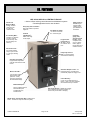
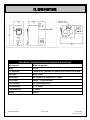
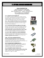
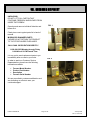
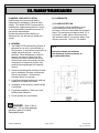
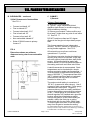
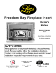
MODEL 521FB WOOD-BURNING FURNACE MANUAL Manufactured in the U.S.A. by DAKA CORPORATION 955 Industrial Street NE Pine City, Minnesota 55063 Phone: 320-629-6737 Fax: 320-629-3677 www.dakacorp.com DAKA 521FB Manual Page 1 of 32 January 2009 Rev. 3, June 2013 I. LIMITED WARRANTY This furnace meets U.S. Test Standard: UL 391-2010 – MARCH 2010 AND SEPT. 2010 This model has been tested and listed in accordance with Underwriters Laboratories Standard UL 391-2010 – March 2010 and Sept. 2010 for Solid Fuel Central and Supplementary Furnace by Intertek Testing Services/Warnock Hersey Inc. International Conference of Building Officials (ICBO) Report No. TL116 Council of American Building Officials (CABO) Report No. NER QA219 Purchase Date: SAVE THESE INSTRUCTIONS. Purchased From: Model #: Serial #: DAKA Corporation warrants the combustion chambers of its supplementary and central furnaces to be free of defects in material or workmanship for five years (non-prorated) from date of sale. All other components, including electronics, gaskets and grates, are covered in the same manner for a period of one year. DAKA Corporation will repair or replace defective components, at our option, at no charge for parts and labor, and will pay freight charge for one-way shipment for warranty claims during the first year. In second and subsequent years, only parts and labor will be provided at no charge. DAKA Corporation is not responsible for installation or dismantling costs. The warranty is void if unit is not used in a residential service connected to conventional basement-type upflow central heating system, if non-approved fuels are used in firing of units, or if unit is damaged due to accident, improper installation or negligence. For service under this warranty, contact selling dealer or DAKA Corporation, Customer Service Dept., 955 Industrial St. NE, Pine City, MN 55063; telephone 320-629-6737 or email [email protected]. Implied warranties including that of merchantability are expressly limited in duration to the duration of this warranty. DAKA Corporation disclaims any responsibility for consequential damages. Some states do not allow limitations on how long an implied warranty lasts, or the exclusion or limitation of incidental or consequential damages, so this limitation and exclusion may not apply to you. This warranty gives you specific legal rights and you also may have other rights that vary from state to state. This is our exclusive written warranty. DAKA 521FB Manual Page 2 of 32 January 2009 Rev. 3, June 2013 II. TABLE OF CONTENTS DAKA 521FB WOOD-BURNING FURNACE MANUAL I. II. III. IV. V. VI. VII. VIII. IX. X. XI. XII. XIII. XIV. LIMITED WARRANTY .................................................................................................. 2 TABLE OF CONTENTS ............................................................................................... 3 FEATURES .................................................................................................................. 4 SPECIFICATIONS........................................................................................................ 5 OPTIONAL FURNACE ACCESSORIES ...................................................................... 6 GENERAL WOOD-BURNING SAFETY ................................................................... 7, 8 CHECKING SHIPMENT ............................................................................................... 9 PLANNING YOUR INSTALLATION ...................................................................... 10-14 A. General B. Clearances C. Chimney D. Supplementary/Add-on E. Central ASSEMBLY INSTRUCTIONS ............................................................................... 15-20 A. Components (Main) B. Electrical components (Fan Control, Wiring) C. Cold Air Return Filter Box INSTALLATION ..................................................................................................... 21-25 A. Connecting to Ductwork 1. Supplementary/Add-On 2. Central 3. Alternative Connection Options B. Connecting to Chimney OPERATING INSTRUCTIONS............................................................................. 26, 27 A. General B. Operating Controls: Snap Disc Fan Control & Automatic Damper Control C. Emergency MAINTENANCE INSTRUCTIONS .............................................................................. 28 TROUBLESHOOTING ............................................................................................... 29 PARTS LIST & EXPLODED VIEW ............................................................................. 30 DAKA 521FB Manual Page 3 of 32 January 2009 Rev. 3, June 2013 III. FEATURES 2 Sides and Back Fire Brick Lining – Durable construction for long life and consistent heat. UL Tested by WHI – Tested to UL Standard 391-2010 – March 2010 and Sept. 2010. Ensures safety and efficiency. USE AS AN ADD-ON or CENTRAL FURNACE – Add-on utilizes existing central ductwork and distribution system – Central application has its own ductwork. Heavy Duty Cast Iron Grates – High heat resistance provides longer life. 2-8” Warm Air Outlets – for secure connection of 8” round duct pipe. 42,000 to 105,000 BTU’s – Offers wide range of heat output. Large Fire Box holds 90 lbs. of 22” logs – Allows for maximum burn time. 8 Hour Burn Time – For average heating output, up to 12 hours of “overnight” heating needs. Heats Homes up to 2,600 sq. ft. – Largest heating capacity for the price available in the market. Complete 7 gauge (3/16”) steel throughout Firebox – Most competitors offer only a 10-gauge firebox; approx. half the strength of a DAKA Furnace. Heavy Duty Cast Iron Door – Prevents warping and maximizes efficiency. Snap Disc Thermostat – A highly reliable independent snap disc thermostat controls blower. Automatic Damper Control – For maintenance free, consistent heat; automatically adjusts air supply to fire. Blower, 550 CFM – 1/10 HP helps maintain CFM at higher static pressures. Totally enclosed, permanently lubricated ball-bearings. 5-Year Warranty – 5-year non-prorated warranty on firebox; 1 year on all other materials. See Written Warranty for details. Backdraft Damper – Factory-installed warm air back draft damper is included with every 521FB furnace. Full Length Ash Pan – Makes ash handling more convenient and reduces spillage; no back on ash pan for ease of dumping. NOTE: Return Cold Air Filter Box included but not shown. The filter box improves indoor air quality. DAKA 521FB Manual Page 4 of 32 January 2009 Rev. 3, June 2013 IV. SPECIFICATIONS DAKA MODEL 521FB WOOD-BURNING FURNACE SPECIFICATIONS Manufacturer: DAKA Corporation Model: 521FB U.L. Approval: Tested to U.L. Standard 391–March 2010 & Sept. 2010 by WHI Fuel Type: Wood / Coal Dimensions: 44” Height x 24” Width x 25-½” Depth BTU Output: 42,000 – 105,000 per hour Fuel Capacity: 22” Log Length / 90 lb. Air Outlet Size: 2 – 8” round Flue Outlet Size: 6” round Weight: 432 lbs. DAKA 521FB Manual Page 5 of 32 January 2009 Rev. 3, June 2013 V. OPTIONAL FURNACE ACCESSORIES DAKA CORPORATION 955 Industrial St NE, Pine City MN 55063 Telephone: 320-629-6737 Fax: 320-629-3677 Email: [email protected] Website: www.dakacorp.com Visit our website or call 1-800-884-3252 for pricing and shipping information. 273 - TWIN 550-CFM BLOWER KIT For installations requiring additional air pressure, such as for use as a central furnace. Kit includes one 550-cfm splitcapacitor blower, wiring and instructions. For use with models 521FB/621/622, many earlier deluxe models. 258 – DUAL BLOWER RETURN COLD AIR FILTER BOX With No. 273 twin blower kit installed, this galvanized filter box covers both blowers. Takes one 14" x 25 x 1” paper furnace filter (not included.). 218 - LARGE MULTI-SPEED BLOWER & FILTER BOX Mounts on side of furnace to provide increased air delivery for higher static pressure central furnace applications. Kit includes a direct drive 1/3 HP motor with multi speeds (select speed based on wiring configuration), squirrel cage & housing assembly, galvanized sheet metal cold air return filter box, mounting hardware & assembly instructions. 223 - HOT-TUBE™ DOMESTIC HOT WATER PREHEATER Connects to present domestic hot water tank to provide gallons of piping hot water. Weldless boiler pipe has working pressure of 1200lbs./sq. in. Kit includes pre-heater pipe, hardware, gaskets and instructions. 238D - SOFT COAL SHAKER GRATE KIT Replaces wood-burning grate to permit burning of bituminous and sub-bituminous coal in Deluxe models ` 311/411/521FB/621/622 above, many earlier models. Includes extra -thick 3-section shaker grates and shaker rod assembly & fire door with spinner knob. 253 - FORCED DRAFT CONVERSION KIT Adds convenience of living area control of heat output of Deluxe models 521FB and 621, many earlier models. Kit includes 35-cfm draft blower, wall thermostat, transformer/relay, controls, wiring and instructions. 283 - BAROMETRIC DRAFT REGULATOR Installs in chimney connector to help provide constant draft control, extend burn times, save fuel, avoid over-firing, and reduce creosote formation. Adjustable from .02" to .08" updraft. For 6" pipe. U.L. Listed. DAKA 521FB Manual Page 6 of 32 January 2009 Rev. 3, June 2013 VI. GENERAL WOOD-BURNING SAFETY STOP FOR SAFETY! Safe assembly, operating and maintenance practices should always be followed whenever using any equipment. READ THROUGH THE ENTIRE MANUAL BEFORE BEGINNING YOUR INSTALLATION OR OPERATING YOUR FURNACE. FOLLOW ALL STEPS EXACTLY! WARNING: Disconnect all power before making electrical connection. For power supply connections, use No. 14 AWG or larger wires acceptable for at least 105C. Check local codes for acceptable components. WARNING: Do not over fire the furnace. Over firing will happen if the fire door or ash door is left open during operation. Such actions can result in very dangerous operating conditions. WARNING – Risk of fire! Do not operate with flue draft exceeding .06” WC. (measured in water column). Use of a draft gauge is highly recommended. Follow gauge manufacturer’s instructions. Gauges to measure chimney draft are readily available at furnace shops and are economical to purchase or rent. If a draft gauge is not available, with the draft regulator fully installed and a good fire burning, adjust the counterbalance weight closer to the gate for as low a draft setting as possible, without the fire dying or getting smokeback with the stove door slightly open. To obtain higher heat levels, move the weight away from the gate to increase the setting. WARNING: Do not operate with fuel loading or ash removal doors open. Do not store fuel or other combustible material within marked installation clearances. Inspect and clean flues and chimney regularly. WARNING: For further information on using your furnace safely, contact the National Fire Protection Association (NFPA) at www.nfpa.org. WARNING: To prevent burns, always wear protective clothing, leather hearth gloves and eye protection, while tending the fire. WARNING: While in operation, keep the fire door and ash door closed at all times except while tending the fire. WARNING: Burn wood only or burn coal only. CAUTION: Hot Surfaces! Keep children away. Do not touch during operation. Maintain clearance to combustibles as listed on nameplate. Refer to product nameplate and manual for additional information. CAUTION: During a power failure, set auto damper no higher than EPF setting. Remove furnace air filter. Air jacket top and sides may be removed to keep the firebox from overheating. DO NOT expect the furnace to keep the house as warm as when power is on. Do not attempt to increase heat output by opening ash door or fire door. CAUTION: Turn off all power to furnace before cleaning. WARNING: Do not operate furnace while under the influence of drugs or alcohol. DAKA 521FB Manual Page 7 of 32 January 2009 Rev. 3, June 2013 VI. GENERAL WOOD-BURNING SAFETY Building Codes: Check local building and mechanical codes prior to installation to ensure conformance with all requirements. Home Insurance: Review home insurance policy for coverage. Paint Odor: During initial start-up, the unit may omit fumes as the paint outside shell cures. Please provide outside ventilation throughout the home to help clear the odor. Ash Disposal: Ashes should be placed in a metal container with a tight-fitting lid. The closed container of ashes should be placed on a non-combustible floor or on the ground – well away from all combustible materials pending final disposal. The ashes may be disposed of by burial in the soil or otherwise locally dispersed. They should be retained in the closed container until all cinders have thoroughly cooled. Creosote: Formation & Need for Removal When wood is burned slowly, it produces tar and other organic vapors that combine with expelled moisture to form creosote. The creosote vapors condense in the relatively cool chimney flue of a slowburning fire. As a result, creosote residue accumulates on the flue lining. When ignited, this creosote makes an extremely hot fire. The chimney connector and chimney should be inspected at least twice monthly during the heating season to determine if a creosote buildup has occurred. If creosote has accumulated, it should be removed to reduce the risk of a chimney fire. SAFETY NOTICE IF THIS FURNACE IS NOT PROPERLY INSTALLED, A HOUSE/BUILDING FIRE MAY RESULT. FOR YOUR SAFETY, CONTACT LOCAL BUILDING OR FIRE OFFICIALS ABOUT PERMITS, RESTRICTIONS AND INSTALLATION REQUIREMENTS FOR YOUR AREA. REFER TO MARKING ON APPLIANCE FOR ADDITIONAL INFORMATION. DAKA 521FB Manual Page 8 of 32 January 2009 Rev. 3, June 2013 VII. CHECKING SHIPMENT UNPACKING DO NOT LIFT FULL CARTON THAT CONTAINS FIREBRICK AND BLOWER FROM INSIDE THE FIREBOX. FIG. 1 Open box and remove individual firebricks and blower first. Check piece count against parts list in back of manual. MISSING OR DAMAGED PARTS PLEASE DO NOT RETURN THE PRODUCT TO THE STORE WHERE PURCHASED. CALL DAKA CORPORATION DIRECTLY. 1-800-884-3252 Monday through Friday 8:00 AM to 4:30 PM Central Time It is our goal to send replacement parts to you immediately after we receive your order. FIG. 2 In order to assist our Customer Service Representative, please have the following information available. Furnace Model Number Product Part Number Description Furnace Serial Number We are committed to customer satisfaction and are dedicating our efforts to earn your continued support. DAKA 521FB Manual Page 9 of 32 January 2009 Rev. 3, June 2013 VIII. PLANNING YOUR INSTALLATION PLANNING YOUR INSTALLATION Read through the entire manual before beginning your installation. Follow all steps exactly. Your Model 521FB Furnace can be installed as a supplementary/Add-on Furnace or as a free-standing central furnace with its own plenum and ductwork. Review the location options below and determine how you are going to install your system. B. CLEARANCES 1) FLOOR PROTECTION 1. This furnace must be installed on a noncombustible floor surface such as solid concrete or 3/8” non-combustible floor protector board. This surface must extend at least 16” in front and 8” to both sides of the furnace and also extend at least 2” out from the sides of the chimney connector. See FIG. 3 for details. A. GENERAL 1. The DAKA 521FB wood-burning furnace is designed for use only in conventional up flow systems. It must deliver heated air to a supply (warm air) plenum – never to ductwork. When installed as an Add-On furnace, the warm air supply from this furnace must never be connected to the cold-air return inlet of the primary furnace; components of the primary furnace may overheat causing damage to the primary furnace. FIG. 3 Dimensions shown are minimum clear distances for floor protector or non-combustible floor. 2. Check local building and mechanical codes prior to installation to insure conformance with all requirements. Review home insurance policy for coverage. 3. A qualified individual familiar with solid-fuel systems must install this furnace. 4. Installation of this furnace in mobile homes is prohibited. 5. For garage installation, check your local building code ordinance. 6. Do not operate as a room heater. DANGER – Risk of fire or explosion – Do not burn garbage, gasoline, drain oil or other flammable liquids. DAKA 521FB Manual Page 10 of 32 January 2009 Rev. 3, June 2013 VIII. PLANNING YOUR INSTALLATION B. CLEARANCES – continued 2) Wall Clearances to Combustibles See FIG. 4. C. CHIMNEY 1) General Chimney Requirements: 1) Minimum 6” inside diameter 2) “Type HT” (High Temperature)-listed appliance-type chimney or a code-complying tile-lined masonry chimney. 3) Chimney must extend 3’ above roofline and be at least 2’ higher than any point of roof within 10’. See FIG. 5. Furnace to sidewall: 18” Flue to sidewall: 27” Furnace to back wall: 32 ½” Flue to back wall: 23” Furnace to front wall: 48” Non-combustible sidewall: 6” Sides of DAKA furnace to primary furnace: 9” DO NOT install more than two 90° degree elbows in the flue pipe to help maintain proper draft. This furnace requires its own independent chimney. DO NOT connect to a chimney flue serving another appliance. See FIG. 6. FIG. 4 Dimensions shown are minimum distances to stay clear from combustible walls. All horizontal runs must have a minimum upward rise of ¼” per foot. The chimney connector (smoke pipe leading to chimney flue) must be of minimum 24-ga. pipe with each section joined with three sheet metal screws. All fissures should be sealed with furnace cement. Do not use galvanized pipe as the coating could melt and cause toxic fumes. A stack thermometer is recommended. Stack temperatures can be checked with a simple surface-mounted or probe-type thermometer. It is recommended to maintain normal operating range of 300-600 ° F. Temperatures lower than 300° F indicate insufficient draft or inadequate combustion air and may result in creosote formation in chimney flue. The maximum draft setting is a maximum of .06” W.C. (measured in water column). Use of a gauge is highly recommended. Follow gauge manufacturer’s instructions. Gauges to measure chimney draft are readily available at furnace shops and are economical to purchase or rent. If a draft gauge is not available, with the draft regulator fully installed and a good fire burning, adjust the counterbalance weight closer to the gate for as low a draft setting as possible, without the fire dying or getting smoke-back with the stove door slightly open. To obtain higher heat levels, move the weight away from the gate to increase the setting. [An optional DAKA barometric regulator #283 may be used in the chimney connector to help increase furnace efficiency by maintaining a consistent draft. See FIGS. 5 & 6 on page 12.] DAKA 521FB Manual Page 11 of 32 January 2009 Rev. 3, June 2013 VIII. PLANNING YOUR INSTALLATION C. CHIMNEY – continued FIG. 5 2) Chimney Options a) Masonry – Before using an existing masonry chimney, have the chimney inspected, cleaned and make all necessary repairs before attaching the furnace. The flue pipe and fittings you will need to connect your furnace directly to a masonry chimney are shown in FIG. 5. If the flue pipe must go through a combustible wall or ceiling before entering the masonry chimney, consult a qualified mason or chimney dealer. The installation must conform to all local building and fire codes and the latest edition of the National Association of Fire Protection (NFPA) Publication 211. If there is a cleanout in the base of the chimney, close it tightly. The chimney flue pipe must not pass through an attic or roof space, closet, or any concealed space, or floor, ceiling, wall or combustible construction. See FIG. 5. b) Factory Built – Factory built chimneys are generally stainless steel, insulated, multi-wall pipes. Chimney must be listed to UL103 and carry a rating of “HT” (High Temperature). The top of the chimney must be at least three 3 feet above the roof and be at least two 2 feet higher than any point of the roof within ten feet – See FIG. 6. A factory-built chimney must be installed to the manufacturer’s specs. FIG. 6 If you have any questions regarding venting your furnace, request a copy of the National Fire Protection Association’s (NFPA) Publication 211 [Standard for Chimneys, Fireplaces, Vents & Solid Fuel-based Appliances]. National Fire Protection Association 1 Battery March Park, Quincy MA 02169-7471, 1-617-770-3000 or online at www.nfpa.org. NOTE: This furnace must be connected to a minimum 6” listed Type HT (High Temp) appliance-type chimney or a code-compliant tile-lined masonry chimney. Connection to a chimney flue serving another appliance is prohibited. DAKA 521FB Manual Page 12 of 32 January 2009 Rev. 3, June 2013 VIII. PLANNING YOUR INSTALLATION GENERAL INFORMATION This furnace model is designed for a conventional up flow residential central force air heating system. It may be installed as a SUPPLEMENTARY/ADD-ON or CENTRAL FURNACE APPLICATION. It is designed to operate with a maximum warm air duct pressure of 0.2” water column and a maximum warm air duct temperature of 250° degrees F. The warm air supply duct system must be constructed of materials with a minimum temperature rating of 250° degrees F. Plenums installed to the furnace must be constructed of metal. Do not use flexible pipe. IMPORTANT: WHETHER INSTALLED AS A SUPPLEMENTARY/ADD-ON OR CENTRAL FURNACE, INSTALLATION OF A COLD AIR RETURN LINE IS MANDATORY. NOTE: Any time you increase the air flow, we recommend that you increase the size of the outlets and the cold air return line. D. SUPPLEMENTARY/ADD-ON FURNACE APPLICATION When installed as a Supplementary/Add-On furnace, this DAKA furnace model is designed to work in conjunction with a conventional up flow residential central forced air heating system. See FIG. 7. Air can be provided to the DAKA furnace through the same cold air return line that is used by the primary furnace. This will require installation of an air line between the cold air filter box and the cold air return line of the primary furnace. NOTE: When used as a Supplementary/Add-On furnace, confirm that your primary furnace is capable of running at an external static pressure greater than 0.2” W.C. This information should be found on the primary furnace nameplate. It can be connected in parallel to a conventional primary furnace system. Using present ductwork, the DAKA supplementary furnace system & blower lifts the warm air from the wood-burning furnace into the plenum of the primary furnace for distribution by the primary furnace blower. The heat produced by the wood-burning furnace should be able to keep the room temperature above that of the setting of the primary furnace wall thermostat. This will keep the primary furnace from burning any gas, oil, or electricity beyond what is required to run the primary distribution blower. Should the wood fire fail to provide sufficient heat, the primary furnace will begin operating as usual. When used as a supplementary/Add-On furnace, a fixed back-draft damper may be required in the 8” warm duct pipes from the DAKA furnace. They also may be needed in the plenum of the existing primary furnace. Installation of these back-draft dampers is to prevent overheating. We recommend that once the units are operating that both units be monitored to make sure that neither is overheating. FIG. 7 Supplementary/ Add-On Installation DAKA 521FB Manual Page 13 of 32 January 2009 Rev. 3, June 2013 VIII. PLANNING YOUR INSTALLATION E. CENTRAL FURNACE APPLICATION When installed with its own plenum and ductwork, the furnace will operate as a freestanding Central furnace. See FIG. 8. The 550-cfm blower provided is often sufficient to provide air distribution for smaller homes with short duct runs. A second optional 550-cfm blower (DAKA #273), or a large side-mounted multi-speed blower & filter box (DAKA #218), may be required for larger homes with longer ductwork (available online at www.dakacorp.com). CAUTION: DO NOT USE AS A FREE-STANDING RADIANT HEATER. NOTE: A cold air return line must be installed between the cold air return filter box and the rooms being serviced by the warm air outputs of the DAKA furnace. FIG. 8 DAKA 521FB Manual Page 14 of 32 January 2009 Rev. 3, June 2013 IX. ASSEMBLY INSTRUCTIONS FIG. 9 INSTALL FIRE DOOR 1. Attach fire door hinge to front of furnace. See FIG. 9. Position hinge against furnace with hinge pinhole closest to door opening. When viewing hinge bracket from top, make sure that the notched corner is facing away from door opening. 2. Insert two ¼” hex bolts through hinge bracket and holes located just to the right of the door opening. Place washer and nut on bolt from INSIDE furnace. NOTE: ¼” nut that is used is a lock-nut and will require that you use an open-end wrench to hold the nut while turning the bolt with socket driver on exterior. Center bolts in slotted holes to start with. Tighten bolts enough to hold bracket in place with fire door installed. 3. Install fire door onto hinge bracket. See FIG. 10. Insert hinge pin from top down. NOTE: Rotate door handle counterclockwise to secure door in the closed position. 4. With fire door installed, check fire door for proper fit – doorframe should hit center of rope gasket. If door doesn’t fit properly (e.g., cast iron door hits door frame rather than gasket), note location of problem and then remove fire door. With fire door removed, adjust hinge bracket location. The holes in the hinge bracket are slotted vertically for up and down adjustment. The holes in the furnace are slotted horizontally for left to right adjustment. Once the proper placement has been found, tighten bolts securely to prevent hinge from moving. FIG. 10 INSTALL ASH PAN & ASH DOOR 1. Insert thermal gasket between Fire door ash door and ash pan front, making sure that silver foil side of gasket is facing INWARD toward ash pan. 2. Securely attach ash door to ash pan using two (2) ¼” bolts and nuts provided. See FIG. 11. NOTE: Ash pan is open-ended scoop design for easy emptying of ash pan. FIG. 11 Fire Door Ash Pan DAKA 521FB Manual Page 15 of 32 January 2009 Rev. 3, June 2013 IX. ASSEMBLY INSTRUCTIONS INSTALL FIRE BRICK With everything removed from inside firebox, install firebrick. 1. To install firebrick, hold firebrick in standing position and angle top of firebrick toward outside wall. Slip top edge of firebrick under retaining angle. Stand firebrick up so bottom of brick sits evenly on support rail. 2. Center rear firebrick (3) across back of firebox. Insert sidewall firebrick (5 ea) at front of furnace. As more are inserted, push brick as far back as possible towards rear of furnace. NOTE: There will be a small gap in each back corner. This is normal and will not adversely affect operation. INSTALL AUTOMATIC DAMPER CONTROL Remove Automatic Damper Control from protective wrapping. Remove ¼” bolt and ¼” nut that were installed in one corner of damper control for shipping purposes only. Attach Automatic Damper Control assembly to front of furnace below the fire door opening with six (6) No. 12 x ½” screws. Install top corner screws first. Do not completely tighten until all six screws have been inserted into holes. NOTE: To ease installation of screws, use one drop of motor oil on each screw before installing. Use a 5/16” nut driver or a 5/16” socket to install screws. TIGHTEN FIRMLY. See FIG. 13. FIG. 13 INSTALL CAST IRON GRATE With reinforcement ribs facing down, insert grate through fire door opening. Grate must be held at a 45° degree angle as shown in FIG. 12. Place one side edge down on support rail. Drop other side down. Grate should lie flat on both side support rails. Auto Damper Control FIG. 12 Auto Damper Cast Iron Grate Grate FIG. DAKA 521FB Manual Page 16 of 32 January 2009 Rev. 3, June 2013 IX. ASSEMBLY INSTRUCTIONS INSTALL BLOWER FIG. 14 NOTE: For Add-On furnace installation, do NOT remove the back-draft damper plate. For Central Furnace installation, back-draft damper plate may be removed. (It is located inside the blower inlet on the right hand side of back of furnace. Break wire nut to remove). Blower Install 550-cfm blower over inlet on right hand side of back of furnace using four (4) No. 12 x ½” screws. See FIG. 14. CAUTION: Handle blower by the housing unit. DO NOT REACH INSIDE IMPELLER CAVITY. INSTALL AIR JACKET PANELS Furnace is shipped with air jacket panels installed. If loose or removed during installation, re-install as follows: FIG. 15 1. Install bottom edge of side panel into channel on bottom support rail. Working from the bottom up, press side panel tightly against firebox. See FIG. 15. 2. Install top air jacket from back to front making sure air jacket lip goes OVER the outside of side panels (shoebox style fit). NOTE: To ease top over sides, insert a putty knife under top lip and pry lip outward over side panel. See FIG. 17. INSTALL SWING PLATE Open fire door and carefully feel for two (2) steel hooks above door opening. With bent edge facing inward, hang swing plate from hooks. See FIG. 15. DAKA 521FB Manual Page 17 of 32 January 2009 Rev. 3, June 2013 IX. ASSEMBLY INSTRUCTIONS MOUNT JUNCTION BOX, INSTALL FAN CONTROL, INSTALL CONDUIT WITH PRE-RUN WIRES, & WIRING INSTALL FAN CONTROL ASSEMBLY FIG. 16 Junction Box and Conduit (FIG. 16): 1. Remove cover plate from junction box. 2. Mount junction box using two (2) No. 12 x ½” screws onto left side of furnace in outer pre-punched holes. NOTE: Screws go in upper left and bottom right slotted corners. 3. Remove one knockout plug from bottom and one knockout plug from top or from whichever side your power supply will be entering. 4. Place a conduit connector on each end of the flexible conduit. 5. Insert one connector in the bottom hole of the junction box located on side of furnace. 6. Attach the other connector to the junction box on blower motor. Junction Box & Cover Snap Disc Fan Control: (FIG. 17) 1. Mount Snap Disc Fan Control using two (2) No. 12 x ½” screws onto left side of furnace in inner pre-punched holes located within the junction box. FIG. 17 Outside Wiring NOTE: Make sure Fan Control is flush against furnace air jacket panel. DAKA 521FB Manual Page 18 of 32 January 2009 Rev. 3, June 2013 IX. ASSEMBLY INSTRUCTIONS WIRING INSTRUCTIONS FIG. 18 WARNING: Disconnect all power before making electrical connection. Power Supply Connections 1. Using an approved conduit and connector, bring a 3-wire 120V AC 15-amp minimum electrical service to the Junction Box. 2. Use minimum No. 14 AWG or larger wires, rated for at least 105C (not provided). NOTE: Power connections should be made by a qualified installer to comply with The National Fire Protection Association (NFPA) Standard No. 70 (National Electric Code) and all local codes and regulations. Blower Junction Box Wiring: 1. Inside the blower junction box, connect wires with two blue wire nuts as follows: a) Black wire to one blue wire; b) White wire to other blue wire. Blower motor operates in one direction only & is not reversible. 2. Tuck the wires into blower junction box. 3. Replace blower junction box cover. Fan Control Wiring: 1. Attach one of the crimp terminals to black (hot) power supply wire. 2. Attach the other crimp terminal to one end of one blue wire coming from blower. 3. Attach the two crimp terminals to each side of the Snap Disc Fan Control. 4. Connect other blue wire to white wire supplying power to the unit. 5. Connect green ground wires together. 6. Check all connections for tightness and electrical safety. 7. Coil all wires within junction box. 8. Install 4” square Junction box cover plate. DAKA 521FB Manual Page 19 of 32 January 2009 Rev. 3, June 2013 IX. ASSEMBLY INSTRUCTIONS COLD AIR RETURN FILTER BOX ASSEMBLY & INSTALLATION 1. Using the sheet metal screws provided (Key 6) first attach the bottom panel (Key 2) to side panel A (Key 3) 2. Next, attach side panel B (Key 4) and side panel C (Key 5) to bottom panel (Key 2). 3. With blower and wiring already installed on DAKA furnace, the next step is to loosen, but not remove, all four screws holding the fan hole cover plate. (See FIG. 2). 4. Remove air jacket top and right side air jacket panel from DAKA furnace. 5. Take the partially assembled filter box and slide it into position. Once in position, slide outer flange on panel A (Key 3) under the fan hole cover plate. Retighten the four screws holding the fan hole cover plate. Once these screws are tightened, they will hold the left side of the filter box in position. 6. Install top panel of filter box to all side panels. 7. Reinstall right air jacket side panel, making sure back edge of air jacket panel overlaps outer flange on panel C. Once air jacket side panel is in position, it will hold the right side of the filter box in position. 8. Place air jacket top back onto DAKA furnace. 9. INSTALLATION OF A COLD AIR RETURN LINE IS MANDATORY: − Minimum size is 13” x 13” or 170 square inches. 10. Furnace Filter: Size 14 x 20 x 1 fiberglass filter (side may be cut to fit width of filter box). DAKA 521FB Manual Page 20 of 32 January 2009 Rev. 3, June 2013 X. INSTALLATION A.1. CONNECTING TO DUCTWORK (SUPPLEMENTARY/ADD-ON) IMPORTANT: Installation of a cold air return line to the DAKA furnace is mandatory. (EXAMPLE) FIG. 19 FIG. 20 (See other options on page 23) IMPORTANT: The plenums installed to the furnaces must be of metal construction. Verify beforehand that sufficient clearance is available above air conditioner coil, etc. If sufficient clearance is not available, air conditioner coil may have to be moved to a second plenum with diversion baffles for summer use. The 90° degree elbow within the supply plenum forms a venturi. This is used to extract air from the DAKA furnace when the primary furnace blower comes on. The absence of this elbow will cause back pressure down the warm air pipe to the DAKA furnace. This will adversely affect the heat distribution and possibly damage the DAKA furnace. If space prohibits installation of 90° degree elbow as recommended, look for alternate designs shown in FIG. 20 or on Page 23. (Continued on page 22.) DAKA 521FB Manual Page 21 of 32 January 2009 Rev. 3, June 2013 X. INSTALLATION IMPORTANT: In a Supplementary/Add-on installation, the blower on the DAKA furnace is not used as a circulation blower for heating the house, but as a lift blower to get the heat into the supply plenum. From there, the primary blower will turn on as heat is received from the DAKA furnace. A fan control will have to be installed, wiring it in parallel with the primary blower fan control at the heat exchanger level. See next page for necessary position of this fan control. NOTE: After attaching warm and cold air supply and return pipes to the primary furnace, check the entire system to insure that static pressure remains unaffected. Verify horizontal duct clearances. A.2. CONNECTING TO DUCTWORK (WHEN USED AS CENTRAL FURNACE) IMPORTANT: Installation of a cold air return line to the DAKA furnace is mandatory. 1. Install a minimum 13” x 20” plenum on air jacket top. You may want to cut top with tin snips or saber saw to help free up the air flow out of the DAKA furnace. 2. Install ductwork with proper clearances to combustibles in accordance with local building codes. 3. Connect cold air return to No. 260 filter box provided. A twin blower conversion kit No. 273 is available to increase airflow to 1100-cfm where necessary. This will provide for better heat distribution. NOTE: The No. 273 twin blower conversion kit requires a No. 258 dual blower cold air return filter box. Both are available online at www.dakacor.com. IMPORTANT: The plenums installed to the furnaces must be of metal construction. DAKA 521FB Manual Page 22 of 32 January 2009 Rev. 3, June 2013 X. INSTALLATION A3. ALTERNATIVE CONNECTION OPTIONS DAKA 521FB Manual Page 23 of 32 January 2009 Rev. 3, June 2013 X. INSTALLATION B. CONNECTING TO CHIMNEY Mount and secure 6” non-galvanized smoke pipe, 24-ga. or heavier, to rear smoke outlet collar on DAKA furnace. The collar is sized so that the crimped end of a standard 6” stove pipe will fit inside collar. Continue same gauge single-wall pipe to chimney connection. At chimney connection, use a double-crimped end stove pipe adapter to connect to chimney. Smoke pipe should normally be installed with crimped ends leading from chimney to furnace. Should runny creosote be formed in chimney connector, it will then return through pipe to furnace without dripping out of joints. INSTALL BAROMETRIC REGULATOR A barometric regulator should be installed in smoke pipe at least 18” from furnace. This will permit adjustment of chimney draft to a maximum of .06’ water column draft. Barometric Regulator No. 283 with adjustable draft setting is available through DAKA dealers or direct from the factory for this purpose. See FIG. 21. NOTE: During initial start-up, the unit may omit fumes as the paint on the outside shell cures. Please provide outside ventilation through the home to help clear the odor. Heat reclaimers, fins or the like should not be used on smoke pipe as they tend to cool flue gases and add to creosote formation on stoves and furnaces of advanced airtight design. Adequate combustion air must be provided in furnace area to prevent poor firing and poor draft. Keep a window cracked open in furnace area or install dryer-type 4” vent to bring in outside fresh air. FIG. 21 Chimney Barometric Regulator Smoke Pipe Single wall smoke pipe must maintain a minimum 18” clearance to all combustibles and must never pass through walls or ceilings. Use proper thimbles for those passages. All joints of chimney connector pipe should be secured with a minimum of three No. 7 sheet metal screws and further sealed with furnace cement to maintain good draft. Maintain a minimum of ¼” per foot of pipe rise to chimney connection. The steeper the rise, the more easily draft will be maintained, generally. Limit the use of 90°elbows in any chimney connector as they adversely affect draft. If 90° elbows must be used, do not install more than two in any chimney connector. DAKA 521FB Manual Page 24 of 32 January 2009 Rev. 3, June 2013 X. INSTALLATION B. CONNECTING TO CHIMNEY (cont’d) DAKA 521FB Manual Page 25 of 32 January 2009 Rev. 3, June 2013 XI. OPERATING INSTRUCTIONS FUEL TYPES Burn wood only or burn coal only. Do not burn garbage, flammable fluids, drain oil, wood chips or any other non-approved items. Wood should be cut & split and seasoned for at least 6 months. FUELING PROCEDURE Start fires by first taking single sheets of newspaper and rolling them tight. Lay them on the grate. Place finely-split kindling on top of newspaper. much heat to keep the house warm. Remember to build fires using less wood and continue to run the damper at a higher setting vs. over-filling the firebox and turning the damper down. This may require more frequent tending of the fire, but will result in a cleaner and safer fire. If running the furnace at higher setting results in too much heat generation, i.e., “over-heating the house,” the best thing to do is reduce the amount of wood used. Open ash door about 1” and turn auto damper to “High.” Place one more sheet of paper on top of shelf baffle inside furnace. Light this sheet first and let it burn completely out before lighting paper underneath kindling. NOTE: Burning the newspaper on top of baffle first helps pre-heat the flue and gets the draft working. An inexpensive magnetic thermostat located on the flue pipe is a great way to tell what temperature you are burning at. Flue pipe temperatures in the range of 300°-600° are recommended. Creosote is formed at temps lower than 300°. With the kindling burning, proceed to add several larger pieces of cord wood. DO NOT FILL ABOVE THE TOP OF THE FIREBRICK. Snap Disc Fan Control The snap disc fan control (mounted in the J-box extension ring on the side of the DAKA furnace) is designed to turn on the 550-cfm lift blower on the DAKA furnace whenever the air temperature within the air jacket exceeds 120F. It should turn it off whenever the air jacket temperature falls below 100F. This range is built into the snap disc thermostat and cannot be adjusted. OPERATING CONTROLS With the fire now burning, make sure to close the ash door tightly and turn the auto damper to appropriate setting for your heating needs. Attend to fire as often as possible and add wood as needed. FIRE CHAMBER AND ASH PAN Check ash pan every few days and safely dispose of ashes. Keep ashes from building up on grate and interfering with combustion airflow from below. AIR FILTER (14 x 20 x 1) Check weekly and change as necessary. FLUE PIPE AND CHIMNEY A visual inspection of the flue pipe and chimney is recommended once a week for the first month and once a month thereafter. IMPORTANT: In a supplementary/“add-on” installation, the blower on the DAKA furnace is not used as a circulation blower for heating the house. It is used as a lift blower to get the heat into the supply plenum of the primary furnace. If your primary furnace is not equipped with a fan control in the supply plenum to turn on the primary blower as heat is received from the DAKA furnace, one will have to be installed. It will need to be wired in parallel with the primary blower fan control at the heat exchanger level. See Installation Section, page 23, for necessary position of this fan control. Most problems associated with creosote are seen in the fall and spring times of the year. It is at this time when most people do not need DAKA 521FB Manual Page 26 of 32 January 2009 Rev. 3, June 2013 XI. OPERATING INSTRUCTIONS OPERATING CONTROLS – continued Automatic Damper Control (ADC) The Automatic Damper Control (ADC) controls Fresh air to fire Heat output Burn time Amount of fuel burned Efficiency Stack temperature. By understanding how simple adjustments to the ADC will affect the output of the furnace you will be better able to obtain the results you are looking for. There are two things that you can control with any wood burning appliance: 1) The amount of available fuel and 2) the rate at which the furnace burns fuel. All other things are bi-products of that combination. FIRE CHAMBER AND ASH PAN Check ash pan every few days and safely dispose of ashes. Keep ashes from building up on grate and interfering with combustion airflow from below. At end of heating season, clean out all residual ashes & soot from furnace. The moisture they contain could rust your furnace over the summer months & shorten the life of the unit. EMERGENCY OPERATION You control the amount of fuel every time you refuel the fire. The fuel burn rate is controlled by how much air the fire is allowed to have. For example, a full load of wood can be burned in as little as 4 hours, or can last up to 8 hours or more, by simple limiting the amount of air to the fire. In cold weather, your home will require more heat, which means you will most likely burn more wood because you will need to supply the fire with more air and more fuel. More air is supplied by simply adjusting the ADC to a higher setting and more fuel is supplied by refueling the fire more frequently. The higher the heat output the shorter the time between refueling. Maximum heat output and maximum burn time cannot occur simultaneously. Maximum heat output requires a wide open air supply and maximum burn time requires limiting the air supply. Somewhere between the two extremes is the result you are looking for. Operation During Power Failure Remove furnace filter(s) to prevent fire hazard. Set automatic draft control to no higher than “EPF”(Electrical Power Failure”). Continue firing the fire with smaller loads, more frequently. NOTE: Use extreme care and vigilance during power failure to keep furnace from overheating. This could cause severe warpage or breakage. For prolonged power failure, removing the top and side air jackets may help provide extra heat and help cool the unit. The ADC below the fire door consists of a bimetal coil spring and draft door assembly. As the heat from the firebox reaches the spring, it automatically expands and lowers the draft door. This reduces the combustion air and the fire dies down. As the coil spring cools down, it automatically lifts the draft door open. This adds more combustion air and refreshes the fire. IN CASE OF A CHIMNEY FIRE Call the fire department immediately! Turn Automatic Damper Control Knob to “OFF” position to cut off oxygen to the chimney. Use chimney fire extinguishing flares if you have them (available at fireplace and woodstove shops). To start the fire, we recommend the knob control be set on “HIGH.” A setting between “OFF” and “HIGH” will have to be found through experimentation for your particular installation. Opening the ash door slightly to aid in starting a fire is permissible, but never for more than a few minutes. DAKA 521FB Manual CAUTION: DO NOT expect the DAKA furnace to keep the house as warm during power failure as when power is on. Do not attempt to increase heat output by opening ash door or fire door. After chimney fire, do not attempt to use chimney again until a professional inspection is made to determine safety. BURNING COAL If you are burning coal, you must have a coal burning grate (DAKA Part #238) and a fire door with a spinner knob (DAKA Part # 34200). Both are available at your local dealer or through the DAKA factory at www.dakacorp.com. Page 27 of 32 January 2009 Rev. 3, June 2013 XII. MAINTENANCE INSTRUCTIONS AUTO DAMPER CONTROL See FIG. 22 & FIG. 23. Also, refer to XIII. Troubleshooting Section for adjustment procedures. FIG. 22 Blower PREVENTING CREOSOTE FORMATION The amount of creosote that is produced when burning wood is directly related to the temperature at which the wood is being burned. Generally, higher temperature fires are more efficient and create less creosote. If an excessive amount of creosote is being produced, the burn temperature needs to be increased. To increase burn temperature, increase the ADC control to a higher setting. CREOSOTE IS A MAJOR CAUSE OF CHIMNEY FIRES! INSPECT CHIMNEY ONCE A WEEK FOR THE FIRST MONTH & ONCE A MONTH THEREAFTER TO MONITOR CREOSOTE FORMATION. All creosote and soot deposits of 1/8” or more must be removed from the flue pipe and chimney. Professional cleaning by a chimney sweep is recommended, but if you are going to clean your own chimney, we recommend using a properly-sized stiff wire brush. Start at the top of the chimney and work the brush up and down the flue. FIG. 23 TOP VIEW OF AUTO DAMPER FURNACE BLOWER/S The 550-cfm blower is self-lubricating and does not require oiling. Clean the blower impellers every 6 months using compressed air. DAKA 521FB Manual Page 28 of 32 January 2009 Rev. 3, June 2013 XIII. TROUBLESHOOTING PROBLEM Smoke puff back when loading, poor burning, insufficient heat CAUSE 1. Insufficient draft. 2. Insufficient make-up. Poor heat throughout house while burning wood 1. Poor quality wood. 2. Cold air return closed or blocked. 3. Duct joints leaking air. 4. Check flue gas temperature. 5. Fan control not adjusted properly. Auto Damper Control won’t hold setting 1. Auto damper control not in adjustment. Loose Knob on Auto Damper Control 1. Loosened through usage. Paint discoloration (whitish appearance) 1. Overheating. Creosote Formation 1. Burning too cool of a fire. 2. Auto Damper setting too low. DAKA 521FB Manual Page 29 of 32 REMEDY 1. Debris or creosote could be blocking flue. Inadequate chimney height or design could be causing downdrafts. Check chimney connector for air leaks and seal with furnace cement. Adjust barometric regulator to higher setting. 2. The house could be so well insulated that infiltration air is not getting in to replace air used in combustion. Open a window slightly in furnace room or install a vent to the outside in furnace area. 1. Burn only wood which has been air-dried for at least six months, preferably a year or more. Use hardwoods such as hickory, oak, maple, etc. for highest heat value per load. 2. Check to insure that all cold air return vents are open and not blocked with furniture, etc. 3. Make sure that all duct joints are airtight. Apply duct tape to seal. 4. Normal operating range is 300-600F. Lower temperature would indicate insufficient draft or inadequate combustion air. To check flue gas temperature, we recommend that a smoke pipe surface thermometer or probe-type thermometer be used. 5. Insure that primary furnace blower is turning on to distribute heat effectively. Lower “FAN ON” settings on primary furnace fan control to start circulation earlier. 1. Adjust tension on shaft by tightening only the shaft nut closest to the coil spring. Using a 7/16” open end or adjustable wrench, turn tension nut counter-clockwise moving it only a quarter of a turn at a time. Check tension on knob. Do not over tighten. Refer to XII. Maintenance, page 28, Fig. 23. 1. With furnace in cool mode, turn shaft so that arm of coil spring is in 10 o’clock position. Turn loose knob to 12 noon position. Tighten set screw with 5/64” Allen wrench. Refer to XII. Maintenance, page 28, Fig. 22. 1. Paint is rated for 900F surfaces. Overheating of furnace will cause a whitish appearance on outside of combustion chamber surfaces (it is normal around back & door). Reduce chimney draft to control overheating. Pink or white discoloration on chimney also is normal. NOTE: To cover discoloration, obtain a high-combustion flat black spray paint from hardware store or fireplace shop. Refer to XII. Maintenance, page 28. January 2009 Rev. 3, June 2013 XIV. PARTS LIST & EXPLODED VIEW 3 2 4 13 15 13 17 19 12 1 14 10 9 17 6 7 16 5 No. 1.1 1.2 1.3 2 3 4 5 6 7 8 9 10 11 12 13 14 Description Fire door Assembly Hinge Assembly (A) Hinge bolt bag (B) Junction Box Ring (A) Junction Box Ring Cover Plate (A) Snap Disc Fan Control (B) Ash Pan Door Ash Pan Gasket (A) Ash Pan [Number not used] Auto Damper Control Assembly Cast Iron Grate [Number not used] Firebrick Starter collar (built-in) Blower – 550 CFM A = Large Parts Bag #36200 B = Small Parts Bag #36210 All other parts are separate components DAKA 521FB Manual Part # 34200 30720 36212 62630601 62630602 58640004 57620008 57610202 57590406 32200 59650001 57600001 63610004 Qty 1 1 1 1 1 1 1 1 1 1 13 2 1 No. 15 16 17 18 19 Description Air Jacket – Top Panel Air Jacket – Bottom Panel Air Jacket – Side Panel [Number not used] Swing Plate (A) Part # 64590409 64590407 64590408 57590211 The following parts are included, but not shown: Rope Gasket (in fire door) 57610204 Flexible Conduit with wires (A) 62630407 Wire Set ( inside conduit) (A) 60670006 Wire Nut (B) 62630802 Sheet Metal Screw #12- ½ (B) 61660208 Crimp Term. ¼” Female 14 ga. (B) 62670205 Conduit Connector, straight ⅜” (B) 62670201 Hex Bolt, ¼ x ¾ for ash pan door (B) HB1434 Hex Nut, ¼ for ash pan door (B) HN14 Instructions (A) 66700020 Cold Air Filter Box, Single 260 Page 30 of 32 Qty 1 1 2 1 1 1 1 4 14 2 2 2 2 1 1 January 2009 Rev. 3, June 2013 THIS PAGE LEFT BLANK INTENTIONALLY. DAKA 521FB Manual Page 31 of 32 January 2009 Rev. 3, June 2013 LEARN MORE ABOUT DAKA FURNACES BY VISITING WWW.DAKACORP.COM Order Optional Accessories Order Replacement Parts Watch Videos on Installation, Operation & Maintenance Download Manuals Contact Us with Questions or Comments DAKA 521FB Manual Page 32 of 32 January 2009 Rev. 3, June 2013