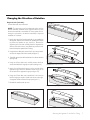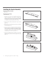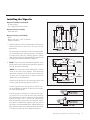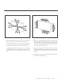
1
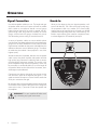
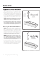
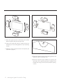
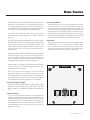
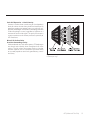
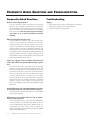
V I G N E T T E™
™
u s e r ’ s
m a n u a l
MA R T I N LOGA N ®
the loudspeaker technology company
CONTENTS
AND INTRODUCTION
Contents
Contents and Introduction . . . . . . . . . . . . . . . . . . .2
Contents
Introduction
Installation in Brief . . . . . . . . . . . . . . . . . . . . . . . .3
Operation . . . . . . . . . . . . . . . . . . . . . . . . . . . . . . .4
Signal Connection
On Wall/Off Wall Switch
Break-In
Mounting the Vignette On A Wall or Ceiling . . . . .5
Which Way Should It Rotate?
Preparing For Vertical Installation . . . . . . . . . . . . . . . 6
Preparing For Horizontal Installation
Changing the Direction of Rotation . . . . . . . . . . . . . . 7
Installing the Bracket Assembly . . . . . . . . . . . . . . . . . 8
Installing the Vignette. . . . . . . . . . . . . . . . . . . . . . . . 9
Home Theater . . . . . . . . . . . . . . . . . . . . . . . . . . .13
ATF (Advanced Thin Film) . . . . . . . . . . . . . . . . . .14
Frequently Asked Questions and Troubleshooting 16
General Information . . . . . . . . . . . . . . . . . . . . . .17
Specifications
Warranty and Registration
Service
Glossary of Audio Terms . . . . . . . . . . . . . . . . . . .18
2
Contents & Introduction
Introduction
Congratulations! You have invested in a new world
of home cinema!
The MartinLogan Vignette represents the culmination of
an intensive, dedicated group research program directed
toward establishing a world class reference monitor utilizing
leading-edge technology, without compromising durability,
reliability, craftsmanship or aesthetic design.
The materials in your new Vignette speaker are of the highest quality and will provide years of enduring enjoyment
and deepening respect. The cabinetry is constructed from
the highest quality HIPP (high-impact polypropylene) to create an acoustically inert, high-density enclosure.
This User’s Manual will explain in detail the operation of
your Vignette speaker and the philosophy applied to their
design. A clear understanding of your speaker will insure
that you obtain maximum performance and pleasure from
this most exacting transducer. It has been designed and constructed to give you years of trouble-free listening enjoyment.
INSTALLATION
We know you are eager to hear your new Vignette loudspeaker, so this section is provided to allow fast and easy
set up. Once you have it operational, please take the time to
read, in depth, the rest of the information in this manual.
It will give you perspective on how to attain the greatest
possible performance from this most exacting transducer.
If you should experience any difficulties in the setup or
operation of your Vignette speaker, please refer to the
Operation or Mounting sections of this manual.
Should you encounter a persistent problem that cannot be
resolved, please contact your authorized MartinLogan dealer.
They will provide you with the appropriate technical analysis to alleviate the situation.
WARNING!
•Refer servicing to a qualified technician.
•To prevent fire or shock hazard, do not
expose this module to moisture.
•Turn amplifier off should any abnormal
conditions occur.
•Do not drive speaker beyond its rated power.
IN
BRIEF
Step 1: Unpacking
Remove your new Vignette speaker from the packing.
Step 2: Placement
Place the Vignette near the desired location. Please see
the ‘Mounting the Vignette On a Wall or Ceiling’ section
(page 5–12) for more placement details.
Step 3: Signal Connection
Use the best speaker cables you can. Higher quality cables,
available from your specialty dealer, are recommended
and will give you superior performance. Spade connectors
are suggested for optimum contact and ease of installation.
Attach your speaker cables to the signal input section on
the rear panel. Be consistent when connecting speaker leads
to the terminals on the back of the Vignette. Take great
care to assign the same color to the (+) terminal on both
the speaker and the amplifier. Please see the ‘Operation’
section (page 4) for more details.
Step 4: Listen and Enjoy
Now, you may turn on your system and enjoy!
The lightning bolt flash with arrowhead symbol within
an equilateral triangle is intended to alert the user to
the presence of uninsulated “dangerous voltage” within
the product’s enclosure that may be of sufficient magnitude to constitute a risk of electric shock.
The exclamation point within an equilateral triangle is
intended to alert the user to the presence of important
operating and maintenance (servicing) instructions in
the literature accompanying the appliance.
Installation in Brief
3
OPERATION
Signal Connection
Use the best speaker cables you can. The length and type
of speaker cable used in your system will have an audible
effect. Under no circumstance should a wire of gauge
higher (thinner) than #16 be used. In general, the longer the length used, the greater the necessity of a lower
gauge, and the lower the gauge, the better the sound,
with diminishing returns setting in around #8 to #12.
Break-In
When you first begin to play your Vignette speaker, it will
sound a bit bass shy. This is due to the high-quality, longlife components used in our woofer. Our custom made
woofers require at least 30 hours of break-in at 90 dB
(moderate listening levels) before any critical listening. The
break-in requirements of the crossover components (and,
to a lesser degree, the ATF transducer) are equal.
A variety of speaker cables are now available whose
manufacturers claim better performance than standard heavy
gauge wire. We have verified this in many cases, and the
improvements available are often more noticeable than the
differences between wires of different gauge. The effects
of cables may be masked if the equipment is not of the
highest quality.
We also recommend, if possible, that short runs of speaker
cable connect the power amplifier and speaker and that
high quality long interconnect cables be used to connect
the preamplifier and power amplifier. This results in the
power amplifiers being close to the speakers, which may
be practically or cosmetically difficult, but if the length of
the speaker cables can be reduced to a few meters, sonic
advantages may be obtained.
Connections are done at the signal input section on the
rear electronics panel of the Vignette (see figure 1). Use
spade connectors for optimum contact. Make certain that
all of your connections are tight.
Be consistent when connecting speaker leads to the terminals
on the back of the Vignette. Take great care to assign the
same color to the (+) terminal on both the speaker and
the amplifier.
WARNING! Turn your amplifier off before making or breaking any signal connections!
4
Operation
Figure 1. Single wire connection. One channel shown.
MOUNTING
THE
VIGNETTE ON A WALL
OR
CEILING
Figure 2. The parts of the Vignette bracket assembly.
NOTE: MartinLogan recommends using 5 wall anchors
to secure each Vignette to a wall. During the installation,
if any of the screw/wall anchor positions are over a stud,
it is recommended to screw directly into the stud.
NOTE: To assure that your Vignette is safely wall mounted, these instructions must be carefully followed. Study
them thoroughly before installing your Vignette's.
Figure 3. Vertical Installation. Rotation direction for various installation locations.
NOTE: The following instructions assume the mounting
surface is of standard wood frame and standard sheet rock
construction. If you wish to mount the Vignette to another
type of material, you should consult a bonded contractor.
WARNING! Installing the Vignette on a wall requires
only 1 person, but an assistant will be helpful.
The bracket assembly shipped with the Vignette
loudspeaker is designed for use only with the
Vignette. Use with other appliances may result in
instability causing possible injury. To prevent injury,
this apparatus must be securely attached to the
wall in accordance with the installation instructions.
Which Way Should It Rotate?
Figure 4. Horizontal Installation. Rotation direction for various installation locations.
The bracket assembly supplied with the Vignette allows the
speaker to mount flat against a wall and pivot up to 90°.
Depending on the installation locations, the Vignette onwall bracket will need to be modified to allow either
counter-clockwise/up or clockwise/down rotation (see
figure 3 and 4). The configuration of Vignette’s bracket
assembly is identical for counter-clockwise and up rotation and is identical for clockwise and down rotation.
Mounting the Vignette On A Wall or Ceiling
5
INSTALLATION
Preparing For Vertical Installation
NOTE: Vignette’s bracket assembly consists of two main
parts: the wall bracket (attaches to the wall) and the cabinet
bracket (attaches to the Vignette). When correctly configured, the wall and cabinet brackets should each have one
pin installed—the wall bracket with an upward pointing
pin in the upper hinge, and the cabinet bracket with a downward pointing pin in the lower hinge (see figures 5 and 6).
Vertical
(CounterClockwise
Rotation)
NOTE: When correctly installed in a vertical orientation, the
Vignette’s cabinet bracket (installed on the cabinet) should
slide down, onto the wall bracket (installed on the wall).
Horizontal
(Up Rotation)
Each Vignette should be installed so that it can rotate to
point towards your listening position (see figure 3). Hold
each Vignette near its desired location and try pivoting it to
assure that each speaker is correctly configured.
Preparing for Horizontal Installation
NOTE: Vignette’s bracket assembly consists of two main
parts: the wall bracket (attaches to the wall) and the cabinet
bracket (attaches to the Vignette). When correctly configured each bracket should have one pin installed—the wall
bracket with a pin installed in the left hinge, pointing to
the left and the cabinet bracket with a pin installed in the
right hinge, pointing to the right (see figures 5 and 6).
NOTE: When the Vignette is correctly installed in a horizontal orientation, gravity will pull on the speaker trying to
rotate it down. The Vignette bracket assembly is designed in
such a way that the force of gravity will tighten the left cap
nut and prevent the speaker from rotating.
Figure 5. Vignette’s bracket assembly configured for counter-clockwise/
up rotation
Vertical
(Clockwise
Rotation)
Horizontal
(Down Rotation)
Each Vignette should be installed so that it can rotate to
point towards your listening position (see figure 4). Hold
each Vignette near its desired location and try pivoting it
to assure that each speaker is correctly configured.
Figure 6. Vignette’s bracket assembly configured for clockwise/down
rotation.
6
Mounting the Vignette On A Wall or Ceiling
Changing the Direction of Rotation
Required tools (included):
2.5mm Allen tool, 6mm Allen tool
NOTE: This procedure can be performed either with the
bracket assembly installed on the Vignette cabinet or with
the bracket assembly uninstalled. For the purpose of illustrating this procedure, the bracket assembly is depicted
installed on a cabinet.
1 Ignore this step if the bracket assembly is not installed on
the Vignette. Prepare a flat surface with padding and sheets
to protect the speaker as you work on it. Remove the
Vignette's grill cover and carefully place the Vignette face
down on the work surface, using books or pieces of cardboard to keep the speaker from rocking.
Figure 8. Remove the wall bracket from the cabinet bracket.
2 Using the 6mm Allen tool, remove the 2 cap nuts and washers from the hinges. Place them aside (see figure 7).
3 Carefully remove the wall bracket from the cabinet bracket
(see figure 8).
4 Using the 2.5mm Allen tool, carefully remove the 2 set
screws that hold the 2 hinge pins in place (see figure 9).
Figure 9. Remove the 2 set screws.
5 Move the wall bracket hinge pin to the outside of the
opposite hinge. Move the cabinet bracket hinge pin to
the outside of the opposite hinge (see figure 10).
6 Using the 2.5mm Allen tool, reinstall the 2 set screws to
lock the hinge pins in place. Make sure the set screw tightens against the flat surface of the pin (see figure 11).
7 Reinstall the washers and cap nuts.
Figure 10. Change hinge pin locations.
Figure 7. Remove the 2 cap nuts and washers from the hinges.
Figure 11. Reinstall the two set screws to hold hinge pins in place.
Mounting the Vignette On A Wall or Ceiling
7
Installing the Bracket Assembly
Required hardware (included):
(6) M4 screws
Required tools (included):
2.5mm Allen tool
1 Prepare a flat surface with padding and sheets to
protect the speaker as you work on it. Remove the
Vignette's grill cloth and carefully place the Vignette
face down on the work surface, using books or pieces
of cardboard to keep the speaker from rocking.
Figure 12. Loosen the 2 cap nuts.
2 Using the 6mm Allen tool, loosen the 2 cap nuts (see
figure 12).
3 Rotate/open the wall bracket away from the cabinet
bracket (see figure 13).
4 Align the 6 holes in the Vignette's wall mounting bracket with the holes on the back of the Vignette's cabinet.
Please note that the wall bracket should lie flat against
the Vignette cabinet with the hinges along the flat,
straight edge of the cabinet (see figure 14).
Figure 13. Rotate/open the wall bracket away from the cabinet bracket.
5 Using the 2.5MM Allen tool, install the 6 screws that
attach the cabinet bracket and firmly tighten them (see
figure 15).
Figure 14. Align the 6 holes on the mounting bracket with those of the Vignette.
Figure 15. Install 6 screws.
8
Mounting the Vignette On A Wall or Ceiling
Installing the Vignette
Required hardware (included):
(5) wall anchors
(5) 1" Phillips head wood screws
Required tools (included):
6mm Allen tool
Required tools (not included):
Level
Electric drill and 1/4" and 1/8" drill bits
Phillips screwdriver
1 Hold the Vignette at the desired location. Examine the
mounting location to assure that the wall is free of
obstructions.
Test the direction of rotation to assure that the speaker
can rotate toward your listening position. If the speaker rotates away from your listening position, please
refer to 'Which Direction Should It Rotate?' (page 5) and
‘Changing the Direction of Rotation’ (page 7).
2 NOTE: These instructions describe the position of the
wall bracket with the Vignette mounted flush against a
wall (not rotated on its bracket).
NOTE: The center point of the wall-bracket is not the
same as the center of the Vignette. These directions
describe the location of the center of the wall-bracket, which you will need to know in order to mount the
speaker at your desired location.
CounterClockwise
Rotation
Clockwise
Rotation
Figure 16. Determining the wall brackets center point in a vertical installation.
Down
Rotation
Up
Rotation
Determine the location for the center point of the wall
bracket. Mark this spot (see figures 16 and 17).
Will the Vignette remain flat against the wall? If so, it
can be installed flush against an object such as a plasma screen (see figure18).
Will the Vignette be rotated to point towards the listening position? If so you need to leave space between
the nearest object to allow clearance for the speaker
to pivot (see figure 18). 5” (12.7cm) of clearance will
allow the Vignette to pivot within its full range of motion.
Less space is needed if the Vignette does not need to
fully rotate. As recommended above, before drilling any
holes, hold the Vignette at its desired location and rotate
it into place to assure you have adequate clearance.
Figure 17. Determining the wall brackets center point in a horizontal installation.
Figure 18. Clearance requirements to allow rotation of the Vignette.
Mounting the Vignette On A Wall or Ceiling
9
Figure 19. Mark the center points.
Figure 20. Use a level to square the wall bracket and mark the other 4 holes.
NOTE: Figures 19–24 illustrate the Vignette mounted in 4
different configurations.
4 Using a level, square the wall bracket and hold it flush
against the wall with the wall bracket's center hole over
the point you just marked. The cylindrical hinges on the
wall bracket should point away from the wall and the
flat plane of the wall bracket should be flush against
the wall. Mark 4 points inside of the wall bracket's arc
shaped cut outs located at either end of the wall bracket
(see figure 20).
3 Mark your wall with the center point for the wall bracket
(see figure 19).
10
Mounting the Vignette On A Wall or Ceiling
Figure 21. Drill pilot holes and/or sink wall anchors at the 5 marked locations.
Figure 22. Using a level, square the wall bracket and install the screws.
5 Set the wall bracket aside. Using a 1/8" bit, drill a pilot
hole at all five points marked in the previous steps.
If a pilot hole hits a stud during this step, DO NOT WIDEN
that pilot hole or install a wall anchor at that location.
6 Mount the wall bracket to the center wall anchor (or
pilot hole) using a 1" Phillips head screw driven through
the wall brackets center point. Do not fully tighten the
screw—the bracket must be leveled before installing the
remaining screws (see figure 22).
If a pilot hole does not hit a stud, use a 1/4" bit to widen
that pilot hole and using a Phillips screwdriver install a
wall anchor so that it is flush with the wall (see figure
21).
7 Using a level, square the bracket and drive the four
remaining 1" Phillips head screws into the wall anchors
(or pilot holes). Do not fully tighten the screws (see figure 22).
8 Using a level, make sure the bracket is level and tighten
all five screws (see figure 22).
Mounting the Vignette On A Wall or Ceiling
11
Figure 23. Install the Vignette and the washers and cap nuts.
Figure 24. Rotate the Vignette into position and tighten the cap nuts.
9 Place the Vignette onto the wall bracket and carefully
slide the Vignette into place (see figure 23).
10 Using a 6mm Allen tool, attach a washer and cap nut
onto each pin. Do not fully tighten the cap nuts (see figure 23).
11 Make the signal connections from the amplifier (see
‘Operation’, pages 4).
Figure 25. Rotate the Vignette’s logo medallion so it is correctly orientated.
12 Rotate the Vignette to point at the listening position and
tighten the cap nuts (see figure 24).
13 Rotate the Vignette’s logo medallion, by removing the
grill cloth cover, gently pressing the medallion from
behind and turning it to the correct orientation (see figure 25).
12
Mounting the Vignette On A Wall or Ceiling
HOME THEATER
It had long been the practice of stereo buffs to connect their
television to a stereo system. The advantage was the use
of the larger speakers and more powerful amplifier of the
stereo system. Even though the sound was greatly improved,
it was still mono and limited by the broadcast signal.
In the late 1970’s and early 1980’s two new home movie
formats became widely available to the public: VCR and
laser disc.
Surround Speakers
We recommend that the surround speakers play down
to 80 Hz or below. The surround speakers contain the
information that makes it appear that planes are flying over
your head. Some may suggest that this is the place to save
money and purchase a small, inexpensive speaker. If you
choose to do so, be prepared to upgrade in the future as
discrete six-channel digital encoding becomes available
and the demands on the surround speakers increase.
By 1985, both formats had developed into very high quality
audio/video sources. In fact, the sonic performance of some
video formats exceeded audio-only formats. Now, with
theater-quality sound available at home, the only element
missing was the "surround sound" presentation found in
movie houses.
Subwoofer
With any good surround system you will need a high-quality
subwoofer (the .1 in a 5.1 channel surround system). Most
movie soundtracks contain large amounts of bass information as part of the special effects. Good subwoofers
will provide a foundation for the rest of the system.
Fortunately, Dolby and DTS-encoded movies (which include
almost all movies) have the same surround sound information encoded on home releases as the theater films. All
that is required to retrieve this information is a decoder
and additional speakers and amps to reproduce it.
Home theater is a complex purchase and we recommend
that you consult your local MartinLogan dealer, as they
are well versed in this subject.
Each piece of a surround system can be purchased
separately. Take your time and buy quality. No one has
ever complained that the movie was too real. The following
list and descriptions will give you only a brief outline of the
responsibilities and demands placed on each speaker.
Front Left and Front Right
If these speakers will be the same two used for your stereo
playback, they should be of very high quality and able
to play loudly (over 102 dB) and reproduce bass below 80
Hz.
Center Channel
This is the most important speaker in a video system, as
almost all of the dialogue and a large portion of the front
speaker information is reproduced by the center channel.
It is important that the center speaker be designed by
the same manufacturer as the front speakers, and that it is
recommended for use as a center speaker. This is not the
place to cut corners.
Figure 26. Vignette loudspeakers as front, center and surround (effects)
channels. Grotto subwoofers as 0.1 (effects) channel.
Home Theater
13
ATF (ADVANCED THIN FILM)
ATF Operation
The MartinLogan ATF transducer (based on RADIA planar
technology) consists of a micro-thin, low-mass Kaladex
diaphragm with an ultra-light, etched conductive aluminum surface suspended between two high field strength
neodymium super magnet arrays (see figure 27). When an
electrical current (music signal) passes through the etched
aluminum on the diaphragm's surface it is simultaneously
pulled towards one of the neodymium arrays and pushed
away from the opposing array. When the direction of current
is reversed the diaphragm is simultaneously pushed and
pulled in the opposite direction, thus producing sound.
Extremely Low-Mass Diaphragm
—Blazing Speed and Inner Detail
Low-mass diaphragms are crucial to a loudspeaker's ability
to accurately reproduce sound. As the mass of a transducer's
diaphragm decreases, its ability to resolve detail increases.
With extremely low-mass characteristics, the ATF transducer
tracks the audio signal with almost perfect accuracy.
14
ATF (Advanced Thin Film)
MartinLogan ATF diaphragms are constructed of extremely
low mass Dupont Kaladex® PEN (polyethylene naphthalate) —a material chemically similar to the low-mass PET
(polyethylene terathylate) film used in MartinLogan's generation 2 electrostatic transducers, yet capable of handling
the high thermal requirements required for stable magnetic
thin film operation.
High Field Strength
—Superb Control and Efficiency
With a field strength almost 2000% more powerful than
traditional systems, Neodymium iron boron (NIB) rare-earth
super magnets are one of the world's strongest commercially available magnetic materials. This incredible field
strength proves ideal for maintaining perfect control over
the low-mass Kaladex diaphragm. Super-low distortion
levels, high-resolution, and crystal-clear transparency are
just a few of the benefits resulting from this superb combination of low-mass diaphragm and high field strength.
Push-Pull Operation = Ideal Linearity
Linearity is another factor contributing to a loudspeaker's
ability to achieve ultimate clarity, detail and resolution. By
positioning neodymium magnet arrays in a push-pull configuration, MartinLogan ATF transducer technology maintains
uniform diaphragm control, regardless of position as it
traverses the entire audio signal. The push-pull concept is
a major contributor to the linearity and sonic superiority of
ATF transducers.
Direct Full-Surface Drive
Provides Outstanding Clarity
Unlike traditional voice coil driven systems, ATF diaphragms
are directly and uniformly driven throughout their entire
surface. This full-surface drive system results in ultra-fast
transient response with no cone break up and the ability
to accurately reproduce sound with great delicacy, nuance
and clarity.
Figure 27. Cut away view of an ATF transducer. Note the simplicity due
to minimal part usage.
ATF (Advanced Thin Film)
15
FREQUENTLY ASKED QUESTIONS
AND
TROUBLESHOOTING
Frequently Asked Questions
Troubleshooting
How do I clean my speakers?
Just use a dust free cloth or a soft brush to remove the
dust from your speakers. We recommend a specialty
cloth (available at the Xtatic shop at www.martinlogan.
com) that cleans your speakers better than anything
else we have tried. Do not spray any kind of cleaning agent on or in close proximity to the ATF
element.
Output
• Check that all your system components are turned on.
• Check your speaker wires and connections.
• Check all interconnecting cables.
What size amplifier should I use?
We recommend an amplifier with 100 watts per channel for most applications. Probably less would be
adequate when used in home theater where a subwoofer is employed. Our hybrid designs will perform
well with either a tube or transistorized amplifier, and
will reveal the sonic character of either type. However,
it is important that the amplifier be stable operating into
varying impedance loads: a stable amplifier will be
able to deliver twice its rated wattage into 4 Ohms and
should again double into 2 Ohms.
Could you suggest a list of suitable electronics and
cables that would be ideal for MartinLogan speakers?
The area of electronics and cable choice is probably
the most common type of question that we receive. It is
also the most subjective. We have repeatedly found that
brands that work well in one setup will drive someone
else nuts in another. We use many brands with great
success. Again, we have no favorites; we use electronics and cables quite interchangeably. We would
suggest listening to a number of brands—and above
all else—trust your ears. Dealers are always the best
source for information when purchasing additional audio
equipment.
Is there likely to be any interaction between my speakers and the television in my Audio/Video system?
The MartinLogan Vignette loudspeaker is fully shielded
and can go anywhere.
Will exposure to sunlight affect the life or performance of my speakers?
We recommend that you not place any loudspeaker
in direct sunlight. The ultraviolet (UV) rays from the sun
can cause deterioration of grill cloth, speaker cones, etc.
Small exposures to UV will not cause a problem. In
general, the filtering of UV rays through glass will greatly
reduce the negative effects.
16
Frequently Asked Questions and Troubleshooting
GENERAL INFORMATION
Specifications
Warranty and Registration
System Frequency Response
78–20,000 Hz ± 3 dB
Your Vignette speaker is provided with an automatic Limited
90 Day Warranty coverage.
Sensitivity
89 dB/2.83 volts/meter (mounted on wall)
You have the option, at no additional charge, to receive a
Limited 5 Year Warranty coverage. To obtain the Limited
5 Year Warranty coverage you need to complete and return
the Certificate of Registration, included with your speakers,
and provide a copy of your dealer receipt to MartinLogan
within 30 days of purchase.
Impedance
6 ohms
Crossover Frequency
2200 Hz
For your convenience MartinLogan also offers online warranty
registration at www.martinlogan.com.
Components
Air core coils, metal film and low dissipation electrolytic
capacitors
MartinLogan may not honor warranty service claims unless
we have a completed Warranty Registration on file!
Woofer Type
Two 4” (10.2cm) magnetically shielded high rigidity
aluminum cones with extended throw drive assembly, nonresonance asymmetrical chamber format; bass reflex
If you did not receive a Certificate of Registration with your
new Vignette speaker, you cannot be assured of having
received new units. If this is the case, please contact your
authorized MartinLogan dealer.
ATF High Frequency Driver
1.5" x 2.25" (3.8cm x 5.7cm) ATF Transducer
Power Handling
125 watts
Weight
14 lbs. each (6.4 kg)
Size Without Wall Bracket
19.5” inches W × 4.5” inches D × 7.1875” inches H
(49.5cm W × 12.54cm D × 18.3cm H)
Size With Wall Bracket (Flat)
19.5” inches W × 5.26” inches D × 7.1875” inches H
(49.5cm W × 14.45cm D × 18.3cm H)
Service
Should you be using your MartinLogan product in a country
other than the one in which it was originally purchased,
we ask that you note the following:
1 The appointed MartinLogan distributor for any given
country is responsible for warranty servicing only on
units distributed by or through it in that country in
accordance with its applicable warranty.
2 Should a MartinLogan product require servicing in a
country other than the one in which it was originally
purchased, the end user may seek to have repairs performed by the nearest MartinLogan distributor, subject
to that distributor’s local servicing policies, but all cost
of repairs (parts, labor, transportation) must be born by
the owner of the MartinLogan product.
3 If, after owning your speakers for six months, you
relocate to a country other than the one in which
you purchased your speakers, your warranty may be
transferable. Contact MartinLogan for details.
General Information
17
GLOSSARY
OF
AUDIO TERMS
AC. Abbreviation for alternating current.
DC. Abbreviation for direct current.
Active crossover. Uses active devices (transistors, ICs, tubes)
and some form of power supply to operate.
Diffraction. The breaking up of a sound wave caused by
some type of mechanical interference such as a cabinet edge,
grill frame or other similar object.
Amplitude. The extreme range of a signal. Usually measured from the average to the extreme.
Arc. The visible sparks generated by an electrical discharge.
ATF. The abbreviation for advanced thin film.
Bass. The lowest frequencies of sound.
Bi-Amplification. Uses an electronic crossover, or line-level
passive crossover, and separate power amplifiers for the
high and low frequency loudspeaker drivers.
Capacitance. That property of a capacitor which determines how much charge can be stored in it for a given
potential difference between its terminals, measured in
farads, by the ratio of the charge stored to the potential
difference.
Capacitor. A device consisting of two or more conducting
plates separated from one another by an insulating material
and used for storing an electrical charge. Sometimes called
a condenser.
Clipping. Distortion of a signal by its being chopped off. An
overload problem caused by pushing an amplifier beyond
its capabilities. The flat-topped signal has high levels of
harmonic distortion which creates heat in a loudspeaker
and is the major cause of loudspeaker component failure.
CLS. The abbreviation for curvilinear linesource.
Crossover. An electrical circuit that divides a full bandwidth
signal into the desired frequency bands for the loudspeaker
components.
dB (decibel). A numerical expression of the relative loudness
of a sound. The difference in decibels between two sounds
is ten times the Base 10 logarithm of the ratio of their power
levels.
18
Glossary of Audio Terms
Diaphragm. A thin flexible membrane or cone that vibrates
in response to electrical signals to produce sound waves.
Distortion. Usually referred to in terms of total harmonic
distortion (THD) which is the percentage of unwanted harmonics of the drive signal present with the wanted signal.
Generally used to mean any unwanted change introduced
by the device under question.
Driver. See transducer.
Dynamic Range. The range between the quietest and the
loudest sounds a device can handle (often quoted in dB).
Efficiency. The acoustic power delivered for a given electrical
input. Often expressed as decibels/watt/meter (dB/w/m).
ESL. The abbreviation for electrostatic loudspeaker.
Headroom. The difference, in decibels, between the peak
and RMS levels in program material.
Hybrid. A product created by the marriage of two different
technologies. Meant here as the combination of a dynamic woofer with an electrostatic or ATF transducer.
Hz (Hertz). Unit of frequency equivalent to the number of
cycles per second.
Imaging. To make a representation or imitation of the original sonic event.
Impedance. The total opposition offered by an electric
circuit to the flow of an alternating current of a single frequency. It is a combination of resistance and reactance and
is measured in ohms. Remember that a speaker’s impedance changes with frequency, it is not a constant value.
Inductance. The property of an electrical circuit by which
a varying current in it produces a varying magnetic field
that introduces voltages in the same circuit or in a nearby
circuit. It is measured in henrys.
Inductor. A device designed primarily to introduce inductance into an electrical circuit. Sometimes called a choke
or coil.
Linearity. The extent to which any signal handling process
is accomplished without amplitude distortion.
Midrange. The middle frequencies where the ear is the
most sensitive.
NAC. The abbreviation for natural ambience compensation.
Passive crossover. Uses no active components (transistors, ICs, tubes) and needs no power supply (AC, DC,
battery) to operate. The crossover in a typical loudspeaker is of the passive variety. Passive crossovers consist of
capacitors, inductors and resistors.
Phase. The amount by which one sine wave leads or lags
a second wave of the same frequency. The difference is
described by the term phase angle. Sine waves in phase
reinforce each other; those out of phase cancel.
Pink noise. A random noise used in measurements, as it
has the same amount of energy in each octave.
Polarity. The condition of being positive or negative with
respect to some reference point or object.
RMS. Abbreviation for root mean square. The effective value
of a given waveform is its RMS value. Acoustic power is
proportional to the square of the RMS sound pressure.
Resistance. That property of a conductor by which it opposes the flow of electric current, resulting in the generation
of heat in the conducting material, usually expressed in
ohms.
Resistor. A device used in a circuit to provide resistance.
Resonance. The effect produced when the natural vibration frequency of a body is greatly amplified by reinforcing
vibrations at the same or nearly the same frequency from
another body.
Sensitivity. The volume of sound delivered for a given
electrical input.
Stator. The fixed part forming the reference for the moving
diaphragm in a planar speaker.
THD. The abbreviation for total harmonic distortion. (See
Distortion)
TIM. The abbreviation for transient intermodulation distortion.
Transducer. Any of various devices that transmit energy
from one system to another, sometimes one that converts
the energy in form. Loudspeaker transducers convert electrical energy into mechanical motion.
Transient. Applies to that which lasts or stays but a short
time. A change from one steady-state condition to another.
Tweeter. A small drive unit designed to reproduce only
high frequencies.
Wavelength. The distance measured in the direction of
progression of a wave, from any given point characterized
by the same phase.
White noise. A random noise used in measurements, as it
has the same amount of energy at each frequency.
Woofer. A drive unit operating in the bass frequencies only.
Drive units in two-way systems are not true woofers but
are more accurately described as being mid/bass drivers.
Glossary of Audio Terms
19
MA R T I N LOGA N ®
the loudspeaker technology company
2101 Delaware Street, Lawrence, Kansas 66046, USA
tel 785.749.0133
fax 785.749.5320
©2003 MartinLogan. All rights reserved.
www.martinlogan.com
Rev. #080604