1
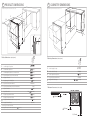
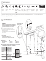
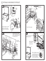
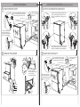
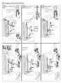
Installation instructions
DishDrawer®
US CA
DD24DT models
Important!
SAVE THESE INSTRUCTIONS
The models shown in this document may not be available in all markets and are subject to change at any time. For current details about model and specification availability in your country, please go to our
website www.dcsappliances.com or contact your local DCS Customer Care Representative.
1 SAFETY AND WARNINGS
WARNING!
Electrical hazard
Before installing the DishDrawer®, remove the house fuse or open the circuit
breaker.
If permanently connecting the DishDrawer®, be sure the power is isolated and
the DishDrawer® unplugged.
GROUNDING INSTRUCTIONS
This appliance must be grounded. In the event of a malfunction or breakdown,
grounding will reduce the risk of electric shock by providing a path of least
resistance for electric current. This appliance is equipped with a cord having
an equipment-grounding conductor and a grounding plug. The plug must be
plugged into an appropriate outlet that is installed and grounded in accordance
with all local codes and ordinances. WARNING - Improper connection of the
equipment-grounding conductor can result in a risk of electric shock. Check with
a
electrician or service representative if you are in doubt as to whether
the appliance is properly grounded.
If the DishDrawer is installed as a permanently connected appliance:
GROUNDING INSTRUCTIONS - This appliance must be connected to a grounded
metal, permanent wiring system, or an equipment-groounding conductor must
be run with the circuit conductors and connected to the equipment-grounding
terminal or lead on the appliance.
Do not modify the power supply plug provided with the appliance - if it will not
the outlet, have a proper outlet installed by a
ed electrician. Do not use
an extension cord, adapter plug or multiple outlet box.
Failure to follow this advice may result in electrical shock or death.
WARNING!
Cut hazard
Take care - panel edges are sharp.
Failure to use caution could result in injury or cuts.
Important safety instructions!
Installation of this DishDrawer® requires basic mechanical and electrical skills.
Be sure to leave these Instructions with the Customer.
Installation must comply with your local building and electricity regulations.
At the completion of the DishDrawer® installation, the Installer must perform
Final Check List.
Remove all packaging materials supplied with the DishDrawer®.
This DishDrawer® is manufactured for indoor use only.
Ensure all water connections are turned OFF. It is the responsibility of the plumber and
electrician to ensure that each installation complies with all Codes and Regulations.
The DishDrawer® MUST be installed to allow for future removal from the enclosure if service is required.
The switched power outlet must be outside the DishDrawer® cavity so that it is accessible after
installation.
Care should be taken when the appliance is installed or removed to reduce the likelihood of damage to
the power supply cord.
If the DishDrawer® is to be relocated from one installation to another it must be kept upright to avoid
damage from water spillage.
Make sure only new hoses are used for connection (supplied with DishDrawer®). Old hoses should not
be reused.
Failure to install the DishDrawer® correctly could invalidate any warranty or liability claims.
If the product is installed in a motor vehicle, boat or similar mobile facility, you must bring the vehicle,
boat or mobile facility containing the product to the service shop at your expense or pay the service
technician’s travel to the location of the product.
2 PRODUCT DIMENSIONS
3 CABINETRY DIMENSIONS
C
B
M
D
I
B
Installation diagrams for illustration purposes only
Installation diagrams for illustration purposes only
D
G
K
H
C
E
E
C
L
A
G
N
M
F
I
J
overall height* of product
B
C
D
E
F
G
H
I
J
K
L
M
N
overall width of product
(605)
overall depth of product (excl. curvature/handle)
(577)
depth of drawer (open) (excl. curvature/handle)
(545)
(863.5- 923.5)
height* of chassis
(853)
height range of levelling feet
(60)
depth of chassis (incl. trimseal)
DD24DT
A
Cabinetry dimensions (inches (mm))
nished
Flat door
DD24DT
nished
Flat door
Product dimensions (inches (mm))
A
inside height of cavity
B
C
D
E
inside width of cavity
34 - 36 ½”
(864 - 926.5)
24 ” (610)
inside depth of cavity (inside)
22
height of adjacent cabinetry
height of toekick space
3
-6
21 ¾” (552)
depth of drawer front panel (excl. curvature/handle)
1 ” (25)
depth of handle
(81)
depth of toekick
2¼
(442)
height of lower drawer front
(312)
height of installation bracket slots (on top of chassis)
height of drawer fronts
Minimum clearances (inches (mm))
(57 - 117)
height of upper drawer front
” (2.5 mm)
(2)
30 ” (762)
* Chassis heights include bracket slots
Note: height from top of handle to top of drawer -
(62 mm).
” (580)
30” (762)
” (2.5 mm)
½” (13 mm)
” (100 - 160)
A
4 PARTS SUPPLIED
Drain hose
support (1)
Drain hose
joiner (1)
Wire clip (2)
Clamp (1)
Side mounting
bracket kit
(A and B) (2)
OPTIONAL
Top
mounting
brackets (2)
Phillips
Rubber
16 mm
washer for
screws (9) inlet hose
(1)
Moisture protection
tape (1)
(to prevent moisture
damage)
Edge protector (1)
(if services hole
partition is metal)
Hexagonal
socket (2)
(long & short)
Prefinished toekick (1)
white or black
If the Drain hose(s) supplied are not long enough to reach your services, you must use a Drain Hose Extension Kit P/N 525798 which will extend the drain hose(s) by 11’ 10” (3.6 m). The kit is available from the nearest
DCS Authorized Service Agent, or Toll free 1.888.936.7872 or www.dcsappliances.com.
5 CAVITY PREPARATION
Important!
*
Be sure the edges of the services hole are smooth or covered. If the services
hole is through a metal partition the hole must be protected with the Edge
protector supplied to prevent damage to the power cord or hoses.
These marks indicate mounting bracket screw locations
Preferred position. If adequate clearance, services hole can be
higher to clear toekick space.
If hole is higher, ensure drain hose(s) are routed straight into the
waste connection.
If no side partition, use a
brace for securing.
Moisture
protection
(10 mm) tape must
be applied.
c a te d
n be loer®.
a
c
s
e
ic
r aw
er v
Note: Sside of DishD
r
e
h
eit
2” x 4”
Water Connection
Recommended HOT (Maximum 140°F/60°C).
Supplied hose to suit 3/8” (9 mm) male compression fitting.
Water Pressure
Water softener models
Other models
Max
1 MPa (145 psi)
1 MPa (145 psi)
Min
0.1 MPa (14.5 psi)
0.03 MPa (4.3 psi)
Drains will need to be separated to satisfy kosher requirements. We suggest you confirm
acceptability with your local rabbi in respect to kosher installations.
Max. distance of
hoses and cord from
chassis edge
Drain hose
Inlet hose
Power cord (excl. plug)
Left hand
side
Right hand
side
78 ½”
70 ½”
(2000 mm)
(1800 mm)
64 ¾”
49”
(1650 mm)
(1250 mm)
29 ½”
27 ½”
(750 mm)
(700 mm)
max. 17
(450 mm)
max. ø 1 ½”
”
Water supply
(38 mm)
min.7 ”
Left hand
side
Right hand
side
*
*
(200 mm)
110-120 VAC
max. 15 A
6 OPTIONALLY HARD WIRING THE PRODUCT
B
A
5 ”
mm)
(150
30 mm
2
Remove the
access cover
4
5
1
6
3
8
7
Ensure the drawer is removed
and then rotated counterclockwise to prevent kinked
hoses.
Remove Power supply
Access cover
8
C
Remove knock-out for cable
clamp. Fit suitable cable clamp
for the conduit and terminate
the wiring as shown.
7
D
Ensure the drawer clips on 16
both sides are reset.
15
Use copper
conductors only.
Ensure the drawer
15
is now rotated
clockwise back.
11
11
10
12
13
9
14
17
Before refitting the drawer,
ensure the hoses are not
twisted and the latches at
the rear of each drawer
runner are facing forward.
7 ROUTE THE HOSES
2
OR
Tie together to
avoid kinking.
1
SECURE WITHOUT DRAWER REMOVAL (FRAMELESS CABINETRY ONLY)
SECURE BY DRAWER REMOVAL
8 MOVE INTO THE CAVITY
2
8 ATTACH SIDE MOUNTING BRACKETS
Ensure hoses and
cord are not kinked
or twisted.
If top mounting brackets are being
used, ensure they’re securely fitted
before sliding product into cavity.
Clip all four side mounting brackets into their
slots using a flat-bladed screwdriver. Ensure
they’re securely fitted before sliding product
into cavity.
optional
(x2)
optional
3
3
Loosen feet only and take
care when pushing the
product into the cavity that
you do not bend the feet.
1
1
The mounting slots are in pairs, one on each side
diagonally across the product. A bracket must
match A slot and B bracket must match B slot.
9 REMOVE THE DRAWER
9 MOVE INTO THE CAVITY
4
1
2
If top mounting brackets are being
used, ensure they’re securely fitted
before sliding product into cavity.
Ensure hoses and cord
are not kinked or
twisted.
optional
(x2)
Ensure the drawer is
removed and then rotated
counter-clockwise
to prevent kinked hoses.
2
55 ””
mm)
(150
(150 mm)
30
mm
3
5
5
When feet are extended,
take care when pushing
the product into the cavity
that you do not bend the
feet.
3
3
1
1
10 LEVEL AND SECURE THE PRODUCT
Ensure product is level and
aligning with cabinetry.
Using the most appropriate
length Hexagonal socket
supplied, fully extend
levelling feet up to required
distance by hand.
10 SECURE THE PRODUCT
max. ¾” (19 mm)
Open the upper drawer halfway.
Using a flat-bladed screwdriver, prize
the plastic gray plug out of the trim
moulding.
2
C
C
optional
Using a small Philips screwdriver,
screw through the trim moulding,
securing the side mounting
bracket to the cabinetry. Do not
damage the rubber trimseal.
1
2
The product has three pairs of
mounting brackets: a pair of optional
brackets on the top (C) and two pairs
of formed brackets in the side of the
chassis (A,B). Use at least two out of
the three pairs to secure the product.
Ensure the sound insulation is
repositioned
correctly.
Hexagonal socket
1
B
B
A
A
3
OPTIONAL
4¾” (19
optional
mm)
max.
Replace the plastic gray plug back
into the trim moulding and ensure
the trimseal is facing forward.
1
x4
4
3
11 REFIT THE DRAWER
5
FINALLY, FOR BOTH METHODS, FIT THE TOEKICK
Ensure the drawer clips on
both sides are reset.
3
3
Where the toekick
meets the bottom
of the tub is the
cut-off point
1
4
Repeat for all four brackets.
Before refitting the drawer, ensure the
hoses are not twisted and the latches
at the rear of each drawer runner are
facing forward.
5
4
19
19
2
7
6
4
Ensure the drawer
is now rotated
clockwise back.
1
8
2
Important!
Do not overtighten screw.
9
12 PLUMBING AND DRAINAGE OPTIONS
B
DishDrawer® with Waste Disposal 2
If space is limited for fixing, push
hose through drain hose support
to required height
DishDrawer® using Air Break
with Drain Hose Joiner
29 ½”- 34 ¾”
(750 882.5 mm)
C
1
Supplied drain hose joiner
(ø ¾” (19 mm)) waste tee)
max. 4 ¾”
(120 mm)
1
29 ½” - 34 ¾”
29 ½” - 34 ¾”
(7 5 0 - 8 8 2 . 5 m m )
Supplied drain hose joiner
(ø ¾” (19 mm)) waste tee)
29 ½”- 34 ¾”
(750 882.5 mm)
1 ½”
(38 mm)
HIGHLOOP
min. 6”
(150 mm)
37 ” (950 mm)
Max. height to
top of Air Break
(countertop or
wall mounted)
min. R 8 ”
(200 mm)
2
If space is limited for fixing, push
hose through drain hose support
to required height
Air Break
1
DishDrawer® and Standpipe
Ø 1 1/2” (38 mm)
(7 5 0 - 8 8 2 . 5 m m )
A
Waste Disposal
(optional)
min. R 8 ”
(200 mm)
3
Fit supplied
washer
Fit supplied
washer
Ensure hoses are routed
straight to joiner. Remove
excess hose material if
necessary.
4
Ensure hoses are routed
straight to joiner. Remove
excess hose material if
necessary.
4
4
180o
180o
180o
5
5
5
6
6
7
Fit supplied
washer
5
6
5
13 FINAL CHECKLIST
Check all parts are installed.
Ensure product is level, securely fastened to the cabinetry and opens and closes
freely. The DishDrawer® must be free to fully close with no resistance from the
cabinetry.
Ensure inlet hose to water supply has rubber washer fitted and is tightened a
further half turn after seal contact.
Ensure any knockouts or plugs in drain connection have been drilled out and
drain connection has been made.
The drain hose joiner must not support the weight of excess hoses. Keep hoses
as fully extended as possible to prevent sagging. Any excess length of hose
should be kept on the dishwasher side of the high loop.
If using Plumbing and Drainage OPTION A, ensure the Highloop is a minimum
6” (150 mm) higher than the drain hose joiner.
Turn on the power and water supply. Then press the Power ( ) button to turn
the DishDrawer® on. The DishDrawer® should beep and Wash Programme lights
light up.
Check the spray arm is in place and free to rotate.
Spray arm
Add three cups of water into the DishDrawer®. On the Wash Programme
Selector Panel press Rinse and close the drawer(s). Start the programme by
pressing the Start/Pause ( ) button.
After the Rinse programme has finished, ensure machine has run and drained
correctly.
Check water supply and drainage connection for leakage.
14 TROUBLESHOOTING
Excessive water remaining above the filter plate, after the rinse cycle
Check for kinked drain hoses or blocked waste connection, high loop not
properly installed or drain hoses not routed correctly.
No water supply
Check water is connected, turned on and the spray arm(s) are correctly fitted
and free to rotate.
No lights come on when the drawer is opened
Ensure power is connected and is switched on. Check if Auto Power option is
on.
Water around water supply and drainage connections
Check connections, existing plumbing and hoses for leaks. Check washer and
hose clamps are correctly fitted.
If product is tipping
Ensure the product is secured to the cabinetry.
If front panels are misaligned
Check and relevel product. Check the cabinetry is square.
Drawer(s) don’t close properly
Ensure nothing is obstructing the drawer(s) from closing properly eg sound
insulation, hoses or drawer latches.
If a problem occurs, consult the Troubleshooting section of the User Guide.
If after checking these points you still need assistance, please refer to the
User guide for warranty details and your nearest Authorized Service Centre,
or contact us through our website, www.dcsappliances.com.
Repeat for each drawer.
www.dcsappliances.com
599745B US CA 04.09