1
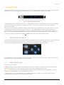
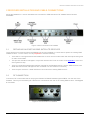
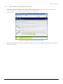
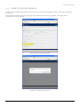
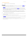
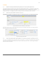
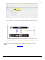
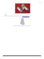
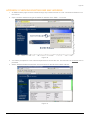
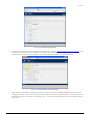
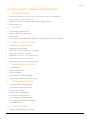
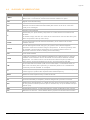
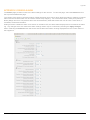
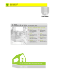
RLS & WNE CLIENT V.5.1 RX8200 CONFIGURATION GUIDE Date of issue: 8th April 2013 WNE v.5.1 Legal Information © Thomson Reuters 2013. All Rights Reserved. Thomson Reuters, by publishing this document, does not guarantee that any information contained herein is and will remain accurate or that use of the information will ensure correct and faultless operation of the relevant service or equipment. Thomson Reuters, its agents and employees, shall not be held liable to or through any user for any loss or damage whatsoever resulting from reliance on the information contained herein. This document contains information proprietary to Thomson Reuters and may not be reproduced, disclosed, or used in whole or part without the express written permission of Thomson Reuters. Any Software, including but not limited to, the code, screen, structure, sequence, and organization thereof, and Documentation are protected by national copyright laws and international treaty provisions. This manual is subject to U.S. and other national export regulations. Nothing in this document is intended, nor does it, alter the legal obligations, responsibilities or relationship between yourself and Thomson Reuters as set out in the contract existing between us. RX8200 Configuration Guide 2 Table of Contents TABLE OF CONTENTS 1 Introduction 5 1.1 Front Panel Controls 5 1.2 Front Panel LEDs 5 2 Receiver Installation and Cable Connections 6 2.1 Replacing An Existing EMR Satellite Receiver 6 2.2 RF Connection 6 2.3 IP Data And Management Connection 7 2.4 Management Address Configuration 7 3 Receiver Configuration 8 3.1 Satellite Parameters 8 3.2 Using the Receiver Front Panel Menu System 9 3.3 Default IP Address – Front Panel Control 9 3.4 Configuration Of RX8200 on RLS – Front Panel Control 9 3.5 Configuration Of Network Access 10 3.6 Configuration Of RX8200 on RLS – Browser Interface 10 3.7 Automated Configuration Script 12 3.8 Default Service Preset 14 3.9 Recording The MAC Address 15 3.10 Recording the Unique Hardware ID 16 3.11 Saving a Configuration File 17 3.12 Restoring A Configuration File 18 3.13 Reset to Factory Defaults 19 4 Troubleshooting 20 4.1 Unable to lock to the WNE signal 20 4.2 Not getting IP Data from WNE 20 5 FAQs 21 5.1 Does the RX8200 receiver work with the older WNE PCs? 21 5.2 How Do I Set Aspect Ratio 16:9 & 4:3 21 5.3 Can the RX8200 be configured to Take an ASI Input Instead of RF? 21 5.4 Can I connect To The Additional Management Control Port? 22 5.5 What type of LNB should be used on a satellite dish for receiving WNE? 22 Appendix 1 i 1.1 MAC Address Change – Replacing an EMR receiver with an RX8200. i 1.2 ICA Contacts ii RX8200 Configuration Guide 3 Table of Contents Appendix 2 Checking Existing EMR MAC Address iii Appendix 3 Manual Configuration of the RX8200 to lock to RLS and WNE. iv Appendix 4 RX8200 Technical Specifications. viii 4.1 Physical & Power viii 4.2 Control viii 4.3 Satellite Input Options viii 4.4 Video Decoding Options viii 4.5 Video Output Options viii 4.6 IP Input Options viii 4.7 IP High Speed Data ix 4.8 Glossary of Abbreviations x Appendix 5 RX8200 Alarm RX8200 Configuration Guide xi 4 Introduction 1 INTRODUCTION The RX8200 Receiver is a component of the MPEG-4 AVC/ MPEG-2/DVB compliant range of Ericsson equipment designed for use by broadcasters and distributors of video, audio and data services over satellite. Figure 1 RX8200 Satellite Receiver The Satellite Receiver interfaces directly to a Low-Noise Block (LNB) on a satellite dish and takes an intermediate frequency (IF) input in the band 950 - 2150 MHz (L-band). The unit can provide dc power and polarisation switching to the LNB. The receiver can be tuned to a Reuters satellite channel frequency and polarisation. The input is down-converted via an LNB to provide an L-band input to the Receiver. The received Reuters satellite channel contains two services within the Receiver’s demultiplexer. These are configured to select a single video Service (Reuters Live Service) and other audio/data (World News Express) components and present them at the receiver output(s). In short, this receiver processes both RLS and WNE content for Reuters Broadcasting clients. 1.1 FRONT PANEL CONTROLS The physical interface for the Front Panel consists of an alphanumeric LCD display, pushbuttons, and a status LED that can used to set-up and monitor the unit. User input is via six pushbuttons comprising of four cursor pushbuttons: Left, Right, Up, and Down; and two edit control pushbuttons: EDIT and SAVE. Figure 2 RX8200 Front Panel Controls Each pushbutton has an integral green LED except SAVE, which has an integral red LED. When lit, these LEDs indicate to the User which pushbutton is currently active. 1.2 FRONT PANEL LEDS Receiver status as follows: A red status LED is used to indicate an RX8200 Receiver fault condition, for example, a missing or faulty input signal. It should be off for correct operation, although it may be lit briefly during power up. An orange status LED is used to indicate that the RX8000 Receiver is locked to a Transport Stream, but also indicates incorrect conditions or incorrect system functioning. A green status LED is used to indicate that the RX8000 Receiver is locked to a Transport Stream and also indicates correct conditions and correct system functioning. RX8200 Configuration Guide 5 Receiver Installation and Cable Connections 2 RECEIVER INSTALLATION AND CABLE CONNECTIONS Mount the RX8200 on a 19-inch standard rack in an MCR or CER that has an RF satellite feed to Reuters RLS/WNE. Figure 3 Rear Connections On RX8200 2.1 REPLACING AN EXISTING EMR SATELLITE RECEIVER There will be many instances where the RX8200 unit is being installed on a client site to replace an existing EMR satellite receiver. In such cases, it is very important to note the following: 2.2 There will be a change between MAC addresses on each receiver model which will interrupt the decryption of video across WNE. This process should be managed in conjunction with the ICA Team in London. See Appendix 1 at the end of this guide for help. There is a separate management interface required for the RX8200 receiver. (On the EMR receiver, both WNE data and receiver management are controlled over one ethernet connection). There may be more than 1 WNE PC/Server connected to an existing EMR receiver. RF CONNECTION Connect an RF coaxial cable that is carrying the Reuters RLS/WNE satellite signal to RF In 1 on the rear of the RX8200. This may be the existing RF cable that is connected on the rear of an existing EMR receiver. See Figure 3 of an EMR. Figure 4. RF Connection on RX8200. RX8200 Configuration Guide 6 Receiver Installation and Cable Connections 2.3 IP DATA AND MANAGEMENT CONNECTION Connect the Ethernet 3 (eth3) network card of the WNE HPDL180 G6 server to the RX8200 (labelled IP OUT 2) using an ethernet cable for WNE IP Data. Connect the Ethernet 1 (eth1) network card on the server to the management port (labelled CONTROL 2) on the RX8200 for management access. Figure 2 shows how these connections should be made between both devices. NIC interfaces should be auto-sensing, hence a standard straight ethernet cable is sufficient for a direct connection. Figure 5. Network Cabling Connection Convention 2.4 MANAGEMENT ADDRESS CONFIGURATION Default IP Address - 172.16.2.20 Configuration of this IP address must be configured on the front panel of the receiver. When this address change is applied, the WNE Server can be used to access the RX8200 browser page to complete the receiver configuration settings. RX8200 Configuration Guide 7 Receiver Configuration 3 RECEIVER CONFIGURATION 3.1 SATELLITE PARAMETERS Global satellite coverage for the WNE and RLS services are transmitted via the regional satellite providers listed below. You must ensure that your satellite dish is actually positioned to point to the relevant location. The frequency of the LNB used in your installed satellite dish will also be required during the configurations that follow in this document. North America Central America South America Satellite Satmex 6 Satmex 6 Satmex 6 Video Standard 525 - NTSC 525 - NTSC 525 - NTSC Position 113° West 113° West 113° West Transponder 15K 15K 15K D/L Frequency 11992.65 MHz (Ku-Band) 11992.65 MHz (Ku-Band) 11992.65 MHz (Ku-Band) Symbol Rate 10.8 MS/s 10.8 MS/s 10.8 MS/s FEC ½ 1/2 1/2 Polarization Horizontal Horizontal Horizontal Figure 6 Satellite coverage for North, Central and South America Europe MEA Asia Satellite SES-4 Amos 5 Asiasat 5 Video Standard 625 – PAL 625 - PAL 625 – PAL** Position 22° West 17.0° East 100.5° East Transponder 1 5 C10H D/L Frequency 10.9857 MHz (Ku-Band) 4119 MHz (C-Band) 4000 MHz (C-Band) Symbol Rate 7.2 MS/s 7.2 MS/s 28.125 MS/s FEC ¾ 3/4 3/4 Polarization Horizontal RH Circular Horizontal Figure 7 Satellite coverage for Europe, MEA and Asia * Argentina, Paraguay and Uruguay use a PAL-N variation but receive via satellite a 525 NTSC signal. ** Some countries in Asia like Japan, China, South Korea Philippines and some Pacific Island Nations use NTSC. All of these satellite paramaters exist in a series of pre-configuration files that can be found on a WNE server. These files are covered in Section 3.7. RX8200 Configuration Guide 8 Receiver Configuration Configuring the RX8200 The most efficient way to configure an RX8200 is by using its web-based management interface. It is also possible to configure most of the receiver functionality through the front panel menu control buttons which takes considerably longer to complete. 3.2 USING THE RECEIVER FRONT PANEL MENU SYSTEM The four arrow pushbuttons are used to navigate through the receiver menu system. Each arrow pushbutton backlight is illuminated when a further menu can be reached by pressing that pushbutton. The EDIT and SAVE pushbuttons are used to modify User Settings within the menu system. The EDIT pushbutton backlight is illuminated when the current menu contains a User modifiable setting. To modify a User Setting within a menu, press the EDIT pushbutton and then use the up and down pushbuttons to change the User Setting. During this edit operation, both the EDIT and SAVE pushbutton backlights will be illuminated. If a menu contains more than one modifiable User Setting, then the left and right pushbuttons are used to select the User Setting that will be edited. When a User Setting has been modified, the SAVE pushbutton should be pressed to confirm and action this new User Setting. Configure the IP addresses of this receiver for access to the Management and IP Data network interfaces. Once the management IP address has been configured to the default Reuters address (172.16.2.20), the remainder of this receiver configuration can be done through its Internet browser page. 3.3 DEFAULT IP ADDRESS – FRONT PANEL CONTROL The default IP addresses for the Management control should be configured manually through the front panel menu. The Management port called Control 2 (IP2) should be changed to a default IP address of 172.16.2.20. The Subnet address should remain as 225.225.225.0. Management Control 2 – Menu 1.1.3 Figure 8 Control 2 Network Address 3.4 CONFIGURATION OF RX8200 ON RLS – FRONT PANEL CONTROL If you wish to simplify the configuration process, skip to Section 3.7 for instructions on configuration through a web interface. The steps below are for manually configuring RLS only and do not set all WNE configuration paramaters. Go to Menu 3.2 and select RF INPUT 1. The Receiver can take its signals from four sources. Set-up source 1. Scroll to Menu 3.2.2.1. Enter the LNB FREQUENCY then press SAVE. This sets up the LNB frequency for the selected Source in MHz. Scroll to Menu 3.2.2.2. Enter the SATELLITE FREQUENCY then press SAVE. This sets up the Satellite frequency for the selected Source in MHz. Scroll to Menu 3.2.2.3. Enter the SYMBOL RATE then press SAVE. Sets the symbol rate for the selected Source in Msymbol/s. Scroll to Menu 3.2.2.4. Enter the DVB Modulation Standard then press SAVE. This sets up the DVB modulation Standard (DVB-S or DVB-S2). FEC detection is automatic. Currently, this is DVB-S for RLS. Scroll to Menu 3.2.2.7. Enter the SEARCH RANGE then press SAVE. This sets up the centre frequency Search Range for the selected Source in kHz. Set this value to 5000kHz. Scroll to Menu 3.2.2.10. Enter the LNB POWER as either On or Off and then press SAVE. RX8200 Configuration Guide 9 Receiver Configuration 3.5 CONFIGURATION OF NETWORK ACCESS Access to the RX8200 should be configured on a client site as shown in Figure 2 above. The IP Data Output and Management LAN connections should be connected directly to the WNE Server. IP Data and Management functionality are completely separated on the RX8200, hence the requirement for separate network connections. If a client environment requires multiple WNE server connections to a single RX8200 through a switch, then every connected server will still require two individual connections as depicted in Figure 9 below. Figure 9 Multiple WNE Servers & Single RX8200 3.6 CONFIGURATION OF RX8200 ON RLS – BROWSER INTERFACE Access the RX receiver through a browser window from the WNE server using its default IP address of http://172.16.2.20. With a correctly configured Management IP address, the default Status page of the RX8200 will be displayed. Figure 10 RX8200 Bookmarks Toolbar Shortcut RX8200 Configuration Guide 10 Receiver Configuration Figure 11 RX8200 Default Status – Not Configured Alarm messages will be displayed on this Status page until all RLS and WNE configurations have been completed. Select the Input tab, then select Input Source and Primary Input as SAT and select Apply Changes to store this configuration. To configure the receiver’s RLS and WNE satellite paramaters manually, see Appendix 3. To perform an automated configuration process, see Section 3.7. Configure the satellite input parameters for the client site. Use the Global Satellite Coverage options in this document to determine the local settings required for your client region. Ask a client engineering representative for the frequency details of the LNB connected to their in-house satellite dish. RX8200 Configuration Guide 11 Receiver Configuration 3.7 AUTOMATED CONFIGURATION SCRIPT A selection of automated xml scripts exist for an RX8200 that can be uploaded via its web interface to pre-configure it to one of the 4 global satellites carrying the RLS and WNE services. A selection of these files currently exist on a WNE PC connected to a satellite under the following folder location: C:\Program Files\SkyStream Networks\zBand Corporate Edition\Storage\WNE and RLS Documentation\05WNE Engineering\RX8200-Config Files\v5.12.2 Note These files will not be present on a newly connected WNE Server, unless it has been connected to the WNE Service for at least 24hrs. Figure 12 RX8200 Pre Configuration Files On WNE Server Files are presented with common preset LNB values for each of the 4 satellites used to deliver content around the globe. The steps below will prompt an engineer to pick an appropriate configuration depending upon the LNB value on the client site. 1. Navigate to the Save/Load tab and select the Browse button under the Restore Configuration from File section of the page. Figure 13 Configuration Download and Upload Tab 2. A Windows Explorer File Upload window should now open and prompt you to select an xml file. Select a file appropriate to your LNB value and geographical location. RX8200 Configuration Guide 12 Receiver Configuration Figure 14 File Upload Tab Example: If the site under consideration was the Reuters Bureau in London and a 9.75GHz LNB was installed on the satellite dish, then the appropriate file here would be for the satellite region under SES4 for Europe and 9750MHzLNB – (RX8200-SES4-9750MHzLNB.xml). 3. Once this is selected click on the Upload tab to apply this pre-configuration file. Figure 15 Upload Preconfiguration File 4. Once the file has been successfully uploaded, a Result: SUCCESS message will be displayed at the bottom of the browser page and the receiver Status should display as OK in green. Figure 16 Successful Upload of Configuration File RX8200 Configuration Guide 13 Receiver Configuration 3.8 DEFAULT SERVICE PRESET Now that the receiver has been correctly configured to the RLS Service (which includes the WNE IP Data PIDs), the Service can be stored for default startup. Select the Presets tab Enter the number 1 in the Save Preset Numbers field to assign the locked Reuters service to Preset Number 1. Click Apply Changes. Figure 17 Empty Presets Figure 18 Channel 1 Preset Stored RX8200 Configuration Guide 14 Receiver Configuration 3.9 RECORDING THE MAC ADDRESS As with the old EMR satellite receiver, an RX receiver also needs its MAC address recorded and provided to the ICA team in London. The physical MAC address is located under the Output Menu under IP Out 2. All MAC addresses will be 12 digits long. Record this value accurately as it is used to control client permissions. Figure 19 Location of RX8200 MAC Address for IP Output 2 The MAC address can also be seen on the front panel menu. An example MAC Address 00-20-AA-58-29-63 is shown below. Figure 20 RX8200 MAC Address for IP Output 2 On Front Panel Display RX8200 Configuration Guide 15 Receiver Configuration 3.10 RECORDING THE UNIQUE HARDWARE ID The Unique Hardware ID is required by ICA in London to control the encryption permissions for Reuters RLS content. This information must be accuractly recorded and given to the ICA team in London. The Hardware ID can be found in one of the two locations on an RX8200: Under Customization on the web management interface as shown below: Figure 21 Unique Hardware ID On the front panel display of the RX8200 under menu option 5.2.3 Figure 22 Unique Hardware ID On Front Panel Display RX8200 Configuration Guide 16 Receiver Configuration 3.11 SAVING A CONFIGURATION FILE The RX receiver automatically saves each configuration setting as an active profile setting. It is possible to store a configuration as an xml file that can be used to restore an RX8200 receiver for any client site. Browse to the Save/Load tab. Figure 23 Save RX8200 Configuration File Under the Save Configuration to File section Right Click to save the settings entered in the satellite receiver. Figure 24 Example of Configuration Naming Convention Create a logical name for this configuration file e.g. <client name>_<Configuration Type>_<Date>.xml. This configuration can be saved to (D:\Reuters Applications\Client Backup Documentation) locally on the WNE Server A Reuters Engineer may wish to take a copy of this for their own client records. RX8200 Configuration Guide 17 Receiver Configuration 3.12 RESTORING A CONFIGURATION FILE From the Save/Load configuration tab on the RX8200 interface, select the Browse option under Restore Configuration from file and locate the appropriate xml configuration file. Once selected, click on the Upload button to apply the configuration. Figure 25 Confirmation of Configuration File Upload Once the configuration file has been accepted, you will see a ‘Result: SUCCESS’ notification at the bottom of the browser window. RX8200 Configuration Guide 18 Receiver Configuration 3.13 RESET TO FACTORY DEFAULTS To clear current configuration settings, either overwrite an existing configuration profile or reset the configuration parameters. The reset can be done under the Device Info page and does not reset the IP address. Select the Reset Parameters to Factory Defaults. Figure 26 Reset Factory Defaults Figure 27 Confirm Factory Reset RX8200 Configuration Guide 19 Troubleshooting 4 TROUBLESHOOTING 4.1 UNABLE TO LOCK TO THE WNE SIGNAL Items to verify: Confirm that the Input source is selected as SAT (for satellite feed) as shown in Figure 37 in Appendix 3. Also ensure that the Primary Input is configured as SAT. Confirm that you have selected the correct multicast address to filter WNE Data as shown in Figure 40 in Appendix 3. Verify the LNB values that have been entered (refer to Figure 39in Appendix 3). Several WNE installations have uncovered a different LNB value when examined by an engineer. For example, if it is believed that a 10GHz LNB is installed, try altering the L-Band frequency value by ± 500MHz. Popular LNB values tend to be 9.5GHz, 9.75GHz, 10GHz, and 10.5GHz. Check the quality of the RF coaxial cable connecting to the RX8200. The F connector is a coaxial RF connector commonly used for “over the air" terrestrial television, cable television and universally for satellite television and cable modems, usually with RG-6/U cable or, in older installations, with RG-59/U cable. 4.2 NOT GETTING IP DATA FROM WNE Check if the IP Output Port is enabled as shown in Figure 19. IP data will not be output from the RX receiver until this port is enabled. Check that the physical ethernet cable is connected to Port 2 and not Port 1 Check that the MPE Enable check box is enabled under the Decode tab and item MPE as shown in Figure 41 in Appendix 3. Can you ping Port 2? Open a command prompt and ping 172.16.2.2. If not, then the issue lies with either the cable used to connect to the receiver or there is an issue with the network connection. Have you tried rebooting either the WNE Server and/or the RX8200 decoder? This often serves to reset network card interfaces. RX8200 Configuration Guide 20 FAQs 5 FAQS 5.1 DOES THE RX8200 RECEIVER WORK WITH THE OLDER WNE PCS? This receiver performs the same function as the older SkyStream EMR receivers. It is designed to detect the IP data (WNE) contained within the Reuters stream and pass this data to any of the WNE Server. The main difference between both devices is the addition of a second ethernet cable for accessing the Management Control settings of the device. See Figure 5. Network Cabling Connection Conventionfor cable connections. 5.2 HOW DO I SET ASPECT RATIO 16:9 & 4:3 The RX8200 is set by default to output RLS video as it is presented to the device. All Reuters RLS content is delivered at 16:9 material. To change this to output in 4:3, select the Advanced option under the Decode tab. Figure 28 Advanced Video Settings for Aspect Ratio Select the drop down list for Screen Aspect Ratio and select your desired output option. Click Apply Changes button at the top left of the browser screen. Figure 29 Screen Aspect Ratio 5.3 CAN THE RX8200 BE CONFIGURED TO TAKE AN ASI INPUT INSTEAD OF RF? Yes, it can. The RX8200 can be given either an RF or an ASI input. To change to an alternative input, select the Input tab and select the drop down tab for Input Source to select, ASI, SDI or Auto. Click the Apply Changes button to confirm the selection. RX8200 Configuration Guide 21 FAQs Figure 30 ASI Input 5.4 CAN I CONNECT TO THE ADDITIONAL MANAGEMENT CONTROL PORT? The use Control Port 2 is specifically allocated for WNE use and should always be the interface used for connection to a WNE server. Control Port 1 can also be assigned an applicable address and connected to the Customer Network. Figure 31 Connection to both RX8200 Control Interfaces 5.5 WHAT TYPE OF LNB SHOULD BE USED ON A SATELLITE DISH FOR RECEIVING WNE? The Reuters recommended specifications for each type of LNB (KU and C Band) are listed below: KU Band SMW LNB Single - Swedish Microwave - http://www.smw.se/ RX8200 Configuration Guide 22 FAQs Figure 32 A Light Single Ku Band LNB C Band C-Band & Ku-Band Digi-Ready LNBs – California Amplifier - http://www.calamp.com/ Figure 33 Extended C-Band Professional II LNB RX8200 Configuration Guide 23 Appendix APPENDIX 1 1.1 MAC ADDRESS CHANGE – REPLACING AN EMR RECEIVER WITH AN RX8200. The onsite client scenario will be as follows: 1. Existing client installed with a configured EMR satellite receiver. The MAC address (Ethernet 2) of the EMR is being used for encryption and decryption of video files arriving on the WNE PC/Server. 2. WNE software scans for the MAC address on the EMR and confirms that this is the correct MAC address for this client installation. 3. During the swap out process, the RX8200 receiver will replace the EMR and a new MAC address will be seen by the WNE software. 4. Once the RX8200 starts to receive new WNE files, no new video content will be decrypted until the new MAC address of the RX8200 is passed to the ICA Team in London so that the client records can be updated. Note: A restart of the WNE Software (i.e. the Reuters WNE File Processor) is required at this time. 5. Correct detection of the new MAC address can be confirmed by selecting the ‘About’ tab on a WNE browser interface. Figure 34 WNE About Tab 6. The MAC Address can be found from the front panel display of the RX8200 unit under menu 6.5.3. Figure 35 RX8200 WNE Data MAC Address 7. Record this MAC Address and inform ICA as soon as possible of this change – no new video will be decrypted until this change is implemented. 8. Is it possible that you’ve changed some configuration values during this installation and forgotten to select Apply Changes on the browser page? RX8200 Configuration Guide i Appendix 1.2 ICA CONTACTS This group in London are available to authorise and administer changes for WNE and RLS on the office hours below. Email – [email protected] Office Hours - GMT+1hr 07:00-15:00 Birgit Dellin: +44.20.7504.1562 08:30-16:30 Maya Peyton-Nicoll (Tues, Wed, Thurs): +44.20.7504.4743 09:00-17:00 Shami Khoshaba: +44.20.7504.0960 09:00-18:00 Mary Hagger: +44.20.7504.5810 10:00-18:00 Alison Langley: +44.20.7504.9823 10:00-17:00 Anita Tamou: +44.20.7504.5700 Out of Office Hours – GMT+1hr 20:00-07:00 RX8200 Configuration Guide London TV Maintenance +44.20+7504.4709 ii Appendix APPENDIX 2 CHECKING EXISTING EMR MAC ADDRESS 1. An EMR browser page can be accessed through any browser window on a PC connected to Ethernet 2 on the receiver. 2. Open a browser window and type the default IP address of the EMR – 172.16.2.2. Figure 36 3. You will be prompted for a user name and password to access the unit. The username is emradmin with no password. 4. Select ‘StatisticsNetwork Interface’ and scroll down for the Ethernet 2 MAC address. Figure 37 RX8200 Configuration Guide iii Appendix APPENDIX 3 MANUAL CONFIGURATION OF THE RX8200 TO LOCK TO RLS AND WNE. The screen shot examples below show a different default management IP address. Ensure you are using a 172.16.2.20 IP address for Control 2 management interface. Note: The following screen shots may not be identical to the RX8200 unit at hand as different firmware versions of the unit have additional menu options. 1. Configuration of the RLS Service paramaters must be configured first. Select the Input tab on the RX8200 browser interface. Figure 38 Satellite Input 2. Select the Satellite Input tab at the bottom of the browser page.You will now see a list of the L-band inputs. The RF signal from the satellite dish should be connected to Input 1 as shown in section 2.2 of this document. RX8200 Configuration Guide iv Appendix Figure 39 Satellite Input Screen 3. Configure the satellite input parameters for the client site. Use the Global Satellite Coverage options in this document to determine the local settings required for your client region. Ask a client engineering representative for the frequency details of the LNB connected to their in-house satellite dish. Figure 40 L-band Input 1 Configuration 4. When all the configuration parameters have been entered, click on the Apply Changes tab to ensure the settings are saved. The receiver should now be tuned into the RLS service and the Front Panel LED of the RX8200 should have changed to an Orange colour. This will also be reflected on the home Status page of the receiver. RX8200 Configuration Guide v Appendix 5. For WNE, two multicast IP addresses exist to distinguish between PAL/625 and NTSC/525 on Reuters WNE i.e., each broadcast stream exists on a separate multicast address. These addresses are provided below: Standard IP Address MAC Address Hexadecimal 525 224.14.14.14 01:00:5E:0E:0E:0E 625 224.14.14.15 01:00:5E:0E:0E:0F Figure 41 Multicast Addresses on WNE 6. Configure the transmission standard specific to your region as follows: Navigate to the Decode tab of the RX receiver browser page. Figure 42 Configuring Multicast MAC Address and PID Within the MPE section, make sure the following information is included: PID: From the drop down tab, the PID 3550 – USER should be available once the receiver is tuned into RLS. If not, it will appear after the User PID has been selected and the changes applied to the receivers configuration. Filter MAC: Enter the MAC address as shown in Multicast Address graphic above for your region. User PID: 3550 MPE Enable: Select this box. Also ensure that the MPE Enable check box is enabled for IP Out Link 2. Click Apply Changes to store this configuration. RX8200 Configuration Guide vi Appendix 7. To change the IP Output 2 address, select the Output tab. As this network interface directly connects to the WNE Server, the IP address convention used globally is 172.16.2.2. Select the Tx Enable checkbox so that this interface is active. A tick mark should be displayed in the Tx Enable box. Figure 43 IP Output Interface 2 – Default Settings Shown Once the IP address has been changed, ensure to select Apply Changes to store this new IP address. The receiver should now be correctly configured for RLS and WNE IP data. RX8200 Configuration Guide vii Appendix APPENDIX 4 RX8200 TECHNICAL SPECIFICATIONS. 4.1 PHYSICAL & POWER Dimensions: (W x D x H) 442.5 x 545 x 44mm (17.5“ x 20.7“ x 1.75“ approx.) Input Voltage: 110 VAC / 240 VAC Power Consumption 120W Max. (depending on options fitted) Rack height: 1 RU 4.2 CONTROL Front panel keypad and LCD SNMP control, traps and alarms Web browser IP High Speed Data: MPE based data de-encapsulation Max. bit-rate: 100 Mbps 4.3 SATELLITE INPUT OPTIONS Connector: 4x F-Type (F), 75 Ohm Modulation: DVB-S QPSK Receiving Frequency: 950 MHz – 2150 MHz Input level: -25 dBm to -65 dBm LNB Power: 13V, 18V or off, 22 kHz on/off FEC, DVB-S: 1/2, 2/3, 3/4, 5/6, 7/8 LNB Power: 13V, 18V or off, 22 kHz on/off 4.4 VIDEO DECODING OPTIONS 4:2:0 Decoding MPEG-2 SD Decode Profiles: MP@ML Max video rate: 15 Mbps (MP@ML) Video format: 480i and 576i 29.97, 25 fps 4.5 VIDEO OUTPUT OPTIONS SD Video Output Composite Video ○ Connector: 2x BNC (F) 75 Ohm ○ Format: PAL / NTSC SDI/DVB ASI-C (Switchable) ○ Connector: 2x BNC 75 ohms ○ SD-SDI standard: SMPTE 259M ○ Embedded Audio: SMPTE 272M (SD) ○ Embedded Audio 4.6 IP INPUT OPTIONS MPEG over Gigabit Ethernet IP Input RX8200 Configuration Guide viii Appendix Connector: 2 x RJ 45 Format: 100/1000BaseT Max. input rate: 208Mbps 4.7 IP HIGH SPEED DATA MPE based data de-encapsulation Max. bit-rate: 100 Mbps RX8200 Configuration Guide ix Appendix 4.8 GLOSSARY OF ABBREVIATIONS Abbreviation/Term Description C-Band C Band is the original frequency allocation for communications satellites. CBand uses 3.7-4.2GHz for downlink and 5.925-6.425Ghz for uplink. DVB Digital Video Broadcasting FEC Forward Error Correction is a system of error control for data transmission, wherein the sender adds redundant data (also known as an error correction code) to its messages. GUI Graphic User Interface IFL Generically, IFL (Intra-Facility Link) refers to a cable which runs between two facilities. In satellite usage, the term IFL refers to the cable which connects the ODU (OutDoor-Unit) with the IDU (In-Door-Unit). IP/DVB This is the phrase used to describe the delivery of IP content over a DVB satellite network. Ku Band The Ku band (pronounced "kay-yoo") is a portion of the electromagnetic spectrum within the microwave range of frequencies. Ku band is primarily used for satellite communications particularly from remote locations back to a television network's studio for editing and broadcasting. LAN Local Area Network L-Band L band is a frequency range between 390MHz and 1.55GHz which is used for satellite communications and for terrestrial communications between satellite equipment. An LNB is used to convert Ku and C Band frequency bands to L band, which can be transmitted over the IFL and processed by the IDU. LNB A low-noise block converter (LNB, for low-noise block, or sometimes LNC, for low-noise converter) is the (receiving, or downlink) antenna of a satellite dish commonly used for satellite TV reception. LO A device used to output the frequency of an incoming modulated radio-frequency carrier signal, to produce the required intermediate frequency. MPEG Motion Pictures Experts Group. Video file format. NIC Network Interface Card PID (Process IDentifier) A temporary number assigned to a process or service. MPE Multiprotocol Encapsulation, is a Data link layer protocol that provides a means to carry packet oriented protocols (like for instance IP) on top of MPEG transport stream (TS). WNE World News Express - IP file-based delivery system for Reuters news content. RLS Reuters Live Service - Linear-based delivery system for Reuters news content. RX8200 Configuration Guide x Appendix APPENDIX 5 RX8200 ALARM The Alarms page provides access to the alarm settings for the receiver. To view this page, select the Alarms tab from the top of the RX8200 web page. The content of this page is composed mainly of fields with drop-down menus which allow the setting or masking of various alarms and check boxes which can be used to activate relay mapping. Two of the alarm fields, namely C/N (Carrier-toNoise) Margin and Over Temperature also have associated entry fields which allow the user to enter a value which, if exceeded, will activate the alarm. Setting an alarm enables the alarm to be shown on the alarm LED, the alarm status displays and is recorded in the alarm log. Any changes which are made to the alarm settings shown may be confirmed by selecting the Apply Changes button. Selecting the Refresh button will ensure that the latest information is being displayed from the current values of the equipment. RX8200 Configuration Guide xi Appendix Figure 44 RX8200 Alarm Menu Compatibility Vs Dynamic Mode Alarms The current dynamic mode alarm functionality utilizes the next available incrementing identifier assigned at start-up. These identifiers will change depending on the cards present in the unit configuration. The compatibility mode setting allows pre-defined fixed identifiers to be assigned at startup. This in-turn allows the identifier of different units to be tracked through the external control system consistently Input No TS Lock – Choose the alarm condition from the drop-down menu to be activated when Transport Stream loses lock (Set Alarm /No Alarm). No TS Lock (relay mapping) – Select the checkbox to activate relay mapping for Transport Stream loss of lock alarm. No Primary Input Lock – Choose the alarm condition from the drop-down menu to be activated when Primary Input loses lock (Set Alarm /No Alarm). No Primary Input Lock (relay mapping) – Select the checkbox to activate relay mapping for Primary Input loss of lock alarm. Monitor Inactive Input – Select the checkbox to activate an alarm when there is no signal present at the Primary Input . No Secondary Input Lock – Choose the alarm condition from the drop-down menu to be activated when Secondary Input loses lock (Set Alarm /No Alarm). No Secondary Input Lock (relay mapping) – Select the checkbox to activate relay mapping for Secondary Input loss of lock alarm. C/N Margin – Choose the alarm condition from the drop-down menu to be activated when the Carrier-to-Noise margin, set below, is exceeded (Set Alarm /No Alarm). C/N Margin (min value) – Enter the Carrier-to-Noise margin minimum value in decibels. This is used to trigger the alarm condition, set above, when exceeded. C/N Margin (relay mapping) – Select the checkbox to activate relay mapping for C/N Margin exceeded alarm. Output IPO Ethernet If 1/2 Down – Choose the alarm condition from the drop-down menu to be activated when there is no signal at IPO Ethernet 1/2 (Set Alarm /No Alarm). IPO Ethernet If 1/2 Down (relay mapping) – Select the checkbox to activate relay mapping for no signal at IPO Ethernet 1/2. Service Video Not Running – Choose the alarm condition from the drop-down menu to be activated when video is not running (Set Alarm /No Alarm). Video Not Running (relay mapping) – Select the checkbox to activate relay mapping for video not running. RX8200 Configuration Guide xii Appendix Decoder 1/2/3/4/5/6 – Choose the alarm condition from the drop-down menu to be activated when decoder 1/2/3/4/5/6 is not running (Set Alarm /No Alarm). Decoder 1/2/3/4/5/6 (relay mapping) – Select the checkbox to activate relay mapping for decoder 1/2/3/4/5/6 not running. Closed Caption Fail – Choose the alarm condition from the drop-down menu to be activated when closed caption fails (Set Alarm /No Alarm). Closed Caption Fail (relay mapping) – Select the checkbox to activate relay mapping for closed caption fails. CA Error – Choose the alarm condition from the drop-down menu to be activated when a Conditional Access error is detected (Set Alarm /No Alarm). CA Error (relay mapping) – Select the checkbox to activate relay mapping for Conditional Access error. Environment OverTemperature – Choose the alarm condition from the drop-down menu to be activated when an internal temperature value, set below, is exceeded (Set Alarm /No Alarm). Temp (Max Value) – Enter the maximum allowable internal temperature value (degrees Centigrade). This is used to trigger the alarm condition, set above, when exceeded. OverTemperature (relay mapping) – Select the checkbox to activate relay mapping for an overtemperature condition. Fan 1/2/3/4 Failed – Choose the alarm condition from the drop-down menu to be activated when the fan speed is zero (Set Alarm /No Alarm). Fan 1/2/3/4 Failed (relay mapping) – Select the checkbox to activate relay mapping for fan 1/2/3/4 failure. RX8200 Configuration Guide xiii Appendix © 2013 Thomson Reuters. All rights reserved. Republication or redistribution of Thomson Reuters content, including by framing or similar means, is prohibited without the prior written consent of Thomson Reuters. 'Thomson Reuters' and the Thomson Reuters logo are registered trademarks and trademarks of Thomson Reuters and its affiliated companies. For more information Send us a sales enquiry at reuters.com/salesenquiry Read more about our products at reuters.com/productinfo Find out how to contact your local office reuters.com/contacts RX8200 Configuration Guide xiv