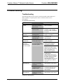
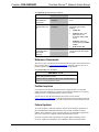
1
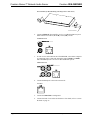
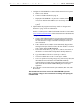
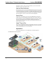
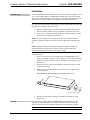
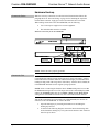
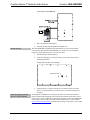
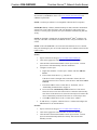
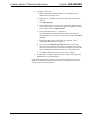
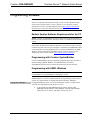
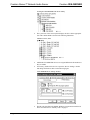
Crestron CEN-ISERVER Crestron iServer™ Network Audio Server Operations Guide This document was prepared and written by the Technical Documentation department at: Crestron Electronics, Inc. 15 Volvo Drive Rockleigh, NJ 07647 1-888-CRESTRON All brand names, product names and trademarks are the property of their respective owners. ©2009 Crestron Electronics, Inc. Crestron CEN-ISERVER Crestron iServer™ Network Audio Server Contents CEN-ISERVER Quick Start iii Introduction ..............................................................................................................................iii Required Equipment...................................................................................................iii Installation ..................................................................................................................iii Crestron iServer™ Network Audio Server: CEN-ISERVER 1 Introduction ............................................................................................................................... 1 Features and Functions ................................................................................................ 1 Applications................................................................................................................. 2 Specifications .............................................................................................................. 3 Physical Description.................................................................................................... 4 Industry Compliance ................................................................................................... 8 Setup .......................................................................................................................................... 9 Network Wiring........................................................................................................... 9 CAT5 Wiring............................................................................................................... 9 Identity Code ............................................................................................................... 9 Installation ................................................................................................................. 10 Hardware Hookup ..................................................................................................... 11 Programming Software ............................................................................................................ 15 Earliest Version Software Requirements for the PC ................................................. 15 Programming with Crestron SystemBuilder.............................................................. 15 Programming with SIMPL Windows ........................................................................ 15 Example Program ...................................................................................................... 17 Uploading and Upgrading........................................................................................................ 18 Establishing Communication..................................................................................... 18 Programs and Firmware ............................................................................................ 19 Program Checks ........................................................................................................ 19 Problem Solving ...................................................................................................................... 20 Troubleshooting......................................................................................................... 20 Reference Documents................................................................................................ 21 Further Inquiries ........................................................................................................ 21 Future Updates .......................................................................................................... 21 Return and Warranty Policies .................................................................................................. 22 Merchandise Returns / Repair Service ...................................................................... 22 CRESTRON Limited Warranty................................................................................. 22 Operations Guide – DOC. 6759B Contents • i Crestron CEN-ISERVER Crestron iServer™ Network Audio Server CEN-ISERVER Quick Start Introduction The following steps are designed to guide you through the basic hookup, configuration and use of a CEN-ISERVER. For detailed instructions on installation and usage, please refer to “Crestron iServer™ Network Audio Server: CEN-ISERVER” on page 1. Required Equipment The following equipment is required to load and run the demo program. • CEN-ISERVER Network Audio Server. • 2-Series control system with CUZ file version 3.155 or later. • Apple iPod®1, 2, 3 • USB cable for connecting CEN-ISERVER to PC 1. The CEN-ISERVER currently supports the iPod Classic only (6th Generation). Future firmware releases will support other iPod models. 2. Except where noted, this document uses the term “iPod” as a general reference to the various versions of iPod produced by Apple Computer, Inc. 3. iPod device not included. Installation Refer to the following diagrams and connect the CEN-ISERVER in the following order. 1. Operations Guide – DOC. 6759B If placing the CEN-ISERVER in a rack, install rack ears as shown in the following diagram (refer to “Rack Mounting” on page 10 for details) and install in the rack. Otherwise, place on shelf. Crestron iServer™ Network Audio Server: CEN-ISERVER ¥ iii Crestron iServer™ Network Audio Server Crestron CEN-ISERVER Ear Attachment for Rack Mounting (this image shows a 1RU device) USE COVER SCREWS 2. Connect AUDIO OUT to amplifier, receiver, or audio distribution system. Make connections via RCA (L and R), CAT5 (CH), or both. AUDIO OUT Port 3. If video is to be delivered from the CEN-ISERVER, select either composite or component video. Connect the appropriate output (YPbPr or COMP) and/or the CH output to a receiver or video distribution system. VIDEO OUT Port 4. Connect the LAN port to the local area network. LAN Port 5. Connect the GROUND to earth ground. 6. Connect the iPod. Close and secure the drawer. For details, refer to “Secure the iPod” on page 12. iv ¥ Crestron iServer™ Network Audio Server: CEN-ISERVER Operations Guide – DOC. 6759B Crestron CEN-ISERVER Crestron iServer™ Network Audio Server Connect the iPod 7. Connect power to the PWR port. In most cases, power is provided from the NET port on other Crestron devices in the equipment rack. Connect Power to the PWR Port 8. Verify power PWR LED and DEVICE LEDs are illuminated. 9. Program the Crestron® system using either: • Standard programming methods such as creating a custom program in SIMPL™ Windows® or Crestron SystemBuilder™. • Use the example program available from the Crestron website (www.crestron.com/exampleprograms) as the foundation for a program containing a CEN-ISERVER. 10. Establish communications with the CEN-ISERVER. Refer to “Establishing Communication” on page 18 for details. Operations Guide – DOC. 6759B Crestron iServer™ Network Audio Server: CEN-ISERVER ¥ v Crestron iServer™ Network Audio Server Crestron CEN-ISERVER 11. Configure the CEN-ISERVER to connect with the network control system. a. DHCP is on by default. b. Connect via USB as described on page 18. c. Display the CEN-ISERVER’s “System Info” window (click the icon) to view and note the IP address (to be used in step 13d below). d. Configure the IP table (this enables communication with the control system). 12. Upload and test the program created in step 8. Refer to “Programs and Firmware” on page 19 for more information. 13. Install and configure Crestron Sync for iTunes on the PC or Mac hosting iTunes®. Crestron Sync is available for download from the Crestron website (www.crestron.com/crestronsync). Follow the instructions to download and configure the software. a. Setup all CEN-ISERVER addresses in Crestron Sync (this should not be done by the end user). Refer to “Install & Configure Crestron Sync for iTunes Software” on page 12 and the Crestron Sync help file for more information. b. If the "Add New Device" window is not automatically displayed after starting Crestron Sync for the first time, right-click inside the “Crestron Sync” window and click Add New Device. c. Enter a name for the device, e.g., My iServer. (This is not the name of the iPod. It is a reference name to help the user identify the iServer). d. Type the IP address of the iServer (from step 11c above). e. Click OK to add the device to the “Crestron Sync” window. f. Test a sync operation. If syncing a large library with an empty iPod, the iPod should be removed from the CEN-ISERVER and directly connected to the PC hosting iTunes. Subsequent minor updates can be done with the iPod in the CEN-ISERVER using the Crestron Sync application. 14. Leave the latest version of the Crestron Sync QuickStart (Doc. 6760) with the end-user. This concludes the Quick Start section of the CEN-ISERVER Operations Guide. Continue reading for more information on installing and operating the CEN-ISERVER. vi ¥ Crestron iServer™ Network Audio Server: CEN-ISERVER Operations Guide – DOC. 6759B Crestron CEN-ISERVER Crestron iServer™ Network Audio Server Crestron iServer™ Network Audio Server: CEN-ISERVER Introduction The CEN-ISERVER provides a very practical and cost-effective network audio server solution utilizing the popular Apple iPod® as its engine1, 2, 3. Designed for shelf or rack mount installation, the CEN-ISERVER provides a permanent housing for the iPod, adding high-speed Ethernet connectivity to enable full integration with a Crestron® control system while still allowing syncing with iTunes® software. 1. The CEN-ISERVER currently supports the iPod Classic only (6th Generation). Future firmware releases will support other iPod models. 2. Except where noted, this document uses the term “iPod” as a general reference to the various versions of iPod produced by Apple Computer, Inc. 3. iPod device not included. Features and Functions . • • • • • • • “Made for iPod” network audio server for use with Apple iPod® Full 2-way touchpanel control of the iPod Sync to iTunes® over Ethernet Buffered audio and video outputs Crestron Home® (CH) CAT5 Balanced AV connectivity Plug-and-play integration with Adagio® systems Single-space 19" rack-mountable Simple Setup Mounting the iPod device into the CEN-ISERVER is as simple as placing it in the front panel docking bay and connecting the docking cable. Once mounted in the CEN-ISERVER, the iPod becomes a permanent component of your entertainment system, although it is easily swapped out at any time to allow for upgrade or repair. Touchpanel Control Integrating the iPod with your Crestron system enables full control and navigation using touchpanels, APADs, keypads, computers, and handheld remotes anywhere Operations Guide – DOC. 6759B Crestron iServer™ Network Audio Server: CEN-ISERVER • 1 Crestron iServer™ Network Audio Server Crestron CEN-ISERVER throughout a residence or office. From any touchpanel, you can search the entire iPod library by genre, artist, album or track. Audio and Video Distribution Buffered outputs on the rear of the CEN-ISERVER enable audio and video signals to be fed from the iPod to your home theater or multiroom distribution system. Discrete composite and component video outputs are included. Both unbalanced and Crestron "CH" CAT5 balanced connections are provided for total compatibility with Adagio® and Crestron Home® systems, as well as with conventional equipment. Sync to iTunes Using USB-over-IP technology, the Crestron CEN-ISERVER allows the iPod to connect with any networked computer running Apple iTunes software without ever having to undock it from the CEN-ISERVER. Syncing the iPod to iTunes works the same as if it were hooked up with a USB cable, affording full capabilities for organizing and transferring your music and video files, podcasts, audio books, and playlists anytime you want. Adagio® Plug-and-Play The Crestron CEN-ISERVER affords easy plug-and-play setup as part of a complete Adagio system. Without any programming, Adagio delivers full access and control of the CEN-ISERVER from every room in the house. Applications The following diagram shows a CEN-ISERVER in a residential application. CEN-ISERVER in a Residential Application 2 • Crestron iServer™ Network Audio Server: CEN-ISERVER Operations Guide – DOC. 6759B Crestron CEN-ISERVER Crestron iServer™ Network Audio Server Specifications Specifications for the CEN-ISERVER are listed in the following table. CEN-ISERVER Specifications SPECIFICATION DETAILS Power Usage 8 Watts (0.34 Amps @ 24 Volts DC), provided by Cresnet or external power supply. Power supply not included. Compatible iPod Models For latest iPod device support information, refer to Crestron True Blue Online Help Answer ID 3325, or contact Crestron True Blue Support; Website URL: www.crestron.com/true_blue_support; NOTE: Supports access to music and video functions only; does not provide access to photo, phone, game, or Web functions. Signal Types: Audio Analog stereo, Crestron ‘CH’ CAT5 Balanced Video Composite, Component (YPbPr), Crestron ‘CH’ CAT5 Balanced Ethernet 10/100BaseT, static IP or DHCP, DNS, full duplex, auto-discovery Minimum 2-Series Control System Update File1,2 Version 3.155 or later Environmental Temperature 41º to 113º F (5º to 45 ºC) Humidity 10% to 90% RH (non-condensing) Heat Dissipation 27 BTU/Hr Enclosure Chassis Aluminum, black matte powder coat finish Faceplate Extruded aluminum, black matte powder coat finish with polycarbonate label overlay Mounting Freestanding or 1U 19-inch rack-mountable (adhesive feet and rack ears included) Dimensions Height 1.80 in (4.57 cm) with feet, 1.70 in (4.32 cm) without feet Width 17.07 in (43.36 cm) without ears, 19.0 in (48.26 cm) with ears Depth 10.43 in (26.49 cm) Weight 4.30 lbs (1.95 kg) Available Accessories ABAR-1 Balanced Audio Receiver 1. The latest software versions can be obtained from the Crestron website. Refer to the NOTE following these footnotes. 2. Crestron 2-Series control systems include the AV2 and PRO2. Consult the latest Crestron Product Catalog for a complete list of 2-Series control systems. Operations Guide – DOC. 6759B Crestron iServer™ Network Audio Server: CEN-ISERVER • 3 Crestron iServer™ Network Audio Server Crestron CEN-ISERVER NOTE: Crestron software and any files on the website are for authorized Crestron dealers and Crestron Authorized Independent Programmers (CAIP) only. New users may be required to register to obtain access to certain areas of the site (including the FTP site). Physical Description This section provides information on the connections, controls and indicators available on your CEN-ISERVER. CEN-ISERVER Physical View (front) CEN-ISERVER Physical View (rear) CEN-ISERVER Overall Dimensions 10.43 in (26.49 cm) 1.70 in (4.32 cm) 17.07 in (43.36 cm) 4 • Crestron iServer™ Network Audio Server: CEN-ISERVER Operations Guide – DOC. 6759B Crestron CEN-ISERVER Crestron iServer™ Network Audio Server CEN-ISERVER Buttons and Ports 3 4 1 2 9 5 6 7 8 10 11 Connectors, Controls & Indicators # CONNECTORS1, CONTROLS & INDICATORS 1 PWR LED (1) Green LED, indicates 24 Volts DC power supplied from Cresnet or external power supply; Power supply not included 2 SYNC LED (1) Yellow LED, indicates when internal iPod is synced to iTunes 3 DEVICE LED (1) Green LED, indicates an iPod is installed and connected 4 DOCKING BAY, DOCKING CABLE & LOCK DESCRIPTION Docking bay holds iPod while connected to CEN-ISERVER; Secures with two thumbscrews (1) 30-pin female I/O plug inside docking bay; Connects to the iPod when installed in the docking bay Lock uses 9/64 Hex screw (located on top of unit) to prevent unwanted removal of iPod; Hex key not included (Continued on following page) Operations Guide – DOC. 6759B Crestron iServer™ Network Audio Server: CEN-ISERVER • 5 Crestron iServer™ Network Audio Server Crestron CEN-ISERVER Connectors, Controls & Indicators (Continued) # CONNECTORS1, CONTROLS & INDICATORS 5 VIDEO OUT DESCRIPTION Composite: (1) RCA female; Composite video output; Output Level: 1 Vp-p nominal; Output Impedance: 75 ohms nominal YPbPr: (3) RCA female; Component (YPbPr) video output; Output Level: 1 Vp-p nominal (Y), 0.7 Vp-p nominal (PbPr); Output Impedance: 75 ohms nominal 2 CH : (1) 8-pin RJ-45 female, shielded; CAT5 balanced video output port; Formats: Composite, component (YPbPr); Connects to any “CH” CAT5 video input port; Maximum Cable Length: 500 ft (152 m) 6 AUDIO OUT L-R: (2) RCA female; Unbalanced stereo linelevel audio output CH3: (1) 8-wire RJ-45 female, shielded; CAT5 balanced stereo audio output port; Connects to any “CH” CAT5 audio input port or bidirectional audio port; Maximum Cable Length: 500 ft (152 m) 7 COMPUTER (1) USB Type B female; USB 2.0 port (cable included) 8 LAN GREEN LED PIN 8 9 YELLOW LED (1) 8-wire RJ-45 with two LED indicators; 10BASE-T/100BASE-TX Ethernet port; Green LED indicates link status; Yellow LED indicates Ethernet activity. PIN SIGNAL PIN SIGNAL 1 2 3 4 TX + TX RC+ N/C 5 6 7 8 N/C RC N/C N/C PIN 1 GROUND (1) 6-32 screw, chassis ground lug. (Continued on following page) 6 • Crestron iServer™ Network Audio Server: CEN-ISERVER Operations Guide – DOC. 6759B Crestron CEN-ISERVER Crestron iServer™ Network Audio Server Connectors, Controls & Indicators (Continued) 1. 2. # CONNECTORS1, CONTROLS & INDICATORS 10 SETUP (LED and button) 11 PWR (1) 2-pin 3.5mm detachable terminal block; 24 Volt DC power input WIRE COLORS (568B) COMPOSITE COMPONENT 1 WHITE/ORANGE + Composite +Y 2 ORANGE - Composite 3 WHITE/GREEN N/A + Pb 4 BLUE N/A + Pr 5 WHITE/BLUE N/A - Pr 6 GREEN N/A - Pb 7 WHITE/BROWN N/A N/A 8 BROWN N/A N/A -Y This eight-pin RJ-45 port provides connectivity to the CNX-BIPAD or or a Crestron device with a CAT5 audio input. This port provides stereo output over CAT5 wiring. Refer to the following table for connector pinouts. PIN Operations Guide – DOC. 6759B Used to setup unit’s IP ID in conjunction with Crestron Toolbox™. An interface connector for the PWR port is provided with the unit. This eight-pin RJ-45 port provides connectivity to a device with a CH input port or a Crestron device with a CAT5 video input. This port provides component or composite balanced output over CAT5 wiring. Refer to the following table for connector pinouts. RJ-45 PIN NUMBER 3. DESCRIPTION WIRE COLORS (568B) AUDIO I/O 1 WHITE/ORANGE + Audio Left Out 2 ORANGE - Audio Left Out 3 WHITE/GREEN + Audio Right Out 4 BLUE N/A 5 WHITE/BLUE N/A 6 GREEN - Audio Right Out 7 WHITE/BROWN N/A 8 BROWN N/A Crestron iServer™ Network Audio Server: CEN-ISERVER • 7 Crestron iServer™ Network Audio Server Crestron CEN-ISERVER Industry Compliance As of the date of manufacture, the CEN-ISERVER has been tested and found to comply with specifications for CE marking and standards per EMC and Radiocommunications Compliance Labelling. NOTE: This device complies with part 15 of the FCC rules. Operation is subject to the following two conditions: (1) this device may not cause harmful interference and (2) this device must accept any interference received, including interference that may cause undesired operation. This equipment has been tested and found to comply with the limits for a Class B digital device, pursuant to part 15 of the FCC Rules. These limits are designed to provide reasonable protection against harmful interference in a residential installation. This equipment generates, uses and can radiate radio frequency energy and if not installed and used in accordance with the instructions, may cause harmful interference to radio communications. However, there is no guarantee that interference will not occur in a particular installation. If this equipment does cause harmful interference to radio or television reception, which can be determined by turning the equipment off and on, the user is encouraged to try to correct the interference by one or more of the following measures: Reorient or relocate the receiving antenna. Increase the separation between the equipment and receiver. Connect the equipment into an outlet on a circuit different from that to which the receiver is connected. Consult the dealer or an experienced radio/TV technician for help. 8 • Crestron iServer™ Network Audio Server: CEN-ISERVER Operations Guide – DOC. 6759B Crestron CEN-ISERVER Crestron iServer™ Network Audio Server Setup Network Wiring When wiring the Ethernet network, consider the following: • Use Crestron Certified Wire. • Use Crestron power supplies for Crestron equipment. • Provide sufficient power to the system. CAUTION: Insufficient power can lead to unpredictable results or damage to the equipment. Please use the Crestron Power Calculator to help calculate how much power is needed for the system (www.crestron.com/calculators). Unlike other Crestron network devices, the CEN-ISERVER does not use Cresnet® for communications between the device and the control system. The CEN-ISERVER requires the use of a high-speed Ethernet connection for control system and PC communications. For information on connecting Ethernet devices in a Crestron system, refer to the latest version of the Crestron e-Control® Reference Guide (Doc. 6052), which is available for download from the Crestron website (www.crestron.com/manuals). CAT5 Wiring Category 5 (CAT5) wiring is a twisted pair cable designed for Ethernet networks. These networks operate at speeds of up to 100 Megabits per second (Mbps) using the 100BASE-T standard. Crestron takes advantage of this specification for a variety of audio and video applications. Crestron recommends using CresCAT®IM (or CresCAT-D) wire for transmitting video signals from the CH port. When using a Crestron wiring solution, the CresCAT-IM (or CresCAT-D) wire can carry audio and video signals up to 500 feet (152 m) (observe distance limitations based upon power consumption for the device in use). For more information, refer to the latest version of the Crestron CAT5 Wiring Reference Guide (Doc. 6137), which is available for download from the Crestron website. Identity Code The IP ID is set within the CEN-ISERVER’s IP table using Crestron Toolbox. For information on setting an IP table, refer to the Crestron Toolbox help file. The IP IDs of multiple CEN-ISERVER devices in the same system must be unique. When setting the IP ID, consider the following: Operations Guide – DOC. 6759B • The IP ID of each unit must match an IP ID specified in the SIMPL™ Windows® program. • Each device using IP to communicate with a control system must have a unique IP ID. Crestron iServer™ Network Audio Server: CEN-ISERVER • 9 Crestron iServer™ Network Audio Server Crestron CEN-ISERVER Installation Rack Mounting The CEN-ISERVER can be mounted in a rack or stacked with other equipment. Two “ears” are provided with the CEN-ISERVER so that the unit can be rack mounted. These ears must be installed prior to mounting. Complete the following procedure to attach the ears to the unit. The only tool required is a #2 Phillips screwdriver. WARNING: To prevent bodily injury when mounting or servicing this unit in a rack, take special precautions to ensure that the system remains stable. The following guidelines are provided to ensure your safety: • When mounting this unit in a partially filled rack, load the rack from the bottom to the top with the heaviest component at the bottom of the rack. • If the rack is provided with stabilizing devices, install the stabilizers before mounting or servicing the unit in the rack. NOTE: If rack mounting is not required, rubber feet are provided for tabletop mounting or stacking. Apply the feet near the corner edges on the underside of the unit. NOTE: Reliable earthing of rack-mounted equipment should be maintained. Particular attention should be given to supply connections other than direct connections to the branch circuit (e.g. use of power strips). To install the ears: 1. There are screws that secure each side of the CEN-ISERVER top cover. Using a #2 Phillips screwdriver, remove the three screws closest to the front panel from one side of the unit. Refer to the diagram following step 3 for a detailed view. 2. Position a rack ear so that its mounting holes align with the holes vacated by the screws in step 1. 3. Secure the ear to the unit with three screws from step 1, as shown in the following diagram. Ear Attachment for Rack Mounting (this image shows a 1RU device) USE COVER SCREWS 4. Stacking Repeat procedure (steps 1 through 3) to attach the remaining ear to the opposite side. Four “feet” are provided with the CEN-ISERVER so that if the unit is not rack mounted, the rubber feet can provide stability when the unit is placed on a flat surface or stacked. These feet should be attached prior to the hookup procedure. NOTE: No more than two CEN-ISERVER units should be stacked. 10 • Crestron iServer™ Network Audio Server: CEN-ISERVER Operations Guide – DOC. 6759B Crestron CEN-ISERVER Crestron iServer™ Network Audio Server Hardware Hookup Connect the Device Make the necessary connections as called out in the illustration that follows this paragraph. Refer to “Network Wiring” on page 9 before attaching the 4-position terminal block connector. Apply power after all connections have been made. When making connections to the CEN-ISERVER, note the following: • Use Crestron power supplies for Crestron equipment. • The included cable cannot be extended. Hardware Connections for the CEN-ISERVER NOTE: For CAT5 connections use Crestron Certified Wire. NOTE: Ensure the unit is properly grounded. Connect the iPod NOTE: Due to the bandwidth limitations of a LAN, the CEN-ISERVER is not recommended for loading an empty iPod with a large music/video library. A direct USB connection between the iTunes PC and the iPod is highly recommended when loading an empty iPod with a large music/video library. After the iPod is loaded, the CEN-ISERVER should be used for regular syncing operations. NOTE: Prior to connecting the iPod, the iPod’s TV Out setting must be set to On the TV Screen setting must be set to the aspect ratio of the connected display (16:9 or 4:3), the TV Signal setting must be set (NTSC or PAL), and the Fit to Screen setting must be set to Off. For instructions, refer to the iPod instruction manual. After all the connections have been made to the CEN-ISERVER, the iPod can be connected to the CEN-ISERVER. To connect the iPod: Operations Guide – DOC. 6759B 1. Open the docking bay by loosening the thumbscrews and sliding the docking bay forward. 2. As shown in the following diagram, connect the iPod to the docking cable located inside the docking bay. The symbol on the interface cable connector must face up as shown. Crestron iServer™ Network Audio Server: CEN-ISERVER • 11 Crestron iServer™ Network Audio Server Crestron CEN-ISERVER Connect iPod to CEN-ISERVER Secure the iPod 3. Place the iPod in the docking bay. 4. Close the docking bay and tighten the thumbscrews. The CEN-ISERVER is equipped with an anti-theft device to prevent unwanted removal of the iPod from the CEN-ISERVER. A 9/64 Hex key (not included) is required to use the anti-theft device. To secure the iPod: 1. Attach the iPod as described above. 2. Locate the locking screw located on the top of the unit as shown in the following illustration. Locking Screw Location (View from Top) LOCKING SCREW 3. Install & Configure Crestron Sync for iTunes Software Using the Hex key, turn the locking screw counterclockwise to lock the drawer. To unlock the drawer, use the Hex key to turn the locking screw clockwise. To complete the installation, Crestron Sync for iTunes (Crestron Sync) software must be installed and configured on the computer that contains the iTunes software. Crestron Sync can be configured to communicate with one or more CEN-ISERVERs in the system. Crestron Sync is available for download from the Crestron website (www.crestron.com/crestronsync). Instructions for using Crestron Sync can be found in the help file. 12 • Crestron iServer™ Network Audio Server: CEN-ISERVER Operations Guide – DOC. 6759B Crestron CEN-ISERVER Crestron iServer™ Network Audio Server NOTE: Crestron Sync software is compatible with Mac OS® X v10.5, Windows XP Service Pack 2, and Windows Vista. Visit www.crestron.com/crestronsync for additional requirements. NOTE: Crestron Sync software is not compatible with PowerPC™ computers. NOTE (Mac Users): VMware, Parallels Desktop for Mac, and other virtualization software may cause connection issues with your iPod device and Crestron Sync software. To ensure proper operation, the system should be restarted using Mac OS X only. NOTE: An iPod that is formatted on an Apple Macintosh® (Mac®) computer will only sync with a Mac. An iPod that is formatted on a PC will sync with either a PC or Mac. NOTE: If the CEN-ISERVER is on a local network and remote access is desired, then port forwarding for ports 41795 and 19540 needs to be enabled on the local and remote routers. For PC: 1. Open a web browser and go to www.crestron.com/crestronsync. 2. Click on the appropriate link for the PC version of Crestron Sync. 3. Click the link to download and install Crestron Sync software. Crestron Sync software will automatically start after installation. 4. Configure Crestron Sync: a. Right-click inside the “Crestron Sync” window and click Add New Device. b. Enter a name for the device, e.g., My iServer. If the device name is changed while connected to iTunes, this will disconnect the iPod. To re-connect, select the device and click Connect Selected. 5. c. Enter the IP address of the Crestron iServer. For details, refer to “Establishing Communication” on page 18. d. Do not select the Automatically Connect check box. This control allows the user to select the Crestron device connection each time they start iTunes. If the check box is selected Crestron Sync will connect the device automatically each time iTunes starts or Crestron Sync starts. e. Click OK to add the device to the “Crestron Sync” window. To add devices, re-open the “Add New Device” window and configure the additional devices as described above. For Mac: Operations Guide – DOC. 6759B 1. Open a web browser and go to www.crestron.com/crestronsync. 2. Click on the appropriate link for the Mac version of Crestron Sync. 3. Click the link to download and install Crestron Sync software. Crestron Sync will not automatically add itself to Startup. This must be done manually one time. Crestron iServer™ Network Audio Server: CEN-ISERVER • 13 Crestron iServer™ Network Audio Server 4. Crestron CEN-ISERVER Configure Crestron Sync: a. Run the application (Launch the Finder, Go to Applications, then double-click Crestron Sync icon). b. Right-click (or Command + left-click) the application icon located in the Dock. c. Click Open at Login. d. If the “Add New Device” window is not automatically displayed upon starting Crestron Sync for the first time, right-click inside the “Crestron Sync” window and click Add New Device. e. Enter a name for the device, e.g., My iServer. If the device name is changed while connected to iTunes, this will disconnect the iPod. To re-connect, select the device and click Connect Selected. 5. f. Enter the IP address of the Crestron iServer. For details, refer to “Establishing Communication” on page 18. g. Do not select the Automatically Connect check box. This control allows the user to select the Crestron device connection each time they start iTunes. If the check box is selected Crestron Sync will connect the device automatically each time iTunes starts or Crestron Sync starts. h. Click OK to add the device to the “Crestron Sync” window. To add devices, re-open the “Add New Device” window and configure the additional devices as described above. For more information, refer to the latest version of the Crestron iServer™ Network Audio Server QuickStart Guide (Doc. 6760) which is available from the Crestron website or the Crestron Sync help file. 14 • Crestron iServer™ Network Audio Server: CEN-ISERVER Operations Guide – DOC. 6759B Crestron CEN-ISERVER Crestron iServer™ Network Audio Server Programming Software Have a question or comment about Crestron software? Answers to frequently asked questions (FAQs) can be viewed in the Online Help section of the Crestron website. To post a question or view questions you have submitted to Crestron’s True Blue Support, log in at http://support.crestron.com. First-time users will need to establish a user account. Earliest Version Software Requirements for the PC NOTE: Crestron recommends that you use the latest software to take advantage of the most recently released features. The latest software is available from the Crestron website. Crestron has developed an assortment of Windows®-based software tools to develop a controlled system. You can create a program to control the CEN-ISERVER control system using the Crestron programming tools Crestron SystemBuilder™ or SIMPL Windows. For the minimum recommended software versions, visit the Version Tracker page of the Crestron website (www.crestron.com/versiontracker). Programming with Crestron SystemBuilder Crestron SystemBuilder is the easiest method of programming but does not offer as much flexibility as SIMPL Windows. For additional details, download SystemBuilder from the Crestron website and examine the extensive help file. Programming with SIMPL Windows NOTE: While SIMPL Windows can be used to program the CEN-ISERVER, it is recommended to use SystemBuilder for configuring a system. SIMPL Windows is Crestron’s premier software for programming Crestron control systems. It is organized into two separate but equally important “Managers”. Configuration Manager Configuration Manager is the view where programmers “build” a Crestron control system by selecting hardware from the Device Library. • Operations Guide – DOC. 6759B To incorporate the CEN-ISERVER into the system, drag the CENISERVER from the Ethernet Control Modules | Ethernet Audio Modules folder of the Device Library and drop it in the System Views. Crestron iServer™ Network Audio Server: CEN-ISERVER • 15 Crestron iServer™ Network Audio Server Crestron CEN-ISERVER Locating the CEN-ISERVER in the Device Library • The system tree of the control system displays the device in the appropriate slot with a default IP ID as shown in the following illustration. C2ENET-1 Device, Slot 8 • Additional CEN-ISERVER devices are assigned different IP ID numbers as they are added. • If necessary, double click a device to open the “Device Settings” window and change the IP ID as shown in the following figure. “CEN-ISERVER Device Settings” Window • The ID code specified in the SIMPL Windows program must match the IP ID of each unit. Refer to “Identity Code” on page 9. 16 • Crestron iServer™ Network Audio Server: CEN-ISERVER Operations Guide – DOC. 6759B Crestron CEN-ISERVER Program Manager Crestron iServer™ Network Audio Server Program Manager is the view where programmers “program” a Crestron control system by assigning signals to symbols. The symbol can be viewed by double clicking on the icon or dragging it into Detail View. Each signal in the symbol is described in the SIMPL Windows help file (F1). Example Program An example program for the CEN-ISERVER is available from the Crestron website (www.crestron.com/exampleprograms). Operations Guide – DOC. 6759B Crestron iServer™ Network Audio Server: CEN-ISERVER • 17 Crestron iServer™ Network Audio Server Crestron CEN-ISERVER Uploading and Upgrading Crestron recommends using the latest programming software and that each device contains the latest firmware to take advantage of the most recently released features. However, before attempting to upload or upgrade it is necessary to establish communication. Once communication has been established, files (for example, programs or firmware) can be transferred to the control system (and/or device). Finally, program checks can be performed (such as changing the device ID or creating an IP table) to ensure proper functioning. Establishing Communication Use Crestron Toolbox for communicating with the CEN-ISERVER; refer to the Crestron Toolbox help file for details. There are two methods of communication. USB NOTE: Required for initial setup of Ethernet parameters. USB Communication PC RUNNING CRESTRON TOOLBOX TCP/IP USB CEN-ISERVER • The COMPUTER port on the CEN-ISERVER connects to the USB port on the PC via the included Type A to Type B USB cable. • Use the Address Book in Crestron Toolbox to create an entry using the expected communication protocol (USB). When multiple USB devices are connected, identify the CEN-ISERVER by entering “CEN-ISERVER” in the Model textbox, the unit’s serial number in the Serial textbox or the unit’s hostname in the Hostname textbox. The hostname can be found in the “System Info” window in the section marked Ethernet however, communications must be established in order to see this information in the “System Info” window. • icon); Display the CEN-ISERVER’s “System Info” window (click the communications are confirmed when the device information is displayed. NOTE: Required for operation with a Crestron control system. Ethernet Communication PC RUNNING CRESTRON TOOLBOX • ETHERNET CN-ISERVER Establish USB communication between the CEN-ISERVER and PC. 18 • Crestron iServer™ Network Audio Server: CEN-ISERVER Operations Guide – DOC. 6759B Crestron CEN-ISERVER Crestron iServer™ Network Audio Server • Enter the IP address, IP mask and default router of the CEN-ISERVER via the Crestron Toolbox (Functions | Ethernet Addressing); otherwise enable DHCP. • Confirm Ethernet connections between CEN-ISERVER and PC. If connecting through a hub or router, use CAT5 straight through cables with 8-pin RJ-45 connectors. Alternatively, use a CAT5 crossover cable to connect the two LAN ports directly without using a hub or router. • Use the Address Book in Crestron Toolbox to create an entry for the CEN-ISERVER with the CEN-ISERVER’s TCP/IP communication parameters. • Display the “System Info” window (click the CEN-ISERVER entry. icon) and select the Programs and Firmware Program or firmware files may be distributed from programmers to installers or from Crestron to dealers. Firmware upgrades are available from the Crestron website as new features are developed after product releases. One has the option to upload programs via the programming software or to upload and upgrade via the Crestron Toolbox. For details on uploading and upgrading, refer to the SIMPL Windows help file or the Crestron Toolbox help file. SIMPL Windows If a SIMPL Windows program is provided, it can be uploaded to the control system using SIMPL Windows or Crestron Toolbox. Firmware Check the Crestron website to find the latest firmware. (New users may be required to register to obtain access to certain areas of the site, including the FTP site.) Upgrade CEN-ISERVER firmware via Crestron Toolbox. • Establish communication with the CEN-ISERVER and display the “System Info” window. • Select Functions | Firmware… to upgrade the CEN-ISERVER firmware. Program Checks icon) and Using Crestron Toolbox, display the “System Info window (click the select the Functions menu to display actions that can be performed on the CEN-ISERVER. Be sure to use Crestron Toolbox to create the CEN-ISERVER IP table. Omit this item for control systems. • Select Functions | IP Table Setup. • Add, modify or delete entries in the IP table. The CEN-ISERVER can have only one IP table entry. • A defined IP table can be saved to a file or sent to the device. Edit the control system’s IP table to include an entry for the CEN-ISERVER. The entry should list the CEN-ISERVER’s IP ID (specified on the CEN-ISERVER’s IP table) and the internal gateway IP address 127.0.0.1. Operations Guide – DOC. 6759B Crestron iServer™ Network Audio Server: CEN-ISERVER • 19 Crestron iServer™ Network Audio Server Crestron CEN-ISERVER Problem Solving Troubleshooting The following table provides corrective action for possible trouble situations. If further assistance is required, please contact a Crestron customer service representative. CEN-ISERVER Troubleshooting TROUBLE POSSIBLE CAUSE(S) CORRECTIVE ACTION Device is not receiving power from a Crestron power source. Use a Crestron power source. Verify connections. Device is not receiving sufficient power. Use the Crestron Power Calculator to help calculate how much power is needed for the system. PWR LED does not illuminate. CEN-ISERVER is not receiving power. Verify that the correct power supply is connected. DEVICE LED does not illuminate. The iPod is not properly connected to the CEN-ISERVER. Verify that an iPod is properly connected to the CEN-ISERVER. SYNC LED does not illuminate CEN-ISERVER is not syncing with iTunes Verify that Crestron Sync is properly configured. iPod is not processing commands from the control system. The CEN-ISERVER is not communicating with the control system. Verify that CEN-ISERVER and control system’s Ethernet connections are correct. Device does not function. Verify that CEN-ISERVER’s IP table lists the master control system with an IP ID matching the IP ID specified in the SIMPL Windows program. Verify that the control system’s IP table lists the CEN-ISERVER with an IP ID matching the IP ID specified in the SIMPL Windows program. The entry should list the CEN-ISERVER’s IP ID and the internal gateway IP address 127.0.0.1. No audio from CEN-ISERVER. No video from CEN-ISERVER. CEN-ISERVER audio outputs are incorrectly connected. Correctly connect CEN-ISERVER audio outputs. Headphones are connected to iPod’s headphone jack. Verify that headphones are not connected to the iPod prior to connecting the iPod to the CEN-ISERVER. CEN-ISERVER video outputs are incorrectly connected. Correctly connect CEN-ISERVER video outputs. (Continued on following page) 20 • Crestron iServer™ Network Audio Server: CEN-ISERVER Operations Guide – DOC. 6759B Crestron CEN-ISERVER Crestron iServer™ Network Audio Server CEN-ISERVER Troubleshooting (Continued) TROUBLE POSSIBLE CAUSE(S) No video from CEN-ISERVER. CORRECTIVE ACTION iPod is incorrectly configured. Verify video output settings on iPod. iPod is incorrectly configured. Disconnect the iPod and verify the following iPod Video Settings: (Continued) Video output is distorted and/or cut off. Loss of functionality due to electrostatic discharge. Improper grounding. • TV Out: On • TV Screen: Set to the aspect ratio of the connected display (16:9 or 4:3) • TV Signal: Set to the correct signal type (NTSC or PAL) • Fit to Screen: Off Check that all ground connections have been made properly. Reference Documents The latest version of all documents mentioned within the guide can be obtained from the Crestron website (www.crestron.com/manuals). This link will provide a list of product manuals arranged in alphabetical order by model number. List of Related Reference Documents DOCUMENT TITLE CAT5 Wiring Reference Guide Crestron iServer™ Network Audio Server QuickStart Guide Crestron e-Control Reference Guide Further Inquiries If you cannot locate specific information or have questions after reviewing this guide, please take advantage of Crestron's award winning customer service team by calling Crestron at 1-888-CRESTRON [1-888-273-7876]. You can also log onto the online help section of the Crestron website (www.crestron.com/onlinehelp) to ask questions about Crestron products. First-time users will need to establish a user account to fully benefit from all available features. Future Updates As Crestron improves functions, adds new features and extends the capabilities of the CEN-ISERVER, additional information may be made available as manual updates. These updates are solely electronic and serve as intermediary supplements prior to the release of a complete technical documentation revision. Check the Crestron website periodically for manual update availability and its relevance. Updates are identified as an “Addendum” in the Download column. Operations Guide – DOC. 6759B Crestron iServer™ Network Audio Server: CEN-ISERVER • 21 Crestron iServer™ Network Audio Server Crestron CEN-ISERVER Return and Warranty Policies Merchandise Returns / Repair Service 1. No merchandise may be returned for credit, exchange or service without prior authorization from CRESTRON. To obtain warranty service for CRESTRON products, contact an authorized CRESTRON dealer. Only authorized CRESTRON dealers may contact the factory and request an RMA (Return Merchandise Authorization) number. Enclose a note specifying the nature of the problem, name and phone number of contact person, RMA number and return address. 2. Products may be returned for credit, exchange or service with a CRESTRON Return Merchandise Authorization (RMA) number. Authorized returns must be shipped freight prepaid to CRESTRON, 6 Volvo Drive, Rockleigh, N.J. or its authorized subsidiaries, with RMA number clearly marked on the outside of all cartons. Shipments arriving freight collect or without an RMA number shall be subject to refusal. CRESTRON reserves the right in its sole and absolute discretion to charge a 15% restocking fee plus shipping costs on any products returned with an RMA. 3. Return freight charges following repair of items under warranty shall be paid by CRESTRON, shipping by standard ground carrier. In the event repairs are found to be non-warranty, return freight costs shall be paid by the purchaser. CRESTRON Limited Warranty CRESTRON ELECTRONICS, Inc. warrants its products to be free from manufacturing defects in materials and workmanship under normal use for a period of three (3) years from the date of purchase from CRESTRON, with the following exceptions: disk drives and any other moving or rotating mechanical parts, pan/tilt heads and power supplies are covered for a period of one (1) year; touchscreen display and overlay components are covered for 90 days; batteries and incandescent lamps are not covered. This warranty extends to products purchased directly from CRESTRON or an authorized CRESTRON dealer. Purchasers should inquire of the dealer regarding the nature and extent of the dealer's warranty, if any. CRESTRON shall not be liable to honor the terms of this warranty if the product has been used in any application other than that for which it was intended or if it has been subjected to misuse, accidental damage, modification or improper installation procedures. Furthermore, this warranty does not cover any product that has had the serial number altered, defaced or removed. This warranty shall be the sole and exclusive remedy to the original purchaser. In no event shall CRESTRON be liable for incidental or consequential damages of any kind (property or economic damages inclusive) arising from the sale or use of this equipment. CRESTRON is not liable for any claim made by a third party or made by the purchaser for a third party. CRESTRON shall, at its option, repair or replace any product found defective, without charge for parts or labor. Repaired or replaced equipment and parts supplied under this warranty shall be covered only by the unexpired portion of the warranty. Except as expressly set forth in this warranty, CRESTRON makes no other warranties, expressed or implied, nor authorizes any other party to offer any warranty, including any implied warranties of merchantability or fitness for a particular purpose. Any implied warranties that may be imposed by law are limited to the terms of this limited warranty. This warranty statement supersedes all previous warranties. Trademark Information All brand names, product names and trademarks are the sole property of their respective owners. Windows is a registered trademark of Microsoft Corporation. Windows95/98/Me/XP/Vista and WindowsNT/2000 are trademarks of Microsoft Corporation. iPod, iTunes and Mac OS are trademarks of Apple Computer, Inc., registered in the U.S. and other countries. PowerPC is a trademark of International Business Machines Corporation. 22 • Crestron iServer™ Network Audio Server: CEN-ISERVER Operations Guide – DOC. 6759B Crestron CEN-ISERVER Crestron iServer™ Network Audio Server This page is intentionally left blank. Operations Guide – DOC. 6759B Crestron iServer™ Network Audio Server: CEN-ISERVER • 23 Crestron Electronics, Inc. 15 Volvo Drive Rockleigh, NJ 07647 Tel: 888.CRESTRON Fax: 201.767.7576 www.crestron.com Operations Guide – DOC. 6759B (2022860) 02.09 Specifications subject to change without notice.