1
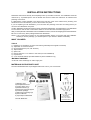
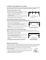
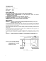
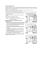
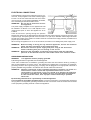
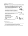
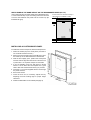
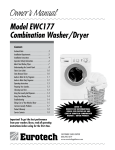
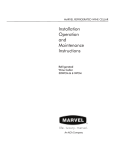
IMPORTANT INFORMATION Revised Dishwasher Installation Instructions To obtain a revised copy of the entire Dishwasher Users Manual, go to www.eurotechappliances.com. SAVE THESE INSTRUCTIONS FOR FUTURE REFERENCE SPECIAL EDITION 11-20-02 INSTALLATION INSTRUCTIONS Read these instructions carefully and completely before you install the machine. The installation should be carried out by a qualified person who is familiar with all local codes and ordinances for electrical and plumbing connections. If a dishwasher is being installed in this area for the first time, most of the cabinet work, plumbing, and electrical has to be done before you move the machine into place. If you are replacing an old dishwasher, you must check the plumbing connection and wiring before you move the new dishwasher into place. A built-in dishwasher must be enclosed on the top, both sides and the back. The best place for your dishwasher is in the kitchen near the sink. This makes it easier to connect the water and drain supply lines. After you have placed the dishwasher near the installation location, remove the wrappings from the dishwasher. Be sure to remove any items packaged inside the dishwasher. NOTE: It is a good idea to inspect for any shipping damage before you proceed with the installation. Should you find any damage, you should report it to your dealer or builder immediately. WHAT YOU NEED TOOLS 1) 2) 3) 4) 5) 6) 7) 8) Phillips No. 2 screwdriver or power screwdriver (preferably with magnetic screw bits) Adjustable 10” crescent wrench Open-ended wrench (1/2", 3/8” and 5/8") Tape measure Spirit level Electric drill with 1-1/2”” drill bit or hole saw (for new installations) Keyhole saw 2-1/2” Squeeze Clamps (for EDW194E door panel installation only) MATERIALS NEEDED ♦ Shut-off valve and fittings for water supply line MATERIALS SUPPLIED WITH UNIT The items illustrated below are packaged inside each unit for your convenience. Hardware Package Contents 1) Warrranty card 2) Data plate/serial card 3) Cutlery caddy cover * 4) Moisture barriers (2) 5) Drain hose high loop support 6) Hardware package 7) Slide cups for levelling legs 8) Owner's Manual 9) Top fill strip for EDW194E *Not with EDW132C 2 Two 1-1/8” screws with sleeves Four 3/4” screws Four 1-1/2” screws One rubber washer CABINET OPENING DIMENSIONS After determining where the water supply line will enter under the sink, drill a 1-1/2" (38 mm) access hole. The water line inlet valve is on the right rear of the machine. 32" to 35" 813 to 890 mm The electrical and water supplies should enter through the area indicated by the shading on the illustration at right. They should come through the right side of the machine, a maximum of 2” (50 mm) from the back wall and 6-1/4” to 8-1/4” (159–210 mm) from the floor, depending on the underneath cabinet height. 2" 50 mm 6-1/4" to 8-1/4" 159 to 210 mm 23 60 -15 8 /16 m m " Height Width Depth Measurements US Metric 32"–35" 813–890 mm 24" 610 mm 23-15/16" 608 mm 24" 610 mm MOISTURE BARRIER Among the materials supplied with your unit are two strips of moisture resistant material (moisture barriers). One of these is intended to be affixed underneath the front edge of the cabinet to prevent possible moisture damage. The other is for a custom wood panel (EDW194E only). If you intend to use a moisture barrier on the cabinet, you should affix it to the cabinet before you install the dishwasher. INSTALLING THE TOP FILL STRIP ON MODEL EDW194E If you have Model EDW194E, you will need to install the fill strip before you place the dishwasher inside the cabinet. To do this, follow the instructions below: 1. Center the fill strip on top of the installation lip on the front edge of the unit. 2. If the fill strip is wider than the cabinet opening, use a coarse sandpaper or straight edge hack saw to trim one end. 3. Using 2-1/2” squeeze clamps, secure the fill strip to the installation lip, as illustrated below. 4. Fasten the fill strip to the dishwasher using the four 3/4” screws supplied with the unit in the holes on the installation lip. 5. Remove the clamps. 3 ADJUSTING THE LEVELING LEGS Before you slide the unit under the cabinet, you should adjust the levelling legs to within 1/8” of the opening height. The four leveling legs should be adjusted by unscrewing the leg out to the length required. The final height adjustment should be made after the unit is in place under the cabinet. When the feet are properly adjusted, tighten the locking nuts to the base pan. (The machine may have an inclination of 2° maximum without affecting its performance.) WARNING! Levelling leg Never lay the dishwasher on its front or side. When necessary, lay the unit on its back. It is advisable to lay the unit on a tarp or blanket so as not to scratch or damage the floor or the dishwasher. Locking nut MOVING THE MACHINE INTO PLACE WARNING! Make sure you put the slides cups under the legs to prevent damaging the floor or unit when you slide it into place (see page 6). 1. Remove the zip tie holding the hoses and power supply cord in place on the back of the unit, as illustrated at right. 2. Position the machine in front of the cabinet opening. 3. Pull out the drain hose to ensure there are no sharp bends. 4. Start to feed water, drain lines, and electric cord (if necessary) into the access hole in the cabinet. 5. Grip the unit at the top or side edges and gently slide the unit into the dishwasher opening using the slide cups provided with the unit. WARNING! Never use your knee or shoulder to push the unit in place. You could damage the dishwasher. 6. Check the level and make adjustments if necessary. (See above.) WARNING! Be careful of sharp edges. OPENING THE EDW194E CUSTOM DOOR To open the door panel on the EDW194E, insert your fingers into the rectangular slots on each side of the door and pull. 4 FASTENING THE DISHWASHER TO THE CABINET It’s necessary to fasten the dishwasher to the cabinet so it won’t tilt when the door is opened or if something heavy is placed on the door. Use only the screws provided with the machine. The dishwasher can be fastened to the cabinet on the top, at the sides, or both, depending on the type of installation. STANDARD CABINET INSTALLATIONS For a standard cabinet installation, you should mount the dishwasher at the top. To do this, follow the instructions below: 1. Use the four 3/4” screws provided with the unit to mount the dishwasher to underneath the cabinet top. 2. Insert the screws through the four holes on the top installation lip and tighten securely. 3. When the machine is properly attached, check that the feet are tight against the floor and the machine is level. Top Fastening This method is for standard installations only. SOLID SURFACE COUNTER TOP INSTALLATIONS If you have a solid surface countertop that will not accommodate screws, mount the dishwasher to the cabinet using the side mount holes. To do this, follow the instructions below: 1. Remove the white plugs from the side holes and use a “center punch” to assist in starting the screws. 2. Insert the two mounting screws with sleeves provided with the unit into the side holes and tighten the screw securely. 3. Cover the screw heads with the plastic plugs provided with the machine. 4. When the machine is properly attached, check that the feet are tight against the floor and that the machine is level. Side Fastening Use this method only for solid surface counter tops, such as marble. EDW194E WITH A TOP FILL STRIP INSTALLATIONS Model EDW194E installations with a top fill strip should be mounted to the cabinet on the sides. NOTE: Do not fasten the dishwasher to the cabinet until after you have installed the custom door panel. To do this installation, follow the steps below: 1. Install the fill strip as explained on page 6. 2. Remove the white plugs from the side holes and use a “center punch” to assist in starting the screws. 3. Insert the two mounting screws with sleeves provided with the unit into the side holes and tighten securely. 4. Cover the screw heads with the plastic plugs provided with the machine. 5. When the machine is properly attached, check that the feet are tight against the floor and that the machine is level. Top fill strip Side Fastening Model EDW194E This method is for EDW194E installations with a top fill strip. INSTALLING THE TOE KICK You will have to adjust the toe kick bracket depth to allow for the thickness of the toe kick. To do this, first measure the thickness of the toe kick. Then press the spring tab on the sides of the base pan toward the outside of the machine and carefully pull or push the bracket to the required depth less the thickness of the toe kick. Make sure the toe kick bracket is securely inside the guides on the base pan. Once you have adjusted the toe kick bracket to the desired depth, you can install the toe kick, as follows: 1. If you have not done so, remove the toe kick from inside or on top of the unit. 2. Positioning the toe kick at the edge of the access panel, slide the toe kick up behind the access panel then let it slide to the floor. 3. Screw the toe kick to the toe kick brackets. 5 TECHNICAL DATA Water pressure Power Heating element Max loading 18-176 psi 110–120 v, 60 Hz 1200 w 1450 w EASY CONNECTION Your Eurotech comes with everything you need for an easy, problem-free installation: n PEX tubing with 3/8” compression fitting—This tubing has a 50-year spec life. It fits American dishwasher water supply valves. n Drain hose—Corrugated drain hose and holder to form a high loop. n Electrical cord and plug—110-120 volts, 15 amp cord supplied with unit. WARNING! Do not use an extension cord for this appliance. WATER SUPPLY WARNING! Plumbing connections must comply with applicable sanitary, safety and plumbing codes in your area. The dishwasher comes with a 5-foot PEX water supply line that has a 3/8" NPT female connection. Be sure to insert the black rubber washer (enclosed in the hardware package) into the PEX hose connection before you attach it to the water supply. The electrical and water supplies should come through the right side of the machine, a maximum of 2” (50 mm) from the back wall and 6-1/4” to 8-1/4” (159–210 mm) from the floor, depending on the underneath cabinet height. For service convenience, a shut-off valve (not supplied) should be installed in the water supply line in an easily accessible location, such as, beneath the sink. It is important that the water supply line and the shut-off valve have a sufficient flow volume. At least 3 gallons (12 liters) per minute must be able to pass through the line. The water pressure should be 18-176 psi. WARNING! In order to prevent heat damage to the inlet valve, all solder connections must be made before the water line is connected to the dishwasher. NOTE: Be sure to run the PEX water supply line, drain line, and power supply cord through the hole to sink compartment before moving the dishwasher into position. 6 (1) Water supply (2) Water supply valve (not supplied) DRAIN CONNECTIONS Eurotech provides a 5/8” (17 mm) corrugated drain hose with a drain line holder to form a high loop. If additional drain hose is needed, please purchase an additional Eurotech drain hose and join it to the provided hose with a 5/8” (17 mm) copper tube. NOTE: Do not use any fittings anywhere in the drain line that are less than 5/8" (17 mm) ID. The access hole for the drain line should be 1-1/2" (38 mm). The high loop is necessary for proper draining and should be located as close to the dishwasher as possible. There are three ways to connect the drain supply line, as shown in the illustrations at right: A) Typical connection to sink plumbing before trap (high loop drain) A) Typical connection to sink plumbing before trap (high loop drain) B) Connection to air gap then to the trap. C) Connection to waste disposer with air gap NOTE: Don’t forget to remove the knockout or plug from the disposer fitting. IMPORTANT THINGS TO KNOW ABOUT DRAIN CONNECTIONS: ♦ Failure to provide the proper drain connection height (minimum of 20" (508 mm)) above the bottom of the dishwasher base) or a 20" (508 mm) high loop will result in improper drainage, which will damage the machine. B) Connection to air gap then to the trap. ♦ No part of the drain hose should be higher than 35" (889 mm) from the bottom of the dishwasher. ♦ The hose must not be drawn straight to a floor well or its equivalent because it might function as a siphon and empty the machine. ♦ The drain hose can be extended to a maximum length of 10 feet (3048 mm). Joints and jointed tubes, if any, must have a minimum 5/8" (17 mm) ID. ♦ If the drain line is going to be connected to a waste disposer, be sure to remove the knockout or plug from the fitting on the disposer before connecting the drain line. When the installation is ready, open the supply valve and let the pressure act for a while. Then check that all connections are tight and there are no leaks. 10 C) Connection to waste disposer with air gap. ELECTRICAL CONNECTIONS The dishwasher comes with an electrical cord for 110– 120 volts, 15 amp supplied. This cord should be plugged into the 110-120 volt outlet under the sink. If the cord is not long enough, or if a hard-wire installation is needed, see “Connecting An Electrical Cable” below. WARNING! Do not use an extension cord for this appliance. The power-supply receptacle for the appliance should be installed in a cabinet or on a wall adjacent to the undercounter space in which the appliance is to be installed. There should be an opening through the partition between the opening for the dishwasher and the area under the sink that is large enough for the power cord to pass through. This opening should not be more than 1-1/2” (38 mm) in diameter and the edges should be smooth and rounded. If the partition is metal it should be covered with an edge protector provided for this purpose by the manufacturer. When moving the appliance into or out of the cabinet, be careful not to damage the power-supply cord. WARNING! WARNING! WARNING! Before working on wiring for any electrical appliance, be sure the electrical power has been turned off at the breaker/fuse box. Disconnect electrical power supply and place a tag at the disconnect switch indicating that you are working on the circuit. Electrical and grounding connections must comply with the applicable portions of the national electrical code and/or other local electrical codes. GROUNDING INSTRUCTIONS WARNING! This appliance must be properly grounded. A) Grounding instructions for a grounded, cord-connected appliance In the event of malfunction or breakdown, grounding will reduce the risk of electric shock by providing a path of least resistance for electric current. This appliance is equipped with a cord having an equipmentgrounding conductor and a grounding plug. The plug must be plugged into an appropriate outlet that is properly installed and grounded in accordance with all local codes and ordinances. WARNING! Improper connection of the equipment-grounding conductor can result in a risk of electric shock. Check with a qualified electrician or service representative or personnel if you are in doubt as to whether the appliance is properly grounded. Do not modify the plug provided with the appliance. If it will not fit the outlet, have a proper outlet installed by a qualified electrician. B) Grounding instructions for a permanently connected appliance: This unit must be grounded to operate properly. It must be connected to a grounded metal, permanent wiring system or an equipment-grounding conductor must be run with the circuit conductors and connected to the equipment-grounding terminal or lead of the appliance. 8 CONNECTING AN ELECTRIC CABLE If the cord is not long enough, or if a hard-wire installation is needed, follow the steps below to complete the electrical connection. WARNING! Before working on wiring for any electrical appliance, be sure the electrical power has been turned off at the breaker/fuse box. 1. Remove the access panel by removing the two screws on each side of the access panel that hold the fill strips in place. Next, remove the two screws underneath the panel that hold it against the guard plate. After you have removed all four screws, slide the access panel down below the two tabs at the top to remove it. 2. Remove the toe kick brackets by holding the small metal spring tab on the outer edge of the base pan toward the outside of the machine. Continue holding the tab as you pull straight out on the bracket. (Note: It may be stubborn because it’s in guide slots on the base pan.) See page 10 for instructions on how to adjust the toe kick brackets. 3. Remove the guard plate by removing the three phillips-head screws that hold the guard plate in place, two on the upper/underneath side and two on the front. After the screws are removed, grip the bottom of the guard plate and pull it toward you to remove it. You can now access the inlet valve, electrical connection, and drain pump and hose. 4. Remove the supplied power cord. 5. Connect supply cable with a UL-listed strain relief bushing (if nonmetallic cable is to be used). 6. Connect branch circuit white lead to white lead on main terminal block, as illustrated at right. 7. Connect branch circuit black lead to brown lead on main terminal block, as illustrated. 8. Connect ground wire to ground on terminal block, as illustrated. 9. Replace the guard plate. 10. Replace the toe kick brackets and toe kick (see page 9). Toe kick bracket Making the Connection TESTING FOR LEAKS 1. Turn on the water supply and check for leaks. 2. Turn the power on at breaker/fuse box and test the dishwasher operation by running a Rinse cycle. (This should take about four minutes.) 3. Turn off the electrical power and check for leaks under the dishwasher and sink. 4. Make sure that no kinks have developed in the drain lines. If there are no leaks and the dishwasher seems to be working properly, continue with the installation. 9 FITTING THE EDW194E ONE-PIECE CUSTOM DOOR PANEL Model EDW194E can only be installed with a one-piece custom door panel that extends from the toe kick to the counter top. The unit comes with everything needed to make installing the door panel easy. The door is predrilled for the panel’s mounting screws. To order a one-piece door, contact your dealer. The part numbers are listed below: White 720356200 Black 720356300 Bisque 720356400 Stainless Steel 720356500 ITEMS PROVIDED WITH THE ONE-PIECE DOOR PANELS These items are supplied with the doors: ♦ One-piece door ♦ Color-coordinated toe kick ♦ Door handle ♦ Handle support bracket ♦ Two 1/2” machine screws for handle ♦ Two 1/2” sheet metal screws for toe kick INSTALLING THE ONE-PIECE CUSTOM DOOR PANEL Before fitting the custom panel, the dishwasher must be installed underneath the cabinet. For this installation, we recommend that you install the 2” fill strip (see page 6) that comes with the unit to hide the top of the dishwasher and further reduce water noise. NOTE: Do not fasten the dishwasher to the cabinet until after you have installed the door panel. 1. Remove the custom panel and parts from the packaging. 2. Move the insulation on the back of the custom panel. 3. Slide the handle support bracket to the inside top of the panel. 4. Insert the screws through the support bracket and the panel. 5. Fit the door handle to the screws and secure tightly. 6. Remove the rubber gaskets from inside the dishwasher door and discard. 7. Remove the second and fourth screws from the inside top of the dishwasher door (as illustrated) and discard. 8. With the door slightly open, position the panel with the holes in alignment with the door holes and secure it in place with 2-12” squeeze clamps on both sides. 9. Insert the 1-1/2” screws partially through the dishwasher door. 10. Loosen the clamp on one side enough to align the screws with the holes in the panel. 11. Secure the screws. 2nd screw Dishwasher door 4th screw 12. Repeat steps 9 and 10 for the other side. 13. Close the door and, if necessary, adjust for square by adjusting the front levelling legs for proper height clearance. 14. Fasten the dishwasher to the cabinet (see page 9). 10 With this installation, the custom panel extends 1-13/16” inches above the dishwasher control panel, as illustrated. BUILDING A CUSTOM WOOD DOOR PANEL FOR MODEL EDW194E If you prefer, you can build a custom wood door panel for this model to match the cabinets. CUSTOM WOOD PANEL DIMENSIONS Width: Height: 23-3/8” (595 mm) 28-1/4 min. to 30-1/16” max. (718 mm–764 mm) (Measured from the top of the panel to the lower edge of the kitchen cabinet.) Thickness: 1/4” (6 mm) minimum to 3/4” (19 mm) maximum Weight: Up to 22 lb. NOTE: Screws for mounting custom wood panels less than 3/4” are not supplied with the unit. MOISTURE BARRIER Among the materials supplied with your unit are two strips of moisture resistant material (moisture barriers). One of these is intended to be affixed along the bottom edge of the back of the wood panel to prevent possible moisture damage. You should affix the moisture barrier to the panel before you attach the panel to the dishwasher door. CUSTOM WOOD PANELS THAT EXTEND TO THE CABINET TOP (30-1/16”) With this installation, the custom panel extends 1-13/16” inches above the dishwasher control panel, as illustrated at right. This installation also leaves a 2” gap between the top of the dishwasher and the cabinet. We recommend that you install the 2” fill strip that comes with the unit between the upper edge of the dishwasher and the counter to hide the top of the dishwasher and further reduce water noise. Panel extends from toe kick to cabinet top 30-1/16" 764 mm 2-inch fill strip 23-3/8" 595 mm toe kick toe kick NOTE: You will also need to build a custom wood toe kick to match the wood door panel. 11 WOOD PANELS THE SAME HEIGHT AS THE DISHWASHER DOOR (23-1/4”) Custom-built 2-inch decorative fill strip or cutting board (not available to order) 28-1/4" 718 mm If the custom panel is the same height as the dishwasher door, a 2” decorative fill strip or pull-out cutting board must be used to fill the area between the panel and the counter top (as illustrated at right). 23-3/8" 595 mm toe kick INSTALLING A CUSTOM WOOD PANEL To install the custom wood panel, follow the steps below. 1. Attach the handle (A) to the wood panel. (It is best to use a handle instead of a knob.) 2. Remove the second and fourth screws (B and C) from the inside top of the dishwasher door and discard. 3. With the door slightly open, position the wood panel with the holes in alignment with the door and secure it in place with 2-12” squeeze clamps on both sides. 4. If you are installing a 30-1/16” high panel, it should extend 1-13/16” above the control panel. It’s a good idea to take this measurement before you proceed. 5. Insert the 1-1/2” screws supplied with the unit through the panel and door. 6. Secure the screws. 7. Close the door and, if necessary, adjust level by adjusting the front levelling legs for proper height clearance. 8. Fasten the dishwasher to the cabinet (see page 9). 12