1
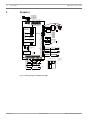
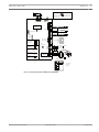
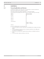
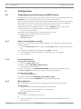
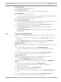
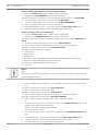
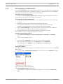
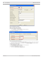
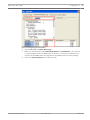
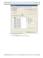
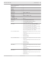
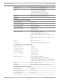
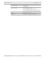
AMAX 2100 / 3000 / 4000
en
Quick Start Guide
AMAX 2100 / 3000 / 4000
Table of Contents | en
3
Table of contents
1
Graphics
4
2
Safety
6
3
Short information
8
4
Installation
9
4.1
Connecting Modules and Devices
5
Configuration
10
5.1
Programming and Operating the AMAX System
10
5.1.1
Option: Changing Menu Language
10
5.1.2
Accessing the Menus
10
5.1.3
Menu Navigation
10
5.1.4
Programming the AMAX System
11
5.1.5
PC Programming via USB Interface
13
6
Technical Data
18
Bosch Sicherheitsysteme GmbH
Quick Start Guide
9
2014.03 | 01 |
4
en | Graphics
1
AMAX 2100 / 3000 / 4000
Graphics
R
B
G
R
B
G
Y
_ 900mA
AUX 1: <
_ 900mA
AUX 2: <
TIP
TH
RH RING
Y
AUX1 AUX2 AUX2 AUX1
+12V +12V -
Bosch Option
AUX Power
_ 900mA
Bus 2 <
Transformer
Keypads:
GND
AC
AC
1=
2=
IUI-AMAX4-TEXT
IUI-AMAX3-LED16 3 =
IUI-AMAX3-LED8
4=
+
18VAC@50VA
Battery
12V 7Ah
_ 18Ah
12V <
230V ~50Hz
230mA
Fuse 1 A
5-16 Inst. Guide
Keypads:
IUI-AMAX-LED8
IUI-AMAX-LCD8
Bosch Option
_ 900mA
Bus 1 <
1=
2=
I/O Moduls:
DX2010
DX3010
DX4010
Adr. 103 - 108
Adr. 150 - 151
Adr. 253
Communicators:
DX4020G
B426
Adr. 134
Adr. 134(6) / 250(9)
RF Receiver:
RF3227E
RFRC-OPT
Y
Y
G
G
B
B
R
R
+12V
P0+4
+12V
P0+3
+12V
P0+
COM
P0-2
COM
P0-1
PO+4: _
<
_
PO+3: <
_
PO -2: <
_
PO -1: <
L16
1=
1= (1)
750mA
750mA
500mA
500mA
supervised
100 Ω - 2,2 k
COM
L15
Factory
Default
L14
Program Key Port
3
COM
1
3
2
L13
Zones
L12
3
COM
♥
Slow flash: Normal state
On: Trouble state
Off: Trouble state
L10
Zones
Wachdog
output
<100mA
_
2
L11
3
COM
2
+
0V
L9
Tamper
PO-5
+12V
L1a
L1b
L2
L3
COM
L4
L5
L6
COM
L7
COM
L8
IUI-AMAX3 +4 Keypad
2
3
1 Tamper Switch
2 Zone Switch
3 EOL 2,2 k
1
3
Z1
3
Fire
2
Intrusion
3
2
B
G
3
1
Y
COM
2
R
3
Figure 1.1: Wiring diagram for AMAX panel 4000
2014.03 | 01 |
Quick Start Guide
Bosch Sicherheitsysteme GmbH
Graphics | en
AMAX 2100 / 3000 / 4000
Risk of shock if N,L1 or is connected incorrectly.
For operation safety, the ground terminals must
be connected.
1
1RING 1RING TIP
5
TIP
Tamper
L8
COM
L7
♥
Slow flash: Normal state
On: Trouble state
Off: Trouble state
3
L6
1
3
2
COM
L5
Zones
3
L4
2
Program Key Port
COM
L3
3
L2
Factory
Default
2
COM
L1
OPT/SDI
Keypads:
1=
IUI-AMAX4-TEXT 2 =
IUI-AMAX3-LED16 3 =
IUI-AMAX3-LED8
4=
5-8 Inst. Guide
Keypads:
IUI-AMAX-LED8
IUI-AMAX-LCD8
I/O Moduls:
DX2010
DX3010
DX4010
1=
2=
Bosch Option
_ 500mA
Bus 1 <
RF Receiver:
RF3227E
RFRC-OPT
1=
1= (1)
Y
A
R
GND
Relay
< 100mA
PO-3: _
12V
COM
P0-2
COM
P0-1
_ 500mA
PO -2: <
_ 500mA
PO -1: <
+12V
P0+
100 Ω - 2,2 k
I∑
_
< 1100mA
-
Battery
+
12V 7Ah
AC
AC
supervised
Transformer
Adr. 134
Adr. 134(6) / 250(9)
Y
B
G
R
PWR
Adr. 102 - 105
Adr. 150 - 151
Adr. 253
Communicators:
DX4020G
B426
B
COM
G
B
18V-22V@20VA
Fuse 500 mA
230V ~50Hz
85mA
IUI-AMAX3 +4 Keypad
1
3
2
1 Tamper Switch
2 Zone Switch
3 EOL 2,2 k
R
B
G
Y
COM
Z1
3
Figure 1.2: Wiring diagram for AMAX panel 2100/3000
Bosch Sicherheitsysteme GmbH
Quick Start Guide
2014.03 | 01 |
6
en | Safety
2
AMAX 2100 / 3000 / 4000
Safety
Danger!
Battery
Consequences
–
Risk of shock, if N, L1 or
xx is connected incorrectly! For operation safety, the ground
terminals must be connected.
1.
Be careful when connecting the positive (red) wire and the "BATT +" port of the AMAX
panel. If short-circuiting with the "BATT +" port of the AMAX panel or the housing, electric
arc will occur!
2.
To remove the battery from the AMAX panel, first disconnect the positive wire of the
battery.
3.
Be careful when replacing the battery. If the battery is not replaced correctly there is risk
of fire explosion or burning.
Danger!
Electrostatic-Sensitive Components
Consequences
–
As electrostatic-sensitive components (ESDs) are included in PCBs, anti-static steps
should be followed and they should be carefully installed.
–
Before installing the alarm AMAX panel, the static electricity possibly carried should be
discharged by contacting the grounding terminal of the AMAX panel.
Notice!
Battery
Consequences
1.
Only use a non-spillable battery.
2.
The battery must be recycled.
3.
Replace the battery every 3-5 years under normal conditions of use.
4.
Place a label with change date on the battery.
Notice!
Total electric current
The total electric current for all connected modules and devices must be ≤ 2000mA.
2014.03 | 01 |
Quick Start Guide
Bosch Sicherheitsysteme GmbH
AMAX 2100 / 3000 / 4000
–
Safety | en
7
This system / product must be installed and maintained by a qualified installer / service
person.
–
Bosch recommends testing the whole alarm system at least once a week.
–
Maintenance should be done by a qualified installer / service person four times a year.
–
The system / product must be connected to a socket-outlet with a protective earth
contact.
4
Switch off the AMAX power supply during installation and wiring to prevent equipment
damage.
–
To switch off the power supply, an easy accessible circuit breaker must be available.
4
Disconnect all Telecommunication Network Connectors before unplugging the power
adapter.
Bosch Sicherheitsysteme GmbH
Quick Start Guide
2014.03 | 01 |
8
en | Short information
3
AMAX 2100 / 3000 / 4000
Short information
This Installation Quick Guide is provided with the AMAX 4000 system and contains information
on how to get the system into operation easily and quickly. The guide describes the main
steps required for basic system installation and setup of the AMAX panel 4000 together with
one IUI-AMAX4-TEXT keypad and one RFRC-OPT RADION receiver. The program tree structure
is provided at the end of this guide.
Detailed information about installation of other modules and devices, advanced settings and
programming can be found in the Installation Guide. For detailed operation information,
please refer to the User Guide.
2014.03 | 01 |
Quick Start Guide
Bosch Sicherheitsysteme GmbH
AMAX 2100 / 3000 / 4000
Installation | en
4
Installation
4.1
Connecting Modules and Devices
9
The AMAX panel 4000 provides Option Bus 1 and Option Bus 2 to connect modules and
devices. Each module may be connected to each bus.
The maximum number of modules per Option Bus = 14, thereof 8 keypads.
The following overview displays the maximum number of modules that may be connected.
Module
Maximum number
Keypad
16
DX2010
6
DX3010
2
DX4010
1
Communicator
2
1 B426 + 1 B426 or
1 B426 + 1 DX4020G
Receiver
1
Perform the following steps in the described order:
1.
Connect the keypad to the Bosch Option Bus on the AMAX panel according to the wiring
diagram.
2.
Connect the RFRC-OPT RADION receiver to the Bosch Option Bus on the AMAX panel
according to the wiring diagram.
3.
Connect the red and black wires supplied with the battery to the AMAX panel and the
battery.
4.
Bosch Sicherheitsysteme GmbH
Connect the power adapter and battery to the mains.
Quick Start Guide
2014.03 | 01 |
10
en | Configuration
AMAX 2100 / 3000 / 4000
5
Configuration
5.1
Programming and Operating the AMAX System
The AMAX system can be programmed and operated over menus by using keypads and/or the
A-Link Plus remote programming software on a PC via the USB interface.
After all modules and devices have been installed, the AMAX panel indicates the system status
by the LED status indicator on the system main board. A slow flashing in red (repeating on
and off with an interval of 1 second) indicates normal system operation.
The AMAX panel begins charging the battery. The green MAINS indicator on the keypad
indicates that the power supply is switched on and the keypad beeps.
4
Press any key on the keypad.
The keypad stops beeping and you are prompted to enter a code.
The AMAX system provides two types of access codes:
5.1.1
–
Installer Code: [1234]
–
User Code: [2580]
Option: Changing Menu Language
If necessary, you may now change the menu language. If not, please go to section Accessing
the Menus, page 10.
4
Enter the Installer Code [1234] + [58] or the User Code [2580] + [58] and press the [#]
key.
The available menu languages are displayed (e.g. 01-EN for English).
5.1.2
1.
Enter the digit for the desired language on the keypad (e.g. 1 for English).
2.
Press the [#] key.
Accessing the Menus
Accessing the Installer Menu
4 Enter the Installer Code [1234].
The system displays [958] PROGR. MODE [-EXIT].
4
Enter [958] + press the [#] key.
You have now access to the PROGRAMMING MODE for programming the AMAX system.
The STAY and AWAY indicators flash to indicate the programming mode.
Accessing the User Menu
4 Enter the User Code [2580].
The system displays [▼/▲] USER MENU *STAY #AWAY [-] INFO.
You have now access to the USER MENU for operating the AMAX system.
5.1.3
Menu Navigation
This section gives an overview of how to navigate through the menu on the keypad.
Selecting a Menu
4 Select the menu and operate according to the menu prompt.
Press the [▼] or [▲] keys to navigate to the desired menu.
Press the [#] key to enter a menu.
Exiting a Menu
4 Press the [–] key to get back to the menu.
Or
4
Press and hold the [–] key for 3 seconds to end the input state and get back to the
previous menu.
2014.03 | 01 |
Quick Start Guide
Bosch Sicherheitsysteme GmbH
AMAX 2100 / 3000 / 4000
Configuration | en
11
Confirming the Input
4 Press the [#] key to confirm the input.
Switching between Settings
4 Press and hold the [*] key for 3 seconds to switch between settings.
Operating a Menu
1. Operate according to the menu prompt.
Select the menu and enter data for specific programming items according to the display
on the keypad to complete the programming, step by step.
2.
Press the [#] key to confirm each step.
Exiting the Programming Mode
1. Complete all programming input by repeating the programming steps above and press the
[–] key to get back to the current main menu level by level.
2.
Press and hold the [–] key for 3 seconds to get to the EXIT PROG. +SAVE menu.
It is optional to save or not to save the programming data.
1.
Select EXIT PROG. +SAVE and press the [#] key to save the data and exit the
programming mode.
2.
Select EXIT PROG. UNSAVED and press the [#] key to exit programming mode without
saving the data.
5.1.4
Programming the AMAX System
If the keypad is in standby mode, it gets enabled as soon as you press the first digit of your
code.
1.
Make sure that the system is in a disarmed status (the STAY and AWAY indicators are
disabled).
2.
Enter the Installer Code [1234] + [51] and press the [#] key to get to DATE/TIME.
The STAY and AWAY indicators flash to indicate the programming mode.
Setting Date and Time
After the system is powered up, date and time must be set. Otherwise, the system displays an
error.
1.
Press the [#] key to get to the next menu item: CHANGE DATE/TIME.
2.
Enter the current date and time by using the numeric keys and press the [#] key to
confirm.
3.
Press and hold the [–] key for 3 seconds to get to the EXIT PROG. +SAVE menu.
4.
Press the [#] key to save the data end exit the programming mode.
Sample: Deleting a Zone
The Zones 1-8 are enabled by default. Zone 1 is set as Delay, Zones 2-8 as Instant.
1.
Enter the Installer Code [1234] + [958] and press the [#] key.
2.
Navigate to the ZONE MANAGER menu and press the (#] key.
The system guides you through the menu and displays the next menu item: ADD/DELETE
ZONES.
1.
Press the [#] key to get to the next menu item: INPUT ZONE No.
2.
Enter the zone number that you will delete (here 1) and press the [#] key.
3.
Press the [#] key again.
The system displays the next menu item: ZONE FUNCTION.
1.
Enter 0 for "Not Used" and press the [#] key.
2.
Press and hold the [–] key for 3 seconds to get back to the ADD/DELETE ZONES menu
item.
3.
Press and hold the [–] key for 3 seconds to get to the EXIT PROG. +SAVE menu.
4.
Press the [#] key to save the data end exit the programming mode.
Bosch Sicherheitsysteme GmbH
Quick Start Guide
2014.03 | 01 |
12
en | Configuration
AMAX 2100 / 3000 / 4000
Sample: Enabling the RF Device for Wireless Communication
1. Enter the Installer Code [1234] + [958] and press the [#] key.
2.
Navigate to the RF MANAGER menu and press the [#] key.
The system guides you through the menu and displays the next menu item: RF SETTING.
1.
Press the [#] key to get to the next menu item: RF RECEIVER.
2.
Press the [#] key to get to the next menu item: RF RECEIVER ENABLE.
3.
Enter 1 to enable the RF device and press the [#] key.
4.
Press and hold the [–] key for 3 seconds to get to the EXIT PROG. +SAVE menu.
5.
Press the [#] key to save the data end exit the programming mode.
Sample: Setting Up a Zone for an RF Device
1. Enter the Installer Code [1234] + [958] and press the [#] key.
2.
Navigate to the ZONE MANAGER menu and press the (#] key.
The system guides you through the menu and displays the next menu item: ADD/DELETE
ZONES.
1.
Press the [#] key to get to the next menu item: INPUT ZONE No.
2.
Enter the zone number that you will set up (here 2) and press the [#] key.
The system displays the next menu item: ZONE MODULE SEL.
The following zone modules are available:
0 – on-board zone
1 – keypad zone
2 – dx2010 zone
3 – RF device – All, except RFGB / RF1100E and RFUN / RF3401E (Zone input only)
4 – RF device –RFGB / RF1100E (Glass Break Detector)
5 – RF device – RFUN / RF3401E (Zone input only)
15 – not used
Notice!
DEOL
DEOL is set as default for the wired zone. I.e., two resistances are used for wiring a line / an
input for tamper detection.
4
Enter the digit for the RF device (3, 4 or 5 depending on the device) and press the [#]
key.
The system displays the next menu item: ZONE FUNCTION.
4
Enter 1 for "Instant" and press the [#] key.
The system displays the next menu item: ZONE IN AREA.
4
Enter the area number that you will set up (here 1) and press the [#] key.
The system displays the next menu item: ZONE RFID: MANUAL.
1.
Enter the RF ID manually (9 digits) and press the [#] key to confirm.
Or
Press and hold the [*] key for 3 seconds to switch to the ZONE RFID: AUTO menu item.
Trigger the RF device to give alarm once.
The RF ID will then be entered automatically.
Press the [#] key to confirm.
2.
Press and hold the [–] key for 3 seconds to get back to the ADD/DELETE ZONES menu
item.
2014.03 | 01 |
3.
Press and hold the [–] key for 3 seconds to get to the EXIT PROG. +SAVE menu.
4.
Press the [#] key to save the data end exit the programming mode.
5.
Test the zones after you have terminated programming.
Quick Start Guide
Bosch Sicherheitsysteme GmbH
AMAX 2100 / 3000 / 4000
5.1.5
Configuration | en
13
PC Programming via USB Interface
By using the A-Link Plus remote programming software on a PC, the AMAX panel configuration
can be remotely programmed or controlled. For direct communication, the PC and the AMAX
panel have to be connected to each other by the USB cable.
Installing the Programming Software
4 Double-click on the A_Link_setup.exe file to install the programming software on the PC.
An installation wizard guides you through the installation.
Connecting the PC and the AMAX Panel
1. Connect the USB cable to the USB port on the AMAX panel and to one of the USB ports
on the PC.
2.
Follow the operating system instructions to install the USB driver.
You will find the device driver in the A-Link Plus program path for installation
(example: C:\Programme\Bosch Security System\A-Link Plus\USB_DRIVER).
3.
Open the Device Manager in the operating system control and check if the USB driver
has been installed and which COM port has been assigned to it.
4.
If the USB driver has not been installed automatically, install it manually.
The installation creates an additional COM device on the PC.
Starting the Programming Software
4 Select Start – All Programs – Bosch Security Systems – A-Link Plus – A-Link Plus
vn.n.n.
n.n.n = current program version
Or
1.
Double-click the A-Link Plus vn.n.n shortcut on your computer desktop.
2.
When the Login dialog opens, enter the Operator name and Password.
3.
Click OK to log in to A-Link Plus.
The default entries are ADMIN for both the Operator and Password fields.
Setting the COM Port
The COM port that has been assigned to the additional COM device has to be set in the A-Link
Plus program.
4
Select the File – Communication Settings from the menu bar of the A-Link Plus program.
Figure 5.1: Selecting Communication Settings
The Communication Settings dialog opens.
4
Set the COM port assigned to the additional COM device (here COM4) as Direct Link
Port.
Bosch Sicherheitsysteme GmbH
Quick Start Guide
2014.03 | 01 |
14
en | Configuration
AMAX 2100 / 3000 / 4000
Figure 5.2: Setting Direct Link Port
Option: Creating a New Customer
If necessary, create a new customer.
4
Select Customer – New Customer from the menu bar.
The Customer Information dialog opens.
Figure 5.3: Entering Customer Information
1.
Enter the customer name in the Customer Name entry field to create a new customer.
2.
Enter other relevant customer information. The Customer Number must be entered.
Configuring the Control Panel
4 Select Customer – Open Customer from the menu bar.
The Customer Information dialog opens.
1.
2014.03 | 01 |
Select the Control Panel Configuration tab.
Quick Start Guide
Bosch Sicherheitsysteme GmbH
Configuration | en
AMAX 2100 / 3000 / 4000
15
Figure 5.4: Configuring the Control Panel
2.
Select AMAX4000 as Control Panel Type.
3.
Make sure that the value under Subscribed Number for Destination 1 is the same as
currently programmed in the AMAX panel as Receiver 1. The value is 000000, if the
firmware of the AMAX panel was upgraded or the AMAX panel has factory settings.
4.
Bosch Sicherheitsysteme GmbH
Select the System Options item in the same tab.
Quick Start Guide
2014.03 | 01 |
16
en | Configuration
AMAX 2100 / 3000 / 4000
Figure 5.5: Checking the System Options
5.
Make sure that the value for the Installer code parameter is the same as currently
programmed in the AMAX panel. The value is 1234, if the firmware of the AMAX panel was
upgraded or the AMAX panel has factory settings.
Establishing a Direct Connection
1. Select the Link tab to establish a connection between the A-Link Plus program and the
AMAX panel.
2014.03 | 01 |
Quick Start Guide
Bosch Sicherheitsysteme GmbH
Configuration | en
AMAX 2100 / 3000 / 4000
17
Figure 5.6: Establishing a Direct Connection
2.
Select Direct Connect as communication model.
3.
Click on the Connect button to connect to the AMAX panel.
Bosch Sicherheitsysteme GmbH
Quick Start Guide
2014.03 | 01 |
18
en | Technical Data
6
AMAX 2100 / 3000 / 4000
Technical Data
Panel
Enclosure:
Dimensions (HxWxD):
–
375 x 322 x 88 mm(L x W x H)
Weight:
–
4700g
Relative Humidity:
–
10%-95%
Operating Temperature:
–
-10°C - +55°C
–
2 wire fire zone or Single or dual end-of-line (EOL
Environmental Considerations:
Supervised Zones:
Onboard:
Z1:
2,2KΩ) tamper point support
Z2 - Z16 COM:
–
15 Single or dual end-of-line (EOL 2,2KΩ) tamper
point support
Tamper:
–
Enclosure tamper input (does not reduce point
capacity)
Outputs (PO):
Programmable Onboard:
PO -1:
–
supervised output max 500mA
PO -2:
–
supervised output max 500mA
PO +3:
–
+12V / max 750mA
PO +4:
–
+12V / max 750mA
–
/ max 100mA
Zones:
–
64
Users:
–
64
Key Fob Users:
–
DSRF = 24, Radion = 128
Events:
–
254 history events, stamped with time and date
–
254 EN history events, stamped with time and date
–
254 dialer history events, stamped with time and date
Pin Code variations:
–
1.000.000
Keypads:
–
16
DX 3010:
–
2
Onboard:
Watchdog PO -5:
Number of...
2014.03 | 01 |
Quick Start Guide
Bosch Sicherheitsysteme GmbH
AMAX 2100 / 3000 / 4000
Technical Data | en
B 426 or DX 4020 or DX
–
2
DX2010:
–
6
DX 4010:
–
1
RF Receiver:
–
1
RF Repeater:
–
DSRF = 0, Radion = 8
RF Sensors:
–
64
RF Keyfobs:
–
DSRF = 24, Radion = 128
Power Supply Type:
–
EN = A
Transformer:
–
230V Input/18VAC 50VA Fuse=1A
AC Input:
–
AC Input Voltage: 195 VAC to 253 VAC
–
Line Voltage Frequency: 50 Hz
–
maximum current for all components 2000mA
–
max current for all components Battery 7Ah standby
19
4020G (only 1):
–
Power:
DC Output:
12h (recharge Batt 80% in 72h) = 550mA
–
max current for all components Battery 17Ah standby
12h (recharge Batt 80% in 72h) = 1500mA
–
max current for all components Battery 17Ah standby
36h (recharge Batt 80% in 24h) = 480mA
Aux 1(+12V/GND) Output:
–
Nominal Output Voltage under AC line input: 13,8 VDC
+3% / -5%
–
Output Voltage Range under AC line input: 13.11 VDC
to 14.2 VDC
Aux 1(+12V/GND) Output:
–
900mA maximum
–
Vpp (max) 675mV
–
Nominal Output Voltage under AC line input: 13,8 VDC
+3% / -5%
–
Output Voltage Range under AC line input: 13.11 VDC
to 14.2 VDC
Option Bus 1:
–
900mA maximum
–
Vpp (max) 675mV
–
Nominal Output Voltage under AC line input: 13,8 VDC
+3% / -5%
–
Output Voltage Range under AC line input: 13.11 VDC
to 14.2 VDC
Option Bus 2:
–
900mA maximum
–
Nominal Output Voltage under AC line input: 13,8 VDC
+3% / -5%
–
Output Voltage Range under AC line input: 13.11 VDC
to 14.2 VDC
–
Bosch Sicherheitsysteme GmbH
900mA maximum
Quick Start Guide
2014.03 | 01 |
20
en | Technical Data
AMAX 2100 / 3000 / 4000
Panel PCB:
–
Quiescent current maximum 100mA
Battery:
–
12V/7 Ah, lead acid rechargeable
–
12V/17Ah, lead acid rechargeable
–
Low battery condition is below 11,0 VDC
–
Minimum battery condition is 10,8VDC
–
EN 50131-3 Grade-3 Environmental Class-II
Certification:
Keypads:
IUI-AMAX4-TEXT (LCD Text Keypad)
Relative Humidity:
–
10%-95%
Operating Temperature:
–
-10°C - +55°C
Input Voltage range:
–
10.8VDC - 13.8VDC
Current Consumption:
–
standby 31mA
–
maximum 100mA
–
four wire, AWG18 or AWG22
–
maximum length 200m (Panel to last KP)
–
maximum BUS 1 length 700m (max 14 devices, max 8
Cable requirements:
KPs)
–
maximum BUS 2 length 700m (max 14 devices, max 8
KPs)
EN type:
–
EN = B, IK = 06, IP = 30
Certification:
–
EN 50131-3 Grade-3 Environmental Class-II
IUI-AMAX3-LED16 (16 Zone LED Keypad)
Relative Humidity:
–
10%-95%
Operating Temperature:
–
-10°C - +55°C
Input Voltage range:
–
10.8VDC - 13.8VDC
Current Consumption:
–
standby 31mA
–
maximum 60mA
–
four wire, AWG18 or AWG22
–
maximum length 200m (Panel to last KP)
–
maximum BUS 1 length 700m (max 14 devices, 8 KPs)
–
maximum BUS 2 length 700m (max 14 devices, 8 KPs)
EN type:
–
EN = B, IK = 06, IP = 30
Certification:
–
EN 50131-3 Grade-3 Environmental Class-II
Cable requirements:
IUI-AMAX3-LED8 (8 Zone LED Keypad)
2014.03 | 01 |
Relative Humidity:
–
10%-95%
Operating Temperature:
–
-10°C - +55°C
Input Voltage range:
–
12V normal
Quick Start Guide
Bosch Sicherheitsysteme GmbH
AMAX 2100 / 3000 / 4000
Current Consumption:
Technical Data | en
21
–
standby 31mA
–
maximum 60mA
–
four wire, AWG18 or AWG22
–
maximum length 200m (Panel to last KP)
–
maximum BUS 1 length 700m (max 14 devices, 8 KPs)
–
maximum BUS 2 length 700m (max 14 devices, 8 KPs)
EN type:
–
EN = B, IK = 06, IP = 30
Certification:
–
EN 50131-3 Grade-3 Environmental Class-II
Cable requirements:
Bosch Sicherheitsysteme GmbH
Quick Start Guide
2014.03 | 01 |
Bosch Sicherheitssysteme GmbH
Robert-Bosch-Ring 5
85630 Grasbrunn
Germany
www.boschsecurity.com
© Bosch Sicherheitssysteme GmbH, 2014