1
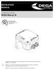
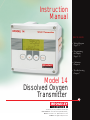
Instruction
Manual
QUICK GUIDE
• Wiring Diagram
Page 3-2
• Programming
the Display
Page 5-13
• Calibration
Chapter 6
• Troubleshooting
Chapter 7
Model 14
Dissolved Oxygen
Transmitter
19 Thomas, Irvine, California 92618 USA
Call Toll-Free: 877.246.7900 (USA & Canada)
Phone: 949.452.1112 Fax: 949.452.1114
E-Mail: [email protected]
Model 14 Oxygen Analyzer
Table of Contents
Chapter 1 : Introduction ..........................................................................................................1-1
1.1 Introduction.............................................................................................................................1-1
1.2 Principles of Operation............................................................................................................1-1
1.3 Main Characteristics ................................................................................................................1-2
1.4 Technical Specifications ...........................................................................................................1-2
1.5 Dimensions..............................................................................................................................1-4
Chapter 2 : Description of the Analyzer ...................................................................................2-1
2.1 Transmitter ..............................................................................................................................2-1
2.1.1 Presentation of the Transmitter................................................................................2-1
2.1.2 Transmitter Schematic.............................................................................................2-2
2.2 Application Fields ....................................................................................................................2-3
2.3 Standard Mounting Options .....................................................................................................2-3
Chapter 3 : Installation of the Instrument ...............................................................................3-1
3.1 Unpacking................................................................................................................................3-1
3.2 Inspection................................................................................................................................3-1
3.3 Mounting .................................................................................................................................3-1
3.4 Location...................................................................................................................................3-1
3.5 Power Connection....................................................................................................................3-1
3.6 Transmitter Start-Up.................................................................................................................3-1
3.7 Adjusting the Display Contrast..................................................................................................3-1
3.8 Electrical Connections .............................................................................................................3-2
3.9 Terminal Descriptions..............................................................................................................3-3
3.10 Changing the Programming Language ....................................................................................3-4
3.11 Changing the Power Supply Frequency...................................................................................3-5
Chapter 4 : Using the Instrument .............................................................................................4-1
4.1 Front Panel Keys ......................................................................................................................4-1
4.2 Displays 1 - 4...........................................................................................................................4-2
4.3 Description of the Function Keys..............................................................................................4-3
4.4 Icons........................................................................................................................................4-3
4.5 Enter or Modify a Value ...........................................................................................................4-4
Chapter 5 : Programming the Analyzer ....................................................................................5-1
5.1 Main Menu ..............................................................................................................................5-1
5.1.1 CALIBRATION Menu ................................................................................................5-2
5.1.2 MAINTENANCE Menu...............................................................................................5-3
5.1.3 PROGRAMMING Menu.............................................................................................5-3
5.1.3.1 MEASURE Menu.............................................................................................5-4
5.1.3.2 ALARMS Menu ...............................................................................................5-5
5.1.3.3 mA OUTPUTS Menu ......................................................................................5-8
5.1.3.4 RS485 Menu ...............................................................................................5-10
i
Model 14 Oxygen Analyzer
Table of Contents
(Continued)
Chapter 5 : Programming the Analyzer (Continued) ...............................................................5-1
5.1.4 SERVICE Menu .....................................................................................................5-11
5.1.4.1 AVERAGE Menu .....................................................................................5-12
5.1.4.2 DISPLAY Menu .....................................................................................5-13
5.1.4.3 CODE Menu ..........................................................................................5-14
5.1.4.4 SOFT VERSION Menu ............................................................................5-15
5.1.4.5 DEFAULT VAL. Menu ..............................................................................5-15
5.1.4.6 mA ADJUST Menu .................................................................................5-16
5.1.4.7 CONFIGURATION Menu.........................................................................5-16
Chapter 6 : Calibrating the Instrument ....................................................................................6-1
6.1 Calibrating the Temperature Sensor .........................................................................................6-1
6.1.1 Automatic Temperature Compensation ...................................................................6-2
6.1.2 Manual Temperature Compensation .......................................................................6-3
6.2 Calibrating the Measurement ...................................................................................................6-4
6.2.1 Slope Calibration in Air with an Electric Zero.........................................................6-4
6.2.2 Slope Calibration in Air with Chemical Zero ...........................................................6-5
6.2.3 Slope Calibration in the Process with an Electric Zero ...........................................6-6
6.2.4 Slope Calibration in the Process with Chemical Zero..............................................6-7
Chapter 7 : Start-up and Troubleshooting................................................................................7-1
7.1 Start-up....................................................................................................................................7-1
7.1.1 Probe Connections .................................................................................................7-1
7.1.2 Main Power Supply Connection ..............................................................................7-1
7.1.3 Starting the Analyzer ...............................................................................................7-1
7.2 Functional Troubleshooting .....................................................................................................7-1
7.3 Troubleshooting the Electronics...............................................................................................7-3
Chapter 8: Error Messages.......................................................................................................8-1
Appendix 1 : Pressure Conversion Table..................................................................................A-1
Appendix 2 : Temperature Conversion Table ...........................................................................A-2
Appendix 3 : Default Values .....................................................................................................A-3
ii
Model 14 Oxygen Analyzer
Chapter 1:
Introduction
1.1 Introduction
The Model 14 Dissolved Oxygen Analyzer is a singlechannel analyzer for the measurement of dissolved oxygen in fermentation vessels and bioreactors, as well as
in municipal applications.
1.2 Principle of Operation
The measurement of dissolved oxygen is based on the
well-known Clark cell principle. An oxygen-permeable
membrane isolates the electrodes from the sample,
thus eliminating the need for sample conditioning.
Other reducible or oxidizable ions do not interfere,
because they cannot pass through the gas-permeable
membrane.
ing electrode (cathode) reduces the dissolved oxygen
to hydroxyl ions :
O2 + 2H2O + 4e- = 4OHA large silver counter electrode (anode) provides the
oxidation reaction:
4Ag+ + 4Cl- = 4AgCl + 4eThe reduction of oxygen is the current limiting reaction, thus making the cell current linearly proportional
to the dissolved oxygen concentration.
Electrochemical reactions and diffusion rates are temperature-sensitive. The measuring cell, therefore, is
equipped with a temperature sensor which allows an
A constant voltage supply powers two electrodes, main- automatic temperature compensation.
taining each at a constant potential. A platinum work-
1-1
Model 14 Oxygen Analyzer
1.3 Main Characteristics
■ Range: 0 - 299.99% saturation; 0 - 29.99 ppm
■ Calibration in the air
■ Temperature compensation
■ Programmable alarm levels, outputs on relays
■ 4-20 mA, 0-20 mA analog outputs
(standard)
■ Wall- , panel- and pipe mounting
1.4 Technical Specifications
Electrical Characteristics
Power Supply
Power Consumption
Connections
Fuse
90 – 265 VAC , 50/60 Hz, Self-adjusting
25 VA
Terminal blocks
5x20 mm cartridge - T2AL - 250V ANALYSIS
Analysis
Number of Inputs
Measuring Range
Accuracy
Reproducibility
Response Time (90 %)
Ambient Temperature
Relative Humidity
1-2
1
0 – 299.99% saturation
± 1% full scale
± 0.1% of range
0 – 95% full scale, <45 seconds
-20 – 60 °C (-4 … 140°F)
10 – 90% TRANSMITTER
Model 14 Oxygen Analyzer
Transmitter
Display
Units
Calibration
Analog Outputs
Temperature Compensation
RS485 (option)
Transmitter Protection
Error Reports
Display in concentration units or % saturation
Display of the direct cell current in nA
Display of the sample temperature in °C/°F
Programming via menus
nA, ppm-mg/l, °C, °F, % saturation
Electrical zero, chemical zero, slope calibration in the
air, slope process calibration by comparison with a
laboratory measurement
2 x 0/4 - 20 mA isolated from input signal, 800 ohms
load maximum
- Measurement or temperature
- Mode : linear, bi-linear
- Accuracy : 0.1 mA Alarms - Number : 4
- Functions : alarm - system alarm - timer
- Hysteresis : 0 - 10%
- Delay : 0 - 999 seconds
- Breaking power : 250 VAC, 3A maximum
30 VDC, 0.5A maximum
Automatic in the range of 0 - 80 °C
Speed : 300 - 9600 bauds
Insulation : galvanic
Station number : 32 maximum
IP 65 and NEMA 4X
Cell current > 999 nA
Sample temperature > 80 °C
Ambient temperature > 80 °C
Slope calibration error
Zero calibration error (offset)
Electromagnetic Compatibility
Immunity Against Electromagnetic Interferences
Electromagnetic Emission
Low Voltage Standard
EN 50082-2 and EN 50082-1
EN 50081-1 and EN 50081-2
IEC61010-1 MATERIALS
Materials
Working Electrode
Counter Electrode
Membrane Holder
Membrane
Transmitter
Probe Body
NTE
Maintenanace
NANCE
Cleaning
Cathode : platinum
Anode : silver
PPS & silicone
PTFE
Epoxy coated aluminum
Stainless steel 316L MAI
Clean the instrument with a soft tissue.
DO NOT use any aggressive agent.
1-3
Model 14 Oxygen Analyzer
1.5 Dimensions
(Dimensions are in mm and inches)
144 mm 5.669"
24 mm 0.945"
1-4
Esc
28 mm 1.102"
2 Pg13
Enter
73 mm 2.874"
144 mm 5.669"
117 mm 4.606"
24 mm 0.936"
33.5 mm 1.319"
2 Pg11
Model 14 Oxygen Analyzer
Chapter 2:
Description of the Analyzer
2.1 Transmitter
2.1.1 Presentation of the Transmitter
The electronic unit amplifies the signal of the amperometric measuring cell and converts it into a direct digital
readout in ppm, mg/l or % saturation. The transmitter is comprised of the following items:
■
■
■
■
Potentiostat which maintains the working electrode potential constant
Amperometric measuring module
Analog multiplexer
Microprocessor unit
The analog multiplexer allows measurement inputs from the measuring cell, temperature sensor and internal
checkpoints. Furthermore, the microprocessor operates the relays, the RS485 interface (optional) and the analog outputs.
The unit has an internal concentration auto-ranging feature and a microprocessor-operated calibration routine.
The output of the potentiostat is monitored for possible overdriving of the potentiostat-output stage. This condition can occur when the connections to the measuring cell are due to an inoperable electrode or a defective reference electrode.
2-1
Model 14 Oxygen Analyzer
2.1.2 Transmitter Schematic:
REFERENCE
3
1
ANODE
2
U
TEMP +
9
4
TEMP -
CATHODE
5
AUX
6
7
1 : Programmable potentiostat
6 : Auxiliary input
2 : Polarization voltage amplifier
7 : Multiplexer
3 : Reversing switch for a 2 or 3 electrode
8 : A/D converter
operation.
4 : Temperature measurement circuit
5 : Measurement circuit current amplifier
2-2
9 : Microprocessor
8
Model 14 Oxygen Analyzer
2.2 Application Fields
Easy to use, install and program, this instrument is suitable for the following applications:
- Fermentation / biotech
- Municipal
2.3 Standard Mounting Options (using the red clamping bow)
The transmitter housing conforms to norm DIN 43700.
8 mm (0.315”) max.
Panel mounting
Panel cut-out: 138 mm x 138 mm (5.4” x 5.4”)
Front panel dimensions: 144 mm x 144 mm (5.7” x 5.7”)
Included hardware: 2 flat head screws, 4 mm x 18 mm long, for panels up to 6 mm thick
285 mm (11.22”) max.
80 mm (3.15")
(b)
(a)
Wall mounting
Included hardware: 2 pan head screws, 4 mm x 60 mm long for red clamping bow (a)
Additional required hardware: 2 flat head screws, 4 mm x 60 mm long (b)
Placed 3.15 “ (80 mm) on center
2-3
Model 14 Oxygen Analyzer
Vertical pipe mounting
Included hardware: 2 pan head screws,
4 mm x 60 mm long for red clamping bow
42 mm (1.653") max.
2-4
320 mm (12.598") max.
Horizontal pipe mounting
Included hardware: 2 pan head screws,
4 mm x 60 mm long for red clamping bow
Model 14 Oxygen Analyzer
Chapter 3:
Installation of the Instrument
3.4 Location
3.1 Unpacking
The analyzer should be unpacked with great care. The analyzer should be located in an accessible site.
Watch for any loose accessories.
The site should permit access for any inspection or
maintenance operation.
3.2 Inspection
3.5 Power Connection
The analyzer has been factory checked and tested prior
to shipment. It is advisable, however, to inspect all For safety reasons, it is required to observe the preparts immediately upon receipt for any damage which cautions below:
may have occurred during shipping. A damaged shipping container may indicate internal damage, which 1. The instrument should be connected to the power
may not be immediately obvious. If there is any evi- supply by means of a breaker located close to the
dence of damage, keep the shipping container and instrument and clearly identified.
refer to your local agent or to:
2. This breaker should switch off phase and neutral in
Broadley Technologies Corporation
case of electrical problems or to service the instru19 Thomas, Irvine, CA 92618 USA
ment. However, the earth ground must always be con949-452-1112
nected.
Toll Free in the US and Canada 877-246-7900
3.6 Starting the Transmitter
3.3 Mounting
Before switching on the transmitter, make sure the
site voltage corresponds to the instrument voltage
indicated on the identification plate.
CAUTION!
Mounting should be done by
qualified service personnel only.
No power should be applied until
the installation is complete.
m
3.7 Adjusting the Display Contrast
If the display contrast is not sufficient, adjust the
potentiometer P1 (blue color, see figure on page
3-2), which is located on the top left of the CPU
board (after opening the enclosure).
Before servicing the instrument,
confirm the power supply is “off”.
3-1
Model 14 Oxygen Analyzer
3.8 Electrical Connections
■ Model 14
Do not switch the instrument on until completion of the installation.
An aluminum armor plate inside the Model 14 gives a detailed description of the different terminals and their
connections:
➯ The Relays and Main Power Supply terminals represented on the right side are accessible by removing
the armor plate.
Preamp.
Supply
+
l1
S1
l2
Relays
+
S2
S3 / Sys.Alarm
RX / TX +
RX / TX
Temp +
Temp
NC.
Anode GND
Cathode GND
NC
+V
GND
-V
S4 / Timer
T 2A L
F1
PE
Mains
Amp. module
RS485
(option)
Analog
Outputs
Serial N°:
50 / 60Hz
N
L
25VA
Vac: 90...265V
Zellweger Analytics SA / F-93165 Noisy-le-Grand
Made in the E.E.C
3-2
Model 14 Oxygen Analyzer
3.9 Terminal Descriptions
+
+
1
2
RS485
(option)
Analog
Outputs
0/4 - 20 mA outputs
galvanic insulation
RX/TX+
RX/TX-
Amp module
amperometric
module
Temp+
TempNC
Anode
Cathode
NC
Amp module
Mains
Preamp
Supply
GND
GND
+V
GND
-V
PE
N
L
Temp+
TempNC
Anode
Cathode
NC
DESCRIPTION
0 - 20 mA or 4 - 20 mA (n°1) [+]
0 - 20 mA or 4 - 20 mA (n°1) [-]
0 - 20 mA or 4 - 20 mA (n°2) [-]
0 - 20 mA or 4 - 20 mA (n°2) [+]
RS485 Option
DESCRIPTION
Temperature sensor [+]
Temperature sensor [-]
Reference if using 3 electrodes
Anode
Cathode
Auxiliary
External shield
Internal shield
Not used for the oxygen measurement
Behind aluminum plate
Main power supply, 90...265 VAC 50/60 Hz
or 24 V AC/DC (special version)
DESCRIPTION
Alarm 1, simple contact
Alarm 2, simple contact
Alarm 3 or alarm system, simple contact
Alarm 4 or timer, simple contact
CONNECTION
user
user
user
user
user
user
COLOR
CONNECTION
black
temp +
blue
temp not used on the Model 14
oxygen analyzer
red
Anode
white
Cathode
N.C.
braid
armor plate
brown
GND
N.C.
Ground
CONNECTION
user
user
user
user
➯ Electrical connections should remain dry to ensure proper operation of the instrument.
Check the creeping of the cables when opening the transmitter.
➯ Shielded cables are recommended. This shielding should be connected to the earth central
shielding.
3-3
Model 14 Oxygen Analyzer
3.10 Changing the Programming Language
The default programming language is English. To change the language,
follow the procedure below (example for French):
MENU
100
CALIBRATION
MAINTENANCE
PROGRAMMING
SERVICE
% Sat
23.2°C
Disp2
O2
Select
Menu
Enter
SERVICE
DISPLAY
Enter
CONC: ppm
TEMP.: °C
PRESSURE: mmHg
LANGUAGE: GB
Select
Select
DISPLAY
CONC: ppm
TEMP.: °C
PRESSURE: mmHg
LANGUAGE: F
Select
3-4
AVERAGE
DISPLAY
CODE
SOFT ISSUE
DEFAULT VAL.
ADJUST mA
CONFIGURATION
DISPLAY
Enter
CONC: ppm
TEMP.: °C
PRESSION: mmHg
LANGUE: F
Select
Esc
(press 3 times)
Model 14 Oxygen Analyzer
3.11 Programming the Power Supply Frequency
The power supply frequency can be changed if necessary. This change occurs at the initial startup and after resetting the instrument. Follow the procedure below.
MENU
100
% Sat
23.2°C
Disp2
Enter
CALIBRATION
MAINTENANCE
PROGRAMMING
SERVICE
O2
Menu
Select
Enter
SERVICE
CONFIGURATION
FREQ: 50Hz
Enter
AVERAGE
DISPLAY
CODE
SOFT ISSUE
DEFAULT VAL.
ADJUST mA
CONFIGURATION
Select
Select
DISPLAY
DISPLAY
FREQ: 60Hz
FREQ: 60Hz
Enter
Esc
(press 3 times)
3-5
Model 14 Oxygen Analyzer
3-6
Model 14 Oxygen Analyzer
Chapter 4:
Using the Instrument
4.1 Front Panel Keys
The display may be programmed to indicate :
■ Sample concentration
■ Sample temperature
■ Diffusion current
■ Programming codes
■ Programming features
Figure 4-1 : Front Panel
4-1
Model 14 Oxygen Analyzer
4.2 Displays 1 to 4 (live displays)
100% : Dissolved Oxygen measurement
S1
S3
100
% Sat
23.2°C
S2
Disp2
O2
Menu
S1
S4
S3
100%
23.2°C
60.4 nA
S2
S1
Display of the parameters measured :
% Saturation
Temperature
Cell current
S4
Disp3
S1:
S2:
S3:
S4:
23.2°C : Temperature measurement
O2 : Application
S1...S4 : Alarm status
(invisible if alarm is inactive)
ppm >3
OK
ppm >5
OK
S3
S1...S4 : alarm status
In this case relays S1 and S3 are active
Disp4
I1: Conc
4.9 mA
I2: Conc
4.9 mA
Main
4-2
Analog output allocation and level
Numeric and bargraph indication
Model 14 Oxygen Analyzer
4.3 Description of the Function Keys
The function keys below will be highlighted at the bottom of the screen :
Modify a parameter
Select
Scrolling in a list of menus
Main
Return to the main display
Menu
Display the main menu
Disp2
Display screen 2
Disp3
Display screen 3
Disp4
Display screen 4
OK
Validate the measure during calibration
Yes
Confirm a command
-
Decrease a value
+
Increase a value
4.4 Icons
Wait for instrument to reset
Alarm system for relay S3
Timer symbol : countdown for relay S4
P
Controller symbol
4-3
Model 14 Oxygen Analyzer
4.5 Enter or Modify a Value
The highlighted digit can be modified with the key
.
Each digit can be validated by pressing ENTER. Repeat both operations for each digit.
03.89 ppm
Increase the digit value
13.89 ppm
Enter
Validate the digit value
13.89 ppm
15.89 ppm
15.89 ppm
Enter
Enter
15.89 ppm
15.39 ppm
Enter
15.39 ppm
15.37 ppm
Enter
15.37 ppm
To change the unit
15.37 ppm
WARNINGS!
Note 1 : If you do not use the keyboard for at least 10 minutes, the instrument returns to the measuring mode.
Note 2 : An access code may be required for the CALIBRATION, PROGRAMMING or SERVICE menus (see CODE menu).
It is possible to display a negative first digit “-”
It is possible to display a “.” for the other digits.
4-4
Model 14 Oxygen Analyzer
Chapter 5:
Programming the Transmitter
5.1 Main Menu
S1
S3
100
% Sat
23.2°C
S2
O2
Disp2
Menu
S4
MENU
CALIBRATION
MAINTENANCE
PROGRAMMING
SERVICE
Select
CALIBRATION
CONC. CALIB.
TEMP. CALIB.
MAINTENANCE
21.0 ppm
PARAMETERS
Select
Page 5-2
23.2°C
60 nA
Page 5-3
PROGRAMMING
MEASURE
ALARMS
mA OUTPUTS
RS485
Select
Page 5-3
SERVICE
AVERAGE
DISPLAY
CODE
SOFT ISSUE
DEFAULT VAL.
ADJUST mA
CONFIGURATION
BROADLEY J.
Select
Page 5-11
5-1
Model 14 Oxygen Analyzer
5.1.1 CALIBRATION Menus
➯ Any calibration should follow the procedure below:
1. Configure the calibration characteristics in the “PROGRAMMING” menu.
2. Perform the calibration via the “EXECUTION” menu.
m
An access code may be required if one has been programmed,
see page 5-14 for CODE Menu.
The Temp. Calib. menu will not appear when instrument is set for manual
temperature compensation.
CALIBRATION
Enter
CONC. CALIB.
TEMP. CALIB.
PARAMETERS
HISTORIC
Enter
Select
CONC. CALIB.
TEMP. CALIB.
Enter
ZERO
EXECUTION
SLOPE
PARAMETERS
DATE: 01/01/98
Select
Zero: 0.00nA
Select
S: 5.40nA/ppm
∆T: 0.0 ˚C
Parameters
5-2
DATE
mm/dd/yy
Date of the last calibration. The date programmed is not updated automatically.
S
x.xxx nA/ppm Slope value
∆T
x.x°C
Drift between the theoretical temperature (sensor curve) Th and the temperature
measured Tm :DT = Th - Tm
Model 14 Oxygen Analyzer
5.1.2 MAINTENANCE Menu
MAINTENANCE
Used for any maintenance operation in the instrument; the transmitter
continues to display the variables measured. The relay status is not
modified.
21.0 ppm
The relay status is not modified.
The analog output value depends on the configuration in the
mA OUTPUTS/SPECIAL PROG. /MAINTENANCE menu.
21.6°C
60.5 nA
5.1.3 PROGRAMMING Menu
m
An access code may be required.
See page 5-14 for CODE menu.
PROGRAMMING
MEASURE
ALARMS
mA OUTPUTS
RS485
Select
MEASURE
P: 0760.0mmHg
TEMP. COMP
SALINITY COMP
Select
Page 5-4
ALARMS
ALARMS
ALARMS
ALARMS
ALARMS
Select
Page 5-5
1
2
3
4
mA OUTPUTS
OUTPUT 1
OUTPUT 2
SPECIAL PROG.
TEST
Select
Page 5-8
RS485
N: 00
BAUD : 9600
PARITY : No
STOP BIT : 1
Select
Page 5-10
5-3
Model 14 Oxygen Analyzer
5.1.3.1 MEASURE Menu
PROGRAMMING
Enter
MEASURE
P: 0760.0 mm Hg
MEASURE
ALARMS
mA OUTPUTS
RS485
TEMP. COMP.
SALINITY COMP.
Select
Enter
Select
TEMP. COMP.
TYPE: Manual
TEMP.: 25.02˚C
Select
Temperature Compensation
TYPE
- Auto
- Manual
Choice of a temperature measurement with automatic compensation or
manual compensation
When manual temperature compensation is selected,
the TEMP.CALIB. menu is no longer accessible!
m
TEMP.
5-4
- XX.X°C
In the case of manual compensation, enter the sample temperature
Model 14 Oxygen Analyzer
5.1.3.2 ALARMS Menu
Relays S1 through S4 may be allocated to the limit, alarm system or timer functions.
PROGRAMMING
ALARMS
ALARM 1
MEASURE
ALARMS
mA OUTPUTS
RS485
Enter
ALARM 2
ALARM 3
ALARM 4
Select
Select
➯ LIMIT FUNCTION:
The alarm relays are activated when the comparison between the measured value and the programmed limits
meets the alarm function condition (up or down). The limits are programmed according to the following
programming variables:
Limit Alarm Function
AFFECT
ALARMS
AFFECT.: Conc.
LIM.: 0.001ppm
DIR.: Down
DELAY: 000s
HYST.: 00%
RELAY: NO
Select
LIM
DIR.
DELAY
HYST.
RELAY
-Conc.
- No
-°C/°F
XXXX
-Up
-Down
XXXs
XX%
-NO
-NC
Programmed for a concentration
or temperature limit or not active.
Enter a limit value
Choice of the direction
Time before the relay is executed (in seconds)
Definition of the hysteresis limit in % (10% max.). The
hysteresis operates on only one side of the limit. The
hysteresis is below the limit for the high alarm (up)
and above the limit for the low alarm (down).
Relay normally open or normally closed
5-5
Model 14 Oxygen Analyzer
➯ SYSTEM ALARM FUNCTION:
Relays S3 and S4 may be used as a fault indicater. To control the faults traced by the analyzer, connect the
specific relay to an external alarm system. The relay is activated as soon as a default appears.
In the case of a manual acknowledgment, the relay remains activated even if the default disappears.
Press ENTER to deactivate the relay and the error message. In the case of an automatic acknowledgment,
the relay and the error message are deactivated when the default disappears.
System Alarm
ALARM 3
MODE
-No
-Limit
-System
The alarm S3 may be programmed to be a limit
function (see paragraph above) or an alarm
system function
ACCEPT
-Auto
-Manu.
In the case of an alarm system, choose between
a manual (key ENTER) or an automatic
acknowledgment
RELAY
-NO
-NC
Alarm S3 can be normally open or normally closed
MODE: System
ACCEPT.: Auto
RELAY: NC
Select
5-6
Model 14 Oxygen Analyzer
➯ TIMER FUNCTION:
Relays S3 and S4 may be programmed to a timer function.
Timer Function
ALARM 4
MODE: Timer
INTERV: 1440mm
IMPUL. Nb.: 5
Ton: 005s
Toff: 003s
TmA: 05mn
MODE
-No
-Limit
-Timer
The Alarm 4 may be a limit (see parameters
above) or a timer function
INTERV
XXXXmn
Interval between 2 active cycles (in minutes)
IMPUL.Nb:
X
Number of pulses during an active cycle
Ton
XXXs
Adjustment of the relay active time (in seconds)
for each pulse
Toff
XXXs
Adjustment of the relay inactive time (in seconds)
for each pulse
TmA
XXmn
Hold time for the analog outputs after each cycle
➯ The analog output status depends on the
configuration of the menu mA OUTPUTS/
SPECIAL PROG./TIMER
Select
The measurement cycle lasts 4 seconds.
Example of a timer operating cycle :
Relay S4
pulse number
Closed
Open
Time
TmA
Ton Toff
Interval
5-7
Model 14 Oxygen Analyzer
5.1.3.3 mA OUTPUTS Menu
The analog output signals allow the transmission of the measurements from the analyzer to any external control
system.
It is highly recommended to use shielded cables for the output signals. This shielding should be connected to
the earth terminal on the armor plate.
PROGRAMMING
MEASURE
ALARMS
mA OUTPUTS
RS485
mA OUTPUTS
Enter
OUTPUT 1
OUTPUT 2
SPECIAL PROG.
TEST
Enter
Enter
Select
Select
SPECIAL PROG.
OUTPUTS 1/2
MAINTENANCE
CALIBRATION
SYST. ALARM
TIMER
Select
Enter
AFFECT.:
Conc.
TYPE: 4-20
MODE: Lin
LOW: 001 nA
UP: 100.0 nA
Select
Enter
TEST
VALUE: 00
SPECIAL PROG.
MODE:
Preset
VALUE: 00
Select
5-8
mA
mA
Model 14 Oxygen Analyzer
Output 1/2
AFFECT
TYPE
MODE
LOWER
MIDD.
UPPER
- Conc.
- nA
- ˚C/˚F
- 0/20
- 4/20
- Lin
- Dual
XXXX
XXXX
XXXX
To set the choice of analog output to the
concentration or temperature measurement
Choice of the analog output type
Choice between a linear or dual range (see drawing below)
Bottom scale value
Mid-scale value (only in dual mode)
Top of the scale value SPECIAL PROG.
Special Prog.
MODE
- last
- preset
- live
VALUE
XX
Characteristics of the analog output during calibration,
alarm system, maintenance or timer active cycles. Display
and output will be last stored value, a preset value, or a live
measurement
Preset value ( 0 to 21 mA) TEST
Test the analog outputs in 1 mA increments (0 to 21 mA)
Test
UPPER
MIDDLE
LOWER
(mA)
20 20
16
15
12
10
8
5
4
0
0
Dual
Linear
10
20
30
40
50
60
70
80
90
100 (%)
5-9
Model 14 Oxygen Analyzer
5.1.3.4 RS485 Menu (optional)
If the RS485 optional board is installed, program the parameters of the menu below.
The optional RS485 board enables a connection between the analyzer and a digital communication system. The
communication protocol is JBUS/MODBUS. Call Broadley Technologies for more information.
PROGRAMMING
MEASURE
ALARMS
mA OUTPUTS
RS485
Select
RS485
Enter
N: 00
BAUD: 9600
PARITY: No
STOP BIT: 1
Select
RS485
N°
BAUD
PARITY
BIT STOP
5-10
XX
- 300
- 600
- 1200
- 2400
- 4800
- 9600
- No
- Odd
- Even
-1
-2
Enter number (0 – 32)
Transmission speed in baud
Without parity bit
With odd parity bit
With even parity bit
1 bit stop
2 bit stop
Model 14 Oxygen Analyzer
5.1.4 SERVICE Menu
CALIBRATION
AVERAGE
DISPLAY
CODE
SOFT ISSUE
DEFAULT VAL.
ADJUST mA
CONFIGURATION
BROADLEY J.
Select
AVERAGE
DEFAULT VAL.
AVERAGE: 9
Loading
TEST
SOFT ISSUE
m
Default
Values?
Select
Yes
Model 1400
DO 1.00
DISPLAY
ADJUST mA
CONC: ppm
TEMP: ˚C
PRESSURE: mmHg
LANGUAGE: GB
OUTPUT 1
Select
Select
CODE
CALIF.
: 0000
PROG.
: 0000
SERVICE : 0000
Select
OUTPUT 2
CONFIGURATION
FREQ: 60Hz
Select
5-11
Model 14 Oxygen Analyzer
5.1.4.1 AVERAGE Menu
m
An access code may be required.
See page 5-14 for CODE menu.
Program a moving average on the concentration measurement.
The measurement cycle lasts 4 seconds.
SERVICE
Enter
AVERAGE
DISPLAY
CODE
SOFT ISSUE
DEFAULT VAL.
ADJUST mA
CONFIGURATION
BROADLEY J.
Select
AVERAGE
AVERAGE: 9
TEST
TEST
Enter
Average
3.46 ppm
Real
3.49 ppm
Select
Average
AVERAGE
Test
5-12
X
Define the number of measurements to calculate the average (1-10)
Display the difference between a measurement obtained with and
without averaging
Model 14 Oxygen Analyzer
5.1.4.2 DISPLAY Menu
DISPLAY
SERVICE
AVERAGE
DISPLAY
CODE
SOFT ISSUE
DEFAULT VAL.
ADJUST mA
CONFIGURATION
BROADLEY J.
Enter
CONC: ppm
TEMP: ˚C
PRESSURE: mmHg
LANGUAGE: GB
Select
Select
Display
CONC
TEMP.
PRESSURE
- % sat
- ppm
- mg/l
- °C
- °F
- mmHg
- mbar
- inHg
LANGUAGE
-F
- GB
-D
- Sp
-I
Choice of measurement units
Choice of temperature units
Choice of atmospheric pressure units
Choice of languages :
- French
- English
- German
- Spanish
- Italian
5-13
Model 14 Oxygen Analyzer
5.1.4.3 CODE Menu
Protection codes may be programmed for access to the PROGRAMMING, CALIBRATION, and SERVICE menus.
This code is deactivated by entering 0000.
CODE
SERVICE
AVERAGE
DISPLAY
CODE
SOFT ISSUE
DEFAULT VAL.
ADJUST mA
CONFIGURATION
BROADLEY J.
CALIB.
Enter
PROG.
: 0000
: 0000
SERVICE: 0000
Select
Select
Code
CALIB.
PROG.
SERVICE
XXXX
XXXX
XXXX
Access code to the “CALIBRATION “ menu
Access code to the “PROGRAMMING” menu
Access code to the “SERVICE” menu
To override the access code, press ESC and ENTER simultaneously to enter the menu
selected.
5-14
Model 14 Oxygen Analyzer
5.1.4.4 SOFT ISSUE Menu
This menu displays the software version installed in the instrument.
SERVICE
AVERAGE
DISPLAY
CODE
SOFT ISSUE
DEFAULT VAL.
ADJUST mA
CONFIGURATION
BROADLEY J.
SOFT ISSUE
Enter
Model 1400
DO 1.00
Select
5.1.4.5 DEFAULT Menu
SERVICE
AVERAGE
DISPLAY
CODE
SOFT ISSUE
DEFAULT VAL.
ADJUST mA
CONFIGURATION
BROADLEY J.
Select
m
DEFAULT VAL.
Loading
Enter
m
Default
Values?
Yes
Pressing YES will load the default values. The current programmed values,
historic values and calibration parameters will be lost.
5-15
Model 14 Oxygen Analyzer
5.1.4.6 mA ADJUST Menu
The analog output signals are factory-adjusted (upper limit: 20mA). However, if the upper limit of one of the
outputs, drifts, the span value can be adjusted with the mA ADJUST menu. Connect an ampere meter in series
to the analog output terminals. Adjust the value until the ampere meter displays 20mA.
Note: The value displayed does not correspond to an actual mA value.
AVERAGE
DISPLAY
CODE
SOFT ISSUE
DEFAULT VAL.
ADJUST mA
CONFIGURATION
BROADLEY J.
ADJUST mA
ADJUST mA
SERVICE
OUTPUT 1
VALUE:
OUTPUT 2
0000
Enter
Enter
Select
Select
-
+
5.1.4.7 CONFIGURATION Menu
The operating frequency must be programmed to match the power supply. When the frequency is changed, the
instrument is automatically reset.
SERVICE
AVERAGE
DISPLAY
CODE
SOFT ISSUE
DEFAULT VAL.
ADJUST mA
CONFIGURATION
BROADLEY J.
Select
CONFIGURATION
FREQ:
60Hz
CONFIGURATION
FREQ:
Enter
50Hz
Select
Enter
Please
wait …
Disp2
Menu
Disp2
Start up …
Menu
Disp2
5-16
Menu
Model 14 Oxygen Analyzer
Chapter 6:
Calibrating the Instrument
NOTE
See Chapter 5 for programming commands.
REMARK
Any result (calibration or measurement) is always brought back to the
reference temperature (25˚C, 77˚F). If the sample temperature is different
from the reference temperature, manual or automatic temperature
compensation must be used.
6.1. Calibrating the Temperature Sensor
The temperature sensor is located in the dissolved oxygen measurement probe. It is pre-set by the factory, but needs
to be calibrated in the sample, on-site. The temperature sensor must be calibrated before calibrating the sensor’s
slope and zero.
6-1
Model 14 Oxygen Analyzer
6.1.1. Automatic Temperature Compensation
The sensor continuously measures the sample temperature. The concentration values are automatically
calculated using the algorithms programmed in the transmitter.
1. Programming
PROGRAMMING
Enter
MEASURE
ALARMS
mA OUTPUTS
RS485
MEASURE
Choose automatic temperature compensation. ?
P: 0760.0 mm Hg
TEMP. COMP
SALINITY COMP.
Select
Enter
Select
TEMP. COMP.
TYPE:
Auto.
Select
2. Execution
TEMP. CALIB.
The execution is begun in the CALIBRATION
menu.
EXECUTION
Select
Enter
21.2
21.2
˚C
6.87ppm
˚C
CAL
21.2 ˚C
CAL
OK
Press OK when the
measurement is stable
Can change the value
TEMP. CALIB.
∆T: 0.0 ˚C
Enter
ENTER : ok
ESC : cancel
6-2
Enter the sample temperature value in °C.
Press OK to adjust the temperature displayed
to the actual value of the sample temperature
measured with a precise thermometer.
The gap between the calibration and the
theoretical response curve of the sensor is
given for information.
Model 14 Oxygen Analyzer
6.1.2. Manual Temperature Compensation
Manual temperature compensation should be used only when the sample temperature is constant.
1. Programming
PROGRAMMING
Enter
Select manual temperature compensation.
TEMP. COMP
MEASURE
ALARMS
mA OUTPUTS
RS485
Select
MEASURE
Enter
Select
TEMP. COMP.
TYPE: Manual
Select
Enter
TEMP. COMP.
TYPE: Manual
Enter the sample temperature.
TEMP.: 25.0˚
Select
2. Execution
Not applicable when manual temperature
compensation is selected.
6-3
Model 14 Oxygen Analyzer
6.2. Measurement Calibration
The slope calibration can be done in air or water. The zero can be set with an electronic zero or a chemical
zero. A chemical zero uses Nitrogen gas or oxygen-free solution.
6.2.1. Slope Calibration in Air with an Electronic Zero
Temperature compensation must be set to “auto.”
1. Programming
ZERO :
Select an electrical zero. The electrical zero is
carried out automatically by the transmitter at
regular intervals.
Select slope in air.
CALIBRATION
Enter
CONC. CALIB.
CONC. CALIB.
TEMP. CALIB.
ZERO
PARAMETERS
SLOPE
Enter
Enter
Select
Select
ZERO CALIB.
SLOPE CALIB.
PROGRAMMING
PROGRAMMING
EXECUTION
Enter
Select
Select
ZERO CALIB.
Enter
SLOPE CALIB.
TYPE: ElectAuto.
TYPE:
Air
SLOPE :
Enter the atmospheric pressure in mmHg
Enter the ambient temperature in °C ? EXECUTION
PO: 760.0 mmHg
Tamb.: 20.0 ˚C
Select
Select
2. Execution
SLOPE : Remove the probe from the sample and
press ENTER. The probe should be positioned
with the membrane downward.
SLOPE CALIB.
PROGRAMMING
EXECUTION
Enter
Select
21.2
ppm
SLOPE CALIB.
DATE: 01/01/98
S:3nA/ppm
The flashing “CAL” message indicates that the
instrument is in calibration mode. Wait for the
current to stabilize (approximately 1-2 min.)
and press OK to validate the calibration. The
oxygen concentration value flashes for 3 seconds.
25.0 ˚C
60.0nA
CAL
CAL
OK
Enter the date of
the calibration
6-4
The analyzer displays the date of the last calibration and the new slope calculated. The date can
be modify. Put the electrode back into service.
Model 14 Oxygen Analyzer
6.2.2. Slope Calibration in Air with a Chemical Zero
1. Programming
CALIBRATION
CONC. CALIB.
Enter
ZERO :
Select a chemical zero
Select slope in air
CONC. CALIB.
TEMP. CALIB.
ZERO
PARAMETERS
SLOPE
Select
Enter
Enter
Select
ZERO CALIB.
SLOPE CALIB.
PROGRAMMING
PROGRAMMING
EXECUTION
Enter
Select
Select
ZERO CALIB.
Enter
SLOPE CALIB.
TYPE: Chemical
TYPE:
Air
SLOPE :
Enter the atmospheric pressure in mmHg
Enter the value of the ambient temperature
PO: 760.0 mmHg
Tamb.: 20.0 ˚C
Select
Select
2. Execution
ZERO :
Place the sensor in 99.999% Nitrogen gas.
ZERO CALIB.
PROGRAMMING
EXECUTION
Select
Enter
21.2
0
ppm
25.0 ˚C
CAL
OK
ppm
25.0 ˚C
Press ENTER, the “CAL” message flashes and
indicates the instrument is in calibration mode.
Wait for the current to stabilize
(approximately 1-2 min.) and press OK
to validate the calibration. The oxygen
concentration value flashes for 3 seconds.
The instrument displays zero.
CAL
OK
6-5
Model 14 Oxygen Analyzer
6.2.3. Slope Calibration in Process with an Electronic Zero
1. Programming
CALIBRATION
Enter
CONC. CALIB.
ZERO :
Select the electrical zero. The electrical zero
is carried out automatically by the transmitter
at a regular frequency.
Select process slope.
CONC. CALIB.
TEMP. CALIB.
ZERO
PARAMETERS
SLOPE
Enter
Enter
Select
Select
ZERO CALIB.
PROGRAMMING
SLOPE CALIB.
PROGRAMMING
EXECUTION
Enter
Select
Select
ZERO CALIB.
TYPE: ElectAuto.
Select
Enter
SLOPE CALIB.
TYPE:
Process
Select
2. Execution
SLOPE CALIB.
PROGRAMMING
EXECUTION
Enter
Select
21.2
ppm
SLOPE CALIB.
DATE: 01/01/98
S:3nA/ppm
25.0 ˚C
60.0nA
CAL
CAL
OK
Enter the date of
the calibration
6-6
SLOPE :
The “CAL” message flashes and indicates the
instrument is in calibration mode. Wait for
the current to stabilize and press OK.
It is possible to adjust the concentration value
digit by digit with the function key to the desired
value.
The analyzer displays the date of the last calibration and the new slope calculated. This date can
be modified.
Model 14 Oxygen Analyzer
6.2.4. Slope Calibration in Process with a Chemical Zero
1. Programming
CALIBRATION
Enter
CONC. CALIB.
CONC. CALIB.
TEMP. CALIB.
ZERO :
Select chemical zero.
Select slope process.
ZERO
PARAMETERS
SLOPE
Enter
Enter
Select
Select
ZERO CALIB.
SLOPE CALIB.
PROGRAMMING
PROGRAMMING
EXECUTION
Enter
Select
Select
ZERO CALIB.
Enter
SLOPE CALIB.
TYPE: ElectAuto.
Select
TYPE:
Process
Select
2. Execution
ZERO :
Place the sensor in 99.999% Nitrogen gas.
ZERO CALIB.
PROGRAMMING
EXECUTION
Select
Enter
21.2
0
ppm
25.0 ˚C
5.693nA
Press ENTER, the “CAL” message flashes and
indicates the instrument is in calibration mode.
Wait for the current to stabilize (approximately
10 min.) and press OK to validate the calibration.
The oxygen concentration value flashes for 3
seconds.
The instrument will display zero.
ppm
25.0 ˚C
CAL
5.693nA
OK
CAL
OK
SLOPE CALIB.
PROGRAMMING
EXECUTION
Enter
Select
21.2
ppm
SLOPE CALIB.
DATE: 01/01/98
S:3nA/ppm
25.0 ˚C
60.0nA
CAL
SLOPE :
The flashing “CAL” message indicates that the
instrument is in calibration mode. Wait for the
current to stabilize (approximately 10 min.)
and press OK to validate the calibration. The
oxygen concentration value flashes for 3 seconds.
CAL
OK
The analyzer displays the date of the last calibration
and the new slope calculated. This date can be
modified.
Enter the date of
the calibration
6-7
Model 14 Oxygen Analyzer
6-8
Model 14 Oxygen Analyzer
Chapter 7:
Start-up and Troubleshooting
7.1 Start-up
7.1.1 Probe Connection
PROBLEM: No significant current increase
when the probe is in the air during
calibration
See page 3-3 for the terminal connection.
Causes and solutions:
7.1.2 Main Power Supply Connection
A) The membrane has been torn.
➯ Change the membrane.
Remove aluminum plate inside the Model 14. Power
should be connected to the “Mains” terminal indicated B) Cable or connections have been damaged.
on the plate. See Page 3-3 for terminal connections.
➯ Check the connection to the transmitter. If
the connection is correct check the connections
7.1.3 Starting the Analyzer
of the probe connector.
When switched on, the analyzer performs an automatic
test of its electronics and displays a first value. Wait
until the measurement has stabilized (max. 30 min).
Do not calibrate the analyzer before the temperature
and the concentration are stable. (See Chapter 6.)
PROBLEM: Significant instability in
measuring mode
Causes and solutions:
Note 1: Never shake the probe during a calibration, it
may provoke an introduction of oxygen in the elec- A) There is humidity or water in the probe connector.
trolyte and temporarily increase the cell current.
➯ Dry the connector. Check connections.
7.2 Functional Troubleshooting
PROBLEM: Excessive time for stabilization
or no stabilization during air calibration.
Causes and solutions:
B) Incorrect connection.
➯ Check the connections of the transmitter to
the probe.
C) Electromagnetic interferences close to the probe
or transmitter cable.
➯ Find a better place for the cable and check
the EMC level.
A) There is an electrolyte leak (through the membrane). The current is too high because of an excessive penetration of oxygen.
➯ Change the membrane.
B) The electrolyte is contaminated.
➯ Change the electrolyte.
7-1
Model 14 Oxygen Analyzer
PROBLEM: Inaccurate readings
Other problems
Causes and solutions:
Causes and solutions:
A) The membrane permeability has changed (coating).
➯ Calibrate the analyzer and check if the
concentration is back to normal.
A) The probe current is zero.
➯ There is no electrolyte in the probe (leak).
There may be a short-circuit in the connection.
B) Electrolyte contamination.
➯ Inspect probe components. Change the
electrolyte.
B) The probe current is negative.
➯ Connection problem to the anode circuit
(loose contact).
➯ Deposits on the anode.
C) Leak of electrolyte.
➯ Inspect probe components. Change the
electrolyte.
D) Error during calibration or incorrect calibration.
➯ Calibrate again to check the parameters.
If the error is confirmed, check the calibration
current (too high, too low or unstable) and the
concentration in the air. Refer to the problems
described above.
E) The temperature calibration has not been
performed.
➯ Check the temperature given by the transmitter and calibrate it (see page 6-2). If
manual compensation has been selected,
confirm the value is correct.
F) The sample temperature or pressure is out of the
specifications.
➯ Change the probe location or modify the
sample so that it meets the specifications.
7-2
C) The sample temperature corresponds to the specifications, but there is an error on the temperature.
➯ There may be a short-circuit on the
temperature connection.
Model 14 Oxygen Analyzer
7.3 Troubleshooting the Electronics
WARNING!
Never attempt to service before disconnecting the instrument
from the main power line.
MALFUNCTION
POSSIBLE CAUSE
REMEDIES
No indication
No power; instrument is not
connected correctly
Check for power, then check
if connected properly
Defective fuse
Check fuse
Instrument’s power supply set for
wrong line voltage
Check jumpers on power supply board for
correct voltage settings
Ribbon cable connecting power with
CPU board not properly plugged in
Verify that the ribbon plugs are
connected properly
Connection between CPU board and
measurement module loose
Check plug connections
Short circuit in power supply board
Visually check power supply board for shorts
Hardware is defective
Call the Service Technician
Malfunctioning CPU board or
processor
Using the Instruction Manual, program the
instrument to load the default values
CPU hardware
RESET the instrument by temporarily
interrupting the power (5-10 seconds)
LCD displays undefined
characters
Call the Service Technician
Keyboard does not
operate; all keys are
inactive
CPU malfunctioning, external
interferences
If there is no response, RESET the
instrument by temporarily interrupting the
power (5-10 seconds). Check each key
again. If there is no change, call the
Service Technician.
Measurement is not
correct
Instrument was programmed
incorrectly
Recheck programmed parameters. Do they
agree with the probe’s characteristics?
System, including probe, not
calibrated correctly
Calibrate the whole system
(with probe connected)
Probe connected wrong
Recheck all probe connections
Probe malfunctioning, possibly
incompatible with the application
Visually check the condition of the probe.
Is the application within the probe’s
specifications?
CPU board is defective
If error persists, call the Service Technician
Measurement is not stable Faulty probe
Probe connected wrong
Check the condition of the probe. Is it
contaminated?
Verify the probe is connected properly
7-3
Model 14 Oxygen Analyzer
MALFUNCTION
Temperature measurement
is not correct
Display reading static;
cannot be changed in
any way
POSSIBLE CAUSE
REMEDIES
Interferences
Are there any sources of potential
interference, chemical, external,
temperature, pressure, etc.?
Cable shield is not connected
Check and connect
Defective CPU board
If problem persists, call the Service Technician
Probe connected wrong
Check probe connection
Temperature not calibrated
Calibrate for temperature. Also check the
T.C. for correct resistance (ohmmeter)
CPU board is defective
If problem persists, call the Service Technician
CPU board is malfunctioning and/or
some other transmitter hardware is
defective
Check probe connection
Initiate a software RESET
If Steps 1-3 do not remedy the problem,
make a cold start (RESET): interrupt the
power for 5-10 seconds
Reprogram the instrument
If problem persists, call the Service Technician
Relays not energized
Instrument was programmed
incorrectly
Check whether the correct relay parameters
and set points have been programmed
Hardware is defective
Check that the programmed set points are
compatible with the programmed measuring
range
Check the relay characteristics for proper
functioning using an ohmmeter
If problem persists, contact the Service
Technician
Wrong output current,
output current remains
locked at 0 or 20 mA
Instrument was incorrectly
programmed
Check the programmed output-current
parameters
Connection of the Model 14 with
peripherals (recorder, etc.) are faulty,
loose or defective
Check the cables
Hardware is defective
Compare the measured value with the
output-current range
If problem persists, call the Service Technician
Polarization voltage
incorrect
Wrong configuration (3 electrode
mode)
Wrong programming
Check programmed parameters
7-4
Check that the switches under the
amperometric board are correctly positioned
(“on”)
Model 14 Oxygen Analyzer
Chapter 8: Error Messages
During failure, the measurement is replaced by dashes “ - - -.”
Error Message
Description
Error messages during a measurement
- - CONCENTRATION
TOO HIGH
- - STAND-BY
1.99 ppm
The concentration value exceeds the limits. Check
the current value and the calibration parameters.
Electrode protection
If the measuring range displays “concentration too
high” for more than 2 minutes, the error message
“STAND-BY” appears. From this moment on, the
electrode polarization voltage is switched off for
10 minutes before the voltage is switched on
again.
In STAND-BY the user may switch the
voltage on at any time by pressing ENTER.
The concentration value exceeds the limits. Check
the current value and the calibration parameters.
The sample temperature exceeds the limits. Check
the cable polarity. Check for a short-circuit or an
open circuit.
The current value exceeds the limits. Check the
electrode (electrolyte and membrane).
8-1
Model 14 Oxygen Analyzer
The current value exceeds the limits. Confirm
there is no short-circuit in the measuring line.
Check the polarization voltage.
Error messages during calibration
21.6
˚C
∆T
OUT OF LIMITS
8-2
The temperature difference between the calibration temperature and the sensor’s theoretical
exceeds the limit programmed.
Limits : ± 20°C
Model 14 Oxygen Analyzer
Appendix 1:
Pressure Conversion Table
hPa or mbars
mm Hg
psi
inches Hg
690
mm H2O
9503.60
13.34
27.16
inches H2O
374.16
920.00
925.00
693.8
9555.25
13.42
27.31
376.19
930.00
697.5
9606.90
13.49
27.46
378.22
935.00
701.3
9658.55
13.56
27.61
380.26
940.00
705
9710.20
13.63
27.76
382.29
945.00
708.8
9761.85
13.71
27.90
384.32
950.00
712.5
9813.50
13.78
28.05
386.36
955.00
716.3
9865.15
13.85
28.20
388.39
960.00
720
9916.80
13.92
28.35
390.43
965.00
723.8
9968.45
14.00
28.50
392.46
970.00
727.5
10020.10
14.07
28.64
394.49
975.00
731.3
10071.75
11.14
28.79
396.53
980.00
735
10123.40
14.21
28.93
398.56
985.00
738.8
10175.05
14.29
29.08
400.59
990.00
742.5
10226.70
14.36
29.23
402.63
995.00
746.3
10278.35
14.43
29.38
404.66
1000.00
750
10330.00
14.50
29.53
406.69
1005.00
753.8
10381.65
14.58
29.68
408.73
1010.00
757.5
10433.30
14.65
29.82
410.76
1015.00
761.3
10484.95
14.72
29.97
412.79
1020.00
765
10536.60
14.79
30.12
414.83
1025.00
768.8
10588.25
14.87
30.27
416.86
1030.00
772.5
10639.90
14.94
30.42
418.89
A-1
Model 14 Oxygen Analyzer
Appendix 2:
Temperature Conversion Table
• Conversion from ˚C into ˚F :
• Conversion from ˚C into ˚K :
A-2
˚F = 1.8 * ˚C + 32
˚K = ˚C + 273.15
˚C
˚F
˚K
˚C
˚F
˚K
0
32
273.15
23
73.4
296.15
1
33.8
274.15
24
75.2
297.15
2
35.6
275.15
25
77
298.15
3
37.4
276.15
26
78.8
299.15
4
39.2
277.15
27
80.6
300.15
5
41
278.15
28
82.4
301.15
6
42.8
279.15
29
84.2
302.15
7
44.6
280.15
30
86
303.15
8
46.4
281.15
31
87.8
304.15
9
48.2
282.15
32
89.6
305.15
10
50
283.15
33
91.4
306.15
11
51.8
284.15
34
93.2
307.15
12
53.6
285.15
35
95
308.15
13
55.4
286.15
36
96.8
309.15
14
57.2
287.15
37
98.6
310.15
15
59
288.15
38
100.4
311.15
16
60.8
289.15
39
102.2
312.15
17
62.6
290.15
40
104
313.15
18
64.4
291.15
41
105.8
314.15
19
66.2
292.15
42
107.6
315.15
20
68
293.15
43
109.4
316.15
21
69.8
294.15
44
111.2
317.15
22
71.6
295.15
45
113
318.15
Model 14 Oxygen Analyzer
Appendix 3: Default Values
Calibration
CONC. CALIB.
ZERO CALIB.
Type : Elec. Auto
SLOPE
Type : Air
PO: 0760.0 mm Hg
PARAMETERS
DATE :01/01/98
ZERO: 0.00 nA
S: 3.000 nA/ppm
∆T: 0.0˚C
Programming
MEASURE
TEMP. COMP.
TYPE : Auto
ALARMS S1/S2/S4
AFFECT. : Conc.
DIR. : Down
LIMIT: 0.000 ppb
DELAY : 000 s
HYST. : 00%
RELAY : NO
OUTPUT 1
AFFECT. : Conc.
TYPE : 4-20
MODE : Lin.
LOW : 0.000 ppb
UP : 01.00 ppm
MAINTENANCE
MODE : Last
SYST. ALARM
MODE : Last
ALARMS
ALARM S3
AFFECT. : System
ACQUIT : Auto
RELAY : NC
mA OUTPUTS
OUTPUT 2
AFFECT. : Conc.
TYPE : 4-20
MODE : Lin.
LOW : 0.000 ppb
UP : 01.00 ppm
SPECIAL PROG.
CALIBRATION
MODE : Last
TIMER
MODE : Last
RS485
No : 00
BAUD : 9600
PARITY : No
STOP BIT : 1 SERVICE
A-3
Model 14 Oxygen Analyzer
Service
AVERAGE
AVERAGE : 1
DISPLAY
DISPLAY
CONC. : ppb/ppm
TEMP. : °C
PRESSURE : mmHg
LANGUAGE : GB
CODE
CODE
CALIB. : 0000
PROG. : 0000
SERVICE : 0000
CONFIGURATION
CONFIGURATION
FREQ. : 60 Hz
A-4
Model 14 Oxygen Analyzer
Broadley Technologies Corporation
19 Thomas
Irvine, California 92618
USA
Corporate Headquarters:
Toll-Free: 877.246.7900
Tel: 949.452.1112 Fax: 949.452.1114
E-Mail: [email protected]
Copyright © 2000 Broadley Technologies Corporation
All Rights Reserved
A-5