1
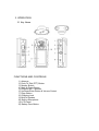
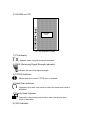
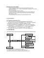
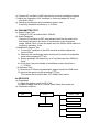
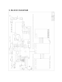
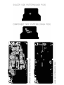
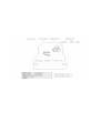
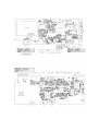
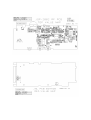
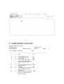
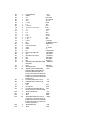
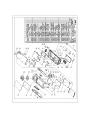
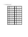
Albrecht GP 1
SERVICE MANUAL
GPS + PMR
PORTABLE
HANDHELD
RADIO
24. 04. 2002
ALAN Electronics GmbH
CONTENT
1. GPS(Global Positioning System)
2. PMR(Private Mobile Radio)
1. GENERAL
1.1 General
1.2 Characteristic
1.3 Composition
2. SPECIFICATION
2.1 General Specification
2.2 Electrical Specification
3. OPERATION
3.1 Key Name
3.2 ICONS on LCD
3.3 Key Functions
3.4 Setting and Operation
4. ADJUSTMENT
4.1 Frequency synthesizer
4.2 Transmitter
4.3 Transmitter Test
4.4 Receiver
4.5 Receiver Test
4.6 Symptoms, check point & Correction
5. DESCRIPTION OF RADIO CIRCUIT
5.1 Frequency Synthesizer
5.2 Receiver
5.3 Transmitter
3. BLOCK DIAGRAM
4. SCHEMATIC
5. COMPONENT PARTLIST
6. ASSEMBLY DRAWING
7. CHANNEL DATA
1. GPS(Global Positioning System)
1.1 PRODUCTOR : JRC
1.2 MODEL No : ALBRECHT GP 1
1.3 GPS ENGINE SPEC (ATTACH FILE)
2. PMR(Private Mobile Radio)
1. GENERAL
1.1 GENERAL
This equipment, ALBRECHT GP 1 is called 2 way portable handheld radios.
The frequency range is 446.00625~446.09375MHz UHF operating
Channels for international 2 way portable radios.
1.2 CHARACTERISTIC
a) All active device in this radio is composed of semiconductor
and high density IC.
b) To design this radio in compact and weight approximately 273g
including battery.
C) CPU of this equipment is TMP91CY22F from TOSHIBA.
d) It’s power can operate by use of Alcaline 4 cell(1.5V AA)
battery.
1.3 COMPOSITION
This radio is composed of following.
a) Transmitter(W/Antenna)
b) Belt clip
2. SPECIFICATION
2.1 GENERAL SPECIFICATIONS
a) Frequency Range : 446.00625 ~ 446.09375MHz
b) Output Impedance : 50 Ohms unbalanced
c) Modulation Type : 8K0F3E
d) Communication Mode : Half duplex
e) Channel Capacity : 8 Channel
f) Channel Spacing : 12.5 KHz
g) Power : 6.0V(alkaline)
h) Battery Life
GPS ON :
ALCA 2000mAh > 9hours(Tx 5%, Rx 5%, Stand-by 90%)
GPS OFF:
ALCA 2000mAh > 16hours(Tx 5%, Rx 5%, Stand-by 90%)
i) Operating Temperature : -20 ~ +55 °C
j) Dimension : 221.7(H)x 62.8(W)x 40.3(D)mm
k) Weight : 280g(with Battery)
2.2 ELECTRICAL SPECIFICATION
a) TRANSMITTER
1) Output Power : Max. 500mW
2) Frequency Stability : +/- 3ppm (0°C~ +30°C)
+/- 5ppm (-20°C~+55°C)
3) Modulation Method : FM
4) Oscillation Method : PLL SYNTHESIZER
5) Max. Frequency Deviation : < +/- 2.5KHz (with Tone)
6) Cooling Method : air-cooling Method
7) Spurious Emission : < -36dBm/-30dBm
8) FM Hum/Noise : > -40dB(1kHz 60% Modulation, W/CCITT)
9) Distortion : < 5% (1kHz 60% modulation)
10) Tx Audio Response : 6dB /OCT +/-3dB PRE-EMPHASIS (300Hz~2.5kHz)
b) RECEIVER
1) Receive Method : Double Super Heterodyne
2) Receive Sensitivity : < 0.28uV(20dB SINAD W/CCITT)
3) Squelch Sensitivity : 6~8dB(20dB SINAD)
4) Bandwidth : > 3kHz(6dB ATT point)
5) Selectivity : < -60dB(12.5kHz)
6) Local Frequency Stability : +/-5ppm(-20°C ~ 60°C)
7) Spurious Response : > 40dB
8) Audio output : 200mW(Internal 8Ohms load THD 10%) EXT 60mW
9) Distortion : < 5% (1kHz 60% Modulation)
10) RX Audio Response : 6dB/OCT +/-3dB DE-EMPHASIS(300Hz~2.5kHz)
11) S/N Ratio : < 40dB(1kHz 60% Modulation W/CCITT)
12) IF : 1’st IF = 21.7MHz
2’nd IF = 450kHz
13) Local Frequency : 1’st Local Frequency = fc – 21.7MHz
2’nd Local Frequency = 21.25MHz
3. OPERATION
3.1 Key Name
FUNCTIONS AND CONTROLS
1) Antenna
2) Push-To-Talk (PTT) Button
3) Monitor Button
4) Mark & Power Button
5) External MIC / Speaker
6) Up/Down/Enter Button & Volume Control
7) Page Button
8) Charging Jack
9) Built-in Speaker
10) Built-in Microphone
11) LCD Panel
12) Battery Door Button
3.2 ICONS on LCD
132 * 64
Dots
132 * 64 dots with ICONS
1) TX Indicator
Appears when a signal is being transmitted.
2) RSSI (Receiving Signal Strength Indicator)
Indicates the receiving signal strength
3) CTCSS Indicator
Blinks when the correct CTCSS tone is entered.
4) Seek Scan Indicator
Appears in the seek scan mode or when the seek scan mode is
activated.
5) Priority Scan Indicator
Appears in the priority scan mode or when the priority scan
mode is activated.
6) VOX Indicator
Blinks in VOX selection mode or appears when VOX is activated.
7) Key Lock Indicator
Blinks in auto lock selection mode or when the key lock is
activated.
8) GMRS Indicator
Appears GMRS is activated.
9) GPS Indicator
Appears GPS is activated.
10) Battery Level Indicator
Battery Level Meter indicates the remaining battery strength.
3.3 Key Function
3.3-1 Power On/Off & Mark Button(#4)
1) Short Touch
a) Under Power off
Press this button (#4) briefly to turn the unit on.
A short Confirming melody will play.
b) Under Power on
Press this button (#4) briefly to go Mark Page.
2) Long Touch
a) Pressing this button (#4) for more than 1.5 seconds to turn the
unit off.
3.3-2 Up/Confirm/Down Button (#6)
1) Up Button
a) Short Touch
– In the Standby page, press this button briefly to move to the
next higher main volume level.
– In the Map page, press this button briefly to view a larger
area.
– In the Pointer page, press this button briefly to cycle through
other trip computer information such as average speed, maximum
speed, moving direction (heading), bearing, location, elevation, time of sunrise/sunset, trip timer and trip odometer.
– In the GPS menu page & Setup page, press this button briefly to
shift the current item in each menu to the next item in the
same menu.
b) Long Touch
Pressing this button for more than 1.5 seconds will allow you
to navigate at a more rapid rate through different items in the
each page.
2) Down Button
a) Short Touch
-
-
In the Standby page, press this button briefly to move to the next lower
main volume level.
In the Map page, press this button briefly to view a smaller area.
In the Pointer page, press this button briefly to cycle through other trip
computer information such as average speed, maximum speed, moving
direction (heading), bearing, location, elevation, time of sunrise/sunset,
trip timer and trip odometer.
In the GPS menu page & Setup page, press this button briefly to shift the
current item in each menu to the previous item in the same menu.
b) Long Touch
Pressing this button for more than 1.5 seconds will allow you to
navigate at a more rapid rate through different items in the each
page
3) Confirm Button
-
In the Standby page, Map Page, & Pointer page, press this button briefly
to move to the option selection mode.
In the GPS menu page & Setup page, press this button briefly to confirm
the required option for respective functions or to go enter the sub-menu.
3.3-3 Page Button(#7)
1) Short Touch
In the Standby Page, Map Page, Pointer Page, GPS Menu Page &
Setup Page, Press this button briefly to move to the next Page. In the
Sub-menu for GPS Menu Page & Setup Page, Press this button
briefly to shift from current sub-menu to the higher sub-menus
or pages in the each sub-menus.
2) Long Touch
-
Pressing this button for more than 1.5 seconds will allow you to
navigate at a more rapid rate through different pages.
3.3-4. PUSH-TO-TALK (PTT) BUTTON (#2)
Press it firmly and speak into the Built-in Microphone (#10) to
transmit.
Release it to revert to receive mode.
2 Way Call Ringer:
Press the PTT button twice quickly to call another party on the
same channel and the user selected call ringer melody will play.
3.3-5
MONITOR BUTTON (#3)
- Press it to check activity on the current channel before you try
to transmit.
- Adjust the Volume Control if necessary.
- If you press and hold the Monitor button (#3) for more than
3 seconds.
- To stop the monitoring press the Monitor Button (#2) and return
to the standby mode.
3.3-6 EXTERNAL MIC/SPEAKER (#5)
-
This jack accepts an optional headset/microphone for totally
handsfree operation.
Please refer to the enclosed Accessory Order Form to order
accessories.
See also section regarding VOX SELECTION MODE.
3.4 Setting and Operation
3.4-1 Common function setting
1) Mode setting
You can activate the GPS only / PMR only / PMR+GPS / mode.
Default mode : PMR+GPS
2) GPS Information
Coordinates, Time & Date, Odometer, TTG(Time To Go), Speed,
moving direction(Heading), Sunrise/Sunset, Elevation.
When you press Up/Confirm/Down Button (#6), GPS position, GPS
signal length, GPS status appears in the LCD panel(#11)
3.4-2 GPS function
1) Map Page
This feature provides where you are (the animated figure) and
provides a real picture of where you are going. As you travel
and leaves a trail (track log).
Waypoint names and symbols are also shown on the map.
2) Pointer Page
This feature helps guide you to a destination.
When you are moving with no particular destination in mind, the
Pointer Page shows you your moving direction and speed.
When you’re moving towards a specific destination, the Pointer
page shows you the name of the location, the distance, and time
to go.
3) Mark Page
This feature provides you to inform or transmit your current
position to the another party
3.4-3 PMR function setting
1) Basic channel selection
In order to communicate with other PMR units, both you and the
receiving party must be on the same channel.
ALBRECHT GP 1 has 8 channels for PMR as indicated by the large
digits in the LCD Display Panel(#11).
Before, trying to transmit on the selected channel, you should
press the Monitor Button to check the activity on that channel.
If someone is already on the selected channel, you should try
another channel that is clear.
To change the basic channel,
- In the Standby page, press the Up/Confirm/Down Button (#6)
briefly to enter to the Basic mode.
- When channel is highlighted, press the Up/Confirm/Down Button(#6)
briefly to move to the channel selection mode
- In the channel selection mode, Press the Up/Confirm/Down Button
(#6) briefly to choose an another main channel number.
2) CTCSS (Coded Tone Controlled Squelch System) sub-channel selection mode
This feature allows you to utilize a less used channel range (0038) within a main channel. This enables you to communicate with
another party on the same main channel using the same sub-code.
This helps to avoid congestion on the main channel and filters
out unwanted noise and static.
There are 38 CTCSS sub-channels for each main channel.
To change the CTCSS sub-channel,
- When Code is highlighted, press the Up/Confirm/Down button (#6)
briefly to move to the Sub-channel selection mode.
- In the Standby page, press the button Up/Confirm/Down (#6)
briefly to enter to the Basic mode.
- The corresponding sub-code will be displayed in the LCD panel
(#11).
- Press the Up/Confirm/Down button (#6) to confirm your selection.
3) Seek scan mode
This feature allows you to scan for an active channel and communicate with the party transmitting.
To access the Seek Scan menu,
In the Standby page, press the button Up/Confirm/Down (#6)
briefly to enter to the Basic mode.
Press the Up/Confirm/Down button (#6) to confirm your selection.
4) Priority Scan mode
This feature allows you to monitor two different channels at the
same time. If you pre-set any priority channel other than the
current channel in use, the pre-set channel will be scanned every
0.5 second and signals you when a call is received.
To access the Priority Scan mode,
When priority scan is highlighted, press the Up/Confirm/Down
button (#6) briefly to enter to the Basic mode.
To change the Priority channel,
In the Priority Scan channel selection mode, press the Up/
Confirm/Down button (#6) briefly to choose the desired Priority
Scan channel to use.
The corresponding Priority Scan channel will be displayed in the
LCD panel (#11).
Press the Up/Confirm/Down button (#6) to confirm your selection.
5) VOX selection mode
The Voice Activated Transmission (VOX) function allows your voice
to activate transmission automatically when the Communicator is
used with the optional handsfree MIC/headset (refer to enclosed
Accessory Order Form).
It also allows handsfree use when a MIC/headset is not being used
without having to use the PTT Button (#2).
To access the VOX Selection menu,
- When VOX is highlighted, press the Up/Confirm/Down button(#6)
briefly to move to the VOX response sensitivity selection mode.
- In the VOX response sensitivity selection mode, press the Up/
Confirm/Down button (#6) briefly to enter to the Basic mode.
The corresponding VOX response sensitivity will be displayed in
the LCD panel (#11).
- Press the Up/Confirm/Down button (#6) to confirm your selection.
6) VOX recovery time selection mode
This allows the response characteristics of the VOX function to
be precisely adjusted to suit individual needs.
To access the VOX Recovery Time Selection menu,
- When VOX Delay is highlighted, press the Page button (#6) until
the Radio set up menu appears on the LCD panel (#11)
- Press the Up/Confirm/Down button(#6) to select from 5, 3, 2, or 1
second setting. This setting determines the delay time between
transmitting and receiving.
- Press the Up/Confirm/Down button (#6) to confirm your selection.
- Please note you may need to try different VOX time settings to
determine the best time to suit your speaking habit.
7) Call Ringer melody selection mode
- This feature provides 7 user selectable call ringer melodies to
alert you of a calling party.
To select your favorite Call Ringer melody,
- When Call is highlighted, press the Page button (#6) until the
Radio set up menu appears on the LCD panel (#11).
And then press the Up/Confirm/Down button (#6) to select your
favorite Call Ringer melody.
- In the Call ringer melody selection mode, press the Up/Confirm/
Down button (#6) briefly to choose the available to use.
- The corresponding Call ringer melody number will be displayed in
the LCD panel (#11) and melody will be heard.
- Press the ENTER key (#2) to confirm your selection.
8) ROGER SELECTION MODE
If Roger option is on, when you finish the transmitting automatically the ALBRECHT GP 1 make a beep sound and transmit a sub-code
tone to the partner.
To access the Roger Selection Mode :
- Press the Page button (#6) until the Radio set up menu appears on
the LCD panel (#11). And then press the Up/Confirm/Down button
(#6) Roger on or off.
- Function Button (#12) from the Key beep selection mode.
4. ADJUSTMENT
4.1 Frequency synthesizer (PLL)
a) After connecting the power meter and dummy load (50 Ohms),
join the antenna connector of ALBRECHT GP 1 with above equipment.
b) Check the voltage between TP & GND in digital volt meter.
c) Then set the low channel of ALBRECHT GP 1 the lowest frequency.
d) After pressed PTT key of ALBRECHT GP 1, trim VC1 for adjusting the
lowest frequency of Tx channel to DC 1.7V in the voltage of TP1.
e) After releasing the PTT key, And then check if the highest
frequency of Rx channel is within DC 1.0V in the voltage of TP.
4.2 TRANSMITTER
a) Connect EUT & measure equipment according to block diagram below.
POWER SUPPLY
MODULATION METER
OSCILLOSCOPE
AV VTVM
EUT
POWER METER
DUMMY LOAD
DISTORTION METER
SPECTRUM ANALYZER
ANALYZER
AF OSCILLATOR
FREQUENCY COUNTER
b) Connect DC 6.0V, voltage preset to EUT.
c) Connect "power meter" & "dummy load (50 Ohms)".
d) Adjust Tx frequency according to trimming trimmer VC2.
e) Connect AF oscillator to MIC terminal for conform modulation degree.
f) Adjust the frequency of AF oscillator to 1kHz and adjust AF level
should be 60mV.
g) Checking oscilloscope and modulation meter. max.
frequency deviation should be in +/-2.5KHz.
4.3 TRANSMITTER TEST
a) Output Power Test
Power(6.0V DC) should be Max. 500mW.
b) Audio Response
Connect AF oscillator to MIC terminal and then firm the audio level
that doesn't distortion the wave of oscilloscope in the frequency
range, 300Hz~3kHz. Check the audio level for 300Hz~3kHz based on
frequency standard, 1kHz.
c) Modulation Degree Test
1) Connect AF oscillator to the MIC terminal and then adjust the
level to 60mV
2) Measure the oscilloscope wave and he point needle of modulation
meter after pressing PTT key.
3) Sweep gradually the frequency of AF oscilloscope from 300Hz to
3kHz.
4) At this time, the point needle of modulation meter should be in
+/- 2.5KHz.
d) Spectrum Test
1) Antenna is 50 Ohms and attenuator degree should be 20dB more.
2) observe the spectrum with pressing PTT key.
The harmonics should be less -36/-30dBm than carrier.
4.4 RECEIVER
a) Preparation
1) Adjust the power supply to DC 6.0V
2) Adjust Voltage level to 0.7Vrms(8 Ohms load) after power on.
b) Connection method
SSG
EUT
8 Ohms LOAD
OSCILLOSCOPE
POWER SUPPLY
AV VTVM
DISTORTION METER
SINAD METER
C) The Conform of Rx sensitivity
1) Adjust SSG to channel frequency.
2) Adjust modulation frequency, 1kHz to modulation degree, 1.5KHz.
4) After adjusting the frequency of SSG to channel frequency, RF
level sets to -47dBm.
d) The Conform of Squelch sensitivity
1) Set the standard channel.
2) In squelch mode, SQ volume RV1 must be turned counterclockwise.
3) After adjusting SSG to channel frequency, the adjusting SSG to
level. –120dBm set is audio on, -130dBm set is audio off.
4.5 RECEIVER TEST
a) Rx sensitivity test
SSG should be adjusted to 12dB of SINAD's point needle
seeing wave of oscilloscope as SSG sets in 1kHz with 1.5KHz
frequency deviation. At this time, normal RF level is < -119Bm.
b) Audio Distortion Test
1) SSG should be adjusted like way of point a) and RF level sets to
-47dBm.
2) Adjust to 0.7Vrms(8 Ohms load) seeing Audio wave.
3) Read the needle of distortion meter(normal condition would be
less than 5% distortion.)
c) Squelch Test
After RF level of SSG should be set to the least level, RF level
should be gradually increased until speaker makes audio sound.
At this point, check RF level
(Check Audio on : -120dBm, Audio off : -130dBm)
4.6 Symptoms, Check point & Correction
a) Diagnosis method
1) Check each switch to work well.
2) Check voltage of battery.
3) Problem develops from transmitter or receiver?
b) Troubleshooting
1) Transmitter
Power key is on condition but does not work.
Battery could completely discharge.
Battery cell twist.
Touch problem come between Battery and Radio.
Fail to transmit
Run out of battery or charge problem.
Fault of PTT key.
Fault of Q4, Q5, Q6.
Transmitter works but frequency is unmatched
Out of order in frequency synthesizer.
Out of order in X-tal(X2).
Audio does not sound(Tx power and Tx frequency are normal)
Problem of microphone or MIC connector.
IC U7 problem.
Tx is set when switch is on.
Tx switch problem
2) RECEIVER
Rx does not work
Speaker line open problem or connector problem.
Receiver power circuit problem.
Audio amplifier Base band IC U4 problem.
Only noise sound
U12 problem.
VCO problem.
Rx sensitivity is weak
Antenna mounting problem.
Front-End circuit problem.
Local oscillation frequency deviation.
SF1 saw filter fail.
VCO problem.
Squelch does not work
U12 problem.
Control logic problem.
5. DESCRIPTION OF RADIO CIRCUIT
5.1 Frequency synthesizer
Frequency synthesizer consists of VCO, PLL IC (built in PRESCALER)
and loop filter.
a) VCO
VCO is composed of ONE VCO. Oscillation circuit takes colpitts
circuit using variable Diode. And VCO is composed of D1, Q8, Q9,
C81, C75, VC1, L1, C74, C76.
VCO control voltage through loop filter adjusts frequency and
Microphone signal through Modulation terminal makes modulation.
b) PLL IC
PLL IC is adjustable IC to produce the wished frequency which VCO
provides through loop filter.
It has internal counter using 21.25MHz reference frequency to make
6.25kHz as reference Signal.
VCO frequency from prescaled input is divided signal is compared
with Reference signal phase in phase comparator.
Built-in charger pump changes voltage (until two signals are in
phase) and charged voltage supplies VCO through loop filter to
produce the desired frequency.
Frequency data associated with channel goes to PLL IC by CPU
through CLOCK, DATA.
PLL IC enables by strobe line of CPU.
c) Loop Filter
Loop filter is composed of R48, R49, C84, C85 and changes pulse
from pin14 to DC. and eliminates harmonic component in pulse.
It helps VCO oscillate clearly as DC voltage is supplied into
Varicap.
5.2 RECEIVER
This is composed of Dual Conversion Super Heterodyne. First IF is
21.7MHz. Local oscillator frequency is lower in 1'st IF than Rx
frequency. It is called low side injection. Second IF is 450kHz.
2nd local oscillator frequency comes to 21.25MHz.
a) Rx/Tx Conversion Circuit
Rx signal goes to Rx/Tx conversion circuit through FIXED antenna
connector, low pass filter(L5,L6,L7,C42,C43,C46,C47) and
receiver resonance circuit composed of L8,C1 When transmitting,
voltage through R25,L12,D6 supplies,D7 of receive input is short
and Tx is on condition.
When PIN diode is off in condition of Rx, L8 and C1 resonate
serially and make impedance matching at receiver band pass filter
(SF1).
b) Front End
Front End has Q1 to provide a high sensitivity and low noise
feature.
It employs Saw filter as band pass filter to eliminate image
frequency and to produce enough pass band by Q1 input and output.
c) Mixer
Mixer has one base BFQ 67W(Q2) to feature high low noise quality.
It has RF signal through L7, L8, SF1, SF2 and Q1 RF signal from
Local oscillator mixed.
It develops 1'st IF 21.7MHz. 1st IF goes to 1st IF amplifier
Q3(2SC4083) base through X-tal filter XF1.
IF of mixing signals is selected and taken into X-tal filter.
Output impedance of mixer is direct matched with input impedance
of X-tal filter.
Matching of filter satisfies pass bandwidth of filter, ripple
elimination with in pass band, and attenuation characteristic of
stop band.
X-tal filter is composed of two pole monolithic X-tal filter,
8kHz of IF bandwidth R11 is used as impedance matching with 1'st
IF Amp Q3.
d) IF AMP and Detection
1'st IF AMP Q3 supplies IF(U12) mixer input pin16 through output
resistor R13 and C21 to need gain in insertion loss of X-tal filter
and last stage circuit. Multi-use IF IC makes up of mixer IF AMP.
pin1 2'nd local frequency enter to pin 1.
It supplies mixer of internal IC. Mixer output of IC through pin3
passes 450kHz ceramic filter, supplies 2'nd IF amplifier and limits.
After 2'nd IF AMP has a process of enough gain and AM rejection,
it comes to quadrature detection. Demodulated audio signal by T1
(Quad Coil) is amplified and comes out to pin9.
Detected audio signal through R22, VR1 and input in audio amp.
IC U4 through C22.
e) Squelch Circuit
Noise component of detected outputs has amplification
Squelch threshold is controlled by Resistor R18,C31,R15
f) Audio Amplifier
Demodulated audio signal enters to pin2 of U4. After above signal
amplies in U4 pin5 through C220.
It comes out to pin5 Then, It reaches at speaker.
5.3 Transmitter
When Tx develops with pressing PTT switch, VCO output amplifies
through Q4,Q5 transmits by antenna through low pass filter.
Tx RF signal produced from Tx VCO is amplified by DRIVER Q5 through
C53 and entered Q4 POWER TR input terminal with final amplification.
After this stage, the signal is emitted at antenna through 50 Ohms Output
matching circuit to low pass filter(L7, L6, L5, C42, C43, C44, C46,
C47) to eliminate harmonic.
5.3-1 Audio Modulation and Audio Amplification
Audio signal produced by external or internal microphone, limits
amplification by IC U7.. It enters to VCO through low pass filter
and U2.
Max. Frequency modulation deviation is adjusted by VR1 keeps noise
and audio from entering to VCO at time of Tx.
Audio modulation and Audio Amplification has characteristic of
6dB/OCT pre-emphasis by U7(NJM324V).
3. BLOCK DIAGRAM
4. SCHEMATIC
5. COMPONENT PARTLIST
Revised: February 15, 2002
JGP-2002.SCH
Bill Of Materials
February 21, 2002
Revision: 1.0
17:35:49
Page
Item Quantity Reference
Part
________________________________________________________________
1
1
5
6
7
8
5
5
3
14
9
10
1
9
11
12
2
13
13
14
ANT
447
C2,C63,C68,C71,C74
2P
C1,C12,C42,C44,C50
4P
C3,C16,C48
10P
C4,C17,C32,C122,C123,
103
C127,C131,C137,C143,C153,
C161,C162,C167,C175
C9
5P
C13,C41,C55,C56,C65,C67, 220P
C82,C163,C174
C15,C46
6P
C19,C21,C23,C24,C31,C45, 102
C52,C64,C92,C112,C149,
C154,C172
C20,C29,C89,C91,C93,C94, 100P
C95,C111,C126,C128,C157,
C401,C402,C403
1
14
37
15
16
1
10
17
18
19
20
21
22
23
24
25
26
27
28
29
30
31
32
33
1
1
1
1
4
2
4
1
3
1
1
1
1
2
1
1
6
34
35
36
37
38
39
40
41
42
43
44
45
46
47
48
49
50
51
52
53
54
55
56
57
58
59
60
61
1
1
2
1
1
1
1
1
1
1
1
3
3
1
1
4
2
3
1
1
1
2
1
1
6
1
1
1
C26,C28,C33,C34,C51,C61, 104
C83,C98,C113,C114,C115,
C121,C125,C129,C138,C139,
C140,C141,C144,C145,C146,
C147,C148,C150,C151,C155,
C159,C164,C165,C166,C169,
C176,C186,C191,C193,C194,
C195
C27
474
C35,C66,C88,C124,C130,
1u
C134,C135,C171,C177,C188
C36
22P
C37
47P
C38
56PU
C39
27P
C43,C47,C100,C119
7P
C49,C62
1P
C53,C59,C116,C117
15P
C54
12P
C69,C72,C75
8PU
C73
3P
C76
2P2
C78
150P
C81
4P3
C84,C156
224
C85
3u3/6T3
C86
223
C101,C102,C103,C104,C108, 22/4T
C109
C105
68/6T3
C106
10/16T
C107,C196
68/6.3T
C110
EECSOH224H
C120
220/4E
C132
393
C133
820P
C152
473
C173
152
CF1
CF450UG
CHCN1,CN2,CN3
M2X4
CN101,CN102,CN103
F2X4
CN11
CN16
D1
MA2S372
D3,D4,D6,D7
KDS114
D5,D8
KDS160
D9,D23,D24
KDS122
D11
KDS120
D20
MCL4148
D22
Z02W3.3V
D25,D26
S1B
D27
KDS121
D28
Z02W10V
D41,D42,D43,D44,D45,D46
GRN
DEV1
L-SOLDER,X
DEV2
H-SOLDER,X
E7
XX3P
62
63
64
65
66
67
68
69
70
71
72
73
74
75
76
77
78
79
80
81
82
83
84
85
86
87
88
89
90
91
3
1
1
1
1
2
1
2
5
1
1
1
1
1
2
1
1
1
1
3
1
1
1
5
1
4
1
1
1
8
92
93
94
1
3
34
95
96
5
6
97
98
99
1
2
11
100
101
102
103
4
1
1
23
104
105
3
1
FB1,FB2,FB3
120
GANT
1575
J4
2X1,2mm
J22
AT-JY2506
J23
TC-18
L7,L8
24nH
L9
22n
L10,L41
39n
L2,L4,L11,L12,L18
270n
L1
10nH
L3
47n
L5
28n
L6
28nH
L13
31nH
L15,L17
24n
L16
8n2
LCD1
64X128
M1
ALBRECHT GP 1
MIC1
OB27P44
OP1,OP2,OP3
S
OP4
X,TEST
OP5
X
P1
COAX CNT
Q1,Q2,Q7,Q8,Q10
BFQ67W
Q9
2SC4226
Q12,Q13,Q14,Q16
KRA306
Q3
2SC4083
Q4
AT31625
Q5
BFP193
Q23,Q24,Q25,Q26,Q27,Q28, KRC404
Q29,Q34
Q18
KRA304
Q21,Q22,Q33
KTA2015
R2,R5,R15,R19,R22,R24,
10K
R28,R30,R31,R32,R34,R41,
R42,R44,R52,R118,R119,
R121,R122,R124,R126,R128,
R129,R131,R132,R133,R135,
R142,R144,R146,R152,R156,
R159,R161
R7,R20,R106,R107,R177
1K
R8,R40,R101,R102,R140,
100
R166
R9
3K3
R13,R148
2K2
R1,R4,R35,R38,R49,R112,
4K7
R113,R115,R141,R157,R158
R3,R11,R46,R54
470
R18
560K
R21
5K6
R23,R29,R108,R111,R114,
100K
R116,R117,R134,R137,R147,
R150,R151,R153,R154,R160,
R167,R168,R171,R172,R173,
R175,R176,R180
R25,R36,R193
330
R26
1K8
106
107
108
4
2
8
109
110
4
6
111
112
113
114
115
116
117
118
119
120
121
122
123
124
125
126
127
128
129
130
131
132
133
134
135
136
137
138
139
140
141
142
143
144
145
146
3
2
2
1
2
1
1
1
2
1
1
1
1
1
1
1
1
2
1
1
1
1
1
1
1
1
1
1
1
1
1
1
1
1
1
1
TH1,R33,R37,R65
R14,R39
R16,R43,R48,R68,R100,
R105,R178,R179
R45,R47,R50,R165
R12,R103,R104,R109,R145,
R174
R110,R139,R143
R120,R130
R123,R125
R127
R136,R169
R138
R149
R163
SF1,SF2
SPK1
SW1
SW2
SW3
SW4
SW5
T1
TP10
TP1,TP11
U2
U3
U4
U6
U7
U8
U11
U12
U13
U1
U25
U41
VC1
VC2
X1
X2
X3
XF1
220
22
47K
10
470K
33K
1/0W5
120K
3K9
22K
220K
15K
xxx
KF446V,KEX
36D08
SLLB12-A-G-B,UP
TP1127,PAGE
TP1127,PTT
TP1127,MON
TP1127,PWR
T13
TP,PWR ON
TP
CMX808A
R1120N331
NJM386
NJM2072M
324V
NJU7016
TB31202FN
DBL5018V
R1120N361B
TMP91FY22F
CAT24WC256
UPC2746TB
3PM,TZVY2
10PM,TZVY2
14.7456M
21.25M
4MHz
MF21.7M3
6. ASSEMBLY DRAWING
7. CHANNEL DATA
CH
TX FREQ
CH
1’st Local
1
446.00625
1
424.30625
2
446.01875
2
424.31875
3
446.03125
3
424.33125
4
446.04375
4
424.34375
5
446.05625
5
424.35625
6
446.06875
6
424.36875
7
446.08125
7
424.38125
8
446.09375
8
424.39375