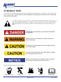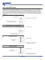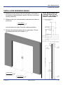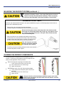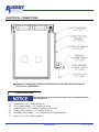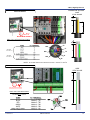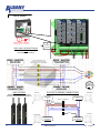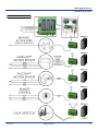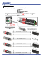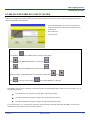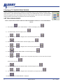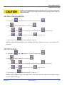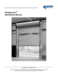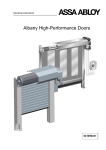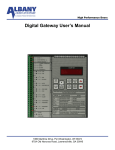
1
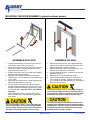
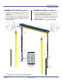
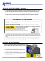
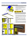
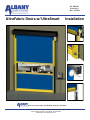
PN: 001010 Version 2.0 Rev: 1/5/2011 UltraFabric Doors w/ UltraSmart Installation Doors are Ultra-Tough, Ultra-Reliable, and Ultra-Affordable. Albany Door Systems - A Company of Albany International Corp. All Rights Reserved 975-A Old Norcross Road, Lawrenceville, Georgia 30046 800-252-2691 www.albanydoors.com INTRODUCTION The contents of this manual are designed to help you operate and maintain Albany UltraLite™, UltraFast™, UltraCool™, and UltraFreeze™ high speed doors. DO NOT operate or perform maintenance on the high speed door unless you have read through the instructions in this manual. The safety alert symbol is used to identify safety information about hazards that can result in personal injury. A signal word (DANGER, WARNING, or CAUTION) is used with the safety alert symbol to indicate the likelihood and the potential severity of injury. In addition, a hazard symbol may be used to represent the type of hazard. DANGER indicates a hazard that, if not avoided, will result in death or serious injury. WARNING indicates a hazard that, if not avoided, could result in death or serious injury. CAUTION indicates a hazard that, if not avoided, might result in minor or moderate injury. CAUTION, when used without the alert symbol, indicates a situation that could result in damage to the door. NOTICE is used to inform you of a method, reference, or procedure that could assist with specific operations or procedures. Other symbols that may be used in this manual are: Lock Out / Tag Out 1 Crushing Fire Manual #001010 Shock Read Manual Rev. 1/5/2011 Albany High Speed Doors Installation & Operation DOOR INSTALLATION TOOLS AND MATERIALS REQUIRED Improper installation of anchoring devices or installation into aged or unsound concrete block, or other wall material may result in premature wear, product failure, property damage, or serious personal injury. Personnel Two people to install the door One person qualified to operate forklift, hoist, or crane Once electrician to install and connect the control panel and all electrical wiring Tools Assorted wrenches Tape measure Carpenter’s square Level (4ft minimum recommended) Lifting device (fork lift, hoist, crane) Lock-Out Tag-out all electrical power supplied to the door before making any electrical installations or connections. Also Lock-out Tag-out any equipment near the installation site if that equipment may be inadvertently operated into the area used to assemble and install the door. Failure to properly deenergize electrical circuits and disable equipment during installation and/or maintenance could result in death or serious injury. Lifting Straps 2 ladders or personnel lifts (tall enough to reach above the door head) Other tools as needed for the type of anchoring chosen Materials Anchors appropriate for the type of wall the door and accessories are to be installed onto. Albany Doors recommends throughbolting doors whenever possible. Wire as specified on the electrical schematic Electrical supplies needed to comply with all regulating body electrical codes and standards. Use proper lifting equipment and techniques. Properly secure all loads. Failure to properly secure all lifting loads could result in death or serious injury. Secure the work area so that persons not working directly on the installation do not enter the work area. SITE PREPARATION Electrical Supply Qualified electrician must make all electrical mountings and connections in accordance with all applicable regulating body(s) electrical codes and standards. The control box is equipped with a 3-phase AC fused disconnect. Door Opening 1. Are the door jambs and support wall structurally sound providing a flat surface for the side columns to mount against? 2. Check the width and height of the door opening and verify the measurements against the dimensions of the door. 3. Is the opening square? Plumb? 4. Is the floor level across the opening? Make all necessary structural repairs and improvements to provide a ―yes‖ answer to each of the questions above. Version 2.0 UNPACKING AND PREPARING 1. Inspect and unpack the components. Report any damage immediately to Albany at (262) 268-9885. Refer to the serial number tag located on the right door column. 2. DO NOT cut the banding which holds the door in a roll until instructed to do so in a later procedure. The door panel and roll assembly could be damaged. Use evenly spaced padded supports to prevent rips, tears, or bending of the roll assembly. Failure to protect the roll assembly could result in damage to the door. Manual #001010 2 WALL ANCHORING GUIDE Albany Doors does not supply hardware for mounting the door to the wall. Use proper hardware best suited for each particular door installation. Some examples are shown below. It is the responsibility of the door owner to ensure that the wall material is strong enough to support the forces of the door and all anchoring hardware. In general, Albany Doors recommends through-bolting wherever possible using 1/2 inch diameter bolts/threaded-rods or 1/2 inch diameter concrete expansion anchors. WOOD, BLOCK, BRICK, or INSULATED WALL CONCRETE, BLOCK, or BRICK WALL INSULATED WALL INSULATED WALL 3 Manual #001010 Rev. 1/5/2011 Albany High Speed Doors Installation & Operation INSTALLATION REFERENCE MARKS 1. Measure from the inside of the left door jamb to the inside of the right door jamb and place a mark on the floor on the door opening centerline. DETAIL BELOW SHOWN FOR STANDARD REAR COLUMN MOUNTING. SEE PAGE 8 FOR UltraLite™ INSTRUCTIONS. 2. Reference the door’s documentation and place two marks on the floor at DoorWidth 2 3 4 " to the left and to the right of the door opening centerline. 3. Measure the distance between the two new marks. The correct distance should be DoorWidth + 1.5‖ DoorWidth 2 Version 2.0 3 4 " DoorWidth 2 3 4 " Manual #001010 4 MOUNTING THE DOOR ASSEMBLY (optional methods shown) ASSEMBLE ON FLOOR ASSEMBLE ON WALL 1. Lay the head assembly on its back on the floor in a clean area in front of the door opening. 2. Remove the bolts securing the yellow front columns to the side columns. Remove and set the yellow front columns off to the side. 3. Position each side column in line with the mounting brackets on the head assembly. 4. Slide the side columns onto the head assembly. Install the three 1/2‖ flat washers, lock washers, and 1/2‖x1‖ bolts. 5. Square the side columns to the head assembly and tighten the three bolts on each side. 6. If the door was ordered with the optional counterweights, slide the weights into the side columns far enough to install the temporary retainer bolt. Install the nut finger-tight. Note the “LEFT” and “RIGHT” markings. 7. Using a safe lifting device, carefully lift the entire door assembly up to a vertical position against the door jambs. 1. Hold the left side column in place against the wall. Align the base with the marking placed on the floor earlier and bring the column into plumb. 2. Mark the locations of the four mounting holes. Prepare the holes and anchor as needed. 3. Loosely install the anchors, recheck for plumb, and tighten the anchors. 4. Repeat steps 1-3 for the right side column. 5. Lay the head assembly on its back on the floor in front of the door opening. Using a safe lifting device, carefully lift the head assembly up into position above the side columns. The door assembly is heavy. Use proper lifting devices and techniques to securely and safely lift the door assembly. Failure to properly secure the door assembly could result in death or serious injury. 5 The head assembly is heavy. Use proper lifting devices and techniques to securely and safely lift the head assembly. Failure to properly secure the head assembly could result in death or serious injury. The head assembly must be lifted level (balanced) and with the mounting brackets and motor hanging straight down. Failure to properly position the head assembly could result in damage to the mounting brackets and/or the side columns. Manual #001010 Rev. 1/5/2011 Albany High Speed Doors Installation & Operation ASSEMBLE ON FLOOR (continued…) ASSEMBLE ON WALL (continued…) 8. Align the base of each side column with the markings place on the floor earlier and bring the columns into plumb. 9. Mark the locations of the mounting holes (4 per side column). Prepare the holes and anchor as needed. 10. Loosely install the anchors, recheck for plumb, and tighten the anchors. 6. Position the head assembly over the side columns with the mounting brackets in line with the side columns and carefully lower it into place. 7. Install the three 1/2‖ flat washers, lock washers, and 1/2‖x1‖ bolts on each side of the head assembly to secure it in place. continue on to step 11 on the following page... 8‖ long temporary counterweight retainer bolt. - INDICATES LOCATION OF FRONT COLUMN MOUNTING BOLT Version 2.0 Manual #001010 6 MOUNTING THE DOOR ASSEMBLY (continued…) 11. The photo safety cables are marked and bundled on top of the head assembly at the junction box. Route the light curtain cables through the holes located at the rear bottom of the mounting brackets as shown. 12. Secure the cables to the sides of the columns using the clips supplied and plug them into the appropriate photo device mounted in the column—note the matching cable markings. Ensure that all loose slack in the cables is removed. Photo devices are located behind foam insulation on UltraFreeze model doors. 13. UltraFreeze doors will have heat tape in the side columns. Route the power cords for the heat tape up through the holes located at the rear bottom of the mounting brackets to the junction box on top of the head assembly. COUNTERWEIGHTS—OPTIONAL EQUIPMENT If the door was ordered with counterweights for the optional BacOut egress system, the following steps must be taken at this point in the installation process: 1. Remove the tie wraps from the counterweight straps and route the straps down to the counterweights. 2. Remove any twists that may be in the straps Do not allow the straps to be twisted or slack. Twisted or loose straps will result in damage to the straps. 3. Loop each strap between the two clamping plates as shown. 4. Pull and hold the straps tight and tighten the clamping bolts. 5. Ensure that all cables/straps are secure and free of any obstructions. 14. Set the yellow front columns into the side columns. If the door was ordered with light curtains, position the front light curtain and mounting bracket against the outside of the side columns and secure the light curtain bracket and the yellow front column with two bolts. Continue installing the remaining bolts provided for each column. 15. Connect the remaining safety cables to the photo safety devices mounted off the yellow front columns and hide the cables behind the wire chase covers on the front columns—note the matching cable markings. 16. Caulk header and door jambs to seal the opening when finished. LEVELING THE DRUM ASSEMBLY The door must be installed to that the roll head assembly is absolutely level, with the side columns plumb and square to the header. If adjustments are necessary… 1. Loosen the pillow block mounting bolts 2. Lift the low end of the roll with a pry bar until the roll is level 3. Re-tighten the pillow block mounting bolts 4. If necessary, loosen the bolt and adjust the motor torque arm position to realign the motor so it is parallel with the wall. Tighten this bolt when done. 7 Manual #001010 Rev. 1/5/2011 Albany High Speed Doors Installation & Operation MOUNTING ULTRALITE AND LOW PROFILE DOORS 1. Lay the head assembly on its back on the floor in a clean area in front of the door opening. 2. Slide each side column onto the head assembly. Install the two 1/2‖ flat washers, lock washers, and 1/2‖x1‖ bolts in each bracket. 3. Using a safe lifting device, carefully lift the entire door assembly up to a vertical position against the door jambs. The head assembly is heavy. Use proper lifting devices and techniques to securely and safely lift the head assembly. Failure to properly secure the head assembly could result in death or serious injury. 4. Position the side columns with the inside face of the black mounting brackets set 3/4‖ out from the door jamb on each side. Ensure the columns are plumb and mark or temporarily fasten the mounting brackets to the wall. 5. Disconnect the side columns from the mounting brackets by removing the 2 bolts in each bracket. 6. Move the columns off the wall. Prepare the holes and permanently anchor the mounting brackets as needed. These brackets could also be welded to a steel jamb. 7. Reattach the side columns to the mounting brackets using the 2 bolts removed from each bracket earlier. 8. Install the head seals to the wall as shown below. 9. Caulk door jambs to seal the opening when finished. Version 2.0 Manual #001010 8 MOUNTING THE DEFROST SYSTEM 1. Lay the components of the defrost system on a clean area in front of the opening on the side of the wall to be installed. When lifting the defrost assembly, position the lifting straps to balance the assembly. 2. Measure and mark the wall for the location of the mounting brackets as shown above Mark a vertical line 21‖ out from the door jamb on the drive side of the door. Mark a vertical line 12‖ out from the door jamb on the non-drive side. Mark a horizontal line intersecting each vertical line 22‖ up from the top of the clear door opening. 1. Place the brackets against the wall inside the alignment marks as shown. Ensure the brackets are plumb. 2. Mark the location of the mounting holes. Prepare the holes and anchor as needed. 3. Mount the defrost components to the wall brackets. Blowers will be centered on opening when properly installed BLOWERS ONLY 9 IR LAMPS ONLY Manual #001010 IR LAMPS AND BLOWERS Rev. 1/5/2011 Albany High Speed Doors Installation & Operation MOUNTING THE DEFROST SYSTEM (continued…) The blower assembly is heavy. Use proper lifting devices and techniques to securely and safely lift the assembly. Failure to properly secure the head assembly could result in death or serious injury. ASSEMBLING IR HEAT LAMPS If the door was ordered with IR Lamps for the optional UltraDefrost system, the following steps must be taken at this point in the installation process: 1. Remove the end cover plates from the lamp fixture 2. Carefully unpack the IR lamp bulbs and red sleeves one at a time. Never touch the glass surface of the lamp bulb or the red sleeve with bare fingers or handle them with a dirty or oily rag. Any debris or oil on the surface of the lamp will lead to a “hot spot” which could cause the lamp to immediately fail. 3. Slide a red sleeve over each bulb and install into each fixture. 4. Connect the wire on the ends of the lamp to the screw terminal located at each end of the fixture. Leave a 1/4‖ loop between the wire on the end of the lamp and the screw terminal. If the 1/4” loops are not made, the bulb can become damaged as it expands upon heating. 5. Cut off any excess wire leading away from each screw terminal once the lamp bulb is wired in place. Direct IR Lamps at the top edge of the bottom bar Loosen the pivot bolt at each end of the fixture Aim the lamp fixture to the desired angle Tighten the pivot bolts Direct Blowers at top 1/2 to 3/4 of door opening height Loosen the pivot bolt and adjusting bolt at each end of the blower Aim the blower unit to the desired angle Tighten all bolts AIM BLOWERS AT TOP 1/2 TO 3/4 OF PANEL The defrost system components must be aligned for proper function. Follow the list of guidelines below and adjust as necessary for the application if frost is present. AIM IR LAMPS AT TOP OF BOTTOM BAR ALIGNING THE DEFROST COMPONENTS Improper direction of the heat lamps towards the upper areas of the panel in near proximity to the lamp could cause the panel to overheat and become damaged. Version 2.0 Manual #001010 10 ELECTRICAL CONNECTIONS REFER TO INDIVIDUAL DOOR SCHEMATICS FOR SPECIFIC DETAILS ON OPTIONAL EQUIPMENT.. CONDUIT ROUTING All conduit and electrical connections must come in through the bottom of the control box. -A-B-C-D-E-F- 11 Motor/Brake—3/4‖ Conduit (all doors) Low Voltage Signals—3/4‖ Conduit (all doors) Defrost Wiring—3/4‖ Conduit (UltraFreeze doors only) Primary Power Supply—3/4‖ Conduit (all doors) Secondary Power Supply—3/4‖ Conduit (some UltraFreeze doors) Floor Loop—1/2‖ Conduit (optional) Manual #001010 Rev. 1/5/2011 Albany High Speed Doors Installation & Operation WIRE STRIP GAUGE MOTOR WIRING ¼‖ 8" 6" ¾” MOTOR WIRE CONDUIT BRAKE WIRES DRILL ONLY INTO BOTTOM OF BOX USE MINIMUM ¾” CONDUIT ¼‖ T2 MG T1 SEPARATE FOIL SHIELD MG SEPARATE FOIL SHIELD T3 6" B1 MG B2 NOTE: MOTOR WIRES TO CHANGE DIRECTION OF MOTOR ROTATION – SWITCH T1 AND T2 ENCODER WIRING WIRE STRIP GAUGE ¼” ¾” LOW VOLTAGE CONDUIT ENCODER, SAFETY, ACTIVATION 4" DRILL ONLY INTO BOTTOM OF BOX USE MINIMUM ¾” CONDUIT TB2 TB3 TB1 TB1 TB4 Version 2.0 Manual #001010 12 SAFETY WIRING ¾” LOW VOLTAGE CONDUIT ENCODER, SAFETY, ACTIVATION H 5 TERMINALS AVAILABLE DRILL ONLY INTO BOTTOM OF BOX USE MINIMUM ¾” CONDUIT BLACK WIRES FROM ALL TRANSMITTERS ARE NOT USED LIGHT CURTAINS RECEIVER TRANSMITTERS - GREEN “POWER” LIGHT ONLY RECEIVERS – STATUS INDICATORS SHOWN BELOW PHOTO EYE WIRING CONNECTIONS RECEIVER #1 MODULE – B TERMINALS BLACK WHITE 2 BROWN 1 BLUE 4 TRANSMITTER TRANSMITTER #1 13 ERROR BLOCKED OK WHITE 3 BLACK RECEIVER TRANSMITTER TRANSMITTER #2 (optional) Manual #001010 RECEIVER #2 (optional) Rev. 1/5/2011 Albany High Speed Doors Installation & Operation ACTIVATION WIRING Version 2.0 Manual #001010 14 DEFROST WIRING Albany doors may be equipped with one of the following optional systems: · · · · Heated Blowers IR Lamps IR Lamps & Unheated Blowers Unheated Blowers Use 18AWG or larger wires for all connections to RED terminal blocks. Use 12AWG or larger wires for all connections to BLACK terminal blocks. ¾” DEFROST WIRE CONDUIT DRILL ONLY INTO BOTTOM OF BOX CONNECT TERMINALS 28 & 29 TO 120VAC HEAT TAPE USE MINIMUM ¾” CONDUIT LOCATED IN JUNCTION BOX ON HEADER 6 LOW VOLTAGE WIRES - 13, 14, 15, 16, 17, 18 HEA TED BL OWE RS 6 HIGH VOLTAGE WIRES - 19, 20, 21, 22, 23, 24 3 IR LA MPS HIGH VOLTAGE WIRES - 25, 26, 27 4 UNH LOW VOLTAGE WIRES - 13, 14, 16, 17 IR L EAT AMPS ED B LOW ERS 9 HIGH VOLTAGE WIRES - 19, 20, 21, 22, 23, 24, 25, 26, 27 UNH 4 LOW VOLTAGE WIRES - 13, 14, 16, 17 EAT ED B L OWE RS 6 HIGH VOLTAGE WIRES - 19, 20, 21, 22, 23, 24 15 Manual #001010 Rev. 1/5/2011 Albany High Speed Doors Installation & Operation ENABLING THE WIRELESS SAFETY SYSTEM If the door is equipped with Albany’s Wireless Safety System (indicated by the lack of a coil cord), the following steps must be taken to initialize the communications: 1. Locate the RFID number on a sticker on the pull strip. 2. Setup the UltraSmart™ Controller according to the procedure below: 3. Pull out the strip. 4. Test the system. UltraSmart™ Controller Settings Press and hold until ―LIMIT SETUP‖ is shown on the display Press until ―WIRELESS SETUP‖ is shown; Press Press until ―BOTTOM BAR ID‖ is shown; Press Change the number to the RFID number on the bottom bar label using Press to store the value and press and until ―DOOR READY‖ is displayed Thoroughly test the system to determine if all sensors/switches are functioning properly. Make sure you can answer ―yes‖ to the following questions: Does the door reverse when the reversing edge is tripped upon closing? Does the UltraSmart™ controller recognize the left-side breakaway switch? Does the UltraSmart™ controller recognize the right-side breakaway switch? If you cannot answer ―yes‖ to all the above questions, check all wiring connections and ensure the RFID is set to the same number that is labeled on the wireless bottom bar module. Version 2.0 Manual #001010 16 UltraSmart™ STARTUP PROCEDURE Albany’s UltraSmart™ control system is designed to accommodate numerous option modules and future technological advances. This manual will address necessary settings for the standard options; however, optional modules and special applications may require additional steps to be taken for proper setup. Refer to the control schematic shipped inside the panel enclosure for additional electrical and setup details. SETTING DOOR LIMITS NOTE: SAFETY DEVICES WILL PREVENT THE DOOR FROM CLOSING IF ACTIVATED DURING SETUP 1) Press and hold until ―LIMIT SETUP‖ is shown on the display; Press 2) ―CLOSED LIMIT‖ should be displayed; Press 3) Use 4) Press 5) Use 6) Press 7) Use and/or to bring the door to the full closed position; Press ―FULL OPEN LIMIT‖ should be displayed; Press and/or to bring the door to the full open position; Press ―PARTIAL OPEN LIMIT‖ should be displayed; Press and/or to bring the door to the partial open position or set the same as the full open position if not used; Press 8) Press 9) Use 10) Press 17 ―BREAKAWAY RESET LIMIT‖ should be displayed; Press and/or to bring the door to the breakaway reset position; Press until ―DOOR READY‖ is displayed Manual #001010 Rev. 1/5/2011 Albany High Speed Doors Installation & Operation The Open, Partial, and Breakaway Limit are all relative to the Closed Limit. If the Closed Limit is reset to a different position, all other limit settings will change relative to the new Closed Limit setting. SETTING SYSTEM OPTIONS 1) Press and hold 2) Press until ―LIMIT SETUP‖ is shown on the display; Press until ―SYSTEM OPTIONS‖ is shown; Press Use and/or to cycle through the available options; Press Use and/or to change the value; Press 3) When finished—press to edit that option. to store that value until ―DOOR READY‖ is displayed Commonly changed SYSTEM OPTIONS include: “RevEdge Auto Close?”, “Photoeye Auto Close?”, “Panel Open MAN1 Auto Close?” SETTING TIMERS 1) Press and hold 2) Press until ―LIMIT SETUP‖ is shown on the display; Press until ―SET TIMERS‖ is shown; Press Use and/or to cycle through the available options; Press Use and/or to change the value; Press 3) When finished—press to edit an option. to store that value until ―DOOR READY‖ is displayed Commonly changed TIMERS include: “Close Delay, Auto1”, “Door Open Alarm Tmr”, “Delay-To-Close Outpt”, “Defrost Cycle On”, “Defrost Cycle Off” Version 2.0 Manual #001010 18 Installation Checklist Please fill out below and return to Albany Door Systems Customer: Installation Date(s): Location: Door Serial #(‘s): Contact: Contact Phone #: Install Company: Contact & Phone #: Mechanical Installation (All Doors): Yes No Yes No Is the door secured to the wall using thru-bolts? If No, what type of anchors were used? Is the door roll and rear spreader level? Are the side columns plumb? Does the door have counterweights? If Yes, are the straps routed properly? Is the door caulked or sealed to the wall? Are there any visible gaps between the door and the wall? If ―No‖ the above, did the customer contact approve of door to wall seal? Is there any visible damage to the door? If Yes, what is the damage: Was Albany Customer Service notified of the damage? Was the customer contact notified of the damage? UltraFreeze Doors: What type of defrost system is on the door? Are the defrost mounting brackets anchored to the wall using thru-bolts? If No, what type of anchors were used? Is the defrost mounting bracket level and plumb? Does the door have blowers? If Yes, are the blowers aimed towards the top half of the door panel? Does the door have heat lamps? If Yes, are the heat lamps aimed properly (at the bottom bar)? If No, what is the reason? 19 Manual #001010 Rev. 1/5/2011 Albany High Speed Doors Installation & Operation Yes No Electrical Installation: Were the factory supplied cables (motor, encoder & 7 – wire) cables long enough? If No, which cables were too short? If No, was Albany Customer Support contacted and new cables sent? Were the schematics easy to read for electrical hook-up? What type of conduit was used to route the cables to the door? Is the conduit routed to the bottom of the control box? If ―No‖ did the customer approve this? If ―No,‖ why? If ―Yes,‖ who was the customer contact that approved? Door Start-up Yes No Was the door start-up procedure easy to follow? If No, what problem(s) did you run into? Was Albany Customer Support Dept. notified of these issues? Is the Reversing Edge working? Are the front and rear light curtains (or photo-eyes) working? Do the bottom bar breakaway switches work? Does the door’s self-repair feature work when the door is broken away? If the door has counterweights, does the egress work? Activation What type of activation is being used? Was the activation supplied by Albany? Did the customer approve of the mounting and operation of the activators? Comments Version 2.0 Manual #001010 20 Albany Door Systems - A Company of Albany International Corp. All Rights Reserved 975-A Old Norcross Road, Lawrenceville, Georgia 30046 800-252-2691 www.albanydoors.com