1
PT110N/PT110N-XT
Vandal Resistant 10x PTZ Dome
User Manual
NY: 55 Mall Drive • Commack, NY 11725 (800) 422-6707
CA: 20521 Earl Street • Torrance, CA 90503 (800) 888-0131
www.computarganz.com
CONTENTS
○1 Introduction
Features
3
Product & Accessories
5
Parts Name & Functions
7
○2 Installation
DIP Switch Setup
8
Installation using Ceiling Mount Bracket
11
Installation using Wall Mount Bracket
12
Installation using Flush Mount Bracket
13
Cabling
14
Check Points before Operation
17
Preset and Pattern Function Pre-Check
17
Starting OSD Menu
18
Reserved Preset
18
Preset
19
○3 Operation
Swing
19
Pattern
20
Group
21
Other Functions
22
OSD Display of Main Screen
23
○4 How to use OSD Menu
General Rules of Key Operation for Menu
24
Main Menu
24
Display Setup
25
Privacy Zone Mask Setup
26
Camera Setup
27
Motion Setup
30
Preset Setup
32
Swing Setup
33
Pattern Setup
34
Group Setup
35
System Initialize
37
○5 Specifications
38
Dimensions
39
INTRODUCTION
1
Features
Camera Specifications
: 1/4" Interline Transfer CCD
z
CCD Sensor
z
Zoom Magnification : × 10 Optical Zoom, × 10 Digital Zoom (Max × 100 Zoom)
z
Day & Night Function
z
Variable Focus Mode: Auto-Focus / Manual Focus / Semi-Auto Focus.
z
Independent & Simultaneous Camera Characteristic Setup in Preset operation
Advanced Pan/Tilt Functions
z
Max. 360°/sec high speed Pan/Tilt Motion
z
Using Vector Drive Technology, Pan/Tilt motions are accomplished with the shortest path. As a result,
time to target view is reduced dramatically and the video stream transfers are natural to watch.
z
For jog operation using a controller, an ultra slow speed of 0.05°/sec can be reached, making it very
easy to relocate camera to the desired target view. Additionally, it is easy to move the camera to a
desired position with zoom-proportional pan/tilt movement.
.
Preset, Pattern, Swing, Group, Privacy Mask and More…
z
Max. 127 Presets are assignable and characteristics of each preset can be set up independently, such as
White Balance, Auto Exposure, Label and so on.
z
Max. 8 set of Swing actions can be stored. This enables camera to move automatically between two
preset positions at a designated speed.
z
Max. 4 Patterns can be recorded and played back. This enables camera to automatically follow any
trajectory preset by joystick as closely as possible.
z
Max. 8 set of Group action can be stored. This enables camera to move automatically with a
combination of Preset or Pattern or Swing. A Group is composed of max. 20 entities of Preset/
Pattern/Swings.
z
Privacy Masks are assignable, so as not to intrude on other’s privacy. (4 Privacy Zones)
PTZ (Pan/Tilt/Zoom) Control
z
With RS-485 communication, max. of 255 cameras can be controlled at the same time.
z
Pelco-D or Pelco-P protocol can be selected as a control protocol in the current firmware version.
Speed Dome Camera Instruction Manual
3
INTRODUCTION
1
OSD (On Screen Display) Menu
z
OSD menu is provided to display the status of camera and to configure the functions interactively.
z
The information such as Camera ID, Pan/Tilt Angle, Alarm Input and Preset can be displayed on screen.
Alarm I/O Functions
z
4 alarm sensor Inputs are available.
z
To completely eliminate external electric noise and shock, alarm sensor Input is decoupled from photo
coupler.
z
If an external sensor is activated, camera can be set to move to the corresponding Preset position.
Reserved Presets for Special Purpose
z
Most camera characteristics can be set up easily and directly with reserved preset, without entering the
OSD menu. For more information, refer to “Reserved Preset” in this manual.
IP66 (weather resistant)
z
*(PT110N-XT model only).
This product has been certified to the IP66 standard for waterproof and spray proof environments. Also
for the same reason it can be protected from dust and rainstorms.
Speed Dome Camera Instruction Manual
4
INTRODUCTION
1
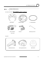
Product & Accessories
Product & Accessories- PT110N-XT
model (outdoor).
z Main Body
z Mount Adapter
z Terminal Block
z Screws
z
Gasket(Rubber)
z Six angles wrench
Video cable
Options
z Wall Mount Bracket
Speed Dome Camera Instruction Manual
z Ceiling Mount Bracket
z Sun shield
5
INTRODUCTION
Product & Accessories-
1
PT110N model (indoor).
z Main Body
z Surface Mount Bracket
z Screws & Terminal Block
Options
z In-Ceiling Mount Bracket
Speed Dome Camera Instruction Manual
z Ceiling Mount Bracket
z Wall Mount Bracket
6
INTRODUCTION
1
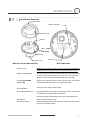
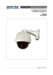
Parts Name & Functions
Mount Adapter
Cabling Terminal Block
Safety Retention Spring
Main Body
Gasket
(PT110N-
XT Model only)
Lock-up Screw
Dome Cover
DIP Switch
Main Unit / Surface Mount Bracket
z Dome Cover
Back of Main Unit
Do not remove protective vinyl from dome cover before finishing all
installation processes to protect dome cover from scratches or dust.
z Surface Mount Bracket
The surface mount bracket is used for installing either a ceiling mount
or wall mount bracket. Separate the cover first and then attach it
directly to ceiling. Camera must be assembled at the last stage.
z Gasket (PT110N-XT
Protect it from dust and rainstorm. Move projecting part of the gasket
model only)
which should be placed on the low to main body position
z Lockup Screw
z Cabling Terminal Block
Fixes main unit to surface mount bracket.
During installation, Power, Video, Communication, Alarm Input cables
are connected on to this cabling terminal block.
Pull out from Surface Mount Bracket and connect to Main Body hook.
z DIP Switch
Adjusts camera ID and protocols.
z Fall-proof spring
After installing fall-proof spring on Bracket , hang on the safety ring to
Speed Dome Camera Instruction Manual
protect the camera from falling
7
2
INSTALLATION
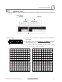
DIP Switch Setup
Before you install the camera, you should set the DIP switches to configure the camera ID and communication
protocol.
Camera ID Setup
ON
z
shown below.
ON
z
1
The ID number of camera is set using a binary number. Examples
2
3
4
5
6
7
The range of ID is 1~255. Do not use 0 as camera ID. Factory
default of Camera ID is 1.
8
z
If you want to control a certain camera, you must match the camera
ID with Cam ID setting of DVR or Controller.
Pin
1
2
3
4
5
6
7
8
Pin
1
2
3
4
5
6
7
8
ID
1
2
4
8
16
32
64
128
ID
1
2
4
8
16
32
64
128
1
on
off
off
off
off
off
off
off
11
on
on
off
on
off
off
off
off
2
off
on
off
off
off
off
off
off
12
off
off
on
on
off
off
off
off
3
on
on
off
off
off
off
off
off
13
on
off
on
on
off
off
off
off
4
off
off
on
off
off
off
off
off
14
off
on
on
on
off
off
off
off
5
on
off
on
off
off
off
off
off
15
on
on
on
on
off
off
off
Off
6
off
on
on
off
off
off
off
off
16
off
off
off
off
on
off
off
off
7
on
on
on
off
off
off
off
off
17
on
off
off
off
on
off
off
off
8
off
off
off
on
off
off
off
off
18
off
on
off
off
on
off
off
off
9
on
off
off
on
off
off
off
off
19
on
on
off
Off
on
off
off
off
10
off
on
off
on
off
off
off
off
20
off
off
on
off
on
off
off
off
Speed Dome Camera Instruction Manual
8
2
INSTALLATION
Pin
1
2
3
4
5
6
7
8
Pin
1
2
3
4
5
6
7
8
ID
1
2
4
8
16
32
64
128
ID
1
2
4
8
16
32
64
128
21
on
off
on
off
on
off
off
off
31
on
on
on
on
on
off
off
off
22
off
on
on
off
on
off
off
off
32
off
off
off
off
off
on
off
off
23
on
on
on
off
on
off
off
off
33
on
off
off
off
off
on
off
off
24
off
off
off
on
on
off
off
off
34
off
on
off
off
off
on
off
off
25
on
off
off
on
on
off
off
off
35
on
on
off
off
off
on
off
Off
26
off
on
off
on
on
off
off
off
36
off
off
on
off
Off
on
off
off
27
on
on
off
on
on
off
off
off
37
on
off
on
off
Off
on
off
off
28
off
off
on
on
on
off
off
off
38
off
on
on
off
Off
on
off
off
29
on
off
on
on
on
off
off
off
39
on
on
on
off
Off
on
off
off
30
off
on
on
on
on
off
off
off
40
off
off
off
on
Off
on
off
off
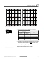
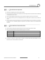
Communication Protocol Setup
ON
z
ON
Select the appropriate Protocol with DIP switch combination.
Switch State
1
2
3
4
z
P0
(Pin 1)
P1
(Pin 2)
Protocol
OFF
OFF
PELCO-D, 2400 bps
ON
OFF
PELCO-D, 9600 bps
OFF
ON
PELCO-P, 4800 bps
ON
ON
PELCO-P, 9600 bps
If you want to control using DVR or P/T controller, their protocol must
be identical to camera. Otherwise, you cannot control the camera.
z
If you changed camera protocol by changing DIP S/W, the change
will be effective after you reboot the camera.
z
Factory default of protocol is “Pelco-D, 2400 bps”.
Reserved for Supplier
Speed Dome Camera Instruction Manual
9
INSTALLATION
ON
z
ON
2
Pin 3 is only for supplier, DO NOT CHANGE THESE ITS ORIGINAL
STATE. If you change one of these, proper operation can not be
achieved.
1
2
3
4
~ Pin 3
PAL / NTSC system selection of Camera. DO NOT
CHANGE THIS PIN.
Terminal Resistor Setup
ON
Terminal resistor is used if your system meets one of following two
ON
conditional cases.
1
2
3
4
z
Case1: Control cable between camera and controller is
relatively long (1:1 connection)
If communication cable is very long, the electrical signal will bind in
the terminal point. This reflected signal causes signal distortion,
resulting in a degradation of camera function. In this case, the
terminal resistor of both sides (i.e. camera and controller) must be
set to the ‘ON’ state.
z
Case2: Multiple cameras are controlled at the same time
Due to similar reasons stated in case 1, the terminal resisters of the
controller and the last camera must be set to ‘ON’ state.
The
camera with the longest cable length is determined to be the ‘last’
camera. Do not turn on the terminal resistor of all cameras.
Controller
Terminal Resistor ON
RS-485
#1
#2
Terminal Resistor Terminal Resistor
OFF
OFF
Speed Dome Camera Instruction Manual
#n
Terminal Resistor
ON
10
INSTALLATION
2
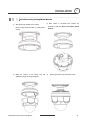
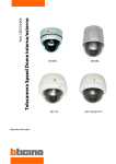
Installation using Ceiling Mount Bracket
①
After putting the Gasket on the ceiling
Fasten ceiling mount bracket to ceiling with 3
screws.
①
Hang the camera on the safety ring and
② Wire cables to terminals and connect the
terminals to main unit. Do not use surface mount
bracket!
②
Remove protective vinyl from dome cover.
assemble it using the fall-proof spring.
Speed Dome Camera Instruction Manual
11
2
Installation using Wall Mount Bracket
①
After putting the Gasket on the wall
② Wire cables to terminals and connect the
terminals to main unit. Do not use surface
Fasten wall mount bracket to ceiling with 4
mount bracket!
screws.
③
Fasten main unit to wall mount bracket with 4
④
Remove protective vinyl from dome cover.
screws.
Speed Dome Camera Instruction Manual
12
INSTALLATION
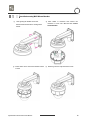
2
Installation using Flush Mount Bracket
①
Cut 3 holes in ceiling
②
Align main body bracket with flush mount
bracket. Fasten with screws.
.
③
Connect fall-proof spring to main body
hook. Assemble and fasten with screws.
⑤
Secure flush mount bracket to the ceiling
with screws through the 3 holes on the
④
Put main body and bracket assembly into
main hole.
⑥ Cover assembly with bracket
cover and turn it clockwise.
bracket.
Speed Dome Camera Instruction Manual
13
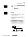
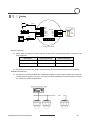
Cabling
Power
PWR(+)
PWR(-)
F.G
RS-485(+)
RS-485(-)
VIDEO(+)
VIDEO(-)
Controller/ DVR
IrDA
Sensor
IN COM+
IN1
IN2
IN3
IN4
Door
Switch
BNC
Sensor
Moinitor
Cabling Terminal Block
Power Connection
z
Please check the voltage and current capacity of rated power carefully. Rated power is indicated on the
back of main unit.
z
Rated Power
Input Voltage Range
Current Consumption
AC 24V (PT110N)
AC 17V ~ 29V
0.4 A
AC 24V (PT110N-XT)
AC 17V ~ 29V
1.5 A
DC power loss increases over distance. DC power wiring to cameras should be kept as short as possible.
RS-485 Communication
z
For PTZ control, connect the RS-485 line to keyboard and DVR. To control multiple cameras on the same line
with simultaneous operation (see page 13 for resistor settings): the RS-485 communication lines to cameras
are connected in parallel as shown below.
Speed Dome Camera Instruction Manual
14
INSTALLATION
2
Video Connection
z
Connect with BNC coaxial cable.
Alarm Input Connection
z
Sensor Input
Internal
SENSOR IN1
SENSOR COM
(GND)
SENSOR IN2
SENSOR COM
(GND)
SENSOR IN3
SENSOR COM
(GND)
SENSOR IN4
SENSOR COM
(GND)
Before connecting sensors, check the sensor driver voltage and output signal type. Since sensor output
signal types are divided into Open Collector and Voltage Output types in general, the cabling must be
installed properly depending on the signal type.
Signal
IN COM+
Description
Connect (+) cable of electric power source for Sensors to this port as
shown in the circuit above.
IN1−, IN2−, IN3−, IN4−
Speed Dome Camera Instruction Manual
Connect output of sensors for each port as shown in the circuit above.
15
INSTALLATION
2
If you want to use Alarm Input, the type of sensor must be selected in OSD menu. The sensor types are
Normal Open and Normal Close. If the sensor type is not selected properly, alarm activation will occur
opposite of what is desired.
~ Normal Open
Output Voltage is high state when sensor is activated
~ Normal Close
Output Voltage is high state when sensor is not activated
Speed Dome Camera Instruction Manual
16
OPERATION
3
Check Points before Operation
z
Before power is applied, please check the cables carefully.
z
The camera ID of the controller must be identical to that of the target camera. The camera ID can be checked by
reading DIP switch of the camera.
z
If your controller supports multi-protocols, the protocol must be changed to match to that of the camera.
z
If you changed camera protocol by changing DIP switch, the change will be effective after you reboot the
camera.
z
Since the operation method can be different for each controller available, refer to the manual for your controller
if camera can not be controlled properly. The operation of this manual is based on the standard Pelco®
Controller.
Preset and Pattern Function Pre-Check
z
Check controller or DVR preset and pattern functions in advance when using controller or DVR.
z
Refer to the following table when using standard Pelco® protocol controller.
z
< Go Preset >
Input [Preset Number] and press [Preset] button.
< Set Preset >
Input [Preset Number] and press [Preset] button for more than 2 seconds.
< Run Pattern >
Input [Pattern Number] and press [Pattern] button.
< Set Pattern >
Input [Pattern Number] and press [Pattern] button for more than 2 seconds.
If controller or DVR has no pattern button or function, use shortcut keys with preset numbers. For more
information, refer to “Reserved Preset” in this manual.
Speed Dome Camera Instruction Manual
17
OPERATION
3
Starting OSD Menu
z Function
Using the OSD menu, Preset, Pattern, Swing, Group and Alarm Input function can be
configured for each application
z Enter Menu
<Go Preset> [95]
Reserved Preset
z Description
z Function
Some Preset numbers are reserved to special functions.
Go Preset [95]
: Enters into OSD menu
Go Preset [131~134]
: Runs Pattern Function 1 ~ 4
Go Preset [141~148]
: Runs Swing Function 1 ~ 8
Go Preset [151~158]
: Runs Group Function 1 ~ 8
Go Preset [170]
: Sets Camera BLC Mode to OFF
Go Preset [171]
: Sets Camera BLC Mode to ON
Go Preset [174]
: Sets Camera Focus Mode to AUTO
Go Preset [175]
: Sets Camera Focus Mode to Manual
Go Preset [176]
: Sets Camera Focus Mode to SEMI-AUTO
Go Preset [177]
: Sets Day & Night Mode to AUTO
Go Preset [178]
: Sets Day & Night Mode to NIGHT
Go Preset [179]
: Sets Day & Night Mode to DAY
Go Preset [190]
: Sets OSD Display Mode to AUTO (Except Privacy Mask)
Go Preset [191]
: Sets OSD Display Mode to OFF (Except Privacy Mask)
Go Preset [192]
: Setting OSD Display Mode to ON (Except Privacy Mask)
Go Preset [193]
: Sets all Privacy Mask Display to OFF
Go Preset [194]
: Sets all Privacy Mask Display to ON
Speed Dome Camera Instruction Manual
18
OPERATION
3
Preset
z Function
Max. 127 positions can be stored as Preset position. The Preset number can be
assigned from 1 to 128, but 95 is reserved for starting OSD menu.
Camera characteristics (i.e. White Balance, Auto Exposure) can be set up
independently for each preset. Label should be blank and "Camera Adjust" should be
set to "GLOBAL" as default. All characteristics can be set up in OSD menu.
z Set Preset
<Set Preset> [1~128]
z Run Preset
<Go Preset> [1~128]
z Delete Preset
To delete Preset, use OSD menu.
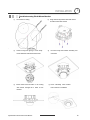
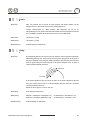
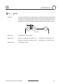
Swing
z Function
By using Swing function, the camera can move between 2 Preset positions repeatedly.
When swing function runs, camera moves from the preset assigned as the 1st point to
the preset assigned as the 2nd point in CW (Clockwise) direction. Then camera moves
from the preset assigned as the 2nd point to the preset assigned as the 1st point in
CCW (Counterclockwise) direction.
1
1st Preset
CW
n
io
ct
re
i
D
2
W
CC
2nd Preset
ion
ct
re
i
D
If the preset assigned as the 1st point is the same as the preset assigned as the 2nd
point, the camera will turn 360° in a CW (Clockwise) direction, then 360° in a CCW
(Counterclockwise) direction.
Speed can be set up from 1°/sec to 180°/sec.
z Set Swing
To set Swing, use OSD menu.
z Run Swing
Method 1) <Run Pattern> [Swing NO.+10]
ex) Run Swing 3 : <Run Pattern> [13]
Method 2) <Go Preset> [Swing NO.+140]
ex) Run Swing 3 : <Go Preset> [143]
z Delete Swing
To delete Swing, use OSD menu.
Speed Dome Camera Instruction Manual
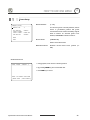
19
OPERATION
3
Pattern
z Function
Pattern Function allows the camera to memorize a path (often a curved path) created
by controller joystick for an assigned time. The camera will then retrace the path
exactly as memorized.
4 Patterns are available and Maximum 1200 communication commands can be stored
in a pattern.
z Set Pattern
Patterns can be created by one of following two methods.
Method 1) <Set Pattern> [Pattern NO.]
{
Pattern editing screen is displayed as bellow.
EDIT PATTERN 1
[NEAR:SAVE
/FAR:DELETE]
0/0/x1/N
{
Movement by Joystick and preset movement can be memorized in a pattern.
{
The remaining memory size is displayed in progress bar.
{
To save the recording, press NEAR key and to cancel, press FAR key.
Method 2) OSD Using OSD Menu: See the section “How to use OSD Menu”.
z Run Pattern
z Delete Pattern
Method 1) <Run Pattern> [Pattern NO.]
ex) Run Pattern 2 : <Run Pattern> [2]
Method 2) <Go Preset> [Pattern NO.+130]
ex) Run Pattern 2: <Go Preset> [132]
Use OSD menu to delete a Pattern.
Speed Dome Camera Instruction Manual
20
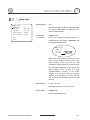
OPERATION
3
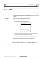
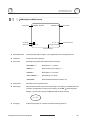
Group
z Function
The group function allows a running sequence of Presets, Pattern and/or Swings. Max
8 groups can be stored. Each group can have max 20 action entities which can be
preset, pattern or swing. Preset speed can be set up and the repeat number of Pattern
& Swing can be set up in Group setup. Dwell time between actions can also be set up.
Dwell Time
Preset 1
Pattern 1
Swing 1
Max 20 Entities
z Set Group
Use OSD Menu to create a Group.
z Run Group
Method 1) <Run Pattern> [Group NO.+20]
ex) Run Group 7 : <Run Pattern> [27]
Method 2) <Go Preset> [Group NO.++150]
ex) Run Group 7 : <Go Preset> [157]
z Delete Group
Use OSD Menu to delete.
Speed Dome Camera Instruction Manual
21
OPERATION
3
Other Functions
z Power Up Action
This function enables the camera to resume the last action executed before power
down. Most actions such as Preset, Pattern, Swing and Group are available for this
function, but Jog actions cannot be resumed.
z Auto Flip
If the tilt angle arrives at the top of tilt orbit (90°), zoom module camera will keep
moving in the opposite tilt direction (180°) to keep tracing targets. As soon as the
camera (lens) passes through the top of tilt direction (90°), images will be reversed
automatically and the F symbol appears on screen. If this function is set to OFF, tilt
movement range is 0 ~ 95°.
z Parking Action
This function sets the camera to a specific position automatically if operator doesn’t
operate the controller for a while. The Park Time can be defined as an interval from 1
minute to 4 hours.
z Alarm Input
4 Alarm Inputs are used. If an external sensor is activated, camera can be set to move
to corresponding preset position. Note: the latest alarm input is in effect if multiple
sensors are activated.
z Privacy Zone Mask
To protect privacy, MAX. 4 Privacy Masks can be created in arbitrary locations to hide
objects such as windows, shops or private houses. With the Spherical Coordinates
system, a powerful Privacy Zone Mask function is available.
z GLOBAL/LOCAL
Image Setup
WB (White Balance) and AE (Auto Exposure) can be set up independently for each
preset. There are 2 modes, "Global" mode & "Local" mode. The Global mode means
that WB or AE can be set up simultaneously for all presets in the "ZOOM CAMERA
SETUP" menu. The Local mode means that WB or AE can be set up independently or
separately for each preset in each preset setup menu. Each Local WB/AE value will
activate correspondingly as the camera arrives at each preset location.
During jog operation, Global WB/AE values should be applied. All Local WB/AE
values will not change although Global WB/AE value changes.
z Semi-Auto Focus
Automatically selects focus mode from Manual Focus or Auto Focus depending on type
of operation. Manual Focus mode activates in preset operation and Auto Focus mode
activates during jog operation. In Manual mode, Focus data for each preset is
memorized in advance, and the camera calls focus data for corresponding presets as
soon as it arrives at a preset. This method shortens focus times.
Focus mode changes to Auto Focus mode automatically when jog operation starts.
Speed Dome Camera Instruction Manual
22
OPERATION
3
OSD Display of Main Screen
Preset Label
Image Flip
Camera ID
LABEL12345
F
CAM 1
PRESET1
I:1--4
15/4/x1/N
Action Title
Alarm Information
P/T/Z Information
z
P/T/Z Information
Current Pan/Tilt angle in degree, zoom magnification and a compass direction.
z
Camera ID
Current Camera ID (Address).
z
Action Title
Followings are possible Action Titles and their meaning.
"SET PRESET ×××"
When Preset ××× is stored
"PRESET ×××"
When camera reach to Preset ×××
"PATTERN ×"
When Pattern × is in action
"SWG×/PRESET ×××"
When Swing × is in action
"UNDEFINED"
When undefined function is called to run
z
Preset Label
The Label stored for specific Preset.
z
Alarm Input
This information shows current state of Alarm Input. If an Input point is ON it will show
a number corresponding to each point. If an Input point is OFF, '-' will be displayed.
Example - if points 2 & 3 of inputs are ON, the OSD will show as below:
I:-23-
z
Image Flip
Indicates that images are currently reversed by Auto Flip Function.
Speed Dome Camera Instruction Manual
23
HOW TO USE OSD MENU
4
General Rules of Key Operation for Menu
z
The menu items surrounded with (
) always have a sub menu.
z
At all menu levels, to go into sub menu, press NEAR key.
z
To go to up one menu level, press FAR key.
z
To move from items to item in the menu, use joystick in the Up/Down or Left/Right.
z
To change a value of an item, use Up/Down of the joystick in the controller.
z
Press NEAR key to save values and Press FAR key to cancel values.
Main Menu
SPEED DOME CAMERA
-----------------------<SYSTEM INFORMATION>
<DISPLAY SETUP>
<DOME CAMERA SETUP>
z System Information
system
information
and
configuration.
z Display Setup
Enable/Disable of OSD display on Main
Screen.
<SYSTEM INITIALIZE>
z Dome Camera Setup
EXIT
Displays
z System Initialize
Configure various functions of this camera.
Initializes system configuration and sets all
data to factory default configuration.
Speed Dome Camera Instruction Manual
24
HOW TO USE OSD MENU
4
Display Setup
DISPLAY SETUP
-----------------------CAMERA ID
ON
PTZ INFORMATION
AUTO
ACTION TITLE
AUTO
PRESET LABEL
AUTO
ALARM INPUT
AUTO
<SET NORTH DIRECTION>
<PRIVACY ZONE>
BACK
EXIT
This menu defines Enable/Disable of OSD display on Main Screen. If an
item is set to be AUTO, the item is displayed only when the value of it is
changed.
z Camera ID
[ON/OFF]
z PTZ Information
[ON/OFF/AUTO]
z Action Title
[ON/OFF/AUTO]
z Preset Label
[ON/OFF/AUTO]
z Alarm Input
[ON/OFF/AUTO]
Compass Direction Setup
SET NORTH DIRECTION
------------------------
Set North to assign compass direction as criteria. Move camera and
press NEAR button to save.
MOVE TO TARGET POSITION
[NEAR:SAVE
/FAR:CANCEL
Speed Dome Camera Instruction Manual
25
HOW TO USE OSD MENU
4
Privacy Zone Mask Setup
PRIVACY ZONE
-----------------------MASK NO
1
UNDEFINED
DISPLAY
OFF
CLEAR MASK
CANCEL
<EDIT MASK>
Select area in image to mask.
z Mask No
[1~4]
Select Mask number. If the selected mask has
already data, camera moves as it was set.
Otherwise, “UNDEFINED” will be displayed
under “Mask NO”.
BACK
EXIT
z Display
[ON/OFF]
Sets if camera makes mask shows or not on
images.
z Clear Mask
[CANCEL/OK]
Deletes data in the selected mask NO.
Privacy Zone Area Setup
EDIT MASK 1
------------------------
Move camera to area to mask. Then the menu to adjust mask size will be
displayed.
MOVE TO TARGET POSITION
[NEAR:SELECT/FAR:CANCEL]
Privacy Zone Size Adjustment
EDIT MASK 1
------------------------
[
[
:ADJUST MASK WIDTH]
:ADJUST MASK HEIGHT]
[NEAR:SAVE
Adjust mask size. Use joystick or arrow buttons to adjust mask size.
z (Left/Right)
z (Left/Right)
z (Up/Down)
z (Up/Down)
/FAR:CANCEL]
Speed Dome Camera Instruction Manual
26
HOW TO USE OSD MENU
4
Camera Setup
ZOOM CAMERA SETUP
-----------------------FOCUS MODE
SEMIAUTO
DIGITAL ZOOM
ON
LINE LOCK
OFF
IMAGE FLIP
OFF
<WHITE BALANCE SETUP>
<AUTO EXPOSURE SETUP>
Setup the general functions of zoom camera module.
z Focus Mode
[AUTO/MANUAL/SEMIAUTO]
Sets camera focus mode.
{ SEMIAUTO Mode
Automatically
selects
focus
mode
from
Manual Focus or Auto Focus depending on
BACK
EXIT
type of operation. Manual Focus mode
activates in preset operation and Auto Focus
mode activates during jog operation. In
Manual mode, Focus data for each preset is
memorized in advance, and the camera calls
focus data for corresponding presets as soon
as it arrives at a preset.
z Digital Zoom
[ON/OFF]
Sets digital zoom function to ON/OFF. When
set to OFF, optical zoom function runs but
zoom function stops at the end of optical zoom
magnification.
z Line Lock
[ON/OFF]
If Line lock sync is ON, video signal is
synchronized with AC power. Video can be
fluctuated after setting is changed.
zImage Flip
[ON/OFF]
Turn watching direction to the other side of
moving when camera gets vertical sight.
Speed Dome Camera Instruction Manual
27
HOW TO USE OSD MENU
4
White Balance set up
WB SETUP - GLOBAL
-----------------------WB MODE
AUTO
RED
ADJUST
--BLUE ADJUST
---
BACK
EXIT
Speed Dome Camera Instruction Manual
z WB Mode
[AUTO/MANUAL]
In Manual mode, Red and Blue level can be
set up manually
z Red Adjust
[10~60]
z Blue Adjust
[10~60]
28
HOW TO USE OSD MENU
4
Auto Exposure Setup
z Backlight
[ON/OFF]
Sets Backlight Compensation
AE SETUP - GLOBAL
-----------------------BACKLIGHT
OFF
DAY/NIGHT
AUTO1
BRIGHTNESS
25
IRIS
AUTO
SHUTTER
ESC
AGC
NORMAL
SSNR
MIDDLE
SENS-UP
<AUTO>
BACK
EXIT
z Day/Night
[AUTO1/AUTO2/DAY/NIGHT]
AUTO1 exchanges Day/Night mode faster
than AUTO2.
z Brightness
[0~100]
Adjusts brightness of images. Iris, Shutter
Speed and Gain are adjusted automatically in
correspondence with this value.
z IRIS
[AUTO/MANUAL(0~100)]
If Iris is set to Auto, Iris should have highest
priority in adjusting AE and Shutter Speed
should be fixed.
If Iris is set to Manual, Iris should be fixed and
Iris has lower priority in adjusting AE, in
comparison with others.
z Shutter Speed
[ESC/A.Flicker/Manual(×128~1/120000 sec)]
If Iris is set to Manual and Shutter Speed is set
to ESC, Shutter Speed should have highest
priority. If Shutter Speed is set to A.Flicker, to
remove Flicker, Shutter Speed should be set
to 1/100 sec. for NTSC and 1/120 for PAL.
z AGC
[OFF/NORMAL/HIGH]
Enhances image brightness automatically in
case that luminance level of image signal is
too low.
z SSNR
[OFF/LOW/MIDDLE/HIGH]
Enhances images by filtering noise when gain
level of images is too high.
z SENS-UP
[AUTO(2~128)/OFF]
Activates
Slow
Shutter
function
when
luminance of image (signal) is too dark.
It is possible to set up the maximum number
of frames stacked on one another by Slow
Shutter function.
Speed Dome Camera Instruction Manual
29
HOW TO USE OSD MENU
4
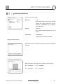
Motion Setup
MOTION SETUP
-----------------------MOTION LOCK
OFF
PWR UP ACTION
ON
AUTO FLIP
ON
JOG MAX SPEED
120/SEC
JOG DIRECTION
INVERSE
FRZ IN PRESET
OFF
<PARKING ACTION SETUP>
<ALARM INPUT SETUP>
BACK
EXIT
Setup the general functions of Pan/Tilt motions.
z Motion Lock
[ON/OFF]
If Motion Lock is set to ON, it is impossible to
set up and delete Preset, Swing, Pattern and
Group. It is only possible to run these
functions. To set
up and
delete these
functions, enter into OSD menu.
z Power Up Action
[ON/OFF]
Refer to “Other Functions" section.
z Auto Flip
[ON/OFF]
Refer to “Other Functions" section.
z Jog Max Speed
[1°/sec ~360°/sec]
Sets maximum jog speed. Jog speed is
inversely proportional to zoom magnification.
As zoom magnification goes up, pan/tilt
speed goes down.
z Jog Direction
[INVERSE/NORMAL]
If you set this to ‘Inverse’, the view on the
screen will move in the same direction as jog
tilt. If ‘Normal’ is selected, the view on the
screen will move in the opposite direction.
z Freeze in Preset
[ON/OFF]
At start point of preset movement, camera will
freeze the image of start point. Camera keeps
displaying the image of start point during
preset movement and does not display the
images received during preset movement. As
soon as camera stops at preset end point,
camera will display live images received at
the preset end point.
Availability of this function will vary by
model.
Speed Dome Camera Instruction Manual
30
HOW TO USE OSD MENU
4
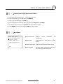
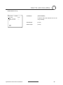
Parking Action Setup
PARKING ACTION SETUP
-----------------------PARK ENABLE
OFF
WAIT TIME
00:10:00
PARK ACTION
HOME
If Park Enable is set to ON, camera runs assigned function automatically
if there is no PTZ command during assigned "Wait Time".
z Park Enable
[ON/OFF]
z Wait Time
[1~10/15/30 seconds & 1/2/3/4 minutes]
The time is displayed with "hh:mm:ss" format
BACK
EXIT
and can be changed in 1 min units.
z Park Action
[HOME/PRESET/PATTERN/SWING/GROUP]
{ HOME
Camera moves to home position if there is no
PTZ command during assigned "Wait Time".
Alarm Input Setup
ALARM INPUT SETUP
-----------------------ALARM1 TYPE
N.OPEN
ALARM2 TYPE
N.OPEN
ALARM3 TYPE
N.OPEN
ALARM4 TYPE
N.OPEN
ALARM1 ACT
NOT USED
ALARM2 ACT
NOT USED
ALARM3 ACT
NOT USED
ALARM4 ACT
NOT USED
BACK
EXIT
Matches the Alarm sensor input to one of Preset positions. If an external
sensor is activated, camera will move to corresponding preset position
when this item is predefined.
z Alarm × Type
[Normal OPEN/Normal CLOSE]
Sets sensor input type.
z Alarm × Action
[NOT USED/PRESET 1~128]
Assign counteraction Preset position to each
Alarm input.
Speed Dome Camera Instruction Manual
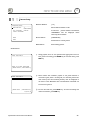
31
HOW TO USE OSD MENU
4
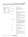
Preset Setup
PRESET SETUP
-----------------------PRESET NO.
1
CLR PRESET
<EDIT SCENE>
<EDIT LABEL>
CAM ADJUST
z Preset Number
[1~128]
If a selected preset is already defined, camera
moves to pre-defined position and preset
CANCEL
characteristics such as Label and Relay Outputs
LABEL123
GLOBAL
show on monitor. If a selected preset is not
defined, “UNDEFINED” shows on monitor.
BACK
EXIT
z Clear Preset
[CANCEL/OK]
Delete current Preset data
z Edit Preset Scene
Redefine current Preset scene position (i.e.
PTZ).
Edit Preset Scene
EDIT SCENE - PRESET 1
------------------------
○1 Using Joystick, move camera to desired position.
○2 By pressing NEAR key, save current PTZ data.
○3 Press FAR key to cancel.
MOVE TO TARGET POSITION
[NEAR:SAVE
/FAR:CANCEL]
Speed Dome Camera Instruction Manual
32
4
HOW TO USE OSD MENU
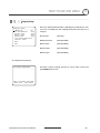
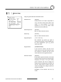
Swing Setup
SWING SETUP
-----------------------SWING NO.
1
1ST POS.
NOT USED
2ND POS.
NOT USED
SWING SPEED
CLEAR SWING
30/SEC
CANCEL
BACK
EXIT
z Swing Number
[1~8]
Select Swing number to edit. If a selected Swing is
not defined, "NOT USED" is displayed in 1st
Position and 2nd Position
z 1st Position
2nd Position
[PRESET 1~128]
Set up the 2 position for Swing function. If a
selected preset is not defined, "UNDEFINED" will
be displayed as shown below.
SWING SETUP
-----------------------SWING NO.
1
1ST POS.
PRESET5
2ND POS.
NOT USED
UNDEFINED
When swing function runs, the camera will move
from the preset assigned as the 1st point to the
preset assigned as the 2nd point in a CW
(Clockwise) direction. Then the camera will move
from the preset assigned as the 2nd point to the
preset assigned as the 1st point in a CCW
(Counterclockwise)
direction.
If
the
preset
assigned as the 1st point is same as the preset
assigned as the 2nd point, the camera will turn
360° in CW direction and then turn 360° in CCW
direction.
z Swing Speed
[1°/sec ~180°/sec]
Sets Swing speed from 1°/sec to 180°/sec.
z Clear Swing
[CANCEL/OK]
Deletes current Swing data.
Speed Dome Camera Instruction Manual
33
HOW TO USE OSD MENU
4
Pattern Setup
PATTERN SETUP
-----------------------PATTERN NO.
1
UNDEFINED
CLR PATTERN
CANCEL
<EDIT PATTERN>
z Pattern Number
[1~4 ]
Selects Pattern number to edit.
If a selected
"UNDEFINED"
pattern number is not defined,
will
be
displayed
under
selected pattern number.
z Clear Pattern
BACK
EXIT
[CANCEL/OK]
Deletes data in current pattern
z Edit Pattern
Starts editing pattern.
Edit Pattern
EDIT PATTERN 1
------------------------
①
Using Joystick, move to start position with appropriate zoom. To
start pattern recording, press NEAR key. To exit this menu, press
FAR key.
MOVE TO START POSITION
[NEAR:START /FAR:CANCEL]
②
EDIT PATTERN 1
Move camera with controller joystick or run preset function to
memorize a path (often a curved path) in a selected pattern. The
total memory size and remaining memory size are displayed in
the form of a bar. Maximum 1200 communication commands can
be stored in a pattern.
[NEAR:SAVE
/FAR:DELETE]
0/0/x1/N
Speed Dome Camera Instruction Manual
③ To save data and exit, press NEAR key. To cancel recording and
delete record data, press FAR key.
34
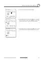
HOW TO USE OSD MENU
4
Group Setup
GROUP SETUP
-----------------------GROUP NO.
1
UNDEFINED
CLEAR GROUP
CANCEL
<EDIT GROUP>
z Group Number
[1~8]
Selects Group number to edit.
If a selected
Group number is not defined,
"UNDEFINED" will be displayed under selected
Group number.
BACK
EXIT
z Clear Group
[CANCEL/OK]
Deletes data in current Group
z Edit Group
Starts editing Group.
그룹 편집
EDIT GROUP 1
-----------------------NO ACTION ### DWELL OPT
-----------------------1 NONE
2 NONE
3 NONE
4 NONE
5 NONE
-----------------------SAVE
CANCEL
[NEAR:EDIT]
EDIT GROUP 1
-----------------------NO ACTION ### DWELL OPT
-----------------------1 NONE
2 NONE
3 NONE
4 NONE
5 NONE
-----------------------SAVE
[NEAR:EDIT ACT]
CANCEL
[FAR :EDIT END]
①
“Press Near key in “NO” list to start Group setup.
②
Note that MAX. 20 Functions are allowed in a Group. Move cursor
up/down and press Near key to set up.
③
Set up Action, Dwell time and Option. Note that selected item is
displayed in reverse. Move cursor Left/Right to select items and
move cursor Up/Down to change each value.
z Action ###
[NONE/PRESET/SWING/PATTERN]
z DWELL
[0 second ~ 4 minutes]
Sets Dwell Time between functions
z OPT
Option. Displays the preset speed when
preset is set in Action. Displays the number
of repeats when Pattern or Swing is selected
in Action
Speed Dome Camera Instruction Manual
35
HOW TO USE OSD MENU
EDIT GROUP 1
-----------------------NO ACTION ### DWELL OPT
-----------------------1 PRESET
1 00:03 360
2 NONE
3 NONE
4 NONE
5 NONE
-----------------------SAVE
[
:MOVE CURSOR]
CANCEL [
:CHANGE VAL.]
EDIT GROUP 1
-----------------------NO ACTION ### DWELL OPT
-----------------------1 PRESET
1 00:03 360
2 NONE
3 NONE
4 NONE
5 NONE
-----------------------SAVE
[NEAR:EDIT ACT]
CANCEL
[FAR :EDIT END]
EDIT GROUP 1
-----------------------NO ACTION ### DWELL OPT
-----------------------1 PRESET
1 00:03 360
2 NONE
3 NONE
4 NONE
5 NONE
-----------------------SAVE
CANCEL
Speed Dome Camera Instruction Manual
4
④
Set up items such as Action, ###, Dwell and OPT.
⑤
After finishing setup of an Action, press Near key to one-upperlevel menu (Step ②). Move cursor Up/Down to select Action
number and repeat Step ② ~ Step ④ to edit selected Group.
⑥ After finishing setup of all Actions, press FAR key to exit. Then
cursor should be moved to “SAVE”. Press Near key to save data.
36
HOW TO USE OSD MENU
4
System Initialize
SYSTEM INITIALIZE
-----------------------CLEAR ALL DATA
NO
CLR DISPLAY SET
NO
CLR CAMERA SET
NO
CLR MOTION SET
NO
CLR EDIT DATA
NO
REBOOT CAMERA
NO
REBOOT SYSTEM
NO
BACK
EXIT
z Clear All Data
Deletes all configuration data, such as display,
camera, and motion setup.
z Clear Display Set
Initializes Display Configuration
z Clear Camera Set
Initializes Camera Configuration
z Clear Motion Set
Initializes Motion Configuration
Deletes Preset Data, Swing Data, Pattern Data
z Clear Edit Data
and Group Data
z Reboot Camera
Reboots Zoom Camera module
z Reboot System
Reboots Speed Dome Camera
Initial Configuration Table
z Display Configuration
z Camera Configuration
Camera ID
ON
Focus Mode
SemiAuto
PTZ Information
AUTO
Digital Zoom
ON
Action Title
AUTO
Line Lock
OFF
Preset Label
AUTO
White Balance
AUTO
Alarm Input
AUTO
Backlight
OFF
North Direction
Pan 0°
Day&Night
AUTO2
Privacy Zone
Undefined
Brightness
25
Iris
AUTO
Shutter
ESC
z Motion Configuration
AGC
HIGH
Motion Lock
OFF
SSNR
MIDDLE
Power Up Action
ON
SENS-UP
AUTO
Auto Flip
ON
Jog Max Speed
120°/sec
z User Edit Data
Jog Direction
INVERSE
Preset 1~128
Undefined
Freeze In Preset
OFF
Swing 1~8
Undefined
Park Action
OFF
Pattern 1~4
Undefined
Alarm Action
OFF
Group 1~8
Undefined
Speed Dome Camera Instruction Manual
37
SPECIFICATIONS
5
Specifications
Video Signal System
NTSC
CCD
PAL
1/4'' Interline Transfer CCD
Max. Pixels
811(H)×508(V) 410K
795(H)×596(V) 470K
Effective Pixels
768(H)×494(V) 380K
752(H)×582(V) 440K
Horizontal Res.
500 TVL (Color), 570 TVL (B/W)
S/N Ratio
50 dB (AGC Off)
×10 Optical Zoom, ×10 Digital Zoom
Zoom
Camera
Focal length
F1.8, f=3.8~38mm
Min.
illumination
0.7 Lux (Color) / 0. 02 Lux (B/W), 50 IRE
Day & Night
Auto / Day / Night(ICR)
Focus
Auto / Manual
Shutter Speed
x128 ~ 1/120000 sec
AGC
White Balance
Normal / High / Off
Auto / Manual(Red, Blue Gain Adjustable)
BLC
Low / Middle / High / Off
Flickerless
Selectable
SSNR
Range
Pan/Tilt Speed
Pan/Tilt
Low / Middle / High / Off
Pan :
360°(Endless)
Tilt :
180° (Auto-Flip), 95° (Normal)
Preset :
360°/sec
Manual
:
0.05 ~ 360°/sec (proportional to zoom)
Swing :
1~ 180°/sec
Ceiling
Preset
127 Preset (Label, Camera Image Setting)
Pattern
4 Pattern, 1200 commands(about 5 minute)/Pattern
Swing
8 Swing
Group
8 Group (20 action entities per Group)
Other Functions
Auto Flip, Auto Parking, Power Up Action etc.
Communication
RS-485
Protocol
Pelco-D, Pelco-P selectable
Privacy Zone
4 Zone
Alarm Input
4 Input
OSD
Rated Power**
Menu / PTZ information etc
DC Type :
DC 12V / 0.8A , *DC 12V / 2.5A
AC Type :
AC 24V / 0.4A , *AC 24V / 1.5A
Dome :
Dimension
Ceiling
Housing
Weight
Operating
Temp.
IEC-529
Standard
Main Unit
Auto / Manual / SemiAuto
Iris
General
Appearance*
×10
Model
Main Unit
Ceiling
Wall
Wall
∅115
∅178× 233(H) mm
∅154.5 × 158.5(H) mm , *∅178
× 244(H)×289(H) mm
Approx. about 1.3 Kg, *1.9 Kg
Approx. *2.2Kg
Approx. *2.5Kg
0°C ~ 40°C , (*-30 ~ 50°C / -22~ 122°F)
*IP66
* PT110N-XT Model Only
** Check the voltage and current capacity of rated power carefully.
*** Specifications of this product are subject to change without notice.
Speed Dome Camera Instruction Manual
Sun shield
Note: PT110N-XT.
PT110N appearance will vary, see
page 38 for PT110N appearance specifications.
38
SPECIFICATIONS
5
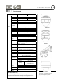
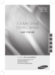
Dimensions-PT110N Indoor Model
z Main Unit & Surface Mount Bracket
z Ceiling Mount Bracket
z Wall Mount Bracket
Unit: mm
U
Speed Dome Camera Instruction Manual
39
SPECIFICATIONS
5
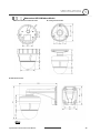
Dimensions-PT110N-XT Outdoor Model
z Ceiling Mount Bracket
z Sun shield
z Wall Mount Bracket
Unit: mm
Speed Dome Camera Instruction Manual
40
NOTES:
Speed Dome Camera Instruction Manual
41