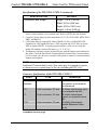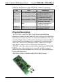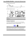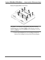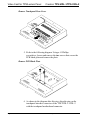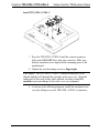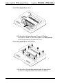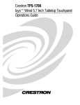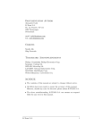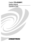
1
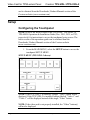
Crestron TPS-VIDL-1/TPS-VIDL-2 Video Card for TPS/Lectern Panel Operations & Installation Guide This document was prepared and written by the Technical Documentation department at: Crestron Electronics, Inc. 15 Volvo Drive Rockleigh, NJ 07647 1-888-CRESTRON All brand names, product names and trademarks are the property of their respective owners. ©2002 Crestron Electronics, Inc. Crestron TPS-VIDL-1/TPS-VIDL-2 Video Card for TPS/Lectern Panel Contents Video Card for TPS/Lectern Panel: TPS-VIDL-1/TPS-VIDL-2 1 Introduction......................................................................................1 Features and Functions ..........................................................1 Specifications.........................................................................2 Physical Description ..............................................................4 Industry Compliance..............................................................5 Installation and Hookup...................................................................6 Setup...............................................................................................12 Configuring the Touchpanel................................................12 VT Pro-e Setup ....................................................................14 SIMPL Windows Setup .......................................................15 Problem Solving.............................................................................16 Troubleshooting...................................................................16 Further Inquiries ..................................................................17 Future Updates.....................................................................17 Return and Warranty Policies ........................................................18 Merchandise Returns / Repair Service ................................18 CRESTRON Limited Warranty ..........................................18 Operations & Installation Guide - DOC. 6070 Contents • i Crestron TPS-VIDL-1/TPS-VIDL-2 Video Card for TPS/Lectern Panel Video Card for TPS/Lectern Panel: TPS-VIDL-1/TPS-VIDL-2 Introduction Features and Functions The TPS-VIDL-1 and TPS-VIDL-2 video cards are designed for Crestron’s Isys TPS-4500L, TPS-5000L, and TPS-6000L lectern/wall mounted touchpanels as well as the TPS-TPI Touchpanel Interface. Each card contains a video digitizer that allows video signals to be displayed on a touchpanel. The TPS-VIDL-1 can display one S-video or composite video source while the TPS-VIDL-2 can display one S-Video source or two composite video sources. The video card can accept either National Television System Committee (NTSC) or Phase Alternating Line (PAL) signal types. Composite and S-Video formats are supported and can be displayed in a window or full screen page in an uploaded Crestron VisionTools Pro-e (VT Pro-e) touchpanel project. Functional Summary • Built-in Time-Based Correction for Stable Video & Graphics • Scale video at full screen or window to any size • Display picture-in-picture or place windows anywhere on the screen • Supports NTSC/PAL Formats with Auto-Detect • Coaxial or Balanced Video Input • Auto-Detects Composite or S-Video Format within two seconds (TPS-VIDL-2 Auto-Detects format only on input 1 when input 2 is not used.) • Simultaneous display of two real-time video windows on one touchpanel screen (TPS-VIDL-2 only) • TPS touchpanels can display up to three sources on-screen simultaneously when TPS-VIDL-2 and TPS-XVGAL cards are installed (two composite video, one VGA) Operations & Installation Guide - DOC. 6070 Video Card for TPS/Lectern Panel: TPS-VIDL-1/TPS-VIDL-2 • 1 Video Card for TPS/Lectern Panel Crestron TPS-VIDL-1/TPS-VIDL-2 The TPS-VIDL-1 can automatically detect composite or S-video. The TPS-VIDL-2 adds input for a second composite video source (on the TPS-VIDL-2, Composite/S-Video can be auto-detected only when input signal 2 is not used). When using the TPS-VIDL-2 for receiving two video sources, the “Comp/Y” connection will be used for Composite Video Source 1 while the chroma (C) connection will be used for Composite Video Source 2. Specifications The table below provides a summary of specifications for the TPS-VIDL-1 and TPS-VIDL-2 cards. Specifications of the TPS-VIDL-1/VIDL-2 SPECIFICATION Power Requirements Control System Update Files1,2,3 2-Series Control System CEN/CN-TVAV CNMSX-AV/PRO CNRACKX/-DP ST-CP Isys™ Touchpanel Firmware4 VT Pro-e Programming Software1 Video Types Video Formats Video Format Detection Operating Temperature and Humidity DETAILS TPS-VIDL-1: 7 Watts (0.29 Amp @ 24 VDC) TPS-VIDL-2: 12 Watts (0.50 Amp @ 24 VDC) Version C2-2004.CUZ or later Version 5.12.63v.UPZ or later Version 5.12.63x.UPZ or later Version 5.12.63w.UPZ or later Version 4.02.4S.UPZ or later Version 1.018 or later Version 3.0.0.8 or later NTSC or PAL Composite or S-Video Within 2 seconds 50º to 113º F (10º to 45º C), 10 to 90% Relative Humidity (noncondensing) (continued on next page) 2 • Video Card for TPS/Lectern Panel: TPS-VIDL-1/TPS-VIDL-2 Operations & Installation Guide - DOC. 6070 Crestron TPS-VIDL-1/TPS-VIDL-2 Video Card for TPS/Lectern Panel Specifications of the TPS-VIDL-1/VIDL-2 (continued) SPECIFICATION Dimensions and Weight DETAILS Height: 1.16 in (2.95 cm) Width: 2.63 in (6.68 cm) Depth: 6.50 in (16.51 cm) Weight: 1.60 oz (0.05 kg) 1. The latest versions can be obtained from the Downloads | Software Updates section of the Crestron website (www.crestron.com). Refer to NOTE after last footnote. 2. Crestron 2-Series control systems include the AV2, CP2, CP2E, MP2, MP2E, PAC2, PRO2, and RACK2. 3. CNX update files are required for either CNMSX-AV/Pro or CNRACKX/-DP. Filenames for CNX update files have a UPZ extension and ST-CP files are in one EXE or zipped UPZ file. To avoid program problems, verify you are using the update file with the correct suffix letter (e.g., S, V, W, X). 4. Touchpanels with later versions of firmware may include features not mentioned in this guide. Check the Downloads | Product Manuals section of the Crestron website (www.crestron.com) for newer versions of this guide or contact a Crestron technical support representative. NOTE: Crestron software and any files on the website are for Authorized Crestron dealers only. New users may be required to register to obtain access to certain areas of the site (including the FTP site). Connector Specifications of the TPS-VIDL-1/VIDL-2 PORT TYPE Touchpanel Interface 60 pin connector C+ 6-pin connector, 3.5 mm C- 6-pin connector, 3.5 mm CS 6-pin connector, 3.5 mm SIGNAL(S) Various. Provides connection to touchpanel motherboard S-Video chrominance input or composite input #2 S-Video chrominance return or composite return #2 S-Video chrominance shield (Balanced Video only) (continued on next page) Operations & Installation Guide - DOC. 6070 Video Card for TPS/Lectern Panel: TPS-VIDL-1/TPS-VIDL-2 • 3 Video Card for TPS/Lectern Panel Crestron TPS-VIDL-1/TPS-VIDL-2 Connector Specifications of the TPS-VIDL-1/VIDL-2 (continued) PORT TYPE SIGNAL(S) Y+ 6-pin connector, 3.5 mm Y- 6-pin connector, 3.5 mm YS 6-pin connector, 3.5 mm C BNC COMP / Y BNC S-Video luminance input or composite input #1 S-Video luminance return or composite return #1 S-Video luminance shield (Balanced Video only) S-video chrominance or composite input #2 S-Video luminance or composite input #1 Physical Description The TPS-VIDL-1 and TPS-VIDL-2 card, shown in the following diagrams, is a printed circuit board (PCB) that is designed for installation into a dedicated expansion slot on the touchpanel motherboard. The card contains a 60-pin connector that attaches directly to the motherboard and is secured with four mounting screws (supplied with each model of the video card). Video access is through two BNC connectors or a 6-pin mini-phoenix connector that are permanently attached to the TPS-VIDL card. The connectors (individually labeled in the NTSC/PAL INPUT section of the touchpanel) are accessible from the connector panel at the rear of the touchpanel case. Refer to the following diagrams for physical dimensions. TPS-VIDL-1/VIDL-2 VIDEO CARD (TPS-VIDL-2 Shown) 4 • Video Card for TPS/Lectern Panel: TPS-VIDL-1/TPS-VIDL-2 Operations & Installation Guide - DOC. 6070 Crestron TPS-VIDL-1/TPS-VIDL-2 Video Card for TPS/Lectern Panel TPS-VIDL-1/VIDL-2 Side View 0.73 in (1.85 cm) 1.16 in (2.95 cm) TPS-VIDL-1/VIDL-2 Top View 6.50 in (16.51 cm) 2.63 in (6.67 cm) NOTE: The TPS-VIDL-1 circuit board is slightly less populated than the TPS-VIDL-2. Industry Compliance As of the date of manufacture, the card has been tested and found to comply with specifications for CE marking and standards per EMC and Radiocommunications Compliance Labelling (N11785). NOTE: This device complies with part 15 of the FCC rules. Operation is subject to the following two conditions: (1) this device may not cause harmful interference, and (2) this device must accept any interference received, including interference that may cause undesired operation. Operations & Installation Guide - DOC. 6070 Video Card for TPS/Lectern Panel: TPS-VIDL-1/TPS-VIDL-2 • 5 Video Card for TPS/Lectern Panel Crestron TPS-VIDL-1/TPS-VIDL-2 Installation and Hookup The TPS-VIDL-1 and TPS-VIDL-2 video cards are designed for installation into a dedicated expansion slot on the TPS touchpanel. The only tools required for installation are a #1 Phillips screwdriver and a grounding strap (or grounded workstation). CAUTION: The TPS-VIDL-1, TPS-VIDL-2, and the touchpanel contain electro-static discharge (ESD) sensitive devices. Perform the following procedures while wearing a grounding strap that is properly grounded and on a grounded workstation to avoid damaging the TPS-VIDL card and/or the touchpanel. CAUTION: To prevent stripping of screw heads, threads, or mounting holes, DO NOT overtighten screws. Tighten only to the specification listed in the individual step(s). NOTE: The diagrams in this procedure show a TPS-6000L touchpanel but the steps for the TPS-4500L, TPS-5000L and TPS-TPI are identical. This procedure pertains to a touchpanel or interface that is NOT installed into a wall or lectern. If already installed, refer to the latest revision of the TPS-4500L, TPS-5000L, TPS-6000L, or TPS-TPI Operations & Installation Guide (Doc. 5891, 5825, 5783, or 5855, respectively) or, if applicable, BB-5000 or BB-6000 Installation Guide (Doc. 5826 or 5827) for instructions on removing the touchpanel. The latest versions of operations guides can be obtained from the Downloads | Product Manuals section of the Crestron website (www.crestron.com). 1. To prevent errors when re-connecting, label each cable attached to the touchpanel’s rear ports before disconnecting. 2. To prevent scratching of the screen (TPS-TPI excluded), place the touchpanel facedown onto a padded surface. 3. Refer to the following diagram. Using a #1 Phillips screwdriver, loosen and remove the 10 screws that secure the touchpanel rear cover. 6 • Video Card for TPS/Lectern Panel: TPS-VIDL-1/TPS-VIDL-2 Operations & Installation Guide - DOC. 6070 Crestron TPS-VIDL-1/TPS-VIDL-2 Video Card for TPS/Lectern Panel Remove Touchpanel Rear Cover Screws CAUTION: The connectors of any optional cards that are already installed may have to be aligned slightly to allow the rear cover to be removed. Align the connectors carefully to prevent damage to the card, cover, or touchpanel. 4. Remove the touchpanel rear cover by sliding it towards the bottom of the touchpanel as shown in the following diagram. Operations & Installation Guide - DOC. 6070 Video Card for TPS/Lectern Panel: TPS-VIDL-1/TPS-VIDL-2 • 7 Video Card for TPS/Lectern Panel Crestron TPS-VIDL-1/TPS-VIDL-2 Remove Touchpanel Rear Cover 5. Refer to the following diagram. Using a #1 Phillips screwdriver, loosen and remove the two screws that secure the PCB blank plate and remove the plate. Remove PCB Blank Plate 6. As shown in the diagram after this step, align the pins on the touchpanel interface connector of the TPS-VIDL-1/VIDL-2 with the touchpanel motherboard connector. 8 • Video Card for TPS/Lectern Panel: TPS-VIDL-1/TPS-VIDL-2 Operations & Installation Guide - DOC. 6070 Crestron TPS-VIDL-1/TPS-VIDL-2 Video Card for TPS/Lectern Panel Install TPS-VIDL-1/VIDL-2 7. Press the TPS-VIDL-1/VIDL-2 until the connector pins are fully seated. DO NOT force pins into connector. Make sure that the mounted screws align with the mounting posts of the motherboard. 8. Tighten the card mounting screws to finger-tight. CAUTION: The TPS-VIDL-2/VIDL-2 connectors may have to be aligned slightly to fit through the openings in the rear cover. Align the connectors of this card (or any other optional card that is installed) carefully to prevent damage to the card, cover, or touchpanel. 9. As shown in the following diagram, install the touchpanel rear cover by sliding it over the TPS-VIDL-1/VIDL-2 connectors. Operations & Installation Guide - DOC. 6070 Video Card for TPS/Lectern Panel: TPS-VIDL-1/TPS-VIDL-2 • 9 Video Card for TPS/Lectern Panel Crestron TPS-VIDL-1/TPS-VIDL-2 Install Touchpanel Rear Cover 10. Refer to the following diagram. Using a #1 Phillips screwdriver, install 10 screws and tighten to 4-inch pounds (0.45 Newton-meters) to secure the cover. Install Touchpanel Rear Cover Screws 11. Refer to the following diagram and make the appropriate S-video or composite video connection(s) as shown. 10 • Video Card for TPS/Lectern Panel: TPS-VIDL-1/TPS-VIDL-2 Operations & Installation Guide - DOC. 6070 Crestron TPS-VIDL-1/TPS-VIDL-2 Video Card for TPS/Lectern Panel Attach Appropriate Video Cables NTSC/PAL INPUT C Y + - S + - S S-VIDEO CHROMINANCE OR COMPOSITE INPUT #2 S-VIDEO LUMINANCE OR COMPOSITE VIDEO INPUT #1 C COMP Y S-VIDEO CHROMINANCE OR COMPOSITE INPUT #2 S-VIDEO LUMINANCE OR COMPOSITE VIDEO INPUT #1 ON TPS-VIDL-2, USE "COMP/Y" FOR SIGNAL 1 AND "C" FOR SIGNAL 2 NOTE: When using the TPS-VIDL-2 for receiving two video sources, the “Comp/Y” connection will be used for Video Source 1 while the chroma (C) connection will be used for Video Source 2. NOTE: Up to four composite video feeds can be physically connected to a TPS-VIDL-2 (two BNC feeds and two twisted-pair feeds). However, only two video channels can be selected for viewing from the touchpanel setup screen. Refer to “Configuring the Touchpanel” on page 12 for more information. NOTE: For additional information on video connections over CAT5, refer to the latest version of the Crestron CAT5 Wiring Reference Guide (Doc. 6137) which is available from the Downloads | Product Manuals section of the Crestron website (www.crestron.com). 12. Reconnect all appropriate cables and install the touchpanel into the wall or lectern. NOTE: Refer to the latest revision of the TPS-4500L, TPS-5000L, TPS-6000L, or TPS-TPI Operations & Installation Guide (Doc. 5891, 5825, 5783, or 5855, respectively) or, if applicable, BB-5000 or BB-6000 Installation Guide (Doc. 5826 or 5827) for the proper installation procedure of the touchpanel. The latest version of the Operations Guide Operations & Installation Guide - DOC. 6070 Video Card for TPS/Lectern Panel: TPS-VIDL-1/TPS-VIDL-2 • 11 Video Card for TPS/Lectern Panel Crestron TPS-VIDL-1/TPS-VIDL-2 can be obtained from the Downloads | Product Manuals section of the Crestron website (www.crestron.com). Setup Configuring the Touchpanel NOTE: Refer to the latest revision of the TPS-4500L, TPS-5000L, or TPS-6000L Operations & Installation Guide (Doc. 5891, 5825, or 5783, respectively) for instructions to access the touchpanel setup screen. The latest version of the operations guide can be obtained from the Downloads | Product Manuals section of the Crestron website (www.crestron.com). 1. From the MAIN MENU, select the SETUP button to access the touchpanel SETUP MENU. SETUP MENU (TPS-VIDL-1 shown) NOTE: If the TPS-VIDL-1 is installed, a single “Video” button will be displayed. If the TPS-VIDL-2 is installed, buttons labeled “Video 1” and “Video 2” will be displayed instead of the single “Video” button. NOTE: If the video card is not properly installed, the “Video” button(s) will not be displayed. 12 • Video Card for TPS/Lectern Panel: TPS-VIDL-1/TPS-VIDL-2 Operations & Installation Guide - DOC. 6070 Crestron TPS-VIDL-1/TPS-VIDL-2 Video Card for TPS/Lectern Panel 2. Select the Video button from the SETUP MENU to set preferences for the video source. If a TPS-VIDL-2 is installed, buttons labeled “Video 1” and “Video 2” will be displayed instead of the single Video button. Select the appropriate “Video” button to set preference for the video source. Video Setup 3. The twisted-pair and BNC inputs can be configured to autodetect the signal type (S-Video or Composite) or can be set to a specific signal type. Select the appropriate signal type. NOTE: When configuring the TPS-VIDL-2, the Video 1 signal type can be automatically detected as long as one signal is sent to the touchpanel. NOTE: Up to four composite video feeds can be physically connected to a TPS-VIDL-2 (two BNC feeds and two twisted-pair feeds). However, only two composite video channels can be selected for viewing. Specify the connections to use by selecting TP composite, TP S-Video, BNC Composite, or BNC S-Video for each channel. NOTE: A solid blue screen is displayed in the video window if a video signal is not detected or is very weak. Verify that the video source is functioning and properly connected. If the source is properly connected and functioning, a distribution amplifier may need to be used. Operations & Installation Guide - DOC. 6070 Video Card for TPS/Lectern Panel: TPS-VIDL-1/TPS-VIDL-2 • 13 Video Card for TPS/Lectern Panel Crestron TPS-VIDL-1/TPS-VIDL-2 4. Select the preferences for the video signals appearance. Refer to the following table for further information. Video Setup Details VIDEO SCREEN BUTTONS Brightness Contrast Saturation Hue Fast Motion / Still Video (toggle) Soft / Sharp (toggle) Default Return DESCRIPTION Use to increase or decrease image brightness. Use to increase or decrease image contrast. Use to increase or decrease image saturation. Use to shift the color balance. The Fast Motion setting eliminates motion artifacts caused by the difference between the first and second halves of a video field and softens the image. The Still Video setting yields a much sharper image, however, motion artifacts may occur if fast moving objects are displayed. Used to soften images that are too sharp or sharpen video images that are too soft. Returns you to the default settings*. Saves the settings and returns to the SETUP MENU * Video default is 50% for each of the video parameters (brightness, contrast, saturation, and hue) fast motion, sharp picture, and Composite Video on BNC connector 5. Select the Return button to save settings and return to the SETUP MENU. VT Pro-e Setup A video window object must reside on a page within the uploaded VT Pro-e touchpanel project and the TPS-VIDL-1 or TPS-VIDL-2 must be properly installed into the touchpanel in order for video signals to be displayed. When using the TPS-VIDL-2, the video window object properties must have the video source specified in the Input number field (“Composite 1” 14 • Video Card for TPS/Lectern Panel: TPS-VIDL-1/TPS-VIDL-2 Operations & Installation Guide - DOC. 6070 Crestron TPS-VIDL-1/TPS-VIDL-2 Video Card for TPS/Lectern Panel for Video 1 or “Composite 2” for Video 2) of the Source tab. Refer to the following illustration that shows selection of the video source. Selecting the Video Source NOTE: If the card is not present, the Crestron Viewport displays a warning message during the upload and the video window remains blank. For further information regarding video window objects, refer to the VT Pro-e help file. SIMPL Windows Setup The touchpanel does not require special programming in SIMPL Windows to display video. Operations & Installation Guide - DOC. 6070 Video Card for TPS/Lectern Panel: TPS-VIDL-1/TPS-VIDL-2 • 15 Video Card for TPS/Lectern Panel Crestron TPS-VIDL-1/TPS-VIDL-2 Problem Solving Troubleshooting The table below provides corrective action for possible trouble situations. If further assistance is required, please contact a Crestron customer service representative. TPS-VIDL-1/VIDL-2 Troubleshooting TROUBLE Video window touchpanel has no display. POSSIBLE CAUSE(S) CORRECTIVE ACTION Improper video connection. Incorrect video format selection. Incorrect firmware/software. Incorrect VT Pro-e project file loaded. TPS-VIDL-1/2 improperly installed. Damaged connector pins. Video colors are wrong and/or moving. Touchpanel is set to Auto-Detect or S-Video when two composite signals are plugged into the touchpanel. 16 • Video Card for TPS/Lectern Panel: TPS-VIDL-1/TPS-VIDL-2 Verify proper connections on the touchpanel. Select the proper video input configuration in the touchpanel configuration SETUP MENU. Update firmware/software versions as per “Specifications”. Make sure that video window object resides in project, re-compile, and reload. Follow installation procedures in this guide. Inspect connector pins. If bent, carefully re-straighten. If broken, contact Crestron customer service. Switch to “Composite” video. Operations & Installation Guide - DOC. 6070 Crestron TPS-VIDL-1/TPS-VIDL-2 Video Card for TPS/Lectern Panel Further Inquiries If after reviewing this Operations & Installations Guide, you cannot locate specific information or have questions, please take advantage of Crestron's award winning customer service team by calling: • In the US and Canada, call Crestron’s corporate headquarters at 1-888-CRESTRON [1-888-273-7876]. • In Europe, call Crestron International at +32-15-50-99-50. • In Asia, call Crestron Asia at +852-2341-2016. • In Latin America, call Crestron Latin America at +5255-5093-2160. • In Australia and New Zealand, call Crestron Control Solutions at +61-2-9737-8203. Future Updates As Crestron improves functions, adds new features, and extends the capabilities of the TPS-VIDL-1 or TPS-VIDL-2, additional information may be made available as manual updates. These updates are solely electronic and serve as intermediary supplements prior to the release of a complete technical documentation revision. Check the Crestron website (www.crestron.com) periodically for manual update availability and its relevance. Updates are available from the Downloads | Product Manuals section and are identified as an “Addendum” in the Download column. Operations & Installation Guide - DOC. 6070 Video Card for TPS/Lectern Panel: TPS-VIDL-1/TPS-VIDL-2 • 17 Video Card for TPS/Lectern Panel Crestron TPS-VIDL-1/TPS-VIDL-2 Return and Warranty Policies Merchandise Returns / Repair Service 1. No merchandise may be returned for credit, exchange, or service without prior authorization from CRESTRON. To obtain warranty service for CRESTRON products, contact the factory and request an RMA (Return Merchandise Authorization) number. Enclose a note specifying the nature of the problem, name and phone number of contact person, RMA number, and return address. 2. Products may be returned for credit, exchange, or service with a CRESTRON Return Merchandise Authorization (RMA) number. Authorized returns must be shipped freight prepaid to CRESTRON, 6 Volvo Drive, Rockleigh, N.J., or its authorized subsidiaries, with RMA number clearly marked on the outside of all cartons. Shipments arriving freight collect or without an RMA number shall be subject to refusal. CRESTRON reserves the right in its sole and absolute discretion to charge a 15% restocking fee, plus shipping costs, on any products returned with an RMA. 3. Return freight charges following repair of items under warranty shall be paid by CRESTRON, shipping by standard ground carrier. In the event repairs are found to be non-warranty, return freight costs shall be paid by the purchaser. CRESTRON Limited Warranty CRESTRON ELECTRONICS, Inc. warrants its products to be free from manufacturing defects in materials and workmanship under normal use for a period of three (3) years from the date of purchase from CRESTRON, with the following exceptions: disk drives and any other moving or rotating mechanical parts, pan/tilt heads and power supplies are covered for a period of one (1) year; touchscreen display and overlay components are covered for 90 days; batteries and incandescent lamps are not covered. This warranty extends to products purchased directly from CRESTRON or an authorized CRESTRON dealer. Purchasers should inquire of the dealer regarding the nature and extent of the dealer's warranty, if any. CRESTRON shall not be liable to honor the terms of this warranty if the product has been used in any application other than that for which it was intended, or if it has been subjected to misuse, accidental damage, modification, or improper installation procedures. Furthermore, this warranty does not cover any product that has had the serial number altered, defaced, or removed. This warranty shall be the sole and exclusive remedy to the original purchaser. In no event shall CRESTRON be liable for incidental or consequential damages of any kind (property or economic damages inclusive) arising from the sale or use of this equipment. CRESTRON is not liable for any claim made by a third party or made by the purchaser for a third party. CRESTRON shall, at its option, repair or replace any product found defective, without charge for parts or labor. Repaired or replaced equipment and parts supplied under this warranty shall be covered only by the unexpired portion of the warranty. Except as expressly set forth in this warranty, CRESTRON makes no other warranties, expressed or implied, nor authorizes any other party to offer any warranty, including any implied warranties of merchantability or fitness for a particular purpose. Any implied warranties that may be imposed by law are limited to the terms of this limited warranty. This warranty statement supercedes all previous warranties. Trademark Information All brand names, product names, and trademarks are the sole property of their respective owners. Windows is a registered trademark of Microsoft Corporation. Windows95/98/Me and WindowsNT/2000 are trademarks of Microsoft Corporation. 18 • Video Card for TPS/Lectern Panel: TPS-VIDL-1/TPS-VIDL-2 Operations & Installation Guide - DOC. 6070 Crestron TPS-VIDL-1/TPS-VIDL-2 Video Card for TPS/Lectern Panel This page intentionally left blank Operations & Installation Guide - DOC. 6070 Video Card for TPS/Lectern Panel: TPS-VIDL-1/TPS-VIDL-2 • 19 Crestron Electronics, Inc. Operations & Installation Guide - DOC. 6070 15 Volvo Drive Rockleigh, NJ 07647 12.02 Tel: 888.CRESTRON Fax: 201.767.7576 Specifications subject to www.crestron.com change without notice.