1
''(
Preface
Firmware Version 1.07
Thank you for choosing DELTA’s high-performance VFD-D D Series. The VFD-DD Series is
manufactured with high-quality components and materials and incorporate the latest microprocessor
technology available.
This manual is to be used for the installation, parameter setting, troubleshooting, and daily maintenance
of the AC motor drive. To guarantee safe operation of the equipment, read the following safety
guidelines before connecting power to the AC motor drive. Keep this operating manual at hand and
distribute to all users for reference.
To ensure the safety of operators and equipment, only qualified personnel familiar with AC motor drive
are to do installation, start-up and maintenance. Always read this manual thoroughly before using
VFD-M-D series AC Motor Drive, especially the WARNING, DANGER and CAUTION notes. Failure to
comply may result in personal injury and equipment damage. If you have any questions, please contact
your dealer.
PLEASE READ PRIOR TO INSTALLATION FOR SAFETY.
; AC input power must be disconnected before any wiring to the AC motor drive is
made.
DANGER
; A charge may still remain in the DC-link capacitors with hazardous voltages, when
the power is turned off.
; There are highly sensitive CMOS IC components on the printed circuit boards.
These components are especially sensitive to static electricity. To prevent damage
to these components, do not touch these components or the circuit boards with
metal objects or your bare hands.
; Ground the VFD-DD drive using the ground terminal. The grounding method must
comply with the local standard of the country which the drive is installed.
; VFD-DD series can only be used for variable speed control of 3-phase induction
motors, it should NOT be applied to 1-phase motors or other purpose.
; VFD-DD series is a specific drive for elevator door and other automatic door
control. It should not be installed in a location that may cause personal injury.
; To prevent personal injury, please keep children and unqualified people away from
the equipments.
; Do NOT connect AC main power directly to the drive’s output terminals U/T1, V/T2
and W/T3.
; DO NOT use Hi-pot test for internal components. The semi-conductor used in the
AC motor drive is easily damaged by high-pressure.
; A charge may still remain in the main circuit terminals with hazardous voltages,
even when motor has come to stop.
; Only the qualified technicians are allowed to install, wire and maintain AC motor
drive.
; Be aware of the motor that it may rotates as soon as the RUN key is pressed using
an external digital keypad, DO NOT stand next to the motor.
; DO NOT install the AC motor drive in a place subjected to high temperature, direct
sunlight, high humidity, excessive vibration, corrosive gases or liquids, or airborne
dust or metallic particles.
; Please regards the specification for AC motor drives installation. Failure to comply
may result in fire, explosion or electric shock.
; When the motor cable between the AC motor drive and motor is too long, the layer
insulation of the motor may be damaged.
; The rated voltage for the AC motor drive must be ≤ 240V and the mains supply
current capacity must be ≤ 5000A RMS.
; If the AC motor drive is stored in no charge condition for more than 3 months, the
ambient temperature should not be higher than 30 °C. Storage longer than one
year is not recommended, it could result in the degradation of the electrolytic
capacitors.
; Pay attention to the following when transporting and installing this package
(including wooden crate, wood stave and carton box)
1.
If you need to sterilize, deworm the wooden crate or carton box, please do
not use steamed smoking sterilization or you will damage the VFD.
2.
Please use other ways to sterilize or deworm.
3.
You may use high temperature to sterilize or deworm. Leave the packaging
materials in an environment of over 56℃ for 30 minutes.
4.
It is strictly forbidden to use steamed smoking sterilization.
The warranty
does not covered VFD damaged by steamed smoking sterilization.
NOTE
Some of the graphics shown in this manual are the inner part of the drive after the cover is removed, when VFD-DD is in
operation status, please make sure the cover and wiring are in the specified space as the manual indicates for personal
safety.
The drive customers received may be slightly different than the figures shown in the manual, this condition is normal and will
cause no influences to the customer rights.
Delta is always improving our products for greater efficiency; the content of this document may be modified or changed
without prior notice. Please contact your local distributors or visit our website to download the most updated version at
http://www.delta.com.tw/industrialautomation/.
The AC motor drive may also be called as “drive”, all drive mentioned in this manual refers to the AC motor drive.
Table of Content
Chapter 1 Introduction
1-1 Receiving and Inspection .................................................................................................... 1 - 2
1-2 Preparation for Installation and Wiring ............................................................................... 1 - 4
1-3 Dimensions ....................................................................................................................... 1 - 6
Chapter 2 Wiring
2-1 Wiring Diagram .................................................................................................................. 2 - 2
2-2 Main Circuit Terminal........................................................................................................... 2 - 6
2-3 Control Circuit Terminal ....................................................................................................... 2 - 8
Chapter 3 Keypad and Start-up
3-1 Operation Method ............................................................................................................... 3 - 2
3-2 Keypad Descriptions ........................................................................................................... 3 - 3
Chapter 4 Parameter Settings
4-1 Summary of Parameter Settings ......................................................................................... 4 - 2
Group 00: System Parameters ......................................................................................... 4 - 2
Group 01: Motor Parameters ............................................................................................ 4 - 4
Group 02 : Input/Output Parameters................................................................................. 4 - 6
Group 03: Feedback Parameters ..................................................................................... 4 - 8
Group 04: Door Open Parameters.................................................................................... 4 - 9
Group 05: Door Close Parameter .................................................................................... 4 -10
Group 06: Protection and Special Parameters................................................................. 4 -12
Group 07: Control Parameters......................................................................................... 4 -15
Group 08: Multi-step Speed Parameters........................................................................ 4 -16
Group 09: Communication Parameters ......................................................................... 4 -17
Group 10:User-defined Parameters............................................................................... 4 -18
Group 11:View User-defined Parameters ........................................................................ 4 -20
4-2 Summary of Detailed Parameter Settings .........................................................................4 -21
Group 00: System Parameters
.....................................................................................4 - 2 1
Group 01: Motor Parameters ...........................................................................................4 - 2 7
Group 02 : Input/Output Parameters................................................................................4 - 3 4
Group 03: Feedback Parameters ....................................................................................4 - 3 9
Group 04: Door Open Parameters .................................................................................. 4 - 4 2
Group 05: Door Close Parameter.................................................................................... 4 -46
Group 06: Protection and Special Parameters................................................................. 4 -51
Group 07: Control Parameters ........................................................................................ 4 -57
Group 08: Multi-step Speed Parameters ......................................................................... 4 -60
Group 09: Communication Parameters ........................................................................... 4 -61
Group 10: User-defined Parameters ............................................................................... 4 -71
Group 11: View User-defined Parameters ....................................................................... 4 -76
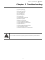
Chapter 5 Troubleshooting
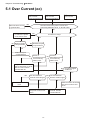
5-1 Over Current (OC) ......................................................................................................5 - 2
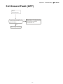
5-2 Ground Fault (GFF) ....................................................................................................5 - 3
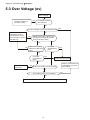
5-3 Over Voltage (OV).......................................................................................................5 - 4
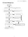
5-4 Low Voltage (Lv) .........................................................................................................5 - 5
5-5 Over Heat (OH1).........................................................................................................5 - 6
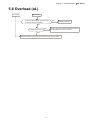
5-6 Overload (OL) .............................................................................................................5 - 7
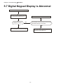
5-7 Digital Display is Abnormal..........................................................................................5 - 8
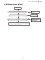
5-8 Phase Loss (PHL).......................................................................................................5 - 9
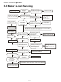
5-9 Motor is not Running................................................................................................. 5 - 1 0
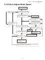
5-10 Fail to Adjust Motor Speed ...................................................................................... 5 - 11
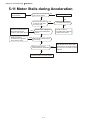
5-11 Motor Stalls During Acceleration.............................................................................. 5 - 1 2
5-12 Motor Run Error ...................................................................................................... 5 - 1 3
5-13 Electromagnetic/Induction Noise............................................................................. 5 - 1 4
5-14 Environmental Condition ......................................................................................... 5 - 1 5
5-15 Prevent Interference to other Devices ..................................................................... 5 - 1 6
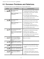
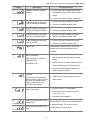
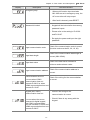
Chapter 6 Fault Codes and Descriptions
6-1 Common Problems and Solutions...............................................................................6 - 2
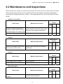
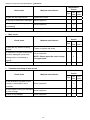
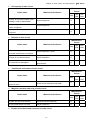
6-2 Maintenance and Inspectations...................................................................................6 - 7
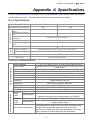
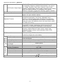
Appendix A Specifications ................................................................................................................. A -1
Appendix B How to Select AC Motor Drive........................................................................................ B -1
B-1 Capacity Formula .......................................................................................................B - 2
B-2 General Precautions...................................................................................................B - 4
B-3 How to Choose a Suitable Motor ................................................................................B - 5
Chapter 1 Introduction |DD Series
Chapter 1 Introduction
1-1 Receiving and Inspection
1-2 Preparation for Installation and Wiring
1-3 Dimensions
The AC motor drive should be kept in the shipping carton or crate before installation. In order to retain
the warranty coverage, the AC motor drive should be stored properly when it is not to be used for an
extended period of time. Storage conditions are:
; Store in a clean and dry location free from direct sunlight or corrosive fumes.
; Store within an ambient temperature range of -20 °C to +60 °C.
; Store within a relative humidity range of 0% to 90% and non-condensing
environment.
; Store within an air pressure range of 86 kPA to 106kPA.
; DO NOT place on the ground directly. It should be stored properly. Moreover, if the
surrounding environment is humid, you should put exsiccator in the package.
; DO NOT store in an area with rapid changes in temperature. It may cause
condensation and frost.
; If the AC motor drive is stored for more than 3 months, the temperature should not be
higher than 30 °C. Storage longer than one year is not recommended, it could result
in the degradation of the electrolytic capacitors.
; When the AC motor drive is not used for longer time after installation on building sites
or places with humidity and dust, it’s best to move the AC motor drive to an
environment as stated above.
1-1
Chapter 1 Introduction |DD Series
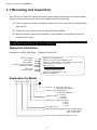
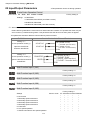
1-1 Receiving and Inspection
This VFD-VL AC motor drive has gone through rigorous quality control tests at the factory before
shipment. After receiving the AC motor drive, please check for the following:
; Check to make sure that the package includes an AC motor drive, the User Manual/Quick
Start and CD.
; Inspect the unit to assure it was not damaged during shipment.
; Make sure that the part number indicated on the nameplate corresponds with the part
number of your order.
If the nameplate information does not correspond with your purchase order or if there are
any problems, please contact your local distributor.
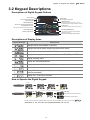
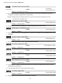
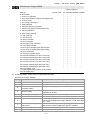
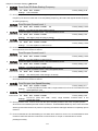
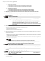
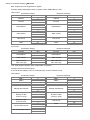
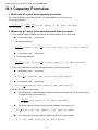
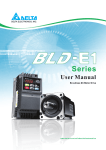
Nameplate Information
Example for 0.2kW/0.25HP 230V 1-Phase AC motor drive
AC Drive Model
Input Spec.
Output Spec.
Output Frequency Range
Software Version
Bar Code
Serial Number
MODEL: VFD002DD21A
INPUT: 1PH 200-240V 50/60Hz 4.9A
OUTPUT: 3PH 0-240V 1.5A 0.6kVA 0.2kW/0.25HP
FREQUENCY RANGE: 0.1-120Hz
Version: 01.00
02DD21A0T0330003
DELTA ELECTRONICS, INC.
MADE IN TAIWAN
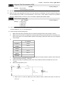
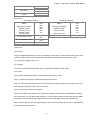
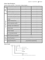
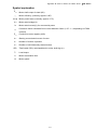
Explanation for Model
VFD 002 DD 2 1 A 5
Function B: with brake function
: without brake function
Version Type A: Standard
C: Built-in CANopen
E: economy
Voltage Phase 3: 3-Phase
1: 1-Phase
Mains Input Voltage 6: 696V
4: 460V
2: 230V
1: 115V
VFD- DD Series
Applicable Motor Capacity 002: 0.2kW 0.25HP
004: 0.4kW 0.5HP
007: 0.7kW 1HP
Series Name (Variable Frequency Drive)
1-2
Chapter 1 Introduction |DD Series
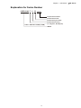
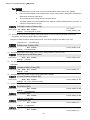
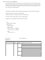
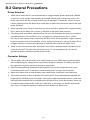
Explanation for Series Number
02DD21A0 T 0 33
230V 1-PHASE 0.25HP(0.2kW)
Production number
Production week
Production year 2007
Production factory
(T: Taoyuan, W: Wujian)
Model
1-3
Chapter 1 Introduction |DD Series
1-2 Preparation for Installation and Wiring
Install the AC motor drive in an environment with the following conditions:
Operation
Air Temperature:
-10 ~ +45°C (14 ~ 113°F)
Relative Humidity:
<90%, no condensation allowed
Atmosphere pressure: 86 ~ 106 kPa
Installation Site
Altitude:
Vibration:
Storage
Transportation
<20Hz: 9.80 m/s2 (1G) max
20 ~ 50Hz: 5.88 m/s2 (0.6G) max
Temperature:
-20°C ~ +60°C (-4°F ~ 140°F)
Relative Humidity:
<90%, no condensation allowed
Atmosphere pressure: 86 ~ 106 kPa
Vibration:
Pollution Degree
<1000m
<20Hz: 9.80 m/s2 (1G) max
20 ~ 50Hz: 5.88 m/s2 (0.6G) max
2: can be used in a factory type environment.
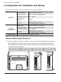
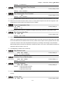
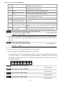
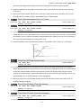
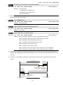
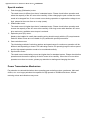
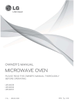
Minimum Mounting Clearances
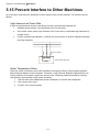
; The drive installation can be on a platform or on the wall. The left and middle figures show the
drive installation on a platform from the front and the side-view. The right figure shows wall
mounting. Both platform mounting and wall mounting are required to keep minimum mounting
clearances for good ventilation.
A
B
20mm
15mm
C
20mm
1-4
D
8mm
Chapter 1 Introduction |DD Series
CAUTION!
1.
2.
3.
4.
Mount the AC motor drive vertically on a flat vertical surface by using bolts or screws. Other
directions are not allowed.
The AC motor drive will generate heat during operation. Allow sufficient space around the unit
for heat dissipation. When the AC motor drive is installed in a confined space (e.g. cabinet),
the surrounding temperature must be with good ventilation. DO NOT install the AC motor drive
in a space with bad ventilation.
The heat sink temperature may rise to 90°C when running. The material on which the AC
motor drive is mounted must be noncombustible and be able to withstand this high
temperature.
When installing multiple AC motor drives in the same cabinet, they should be adjacent in a row
with enough space in-between. When installing one AC motor drive below another one, use a
metal separation barrier between the AC motor drives to prevent mutual heating.
NOTE
Prevent fiber particles, scraps of paper, saw dust, metal particles, etc. from adhering to the heatsink.
It is strongly recommend to mount the AC motor drive to inflammable materials such as metal for
fire prevention.
1-5
Chapter 1 Introduction |DD Series
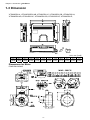
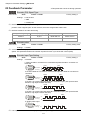
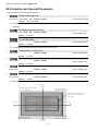
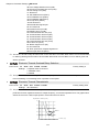
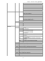
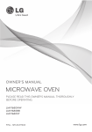
1-3 Dimension
VFD002DD21A; VFD002DDDD21AB; VFD002DD21C; VFD002DD21CB; VFD004DD21A;
VFD004DD21AB; VFD004DD21C; VFD004DD21CB; VFD002DD21E; VFD004DD21E;
Unit: mm [inch]
W
215.0
[8.46]
W1
204.0
[8.03]
W2
204.0
[8.03]
H
170.0
[6.69]
H1
138.5
[5.45]
H2
15.0
[0.59]
Dimensions for Motor
ECMD-B9120GMS
1-6
H3
15.1
[0.59]
H4
15.5
[0.61]
D
55.0
[2.17]
D1
8.5
[0.34]
Φ1
5.0
[0.20]
Φ2
7.0
[0.28]
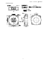
Chapter 1 Introduction |DD Series
ECMD-B9160GMS
1-7
Chapter 2 Wiring|DD Series
Chapter 2 Wiring
After removing the front cover, examine if the power and control terminals are clearly noted. Please
read following precautions before wiring.
; Make sure that power is only applied to the R/L1, S/L2, T/L3 terminals. Failure to comply may
result in damage to the equipments. The voltage and current should lie within the range as
indicated on the nameplate (Chapter 1-1).
; All the units must be grounded directly to a common ground terminal to prevent lightning strike or
electric shock.
; Please make sure to fasten the screw of the main circuit terminals to prevent sparks which is made
by the loose screws due to vibration
; It is crucial to turn off the AC motor drive power before any wiring installation is
made. A charge may still remain in the DC bus capacitors with hazardous voltages
DANGER
even if the power has been turned off therefore it is suggested for users to measure
the remaining voltage before wiring. For your personnel safety, please do not
perform any wiring before the voltage drops to a safe level < 25 Vdc. Wiring
installation with remaining voltage condition may cause sparks and short circuit.
; Only qualified personnel familiar with AC motor drives is allowed to perform
installation, wiring and commissioning. Make sure the power is turned off before
wiring to prevent electric shock.
; When wiring, please choose the wires with specification that complies with local
regulation for your personnel safety.
; Check following items after finishing the wiring:
1.
Are all connections correct?
2.
No loose wires?
3.
No short-circuits between terminals or to ground?
2-1
Chapter 2 WiringDD Series
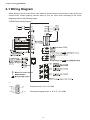
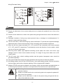
2-1 Wiring Diagram
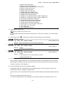
When wiring for an AC motor drive, user needs to connect wires to two sections, main circuit and
control circuit. Please properly connect wires to your AC motor drive according to the circuit
diagram provide in the following pages
VFD-DD Basic Wiring Diagram
G ND
A
ZZ
+12V
5 4 3 2 1
9 8 7 6
*1
B
Induction motor: A, B, +5V, GND
+5V
Permanent magnet motor: A, B, Z, Z-, +5V, GND
2-2
Chapter 2 Wiring|DD Series
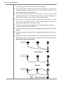
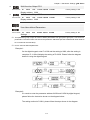
Wiring/Terminals Setting
Used with internal power (+24Vdc)
Used with external power
MI1
MI1
MI2
~
MI2
~
MI5
MI5
COM
+
+24V
COM
External +24V power
+24V
COM
CAUTION!
; The wiring of main circuit and control circuit should be separated to prevent erroneous actions.
; Please use shield wire for the control wiring and not to expose the peeled-off net in front of the
terminal.
; Please use the shield wire or tube for the power wiring and ground the two ends of the shield wire
or tube.
; Damaged insulation of wiring may cause personal injury or damage to circuits/equipment if it
comes in contact with high voltage.
; The AC motor drive, motor and wiring may cause interference. To prevent the equipment damage,
please take care of the erroneous actions of the surrounding sensors and the equipment.
; When the AC drive output terminals U/T1, V/T2, and W/T3 are connected to the motor terminals
U/T1, V/T2, and W/T3, respectively. To permanently reverse the direction of motor rotation, switch
over any of the two motor leads.
; With long motor cables, high capacitive switching current peaks can cause over-current, high
leakage current or lower current readout accuracy. For usage of long motor cables use an AC
output reactor.
; The AC motor drive, electric welding machine and the greater horsepower motor should be
grounded separately.
; Use ground leads that comply with local regulations and keep them as short as possible.
; No braking resistor is built in the VFD-DD series, it can install braking resistor for those occasions
that use higher load inertia or frequent start/stop. Refer to Appendix B for details.
; Multiple VFD-DD units can be installed in one location. All the units should be grounded directly to
a common ground terminal, as shown in the figure below. Ensure there are no ground loops.
; The wiring of main circuit and control circuit should be separated to prevent
erroneous actions.
; Please use shield wire for the control wiring and not to expose the peeled-off
net in front of the terminal.
; Please use the shield wire or tube for the power wiring and ground the two
ends of the shield wire or tube.
2-3
Chapter 2 Wiring|DD Series
; Damaged insulation of wiring may cause personal injury or damage to
circuits/equipment if it comes in contact with high voltage.
; The AC motor drive, motor and wiring may cause interference. To prevent the
equipment damage, please take care of the erroneous actions of the
surrounding sensors and the equipment.
; The AC drive output terminals U/T1, V/T2, and W/T3 should connect to the
motor terminals U/T1, V/T2, and W/T3 respectively. To reverse the direction of
motor rotation, please switch over any of the two motor leads.
; With long motor cables, high capacitive switching current peaks can cause
over-current, high leakage current or lower current readout accuracy. For
longer motor cables use an AC output reactor.
; The AC motor drive, electric welding machine and the greater horsepower
motor should be grounded separately.
; Use ground leads that comply with local regulations and keep them as short as
possible.
; Use ground leads that comply with local regulations and keep them as short as
possible.
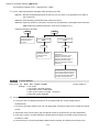
; Multiple AC drives can be installed in one location. All the units should be
grounded directly to a common ground terminal, as shown in the figure below.
Ensure there are no ground loops.
grouning
terminals
Excellent
grouning
terminals
Good
grouning
terminals
Not allowed
2-4
Chapter 2 Wiring|DD Series
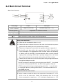
2-2 Main Circuit Terminal
Main Circuit Terminal
L1
L2
L1
L2
U/T1
V/T2
E
W/T3
Mo tor
IM/PM
E
Wire Gauge
14-12 AWG.
(2.075-3.332mm2)
Torque
Wire Type
5.2kgf-cm (4.5in-lbf)
Stranded copper only,75℃
Terminal Symbol
L1, L2
Explanation of Terminal Functions
AC line input terminals
U/T1, V/T2, W/T3 AC drive output terminals for connecting 3-phase induction motor
E
Earth connection, please comply with local regulations.
Mains power terminals:
; Power can be connected to either L1 or L2.
; Please make sure to fasten the screw of the main circuit terminals to prevent
sparks which is made by the loose screws due to vibration
; Please use voltage and current within the regulation shown in Appendix A.
; For the AC motor drive built-in with a general type of GFCI (Ground Fault
Circuit Interrupter), it is suggested to select a current sensor with sensitivity
of 200mA, and not less than 0.1-second detection time to avoid nuisance
tripping. When selecting a GFCI that is specially designed for an AC motor
drive, please select tje current sensor with sensitivity of 30mA or above.
; Please use the shield wire or tube for the power wiring and ground the two
ends of the shield wire or tube.
Do NOT run/stop AC motor drives by turning the power ON/OFF. You should
use control circuit terminal OD, CD or the OD on the keypad (or CD) and
STOP key to control running or stopping of the motor drive.
If you still need
to run/stop AC drives by turning power ON/OFF, it is recommended to do so
only ONCE per hour.
Output terminals for main circuit:
; When it needs to install the filter at the output side of terminals U/T1, V/T2,
W/T3 on the AC motor drive. Please use inductance filter. Do not use
phase-compensation capacitors or L-C (Inductance-Capacitance) or R-C
2-5
Chapter 2 Wiring|DD Series
(Resistance-Capacitance), unless approved by Delta.
; DO NOT connect phase-compensation capacitors or surge absorbers at the
output terminals of AC motor drives.
; Use a well-insulated motor, suitable for inverter operation.
2-6
Chapter 2 WiringDD Series
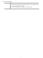
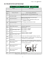
2-3 Control Circuit Terminal
DCM COM 24V OD
Terminal
Symbol
CD
MI5 MI4 MI3 MI2 MI1 MCM MO3 MO2 MO1
RC2 RA2 RB2 RC1 RA1 RB1
Torque
Wire Gauge
5 kgf-com (6.9 in-lbf)
18-12 AWG (0.8107-3.332mm2)
Terminal Function
Factory Setting (NPN Mode)
OD
Door Open to Stop
OD-DCM: ON: Open ; OFF: Decelerate to stop
CD
Door Close to Stop
CD-DCM: ON: Close; OFF: Decelerate to stop
MI1
Multi-function Input 1
MI2
Multi-function Input 2
MI3
Multi-function Input 3
Refer to Pr. 02-01~02-05 for programming of
Multi-function Inputs 1~5.
ON: the input voltage is 24Vdc(Max: 30Vdc), input
MI4
Multi-function Input 4
MI5
Multi-function Input 5
COM
impedance is 3.75kΩ
OFF: leakage current tolerance is 10μA.
Digital control signal common
Common for digital inputs
+E24V
Digital Signal Common
+24V 80mA
DCM
Digital Signal Common
Common for digital inputs
RA1
Multi-function Relay1 output
(N.O.) a
Resistive Load:
Multi-function Relay1 output
(N.C.) b
Multi-function Relay1
common
Multi-function Relay2 output
(N.O.) a
Multi-function Relay2
common
Multi-function Output 1
(Photocoupler)
5A(N.O.)/3A(N.C.) 24VDC
RB1
RC1
RA2
RB2
RC2
5A(N.O.)/3A(N.C.) 240VAC
Inductive Load:
1.5A(N.O.)/0.5A(N.C.) 240VAC
1.5A(N.O.)/0.5A(N.C.) 24VDC
To output any monitoring signal including in operation ,
frequency attained, overload indicator…etc, please refer
to Pr.02-08~02-12 for MO selection.
To output any monitoring signal including in operation ,
MO1
Multi-function Output 1
(Photocoupler)
frequency attained, overload indicator…etc, please refer
to Pr.03-01for MO selection.
Max: 48Vdc
50mA
MO1~MO2-DCM
MO2
MO3
Multi-function Output 2
(Photocoupler)
MO1~MO2
Multi-function Output 3
(Photocoupler)
MCM
Internal Circuit
MCM
Multi-function output common
Max 48Vdc 50mA
* Analog control signal wiring size: 18 AWG (0.75 mm2) with shielded wire.
2-7
Chapter 2 Wiring|DD Series
Digital Inputs (CD, OD, MI1~MI5, COM)
; When using contacts or switches to control the digital inputs, please use high quality
components to avoid contact bounce.
Digital Outputs (MO1, MO2, MO3, MCM)
; Make sure to connect the digital outputs to the right polarity, see wiring diagrams.
; When connecting a relay to the digital outputs, connect a surge absorber or fly-back diode
across the coil and check the polarity.
2-8
Chapter 3 Keypad and Startup |DD Series
Chapter 3 Keypad and Start-up
3-1 Operation Method
3-2 Keypad Descriptions
; Make sure that the wiring is correct. In particular, check that the output terminals
U/T1, V/T2, W/T3 are NOT connected to power and that the drive is well grounded.
; Verify that no other equipment is connected to the AC motor
; Do NOT operate the AC motor drive with humid hands.
; Verify that there are no short-circuits between terminals and from terminals to
ground or mains power.
; Check if all connections are proper, there should be no loose terminals, connectors
or screws.
; Make sure that the front cover is well installed before applying power.
; When AC motor drive and motor are not function properly, stops operation
immediately and follow malfunction diagnosis to verify the reason of fault. Do not
touch U/T1, V/T2, W/T3 before the main power L1, L2 are turned off or electric
shock may occur.
3-1
Chapter 3 Keypad and Startup |DD Series
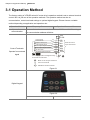
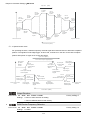
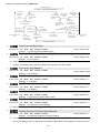
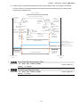
3-1 Operation Method
The factory setting of VFD-DD series AC motor drive’s operation method is set to external terminal
control. But it is just one of the operation methods. The operation method can be via
communication, control terminals settings or optional digital keypad. Please choose a suitable
method depending on application and operation rule.
Operation Method
Operate from
communication
Control TerminalsOperate from external
signal
Frequency Source
Operation Command Source
Please refer to the communication address 2000H and 2119H settings in
the communication address definition.
Doo r Op en
Doo r Clo se
Op en L imi t In pu t
Clo se Li mit Inp ut
Doo r Op en S pe ed S witch
Doo r Op en S pe ed S witch
No Fun ction
Dig ital Si gna l Common
24V
COM
OD
CD
MI1
MI2
Mul ti-Fu nctio n
Inp ut Ter mi na ls
MI3
MI4
MI5
DCM
NOTE
Do n ot ap ply ma ins vol tag e di re ctl y
to th e ab ove te rmin al s
E
Main circui t Ou tput Te rmin al
Co ntrol Te rmin al
Shie lde d Le ads & Ca bl es
Figure 3-1
Digital Keypad
Figure 3-2
UP/DOWN key
3-2
RUN, STOP/RESET key
Chapter 3 Keypad and Startup |DD Series
3-2 Keypad Descriptions
Descriptions of Digital Keypad Outlook
Door Close
Door Close Complete
Fault Indicate
Door Open
Door Open Complete
LED Disp lay
Di spla ys output frequency, cu rren t,
al l para me ter sett ing s an d fau lt co nten t
UP/DOWN Key
Select and change parameters
Ent er Ke y
Pro gram/Fu nctio n
To read o r mod ify d ri ve's para meters
Displ ay AC d ri ve 's status an d se tting
LED Indi cates
STOP/RESET Key
To stop s and resets th e pa ra me ter
a fter fa ul t o ccurs
Power Indi cates
Close Door/Open Do or Key
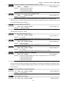
Descriptions of Display Items
Display Message
Descriptions
Displays the AC drive Master Frequency.
Displays the actual output frequency present at the motor.
User defined unit (where U = F x Pr.0-04)
Displays the output current present at terminals U/T1, V/T2, and W/T3.
Display counting value
Display the selected parameter
Displays the actual stored value of the selected parameter.
External Fault.
Display “End” for approximately 1 second if input has been accepted and
saved automatically.
Display “Err”, if the input is invalid.
How to Operate the Digital Keypad
STA RT
Selection Mode
GO START
To set parameters
Paramete r settin g co mple te.
MODE
MODE
ENTER
Paramete r settin g erro r .
NOTE: In the p aramete r settin g mo de , u se r can retu rn to MODE se le cti on by pressing
3-3
MODE
.
Chapter 4 Parameter Settings|DD Series
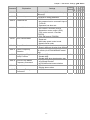
Chapter 4 Parameter Settings
4-1 Summary of Parameter Settings
4-2 Summary of Detailed Parameter Settings
The VFD-DD parameters are divided into 12 groups by property for easy setting. Most of the parameter
settings can be done before start-up and readjustment of the parameter will not be needed.
Group 00: System Parameters
Group 01: Motor Parameters
Group 02: Input/Output Parameters
Group 03: Feedback Parameters
Group 04: Door Open Parameters
Group 05: Door Close Parameters
Group 06: Protection and Special Parameters
Group 07: Control Parameters
Group 08: Multi-step Speed Parameters
Group 09: Communication Parameters
Group 10:User-defined Parameters
Group 11: View User-defined Parameters
4-1
Chapter 4 Parameter Settings|DD Series
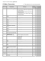
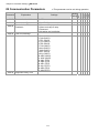
4-1 Summary of Parameter Settings
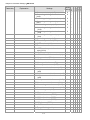
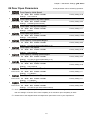
00 System Parameters
Explanation
Settings
Factory
Setting
VF
VFP
SVC
FOC
FOC
Parameter
: This parameter can be set during operation.
Read ○ ○ ○ ○
Identity Code of AC motor 0: 200w
2: 400w
only
drive
Read ○ ○ ○ ○
00.01 Rated Current Display of 0: 1.50A
2:
2.50A
only
AC motor drive
0: No function
0
○ ○ ○ ○
00.02 Parameter Reset
1: Parameters locked
8: Keypad locked
10: All parameters are reset to factory
setting (33.3Hz, 230V)
0:
Display
the frequency command value
0
○ ○ ○ ○
00.03 Start-up Display Selection
(F)
1: Display the actual output frequency
(H)
2: Display the content of user-defined
unit (U)
3: Display the output current (A)
2
○ ○ ○ ○
00.04 Content of Multi Function 0: Display output current (A )
1: Display actual frequency (Hz)
Display
2: Display DC-BUS voltage ( U)
3: Display output voltage( E )
4: Display power factor angle (n.)
5: Display output power (kW)
6: Display motor angle speed (HU)
7: Display the drive’s estimated output
torque (kg-m)
8: Display PG pulse input position
9: Display the electrical angle
10: Display IGBT temperature(oC)
11: Display digital input ON/OFF status
12: Display digital output ON/OFF status
13: Display current multi-step speed
14: Display the corresponding CPU pin
status of digital input
15: Display the corresponding CPU pin
status of digital input 16:Actual
output voltage when malfunction
17: Actual DC-BUS voltage when
malfunction
18: Actual output frequency when
malfunction
19: Actual output current when
malfunction
20: Actual frequency command when
malfunction
21: Door width in % or step speed
22: Door width(pulse)
23: Over modulation indication
00.00
4-2
○
○
○
○
○
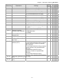
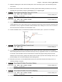
Parameter
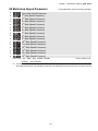
00.05
Explanation
Software version
00.06 Password Input
00.07 Password Set
00.08
Control Method
00.09
Door Control Mode
00.10
Output Direction
00.11 Carrier Frequency
Selection
00.12 Auto Voltage Regulation
(AVR) Function
00.13 Source of the Master
Frequency Command
00.14
Demo Mode
00.15 Frequency Testing
Command
Settings
Factory
Setting
Read only(Different versions will display #.##
differently)
0~9999
0
0~2:times of wrong password
0~9999
0
0: No password set or successful input in
Pr.00-06
1: Password has been set
0: V/f control
0
1: V/f Control + Encoder (VFPG)
2: Sensorless vector control (SVC)
3: FOC vector control + Encoder
(FOCPG)
8: FOC PM control (FOCPM)
0: Distance control mode
3
1: Reserved
2: Multi-step speed control mode
3: Speed control mode
0: Runs in same direction as setting
0
1: Runs in different direction than setting
02~15 kHz
10
02~10kHz (for VFDXXXDDXXE model
only)
0: Enable AVR
0
1: Disable AVR
2: Disable AVR when deceleration stop
0: by digital keypad input
1
1: by external terminal
2: by RS-485 serial communication
0: Disable
0
1: Display demo action
0~120.00 Hz
0
4-3
VF
VFP
SVC
FOC
FOC
Chapter 4 Parameter Settings|DD Series
○ ○ ○ ○ ○
○ ○ ○ ○ ○
○ ○ ○ ○ ○
○ ○ ○ ○ ○
○ ○ ○ ○ ○
○ ○ ○ ○ ○
○ ○ ○ ○ ○
○ ○ ○ ○ ○
○ ○ ○ ○ ○
○ ○ ○ ○ ○
○ ○ ○ ○ ○
Chapter 4 Parameter Settings|DD Series
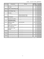
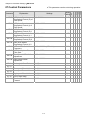
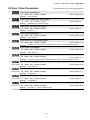
01 Motor Parameters
01.00
01.01
01.02
01.03
01.04
01.05
01.06
01.07
01.08
01.09
01.10
01.11
01.12
01.13
01.14
01.15
Explanation
Settings
Factory
Setting
VF
VFP
SVC
FOC
FOC
Parameter
: This parameter can be set during operation.
0: No function
0
1: Auto-tuning for PM motor parameters
(brake locked)
2: Auto-tuning for PG offset angle without
load (Pr.01.09)
3: Auto-tuning for PG offset angle with
load (Pr.01.09)
(20~120%)*00.01
Amps
1.00
Full-load Current of motor
(PM)
0.06
Rated power of Motor (PM) 0.00~655.35kW
○
Motor Auto Tuning (PM)
Rated speed of Motor (rpm) 0~65535
(PM)
2~96
Number of Motor Poles
(PM)
0.0~655.35Ω
Rs of Motor parameter
(PM)
0.0~6553.5mH
Ld of Motor Parameter
(PM)
0.0~6553.5mH
Lq of Motor Parameter
(PM)
Back Electromotive Force 0.0~6553.5Vrms
(PM)
Angle between Magnetic 0.0~360.0°
Pole and PG Origin (PM)
0:No function
Magnetic Pole
1:Reset magnetic pole position
Re-orientation (PM)
0: No function
1: Rolling test
2: Static test
3: Reserved
Full-load Current of Motor (20~120%)*00.01 Amps
(IM)
Rated power of Motor (IM) 0.00~655.35kW
Motor Auto Tuning (IM)
Rated speed of Motor (rpm) 0~65535
(IM)
Number of Motor Poles (IM) 2~48
○
○
250
○
16
○
13.900
○
169.4
○
169.4
○
0.0
○
360.0
○
0
○
0
○ ○
1.00
○ ○ ○ ○
0.06
○ ○
250
○ ○ ○
16
○ ○ ○ ○
01.16
No-load Current of Motor
(IM)
00~ Pr.01.12 factory setting
#.##
○ ○ ○
01.17
Rs of Motor (IM)
0.000~65.535Ω
0.000
○ ○
01.18
Rr of Motor (IM)
0.000~65.535Ω
0.000
○ ○
01.19
Lm of Motor (IM)
0.0~6553.5mH
0.0
○ ○
01.20
Lx of Motor (IM)
0.0~6553.5mH
0.0
○ ○
01.21 Torque Compensation Time 0.001~10.000sec
Constant
4-4
0.020
○
Parameter
Explanation
01.22 Slip Compensation Time
Constant
Settings
0.001~10.000sec
01.23 Torque Compensation Gain 00~10
0.00~10.00
01.24 Slip Compensation Gain
01.25 Slip Deviation Level
00~1000% (0:Disable)
01.26 Detection Time of Slip
Deviation
0.0~10.0sec
01.27 Over Slip Treatment
0: Warn and keep operation
1: Warn and ramp to stop
2: Warn and coast to stop
00~10000 (0:Disable)
01.28 Hunting Gain
Factory
Setting
VF
VFP
SVC
FOC
FOC
Chapter 4 Parameter Settings|DD Series
0.100
○
0
○ ○
0.00 ○ ○ ○
0
○ ○ ○
1.0
○ ○ ○
0
○ ○ ○
2000
○ ○ ○
01.29
Accumulative Motor
Operation Time (Min.)
0~1439
0
○ ○ ○ ○
01.30
Accumulative Motor
Operation Time (day)
0~65535
0
○ ○ ○ ○
01.31
Maximum Output
Frequency
10.00~120.00Hz
50
○ ○ ○ ○ ○
01.32
Output Frequency 1
(Base frequency /Motor
rated frequency)
0.00~120.00Hz
50
○ ○ ○ ○ ○
01.33
Output Voltage 1(Base
voltage/Motor rated
voltage)
0.0V~240.0V
220.0 ○ ○ ○ ○ ○
01.34
Output Frequency 2
0.00~120.00Hz
0.50
○ ○
0.0V~240.0V
5.0
○ ○
0.00~120.00Hz
0.50
○ ○
0.0V~240.0V
5.0
○ ○
0.00~120.00Hz
0.00
○ ○ ○ ○
0.0V~240.0V
0.0
○ ○
01.35 Output Voltage 2
01.36
Output Frequency 3
01.37 Output Voltage 3
01.38
Output Frequency 4
01.39 Output Voltage 4
4-5
Chapter 4 Parameter Settings|DD Series
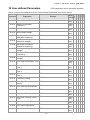
02 Input/Output Parameters
Explanation
Settings
Factory
Setting
VF
VFP
SVC
FOC
FOC
Parameter
: This parameter can be set during operation.
0
○ ○ ○ ○ ○
02.01
0: 2-wire mode 1 (when power is on,
operation begins)
1: 2-wire mode 1 (when power is on, no
operation)
2: 2-wire mode 2 (when power is on,
operation begins)
3: 2-wire mode 2 (when power is on, no
operation)
Multi-Function Input 1 (MI1) 0: No function
14
○ ○ ○ ○ ○
02.02
Multi-Function Input 2 (MI2) 1: Multi-step speed command 1
15
○ ○ ○ ○ ○
02.03
Multi-Function Input 3 (MI3) 2: Multi-step speed command 2
16
○ ○ ○ ○ ○
02.04
Multi-Function Input 4 (MI4) 3: Multi-step speed command 3
17
○ ○ ○ ○ ○
02.05
Multi-Function Input 5 (MI5) 4: Multi-step speed command 4
0
○ ○ ○ ○ ○
02.00
2-wire/3-wire Operation
Control
02.06 Digital Terminal Input
Debouncing Time
5: Fault reset
6: Low speed operation
○ ○ ○ ○ ○
7: OD/CD command for low speed
operation
8: 1st, 2nd acceleration/deceleration time
selection
9: Force stop (NO) input
○ ○ ○ ○ ○
10: Demo mode
○ ○ ○ ○ ○
11: Emergency stop (NO) input
○ ○ ○ ○ ○
12: Source of operation command
(Keypad/External terminals)
13: Parameter lock enable (NC)
○ ○ ○ ○ ○
14: Door open complete signal
○ ○ ○ ○ ○
15: Door close complete signal
○ ○ ○ ○ ○
16: Door open speed switch signal
○ ○ ○ ○ ○
17: Door close speed switch signal
○ ○ ○ ○ ○
18: Open allowance signal
○ ○ ○ ○ ○
19: Screen signal input
○ ○ ○ ○ ○
20: Door curve signal input for 2nd set
door open/close
21: Reset signal input
○ ○ ○ ○ ○
22: Input system security circuit
confirmation signal (DCC)
23: Input enforced door closing signal
(NUD)
0.001~30.000sec
○ ○ ○ ○ ○
○ ○ ○ ○ ○
○ ○ ○ ○ ○
○ ○ ○ ○ ○
○ ○ ○ ○ ○
○ ○ ○ ○ ○
○ ○ ○ ○ ○
0.005 ○ ○ ○ ○ ○
02.07 Digital Input Operation
Direction
0~65535
60
○ ○ ○ ○ ○
02.08 Multi-function Output
(Relay1)
0: No function
16
○ ○ ○ ○ ○
4-6
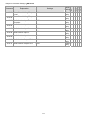
Parameter
Explanation
Settings
Factory
Setting
VF
VFP
SVC
FOC
FOC
Chapter 4 Parameter Settings|DD Series
02.09 Multi-function Output
(Relay2)
1: AC drive in operation
17
○ ○ ○ ○ ○
02.10 Multi-function Output
(MO1)
2: Zero speed frequency signal
(including STOP)
0
○ ○ ○ ○ ○
02.11 Multi-function Output
(MO2)
3: AC drive ready
0
○ ○ ○ ○ ○
0
○ ○ ○ ○ ○
02.12 Multi-function Output
(MO3) (Communication)
4: Low voltage warning(Lv)
5: Fault indication
○ ○ ○ ○ ○
6: Overhead warning (Pr.06.09)
○ ○ ○ ○ ○
7: Detection of braking resistor action
level
8: Warning indication
○ ○ ○ ○ ○
9: Over voltage warning
○ ○ ○ ○ ○
10: OD command
○ ○ ○ ○ ○
11: CD command
○ ○ ○ ○ ○
12: Demo Indication
○ ○ ○ ○ ○
13: Demo complete
○ ○ ○ ○ ○
14: Emergency stop indication
○ ○ ○ ○ ○
15: Force stop indication
○ ○ ○ ○ ○
16: Door close complete (limit) signal
output
17: Door open complete (limit) signal
output
18: Door close error
19: Position Complete Signal
○ ○ ○ ○ ○
20: Position Detection 1(for door close
only)
21: Position Detection 2(for door close
only)
22: Position Detection 3(for door close
only))
23: Position Detection 1(for door open
only)
24: Position Detection 2(for door open
only)
25: Position Detection 3(for door open
only)
26: PG feedback error
27: output signal when unable to open
the door
28: over torque (OT1)
0~65535
○ ○ ○ ○ ○
○ ○ ○ ○ ○
○ ○ ○ ○ ○
○ ○ ○ ○ ○
○ ○ ○ ○ ○
○ ○ ○ ○ ○
○ ○ ○ ○ ○
○ ○ ○ ○ ○
○ ○ ○ ○ ○
○ ○ ○ ○ ○
○ ○ ○ ○ ○
○ ○ ○ ○ ○
0
○ ○ ○ ○ ○
○ ○ ○ ○ ○
02.14 Position Detection Signal 1 0.0~100.0%
02.15 Position Detection Signal 2 0.0~100.0%
25.0
○ ○ ○ ○ ○
12.5
○ ○ ○ ○ ○
02.16 Position Detection Signal 3 0.0~100.0%
7.5
○ ○ ○ ○ ○
02.13 Multi-function Output
Direction
4-7
Chapter 4 Parameter Settings|DD Series
4-8
Chapter 4 Parameter Settings|DD Series
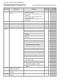
03 Feedback Parameters
This parameter can be set during
Parameter
Explanation
Settings
Factory
Setting
7
Encoder (PG) Signal Type 0: No function
1: ABZ
7: PWM pulse
1~25000
256
03.01 Encoder pulse
1
03.02 Encoder Input Type Setting 0: Disable
1: Phase A leads in a forward run
command and phase B leads in a
reverse run command
2: Phase B leads in a forward run
command and phase A leads in a
reverse run command
3: Phase A is a pulse input and phase B
is a direction input. (low input=reverse
direction, high input=forward direction)
4: Phase A is a pulse input and phase B
is a direction input. (low input=forward
direction, high input=reverse direction)
5: Single-phase input
2
03.03 Encoder Feedback Fault 0: Warn and keep operation
1:
Warn
and
ramp
to
stop
Treatment (PGF1, PGF2)
2: Warn and stop operation
1.0
03.04 Detection Time for Encoder 0.0~10.0sec
Feedback Fault
115
03.05 Encoder Stall Level (PGF3) 0~120% (0:Disable)
0.1
0.0~2.0sec
03-06 Encoder Stall Detection
Time
0~50% (0:Disable)
50
03.07 Encoder Slip Range
(PGF4)
0.5
0.0~10.0sec
03.08 Encoder Slip Detection
Time
2
03.09 Encoder Stall and Slip Error 0: Warn and keep operation
1:
Warn
and
ramp
to
stop
Treatment
2: Warn and coast to stop
0.10~120.00Hz
5.0
03.10 Door Width Auto-tuning
Frequency
0: Disable
0
03.11 Door Width Auto-tuning
1: Enable
1~9999
8800
Door
Width
Pulse
(Unit:1)
03.12
0~9999 (Unit:10000)
0
03.13 Door Width Pulse
(Unit:10000)
03.00
4-9
VF
VFP
SVC
FOC
FOC
operation.
○
○ ○
○
○ ○
○
○ ○
○
○ ○
○
○ ○
○ ○ ○ ○
○ ○ ○ ○
○ ○ ○ ○
○ ○ ○ ○
○ ○ ○
○ ○ ○ ○ ○
○ ○ ○ ○ ○
○ ○ ○ ○ ○
○ ○ ○ ○ ○
Chapter 4 Parameter Settings|DD Series
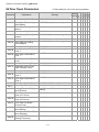
04 Door Open Parameters
Explanation
Settings
04.00 Door Open by Initial Speed 0.00~120.0Hz
0~65535 (Unit: pulses number)
04.01 Door Open Distance by
Initial Speed
0~20.0s
04.02 Door Open Time by Initial
Speed
0.00~120.0Hz
04.03 Door Open High Speed 1
Factory
Setting
VF
VFP
SVC
FOC
FOC
Parameter
This parameter can be set during operation.
2.00
○ ○ ○ ○ ○
300
○ ○ ○ ○ ○
1.0
○ ○ ○ ○ ○
15.00 ○ ○ ○ ○ ○
04.04 Door Open by Final Speed
Begins
0.0~100.0% (Door width setting in %)
90.0
○ ○ ○ ○ ○
04.05 Door Open Final Speed
0.00~120.0Hz
5.00
○ ○ ○ ○ ○
04.06 Door Open by Holding
Speed Begins
0.0~100.0% (Door width setting in %)
95.0
○ ○ ○ ○ ○
04.07 Door Open Holding Speed
0.00~120.0Hz
2.00
○ ○ ○ ○ ○
04.08 Door Open Acceleration
Time 1
0.1~3600sec
1.0
○ ○ ○ ○ ○
04.09 Door Open Deceleration
Time 1
0.1~3600sec
1.0
○ ○ ○ ○ ○
04.10 Door Open Holding Torque
Level
0.0~150.0% (AC drive’s rated current)
50.0
○ ○ ○ ○ ○
04.11 Door Open Holding Torque
0.0~100.0% (AC drive’s rated current)
30.0
○ ○ ○ ○ ○
04.12 Response Time of Door
Open Holding Torque
0.01~10.00sec
0.20
○ ○ ○ ○ ○
04.13 Door Open High Speed 2
0.00~400.0Hz
30.00 ○ ○ ○ ○ ○
04.14 Door Open Acceleration
Time 2
0.1~3600sec
1.0
○ ○ ○ ○ ○
04.15 Door Open Deceleration
Time 2
0.1~3600sec
1.0
○ ○ ○ ○ ○
04.16 Door Open Holding Torque 2 0.0~150.0% (AC drive’s rated current)
04.17 Door Open Time-out Setting 0.0~180.0sec (0.0 sec: Disable)
0.0
○ ○ ○ ○ ○
0.0
○ ○ ○ ○ ○
04.18 Holding Time for OD (Open 0.0~999.9sec (999.9 sec for always
holding)
Door)Terminal
0.0~10.0sec
04.19 Door Open Acceleration
Time of S1 Curve
0.0~10.0sec
04.20 Door Open Acceleration
Time of S2 Curve
00~100%
04.21 Door Open DC Brake
Current Level
04.22 Door Open DC Brake Time 0.0~60.0sec
when Startup
04.23 Door Open DC Brake Time 0.0~60.0sec
when Stopping
0.00~120.00Hz
04.24 Door Open DC Brake
Starting Frequency
0.0
○ ○ ○ ○ ○
0.0
○ ○ ○ ○ ○
0.0
○ ○ ○ ○ ○
4-10
0
○ ○ ○
0.0
○ ○ ○ ○ ○
0.0
○ ○ ○ ○ ○
0.00
○ ○ ○ ○
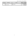
Parameter
04.25
Explanation
Current Level when unable
to open the door
Settings
0.0~150.0% (rated motor current)
0.0:No function
4-11
Factory
Setting
VF
VFP
SVC
FOC
FOC
Chapter 4 Parameter Settings|DD Series
0
○ ○ ○ ○ ○
Chapter 4 Parameter Settings|DD Series
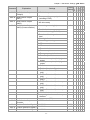
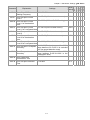
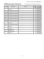
05 Door Close Parameters
Explanation
Settings
05.00 Door Close Initial Speed
0.00~120.0Hz
05.01 Door Close Distance by
Initial Speed
0~65535 (Unit: pulses number)
05.02 Door Close Time by Initial 0~20.0s
Speed
05.03 Door Close High Speed 1 0.00~120.0Hz
Factory
Setting
VF
VFP
SVC
FOC
FOC
Parameter
This parameter can be set during operation.
2.00
○ ○ ○ ○ ○
0
○ ○ ○ ○ ○
0
○ ○ ○ ○ ○
15.00 ○ ○ ○ ○ ○
05.04 Door Close by Final Speed 0.0~100.0% (Door width setting in %)
Begins
0.00~120.0Hz
05.05 Door Close Final Speed
10.0
○ ○ ○ ○ ○
5.00
○ ○ ○ ○ ○
0.0~100.0% (Door width setting in %)
5.0
○ ○ ○ ○ ○
2.00
○ ○ ○ ○ ○
1.0
○ ○ ○ ○ ○
1.0
○ ○ ○ ○ ○
50.0
○ ○ ○ ○ ○
20.0
○ ○ ○ ○ ○
○ ○ ○ ○ ○
05.06 Door Close by Holding
Speed Begins
05.07 Door Close Holding Speed 0.00~120.0Hz
0.1~3600sec
05.08 Door Close Acceleration
Time 1
05.09 Door Close Deceleration 0.1~3600sec
Time 1
05.10 Door Close Holding Torque 0.0~150.0% (Drive’s rated current)
Level 1
0.0~100.0% (Drive’s rated current)
05.11 Door Close Holding
Torque 1
05.12 Response Time of Door
Close Holding Torque
0.01~10.00sec
0.20
05.13 Door Close High Speed 2
0.00~120.0Hz
30.00 ○ ○ ○
05.14 Door Close Acceleration
Time 2
0.1~3600sec
1.0
○ ○ ○ ○ ○
05.15 Door Close Deceleration
Time 2
0.1~3600sec
1.0
○ ○ ○ ○ ○
05.16 Door Close Holding
Torque Level 2
0.0~150.0% (Ac drive’s rated current)
0.0
○ ○ ○ ○ ○
05.17 Door Close Time-out
Setting
0.0~180.0sec (0.0sec:Disable)
0.0
○ ○ ○ ○ ○
0.0
○ ○ ○ ○ ○
0.0
○ ○ ○ ○ ○
0.0
○ ○ ○ ○ ○
05.18 Holding Time for CD (Close 0.0~999.9sec (999.9sec is always
holding)
Door)Terminal
0.0~10.0sec
05.19 Door Close Acceleration
Time of S1 Curve
0.0~10.0sec
05.20 Door Close Acceleration
Time of S2 Curve
0~100%
05.21 Door Close DC Brake
Current Level
05.22 Door Close DC Brake Time 0.0~60.0sec
when Startup
05.23 Door Close DC Brake Time 0.0~60.0sec
when Stopping
4-12
0
○ ○ ○
0.0
○ ○ ○ ○ ○
0.0
○ ○ ○ ○ ○
Parameter
Explanation
05.24 Door Close DC Brake
Starting Frequency
05.25
Door Re-open Current
Level 1
05.26 Door Re-open Current
Level 1 for Acceleration
Area
Settings
Factory
Setting
VF
VFP
SVC
FOC
FOC
Chapter 4 Parameter Settings|DD Series
0.00~120.00Hz
0.00 ○ ○ ○ ○
0.0~150.0% (AC drive’s rated current)
100.0 ○ ○ ○ ○ ○
100~200% (100% is Pr.05.25 setting)
0.0~150.0%(Drive’s rated current)
05.27 Door Re-open Current
Level 1 for Low Speed Area
0.0~150.0%(Drive’s rated current)
05.28 Door Re-open Current
Level 2
0.0~150.0% (Drive’s rated current)
05.29 Door Re-open Current
Level 2 for Acceleration
Area
100~200%(100% is Pr.05.29 setting)
05.30 Door Re-open Current
Level 2 for Low Speed Area
door
width=100%;
05.31 Door Re-open Low Speed 1.0~99.0%(Total
range between 0%~Pr.05.31 is excluded
Boundary
from low speed detection area)
05.32 Door Re-open Acceleration 8.0~97.0%(Total door width =100%;
range between Pr.05.32~100% is the
Boundary
acceleration area)
0.1~3600sec
05.33 Door Close Error
Deceleration Time
0~10.0sec
05.34 Door Re-open Detection
Time
4-13
150
○ ○ ○ ○ ○
100.0 ○ ○ ○ ○ ○
100.0 ○ ○ ○ ○ ○
150
○ ○ ○ ○ ○
100.0 ○ ○ ○ ○ ○
2.0
○ ○ ○ ○ ○
70.0 ○ ○ ○ ○ ○
0.4
○ ○ ○ ○ ○
0.2
○ ○ ○ ○ ○
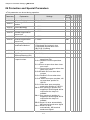
Chapter 4 Parameter Settings|DD Series
06 Protection and Special Parameters
Parameter
Explanation
Settings
Factory
Setting
VF
VFP
SVC
FOC
FOC
This parameter can be set during operation.
06.00 Software Braking Level
350.0~450.0Vdc
06.01 ED Setting of Brake
Resistor
0~100%
50
○ ○ ○ ○ ○
06.02 Current Boundary
0~250%
200
○ ○
06.03 Forward Motor Torque Limit 0~250%
0~250%
06.04 Forward Regenerative
Torque Limit
06.05 Reverse Motor Torque Limit 0~250%
200
○ ○
200
○ ○
200
○ ○
06.06 Reverse Regenerative
Torque Limit
0~250%
200
○ ○
06.07 Emergency/Force Stop
Deceleration Method
0:Coast to stop
1: Decelerate by 1st decel. time
2: Decelerate by 2nd decel. time
3:By Pr.05.33 setting
160.0~270.0Vdc
180.0 ○ ○ ○ ○ ○
0.0~110.0℃
85.0 ○ ○ ○ ○ ○
06.08 Low Voltage Level
06.09 High Temperature
Overheat Warning (OH)
06.10
Action after door
re-open/re-close
Bit 0=0:Not detecting incorrect
open/close limit
Bit 0=1:Detects incorrect open/close
limit
Bit 1=0:Door re-open when door close
error occur
Bit 1=1:Door will not re-open when door
close error occur
Bit 2=0:Enable S-Curve when door
re-open
Bit 2=1:Disable S-Curve when door
re-open
Bit 3=0: When door open complete, will
not reset door position to
100.0%.
Bit 3=1:When door open complete,
resets door position to 100.0%
Bit4=0 Door opening in position not
supported, limited signal will be
output after the torque is
enabled.
Bit4=1 Door opening in position is
supported, limited signal will be
output after the torque is
enabled.
Bit5=0 Reset LVn error automatically,
MO terminal sends error signal
Bit5=1 Reset LVn error
automatically, MO terminal
sends error signal
4-14
380.0 ○ ○ ○ ○ ○
3
2
○ ○ ○ ○ ○
○ ○ ○ ○ ○
Parameter
Explanation
06.11 Position Control Mode
06.12 Stall Current Level of
Position Mode
Settings
Factory
Setting
VF
VFP
SVC
FOC
FOC
Chapter 4 Parameter Settings|DD Series
Bit6=0 OD and CD signal are input at the
same time, but without reaction.
Bit6=1 OD and CD signal are input at the
same time and with door
opening
Bit7=0 When the running signal come
from an external terminal.
Pressing OD and CD buttons to
return to running status is not
supported when the drive is
stopped.
Bit7=1 When the running signal come
from an external terminal.
Pressing OD and CD buttons to
return to running status is
supported when the drive is
stopped.
0: No limit signal, detect by PG number
0
○ ○ ○ ○ ○
and current level.
1: Door open limit signal only, door close
by PG number or current level
detection.
2: Door close limit signal only,door open
by PG number or current level
detection.
3: Door open and close limit signal
4: Detect by PG number and also accept
external door open/close limit signal
5: No limit signal, detect by PG number
and current level. (For Pr.00-09=3
speed control mode)
0.0~200.0% (Drive’s rated current)
30.0 ○ ○ ○ ○ ○
06.13 Door Open/Close Holding 0.0~99.99sec
Time Before Next Demo
06.14 Times of Door Open/Close 0~9999
in Demo Mode (L)
06.15 Times of Door Open/Close 0~9999
in Demo Mode (H)
0: Disable
06.16 Clear Demo Mode Door
1: Clear (Pr.06.14 and Pr.06.15)
Open/Close Record
2.0
○ ○ ○ ○ ○
0
○ ○ ○ ○ ○
0
○ ○ ○ ○ ○
0
○ ○ ○ ○ ○
06.17
Present Fault Record
0: No fault
0
○ ○ ○ ○ ○
06.18
2nd Most Recent Fault
Record
1: Over-current during acceleration
(ocA)
0
○ ○ ○ ○ ○
06.19
3rd Most Recent Fault
Record
2: Over-current during deceleration
(ocd)
0
○ ○ ○ ○ ○
06.20
4th Most Recent Fault
Record
3: Over-current during steady speed
(ocn)
0
○ ○ ○ ○ ○
06.21
5th Most Recent Fault
Record
4: Reserved
0
○ ○ ○ ○ ○
06.22
6th Sixth Most Recent Fault 5: Reserved
Record
0
○ ○ ○ ○ ○
4-15
Parameter
Factory
Setting
VF
VFP
SVC
FOC
FOC
Chapter 4 Parameter Settings|DD Series
6: Over-current at stop (ocS)
0
○ ○ ○ ○ ○
7: Over voltage during acceleration
(ovA)
8 Over voltage during deceleration (ovd)
0
○ ○ ○ ○ ○
0
○ ○ ○ ○ ○
0
○ ○ ○ ○ ○
0
○ ○ ○ ○ ○
11: Low voltage during acceleration
(LvA)
12: Low voltage during deceleration
(Lvd)
13: Low voltage during steady speed
(Lvn)
14:Low voltage at stop (LvS)
0
○ ○ ○ ○ ○
0
○ ○ ○ ○ ○
0
○ ○ ○ ○ ○
0
○ ○ ○ ○ ○
15:Phase loss protection (PHL)
0
○ ○ ○ ○ ○
16:IGBT overheat (oH1)
0
○ ○ ○ ○ ○
17:Reserved
0
○ ○ ○ ○ ○
18: IGBT overheat protection circuit
error (tH1o)
19~20: Reserved
0
○ ○ ○ ○ ○
0
○ ○ ○ ○ ○
21: 150% 1Min, AC drive overload (oL)
0
○ ○ ○ ○ ○
22: Motor overload (EoL1 )
0
○ ○ ○ ○ ○
23~29: Reserved
0
○ ○ ○ ○ ○
30: Memory write-in error (cF1)
0
○ ○ ○ ○ ○
31: Memory read-out error (cF2)
0
○ ○ ○ ○ ○
32: Isum current detection error (cd0)
0
○ ○ ○ ○ ○
33: U-phase current detection error
(cd1)
34: V-phase current detection error (cd2)
0
○ ○ ○ ○ ○
0
○ ○ ○ ○ ○
35: W-phase current detection error
(cd3)
36: Clamp current detection error (Hd0)
0
○ ○ ○ ○ ○
0
○ ○ ○ ○ ○
37: Over-current detection error (Hd1)
0
○ ○ ○ ○ ○
38: Over-voltage detection error (Hd2)
0
○ ○ ○ ○ ○
39: Ground current detection error (Hd3)
0
○ ○ ○ ○ ○
40: Auto tuning error (AuE)
0
○ ○ ○ ○ ○
41: Reserved
0
○ ○ ○ ○ ○
42: PG feedback error (PGF1)
0
○ ○ ○ ○ ○
43: PG feedback loss (PGF2)
0
○ ○ ○ ○ ○
44: PG feedback stall (PGF3)
0
○ ○ ○ ○ ○
45: PG slip error (PGF4)
0
○ ○ ○ ○ ○
46~48:Reserved
0
○ ○ ○ ○ ○
49:External fault signal input
0
○ ○ ○ ○ ○
50~51: Reserved
0
○ ○ ○ ○ ○
Explanation
Settings
9: Over voltage during steady speed
(ovn)
10: Over voltage at stop (ovS)
4-16
Parameter
Factory
Setting
VF
VFP
SVC
FOC
FOC
Chapter 4 Parameter Settings|DD Series
52:Password error (PcodE)
0
○ ○ ○ ○ ○
53:Software error (ccodE)
0
○ ○ ○ ○ ○
54:Communication time-out (cE1)
0
○ ○ ○ ○ ○
55: Communication time-out (cE2)
0
○ ○ ○ ○ ○
56: Communication time-out (cE3)
0
○ ○ ○ ○ ○
57: Communication time-out (cE4)
0
○ ○ ○ ○ ○
58 Communication time-out (cE10)
0
○ ○ ○ ○ ○
59:PU time-out (cP10)
0
○ ○ ○ ○ ○
60: Brake chopper error (bF)
0
○ ○ ○ ○ ○
61~67: Reserved
0
○ ○ ○ ○ ○
68: Door open/close complete signal
error
69:Door open time-out (DOT)
0
○ ○ ○ ○ ○
0
○ ○ ○ ○ ○
Explanation
06.23 Electronic Thermal
Overload Relay Selection
06.24 Electronic Thermal
Characteristic
06.25 Auto Restart After Fault
Settings
0: Special motor for AC drive
1: Standard motor
2: Disable
30.0~600.0sec
0~10
2
60.0 ○ ○ ○ ○ ○
0
06.26 Auto Reset Time for Restart 0.1~600.0
after Fault
0: disable
06.27 Over-torque Detection
Selection (OT1)
1: over-torque detection during constant
speed operation, continue to operate
after detection
2: over-torque detection during constant
speed operation, stop operation after
detection
3: over-torque detection during
operation, continue to operate after
detection
4: over-torque detection during
operation, stop operation after detection
Over-torque
Detection
Level
10~250%
06.28
(OT1)
06.29 Over-torque Detection Time 0.0~60.0 sec
(OT1)
4-17
○ ○ ○ ○ ○
60.0 ○ ○ ○ ○ ○
0
○ ○ ○ ○ ○
150
○ ○ ○ ○ ○
0.1
○ ○ ○ ○ ○
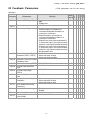
Chapter 4 Parameter Settings|DD Series
07 Control Parameters
Explanation
Settings
Factory
Setting
VF
VFP
SVC
FOC
FOC
Parameter
This parameter can be set during operation.
1.5
○ ○ ○ ○ ○
07.00 ASR (Auto Speed
Regulation) Control (P) of
Zero Speed
0.0~500.0%
07.01 ASR (Auto Speed
Regulation) Control (I) of
Zero Speed
0.000~10.000sec
07.02 ASR (Auto Speed
Regulation) Control (P) 1
0.0~500.0%
07.03 ASR (Auto Speed
Regulation) Control (I) 1
0.000~10.000sec
07.04 ASR (Auto Speed
Regulation) Control (P) 2
0.0~500.0%
07.05 ASR (Auto Speed
Regulation) Control (I) 2
0.000~10.000sec
0.100 ○ ○ ○ ○ ○
07.06 ASR 1/ASR2 Switch
Frequency
0.00~120.00Hz (0:Disable)
2.00 ○ ○ ○ ○ ○
07.07 ASR Primary Low Pass
Filter Gain
0.000~0.350sec
0.008 ○ ○ ○ ○ ○
07.08 Zero Speed/ASR1 Width
Adjustment
0.00~120.00Hz
2.00
○
○ ○
07.09 ASR1/ASR2 Width
Adjustment
0.00~120.00Hz
5.00
○
○ ○
07.10
Mechanical Gear Ratio
1~100
07.11
Inertia Ratio
07.12
0.050 ○ ○ ○ ○ ○
1.5
○ ○ ○ ○ ○
0.050 ○ ○ ○ ○ ○
3.0
○ ○ ○ ○ ○
1
○ ○
1~300%
100
○ ○
Zero-speed Bandwidth
0~40Hz
20
○ ○
07.13
Low-speed Bandwidth
0~40Hz
20
○ ○
07.14
High-speed Bandwidth
0~40Hz
20
○ ○
07.15
PDFF Gain Value
0~200%
0
○ ○
07.16
Gain for Speed Feed
Forward
0~500
0
○ ○
4-18
Chapter 4 Parameter Settings|DD Series
08 Multi-step Speed Parameter
Explanation
Settings
Factory
Setting
VF
VFP
SVC
FOC
FOC
Parameter
This parameter can be set during operation.
0.00~120.00Hz
0.00 ○ ○ ○ ○ ○
08.01 1st Step Speed Frequency 0.00~120.00Hz
08.02 2nd Step Speed Frequency 0.00~120.00Hz
0.00 ○ ○ ○ ○ ○
08.03 3rd Step Speed Frequency 0.00~120.00Hz
08.04 4th Step Speed Frequency 0.00~120.00Hz
0.00 ○ ○ ○ ○ ○
08.05 5th Step Speed Frequency 0.00~120.00Hz
08.06 6th Step Speed Frequency 0.00~120.00Hz
0.00 ○ ○ ○ ○ ○
08.07 7th Step Speed Frequency 0.00~120.00Hz
08.08 8th Step Speed Frequency 0.00~120.00Hz
0.00 ○ ○ ○ ○ ○
08.09 9th Step Speed Frequency 0.00~120.00Hz
0.00~120.00Hz
08.10 10th Step Speed
Frequency
08.11 11th Step Speed Frequency 0.00~120.00Hz
0.00 ○ ○ ○ ○ ○
08.12 12th Step Speed
Frequency
0.00~120.00Hz
0.00 ○ ○ ○ ○ ○
08.13 13th Step Speed
Frequency
0.00~120.00Hz
0.00 ○ ○ ○ ○ ○
08.14 14th Step Speed
Frequency
0.00~120.00Hz
0.00 ○ ○ ○ ○ ○
08.15 15th Step Speed
Frequency
0.00~120.00Hz
0.00 ○ ○ ○ ○ ○
08.00 Zero Step Speed
Frequency
4-19
0.00 ○ ○ ○ ○ ○
0.00 ○ ○ ○ ○ ○
0.00 ○ ○ ○ ○ ○
0.00 ○ ○ ○ ○ ○
0.00 ○ ○ ○ ○ ○
0.00 ○ ○ ○ ○ ○
Chapter 4 Parameter Settings|DD Series
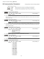
09 Communication Parameters
Explanation
Settings
09.00 Communication Address
01~254
09.01 Transmission Speed
4.8~115.2Kbps
09.02 Transmission Fault
Treatment
0: Warn and keep operation
1: Warn and ramp to stop
2: Reserved
3: No action and no display
0.0~100.0sec
09.03 Time-out Detection
09.04 Communication Protocol
09.05 Response Delay Time
0: 7N1 (ASCII)
1: 7N2 (ASCII)
2: 7E1 (ASCII)
3: 7O1 (ASCII)
4: 7E2 (ASCII)
5: 7O2 (ASCII)
6: 8N1 (ASCII)
7: 8N2 (ASCII)
8: 8E1 (ASCII)
9: 8O1 (ASCII)
10: 8E2 (ASCII)
11: 8O2 (ASCII)
12: 8N1 (RTU)
13: 8N2 (RTU)
14: 8E1 (RTU)
15: 8O1 (RTU)
16: 8E2 (RTU)
17: 8O2 (RTU)
0.0~200.0ms
4-20
Factory
Setting
VF
VFP
SVC
FOC
FOC
Parameter
This parameter can be set during operation.
1
○ ○ ○ ○ ○
19.2 ○ ○ ○ ○ ○
3
○ ○ ○ ○ ○
0.0
○ ○ ○ ○ ○
13
○ ○ ○ ○ ○
2.0
○ ○ ○ ○ ○
Chapter 4 Parameter Settings|DD Series
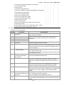
10 User-defined Parameters
This parameter can be set during operation.
Parameter
Explanation
Settings
10.00 Start-up Display Selection
0003
10.01 Maximum Operation
Frequency
0131
10.02 Motor Rated Frequency
0132
10.03 Motor Rated Voltage
0133
10.04 2nd Output Frequency
(Mid-point frequency)
0134
10.05 2nd Output Voltage
(Mid-point voltage)
0135
10.06 3rd Output Frequency
(Mid-point frequency)
0136
0402
10.16 Door Open by Initial Speed
0400
1017 Door Open High Speed
0403
10.18 Door Open Final Speed
0405
10.19 Door Open Holding Torque
Level
0410
10.20 Door Open Holding Torque
0411
10.21 Door Close High Speed
0503
10.22 Door Close Final Speed
0505
Read
only
Read
only
Read
only
Read
only
Read
only
○ ○ ○ ○ ○
○ ○ ○ ○ ○
○ ○ ○ ○ ○
○ ○ ○ ○ ○
○ ○ ○ ○ ○
Read ○
only
Read ○
only
Read ○
only
Read ○
only
Read ○
only
Read ○
only
Read ○
only
Read ○
only
Read ○
only
Read ○
only
Read ○
only
Read ○
only
Read ○
only
Read ○
only
Read ○
only
Read ○
only
Read ○
only
Read ○
only
10.07 3rd Output Voltage (Mid-point 0137
voltage)
10.08 4th Output Frequency (Low 0138
Frequency)
0139
10.09 4th Output Voltage (Low
Voltage)
10.10 Door Open Acceleration Time 0408
1
0409
10.11 Door Open Deceleration
Time 1
0508
10.12 Door Close Acceleration
Time 2
0509
10.13 Door Close Deceleration
Time 2
0015
10.14 Frequency Testing
10.15 Door Open Time by Initial
Speed
Factory
Setting
VF
VFP
SVC
FOC
FOC
Group 10 shows the explanation for the “User-defined Parameters” from Group 00~09
4-21
○ ○ ○ ○
○ ○ ○ ○
○ ○ ○ ○
○ ○ ○ ○
○ ○ ○ ○
○ ○ ○ ○
○ ○ ○ ○
○ ○ ○ ○
○ ○ ○ ○
○ ○ ○ ○
○ ○ ○ ○
○ ○ ○ ○
○ ○ ○ ○
○ ○ ○ ○
○ ○ ○ ○
○ ○ ○ ○
○ ○ ○ ○
○ ○ ○ ○
Parameter
Explanation
Settings
10.23 Door Close Holding Torque
Level
0510
10.24 Door Close Holding Torque
0511
10.25 Multi-function Input Terminal 0207
Direction
0201
10.26 Multi-function Input 1
10.27 Multi-function Input 2
0202
10.28 Multi-function Input 3
0203
10.29 Multi-function Input 4
0204
10.30 Multi-function Output RY1
0208
10.31 Multi-function Output RY2
0209
4-22
Factory
Setting
VF
VFP
SVC
FOC
FOC
Chapter 4 Parameter Settings|DD Series
Read
only
Read
only
Read
only
Read
only
Read
only
Read
only
Read
only
Read
only
Read
only
○ ○ ○ ○ ○
○ ○ ○ ○ ○
○ ○ ○ ○ ○
○ ○ ○ ○ ○
○ ○ ○ ○ ○
○ ○ ○ ○ ○
○ ○ ○ ○ ○
○ ○ ○ ○ ○
○ ○ ○ ○ ○
Chapter 4 Parameter Settings|DD Series
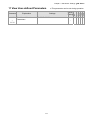
11 View User-defined Parameters
11.00
~
11.31
Explanation
View User-defined
Parameters
Settings
Factory
Setting
Pr. 00.00~09.05
○ ○ ○ ○ ○
-
4-23
VF
VFP
SVC
FOC
FOC
Parameter
This parameter can be set during operation.
Chapter 4 Parameter Settings|DD Series
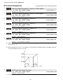
4-2 Description of Parameter Settings
00 System Parameter
This parameter can be set during operation.
Identity Code of AC Motor Drive
Control mode
VF
VFPG
Settings
SVC
FOCPG FOCPM
Factory setting: Read only
0:200w
1:400w
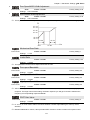
Rated Current Display of AC Motor Drive
Control mode
VF
VFPG
Settings
SVC
FOCPG FOCPM
Factory setting: Read only
0:1.50A
2:2.50A
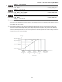
Pr. 00-00 displays the identity code of the AC motor drive. The capacity, rated current, rated voltage and
the max. carrier frequency relate to the identity code. Users can use the following table to check how the
rated current, rated voltage and max. carrier frequency of the AC motor drive corresponds to the identity
code.
Pr.00-01 displays the rated current of the AC motor drive. By reading this parameter the user can check if
the AC motor drive is correct.
Parameter Reset
Control mode
VF
VFPG
Settings
SVC
FOCPG FOCPM
Factory setting: 0
0: No function
1: Parameters locked
8: Keypad locked
10: All parameters are reset to factory setting (33.3Hz, 230V)
When it is set to 1, all parameters are read only except Pr.00-00~00-07 and it can be used with password
setting for password protection.
When Pr.00-02=10, all parameters are reset to factory setting. If password lock was used, please unlock
first. After Pr.00-02 set to 10, password will also be cleared and reset to factory setting.
When Pr.00-02=08, the digital keypad will be locked and only Pr.00-02, Pr.00-07 can be set.
Start-up Display Selection
Control mode
VF
VFPG
Settings
SVC
FOCPG FOCPM
Factory setting: 0
0: Display the frequency command value (F)
1: Display the actual output frequency (H)
2: Display the content of user-defined unit (U)
3: Display the output current (A)
This parameter determines the start-up display page after power is applied to the drive.
Content of Multi Function Display
Control mode
VF
VFPG
Settings
SVC
FOCPG FOCPM
0: Display output current (A )
1: Display actual frequency (Hz)
2: Display DC-BUS voltage ( U)
3: Display output voltage( E )
4: Display power factor angle (n.)
4-24
Factory setting: 2
Chapter 4 Parameter Settings|DD Series
5: Display output power (kW)
6: Display motor angle speed (HU)
7: Display the drive’s estimated output torque (kg-m)
8: Display PG pulse input position
9: Display the electrical angle
10: Display IGBT temperature(oC)
11: Display digital input ON/OFF status
12: Display digital output ON/OFF status
13: Display current multi-step speed
14: Display the corresponding CPU pin status of digital input
15: Display the corresponding CPU pin status of digital input
16:Actual output voltage when malfunction
17: Actual DC-BUS voltage when malfunction
18: Actual output frequency when malfunction
19: Actual output current when malfunction
20: Actual frequency command when malfunction
21: Door width in % or step speed
22: Door width(pulse)
23: Over modulation indication
※Description to function 08
[( rpm XPPR)/1000]X10= Pulse/10ms
60
rpm=motor speed; PPR= (Encoder) pulse number per turn; 1000 (1sec= 1000ms); 10: encoder pulses
per10ms
On this page, press
to display the content of Pr.00.04 (setting 0~23) accordingly.
Software version
Control mode
VF
VFPG
Settings
SVC
FOCPG FOCPM
Factory setting: #. ##
Read only (Different versions will display differently)
Password Input
Control mode
VF
VFPG
Settings
SVC
FOCPG FOCPM
Factory setting: 0
0~9999
0~2:times of wrong password
Password Set
Control mode
VF VFPG SVC FOCPG FOCPM
Settings 0~9999
0: No password set or successful input in Pr.00-06
Factory setting: 0
1: Password has been set
The function of this parameter is to input the password that is set in Pr.0-07. Input the correct password
here to enable changing parameters. You are limited to a maximum of 3 attempts. After 3 consecutive
failed attempts, a blinking “PcdE” will show up to force the user to restart the AC motor drive in order to
try again to input the correct password.
To set a password to protect your parameter settings.
If the display shows 00, no password is set or password has been correctly entered in Pr.0-06. All
parameters can then be changed, including Pr.0-07.
The first time you can set a password directly. After successful setting of password the display will show
01.
Be sure to record the password for later use.
To cancel the parameter lock, set the parameter to 00 after inputting correct password into Pr. 0-07.
4-25
Chapter 4 Parameter Settings|DD Series
The password consists of min. 1 digit and max. 4 digits.
How to make the password valid again after decoding by Pr.0-07:
Method 1: Re-input original password into Pr.0-07 (Or you can enter a new password if you want to
use a new one).
Method 2: After rebooting, password function will be recovered
Method 3: Input any number or character in Pr.00-07, but not password. (The display screen will show
END whether the password entered in Pr.00-07 is accurate or not.)
Password Decode Flow Chart
0-06
0-07
Displays 00 when
entering correct
password into
Pr.0-07.
Correct Password
END
Incorrect Password
END
0-07
0-06
Displays 00 when
entering correct
password into
Pr.0-07.
3 chances to enter the correct
password.
1st time displays "01" if
password is incorrect.
2nd time displays "02", if
password is incorrect.
3rd time displays "Pcde"
(blinking)
If the password was entered
incorrectly after three tries,
the keypad will be locked.
Turn the power OFF/ON to
re-enter the password.
Control Method
Control mode
VF
VFPG
Settings
SVC
FOCPG FOCPM
Factory setting: 0
0: V/f control
1: V/f Control + Encoder (VFPG)
2: Sensorless vector control (SVC)
3: FOC vector control + Encoder (FOCPG)
8: FOC PM control (FOCPM)
This parameter is used to select the control mode of AC motor drives.
0: V/f control: user can design proportion of V/f as required and can control multiple motors
simultaneously.
1: V/f control + Encoder (VFPG): user can use optional PG card with encoder for the closed-loop speed
control.
2: Sensorless vector control (SVC): get the optimal control by the auto-tuning of motor parameters.
3: FOC vector control+ encoder (FOCPG): besides torque increases, the speed control will be more
accurate (1:1000).
4: FOC PM control + encoder (FOCPM): besides torque increases, the speed control will be more
4-26
Chapter 4 Parameter Settings|DD Series
accurate (1:1000).
Door Control Mode
Control mode
VF
VFPG
SVC
Factory setting: 3
FOCPG FOCPM
0: Distance control mode
1: Reserved
2: Multi-step speed control mode
Settings
3: Speed control mode
0: Distance control mode
Set encoder PG pulses accurately to ensure precise door width estimation. Door width is measured and
stored by Auto-tuning. It operates the door for speed switch and completed position by counting the PG
pulses. In this mode, position function will be executed whenever power again and operates with low
speed to the 0% or 100% door width by the operation direction.
O pen Door (R EV)
04.03
Door Open
by Ini tial
Speed
04.00
Door Open H igh Speed 1
04.08
Door Open
Acceleration
Time 1
04.09
Door Open
Deceleration
Time 1
Door Close Limit
0.0%
05.09
05.05
Door Close
Final Speed
05.06
Door Close
with Hol ding
Speed Start
Door Close
Final Speed
05.03
Door Close
High Speed 1
05.04
Door Close
Final Speed
Start
Door Open
Holding Speed
04.07
04.06
Door Open
04.04
Door Open
by Holding
Speed Start
by Final Speed
Start
05.08
05.00
D oor Clos e
Door Close
Acc el er ation Time 1
Ini tial Speed
04.01
Door Open D istanc e
by Ini tial Speed
05.07
Door Close
Holding Speed
Door Open
Final Speed
04.05
05.01
Door Close
Dis tance by
Ini tial Speed
Door Open Limi t
100. 0%
Clos e Door (FWD)
2: Multi-step control mode
The drive is controlled by Sensorless control. For operating the door, it uses three multi-input (level
trigger) and operation direction (FWD/REV) to deal with speed switch and limit switch to deal with
completed position. (4th logic signal: open: 0; close: 1).
4-27
Chapter 4 Parameter Settings|DD Series
Open Door (REV)
08. 08
8th Step
Speed
08. 02
2nd Step
Speed
08. 01
1st Step
Speed
08. 00
Zero Step
Speed
08. 09
9th Step
Speed
08. 03
3rd St ep
Speed
08. 10
10t h Step
Speed
Close Door Limit
08. 11
11t h Step
Speed
08. 04
4th Step
Speed
08. 05
5th Step
Speed
08. 13
13t h Step
Speed
08. 12
12t h Step
Speed
08. 06
6th Step
Speed
08. 07
7th Step
Speed
08. 15
15t h Step
Speed
08. 14
14t h Step
Speed
Open Door Limit
Close Door (FWD)
3: Speed Control mode
For operating the door, it switches speed by external signal and uses limit switch to deal with completed
position. The signals must be edge trigger. In this mode, it needs to run the door to the close complete
position after power on again or AC motor drive stops.
Open Door (R EV)
04.03 Door Open H igh Speed 1
Door Open
by I ni tial
Speed
04.00
04.09
Door Open
Decelerat ion
Time 1
04.08
Door Open
Accelerat ion
Time 1
04.02
Door Open T ime by
Ini tial Speed
05.07
Door Close
Holding Speed
Door Close Limit
0.0%
Door Open
Speed Sw itc h
Signal
05.05
Door Close
Final Speed
Door Close
Limit Signal
Door Open
Final Speed
04.05
05. 03
Door Close
High Speed 1
Door Close
Speed Sw itc h
Signal
Door Open
Limit Signal
05.08
D oor Clos e
Acc el er at ion Time 1
05.09
Door C lose
Final Speed
Door Open
Holding Speed
04.07
05.00
Door Close
Ini tial Speed
05.01
Door Close
Dis tance by
Ini tial Speed
Door Open Limi t
100. 0%
Clos e Door (FWD)
Output Direction
Control mode
VF
VFPG
Settings
SVC
FOCPG FOCPM
Factory setting: 0
0: Runs in same direction as setting
1: Runs in different direction than setting
PWM Carrier Frequency Selection
Control mode
VF
VFPG
Settings
SVC
FOCPG FOCPM
2~15kHz
4-28
Factory setting: 10
Chapter 4 Parameter Settings|DD Series
This parameter determines the PWM carrier frequency of the AC motor drive.
Carrier
Frequency
Acoustic
Noise
1kHz
Significant
Electromagnetic
Noise or leakage
current
Minimal
Heat
Dissipation
Current
Wave
Minimal
Minimal
Significant
Significant
8kHz
15kHz
Minimal
Significant
From the table, we see that the PWM carrier frequency has a significant influence on the
electromagnetic noise, AC motor drive heat dissipation, and motor acoustic noise. If noises from
ambient environment is greater than motor noise, lower PWM carrier frequency will help to lower the
temperature of AC motor drive. When PWM carrier frequency is high, though the drive will operate more
quietly, but wiring and interference may have problem.
Model VFDXXXDDXXE: Settings 02~10kHz
Auto Voltage Regulation (AVR) Function
Control mode
VF
VFPG
Settings
SVC
FOCPG FOCPM
Factory setting: 0
0: Enable AVR
1: Disable AVR
2: Disable AVR when deceleration stop
The rated voltage of the motor is usually AC220V/200V 60Hz/50Hz and the input voltage of the AC motor
drive may vary between 180V to 264 VAC 50Hz/60Hz. Therefore, when the AC motor drive is used
without AVR function, the output voltage will be the same as the input voltage. When the motor runs at
voltages exceeding the rated voltage with 12% - 20%, its lifetime will be shorter and it can be damaged
due to higher temperature, failing insulation and unstable torque output.
AVR function automatically regulates the AC motor drive output voltage to the Maximum Output Voltage
(Pr.1-02). For instance, if Pr.1-02 is set at 200 VAC and the input voltage is at 200V to 264VAC, then the
Maximum Output Voltage will automatically be reduced to a maximum of 200 VAC.
When motor stops with deceleration, it will shorten deceleration time. When setting this parameter to 02
with auto acceleration/deceleration, it will offer a quicker deceleration.
Source of the Master Frequency Command
Control mode
VF
VFPG
Settings
SVC
FOCPG FOCPM
Factory setting: 1
0: by digital keypad input
1: by external terminal
2: by RS-485 serial communication
This parameter is used to set the source of the operation command.
Demo Mode
Control mode
VF
VFPG
Settings
SVC
FOCPG FOCPM
Factory setting: 0
0: Disable
1: Display demo action
Frequency Testing Command
Control mode
VF
VFPG
Settings
SVC
FOCPG FOCPM
0~120.00Hz
4-29
Factory setting: 0
Chapter 4 Parameter Settings|DD Series
When Pr.00-15 is not 0, door will move in testing frequency, other commands to door will stop.
4-30
Chapter 4 Parameter Settings|DD Series
01 Motor Parameters
This parameter can be set during operation.
Motor Auto Tuning (PM)
Control mode
FOCPM
Settings
Factory setting: 0
0: No function
1: Auto-tuning for PM motor parameters (brake locked)
2: Auto-tuning for PG offset angle without load (Pr.01.09)
3: Auto-tuning for PG offset angle with load (Pr.01.09)
When Pr.01-00 = 2, auto-tune for PG offset angle. Please follow the following 3 rules:
1. Unload before Auto-tuning begins.
2. If the brake is control by AC motor drive, the drive can complete tuning process after wiring
and brake control parameters are set.
3. If the brake is control by host controller, maker sure brake is at release status when tuning.
When Pr.01-00=3, auto-tuning for PG offset angle. Please follow the following 3 rules:
1. Tuning with load or unload are both allow.
2. When the brake is control by the AC motor drive, after wiring and braking parameters are
set up, the drive will execute Tuning following the settings.
3. When the brake is control by the host controller, make sure the brake is released before
execute Tuning.
4. Make sure Pr.03-02 (Encoder Input Type) is correct; a wrong setting would cause Pr.01-09
(PG offset angle) measurement error.
When Pr.01-00=1, begins auto-tuning for PM motor by press the【Run】key. After auto-tuning process is
completed, the measured value will automatically be written into Pr. 01.05, Pr.01.07 (Rs、Lq) and
Pr.01.08 (Back EMF).
AUTO-Tuning Process (static rolling) :
1. Make sure the drive is properly installed and all parameter settings are set to the factory
setting.
2. Motor: input accurate motor value into Pr.01.01, 01.02, 01.03, 01.04 and adjust the accel.
/decel. time according to your motor capacity.
3. Set Pr.01-00=1 and press the “RUN” key on the digital keypad. The motor should now
begin auto-tuning. (Note: It is important to fix the motor stably to prevent shaking.)
4. When auto-tuning is complete, check if measured values are written into Pr.01.05 and
01.07.
NOTE
;
The input rated speed can not be greater than or equal to 120f/p.
;
When auto-tuning is in process, an “Auto-tuning” message will show on the digital keypad. Once the process is complete,
the “Auto-tuning” message will be cleared and the measured values will be written into Pr.01-09.
;
When auto-tuning is in process, if an error occurs or the drive is stopped manually, an “Auto Tuning Err” message will
appear on the digital keypad and it indicates auto-tuning failure, please check if the wirings of the drive are proper. When
“PG Fbk Error” occurs, please reset Pr.03-02 (if it is originally set to 1, change it to 2). When “PG Fbk Loss” occurs, please
check if the Z phase pulse feedback is normal.
4-31
Chapter 4 Parameter Settings|DD Series
Full-load Current of motor (PM)
Control mode
Unit: Amper
FOCPM
Settings
Factory setting: 1.00
(20~120%)*00.01 Amps
This value should be set according to the rated frequency of the motor as indicated on the motor
nameplate. The factory setting is 90% X rated current.
Example: If rated current for 400W model is 2.5A. The current range for user will be 0.5~3.0A.
(2.5*20%=0.5; 2.5*120%=3.0)
Rated Power of Motor (PM)
Control mode
Factory setting: 0.06
FOCPM
Settings
0.00~655.35 kW
This parameter sets motor’s rated power. Factory setting will be the drive’s power.
Rated Speed of PM Motor (rpm)
Control mode
FOCPM
Settings
Factory setting: 250
0~65535
This parameter sets motor’s rated speed and it must be set according to the specification shown on the
nameplate.
Number of Motor Poles (PM)
Control mode
FOCPM
Settings
Factory setting: 16
2~96
This parameter sets number of motor poles (odd value is invalid).
Rs of Motor parameter (PM)
Control mode
FOCPM
Settings
Factory setting: 13.900
0.0~655.35Ω
Ld of Motor Parameter (PM)
Control mode
FOCPM
Settings
Factory setting: 169.4
0.0~6553.5mH
Lq of Motor Parameter (PM)
Control mode
FOCPM
Settings
Factory setting: 169.4
0.0~6553.5mH
Back Electromotive Force (PM)
Control mode
FOCPM
Settings
Factory setting: 0.0
0.0~6553.5Vrms
This parameter is used to set back electromotive force (phase-phase RMS value) when the motor is
operated in the rated speed.
It can get RMS value by Pr.01-00=1 (Motor Auto Tuning)
PG Offset Angle (PM)
Control mode
FOCPM
Settings
0.0~360.0°
This parameter is to measure the PG offset angle of PM motor.
4-32
Factory setting: 360.0
Chapter 4 Parameter Settings|DD Series
Magnetic Pole Re-orientation (PM)
Control mode
Factory setting: 0
FOCPM
Settings
0:No function
1:Reset magnetic pole position
This function is used to search magnetic pole position and is only available on permanent magnet motor.
When encoder origin-adjustment function (Pr.01-09= 360.0) is not available, the motor operation efficiency
can only achieve up to 86% of its best efficiency. In this case, if user needs to improve the operation
efficiency, reapply power or set Pr.01-10=1 to measure magnetic pole position again.
Motor Auto Tuning (IM)
Control mode
SVC
Settings
Factory setting: 0
FOCPG
0: No function
1: Rolling test
2: Static test
3: Reserved
Set Pr.01-11 to 1 or 2, Press 【Run】to begin auto tuning. The measured value will be written into Pr.1-17
to Pr.01-20 (Rs, Rr, Lm, Lx, no-load current).
AUTO-Tuning Process (rolling test):
1.
2.
Make sure that all the parameters are set to factory settings and the motor wiring is correct.
Make sure the motor has no-load before executing auto-tuning and the shaft is not connected to any
belt or gear motor. It is recommended to perform auto-tuning in static test if the motor can’t separate
from the load.
3.
Pr. of Motor
Motor Rated
01-32
Frequency
Motor Rated
01-33
Voltage
Motor Full-load
01-12
Current
Motor Rated
01-13
Power
Motor Rated
01-14
Speed
Motor Pole
01-15
Numbers
Set Pr.01-11=1 and press【Run】, the drive will begin auto-tuning. Please be aware of the motor that
it starts spinning as【Run】 is pressed.
When auto-tuning is completed, please check if the measured values are written into Pr.01-16
~01-20).
Mechanical equivalent circuit
4.
5.
6.
I
Rs
Pr.0 1-17
Lx
Pr.0 1-20
Lm
VS
Pr.0 1-19
Rr
Pr.0 1-18
※ When Pr.01-11 is set to 2 (static test), user needs to write no-load current value of motor into
Pr.01-16.
4-33
Chapter 4 Parameter Settings|DD Series
NOTE
;
In torque/vector control mode, it is not recommended to have motors run in parallel.
;
It is not recommended to use torque/vector control mode if motor rated power exceeds the
rated power of the AC motor drive.
;
The no-load current is usually 20~50% X rated current.
;
The rated speed can not be greater than or equal to 120f/p (f=rated frequency Pr.01-32; P:
number of motor poles Pr.01-15).
Full-load Current of Motor (IM)
Control mode
VF
VFPG
Settings
SVC
Unit: Amper
Factory setting: 1.00
FOCPG
(20~120%)*00.01 Amps
This value should be set according to the rated frequency of the motor as indicated on the motor
nameplate. The factory setting is 90% X rated current.
Example: If rated current for 400W model is 2.5A. The current range for user will be 0.5~3.0A.
(2.5*20%=0.5
2.5*120%=3.0)
Rated power of Motor (IM)
Control mode
SVC
Settings
Factory setting: 0.06
FOCPG
0.00~655.35 kW
This parameter sets motor’s rated power. Factory setting will be the drive’s power.
Rated speed of IM Motor (rpm)
Control mode
VFPG
Settings
SVC
Factory setting: 250
FOCPG
0~65535
This parameter sets motor’s rated speed and it must be set according to the specification shown on the
nameplate.
Number of Motor Poles (IM)
Control mode
VF
VFPG
Settings
SVC
Factory setting: 16
FOCPG
2~96
This parameter sets number of motor poles (odd value is invalid).
No-load Current of Motor (IM)
Control mode
VFPG
Settings
SVC
Factory setting: #. ##
FOCPG
00~ Pr.01.12 factory setting
Factory setting of the drive’s rated current is 40%.
Rs of Motor (IM)
Control mode
SVC
Settings
Factory setting: 0.000
FOCPG
0.000~65.535Ω
Rr of Motor (IM)
Control mode
SVC
Settings
Factory setting: 0.000
FOCPG
0.0~65.535Ω
Lm of Motor (IM)
Control mode
SVC
Settings
Factory setting: 0.0
FOCPG
0.0~6553.5mH
Lx of Motor (IM)
Control mode
SVC
Factory setting: 0.0
FOCPG
4-34
Chapter 4 Parameter Settings|DD Series
Settings
0.0~6553.5mH
Torque Compensation Time Constant
Control mode
Factory setting: 0.020
SVC
Settings
0.001~10.000sec
Slip Compensation Time Constant
Control mode
Factory setting: 0.100
SVC
Settings
0.001~10.000sec
The slip compensation response time can be set by Pr.01-21 and Pr.01-22 and maximum up to 10 sec.
When Pr.01-21 and Pr.01-22 are set to 10 sec, it is the slowest response time the drive supports. If the
response time is set too quick, the system may be unstable.
Torque Compensation Gain
Control mode
VF
Factory setting: 0
VFPG
Settings
0~10
This parameter sets the amount of additional voltage output during operation to get greater torque.
Slip Compensation Gain
Control mode
VF
VFPG
Settings
Factory setting: 0.00
SVC
0.00~10.00
When AC motor drive drives the induction motor, slips increase as load increase. This parameter can be
used to set compensation frequency and reduce the slip to close the synchronous speed when the motor
runs in the rated current to raise the drive accuracy. When drive’s output current is greater than the motor
current at no-load, the drive will compensate the frequency according to the setting in this parameter.
When actual speed is slower than expected, increase the value in Pr.01-24; if actual speed is faster than
expected, lower the value in Pr.01-24.
This parameter is valid for SVC mode only.
Slip Deviation Level
Control mode
VFPG
Settings
SVC
Factory setting: 0
FOCPG
00~1000% (0:Disable)
Detection Time of Slip Deviation
Control mode
VFPG
Settings
SVC
Factory setting: 1.0
FOCPG
0.0~10.0sec
Over Slip Treatment
Control mode
VFPG
Settings
SVC
Factory setting: 0
FOCPG
0: Warn and keep operation
1: Warn and ramp to stop
2: Warn and coast to stop
Pr.01-25 to Pr.01-27 is used to set the allowable slip level/time and over slip treatment when the drive is
running.
Hunting Gain
Control mode
VF
VFPG
Factory setting: 2000
SVC
4-35
Chapter 4 Parameter Settings|DD Series
Settings
0~10000 (0: No action)
The motor will have current wave motion in some specific area. It can improve this situation by setting
this parameter. (When it is high frequency or run with PG, it can be set to 0. when the current wave
motion happens in the low frequency, please increase the value in Pr.01-28.)
Accumulative Motor Operation Time (Min.)
Control mode
VF
VFPG
Settings
SVC
Factory setting: 0
FOCPG
0~1439
Accumulative Motor Operation Time (day)
Control mode
VF
VFPG
Settings
SVC
Factory setting: 0
FOCPG
0~65535
This parameter records the motor running time. When Pr.01-29 and Pr.01-30 are set to 00, it clears the
setting to 0. Operation time will not be recorded if it is shorter than 60 sec.
Maximum Output Frequency
Control mode
VF
VFPG
Settings
SVC
FOCPG FOCPM
Factory setting: 50
10.00~120.00Hz
This parameter determines the AC motor drive’s Maximum Output Frequency. All the AC motor drive
frequency command sources (analog inputs 0 to +10V, 4 to 20mA, 0 to 20mAand ±10V) are scaled to
correspond to the output frequency range.
Output Frequency 1(Base frequency /Motor rated frequency)
Control mode
VF
VFPG
Settings
SVC
FOCPG FOCPM
Factory setting: 50
0.00~120.00Hz
This value should be set according to the rated frequency of the motor as indicated on the motor
nameplate. If the motor is 60Hz, the setting should be 60Hz. If the motor is 50Hz, it should be set to
50Hz.
Output Voltage 1(Base voltage/Motor rated voltage)
Control mode
VF
VFPG
Settings
SVC
FOCPG FOCPM
Factory setting: 220.0
0.0V~240.0V
This value should be set according to the rated voltage of the motor as indicated on the motor nameplate.
If the motor is 220V, the setting should be 220.0. If the motor is 200V, it should be set to 200.0.
There are many motor types in the market and the power system for each country is also difference. The
economic and convenience method to solve this problem is to install the AC motor drive. There is no
problem to use with the different voltage and frequency and also can amplify the original characteristic
and life of the motor.
Output Frequency 2
Control mode
VF
Factory setting: 0.50
VFPG
Settings
0.00~120.00Hz
Output Voltage 2
Control mode
VF
Factory setting: 5.0
VFPG
Settings
0.0V~240.0V
Output Frequency 3
Control mode
VF
Factory setting: 0.50
VFPG
4-36
Chapter 4 Parameter Settings|DD Series
Settings
0.00~120.00Hz
Output Voltage 3
Control mode
VF
Factory setting: 5.0
VFPG
Settings
0.0V~240.0V
Output Frequency 4
Control mode
VF
VFPG
Settings
SVC
Factory setting: 0.00
FOCPG
0.00~120.00Hz
Output Voltage 4
Control mode
VF
Factory setting: 0.0
VFPG
Settings
0.0V~240.0V
V/f curve setting is usually set by the motor’s allowable loading characteristics. Pay special attention to
the motor’s heat dissipation, dynamic balance, and bearing lubricity, if the loading characteristics exceed
the loading limit of the motor.
The frequency setting of V/F curve must be set according to this rule, Pr. 01.32≥01.34≥01.36≥01.38.
There is no limit for the voltage setting, but a high voltage at low frequency may cause motor damage,
overheat, and stall prevention or over-current protection. Therefore, please use the low voltage at the low
frequency to prevent motor damage.
Vo lt age
Out put Volta ge 1
0 1.33
Fre quency Ou tpu t
Limit
Out put Volta ge 2
0 1.35
Out put Volta ge 3
0 1.37
Out put Volta ge 4
0 1.39
01. 38
O utp ut
Fre quen cy
4
01. 36
O utp ut
Fre quen cy
3
01. 34
01. 32
O utp ut
O utp ut
Fre quen cy Fre quen cy
2
1
V/ F Curve
4-37
Freque ncy
01. 31
Max. Out put
Freque ncy
Chapter 4 Parameter Settings|DD Series
02 Input/Output Parameters
This parameter can be set during operation.
2-wire/3-wire Operation Control
Control mode
VF
VFPG
Settings
SVC
Factory setting: 0
FOCPG FOCPM
0 FWD/STOP
1 FWD/STOP, REV/STOP (Line Start Lockout)
2 RUN/STOP, REV/FWD
3 RUN/STOP, REV/FWD (Line Start Lockout)
When line start lockout is enabled, the drive will not run once applying the power. The Line Start Lockout
feature doesn’t guarantee the motor will never start under this condition. It is possible the motor may be
set in motion by a malfunctioning switch. This parameter sets the drive’s lock when power is applied.
This parameter sets three different control modes by external control:
Pr.02-00
Control Circuits of the External Terminal
Setting: 0, 1
2-wrie operation control (1)
O D/STO P
OD:("OPEN":STOP)
("CLOSE":open the door)
Open the door/STOP
CD/STO P
CD:("OPEN": STOP)
("CLOSE": close the door)
Close the door/STOP
CO M
Setting: 2, 3
2-wrie operation control (1)
Open the door/Close the door
RUN/STOP
OD/CD
RUN/STOP
OD:("OPEN":STOP)
("CLOSE":RUN)
CD:("OPEN": open the door)
("CLOSE": close the door)
COM
Multi-Function Input 1 (MI1)
Factory setting: 14
Multi-Function Input 2 (MI2)
Factory setting: 15
Multi-Function Input 3 (MI3)
Factory setting: 16
Multi-Function Input 4 (MI4)
Factory setting: 17
Multi-Function Input 5 (MI5)
Factory setting: 0
Settings
Control mode
0: No function
1: Multi-step speed command 1
2: Multi-step speed command 2
3: Multi-step speed command 3
4: Multi-step speed command 4
5: Fault reset
6: Low speed operation
7: OD/CD command for low speed operation
4-38
VF VFPGSVC FOCPG FOCPM
○
○
○
○
○
○
○
○
○
○
○
○
○
○
○
○
○
○
○
○
○
○
○
○
○
○
○
○
○
○
○
○
○
○
○
○
○
○
○
○
Chapter 4 Parameter Settings|DD Series
8: 1st, 2nd acceleration/deceleration time selection
9: Force stop (NO) input
10: Demo mode
11: Emergency stop (NO) input
12: Source of operation command (Keypad/External terminals)
13: Parameter lock enable (NC)
14: Door open complete signal
15: Door close complete signal
16: Door open speed switch signal
17: Door close speed switch signal
18: Open allowance signal
19: Screen signal input
20: Door curve signal input for 2nd set door open/close
21: Reset signal input
22: Input system security circuit confirmation signal (DCC)
23: Input enforced door closing signal (NUD)
○
○
○
○
○
○
○
○
○
○
○
○
○
○
○
○
○
○
○
○
○
○
○
○
○
○
○
○
○
○
○
○
○
○
○
○
○
○
○
○
○
○
○
○
○
○
○
○
○
○
○
○
○
○
○
○
○
○
○
○
○
○
○
○
○
○
○
○
○
○
○
○
○
○
○
○
○
○
○
○
This parameter selects the functions for each multi-function terminal.
Summary of Function Settings:
Settings
Functions
Descriptions
Any unused terminals should be programmed to 0 to insure they
have no effect on operation.
0
No function
1
3
Multi-step speed command 1 When door control mode (Pr.00-09)is set 2 (multi-step speed
Multi-step speed command 2 control), these four inputs can be used for 16 step speed
frequencies
Multi-step speed command 3
4
Multi-step speed command 4
5
Fault reset
Reset drive setting after fault is cleared.
Low speed operation
Before using this function, please make sure that AC motor drive is
stop. At this moment, key “STOP” on the digital keypad is still valid.
When this contact is OFF, motor will stop by deceleration time of
low speed operation.
ON: open the door (OD)
OFF: closer the door (CD)
This command will be effective only when external terminal for low
speed operation is active.
When signal is input, the AC motor drive can switch between 1st
and 2nd acceleration/deceleration time
2
6
7
8
OD/CD command for low
speed operation
1st, 2nd
acceleration/deceleration
time selection
Force stop (NO) input
9
10
11
12
13
Demo mode
This parameter has the same function as the “STOP” command
and no error message will be displayed. It does not require a
RESET but a new RUN command is needed for the drive to run
again.
When this setting is enabled, the output frequency of AC motor
drive will run by open/close curve repeatedly till this setting is
disabled. It will get the best open/close curve by this action.
Emergency stop (NO) input When setting to 11, the Multi-Function Input Terminal can be used
to stop the AC motor drive in case of malfunction in the application.
It will display “EF”. Please “RESET” after the fault has been
cleared.
ON: Operation command via Ext. Terminals
Source of operation
command (Keypad/External OFF: Operation command via Keypad
terminals)
Pr.00-14 is disabled if this parameter is set to 13.
Parameter lock enable (NC) When this setting is enabled, all parameter reading value will be
00. This setting must be disabled in order to read the parameter
content.
4-39
Chapter 4 Parameter Settings|DD Series
Door open complete signal When Pr.06-11 is set to 01 or 03, drive will open the door to the
completed position by this signal.
Door close complete signal When Pr.06-11 is set to 02 or 03, drive will close the door to the
completed position by this signal.
Door open speed switch
When door control mode (pr.00-09) is set to 3 speed control mode,
signal
this terminal can be used for switching speed.
Door close speed switch
When door control mode (pr.00-09) is set to 3 speed control mode,
signal
this terminal can be used for switching speed.
Open allowance signal
When this setting is enabled, it allows opening the door. It also can
be used for the signal of door zone.
14
15
16
17
18
19
Screen signal input
Door curve signal input for When this setting is ON, it will run the curve of 2nd step door
2nd step door open/close
open/close.
Reset signal input
When parameter is set to 21, the drive re-positioning begins.
Input system security circuit When the motor drive receives this signal then any door closing
confirmation signal (DCC) signal will not be input. And the door will remain at the actuation
position
Input enforced door closing When the motor drive receives this signal, it will close at low speed
signal (NUD)
(Pr03-10), but does not respond to stop closing door function.
20
21
22
23
Digital Terminal Input Debouncing Time (MD-5-13)
Control mode
VF
VFPG
Settings
SVC
FOCPG FOCPM
Factory setting: 0.005
0.001~30.000sec
This parameter is to delay the signals on digital input terminals. 1 unit is 2.5 msec. The delay time is to
debounce noisy signals that could cause the digital terminals to malfunction but response time maybe a
bit slower.
Digital Input Operation Direction
Control mode
VF
VFPG
Settings
SVC
FOCPG FOCPM
Factory setting: 60
0~65535
This parameter is used to set the input signal level.
bit 0 is CD terminal, bit 1is OD terminal and bit 2~bit 6 areMI1~MI5。
User can change the terminal status ON/OFF by communicating.
For example, MI1 is set to 1 (multi-step speed command 1), MI2 is set to 2 (multi-step speed command
2). Then the forward + 2nd step speed command=1001(binary) =9 (Decimal). Only need to set
Pr.02-07=9 by communication and it can forward with 2nd step speed. It doesn’t need to wire any
multi-function terminal.
bit6
bit5
bit4
bit3
bit2
bit1
bit0
MI5
MI4
MI3
MI2
MI1
OD
CD
Multi-function Output (Relay1)
Factory setting: 16
Multi-function Output (Relay2)
Factory setting: 17
Multi-function Output (MO1)
Factory setting: 0
Multi-function Output (MO2)
Factory setting: 0
4-40
Chapter 4 Parameter Settings|DD Series
Multi-function Output (MO3)
Factory setting: 0
Settings
Control mode
0: No function
1: AC drive in operation
2: Zero speed frequency signal (including STOP)
3: AC drive ready
4: Low voltage warning(Lv)
5: Fault indication
6: Overhead warning (Pr.06.09)
7: Detection of braking resistor action level
8: Warning indication
9: Over voltage warning
10: OD command
11: CD command
12: Demo Indication
13: Demo complete
14: Emergency stop indication
15: Force stop indication
16: Door open complete (limit) signal output
17: Door close complete (limit) signal output
18: Door Close Error
19: Position Complete Signal
20: Position Detection 1(for door close only)
21: Position Detection 2(for door close only)
22: Position Detection 3(for door close only))
23: Position Detection 1(for door open only)
24: Position Detection 2(for door open only)
25: Position Detection 3(for door open only)
26: PG feedback error
27: output signal when unable to open the door
28: over torque (OT1)
VF VFPGSVCFOCPG FOCPM
○
○
○
○
○
○
○
○
○
○
○
○
○
○
○
○
○
○
○
○
○
○
○
○
○
○
○
○
○
○
○
○
○
○
○
○
○
○
○
○
○
○
○
○
○
○
○
○
○
○
○
○
○
○
○
○
○
○
○
○
○
○
○
○
○
○
○
○
○
○
○
○
○
○
○
○
○
○
○
○
○
○
○
○
○
○
○
○
○
○
○
○
○
○
○
○
○
○
○
○
○
○
○
○
○
○
○
○
○
○
○
○
○
○
○
○
○
○
○
○
○
○
○
○
○
○
○
○
○
○
○
○
○
○
○
These parameters can be used for external terminal output
Summary of Function Settings
Settings
Functions
Descriptions
0
No function
MO has no function.
01
AC drive in operation
The drive is ON when it receives voltage or operation command.
2
Zero speed frequency signal Zero speed output signals (including STOP).
(including STOP)
3
AC drive ready
4
Low voltage warning(Lv)
Active when the drive is ON and no abnormality detected or
abnormality is cleared.
Active when the detected input voltage is too low.
5
Fault indication
Active when fault occurs.
8
Overhead warning (Pr.06.09) Active when IGBT or heat sink overheats to prevent OH turn off
the drive. When temperature higher than 85℃= ON, lower than
<80℃= OFF.
Detection of braking resistor Active when drive begins software braking, this signal can be
action level
used as brake module VFDB action signal or indicator.
Warning indication
Active when warning is detected.
9
Over voltage warning
6
7
Active when over-voltage is detected.
4-41
Chapter 4 Parameter Settings|DD Series
10
OD command
Active when the operation direction is door open.
11
CD command
Active when the operation direction is door close.
12
Demo Indication
Active when the drive is in demo mode.
Demo complete
14
Emergency stop indication
Active when each time door open/close is complete in demo
mode (contact closed for 0.5s only).
Active when emergency stop is detected.
15
Force stop indication
Active when force stop is detected.
13
Active when position mode (Pr.06-11) is set to “no door close
limit signal” and the door width is greater than the setting in
Door open complete (limit) Pr.04-06.
signal output
Active when position mode (Pr.06-11) is set to door close limit
signal allow and one of MI (Pr.02-01~02-05) is set to 14.
Door close complete (limit) Active when position mode (Pr.06-11) is set to “no door close
limit signal” and the door width is less than Pr.05-06 setting
signal output
during the door close.
Active when position mode (Pr.06-11) is set to door close limit
signal allow and one of MI (Pr.02-01~02-05) is set to 15.
Door close error
Active when door close error. (Includes door reopen and not
reopen).
Position complete signal
Active when positioning is completed after drive power is on or
PGEr. This function is valid when Pr.00-10=00.
Position Detection 1(for door Active when door close width is lower than Pr.06-14 (valid when
close only)
door close).
16
17
18
19
20
Position Detection 2(for door Active when door close width is lower than Pr.06-15 (valid when
close only)
door close).
21
Position Detection 3(for door
close only))
Position Detection 1(for door
open only)
Position Detection 2(for door
open only)
Position Detection 3(for door
open only)
22
23
24
25
26
Active when door close width is lower than Pr.06-16 (valid when
door close).
Active when door close width is lower than Pr.06-14 (valid when
door open).
Active when door close width is lower than Pr.06-14 (valid when
door open).
Active when door close width is lower than Pr.06-14 (valid when
door open).
PG feedback error
Active when PG feedback signal error is detected
output signal when unable to
open the door
over torque (OT1)
27
28
Digital Output Direction
Control mode
VF
VFPG
Settings
SVC
FOCPG FOCPM
Factory setting: 0
00~65535
This parameter is set via bit setting. If a bit is 1, the corresponding output acts in the opposite way.
Example:
If Pr02-08=1 (operation indication) and Pr.02-13=0, Relay 1 RA-RC is closed when the drive runs and is
open when the drive is stopped.
If Pr02-08=1 and Pr02-13=1, Relay 1 RA-RC is open when the drive runs and is closed when the drive is
stopped.
Position Detection Signal 1
Control mode
VF
VFPG
Settings
SVC
FOCPG FOCPM
0.0~100.0%
Position Detection Signal 2
4-42
Factory setting: 25.0
Chapter 4 Parameter Settings|DD Series
Control mode
VF
VFPG
Settings
SVC
FOCPG FOCPM
Factory setting: 12.5
0.0~100.0%
Position Detection Signal 3
Control mode
VF
VFPG
Settings
SVC
FOCPG FOCPM
Factory setting: 7.5
0.0~100.0%
When Pr.02-12 (multi-function output terminal)are set to 16~18, it will output a signal once the door is in
position that Pr.02-14~02-16 set.
4-43
Chapter 4 Parameter Settings|DD Series
03 Feedback Parameter
This parameter can be set during operation.
Encoder (PG) Signal Type
Control mode
VFPG
Settings
Factory setting: 7
FOCPG FOCPM
0: No function
1: ABZ
7: PWM pulse
Detection of the magnetic pole: Setting 1: The AC motor drive will output short circuit to detect the
position of the magnetic pole. At this moment, the motor will generate a little noise.
Reference table for encoder and tuning
Setting of PG signal type Encoder (PG) Signal type
Pr.01-00=01
Pr.01-00=03
03.00=1
A, B, Z
Motor will run
Motor will run
03.00=7
PWM
Motor will run
Motor will run
Encoder pulse
Control mode
VFPG
Settings
Factory setting: 256
FOCPG FOCPM
1~25000
A Pulse Generator (PG) or encoder is used as a sensor that provides a feedback signal of the motor
speed. This parameter defines the number of pulses for each cycle of the PG control (PPR).
Encoder Input Type Setting
Control mode
VFPG
Settings
Factory setting: 1
FOCPG FOCPM
0: Disable
1: Phase A leads in a forward run command and phase B leads in a reverse run
command
FWD
REV
For war d A
running B
2: Phase B leads in a forward run command and phase A leads in a reverse run
command
FWD
REV
A
For war d
running B
3: Phase A is a pulse input and phase B is a direction input. (low input=reverse
direction, high input=forward direction)
FWD
REV
A
For war d
running B
4: Phase A is a pulse input and phase B is a direction input. (low input=forward
direction, high input=reverse direction)
FWD
A
For war d
running B
5: Single-phase input
For war d
running A
It is helpful for the stable control by inputting correct pulse type.
4-44
REV
Chapter 4 Parameter Settings|DD Series
Encoder Feedback Fault Treatment (PGF1, PGF2)
Control mode
VFPG
Settings
Factory setting: 2
FOCPG
0: Warn and keep operation
1: Warn and ramp to stop
2: Warn and stop operation
Detection Time for Encoder Feedback Fault
Control mode
VFPG
Settings
FOCPG FOCPM
Factory setting: 1.0
0.0~10.0sec
When PG loss, encoder signal error, pulse signal setting error or signal error, if time exceeds the
detection time for encoder feedback fault (Pr.03-04), the PG signal error will occur. Refer to the Pr.03-03
for encoder feedback fault treatment.
Encoder Stall Level (PGF3)
Control mode
VFPG
Settings
SVC
FOCPG FOCPM
Factory setting: 115
0~120% (0: disable)
This parameter determines the maximum encoder feedback signal allowed before a fault occurs. (max.
output frequency Pr.01-31 =100%)
Encoder Stall Detection Time
Control mode
VFPG
Settings
SVC
FOCPG FOCPM
Factory setting: 0.1
0.0~2.0sec
Encoder feedback error (Max. output frequency Pr.01-31=100%)
Encoder Slip Range (PGF4)
Control mode
VFPG
Settings
SVC
FOCPG FOCPM
Factory setting: 50
0~50% (0:disable)
Encoder feedback error (Max. output frequency Pr.01-31=100%)
Encoder Slip Detection Time
Control mode
VFPG
Settings
SVC
FOCPG FOCPM
Factory setting: 0.5
0.0~10.0sec
Encoder feedback error (Max. output frequency Pr.01-31=100%)
Encoder Stall and Slip Error Treatment
Control mode
VFPG
Settings
SVC
Factory setting: 2
FOCPG
Encoder PG signal feedback error (Max. output frequency Pr.01-31=100%)
0: Warn and keep operation
1: Warn and ramp to stop
2: Warn and coast to stop
When the value of (rotation speed – motor frequency) exceeds Pr.03-07 setting, detection time exceeds
Pr.03-08 or motor frequency exceeds Pr.03-05 setting, it will start to accumulate time. If detection time
exceeds Pr.10-06, the encoder feedback signal error will occur. Refer to Pr.03-09 encoder stall and slip
error treatment.
Door Width Auto-tuning Frequency
Control mode
VF
VFPG
Settings
SVC
FOCPG FOCPM
Factory setting: 5.0
0.10~120.00Hz
This parameter is the frequency of motor when using door width auto-tuning function.
Door
Control mode
VF
Width Auto-tuning
VFPG
SVC
FOCPG FOCPM
4-45
Factory setting: 0
Chapter 4 Parameter Settings|DD Series
Settings
0: Disable
1: Enable
The door width will be difference due to its application. For example, the door of the freight elevator is
much wider than passenger elevator. Therefore, it needs to have door width auto tuning function to
measure the correct door width for the correct position and door open/close. This parameter is suitable
for the condition when door control mode is set to distance control mode (Pr.00-10=0).
The procedure for the door width auto-tuning function:
1. Close the door and make sure it reaches its close complete position, and then open the door to
measure the door width and close the door again to double check the door width.
2. After door width auto-tuning is complete, the measured value will write into Pr.03-12 and Pr.03-13
automatically.
to make sure the position
of door close limit
Close door (FWD)
measure door width
Open door (REV)
Close door (FWD)
detect if door width is correct
Door open limit
100.0%
Door close limit
0.0 %
Door Width Pulses (Unit:1)
Control mode
VF
VFPG
Settings
SVC
FOCPG FOCPM
Factory setting: 8800
1~9999
Door Width Pulses (Unit:10000)
Control mode
VF
VFPG
Settings
SVC
FOCPG FOCPM
Factory setting: 0
0~9999 (Unit:10000)
After door width auto tuning (Pr.03-11=1) is completed, door width pulses will write into Pr.03-12 and
Pr.03-13 automatically. User can also manually input door width pulses into Pr.03-12 and Pr.03-13.
4-46
。
Chapter 4 Parameter Settings|DD Series
04 Door Open Parameters
This parameter can be set during operation.
Door Open by Initial Speed
Control mode
VF
VFPG
Settings
SVC
FOCPG FOCPM
Factory setting: 2.00
0.00~120.0Hz
Door Open Distance by Initial Speed
Control mode
VF
VFPG
Settings
SVC
FOCPG FOCPM
Factory setting: 300
0~65535 (pulses number)
Door Open Time by Initial Speed
Control mode
VF
VFPG
Settings
SVC
FOCPG FOCPM
Factory setting: 1.0
0~20.0s
Door Open High Speed 1
Control mode
VF
VFPG
Settings
SVC
FOCPG FOCPM
Factory setting: 15.00
0.00~120.0Hz
Door Open by Final Speed Begins
Control mode
VF
VFPG
Settings
SVC
FOCPG FOCPM
Factory setting: 90.0
0.0~100.0% (Door width setting in %)
Door Open Final Speed
Control mode
VF
VFPG
Settings
SVC
FOCPG FOCPM
Factory setting: 5.00
0.00~120.0Hz
Door Open by Holding Speed Begins
Control mode
VF
VFPG
Settings
SVC
FOCPG FOCPM
Factory setting: 95.0
0.0~100.0% (Door width setting in %)
Door Open Holding Speed
Control mode
VF
VFPG
Settings
SVC
FOCPG FOCPM
Factory setting: 2.00
0.00~120.0Hz
Door Open Acceleration Time 1
Control mode
VF
VFPG
Settings
SVC
FOCPG FOCPM
Factory setting: 1.0
0.1~3600sec
Door Open Deceleration Time 1
Control mode
VF
VFPG
Settings
SVC
FOCPG FOCPM
Factory setting: 1.0
0.1~3600sec
Door Open Holding Torque Level
Control mode
VF
VFPG
Settings
SVC
FOCPG FOCPM
Factory setting: 50.0
0.0~150.0% (AC drive’s rated current)
Door open distance (Pr.04-01) is set in pulses number but when converting into %; it must be smaller
than the setting in Pr.04-04. Door close completely is 0% and door open completely is 100%.
Please refer to the diagram below and adjust door open/close curve to your requirement.
4-47
Chapter 4 Parameter Settings|DD Series
O pen Door (R EV)
04.03 Door Open H igh Speed 1
Door Open
by Ini tial
Speed
04.00
04.08
Door Open
Accelerat ion
Time 1
04.09
Door Open
Deceleration
Time 1
04.06
Door Open
04.04
Door Open
by Holding
Speed Begins
by Final Speed
Begi ns
05.08
05.00
D oor Clos e
Door Close
Acc el er at ion Time 1
I ni tial Speed
04.01
Door Open D istanc e
by I ni tial Speed
05.07
Door Close
Holding Speed
Door Close Limit
0.0%
05.09
05.05
Door Close
Final Speed
05.06
Door Close
by Holding
Speed Begins
Door Close
Final Speed
05.03
Door Close
High Speed 1
05.04
Door Close
by Final Speed
Begi ns
Door Open
Holding Speed
04.07
Door Open
Final Speed
04.05
05.01
Door Close
Dis tance by
Ini tial Speed
Door Open Limi t
100.0%
Clos e Door (FWD)
Door Open Holding Torque
Control mode
VF
VFPG
Settings
SVC
FOCPG FOCPM
Factory setting: 20.0
0.0~100.0% (AC drive’s rated current)
Response Time of Door Open Holding Torque
Control mode
VF
VFPG
Settings
SVC
FOCPG FOCPM
Factory setting: 0.20
0.01~10.00sec
When the door is in the open complete position, it needs holding torque to keep the door still in complete
position. To prevent motor overload, holding torque should be set within a limit.
Door Open High Speed 2
Control mode
VF
VFPG
Settings
SVC
FOCPG FOCPM
Factory setting: 30.00
0.00~400.0Hz
Door Open Acceleration Time 2
Control mode
VF
VFPG
Settings
SVC
FOCPG FOCPM
Factory setting: 1.0
0.1~3600sec
Door Open Deceleration Time 2
Control mode
VF
VFPG
Settings
SVC
FOCPG FOCPM
Factory setting: 1.0
0.1~3600sec
Door Open Holding Torque 2
Control mode
VF
VFPG
Settings
SVC
FOCPG FOCPM
Factory setting: 0.0
0.0~150.0% (AC drive’s rated current)
Door Open Time-out Setting
Control mode
VF
VFPG
Settings
SVC
FOCPG FOCPM
Factory setting: 0.0
0.0~180.0sec (0.0 sec: Disable)
Holding Time for OD (Open Door)Terminal
Control mode
VF
VFPG
Settings
SVC
FOCPG FOCPM
Factory setting: 0.0
0.0~999.9sec (999.9 sec for always holding)
This parameter is used to clear the OD terminal signal (door open signal) when door open complete.
During the holding period, AC Motor Drive will still be in RUN status. After holding time, AC Motor Drive
will STOP. The holding time is valid only when door open has reached the complete position.
4-48
Chapter 4 Parameter Settings|DD Series
Within the holding time, when CD command (door close command) is given, the drive will begin door
close action.
When Pr.04-18 set to 999.9, OD terminal is executing a permanent holding command, user can only
terminate this command by using the STOP/RESET key on digital keypad.
Door Open Acceleration Time of S1 Curve
Control mode
VF
VFPG
Settings
SVC
Factory setting: 0.0
FOCPG FOCPM
0.0~10.0sec
Door Open Acceleration Time of S2 Curve
Control mode
VF
VFPG
Settings
SVC
Factory setting: 0.0
FOCPG FOCPM
0.0~10.0sec
This parameter is used to ensure smooth acceleration and deceleration via S-curve, different setting will
create different S-curve. When this function is activated, the drive will create a smooth acceleration and
deceleration curve by original acceleration and deceleration time. Setting Pr.04-19=0.0 or Pr.04-20=0.0
will create a linear acceleration and deceleration curve.
Actual acceleration time = the selected acceleration time for door open + (Pr.04.19 + Pr.04.20)/2
F reqeuncy
04.20=S2
04.08
Acce rl er ati on
Ti me
04.19=S1
Door Open DC Brake Current Level
Control mode
VF
VFPG
Settings
Factory setting: 0
SVC
0~100%
This parameter sets the level of DC Brake Current output to the motor during start-up and stopping.
When setting DC Brake Current, the Rated Current (Pr.00-01) is regarded as 100%. It is recommended
to start with a low DC Brake Current Level and then increase until proper holding torque has been
attained. Do not set Pr.04-21 greater than rated current in order to prevent motor damage. Also for your
personal safety, do not use DC braking for door holding action.
When AC motor drive is in FOCPG/FOCPM control mode, DC brake functions are ready to use, no
additional setting is required.
Door Open DC Brake Time when Startup
Control mode
VF
VFPG
Settings
SVC
FOCPG FOCPM
Factory setting: 0.0
0.0~60.0sec
This parameter determines the duration of the DC Brake current after a RUN command.
Door Open DC Brake Time when Stopping
Control mode
VF
VFPG
Settings
SVC
FOCPG FOCPM
0.0~60.0sec
This parameter determines the duration of the DC Brake current during braking.
4-49
Factory setting: 0.0
Chapter 4 Parameter Settings|DD Series
Door Open DC Brake Starting Frequency
Control mode
VF
VFPG
Settings
SVC
Factory setting: 0.00
FOCPG
0.00~120.00Hz
During the period AC motor drive decelerating to stop, this parameter sets the DC brake starting
frequency If Pr.04-24 is lower than Pr.01-09 (starting frequency), DC brake will regards lowest frequency
as starting frequency.
4-50
Chapter 4 Parameter Settings|DD Series
05 Door Close Parameters
This parameter can be set during operation.
Door Close initial Speed
Control mode
VF
VFPG
Settings
SVC
FOCPG FOCPM
Factory setting: 2.00
0.00~120.0Hz
Door Close Distance by Initial Speed
Control mode
VF
VFPG
Settings
SVC
FOCPG
FOCPM
Factory setting: 0
0~65535 (Unit: pulses number)
Door Close Time by Initial Speed
Control mode
VF
VFPG
Settings
SVC
FOCPG FOCPM
Factory setting: 0
0.0~20.0s
Door Close High Speed 1
Control mode
VF
VFPG
Settings
SVC
FOCPG FOCPM
Factory setting: 15.00
0.00~120.0Hz
Door Close by Final Speed Begins
Control mode
VF
Factory setting: 10.0
0.0~100.0% (0.0%=door completely close, 100.0%= door completely open)
VFPG
Settings
SVC
FOCPG FOCPM
Door Close Final Speed
Control mode
VF
VFPG
Settings
SVC
FOCPG FOCPM
Factory setting: 5.00
0.00~120.0Hz
Door Close by Holding Speed begins
Control mode
VF
Factory setting: 5.0
0.0~100.0% (0.0%=door completely close, 100.0%= door completely open)
VFPG
Settings
SVC
FOCPG FOCPM
Door Close Holding Speed
Control mode
VF
VFPG
Settings
SVC
FOCPG FOCPM
Factory setting: 2.00
0.00~120.0Hz
Door Close Acceleration Time 1
Control mode
VF
VFPG
Settings
SVC
FOCPG FOCPM
Factory setting: 1.0
0.1~3600sec
Door Close Deceleration Time 1
Control mode
VF
VFPG
Settings
SVC
FOCPG FOCPM
Factory setting: 1.0
0.1~3600sec
Door Close Holding Torque Level
Control mode
VF
VFPG
Settings
SVC
FOCPG FOCPM
0.0~150.0%
Factory setting: 50.0
(Drive’s rated current)
Please refer to the diagram below and adjust door open/close curve to your requirement.
4-51
Chapter 4 Parameter Settings|DD Series
Open Door (R EV)
04.03
Door Open
by Ini tial
Speed
04.00
Door Open H igh Speed 1
04.08
Door Open
Acceleration
Time 1
04. 09
Door Open
Decelerat ion
Time 1
Door Close Limit
0.0%
05.09
05.05
Door Close
Final Speed
Door Close
Final Speed
05.06
Door Close
by Holding
Speed Begins
Door Open
Holding Speed
04.07
04.06
Door Open
04.04
Door Open
by Holding
Speed Begins
by Final Speed
Begi ns
05. 08
05.00
D oor Clos e
Door Close
Acc el er ation Time 1
Ini tial Speed
04.01
Door Open D istanc e
by Ini tial Speed
05.07
Door Close
Holding Speed
Door Open
Final Speed
04.05
05.03
Door Close
High Speed 1
05.04
Door Close
by Final Speed
Begi ns
05.01
Door Close
Dis tance by
Ini tial Speed
Door Open Limi t
100. 0%
Clos e Door (FWD)
Door Close Holding Torque
Control mode
VF
VFPG
Settings
SVC
FOCPG FOCPM
Factory setting: 20.0
0.0~100.0% (Drive’s rated current)
Response Time of Door Close Holding Torque
Control mode
VF
VFPG
Settings
SVC
FOCPG FOCPM
Factory setting: 0.20
0.01~10.00sec
When the door is in the close complete position, it needs holding torque to keep the door still in complete
position. To prevent motor overload, holding torque should be set within a limit.
Door Close High Speed 2
Control mode
VF
VFPG
Settings
SVC
FOCPG FOCPM
Factory setting: 30.00
0.00~120.0Hz
Door Close Acceleration Time 2
Control mode
VF
VFPG
Settings
SVC
FOCPG FOCPM
Factory setting: 1.0
0.1~3600sec
Door Close Deceleration Time 2
Control mode
VF
VFPG
Settings
SVC
FOCPG FOCPM
Factory setting: 1.0
0.1~3600sec
Door Close Holding Torque Level 2
Control mode
VF
VFPG
Settings
SVC
FOCPG FOCPM
Factory setting: 0.0
0.0~150.0% (Ac drive’s rated current)
Door Close Time-out Setting
Control mode
VF
VFPG
Settings
SVC
FOCPG FOCPM
Factory setting: 0.0
0.0~180.0sec (0.0sec:Disable)
When the time for door closing is longer than the setting in Pr.05-17, door will re-open.
Holding Time for CD (Close Door)Terminal
Control mode
VF
VFPG
Settings
SVC
FOCPG FOCPM
Factory setting: 0.0
0.0~999.9sec (999.9sec is always holding)
This parameter is used to clear the CD terminal signal (door close signal) when door open complete.
During the holding period, AC Motor Drive will still be in RUN status. After holding time, AC Motor Drive
4-52
Chapter 4 Parameter Settings|DD Series
will STOP. The holding time is valid only when door open has reached the complete position.
Within the holding time, when OD command (door open command) is given, the drive will begin door
close action.
When Pr.05-18 set to 999.9, CD terminal is executing a permanent holding command, user can only
terminate this command by using the STOP/RESET key on digital keypad.
Door Close Acceleration Time of S1 Curve
Control mode
VF
VFPG
Settings
SVC
Factory setting: 0.0
FOCPG FOCPM
0.0~10.0sec
Door Close Acceleration Time of S2 Curve
Control mode
VF
VFPG
Settings
SVC
Factory setting: 0.0
FOCPG FOCPM
0.0~10.0sec
This parameter is used to ensure smooth acceleration and deceleration via S-curve, different setting will
create different S-curve. When this function is activated, the drive will create a smooth acceleration and
deceleration curve by original acceleration and deceleration time. Setting Pr.05-19=0.0 or Pr.05-20=0.0
will create a linear acceleration and deceleration curve.
Actual acceleration time = the selected acceleration time for door close + (Pr.05.19 + Pr.05.20)/2
F reqeuncy
05.20=S2
05.08
Acce rl er ati on
Ti me
05.19=S1
Door Close DC Brake Current Level
Control mode
VF
VFPG
Settings
Factory setting: 0
SVC
00~100%
This parameter sets the level of DC Brake Current output to the motor during start-up and stopping.
When setting DC Brake Current, the Rated Current (Pr.00-01) is regarded as 100%. It is recommended
to start with a low DC Brake Current Level and then increase until proper holding torque has been
attained. Do not set Pr.05-21 greater than rated current in order to prevent motor damage. Also for your
personal safety, do not use DC braking for door holding action.
When AC motor drive is in FOCPG/FOCPM control mode, DC brake functions are ready to use, no
additional setting is required.
Door Close DC Brake Time when Startup
Control mode
VF
VFPG
Settings
SVC
Factory setting: 0.0
FOCPG FOCPM
0.0~60.0sec
This parameter determines the duration of the DC Brake current after a RUN command.
Door Close DC Brake Time when Stopping
Control mode
VF
VFPG
Settings
SVC
FOCPG FOCPM
VF
0.0~60.0sec
This parameter determines the duration of the DC Brake current during braking.
4-53
Factory setting: 0.0
Chapter 4 Parameter Settings|DD Series
Door Close DC Brake Starting Frequency
Control mode
VF
VFPG
Settings
SVC
Factory setting: 0.00
FOCPG
0.00~120.00Hz
During the period AC motor drive decelerating to stop, this parameter sets the DC brake starting
frequency If Pr.05-24 is lower than Pr.01-09 (starting frequency), DC brake will regards lowest frequency
as starting frequency.
Door Re-open Current Level 1
Control mode
VF
VFPG
Settings
SVC
FOCPG FOCPM
VF
Factory setting: 100.0
0.0~150.0% (AC drive’s rated current)
Door Re-open Current Level 1 for Acceleration Area
Control mode
VF
VFPG
Settings
SVC
FOCPG FOCPM
Factory setting: 150
100~200% (100% is Pr.05-25 setting)
Door Re-open Current Level 1 for Low Speed Area
Control mode
VF
VFPG
Settings
SVC
FOCPG FOCPM
Factory setting: 100.0
0.0~150.0%(Drive’s rated current)
Pr.05-25~05-27 is setting for door open/close curve set 1. When one of MI (Pr.02-01~02-05) is set to 25,
door open/close curve switch to 2nd set.
Door Re-open Current Level 2
Control mode
VF
VFPG
Settings
SVC
FOCPG FOCPM
Factory setting: 100.0
0.0~150.0%(Drive’s rated current)
Door Re-open Current Level 2 for Acceleration Area
Control mode
VF
VFPG
Settings
SVC
FOCPG FOCPM
Factory setting: 150
0.0~150.0% (Drive’s rated current)
Door Re-open Current Level 2 for Low Speed Area
Control mode
VF
VFPG
Settings
SVC
FOCPG FOCPM
Factory setting: 100
100~200%(100% is the setting in Pr.05-29)
Pr.05-28~05-30 is setting for door open/close curve set 2. When one of MI (Pr.02-01~02-05) is set to 25,
door open/close curve switch to 2nd set.
Door Re-open Low Speed Boundary
Control mode
VF
Factory setting: 2.0
1.0~99.0%(Total door width=100%; range between 0%~Pr.05.31 is excluded from low
speed detection area)
VFPG
Settings
SVC
FOCPG FOCPM
Door Re-open Acceleration Boundary
Control mode
VF
Factory setting: 70.0
8.0~97.0% (Total door width =100%; range between Pr.05.32~100% is the
acceleration area)
VFPG
Settings
SVC
FOCPG FOCPM
During the door close, it will re-close from the open complete position to the close complete position
when there is an obstacle (the stall current exceeds Pr. 05.25/05.26/05.28/05.29). Door close command
will be ignored when the drive is perform re-opening and will be valid again after door completely open is
reached.
Pr.05-33 sets the time for decelerating to 0 Hz when door close error occurs. It is recommended to set a
minimum value less than the current limit in order for door to re-open in shortest time to ensure
passenger’s safety.
4-54
Chapter 4 Parameter Settings|DD Series
Larger current is required at the beginning of door open and door close, so it needs to have larger
re-open current level in the acceleration area. Please refer to the following figure for setting reopen
current and acceleration area:
Open Door ( REV)
04.03 Door Open H igh Speed 1
Door Open
by Ini tial
Speed
04.08
Door Open
Accel eration
Time 1
04.00
04.09
Door Open
Deceleration
Time 1
Door Open D istance by
Ini tial Speed
05.05
Door Close
Final Speed
05.06
Door Close
by Holding
Speed Begins
05.09
Door Close
Final Speed
05.04
Door Close
by Final Speed
Begi ns
04.07
Door Open
Holding Speed
04.06
Door Open
04.04
Door Open
by Holding Speed
Begi ns
by Final Speed
Begi ns
05.08
05.00
D oor Clos e
Door Close
Ac celerati on Time 1
Ini tial Speed
04.01
05.07
Door Close
Holding Speed
04.05
Door Open
Final Speed
05.03
Door Close
High Speed 1
05.01
Door Close
Dis tance by
Ini tial Speed
Clos e Door (FWD)
05.25 * 04.11/100
Door Re-open Current Level
f or Accelerat ion Area
05.25
Door reopen current level 1
05.31
Door Re-open
Low Speed Boundary
Re-open Detected Area
05.32
Door Re-open
Accel erat ion
Boundary
Door Open Li mit
100.0%
Door Close Limit
0.0%
Door Close Error Deceleration Time
Control mode
VF
VFPG
Settings
SVC
FOCPG FOCPM
Factory setting: 0.4
0.1~3600sec
Door Re-open Detection Time
Control mode
VF
VFPG
Settings
SVC
FOCPG FOCPM
0~10.0sec
4-55
Factory setting: 0.2
Chapter 4 Parameter Settings|DD Series
06 Protection and Special Parameters
This parameter can be set during operation.
Software Braking Level
Control mode
VF
VFPG
Settings
SVC
Factory setting: 380.0
FOCPG FOCPM
350.0~450.0Vdc
This parameter sets the software braking level, please refer to the DC voltage range on DC bus as
reference.
ED Setting of Brake Resistor
Control mode
VF
VFPG
Settings
SVC
Factory setting: 50
FOCPG FOCPM
0~100%
Current Boundary
Control mode
Factory setting: 200
FOCPG FOCPM
Settings
0~250%
This parameter sets the maximum output current of AC drive.
Forward Motor Torque Limit
Control mode
Factory setting: 200
FOCPG FOCPM
Settings
0~250%
Forward Regenerative Torque Limit
Control mode
Factory setting: 200
FOCPG FOCPM
Settings
0~250%
Reverse Motor Torque Limit
Control mode
Factory setting: 200
FOCPG FOCPM
Settings
0~250%
Reverse Regenerative Torque Limit
Control mode
Factory setting: 200
FOCPG FOCPM
Settings
0~250%
Motor rated torque is 100%. The diagram below refers to the torque limit setting in Pr.06-03 to Pr.06-06.
P osit ive
t orque
Rev ers e rege nerat ive mo de
Forward mo tor m ode
06-0 2 current limit
06-0 2 c urrent limit
The lev el o f t orque limit will b e
th e min. va lu e of fo llowing
th ree values
s peed
Pr. 06-06
Reverse rege nerat ive
to rque limit
Pr. 06-03
Forwa rd moto r
t orque limit
Q ua dr an t II Q ua dr an t I
Q ua dr an t III Q ua dr an t IV
Pr. 06-05
Reverse mot or
to rque limit
06-0 2 c urrent limit
Reverse mot or mod e
s peed
Pr. 06-04
Forward reg enera tive
t orque limit
06-0 2 c urrent limit
Forward re genera tive mode
Nega tive
t orque
4-56
Chapter 4 Parameter Settings|DD Series
Emergency/Force Stop Deceleration Method
Control mode
VF
VFPG
Settings
SVC
Factory setting: 3
FOCPG FOCPM
0:Coast to stop
1: Decelerate by 1st decel. time
2: Decelerate by 2nd decel. time
3:By Pr.05.33 setting
When multi-function input terminal (MI) is set to 09 or 11, this parameter is active and the drive will
operate as the setting in Pr.06-07.
Low Voltage Level
Control mode
VF
VFPG
Settings
SVC
Factory setting: 180.0
FOCPG FOCPM
160.0~270.0Vdc
High Temperature Overheat Warning (OH)
Control mode
VF
VFPG
Settings
SVC
Factory setting: 85.0
FOCPG FOCPM
0.0~110.0℃
Action after door re-open/re-close
Control mode
VF
VFPG
Settings
SVC
Factory setting: 2
FOCPG FOCPM
Bit0=0: Disable to detect the incorrect open/close limit function
Bit0=1: Enable to detect the incorrect open/close limit function
Bit1=0: Enable to re-open when door close error
Bit1=1: Disable to re-open when door close error
Bit2=0: Enable S-Curve when re-open
Bit2=1: Disable S-Curve when re-open
Bit3=0: Disable to reset door width to 100.0% after door open completed
Bit3=1: Enable to reset door width to 100.0% after door open completed
When Bit 0=1, if the drive is in distance control mode, it is able to detect the door open/close error; in
addition, when MO(multi-function output terminal) is set to 8, the drive will output door open/close error
warning.
In Distance Control Mode, the detection method for the incorrect door open/close limit is shown as
follows.
Open(REV)
The signal for the door open limit is received
No signal
for the door
close limit
05-06
Door Close
by Holding
Speed Begins
Door Close Limit
0.0%
No signal
for door
open limit
04-06
04-04
Door Open Final Door Open
by Speed Begins by Holding
Speed Begins
The signal for the door close limit is received
05-04
Door Close
by Final Speed
Begins
Close(FWD)
4-57
Door Open Limit
100.0%
Chapter 4 Parameter Settings|DD Series
1.
Incorrect door close limit:
a. The signal for the door open limit is received before Pr.05-04 setting.
b. The signal for the door open limit isn’t received after Pr.05-06setting.
2.
Incorrect door open limit:
a. The signal for the door close limit is received before Pr.04-04 setting.
b. The signal for the door close limit isn’t received after Pr.04-06 setting.
When bit 1=1, the drive will not re-open the door when it detects a door closing torque higher than
Pr.05-25 (05-28).
When bit 3=1 and the drive is in torque holding status after door open completely, the door width is
auto-reset to 100.0%.
Position Control Mode
Control mode
VF
VFPG
Settings
SVC
FOCPG FOCPM
Factory setting: 0
0: No limit signal, detect by PG number and current level.
1: Door open limit signal only, door close by PG number or current level detection.
2: Door close limit signal only,door open by PG number or current level detection.
3: Door open and close limit signal
4: Detect by PG number and also accept external door open/close limit signal
5: No limit signal, detect by PG number and current level. (For Pr.00-09=3 speed
control mode)
When Pr.06-11 setting is 1 to 5 and Pr. 06-12 is NOT set to 0, the AC drive will regard this setting as
open/close complete position if following two conditions are met:
A. It has open/close limit signal.
B. When the stall current level exceeds Pr.06-12.
When this parameter is set to 0 “No limit signal”, the door open/close complete position can be check by
following two methods:.
A. When Pr. 06-12 is set to 0: When PG feedback frequency is almost 0 due to motor stall, it is regarded
as open/close complete position.
B. When Pr. 06-12 is NOT set to 0: When current exceeds this level due to motor stall, it is regarded as
open/close complete position.
NOTE
1. It is recommended to use method B for the transmission mechanism skids easily.
2. This function works in distance control mode only. For multi-step control mode, please use door
open/close limit signal to verify if door reaches its open/close complete position.
Stall Current Level of Position Mode
Control mode
VF
VFPG
Settings
SVC
FOCPG FOCPM
Factory setting: 30.0
0.0~200.0% (AC drive’s rated current)
This parameter sets the stall current level for open/close complete position and is to be used with
Pr.06-11.
Door Open/Close Holding Time Before Next Demo
Control mode
VF
VFPG
Settings
SVC
FOCPG FOCPM
Factory setting: 2.0
0.0~99.99sec
During demonstration in demo mode, this parameter sets the door holding time before it goes on to the
next demonstration.
4-58
Chapter 4 Parameter Settings|DD Series
Times of Door Opened/Closed in Demo Mode (L)
Control mode
VF
VFPG
Settings
SVC
FOCPG FOCPM
Factory setting: 0
0~9999
Times of Door Opened/Closed in Demo Mode (H)
Control mode
VF
VFPG
Settings
SVC
FOCPG FOCPM
Factory setting: 0
0~9999
When executing demo mode, it records the number of times the door opened or closed. It counts as one
when door action from open to close.
Clear Demo Mode Door Open/Close Record
Control mode
VF
VFPG
Settings
SVC
FOCPG FOCPM
Factory setting: 0
0: Disable
1: Clear (Pr.06.14 and Pr.06.15)
When Pr.06-16 is set to 1, door open/close counting will be cleared and reset to 0.
Present Fault Record
2nd Most Recent Fault Record
3rd Most Recent Fault Record
4th Most Recent Fault Record
5th Most Recent Fault Record
6th Sixth Most Recent Fault Record
Control mode
VF
VFPG
Settings
SVC
FOCPG FOCPM
0: No fault
1: Over-current during acceleration (ocA)
2: Over-current during deceleration (ocd)
3: Over-current during steady speed (ocn)
4: Reserved
5: Reserved
6:Over-current at stop (ocS)
7:Over voltage during acceleration (ovA)
8 Over voltage during deceleration (ovd)
9:Over voltage during steady speed (ovn)
10:Over voltage at stop (ovS)
11:Low voltage during acceleration (LvA)
12:Low voltage during deceleration (Lvd)
13:Low voltage during steady speed (Lvn)
14:Low voltage at stop (LvS)
15:Phase loss protection (PHL)
16:IGBT overheat (oH1)
17: Reserved
18:IGBT overheat protection circuit error (tH1o)
19~20: Reserved
21: 150% 1Min, AC drive overload (oL)
22:Motor overload (EoL1 )
23~29: Reserved
30: Memory write-in error (cF1)
31: Memory read-out error (cF2)
32: Isum current detection error (cd0)
33 U-phase current detection error (cd1)
34 V-phase current detection error (cd2)
35 W-phase current detection error (cd3)
Clamp current detection error (Hd0)
37 Over-current detection error (Hd1)
4-59
Factory setting: 00
Chapter 4 Parameter Settings|DD Series
38 Over-voltage detection error (Hd2)
39 Ground current detection error (Hd3)
40 Auto tuning error (AuE)
41: Reserved
42: PG feedback error (PGF1)
43 PG feedback loss (PGF2)
44 PG feedback stall (PGF3)
45 PG slip error (PGF4)
46~48: Reserved
49:External fault signal input
50~51: Reserved
52:Password error (PcodE)
53:Software error (ccodE)
54:Communication time-out (cE1)
55: Communication time-out (cE2)
56: Communication time-out (cE3)
57: Communication time-out (cE4)
58 Communication time-out (cE10)
59:PU time-out (cP10)
60: Brake chopper error (bF)
61~67: Reserved
68: Door open/close complete signal error
69:Door open time-out (DOT)
The drive is forced to stop each time fault occurs and will be recorded. When fault occurs at STOP status,
LV warning will be given but will not be recorded. When fault occurs at RUN, LV error will be given and
will be recorded.
Electronic Thermal Overload Relay Selection
Control mode
VF
VFPG
Settings
SVC
Factory setting: 2
FOCPG FOCPM
0: Special motor for AC drive
1: Standard motor
2: Disable
This parameter sets the boundary of the drive’s output power. This function is used to protect the motor
from overloading or overheating when it operates in low speed.
Electronic Thermal Characteristic
Control mode
VF
VFPG
Settings
SVC
Factory setting: 60.0
FOCPG FOCPM
30.0~600.0sec
The parameter determines the time required for activating the electronic thermal protection function. The
protection function regards to the drive’s output frequency, current and operation time. The graph below
shows the curves for 150% output power in a time limit set in Pr.06-23.
O peration Ti me ( min)
5
4
3
60H z
2
1
0
50
100
150
4-60
200
Load (% )
Chapter 4 Parameter Settings|DD Series
Auto Restart After Fault
Control mode
VF
VFPG
Settings
SVC
FOCPG FOCPM
Factory setting: 0
0~10
After fault occurs (oc and ov), the AC motor drive can be reset/restarted automatically up to 10 times.
Setting this parameter to 0 will disable the reset/restart operation after any fault has occurred. When
enabled, the AC motor drive will restart with speed search, which starts at the frequency before the fault.
If the drive execute reset/restart after fault more than the numbers of time set in Pr.06-25 and the limit is
reached within the time period in Pr.06-26, the drive will stop execute reset/restart after fault function.
User will need to input RESET manually for the drive to continue operation.
Auto Reset Time for Restart after Fault
Control mode
VF
VFPG
Settings
SVC
FOCPG FOCPM
Factory setting: 60.0
0.1~600.0sec
When a reset/restart after fault occurs, the drive will regards Pr.06-26 as a time boundary and
begin counting the numbers of faults occur within this time period. Within the period, if numbers
of faults occurred did not exceed the setting in Pr.06-25, the counting will be cleared and starts
from 0 when next fault occurs.
4-61
Chapter 4 Parameter Settings|DD Series
07 Control Parameters
This parameter can be set during operation.
ASR (Auto Speed Regulation) Control (P) of Zero Speed
Control mode
VF
VFPG
Settings
SVC
Factory setting: 1.5
FOCPG FOCPM
0.0~500.0%
ASR (Auto Speed Regulation) Control (I) of Zero Speed
Control mode
VF
VFPG
Settings
SVC
Factory setting: 0.050
FOCPG FOCPM
0.000~10.000sec
ASR (Auto Speed Regulation) Control (P) 1
Control mode
VF
VFPG
Settings
SVC
Factory setting: 1.5
FOCPG FOCPM
0.0~500.0%
ASR (Auto Speed Regulation) Control (I) 1
Control mode
VF
VFPG
Settings
SVC
Factory setting: 0.050
FOCPG FOCPM
0.000~10.000sec
ASR (Auto Speed Regulation) Control (P) 2
Control mode
VF
VFPG
Settings
SVC
Factory setting: 3.0
FOCPG FOCPM
0.0~500.0%
ASR (Auto Speed Regulation) Control (I) 2
Control mode
VF
VFPG
Settings
SVC
Factory setting: 0.100
FOCPG FOCPM
0.000~10.000sec
ASR 1/ASR2 Switch Frequency
Control mode
VF
VFPG
Settings
SVC
Factory setting: 2.00
FOCPG FOCPM
0.00~120.00Hz (0: disable)
ASR P determines Proportional control and associated gain (P). ASR I determines integral control and
associated gain (I).
When integral time is set to 0, it is disabled. Pr.07-06 defines the switch frequency for ASR1 (Pr.07-02,
07-03) and ASR2 (Pr.07-04, Pr.07-05).
PI
07.04
07.05
07.02
07.03
07.00
07.01
07.09
07.08
0Hz
07.06
Hz
ASR Primary Low Pass Filter Gain
Control mode
VF
VFPG
Settings
SVC
FOCPG FOCPM
0.000~0.350sec
This parameter defines the filter time of the ASR command.
4-62
Factory setting: 0.008
Chapter 4 Parameter Settings|DD Series
Zero Speed/ASR1 Width Adjustment
Control mode
VFPG
Settings
Factory setting: 2.00
FOCPG FOCPM
0.00~120.00Hz
ASR1/ASR2 Width Adjustment
Control mode
VFPG
Settings
Factory setting: 5.00
FOCPG FOCPM
0.00~120.00Hz
These parameters set the slope width from zero speed to low speed and from Pr.07-06 to high speed.
PI
07.04
07.05
07.02
07.03
07.00
07.01
07.09
07.08
0Hz
07.06
Hz
Mechanical Gear Ratio
Control mode
Settings
FOCPG FOCPM
Factory setting: 1
FOCPG FOCPM
Factory setting: 100
1~100
Inertia Ratio
Control mode
Settings
1~300%
This parameter can be used to adjust inertia ratio of load.
Zero-speed Bandwidth
Control mode
FOCPG FOCPM
Settings
Factory setting: 20
0~40Hz
Low-speed Bandwidth
Control mode
FOCPG FOCPM
Settings
Factory setting: 20
0~40Hz
High-speed Bandwidth
Control mode
FOCPG FOCPM
Settings
Factory setting: 20
0~40Hz
After estimating inertia, user can adjust parameters Pr.07-12, 07-13, and 07-14 separately by speed
response. The larger value of the setting, the faster response you will get. Pr.07-06 is switches the
frequency of low-speed/high-speed bandwidth.
PDFF Gain Value
Control mode
FOCPG FOCPM
Settings
Factory setting: 0
0~200%
Pr. 07-15, 07-16 is used to reduce overshoot situation. Please adjust PDFF gain value by actual
situation. .
Besides traditional PI control, it also provides PDFF function to reduce overshoot for speed control.
4-63
Chapter 4 Parameter Settings|DD Series
1. Get system inertia
2. Adjust Pr.07-15 and 07-16 (When larger number is set, the suppressed overshoot function will be
better. But it needs to be used with the actual condition)
PI
PDFF
It is recommended to dis able
this function (Pr.07- 15= 0) for
Y/ connection s witch and
ASR1/ASR 2 sw itch appli cation.
Gain for Speed Feed Forward
Control mode
FOCPG FOCPM
Settings
0~500
4-64
Factory setting: 0
Chapter 4 Parameter Settings|DD Series
08 Multi-step Speed Parameter
This parameter can be set during operation.
Zero Step Speed Frequency
1st Step Speed Frequency
2nd Step Speed Frequency
3rd Step Speed Frequency
4th Step Speed Frequency
5th Step Speed Frequency
6th Step Speed Frequency
7th Step Speed Frequency
8th Step Speed Frequency
9th Step Speed Frequency
10th Step Speed Frequency
11th Step Speed Frequency
12th Step Speed Frequency
13th Step Speed Frequency
14th Step Speed Frequency
15th Step Speed Frequency
Control mode
VF
VFPG
Settings
SVC
FOCPG FOCPM
Factory setting: 0.00
0.00~120.00Hz
The Multi-Function Input Terminals (refer to Pr.02-01 to 02-05) are used to select one of the AC motor
drive Multi-step speeds. The speeds (frequencies) are determined by Pr.08-00 to 08-15 as shown above.
4-65
Chapter 4 Parameter Settings|DD Series
09 Communication Parameters
This parameter can be set during operation.
6 1
Seri al interface
1: +E V
When the AC motor driv e is controlled by RS- 485 seri al
2 : G ND
communication,a c onv er ter, VFD-USB 01 or IF D8500,
3: SG should be connected between the AC motor driv e and P C.
RS- 485 4 : SG +
5: NC
6: NC
Communication Address
Control mode
VF
VFPG
Settings
SVC
FOCPG FOCPM
Factory setting: 1
01~254
If the AC motor drive is controlled by RS-485 serial communication, the communication address for this
drive must be set via this parameter. And the communication address for each AC motor drive must be
different and unique.
Transmission Speed
Control mode
VF
VFPG
Settings
SVC
FOCPG FOCPM
Factory setting: 19.2
4.8~115.2Kbps
This parameter is used to set the transmission speed between the RS485 master (PLC, PC, etc.) and AC
motor drive. RS-485 communication can also be used to change the drive’s parameter and control the
drive’s operation status.
Transmission Fault Treatment
Control mode
VF
VFPG
Settings
SVC
FOCPG FOCPM
Factory setting: 3
Warn and keep operating
Warn and RAMP to stop
Reserved
No action and no display
This parameter is used to set the reaction to transmission errors occur.
Time-out Detection
Control mode
VF
VFPG
Settings
SVC
FOCPG FOCPM
Factory setting: 0.0
0.0~100.0sec
This parameter is used to set the duration of communication and keypad time-out.
Communication Protocol
Control mode
VF
VFPG
Settings
SVC
FOCPG FOCPM
0: 7N1 (ASCII)
1: 7N2 (ASCII)
2: 7E1 (ASCII)
3: 7O1 (ASCII)
4: 7E2 (ASCII)
5: 7O2 (ASCII)
6: 8N1 (ASCII)
7: 8N2 (ASCII)
8: 8E1 (ASCII)
9: 8O1 (ASCII)
10: 8E2 (ASCII)
11: 8O2 (ASCII)
12: 8N1 (RTU)
13: 8N2 (RTU)
4-66
Factory setting: 13
Chapter 4 Parameter Settings|DD Series
14: 8E1 (RTU)
15: 8O1 (RTU)
16: 8E2 (RTU)
17: 8O2 (RTU)
1. Control by PC or PLC
A VFD-VL can be set up to communicate on Modbus networks using one of the following modes: ASCII
(American Standard Code for Information Interchange) or RTU (Remote Terminal Unit). Users can select the
desired mode along with the serial port communication protocol in Pr.09-04.
Code Description:
ASCII mode:
Each 8-bit data is the combination of two ASCII characters. For example, a 1-byte data: 64 Hex, shown as
‘64’ in ASCII, consists of ‘6’ (36Hex) and ‘4’ (34Hex).
Character
‘0’
‘1’
‘2’
‘3’
‘4’
‘5’
‘6’
‘7’
ASCII code
30H
31H
32H
33H
34H
35H
36H
37H
Character
‘8’
‘9’
‘A’
‘B’
‘C’
‘D’
‘E’
‘F’
ASCII code
38H
39H
41H
42H
43H
44H
45H
46H
2. Data Format
10-bit character frame (For ASCII):
( 7.N.2)
Start
bit
0
1
2
3
4
5
6
Stop Stop
bit
bit
7-bit character
10-bit character frame
( 7.E.1)
Start
bit
0
1
2
3
4
5
6
Even Stop
parity bit
7-bit character
10-bit character frame
( 7.O.1)
Start
bit
0
1
2
3
4
5
7-bit character
10-bit character frame
4-67
6
Odd
Stop
parity bit
Chapter 4 Parameter Settings|DD Series
11-bit character frame (For RTU):
( 8.N.2 )
Start
bit
0
1
2
3
4
5
6
7
Stop Stop
bit
bit
6
7
Even Stop
parity bit
6
7
8-bit character
11-bit character frame
( 8.E.1 )
Start
bit
0
1
2
3
4
5
8-bit character
11-bit character frame
( 8.O.1 )
Start
bit
0
1
2
3
4
5
Odd
8-bit character
11-bit character frame
3.1 Communication Protocol
Communication Data Frame:
ASCII mode:
STX
Start character ‘:’ (3AH)
Address Hi
Communication address:
Address Lo
8-bit address consists of 2 ASCII codes
Function Hi
Command code:
Function Lo
8-bit command consists of 2 ASCII codes
DATA (n-1)
Contents of data:
…….
DATA 0
Nx8-bit data consist of 2n ASCII codes
n<=16, maximum of 32 ASCII codes
LRC CHK Hi
LRC check sum:
LRC CHK Lo
8-bit check sum consists of 2 ASCII codes
END Hi
End characters:
END Lo
END1= CR (0DH), END0= LF(0AH)
START
A silent interval of more than 10 ms
Address
Communication address: 8-bit address
Function
Command code: 8-bit command
RTU mode:
DATA (n-1)
…….
DATA 0
Contents of data:
n×8-bit data, n<=16
CRC CHK Low
CRC check sum:
CRC CHK High
16-bit check sum consists of 2 8-bit characters
END
A silent interval of more than 10 ms
4-68
Stop
parity bit
Chapter 4 Parameter Settings|DD Series
3.2 Address (Communication Address)
Valid communication addresses are in the range of 0 to 254. A communication address equal to 0, means
broadcast to all AC drives (AMD). In this case, the AMD will not reply any message to the master device.
00H: broadcast to all AC drives
01H: AC drive of address 01
0FH: AC drive of address 15
10H: AC drive of address 16
:
FEH: AC drive of address 254
For example, communication to AMD with address 16 decimal (10H):
ASCII mode: Address=’1’,’0’ => ‘1’=31H, ‘0’=30H
RTU mode: Address=10H
3.3 Function (Function code) and DATA (data characters)
The format of data characters depends on the function code.
03H: read data from register
06H: write single register
Example: reading continuous 2 data from register address 2102H, AMD address is 01H.
ASCII mode:
Command message:
STX
Address
Function
Starting address
Number of data
(count by word)
LRC Check
END
Response message:
‘:’
‘0’
‘1’
‘0’
‘3’
‘2’
‘1’
‘0’
‘2’
‘0’
‘0’
‘0’
‘2’
‘D’
‘7’
CR
LF
STX
Address
Function
Number of data
(count by byte)
Content of starting
address 2102H
Content of address 2103H
LRC Check
END
‘:’
‘0’
‘1’
‘0’
‘3’
‘0’
‘4’
‘1’
‘7’
‘7’
‘0’
‘0’
‘0’
‘0’
‘0’
‘7’
‘1’
CR
LF
RTU mode:
Command message:
Address
Function
Starting data address
Number of data
(count by world)
CRC CHK Low
CRC CHK High
Response message:
Address
Function
Number of data
(count by byte)
Content of data
address 2102H
Content of data
address 2103H
CRC CHK Low
CRC CHK High
01H
03H
21H
02H
00H
02H
6FH
F7H
4-69
01H
03H
04H
17H
70H
00H
00H
FEH
5CH
Chapter 4 Parameter Settings|DD Series
06H: single write, write single data to register.
Example: writing data 6000(1770H) to register 0100H. AMD address is 01H.
ASCII mode:
Command message:
STX
Address
Function
Data address
Data content
LRC Check
END
Response message:
STX
‘:’
‘0’
‘1’
‘0’
‘6’
‘0’
‘1’
‘0’
‘0’
‘1’
‘7’
‘7’
‘0’
‘7’
‘1’
CR
LF
Address
Function
Data address
Data content
LRC Check
END
‘:’
‘0’
‘1’
‘0’
‘6’
‘0’
‘1’
‘0’
‘0’
‘1’
‘7’
‘7’
‘0’
‘7’
‘1’
CR
LF
RTU mode:
Command message:
Address
Function
Data address
Data content
CRC CHK Low
CRC CHK High
Response message:
Address
Function
01H
06H
01H
00H
17H
70H
86H
22H
Data address
Data content
CRC CHK Low
CRC CHK High
01H
06H
01H
00H
17H
70H
86H
22H
10H: write multiple registers (write multiple data to registers)
Example: Set the multi-step speed,
Pr.04-00=50.00 (1388H), Pr.04-01=40.00 (0FA0H). AC drive address is 01H.
ASCII Mode:
Command message:
STX
ADR 1
ADR 0
CMD 1
CMD 0
Starting data address
Number of data
(count by word)
Number of data
(count by byte)
The first data content
The second data content
Response message:
STX
ADR 1
ADR 0
CMD 1
CMD 0
‘:’
‘0’
‘1’
‘1’
‘0’
‘0’
‘5’
‘0’
‘0’
‘0’
‘0’
‘0’
‘2’
‘0’
‘4’
‘1’
‘3’
‘8’
‘8’
‘0’
‘F’
Starting data address
Number of data
(count by word)
LRC Check
END
4-70
‘:’
‘0’
‘1’
‘1’
‘0’
‘0’
‘5’
‘0’
‘0’
‘0’
‘0’
‘0’
‘2’
‘E’
‘8’
CR
LF
Chapter 4 Parameter Settings|DD Series
LRC Check
END
‘A’
‘0’
‘9’
‘A’
CR
LF
RTU mode:
Command message:
ADR
CMD1
Starting data address
Number of data
(count by word)
Number of data
(count by byte)
The first data content
The second data content
CRC Check Low
CRC Check High
Response message:
ADR
CMD 1
01H
10H
05H
00H
00H
02H
04
Starting data address
Number of data
(count by word)
CRC Check Low
13H
88H
0FH
A0H
‘9’
‘A’
CRC Check High
01H
10H
05H
00H
00H
02H
41H
04H
Check sum
ASCII mode:
LRC (Longitudinal Redundancy Check) is calculated by summing up, module 256 and the values of the
bytes from ADR1 to last data character then calculating the hexadecimal representation of the
2’s-complement negation of the sum.
For example,
01H+03H+21H+02H+00H+02H=29H, the 2’s-complement negation of 29H is D7H.
RTU mode:
CRC (Cyclical Redundancy Check) is calculated by the following steps:
Step 1: Load a 16-bit register (called CRC register) with FFFFH.
Step 2: Exclusive OR the first 8-bit byte of the command message with the low order byte of the 16-bit
CRC register, putting the result in the CRC register.
Step 3: Examine the LSB of CRC register.
Step 4: If the LSB of CRC register is 0, shift the CRC register one bit to the right with MSB zero filling,
then repeat step 3. If the LSB of CRC register is 1, shift the CRC register one bit to the right with MSB
zero filling, Exclusive OR the CRC register with the polynomial value A001H, then repeat step 3.
Step 5: Repeat step 3 and 4 until eight shifts have been performed. When this is done, a complete 8-bit
byte will have been processed.
4-71
Chapter 4 Parameter Settings|DD Series
Step 6: Repeat step 2 to 5 for the next 8-bit byte of the command message. Continue doing this until all
bytes have been processed. The final contents of the CRC register are the CRC value. When transmitting
the CRC value in the message, the upper and lower bytes of the CRC value must be swapped, i.e. the
lower order byte will be transmitted first.
The following is an example of CRC generation using C language. The function takes two arguments:
Unsigned char* data Å a pointer to the message buffer
Unsigned char length Å the quantity of bytes in the message buffer
The function returns the CRC value as a type of unsigned integer.
Unsigned int crc_chk(unsigned char* data, unsigned char length)
{
int j;
unsigned int reg_crc=0Xffff;
while (length--){
reg_crc ^= *data++;
for(j=0;j<8;j++){
if(reg_crc & 0x01){
/* LSB(b0)=1 */
reg_crc=(reg_crc>>1) ^ 0Xa001;
}else{
reg_crc=reg_crc >>1;
}
}
}
return reg_crc;
// return register CRC
Address list
Content
Address
AC drive Parameters GGnnH
Drive Command
2000H
Function
GG means parameter group, nn means parameter number, for
example, the address of Pr.04-01 is 0401H.
Bit0~3
0: No function
1: Stop
2: Run
Bit4~5
3: opening door is prohited
00B: No function
01B: OD
10B: CD
11B: Change direction
Bit6~7
00B: 1st accel/decel
01B: 2nd accel/decel
10B: 3rd accel/decel
11B: 4th accel/decel
Bit08~11
000B: master speed
4-72
Chapter 4 Parameter Settings|DD Series
2001H
2002H
Status monitor
Read only
0001B: 1st accel/decel.
0010B: 2nd accel/decel
0011B: 3rd accel/decel
0100B: 4th accel/decel
0101B: 5th accel/decel
0110B: 6th accel/decel
0111B: 7th accel/decel
1000B: 8th accel/decel
1001B: 9th accel/decel
1010B: 10th accel/decel
1011B: 11th accel/decel
1100B: 12th accel/decel
1101B: 13th accel/decel
1110B: 14th accel/decel
1111B: 15th accel/decel
Bit12
1: enable bit06-11 function
Bit13~14
00B: No function
01B: operated by digital keypad
10B: operated by Pr.00-21 setting
11B: change operation source
Bit15
Reserved
Frequency command
Bit0
1: EF (external fault) on
Bit1
1: Reset
Bit2
1: B.B. ON
Bit3~5
Reserved
2100H
Error code: refer to Pr.06-16 to Pr.06-21
2119H
Bit0
Bit1
Bit2
Bit3
Bit4
2102H
2103H
2104H
2105H
2106H
2107H
2116H
2120H
2121H
2122H
2123H
2124H
2125H
2126H
2127H
2128H
00: Stop
01: deceleration
opening door is prohited,
00: CD command, OD output
01: CD command, OD output
10: OD command, CD output
11: Reserved
Bit5~7
Reserved
Bit8
1: Master frequency Controlled by communication
interface
Bit9
1: Master frequency controlled by analog/external
terminals signal
Bit10
1: Operation command controlled by communication
interface
Bit11
1: Parameters have been locked
Bit12
1: enable to copy parameter from keypad
Bit13~15
Reserved
Frequency command (F)
Output frequency (H)
Output current (AXXX.X)
DC-BUS Voltage (UXXX.X)
Output voltage (EXXX.X)
Current step number of Multi-Step Speed Operation
Multi-function display (Pr.00-04)
Frequency command when malfunction
Output frequency when malfunction
Output current when malfunction
Motor frequency when malfunction
Output voltage when malfunction
DC-bus voltage when malfunction
Output power when malfunction
Output torque when malfunction
IGBT Temperature of Power Module at Present Fault
4-73
Chapter 4 Parameter Settings|DD Series
2129H
212AH
212BH
2201H
2203H
2204H
2205H
2206H
2207H
2208H
2209H
Input status of multi-function terminal when malfunction (format is the
same as Pr.00-04=16)
Output status of multi-function terminal when malfunction (format is
the same as Pr.00-04=17)
Drive status when malfunction (format is the same as 2119H)
Pr.00-04 user-defined setting
Reserved
Reserved
Reserved
Display temperature of IGBT (oC)
Reserved
Digital input state
Digital output state
Exception response:
The AC motor drive is expected to return a normal response after receiving command messages from the
master device. The following depicts the conditions when no normal response is replied to the master
device.
The AC motor drive does not receive the messages due to a communication error; thus, the AC motor
drive has no response. The master device will eventually process a timeout condition.
The AC motor drive receives the messages without a communication error, but cannot handle them. An
exception response will be returned to the master device and an error message “CExx” will be displayed
on the keypad of AC motor drive. The xx of “CExx” is a decimal code equal to the exception code that is
described below.
In the exception response, the most significant bit of the original command code is set to 1, and an
exception code which explains the condition that caused the exception is returned.
Example:
ASCII mode:
STX
RTU mode:
Address
Function
Exception code
CRC CHK Low
CRC CHK High
‘:’
‘0’
‘1’
‘8’
‘6’
‘0’
‘2’
‘7’
‘7’
CR
LF
Address
Function
Exception code
LRC CHK
END
01H
86H
02H
C3H
A1H
The explanation of exception codes:
Exception code
1
2
3
4
10
Explanation
Illegal data value:
The data value received in the command message is not available for the AC
drive.
Illegal data address:
The data address received in the command message is not available for the AC
motor drive.
Parameters are locked: parameters can’t be changed
Parameters can’t be changed during operation
Communication time-out.
4-74
Chapter 4 Parameter Settings|DD Series
Response Delay Time
Control mode
VF
VFPG
Settings
SVC
Factory setting: 2.0
FOCPG FOCPM
0.0~200.0ms
This parameter is the response delay time after AC drive receives communication command as shown in
the following.
RS-485 BUS
PC or PLC command
Handling time
of the AC drive
4-75
Response Delay Time
Response Message
of the AC Drive
Chapter 4 Parameter Settings|DD Series
10 User-defined Parameters
This parameter can be set during operation.
Start-up Display Selection
Control mode
VF
VFPG
SVC
FOCPG TQCPG FOCPM
Factory setting: #. ##
Display address 0003
Maximum
Control mode
VF
Operation Frequency
VFPG
SVC
FOCPG TQCPG FOCPM
Factory setting: #. ##
Display address 0131
Motor Rated Frequency
Control mode
VF
VFPG
SVC
FOCPG TQCPG
FOCPM
Factory setting: #. ##
FOCPM
Factory setting: #. ##
Display address 0132
Motor Rated Voltage
Control mode
VF
VFPG
SVC
FOCPG TQCPG
Display address 0133
2nd Output Frequency (Mid-point frequency)
Control mode
VF
VFPG
SVC
FOCPG TQCPG FOCPM
Factory setting: #. ##
Display address 0134
2nd Output Voltage (Mid-point voltage)
Control mode
VF
VFPG
SVC
FOCPG TQCPG FOCPM
Factory setting: #. ##
Display address 0135
3rd Output Frequency (Mid-point frequency)
Control mode
VF
VFPG
SVC
FOCPG TQCPG FOCPM
Factory setting: #. ##
Display address 0136
3rd Output Voltage (Mid-point voltage)
Control mode
VF
VFPG
SVC
FOCPG TQCPG FOCPM
Factory setting: #. ##
Display address 0137
4th Output Frequency (Low Frequency)
Control mode
VF
VFPG
SVC
FOCPG TQCPG FOCPM
Factory setting: #. ##
Display address 0138
4th Output Voltage (Low Voltage)
Control mode
VF
VFPG
SVC
FOCPG TQCPG FOCPM
Display address 0139
4-76
Factory setting: #. ##
Chapter 4 Parameter Settings|DD Series
Door Open Acceleration Time 1
Control mode
VF
VFPG
SVC
FOCPG TQCPG FOCPM
Factory setting: #. ##
Display address 0408
Door Open Deceleration Time 1
Control mode
VF
VFPG
SVC
FOCPG TQCPG
FOCPM
Factory setting: #. ##
FOCPM
Factory setting: #. ##
Display address 0409
Door Close Acceleration Time 2
Control mode
VF
VFPG
SVC
FOCPG TQCPG
Display address 0508
Door Close Deceleration Time 2
Control mode
VF
VFPG
SVC
FOCPG TQCPG
FOCPM
Factory setting: #. ##
Display address 0509
Frequency Testing
Control mode
VF
VFPG
SVC
FOCPG TQCPG
FOCPM
Factory setting: #. ##
FOCPM
Factory setting: #. ##
FOCPM
Factory setting: #. ##
FOCPM
Factory setting: #. ##
Display address 0015
Door Open Time by Initial Speed
Control mode
VF
VFPG
SVC
FOCPG TQCPG
Display address 0402
Door Open by Initial Speed
Control mode
VF
VFPG
SVC
FOCPG TQCPG
Display address 0400
Door Open High Speed
Control mode
VF
VFPG
SVC
FOCPG TQCPG
Display address 0403
Door Open Final Speed
Control mode
VF
VFPG
SVC
FOCPG TQCPG
FOCPM
Factory setting: #. ##
Display address 0405
Door Open Holding Torque Level
Control mode
VF
VFPG
SVC
FOCPG TQCPG
Display address 0410
4-77
FOCPM
Factory setting: #. ##
Chapter 4 Parameter Settings|DD Series
Door Open Holding Torque
Control mode
VF
VFPG
SVC
Display address
FOCPG TQCPG
FOCPM
Factory setting: #. ##
FOCPM
Factory setting: #. ##
FOCPM
Factory setting: #. ##
FOCPM
Factory setting: #. ##
FOCPM
Factory setting: #. ##
0411
Door Close High Speed
Control mode
VF
VFPG
SVC
FOCPG TQCPG
Display address 0503
Door Close Final Speed
Control mode
VF
VFPG
SVC
FOCPG TQCPG
Display address 0505
Door Close Holding Torque Level
Control mode
VF
VFPG
SVC
FOCPG TQCPG
Display address 0510
Door Close Holding Torque
Control mode
VF
VFPG
SVC
FOCPG TQCPG
Display address 0511
Multi-function Input Terminal Direction
Control mode
VF
VFPG
SVC
FOCPG TQCPG
FOCPM
Factory setting: #. ##
FOCPM
Factory setting: #. ##
FOCPM
Factory setting: #. ##
FOCPM
Factory setting: #. ##
FOCPM
Factory setting: #. ##
Display address 0207
Multi-function Input 1
Control mode
VF
VFPG
SVC
FOCPG TQCPG
Display address 0201
Multi-function Input 2
Control mode
VF
VFPG
SVC
FOCPG TQCPG
Display address 0202
Multi-function Input 3
Control mode
VF
VFPG
SVC
FOCPG TQCPG
Display address 0203
Multi-function Input 4
Control mode
VF
VFPG
SVC
FOCPG TQCPG
Display address 0204
4-78
Chapter 4 Parameter Settings|DD Series
Multi-function Output RY1
Control mode
VF
VFPG
SVC
Display address
FOCPG TQCPG
FOCPM
Factory setting: #. ##
FOCPM
Factory setting: #. ##
0208
Multi-function Output RY2
Control mode
VF
VFPG
SVC
Display address
~
Control mode
FOCPG TQCPG
0209
View User-defined Parameters
VF
VFPG
Settings
SVC
FOCPG TQCPG
FOCPM
Factory setting: #. ##
-
This parameter group is open for users to define parameters from group 00 to group 09, it can saves 32
parameters. The saved value can also be the parameter addresses (but the hexadecimal value needs to
be converted to decimal value).
How to set user-defined parameter:
Example 1:
On the digital keypad, enter Pr.10.00 and the setting is 0800, after the setting is
complete, Pr.11-00 will display the setting of Pr.08-00. Please follow the diagram
below for using the digital keypad.
Example 2:
If it needs to enter the parameter address 2102H and 211BH by digital keypad,
please follow the instruction shown on the diagram below.
The setting method of 2102H, please follow the steps shown in the diagram:
4-79
Chapter 4 Parameter Settings|DD Series
The setting method of 211BH
Convert 211BH (hexadecimal) into decimal value:
21 1B
1 x1 6 1+ 11 x1 6 0=1 6+11 = 27
En ter 21 2 7
4-80
Chapter 4 Parameter Settings|DD Series
11 View User-defined Parameters
This parameter can be set during
operation.
~
Control mode
View User-defined Parameters
VF
VFPG
Settings
SVC
FOCPG TQCPG
FOCPM
-
Please refer to the parameter groups shown in group 10.
4-81
Factory setting: #. ##
Chapter 5 Troubleshooting |DD Series
Chapter 5 Troubleshooting
5-1 Over Current (OC)
5-2 Ground Fault (GFF)
5-3 Over Voltage (OV)
5-4 Low Voltage (Lv)
5-5 Over Heat (OH1)
5-6 Overload (OL)
5-7 Digital Display is Abnormal
5-8 Phase Loss (PHL)
5-9 Motor is not Running
5-10 Fail to Adjust Motor Speed
5-11 Motor Stalls During Acceleration
5-12 Motor Run Error
5-13 Electromagnetic/Induction Noise
5-14 Environmental Condition
5-15 Prevent Interference to other Devices
; It is crucial for technician to properly inspect the machine to prevent incidents.
5-1
Chapter 5 Troubleshooting |DD Series
5-1 Over Current (oc)
ocA
ocd
OC
Over-current
during acceleration
Over-current
during acceleration
Over current
Yes
Remove short circuit
or ground fault
Check if there is any short circuits and
grounding between the U, V, W and motor
No
Reduce the load or
increase the power
of AC motor drive
No Reduce torque
compensation
No
No
Yes
If load is too large
No
No
No
No Suitable torque
compensation
Yes
Yes
Reduce torque
compensation
No
Check if
Check if
acceleration time No deceleration time
is too short by
is too short by
load inertia.
load inertia.
Yes
Yes
Maybe AC motor drive
has malfunction or error
due to noise. Please
contact DELTA.
No
Is load changed
suddenly?
Yes
Yes
Yes Can deceleration
Can acceleration
time be made longer?
time be made longer?
No
No
Reduce load or increase
the power of AC motor
drive
Increase accel/decel
time
Reduce load or increase
the power of AC motor
drive
5-2
Check braking
method. Please
contact DELTA
Chapter 5 Troubleshooting |DD Series
5-2 Ground Fault (GFF)
GFF
Gr ound faul t
If output circ uit(cable or
motor) of A C motor dr ive
is grounded?
No
Maybe AC motor driv e has
malfunction or misoperation
due to nois e. Please
contact DELTA.
Yes
R emove gr ounding
5-3
Chapter 5 Troubleshooting |DD Series
5-3 Over Voltage (ov)
Over voltage
No
Reduce voltage to
be within spec.
If voltage is within
specification
Yes
If over-voltage is occurred without load
Maybe AC motor drive
has malfunction or
misoperation due to
noise. Please contact
with DELTA.
Yes
No
No
When OV occurs, check if the
voltage of DC BUS is greater
than protection value
Yes
Yes
Increase
deceleration
time
No If OV occurs when
sudden acceleration
stops
No
Yes
Increase
acceleration
time
Yes
Yes
Increase setting time
No
Reduce moment
of inertia
No
Reduce moment of load inertia
Need to considerate to
use braking unit and
DC braking
No
Use braking unit or DC braking
No
Yes
Need to check control method. Please contact DELTA.
5-4
Chapter 5 Troubleshooting |DD Series
5-4 Low Voltage (Lv)
Low voltage
Yes
Power cut, including momentary
power l os s
Restart after r eset
No
Check if there i s any malfunction Yes
component or disconnection i n
power s upply c ircuit
No
Change defec tiv e component
and chec k c onnection
Change power supply
sy stem for requirement
No
Check if voltage is
within speci fic ati on
Yes
Check if there i s heavy load
with high s tar t cur rent in the
same power sy stem
No
Check if Lv occurs when
breaker and magnetic
contactor is O N
No
Yes
Using the di fferent power
supply for this driv e and
heavy load sy stem
No
Yes
Check if voltage between +1/+2
and - is greater than Pr.06-00
Suitable power
transformer capacity
Yes
No
Maybe AC motor dr ive has malfunction.
Please contact DELTA .
Yes
Contr ol c ircuit has malfunction or
misoper ation due to noise. P leas e
contact DELT A.
5-5
Chapter 5 Troubleshooting |DD Series
5-5 Over Heat (oH1)
AC motor driv e overheats
Heat sink overheats
No
Check if temper atur e of heat si nk
O
is higher than 90 C
Temperature detection mal functions.
Please contac t DELTA.
Yes
If load is too lar ge
Yes
Reduc e load
No
If cooling fan functions normally
No
Change cooling fan
Yes
Check if cooling fan is jammed
Yes
Remove obstruc tion
No
Check if sur roundi ng temper atur e
is withi n specific ation
No
Yes
Adjust surrounding temperature
to speci fic ati on
5-6
Maybe AC motor drive has malfunction or
misoperation due to noise. Pleas e contact
DELTA.
Chapter 5 Troubleshooting |DD Series
5-6 Overload (oL)
Ov erload
EoL1/ot1
C heck if the setting of elec tr oni c
thermal r elay is s uitable
No
Modify s etting
Yes
If load is too lar ge
No
Maybe AC motor drive has malfunction
or misoperation due to noise.
Yes
Reduc e load or inc rease the pow er of AC motor dri ve
5-7
Chapter 5 Troubleshooting |DD Series
5-7 Digital Keypad Display is Abnormal
Abnormal display or no display
Yes
Turn the power off and power
on again after display is off
Fix connector and eliminate noise
No
Display normal?
No
Check if all connectors are connected
well and if there is no noise
Yes
Yes
AC motor drive works normally
AC motor drive has malfunction.
Please contact DELTA.
5-8
Chapter 5 Troubleshooting |DD Series
5-8 Phase Loss (PHL)
Phase loss
Check if the wiring of terminals R, S and T is OK
No
Connect all three
phase well
Yes
Check if the screws of terminals are tightened
No
Tighten all screws
Yes
Check if the input voltage of R, S, T is unbalanced
Yes
No
Maybe AC motor drive has malfunction or misoperation
due to noise. Please contact DELTA.
5-9
Please check the wiring
and power system for
abnormal power
Chapter 5 Troubleshooting |DD Series
5-9 Motor is not Running
Check if CE01
displays
normally
Motor cannot run
Check if non-fuse
No
breaker and magnetic
contactor are ON
No
Yes
Reset after clearing
fault and then RUN
Yes
Check if there is any
fault code displayed
Check if input
voltage is normal
No
It can run when
no faults occur
Input "RUN"
command
by keypad
No
Yes
No
If jumper or DC
No
reactor is connected
between +1 and +2/B1
Check if any faults
occur, such as
Lv, PHL or
disconnection
Use jumper
or DC reactor
Yes
Yes
Press RUN key to
check if it can run
Set them to ON
Maybe AC motor drive has malfunction or misoperation
due to noise. Please contact DELTA.
Press UP key to
set frequency
Check if the wiring
Yes
No Check if input FWD No of terminal MI1
Change switch or relay
or REV command
and between
Press UP to
MI2-DCM is correct
check if motor
Yes
can run
No
No
No
No
Set frequency or not
Correct connection
Yes
Modify frequency
setting
No
if upper bound freq.
Check if the parameter
and setting freq. is
setting and wiring of
Change defective
lower than the min.
Yes
analog signal and
potentiometer and
output freq.
multi-step speed
relay
No
are correct
Yes
Check if there is any
No
output voltage from
terminals U, V and W
Motor has malfunction
No
Yes
If load is too large
Yes
Maybe AC motor drive has malfunction.
Please contact DELTA.
Yes
Check if the setting
Yes
of torque
compensation
is correct
No
Check if motor
connection
is correct
No
Connect correctly
Motor is locked due to large load, please reduce load.
For example, if there is a brake, check if it is released.
Increase the setting of
torque compensation
5-10
Chapter 5 Troubleshooting |DD Series
5-10 Fail to Adjust Motor Speed
Motor can run but
cannot change speed
Modify the setting
Yes
No
Check if the setting of the
max. frequency is too low
No
If the setting of frequency
Yes
is out of range(upper/lower)
bound
No
Press UP/DOWN key
to see if speed has
any change
No
Yes
If there is any change
of the signal that sets
frequency (-10V-10V
and 4-20mA)
If the setting of
Pr.04-00 to Pr.04-14
are the same
No
Modify the setting
No
Yes
No Check if the wiring of
external terminal is correct
Connect
correctly
No
Yes
Change defective
potentiometer
Yes
Change frequency setting
No
If accel./decel. time
is very long
Yes
Please set suitable
accel./decel. time by
load inertia
Maybe AC motor drive has malfunction or misoperation
due to noise. Please contact DELTA.
5-11
Yes
No
Check if the wiring between
MI1~MI8 to COM is correct
Check if frequency for
each step is different
Yes
Chapter 5 Troubleshooting |DD Series
5-11 Motor Stalls during Acceleration
Check if acceleration Yes
time is too short
Motor stalls during
acceleration
Increase setting time
No
Yes
Check if the inertia
of motor and load
are very high
No
Thicken or shorten the
wiring between the
motor or AC motor drive
Yes
Yes
Check if the voltage of
terminal is lower than
before
Use special motor?
No
Reduce load or
increase the capacity
of AC motor drive
No
Reduce load or
increase the capacity
of AC motor drive
Yes
Check if the load torque
is too high
No
Check if the torque
Yes
compensation is suitable
No
Increase torque compensation
5-12
Maybe AC motor drive has
malfunction or misoperation
due to noise. Please contact
DELTA
Chapter 5 Troubleshooting |DD Series
5-12 Motor Run Error
Motor does not run
as expected
Check if V/f characteristic
and torque compensation
is suitable
No
Adjust V/f characteristic
and lower torque compensation
Yes
Run in low speed continuously
Yes
Please use specific motor
No
If load is too large
Yes
Reduce load or increase the
capacity of AC motor drive
No
Check if output voltage of U, V W Yes
is balanced
Motor has malfunction
No
Maybe AC motor drive has malfunction or misoperation
due to noise. Please contact DELTA.
5-13
Chapter 5 Troubleshooting |DD Series
5-13 Electromagnetic/Induction Noise
There are many noises surround the AC motor drives and invade it by radiation or power circuit. It may
cause the misoperation of control circuit and even damage the AC motor drive. Of course, that is a
solution to increase the noise tolerance of AC motor drive. But it is not the best one due to the limit.
Therefore, solve it from the outside as following will be the best.
1. Add surge killer on the relay or contact to suppress switching surge between ON/OFF.
2. Shorten the wiring length of the control circuit or serial circuit and separate from the main circuit
wiring.
3. Comply with the wiring regulation for those shielded wire and use isolation amplifier for long
wire.
4. The grounding terminal should comply with the local regulation and ground independently, i.e.
not to have common ground with electric welding machine and power equipment.
5. Connect a noise filter at the input terminal of the AC motor drive to prevent noise from power
circuit.
In a word, three-level solutions for electromagnetic noise are “no product”, “no spread” and “no
receive”.
5-14
Chapter 5 Troubleshooting |DD Series
5.14 Environmental Condition
Since AC motor drive is an electronic device, you should comply with the environmental condition stated
in the appendix A. Following are the remedial measures for necessary.
1.
To prevent vibration, anti-vibration spacer is the last choice. The vibration tolerance must
be within the specification. The vibration effect is equal to the mechanical stress and it
cannot occur frequently, continuously or repeatedly to prevent damaging AC motor drive.
2.
Store in a clean and dry location free from corrosive fumes/dust to prevent rustiness,
poor contact. It also may cause short by low insulation in a humid location. The solution
is to use both paint and dust-proof. For particular occasion, use the enclosure with
whole-seal structure.
3.
The surrounding temperature should be within the specification. Too high or low
temperature will affect the lifetime and reliability. For semiconductor components,
damage will occur once any specification is out of range. Therefore, it is necessary to
clean and periodical check for the air cleaner and cooling fan besides having cooler and
sunshade. In additional, the microcomputer may not work in extreme low temperature
and needs to have heater.
4.
Store within a relative humidity range of 0% to 90% and non-condensing environment.
Do not turn off the air conditioner and have exsiccator for it.
5-15
Chapter 5 Troubleshooting |DD Series
5.15 Prevent Interfere to Other Machines
AC motor drive may affect the operation of other machine due to many reasons. The solutions are as
follows.
High Harmonic at Power Side
If there is high harmonic at power side during running, the improved methods are:
1. Separate power system: use transformer for AC motor drive.
2.
Use reactor at the power input terminal of AC motor drive or decrease high harmonic by
multiple circuit.
3.
If there is phase lead capacitor, it should use serial reactor to prevent capacitor damage
from high harmonic.
serial reactor
phase lead capacitor
Motor Temperature Rises
When the motor is induction motor with ventilation-cooling-type used in variety speed operation,
bad cooling will happen in the low speed. Therefore, it may overheat. Besides, high harmonic is in
output waveform to increase copper loss and iron loss. Following measures should be used by
load situation and operation range when necessary.
1. Use the motor with independent power ventilation or increase the horsepower.
2.
Use inverter duty motor.
3.
Do NOT run in the low speed
5-16
Chapter 6 Fault Codes and Descriptions |DD Series
Chapter 6 Fault Codes and Descriptions
6-1 Common Problems and Solutions
6-2 Maintenance and Inspectations
The AC motor drive has a comprehensive fault diagnostic system that includes several different alarms
and fault messages. Once a fault is detected, the corresponding protective functions will be activated.
The following faults are displayed as shown on the AC motor drive digital keypad display. The six most
recent faults can be read from the digital keypad or communication.
The AC motor drive is made up by numerous components, such as electronic components, including IC,
resistor, capacity, transistor, and cooling fan, relay, etc. These components can’t be used permanently.
They have limited-life even under normal operation. Preventive maintenance is required to operate this
AC motor drive in its optimal condition, and to ensure a long life.
Basic check-up items to detect if there were any abnormalities during operation are:
; Wait 5 seconds after a fault has been cleared before performing reset via keypad of
input terminal.
; Only qualified personnel can install, wire and maintain AC motor drives. Do not wear
any metallic accessory such as watches or rings when installing the drives. Please
use proper insulated tools only.
; Never reassemble internal components or wiring.
; Make sure that installation environment comply with regulations without abnormal
noise, vibration and smell.
6-1
Chapter 6 Fault Codes and Descriptions |DD Series
6-1 Common Problems and Solutions
Following fault name will only be displayed when using the digital keypad.
Display
Description
Corrective Actions
Over-current during
acceleration
1. Short-circuit at motor output: Check for
(Output current exceeds triple
rated current during
acceleration.)
2. Acceleration Time too short: Increase
possible poor insulation at the output.
the Acceleration Time.
3. AC motor drive output power is too
small: Replace the AC motor drive with
the next higher power model.
Over-current during
deceleration
1. Short-circuit at motor output: Check for
(Output current exceeds triple
rated current during
deceleration.)
2. Deceleration Time too short: Increase
possible poor insulation at the output.
the Deceleration Time.
3. AC motor drive output power is too
small: Replace the AC motor drive with
the next higher power model.
Over-current during steady
state operation
1. Short-circuit at motor output: Check for
(Output current exceeds triple
rated current during constant
speed.)
2. Check if motor is jammed.
possible poor insulation at the output.
3. AC motor drive output power is too
small: Replace the AC motor drive with
the next higher power model.
Short-circuit is detected
between upper bridge and
lower bridge of the IGBT
module
Return to the factory
Return to the factory
Hardware failure in current
detection Over current occur at
STOP
DC BUS over-voltage during
acceleration (230V: DC 450V)
1. Check if the input voltage falls within
the rated AC motor drive input voltage
range.
DC BUS over-voltage during
deceleration (230V: DC 405V)
2. Check for possible voltage transients.
3. If DC BUS over-voltage due to
DC BUS over-voltage at
constant speed (230V: DC
405V)
regenerative voltage, please increase the
Deceleration Time or add an optional brake
resistor.
6-2
Chapter 6 Fault Codes and Descriptions |DD Series
Display
Description
Corrective Actions
1. Check if the input voltage falls within
Hardware failure in voltage
detection
the rated AC motor drive input voltage
range.
2. Check for possible voltage transients.
DC BUS voltage is less than
Pr.06-00 during acceleration
1. Check if the input voltage is normal
DC BUS voltage is less than
Pr.06-00 during deceleration
1. Check if the input voltage is normal
DC BUS voltage is less than
Pr.06-00 in constant speed
1. Check if the input voltage is normal
DC BUS voltage is less than
Pr.06-00 at stop
1. Check if the input voltage is normal
Phase Loss
Check Power Source Input if all 3 input
2. Check for possible sudden load
2. Check for possible sudden load
2. Check for possible sudden load
2. Check for possible sudden load
phases are connected without loose
contacts.
1. Ensure that the ambient temperature
IGBT overheating
falls within the specified temperature
IGBT temperature exceeds
protection level
range.
2. Make sure the ventilation holes are not
200~400W: 100℃
obstructed and fan is spinning freely.
3. AC motor drive should be placed in a
good ventilation space.
1. Check if the motor is overloaded.
Overload
The AC motor drive detects
excessive drive output current.
The drive can handle rated
output current 150% for a
maximum 60 seconds.
2. Take the next higher power AC motor
drive model.
1. Check if motor 1 is overloaded.
Motor 1 Overload
2. Check the motor’s rated current (Pr.
01-01 or 01-12).
3. Increase motor capacity
Internal EEPROM can not be
programmed.
Use the RESET key to reset all parameters
to factory settings, if it does not work,
Internal EEPROM can not be
read.
6-3
please return it to the factory.
Chapter 6 Fault Codes and Descriptions |DD Series
Display
Description
Corrective Actions
Hardware failure in current
detection (Isum)
U-phase error
Re-apply power and try again. If fault still
occurs, please return it to the factory.
V-phase error
W-phase error
CC current clamp
OC hardware error
Re-apply power and try again. If fault still
occurs, please return it to the factory.
OV hardware error
1. Check cabling between drive and
Auto tuning error
motor
2. Check the motor capacity and
parameters settings
3. Retry again
PG feedback error
When the setting is in PG feedback control
mode, check if the value of Pr.03-00 is not
0.
PG feedback loss
Check the wiring of PG feedback.
1. Check the wiring of the PG feedback
PG feedback stall
2. Check if the setting of PI gain and
deceleration is suitable
PG slip error
3. Return to the factory
1. When external terminal EF is closed
(N.O), the AC motor drive will stop
External fault
output.
2. After fault is cleared, press RESET.
6-4
Chapter 6 Fault Codes and Descriptions |DD Series
Display
Description
Corrective Actions
Emergency stop
1.
When multi-function input terminals
MI1~MI5 are set to emergency stop, the
AC motor drive will stop output.
2.
Password is locked
After fault is cleared, press RESET.
1. Keypad will be locked after three wrong
password inputs.
2. Please refer to the setting in Pr.00-06
and Pr.00-07.
3. Re-apply the power and input the right
password.
Illegal communication code
Check if the communication code is correct
(function code must be 03, 06, 10, 63)
Check if the communication data length is
Illegal data length
correct (00H~254H).
Check if the data value exceeds its
Illegal data value
minimum and maximum value.
Illegal communication address
Communication time-out
Check if the communication address is
correct.
Check if the wiring for the communication
is correct.
It occurs when COM1
communication time-out
exceeds Pr.09-03 or when
COM2 communication time-out
exceeds Pr. 09-07
Keypad (KPV-CE01)
communication time-out
1. Check if the wiring for the
communication is correct
It occurs when the source
command is digital keypad,
and COM1 communication
time-out exceeds Pr.09-03 and
COM2 communication time-out
exceeds Pr.09-07
6-5
2. Check if there is any wrong with the
keypad
Chapter 6 Fault Codes and Descriptions |DD Series
Display
Description
Corrective Actions
Door width auto-tuning error
Check the wiring of the encoder
Open door time-out
Check if door opens fluently.
6.1.1 Reset
There are three methods to reset the AC motor drive after the fault is corrected:
1. Press
STOP
RESET
key on KPV-CE01.
2. Set external terminal to “RESET” and then set the contact ON.
3. Send “RESET” command by communication.
NOTE
Make sure that RUN command or signal is OFF before executing RESET to prevent damage or
personal injury due to immediate operation.
6-6
Chapter 6 Fault Codes and Descriptions |DD Series
6.2 Maintenance and Inspections
Before the check-up, always turn off the AC input power and remove the cover. Wait at least 10 minutes
after all display lamps have gone out, and then confirm that the capacitors have fully discharged by
measuring the voltage between DC+ and DC-. The voltage between DC+ and DC-should be less than
25VDC.
Ambient environment
Maintenance
Check Items
Period
Methods and Criterion
Daily
Check the ambient temperature,
humidity, vibration and see if there
are any dust, gas, oil or water drops
If there are any dangerous objects
Visual inspection and measurement with
equipment with standard specification
Visual inspection
Half
One
Year
Year
{
{
Voltage
Maintenance
Check Items
Period
Methods and Criterion
Daily
Check if the voltage of main circuit
Measure with multimeter with standard
and control circuit is correct
specification
Half
One
Year
Year
{
Keypad
Maintenance
Check Items
Period
Methods and Criterion
Daily
Is the display clear for reading
Visual inspection
{
Any missing characters
Visual inspection
{
Half
One
Year
Year
Mechanical parts
Maintenance
Check Items
Period
Methods and Criterion
Daily
If there is any abnormal sound or
vibration
Visual and aural inspection
6-7
Half
One
Year
Year
{
Chapter 6 Fault Codes and Descriptions |DD Series
Maintenance
Check Items
Period
Methods and Criterion
Daily
Half
One
Year
Year
If there are any loose screws
Tighten the screws
{
If any part is deformed or damaged
Visual inspection
{
Visual inspection
{
Visual inspection
{
If there is any color change by
overheating
If there is any dust or dirt
Main circuit
Maintenance
Check Items
Period
Methods and Criterion
Daily
If there are any loose or missing
screws
If machine or insulator is deformed,
cracked, damaged or with color
change due to overheating or
ageing
If there is any dust or dirt
Tighten or replace the screw
Half
One
Year
Year
{
Visual inspection
{
NOTE: Please ignore the color change
of copper plate
{
Visual inspection
Terminals and wiring of main circuit
Maintenance
Check Items
Period
Methods and Criterion
Daily
Half
One
Year
Year
If the terminal or the plate is color
change or deformation due to
Visual inspection
{
Visual inspection
{
overheat
If the insulator of wiring is damaged
or color change
If there is any damage
Visual inspection
6-8
{
Chapter 6 Fault Codes and Descriptions |DD Series
DC capacity of main circuit
Maintenance
Check Items
Period
Methods and Criterion
Daily
If there is any leak of liquid, color
change, crack or deformation
If the safety valve is not removed? If
valve is inflated?
Visual inspection
{
Visual inspection
{
Measure static capacity when
One
Year
Year
{
required
Half
Resistor of main circuit
Maintenance
Check Items
Period
Methods and Criterion
Daily
If there is any peculiar smell or
insulator cracks due to overheat
If there is any disconnection
If connection is damaged?
Visual inspection, smell
{
Visual inspection
{
Measure with multimeter with standard
specification
Half
One
Year
Year
{
Transformer and reactor of main circuit
Maintenance
Check Items
Period
Methods and Criterion
Daily
If there is any abnormal vibration or
peculiar smell
Visual, aural inspection and smell
Half
One
Year
Year
{
Magnetic contactor and relay of main circuit
Maintenance
Check Items
Period
Methods and Criterion
Daily
If there are any loose screws
Visual and aural inspection
{
If the contact works correctly
Visual inspection
{
Printed circuit board and connector of main circuit
6-9
Half
One
Year
Year
Chapter 6 Fault Codes and Descriptions |DD Series
Maintenance
Check Items
Period
Methods and Criterion
Daily
If there are any loose screws and
Tighten the screws and press the
connectors
connectors firmly in place.
If there is any peculiar smell and color
change
If there is any crack, damage,
deformation or corrosion
If there is any liquid is leaked or
deformation in capacity
Half
One
Year
Year
{
Visual and smell inspection
{
Visual inspection
{
Visual inspection
{
Cooling fan of cooling system
Maintenance
Check Items
Period
Methods and Criterion
Daily
If there is any abnormal sound or
vibration
One
Year
Year
Visual, aural inspection and turn the fan
{
with hand (turn off the power before
operation) to see if it rotates smoothly
If there is any loose screw
If there is any color change due to
overheat
Half
Tighten the screw
{
Change fan
{
Ventilation channel of cooling system
Maintenance
Check Items
Period
Methods and Criterion
Daily
If there is any obstruction in the heat
sink, air intake or air outlet
Visual inspection
Half
One
Year
Year
{
NOTE
Please use the neutral cloth for clean and use dust cleaner to remove dust when necessary.
6-10
Appendix A Specifications |DD Series
Appendix A Specifications
VDD-DD series provide our customers 230V-200W model and 230V-400W model, choose the
one that fits your need. The table below facilitates our customers' purchase.
Drive Specifications
002
004
Applicable Motor Output(W)
Rated Output Capacity
(kVA)
Rated Output Current
(A)
Maximum Output
Voltage (V)
Output Frequency (Hz)
Carrier Frequency
(kHz)
200
400
0.6
1.0
1.5
2.5
Rated Input Current (A)
Voltage Tolerance
4.9A
Input
Rating
Output Rating
Model VFD-_ _ _DD
Proportional to Input Voltage
0.00~120.00Hz
10 kHz
6.5A
Single phase 200~ 240V (-20%~+10%) (160~264V)
Frequency Tolerance
50/60Hz ±5% (47~63Hz)
Cooling Method
200W natural cool /400W natural cool
Frame Size
W170mm*L215*H55mm
Common Characteristics
Control Method
Operating Characteristics
Control Characteristics
Starting Torque
Speed Control Range
Speed Control Accuracy
Speed Response Ability
Max. Output Frequency (Hz)
Output Frequency Accuracy
Frequency Setting
Resolution
Torque Limit
Accel/Decel Time
V/F Curve Pattern
Brake Torque
Frequency Keypad
Setting
Signal
Operation
Setting
Signal
External Signal
Keypad
External Signal
Multi-Function Input Signal
1: V/F, 2: VF+PG, 3: SVC, 4: FOC+PG, 6:PM FOC+PG
Starting torque at 0.5Hz is more than 150%, at 0 Hz is FOC+PG
control mode
1:100(external PG installation can achieve 1:1000)
±0.5% (external PG installation can achieve ±0.02%)
5Hz (vector control can attain 30Hz)
0.00 to 120.00 Hz
Digital command ±0.005%
Digital command ±0.01Hz
200% torque current as maximum
0.00~600.00 sec
Adjustable V/F curve of 4 independent points
50% ED for 3 seconds, during every 30 seconds (optional)
By parameter setting
Multi-function input selection 1~5 (15 step speeds; At low speed),
parameter setting on serial communication port (RS-485)
Set by RUN, STOP key
2 wires (OD, CD, RUN), At low speed operation, RS-485 serial
interface, demo mode
Multi-step speed selection MI1~MI15, At low speed, first to second
accel/decel switches, demo mode, force stop, emergency stop,
operation command source, parameter lock, driver reset,
open/close limit signal, door open prohibited signal, force open
signal, reposition, 2nd step open/close curve selection
A-1
Appendix A Specifications |DD Series
Environment
Protection
Characteristics
(RC1,RA1,RB1) , (RC2,RA2,RB2) ,(MO1,MO2,MO3 and MCM) AC
drive operating, frequency attained, fault indication, over torque,
Multi-Function Output Signal over voltage, operation mode, alarm indication, demo mode
indication, overheat alarm, drive is ready, emergency stop, braking
signal, zero speed indication, PG indication error, position
detection, limit signal, re-open/close indication, position finished
Communication Interface
Built-in MODBUS, customize CAN Bus
Alarm Output Contact
Contact “ON” when malfunctions occurs (relay with a “C” or “A”
contact, or 2 open collector outputs)
AVR, 6 set fault records, opening door is prohited, DC brake, auto
torque/slip compensation, auto tuning, adjustable carrier
frequency, output frequency upper and lower limits, parameter
Operation Function
reset, vector control, MODBUS communication, abnormal reset,
abnormal re-start, PG feedback control, fan control, demo mode,
door width auto-tuning
Protection Function
Over voltage, over current, under current, external fault, overload,
ground fault, overload, overheating, electronic thermal, PG
feedback error, external limit signal error, re-open/re-close
Digital Keypad
7 function keys, 4-digit 7-segment LED, 4 status LEDs, master
frequency, output frequency, output current, custom units,
parameter values for setup, review and faults, RUN, STOP,
RESET, FWD/REV
EMI Filter built in
Corresponding to EN55011 CLASS A
Motor Protection
Over Current Protection
Overload Capacity
Voltage Protection
Over-voltage Protection for
Input Power
Overheat Protection
Enclosure Rating
Operation Temperature
Ambient Temperature
Ambient Humidity
Vibration
Installation Location
Approval
(economy versions are not included)
Electronic thermal relay protection
The current forces 220% of the over-current protection and 300%
of the rated current
150% for 60 seconds; 180% for 10 seconds
Over-voltage level: Vdc>400; low-voltage level: Vdc<200
Varistor (MOV)
Built-in temperature sensor
IP20
-10℃~40℃
-20℃~60℃
Below 90% RH (non-condensing)
1.0G less than 20Hz, 0.6G at 20~60 Hz
Altitude 1,000m or lower, keep from corrosive gasses, liquid and
dust
UL(2011Q2),
A-2
(IEC 61800-3)
Appendix A Specifications |DD Series
Motor Specifications
Motor Specifications
Rated
Specifications
Maximum speed: 240 RPM; Poles number: 8 pairs (16 poles)
Frame
ECMD-B9120GMS
Rated Output Power (W)
70
70
Rated Voltage (V)
Rated Torque (N-m)
220
220
Rated Speed (rpm)
1.9
2.5
Rated Current (A)
350
250
Continuous Stall Torque (N-m)
0.78
0.97
Maximum Momentary Torque(N-m)
1.9
2.5
Maximum Speed (rpm)
3.0
3.0
Maximum Momentary Current (A)
Incitation
Voltage
Constant
(mV/rpm)
Constant Torque (N.m/A)
750
300
1.5
3.8
99
100.8
Rotor Moment of Inertia (kg.m2)
2.26
3.0*10
Armature Resistance (Ohm)
2.5
-4
4.93*10-4
Armature Inductance (mH)
17.9
13.3
Mechanical Time Constant (ms)
200
161
Electrical Time Constant (ms)
2.36
2.65
Insulation Class
11.2
12.1
B
B
Insulation Strength
10MΩDC500V
10MΩDC500V
Max. Radial Shaft Load (N)
1.5kVAC, 1min.
1.5kVAC, 1min.
Max. Thrust Shaft Load (N)
98
98
Weight (kg)
49
49
Insulation Resistance
Environment
Specifications
ECMD-B9160GMS
65
65
Maximum Winding Temperature
130℃
Operating Temperature
5~45℃
-10~50℃
Storage Temperature
Operating Humidity (%RH)
20~95%RH(non-condensing)
Storage Humidity(%RH)
20~95%RH(non-condensing)
IP Rating
IP20 (Standard); IP40 (optional)
Motor Model
ECMD B9 12 0G MS
Delta Standar d
Rated Power Output
0G: 65W
Fr ame
12: 12mm
16: 16mm
Series
B9: 220V/250r pm
Model
Electri cal Commutation Motor DC Brushless
A-3
Appendix B How to Select AC Motor Drive |DD Series
Appendix B
How to Select AC Motor Drive
The choice of the right AC motor drive for the application is very important and has great influence on its
lifetime. If the capacity of AC motor drive is too large, it cannot offer complete protection to the motor
and motor maybe damaged. If the capacity of AC motor drive is too small, it cannot offer the required
performance and the AC motor drive maybe damaged due to overloading.
But by simply selecting the AC motor drive of the same capacity as the motor, user application
requirements cannot be met completely. Therefore, a designer should consider all the conditions,
including load type, load speed, load characteristic, operation method, rated output, rated speed, power
and the change of load capacity. The following table lists the factors you need to consider, depending
on your requirements.
Related Specification
Speed and
Time
torque
ratings
characteristics
Item
Friction load and weight load
Liquid (viscous) load
Load type
Inertia load
Load with power transmission
Constant torque
Load speed
Constant output
and torque
Decreasing torque
characteristics
Decreasing output
Constant load
Shock load
Load
Repetitive load
characteristics
High starting torque
Low starting torque
Continuous operation,
Operation
Short-time operation
Method
Long-time operation at medium/low
speeds
Maximum output current
(instantaneous)
Rated Output
Constant output current
(continuous)
Maximum frequency,
Rated Speed
Base frequency
Power supply transformer capacity
Percentage impedance
Voltage fluctuations and unbalance
Input Power
Number of phases, single phase
protection
Frequency
Load Capacity Mechanical friction, losses in wiring
Changes
Duty cycle modification
B-1
Overload
capacity
●
Starting
torque
●
●
●
●
●
●
●
●
●
●
●
●
●
●
●
●
●
Appendix B How to Select AC Motor Drive |DD Series
B-1 Capacity Formulas
1. When one AC motor drive operates one motor
The starting capacity should be less than 1.5x rated capacity of AC motor drive
The starting capacity=
⎛
k×N
GD 2 N ⎞
⎜⎜ TL +
× ⎟ ≤ 1.5 × the _ capacity _ of _ AC _ motor _ drive( kVA)
973 × η × cos ϕ ⎝
375 t A ⎟⎠
2. When one AC motor drive operates more than one motor
2.1 The starting capacity should be less than the rated capacity of AC motor drive
Acceleration time ≦60 seconds
The starting capacity=
⎤
⎡
k×N
[nT + ns (ks − 1)] = PC1⎢⎢1 + ns (ks − 1)⎥⎥ ≤ 1.5 × the _ capacity _ of _ AC _ motor _ drive(kVA)
nT
η × cos ϕ
⎦⎥
⎣⎢
Acceleration time ≧60 seconds
The starting capacity=
⎡
⎤
k×N
[nT + ns(ks − 1)] = PC1⎢⎢1 + ns (ks − 1)⎥⎥ ≤ the _ capacity _ of _ AC _ motor _ drive(kVA)
nT
η × cosϕ
⎣⎢
⎦⎥
2.2 The current should be less than the rated current of AC motor drive(A)
Acceleration time ≦60 seconds
nT + IM ⎡⎢⎣1+ nnTS ⎛⎜⎝ kS −1⎞⎟⎠ ⎤⎥⎦ ≤ 1.5 × the _ rated _ current _ of _ AC _ motor _ drive( A)
Acceleration time ≧60 seconds
nT + IM ⎡⎢⎣1+ nnTS ⎛⎜⎝ kS −1⎞⎟⎠ ⎤⎥⎦ ≤ the _ rated _ current _ of _ AC _ motor _ drive( A)
2.3 When it is running continuously
The requirement of load capacity should be less than the capacity of AC motor drive(kVA)
The requirement of load capacity=
k × PM
≤ the _ capacity _ of _ AC _ motor _ drive(kVA)
η × cosϕ
The motor capacity should be less than the capacity of AC motor drive
k × 3 × VM × IM × 10−3 ≤ the _ capacity _ of _ AC _ motor _ drive(kVA)
The current should be less than the rated current of AC motor drive(A)
k × IM ≤ the _ rated _ current _ of _ AC _ motor _ drive( A)
B-2
Appendix B How to Select AC Motor Drive |DD Series
Symbol explanation
P M : Motor shaft output for load (kW)
η
: Motor efficiency (normally, approx. 0.85)
cos φ : Motor power factor (normally, approx. 0.75)
V M : Motor rated voltage(V)
IM
k
: Motor rated current(A), for commercial power
: Correction factor calculated from current distortion factor (1.05 - 1.1, depending on PWM
method)
Pc1
: Continuous motor capacity (kVA)
kS
: Starting current/rated current of motor
nT
: Number of motors in parallel
nS
: Number of simultaneously started motors
GD2 : Total inertia (GD2) calculated back to motor shaft (kg m2)
TL
: Load torque
tA
: Motor acceleration time
N
: Motor speed
B-3
Appendix B How to Select AC Motor Drive |DD Series
B-2 General Precautions
Drives Selection
1. When the AC Motor Drive is connected directly to a large-capacity power transformer (600kVA
or above) or when a phase lead capacitor is switched, excess peak currents may occur in the
power input circuit and the converter section may be damaged. To avoid this, use an AC input
reactor (optional) before AC Motor Drive mains input to reduce the current and improve the input
power efficiency.
2. When a special motor is used or more than one motor is driven in parallel with a single AC Motor
Drive, select the AC Motor Drive current ≥1.25x(Sum of the motor rated currents).
3. The starting and accel./decel. characteristics of a motor are limited by the rated current and the
overload protection of the AC Motor Drive. Compared to running the motor D.O.L. (Direct
On-Line), a lower starting torque output with AC Motor Drive can be expected. If higher starting
torque is required (such as for elevators, mixers, tooling machines, etc.) use an AC Motor Drive
of higher capacity or increase the capacities for both the motor and the AC Motor Drive.
4. When an error occurs on the drive, a protective circuit will be activated and the AC Motor Drive
output is turned off. Then the motor will coast to stop. For an emergency stop, an external
mechanical brake is needed to quickly stop the motor.
Parameter Settings
1. The AC Motor Drive can be driven at an output frequency up to 400Hz (less for some models)
with the digital keypad. Setting errors may create a dangerous situation. For safety, the use of
the upper limit frequency function is strongly recommended.
2. High DC brake operating voltages and long operation time (at low frequencies) may cause
overheating of the motor. In that case, forced external motor cooling is recommended.
3. Motor accel./decel. time is determined by motor rated torque, load torque, and load inertia.
4. If the stall prevention function is activated, the accel./decel. time is automatically extended to a
length that the AC Motor Drive can handle. If the motor needs to decelerate within a certain time
with high load inertia that can’t be handled by the AC Motor Drive in the required time, either use
an external brake resistor and/or brake unit, depending on the model, (to shorten deceleration
time only) or increase the capacity for both the motor and the AC Motor Drive.
B-4
Appendix B How to Select AC Motor Drive |DD Series
B-3 How to Choose a Suitable Motor
Standard motor
When using the AC Motor Drive to operate a standard 3-phase induction motor, take the following
precautions:
1. The energy loss is greater than for an inverter duty motor.
2. Avoid running motor at low speed for a long time. Under this condition, the motor temperature
may rise above the motor rating due to limited airflow produced by the motor’s fan. Consider
external forced motor cooling.
3. When the standard motor operates at low speed for long time, the output load must be
decreased.
4. The load tolerance of a standard motor is as follows:
Load duty-cycle
25%
100
40% 60%
torque(%)
82
70
60
50
0
continuous
3 6
20
Frequency (Hz)
60
5. If 100% continuous torque is required at low speed, it may be necessary to use a special inverter
duty motor.
6. Motor dynamic balance and rotor endurance should be considered once the operating speed
exceeds the rated speed (60Hz) of a standard motor.
7. Motor torque characteristics vary when an AC Motor Drive instead of commercial power supply
drives the motor. Check the load torque characteristics of the machine to be connected.
8. Because of the high carrier frequency PWM control of the VFD series, pay attention to the
following motor vibration problems:
Resonant mechanical vibration: anti-vibration (damping) rubbers should be used to
mount equipment that runs at varying speed.
Motor imbalance: special care is required for operation at 50 or 60 Hz and higher
frequency.
To avoid resonances, use the Skip frequencies.
9. The motor fan will be very noisy when the motor speed exceeds 50 or 60Hz.
B-5
Appendix B How to Select AC Motor Drive |DD Series
Special motors:
1. Pole-changing (Dahlander) motor:
The rated current is differs from that of a standard motor. Please check before operation and
select the capacity of the AC motor drive carefully. When changing the pole number the motor
needs to be stopped first. If over current occurs during operation or regenerative voltage is too
high, please let the motor free run to stop (coast).
2. Submersible motor:
The rated current is higher than that of a standard motor. Please check before operation and
choose the capacity of the AC motor drive carefully. With long motor cable between AC motor
drive and motor, available motor torque is reduced.
3. Explosion-proof (Ex) motor:
Needs to be installed in a safe place and the wiring should comply with the (Ex) requirements.
Delta AC Motor Drives are not suitable for (Ex) areas with special precautions.
4. Gear reduction motor:
The lubricating method of reduction gearbox and speed range for continuous operation will be
different and depending on brand. The lubricating function for operating long time at low speed
and for high-speed operation needs to be considered carefully.
5. Synchronous motor:
The rated current and starting current are higher than for standard motors. Please check before
operation and choose the capacity of the AC motor drive carefully. When the AC motor drive
operates more than one motor, please pay attention to starting and changing the motor.
Power Transmission Mechanism
Pay attention to reduced lubrication when operating gear reduction motors, gearboxes, belts and
chains, etc. over longer periods at low speeds. At high speeds of 50/60Hz and above, lifetime
reducing noises and vibrations may occur.
B-6
Appendix B How to Select AC Motor Drive |DD Series
Motor torque
The torque characteristics of a motor operated by an AC motor drive and commercial mains power
are different.
Below you’ll find the torque-speed characteristics of a standard motor (4-pole, 15kW):
180
155
140
Motor
180
155
60 seconds
torque (%)
torque (%)
AC motor drive
100
80
55
38
03 20
55
38
60
120
Frequency (Hz)
Base freq.: 60Hz
V/F for 220V/60Hz
180
150
60 seconds
100
85
68
torque (%)
torque (%)
100
0 3 20
60
120
Frequency (Hz)
Base freq.: 60Hz
V/F for 220V/60Hz
140
130
60 seconds
45
35
03 20
60 seconds
100
80
45
35
0 3 20 50
120
Frequency (Hz)
Base freq.: 50Hz
V/F for 220V/50Hz
50
120
Frequency (Hz)
Base freq.: 50Hz
V/F for 220V/50Hz
B-7