1
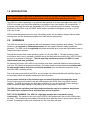
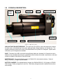
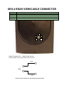
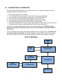
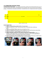
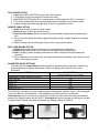
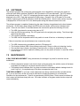
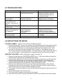
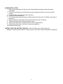
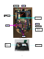
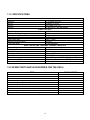
XRS-4 X-RAY SOURCE OPERATOR’S MANUAL CONTENTS ITEM PAGE 1.0 2.0 INTRODUCTION................................................................................. 2 WARNINGS......................................................................................... 2 DUTY CYCLE……………………………………………………………. 2 3.0 PHYSICAL DESCRIPTION................................................................. 3 HIGH VOLTAGE PULSER/TUBEHEAD....................................…….. 3 BASE.................................................................................................. 3 BATTERY PACK……........................................................................ 3 BATTERY CHARGER........................................................................ 3 CONTROL MODULE…………………………..................................... 4 CABLE CONNECTOR DIAGRAM………………………………………. 5 4.0 DESCRIPTION OF OPERATION........................................................ 6 BLOCK DIAGRAM………………………………………………………… 6 5.0 OPERATING INSTRUCTIONS............................................................ 7 OPERATING PRECAUTIONS.........................................................…. 7 EXCLUSION ZONE………………………………………………………. 7 PULSE SELECTION …………………………………………………….. 7 REMOTE CABLE OPTION……………………………………………… 8 DELAY MODE OPTION…………………………………………............ 8 REAL TIME IMAGING OPTION………………………………………… 8 PULSE SETTINGS............................................................................. 8 6.0 SOFTWARE........................................................................................ 9 7.0 MAINTENANCE.................................................................................. 9 DOSE MEASUREMENT…………………….…………………………. 9 TUBE REPLACEMENT………………………………………………... 9 8.0 TROUBLE-SHOOTING....................................................................... 10 9.0 INSTRUCTIONS FOR REPAIR......................................................... 10 FUSE REPLACEMENT………………………………………………. 10 REMOVING BOARDS………………………………………………… 10 BOARD INSTALLATION……………………………………………… 11 BATTERY DISPOSAL………………………………………………… 11 10.0 WARRANTY...................................................................................... 13 RETURNING REPAIR INSTRUCTIONS ……………………………. 13 11.0 SPECIFICATIONS............................................................................. 14 PHYSICAL DIMENSIONS................................................................ 14 X-RAY OUTPUT............................................................................... 14 ELECTRICAL & THERMAL CHARACTERISTICS…...................…. 14 12.0 SPARE PARTS………………………………………………………… 14 -1- 1.0 INTRODUCTION The XRS-4 produces high levels of radiation and must be operated by qualified personnel who have read the Warning and Operations section of the manual before operating the device. The XRS-4 is a small, lightweight x-ray generator that operates on its own removable battery pack. The XRS-4 is a pulsed x-ray device that produces x-ray pulses of very short duration (50 nanoseconds). It produces a relatively low dose rate comparable to a 0.25 ma constant potential machine. The energy produced by the XRS-4 is up to 370KVP, which makes it possible to radiograph up to one (1.5) inch (3.81 cm) of steel. XRS-4 standard accessories are two keys, two battery packs, and one battery charger. Remote cable, carrying case, and film developing equipment are also common accessories. 2.0 WARNINGS The XRS-4 is a pulsed X-ray generator that emits hazardous ionizing radiation when pulsing. The XRS-4 should only be operated by authorized personnel who are properly trained to safely operate the generator. The XRS-4 must be registered with proper authorities prior to use and should not be used to intentionally expose humans. Develop and closely follow a safe operating system for using the XRS-4. The safe operating system must ensure that no one is exposed to radiation above the permissible limits which are 2 mR (0.02 mSv) per hour for a member of the public. The safe operating system must ensure the XRS-4 is used within federal and state guidelines. All operators and users of the XRS-4 x-ray machine must wear a personal radiation monitoring device, such as a TLD (thermo luminescent dosimeter), film badge, and/or a pocket dosimeter consistent with the appropriate federal, territorial or provincial standards (note: an electronic dosimeter will not detect the XRS-4 radiation pulses). Due to the short pulse width of the XRS-4, survey meters of the Geiger-Mueller and scintillator type do not accurately detect the radiation emitted from the x-ray source. Survey meters should be of the ionization type and should be used in the integration mode. Survey meters must not be used in the rate mode because the XRS-4 does not produce constant radiation. The XRS-4 produces very high rates of radiation for very short periods of time resulting in either unrealistically high readings or no readings for a survey meter in rate mode. The XRS-4 has no explosion proof rating and should not be used in an explosive atmosphere. The Spark Gap is vented to the air and could be a source of ignition. DUTY CYCLE WARNING. The XRS-4 is a light duty machine that is not made to pulse continuously. The maximum duty cycle for the XRS-4 is 200 pulses every four minutes (3000 pulses per hour). Two consecutive pulse trains of 99 pulses can be fired then the unit should rest at least four minutes. Exceeding the duty cycle will shorten the life of the tube and head. 3.0 PHYSICAL DESCRIPTION BEAM ANGLE LABEL HANDLE HEAD KEY CONTROL MODULE BATTERY COLLIMATOR BASE RADIATION WARNING LABEL Figure 1: XRS-4 X-ray Unit HIGH VOLTAGE PULSER/TUBEHEAD. The main body of the XRS-4 is the tube head which contains the tube cavity, cold cathode type X-ray tube, spark gap, high voltage capacitor, and transformer. The standard collimator located on the front of the head limits the X-ray beam to 40 degrees. Special order collimators up to 85 degrees are available. BASE. The base of the XRS-4 contains the identification label and a threaded ¼-20 insert that can be attached to any standard camera tripod. Identification label indicates the model, manufacturer, and serial number is located on the bottom of the XRS-4 base. BATTERY PACK. The standard battery pack is a DeWalt 18V nickel-cadmium battery. Optional battery chemistry or voltage may be available. BATTERY CHARGER: The standard battery charger is the DeWalt DW9116 110V charger or DE9108 220V charger. Battery charge time is one hour. See battery charger manual for additional instructions and warnings. 3 3.5 CONTROL MODULE X-RAY PULSING LIGHT KEY LCD EMERGENCY STOP \ PULSE DEFAULT DELAY SWITCH UNITS SWITCH RANGE SWITCH POWER ON LIGHT BACK PLATE CABLE CONNECTOR Figure 3: Control Module POWER ON LIGHT: Illuminates when battery voltage is applied to control module. RED X-RAY PULSING LIGHT: Blinks after time delay button or remote cable button is pressed to warn that the XRS-4 is going to pulse. The light stays on continuously while the XRS-4 is pulsing. This is a failsafe warning light. If the light does not work the X-ray unit will not pulse. LIQUID CRYSTAL DISPLAY (LCD): Two digit LCD displays selected pulse, time before unit pulses, software version, and total number of pulses on the unit. RANGE SWITCH: Used to alternate LCD between tens digit and ones digit. UNITS SWITCH: Used to change the value of the tens digit or units digit from 0 to 9. The UNITS SWITCH is also used with the EMERGENCY STOP SWITCH to alter the default pulse setting. DELAY SWITCH: Initiates delay mode. EMERGENCY STOP SWITCH: Stops the unit before it begins pulsing or stops the unit in the middle of a pulse train. This switch can also be pressed with the UNITS SWITCH to alter the default pulse setting when the XRS-4 is first powered up. CABLE CONNECTOR: Lemo connector located on the back of the control module beneath the battery receives the remote cable or imaging system cable. See Rear View Diagram on page 5 for details. BACK PLATE: Covers the Oscillator board and contains battery terminal connectors. 4 XRS-4 REAR VIEW/CABLE CONNECTOR PIN # 1 2 3 4 5 DESCRIPTION +5 VOLTS 100 ma MAXIMUM REMOTE SWITCH REMOTE SWITCH – NO DELAY X-RAY ON SIGNAL COMMON 0 VOLTS 1 2 3 5 4 REMOTE CONNECTOR: LEMO EPG.0B.305.HLN MATING CABLE PLUG: LEMO FGG.0B.305.CLAD 56Z PIN 2 PIN 5 Remote switch inputs are activated when grounded. 5 4.0 DESCRIPTION OF OPERATION The block diagram below illustrates how the XRS-4 functions. The following sequence of events takes place each time the XRS-4 is fired: 1. 2. 3. 4. 5. 6. 7. User initiates operation of the machine. The control section sends a signal to the converter section to begin oscillating. Once oscillating, the converter section changes the 18 volts DC to 22Khz AC. The transformer charges the High Voltage Capacitor to about 9000 volts. The spark gap arcs after the High Voltage Capacitor reaches proper voltage. The pulse detector signals the control block that the unit has pulsed. As the High Voltage Switch is closed, a high voltage transient of approximately 270,000 volts and 50 nanoseconds in duration is applied across the x-ray tube generating x-rays. The closing of the High Voltage Switch produces an audible pulsing sound. The XRS-4 cannot produce x-rays without the pulsing sound so it serves as an additional warning the XRS-4 is functioning. This unit generates x-rays through high voltage bombardment of a tungsten target. The XRS-4 does not contain radioactive materials. All the high voltage is contained within the aluminum canister and as long as the canister is not punctured the operator is not exposed to dangerous voltages. BLOCK DIAGRAM X-RAY TUBE SPARK GAP HIGH VOLTAGE CAPACITOR PULSE DETECTOR CONVERTER USER INTERFACE CONTROLLER BATTERY 6 5.0 OPERATING INSTRUCTIONS OPERATING PRECAUTIONS: The operator should always stand at least 20 feet behind the X-ray unit and clear all personnel at least 20 feet behind the unit or at least 100 ft. from the front of the unit before pulsing. The exclusion zone (below) should be a controlled area free of all personnel while X-ray pulses. 20’ 100’ 20’ X-ray Beam 20’ Figure 4: Exclusion Zone PULSE SELECTION 1. Attach a charged battery and turn on the X-ray generator. 2. Press the RANGE BUTTON. The one’s digit of the LCD will blink twice and then go blank. 3. Press the UNITS BUTTON to adjust the ones digit from 0 to 9. 4. Press the RANGE BUTTON again and the tens digit of the LCD will blink twice and go blank. 5. Press the UNITS BUTTON to change the tens digit from 0 to 9. 6. Press the RANGE or UNITS BUTTON again to accept the new pulse setting. 7. Both tens digit and units digit will blink to indicate acceptance of the new pulse setting. (If RANGE or UNITS BUTTON is not selected after entering the pulse count the generator will automatically accept the entered pulse setting after six seconds). 8. Press the UNITS BUTTON and EMERGENCY STOP BUTTON simultaneously to lock in pulse setting. XRS-4 will retain locked in pulse setting until it is changed. Select ones digit Enter ones value(0-9) 7 Enter tens value (0-9) Change pulse default (optional) DELAY MODE OPTION 1. Press Green DELAY BUTTON on top of the control module. 2. LCD displays 60 and X-ray begins 60 second time delay. 3. Hold DELAY BUTTON down for 1.5 seconds and time delay goes from 60 to 15 seconds. 4. X-ray makes audible beep and red pulsing light blinks as generator counts down to pulse. 5. Audible warning and red warning light stay on while X-ray generator pulses. REMOTE CABLE OPTION 1. Attach remote cable to back of control module. 2. Retreat distance of the cable behind the unit. 3. Press and hold down button on the end of the remote cable until generator completes pulse train. 4. There is 5 second safety delay before generator begins pulsing. Audible beep and red pulsing light blink. 5. Audible warning and red pulsing light stay on while X-ray generator pulses. REAL TIME IMAGING OPTION 1. Change pulse setting default to 99 pulses if it is not already set to 99 pulses. 2. Attach imager cable to back of the control module unless using wireless option. 3. Refer to imaging system operating instructions for details on pulse setting and pulsing the generator. 4. There is no delay in this mode so the X-ray generator pulses immediately unless there is a time delay on the imaging system. SUGGESTED PULSE SETTINGS The chart below lists approximate pulses necessary to penetrate various materials. Settings vary greatly depending on imaging system used. Refer to imaging system instructions for more information. MATERIAL PULSE SETTING 24 inches between x-ray & imager CARDBOARD / LIGHT WOOD / PLASTIC 2 LIGHT METAL 5-10 STEEL 1/4” 25 STEEL 1” 50 STEEL 1.5” 99 BRASS 1/8” to ¼” 50- 99 The following is true when using film or digital systems that generate a positive image. If the radiograph is too dark, the film is underexposed. If the radiograph is too light the film is overexposed. Underexposure can be corrected by increasing the number of pulses and/or decreasing the distance between the imaging medium and the XRS-4. Overexposure can be corrected by reducing the number of pulses and/or increasing the distance between the imaging medium and XRS-4. Underexposed Overexposed 8 Correct exposure (pulse setting) 6.0 SOFTWARE The software program that controls the microcontroller can be identified by turning the key switch on while both push button switches (RANGE & UNITS) below the LCD are depressed. The LCD displays the software version “65”. After “65” is displayed the total number of pulses on the XRS-4 will be displayed in the LCD. Each digit represents 10,000 pulses. Example: If the LCD reads “04” the total number of pulses on the XRS-4 is between 40,000 and 50,000 pulses. After the total number of pulses is displayed the LCD will read “00” or the default pulse setting that was last stored on the unit. The software program is capable of determining the state of battery charge based on the time between each pulse. As the battery loses charge the XRS-4 pulse rate slows, with more time between each pulse. If there is more than 0.33 seconds between two consecutive pulses the following will occur: The XRS-4 continues the current pulse train to “00”. After the XRS-4 stops pulsing. The LCD goes back to the original pulse setting. The left and right digits blink alternately. The condition indicates a low battery. The XRS-4 will be inoperable until the key switch is turned off and on, or the battery is replaced. If there is more than one second between two consecutive pulses. 7.0 The XRS-4 stops pulsing immediately and the LCD displays 00. This function prevents XRS-4 from pulsing continuously if there is a failure in detecting circuitry. This condition may indicate a low battery, electrical noise, or failure in detecting circuitry. The operator may need to replace the battery pack, turn key switch off and on, or send the XRS-4 back for repair. MAINTENANCE X-RAY DOSE MEASUREMENT Using a dosimeter, the average X-ray dose for new tube can be established. With the dosimeter located 1 foot from the front of the case and in line with the center of the beam angle label, the reading for 10 pulses should be 26 mR to 36 mR. The leakage sheet illustrates the X-ray dose and maximum allowable radiation leakage levels for each X-ray unit. A completed copy of this form accompanies each X-ray. TUBE REPLACEMENT If you have a tube replacement kit refer to instructional disk included with the kit. If you do not have a kit the unit must be sent back to Golden Engineering or an Authorized Distributor for tube replacement. Tube life is approximately 50,000 pulses. Under normal conditions the tube’s output will decrease slowly with use. If the tube is broken or the glass cracks the tube output will cease immediately. 9 8.0 TROUBLESHOOTING SYMPTOM No “power on” light TEST -Check battery voltage -Check battery connection Power on lights, but X-ray does not pulse. Power on lights, X-ray pulsing light does not illuminate, X-ray dose not pulse X-ray pulses, but no image or black image. Unit stops pulsing in the middle of a pulse train and LCD displays 00. -Check the battery voltage. -Check the 2amp fuse. ACTION - Replace or charge battery - Make sure battery is securely attached and battery clips are not bent or broken. -Charge or replace the battery. -Replace the fuse if necessary. - Replace the X-ray pulsing light -Test X-ray output. -Replace the tube. -Check the battery voltage. -Check 15 amp fuse. -Check feedback line connection. - Charge battery if necessary. - Replace the fuse if blown. - Make sure the screw holding wire to the oscillator board is tight. - Stop immediately and return for repair. Return for repair. Unit makes loud popping noise while pulsing. Oil leaking from unit. 9.0 INSTRUCTIONS FOR REPAIR FUSE REPLACEMENT Requires T-10 Torx driver & needle nose pliers. 1. Remove the back plate. Remove the 5 screws in the back plate then pull the back plate off slowly maneuvering the battery terminal connecting wires through the opening in the oscillator board. 2. The 15 amp fuse is the white one inch long fuse on the left side of the oscillator board. The 2 amp fuse is a small green fuse just to the right of the 15 amp fuse. See diagram on page 12. The 15 amp fuse can be removed with fingers. The 2 amp fuse may require needle nose pliers to pull it out of the board. It should be pulled in a downward direction to remove from the board. REMOVING THE BOARDS Refer to the diagram on page 12 for steps 1-4. 1. Remove the back plate (see FUSE REPLACEMENT step 1). After the terminals are through the oscillator board, disconnect the red and black battery wires. 2. There are three terminals on the lower left side of the oscillator board and one on the lower right. Disconnect the two blue wires, one red wire, and one green signal wire using Philips driver. 3. There are three socket head cap screws holding the oscillator board in place. Two are in the middle of the board and one is at the bottom. Remove these three screws. 4. Disconnect the oscillator board from the counter board by pulling the bottom of the oscillator board up and away from the counter board. Disconnect the two pin white key switch connector, white three pin remote connector and black touch pad connector. 5. Tilt the back of the counter board down until the LED clears the housing then pull the board out of the housing. 6. Remove the top plate of the control module. 7. The counter board is located on the bottom of the top plate. 8. Disconnect the key switch connector and ribbon connector from the bottom of the counter board. 10 BOARD INSTALLATION 1. Slide counter board back into the top of the Control Module housing just below the screw receptacles. 2. Push the counter board up so LED goes through the appropriate hole in the control module housing. 3. Connect the three white and one black connector. 4. Screw the LED cover back on. 5. Put the three cap screws through the oscillator board and then put the ½” offsets on the back of the screws. 6. Plug the oscillator board back into the counter board and push it in position. 7. Tighten the three screws holding the board in place. 8. Insert the flat head screw in upper left corner of the oscillator board. 9. Attach the two blue wires, one red wire, and green signal line. 10. Reinstall the back plate. INSTRUCTIONS FOR BATTERY DISPOSAL Follow all federal, state, and local laws for disposal of nickel-cadmium batteries. Batteries may be returned to Golden Engineering for disposal. 11 2 AMP FUSE STEP 1 15 AMP 15 AMP FUSE FUS E POWER TRANSISTORS STEP 2 STEP 2 SIGNAL WIRE X-RAY ON / FEEDBACK SWITCH STEP 3 Figure 7:Oscillator Board KEY SWITCH CONNECTOR RIBBON CABLE Counter Board 12 10.0 WARRANTY Golden Engineering, Inc. warrants XRS-4 X-ray unit made and sold by it or its authorized representatives to be free of defects in materials and workmanship for a period of twelve (12) months from the date of shipment to the end user. Warranty does not cover maintenance required due to life. To make a claim under this limited warranty, customer must ship the entire unit (or the component believed to be defective) to Golden Engineering, post-paid. Golden Engineering, Inc. assumes no liability for units or components shipped until they are actually in the custody of Golden Engineering, Inc. Provided Golden Engineering, Inc. in its sole discretion, is satisfied that the failure is not the result of excessive use, abuse, misuse, accident, modification or improper disassembly or repair, Golden Engineering will provide parts and labor required to repair the unit. Golden Engineering reserves the right to use reconditioned and remanufactured components that meet original specifications. The unit or component will be return shipped to customer at customer's expense. THIS EXPRESS LIMITED WARRANTY IS IN LIEU OF ALL OTHER WARRANTIES AND GUARANTEES, EITHER EXPRESS OR IMPLIED OR CREATED BY OPERATION OF LAW. THE XRS-4 X-Ray Source is manufactured by: GOLDEN ENGINEERING, INC. PO BOX 185 CENTERVILLE, IN 47330 USA Phone: 1-765/855-3493 Fax: 1-765/855-3492 WEB: www.goldenengineering.com RETURNING UNIT FOR REPAIR Complete the repair form at www.goldenengineering.com/technical.html and include a copy of the printed form with the repair. If you do not have internet access prior to sending repair then include a letter containing a brief description of the problem, contact name, phone number, and return address. Remove battery before shipping the unit. Accessories are not necessary with units shipped back for repair. Be sure the unit is securely packaged for shipment and wrap in plastic bag if there is an oil leak. Ship to address: Golden Engineering 6364 Means Road, Centerville, IN 47330 USA Phone: 1-765-855-3493 EMAIL: [email protected] 13 11.0 SPECIFICATIONS PHYSICAL DIMENSIONS INCLUDING BATTERY PACK LENGTH WIDTH HEIGHT WEIGHT 17.5 inches (44.5 cm) 5 inches (13.5 cm) 8.5 inches (21.6 cm) 21 pounds (9.5 Kg) with battery X-RAY OUTPUT X-ray dose per pulse Pulses per battery charge Pulses per second Expected tube life (glass tube) X-ray source size Maximum Photon Energy X-ray pulse width 4 mR to 7 mR (12 inches in front of unit) 3000 10 (Nominal) 50,000 pulses 1/8 in. (3mm) 370 KVP 50 nanoseconds ELECTRICAL AND THERMAL CHARACTERISTICS Battery voltage Battery type Battery recharge time Current draw Current flow Temperature range Maximum duty cycle Warm-up 18 volts Nickel Cadmium sub C cells One Hour 13 amps @ 18 volts 0.25 mA -10 to 120 degrees F (-23 to 50 degrees C) 200 pulses every 4 minutes (3000 pulses per hour) None required 12.0 SPARE PARTS AND ACCESSORIES FOR THE XRS-4 ITEM PART NUMBER Thumbwheel Key Flat key DeWalt Battery DC 9091 DeWalt Battery Charger (110V) DW9116 DeWalt Battery Charger (220V) DE9108 Remote Cable Tripod Mount Handle – Left Side Handle – Right Side Carrying case (holds X-ray, 2 batteries, charger, cable) 14 5951070 5951040 4100030 4100040 4100055 1596110 2008010 2004021 2004020 4001655