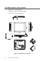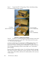
1
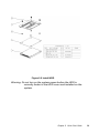
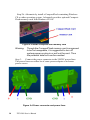
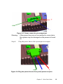
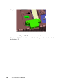
TPC-1260
High performance operator interface
terminal with 12.1” flat panel display
User's Manual
Copyright notice
This document is copyrighted 2001 by Advantech Co., Ltd. All rights
are reserved. Advantech Co., Ltd. reserves the right to make improvements to the products described in this manual at any time without
notice.
No part of this manual may be reproduced, copied, translated or
transmitted in any form or by any means without the prior written
permission of Advantech Co., Ltd. Information provided in this manual
is intended to be accurate and reliable. However, Advantech Co., Ltd.
assumes no responsibility for its use, nor for any infringements upon
the rights of third parties which may result from its use.
Acknowledgments
TPC-1260 is a trademark of Advantech Co., Ltd. IBM, PC/AT, and PS/2
are trademarks of International Business Machines Corporation. MSDOS and Windows CE are trademarks of Microsoft Corporation. All
other brand and product names mentioned herein are trademarks or
registered trademarks of their respective holders.
1st edition May 2001
Packing List
In the whole set of TPC-1260 there are items as listed below:
1.
TPC-1260T x 1 unit
2.
Accessory kit which includes:
(1)
HDD cover screws x 4 pieces
(2)
HDD cushions x 4 pieces
(3)
Panel mounting clamper x 8 pieces
(4)
Panel mounting screws x 8 pieces
(5)
PC/104 plus expansion board standoff x 4 pieces
(6)
3-pin power connector x 1 piece
(7)
TPC-1260 support CD x 1 piece
(8)
32MB CompactFlash memory card with Windows CE operating
system x 1 piece*1
(9)
1 meter 9-pin to 9-pin null modem cable x 1 piece*1
(10)
Microsoft Windows CE end user license agreement x 1 piece*1
Remark:
1. Only available in the model bundled with
Windows CE OS
FCC Class A
This equipment has been tested and found to comply with the limits
for a Class A digital device, pursuant to Part 15 of the FCC Rules.
These limits are designed to provide reasonable protection against
harmful interference when the equipment is operated in a commercial
environment. This equipment generates, uses and can radiate radio
frequency energy. If not installed and used in accordance with this
user's manual, it may cause harmful interference to radio communications. Operation of this equipment in a residential area is likely to
cause harmful interference, in which case the user will be required to
correct the interference at his own expense.
Safety Instructions
1.
Read these safety instructions carefully.
2.
Keep this installation reference guide for later reference.
3.
Disconnect this equipment from any AC outlet before cleaning. Do not use
liquid or spray detergents for cleaning. Use a damp cloth.
4.
For pluggable equipment, the power outlet must be installed near the
equipment and must be easily accessible.
5.
Keep this equipment away from humidity.
6.
Put this equipment on a reliable surface during installation. Dropping it or
letting it fall could cause damage.
7.
The openings on the enclosure are for air convection. Protect the equipment from overheating. DO NOT COVER THE OPENINGS.
8.
Make sure the voltage of the power source is correct before connecting the
equipment to the power outlet.
9.
Position the power cord so that people cannot step on it. Do not place
anything over the power cord.
10. All cautions and warnings on the equipment should be noted.
11. If the equipment is not used for a long time, disconnect it from the power
source to avoid damage by transient over-voltage.
12. Never pour any liquid into an opening. This could cause fire or electrical
shock.
13. Never open the equipment. For safety reasons, the equipment should be
opened only by qualified service personnel.
14. If any of the following situations arises, get the equipment checked by
service personnel:
a. The power cord or plug is damaged.
b. Liquid has penetrated into the equipment.
c. The equipment has been exposed to moisture.
d. The equipment does not work well, or you cannot get it to work
according to the installation reference guide.
e. The equipment has been dropped and damaged.
f. The equipment has obvious signs of breakage.
15. DO NOT LEAVE THIS EQUIPMENT IN AN UNCONTROLLED
ENVIRONMENT WHERE THE STORAGE TEMPERATURE IS BELOW 20° C (-4° F) OR ABOVE 60° C (140° F). IT MAY DAMAGE THE
EQUIPMENT.
The sound pressure level at the operator's position according to IEC 704-1:1982
is equal to or less than 70 dB(A).
Wichtige Sicherheishinweise
1.
Bitte lesen sie Sich diese Hinweise sorgfältig durch.
2.
Heben Sie diese Anleitung für den späteren Gebrauch auf.
3.
Vor jedem Reinigen ist das Gerät vom Stromnetz zu trennen. Verwenden Sie
Keine Flüssig-oder Aerosolreiniger. Am besten dient ein angefeuchtetes Tuch
zur Reinigung.
4.
Die NetzanschluBsteckdose soll nahe dem Gerät angebracht und leicht
zugänglich sein.
5.
Das Gerät ist vor Feuchtigkeit zu schützen.
6.
Bei der Aufstellung des Gerätes ist auf sicheren Stand zu achten. Ein Kippen
oder Fallen könnte Verletzungen hervorrufen.
7.
Die Belüftungsöffnungen dienen zur Luftzirkulation die das Gerät vor
überhitzung schützt. Sorgen Sie dafür, daB diese Öffnungen nicht abgedeckt
werden.
8.
Beachten Sie beim AnschluB an das Stromnetz die AnschluBwerte.
9.
Verlegen Sie die NetzanschluBleitung so, daB niemand darüber fallen kann. Es
sollte auch nichts auf der Leitung abgestellt werden.
10. Alle Hinweise und Warnungen die sich am Geräten befinden sind zu beachten.
11. Wird das Gerät über einen längeren Zeitraum nicht benutzt, sollten Sie es
vom Stromnetz trennen. Somit wird im Falle einer Überspannung eine
Beschädigung vermieden.
12. Durch die Lüftungsöffnungen dürfen niemals Gegenstände oder Flüssigkeiten
in das Gerät gelangen. Dies könnte einen Brand bzw. elektrischen Schlag
auslösen.
13. Öffnen Sie niemals das Gerät. Das Gerät darf aus Gründen der elektrischen
Sicherheit nur von authorisiertem Servicepersonal geöffnet werden.
14. Wenn folgende Situationen auftreten ist das Gerät vom Stromnetz zu trennen
und von einer qualifizierten Servicestelle zu überprüfen:
a. Netzkabel oder Netzstecker sind beschädigt.
b. Flüssigkeit ist in das Gerät eingedrungen.
c. Das Gerät war Feuchtigkeit ausgesetzt.
d. Wenn das Gerät nicht der Bedienungsanleitung entsprechend
funktioniert oder Sie mit Hilfe dieser Anleitung keine Verbesserung
erzielen.
e. Das Gerät ist gefallen und/oder das Gehäuse ist beschädigt.
f. Wenn das Gerät deutliche Anzeichen eines Defektes aufweist.
15. Bitte lassen Sie das Gerät nicht unbehehrt hinten unter -20° C (-4° F) oder
oben 60° C (140° F), weil diesen Temperaturen das Gerät zerstören könten.
Der arbeitsplatzbezogene Schalldruckpegel nach DIN 45 635 Teil 1000 beträgt
70dB(A) oder weiger.
DISCLAIMER: This set of instructions is provided according to IEC704-1.
Advantech disclaims all responsibility for the accuracy of any statements
contained therein.
Contents
Chapter 1 General Information .................................. 1
1.1 Introduction .................................................................. 2
1.2 Specifications ............................................................... 3
1.3 LCD specifications ...................................................... 5
1.4 Touchscreen specifications ........................................ 6
1.5 Power ............................................................................ 6
1.6 I/O ports arrangement................................................ 6
1.7 Mounting ...................................................................... 7
1.8 Exploded diagram ....................................................... 9
1.9 Dimensions and cutout ................................................. 10
Chapter 2 System Quick Starting ............................ 11
Chapter 3 The Engine of the TPC-1260 .................. 17
3.1 Introduction ................................................................ 18
3.2 CPC-2365 main board .............................................. 18
3.3 TPC-1260 I/O board ..................................................... 20
Chapter 4 Windows CE in the TPC-1260 ................ 25
4.1
4.2
4.3
4.4
Introduction ................................................................ 26
TPC-1260 utilities ..................................................... 27
Networking ................................................................. 30
Application program development ......................... 35
Chapter 5 System Tuning ........................................ 37
5.1
5.2
LCD contrast tuning ................................................. 38
Touchscreen calibration ........................................... 39
5.2.1 DOS ..................................................................... 39
5.2.2 Windows CE ......................................................... 39
Chapter 6 Maintenance ............................................ 45
6.1
6.2
CPU board replacement ........................................... 46
HDD replacement ..................................................... 48
Appendix A Serial Port Settings .............................. 49
A.1 Baud Rate Settings (SW1) .......................................... 50
A.2 Data Format/RS-422 Control Settings ...................... 51
Appendix B
Watchdog Timer Programming Example ................ 53
B.1
Watchdog timer programming example ................. 54
Appendix C
Windows 2000 Touch Screen Installation .............. 55
C.1
Touchscreen driver in Windows 2000 ................... 56
Appendix D Fuse Specifications ............................. 65
D.1
Fuse Specifications .................................................. 66
Figures
Figure
Figure
Figure
Figure
Figure
Figure
Figure
Figure
Figure
Figure
Figure
Figure
Figure
Figure
Figure
Figure
Figure
Figure
1.7-1 Panel mounting .................................................................... 7
1.6-1 I/O ports arrangement .......................................................... 7
1.8-1Exploded diagram ................................................................. 9
1.9-1 Dimensions and cutout ...................................................... 10
2-1 Unpack the package ............................................................. 12
2-2 Install HDD ............................................................................ 13
2-3 Install CompactFlash memory card ...................................... 13
2-4 Power connector and power lines ........................................ 14
2-5 Power connector pin assignment ........................................ 14
2-6 Plug the power lines to the system power receptor. ............. 15
2-7 Turn on power switch ............................................................ 15
3.2-1 TPC-1260 main board ........................................................ 18
4.1-1 Windows CE on TPC-1260 ................................................ 26
4.2-1 Soft-keyboard ...................................................................... 27
4.2-2 Screen saver setting ........................................................... 28
4.2-3 Regflash ............................................................................. 29
4.2-4 Regflash commands .......................................................... 30
4.3-1: Control Panel ..................................................................... 30
Figure
Figure
Figure
Figure
Figure
Figure
Figure
Figure
Figure
Figure
Figure
Figure
Figure
Figure
Figure
Figure
Figure
Figure
Figure
Figure
Figure
Figure
Figure
Figure
Figure
Figure
Figure
Figure
Figure
Figure
4.3-2: Neworking by Windows Explorer ....................................... 31
4.3-3 Remote networking ............................................................ 32
4.3-4 Make new connection ........................................................ 33
4.3-5 Direct connection ............................................................... 33
4.3-6 Default settings .................................................................. 34
4.3-7 Default settings (continued) .............................................. 34
4.4-1 Flow-chart of building Windows CE runtime ..................... 36
5.1-2 Remove the CPU Board cover ........................................... 38
5.1-1 Adjust LCD contrast ............................................................ 38
5.1-3 Adjusting the LCD brightness ............................................ 39
5.2-1 Start/Programs ................................................................... 39
5.2-2 Windows Explorer ............................................................... 40
5.2-3Control Panel ....................................................................... 40
5.2-4 Calibration .......................................................................... 41
5.2-5 Double-tap calibration ........................................................ 41
5.2-6 Stylus pointing calibration .................................................. 42
5.2-7 Calibration screen .............................................................. 43
6.1-1 CPU board cover ................................................................ 46
6.1-2 Remove the CPU board cover ............................................ 46
6.1-3 Remove the CPU board ..................................................... 47
6.2-1 Replace the fuse ................................................................ 48
C-1 Hardware ............................................................................... 56
C-2 Device manager .................................................................... 57
C-3 Uninstall the driver ................................................................ 58
C-4 Mouse properties ................................................................. 59
C-5 Update driver ........................................................................ 60
C-6 Select driver from known list ................................................ 61
C-7 Find out TouchScreen in the manufacturers list .................. 62
C-8 Re-install the driver .............................................................. 63
C-9 Finish installation of touchscreen driver .............................. 64
Tables
Table
Table
Table
Table
Table
1.3-1 LCD specifications ................................................................. 5
1.4-1 Touchscreen specifications ................................................... 6
3.2-1 TPC-1260 main board connector/jumper list ...................... 18
3.2-2 J1 RTC control jumper ......................................................... 19
3.3-1 TPC-1260 I/O board connector/jumper list .......................... 20
CHAPTER
1
General
Information
This chapter gives background
information on the TPC-1260.
Sections include:
• Introduction
• Specifications
• LCD Specifications
• Touchscreen specifications
• Power
• I/O ports
• Mounting
• Exploded diagram
• Dimensions and cutout
1.1 Introduction
The TPC-1260 touch panel computer is a revolutionary product of HMI
(Human Machine Interface). This 12.1” display operator interface is a
x86-based platform with these key features:
-- All in on platform: the CPU, DRAM or even Windows CE are
integrated. It is a plug-and-play machine compared with those socalled panel PCs.
- Slim but robust: the TPC-1260 is very thin (50mm thickness);
nevertheless its Mg-Al bezel provides amazing structural strength and
EMI reduction.
- Excellent display: the high brightness TFT LCD display fits the
industrial demand well.
- Fan-less and modular CPU board: the introduction of low power
processor prevents this system from unreliable fans. In addition, the
modular design facilitates the maintenance or possible upgrade on the
CPU board.
- Powerful communication capability: the TPC-1260 provides serial
ports, parallel port, Ethernet, USB and PC/104 plus expansion slot.
Almost all communications devices can access to this system.
- Windows CE support: in addition to DOS and Windows 9x series,
Advantech also offers platform support for Windows CE. The optional
Windows CE operating system specifically for the TPC-1260 is
available for Windows CE application program builders.
2
TPC-1260 User's Manual
1.2 Specifications
1.2.1 System kernel (CPC-2365)
- CPU: Transmeta CrusoeTM TM5400 (clock rate 500 MHz)
- BIOS: Award 256 KB flash memory
- South bridge: VIA 82C686A
- VGA: Silicon Motion SMI710/712 VGA/LCD controller; PCI 2.1
compliant; 4 MB embedded DRAM
- DRAM: built-in 128 MB SDRAM; among which 16 MB is occupied
by CPU (Code MorphingTM Software) and the other 112 MB is available for users
- Ethernet: NS DP83815 10/100Base-T Ethernet controller; IEEE 802.3u
protocol compatible
- Watchdog timer: MAX706 watchdog timer; 1.6 second timeout
period
- IDE: 1 EIDE channel supports one 2.5” IDE HDD and one CompactFlash card simultaneously
- Floppy diskette: the TPC-1260 does not provide floppy disk interface
1.2.2 I/O ports
- 1 parallel port: supports EPP/ECP modes
- 4 serial ports: RS-232 (COM1~COM3) and RS-422/485 (COM4)
- 1 RJ-45 Ethernet port
- 2 PS/2 ports: 6-pin mini-DIN ports for keyboard and mouse
- 1 USB: USB 1.0 compliant
- 1 PC/104 plus expansion slot: 32-bit PCI expansion slot in PC/104
plus form factor
Chapter 1 General Information
3
1.1.3 Storage
The TPC-1260 provides one EIDE channel for one 2.5” 44-pin HDD and
one CompactFlash card. The system boot-up sequence is:
- HDD and CompactFlash exist simultaneously: the system will boot
from the HDD. The HDD must be set as master. If the HDD does not
contain operating system, the TPC-1260 will automatically boot from
the CompactFlash.
- HDD exists only: the system will boot from the HDD
- CompactFlash card exists only: the system will boot from the
CompactFlash
1.1.4
Safety and environment
Safety
- FCC class A and CE certificated
- BSMI certificated
- The front bezel is compliant with NEMA 4
Environment
- Operating temperature: 0~50 degrees Celsius
- Storage temperature: -20~60 degrees Celsius
- Humidity: 10~95% @ 40°C relative humidity (non-condensing)
- Vibration: 10~18 Hz: 1.5mm peak-to-peak displacement; 18~500 Hz: 1G
acceleration
4
TPC-1260 User's Manual
1.3 LCD specifications
D is play Type
TFT color LCD
Size (D iagonal)
12.1"
M aximum R e s olution
800x600 (SVGA)
M aximum Colors
256K
Pixe l pitch (WxH, mm)
0.3075 x 0.3075
Vie wing angle
100
Luminance (cd/m )
110
Contras t ratio
250
2
Ope rating te mpe rature ( C)
0- 50 (ambient)
VR control
Brightness adjustable
Backlight
2 CCFL replaceable
LCD M TBF
140,000 hours
Backlight M TTF
50,000 hours
o
Table 1.3-1 LCD specifications
Notice:
There might be several bright or dark pixels on the
LCD. This comes from the production of the LCD.
Such phenomenon is claimed to be normal according
to the LCD manufacturers.
Chapter 1 General Information
5
1.4 Touchscreen specifications
Type
Resistive
Bas e glas s cons truction
Tempered Glass
Re s olution
Continuous
Light Trans mis s ion
75% typical
Controlle r
PS/2 interface
Powe r Rating
3.3 to 5 V
Software drive r
Windows CE (embedded)
Durability
100 million touches
DC
Table 1.4-1 Touchscreen specifications
1.5 Power
- Input voltage: 24VDC (the fuse will be open circuit as input level
exceeds 33VDC)
- Maximum current: 2 A
1.6 I/O ports arrangement
The TPC-1260 has 4 serial ports, 1 parallel port, 1 USB port, 2 PS/2
ports, 1 RJ-45 LAN port and a PC/104+ expansion slot. The arrangement of these ports is shown in Figure 1.6-1.
6
TPC-1260 User's Manual
Figure 1.6-1 I/O ports arrangement
1.7 Mounting
1.7.1
Panel mounting
1.There is a piece of adhesive waterproof gasket on the Mg-Al front
bezel. Make sure the waterproof gasket is in position before install the
TPC-1260 to the panel opening.
2.Install the TPC-1260 to the panel opening.
3.Find out the eight clampers and eight long screws in the accessory
pack. Hook those clampers to those holes around the four sides of the
bezel. Insert the screws to every clamper and fasten them. These
screws will then push on the mounting panel and fix the unit.
4.The mounting panel thickness is suggested to be less than 6mm
(0.236 inch).
<6mm
Figure 1.7-1 Panel mounting
Chapter 1 General Information
7
1.7.2
Wall mounting/desktop stand
There are two pairs of threaded holes on the sides of the front bezel.
They are used for wall mounting or desktop mounting. Please contact
with local Advantech sales representatives for these mounting kits.
8
TPC-1260 User's Manual
1.8 Exploded diagram
Figure 1.8-1Exploded diagram
Chapter 1 General Information
9
1.9 Dimensions and cutout
- Weight: 2.2 kg (without HDD)
- Dimension: 311 x 237 x 50 mm (WxHxD)
- Cutout: 302 x 228 mm (suggested)
Figure 1.9-1 Dimensions and cutout
10
TPC-1260 User's Manual
CHAPTER
2
System Quick Starting
This chapter provides a brief explanation for
operating the TPC-1260. With these step-by-step
guidelines it's easy to make the TPC-1260 start
working.
Step 1:
Unpack the TPC-1260 package. Please check the packing
list at the beginning of this manual.
Cushion
(P/N: 2130201590)
Accesory Box
(P/N: 2110002150)
Gift Box
(P/N: 2110002430)
Figure 2-1 Unpack the package
Step 2a: Install a 2.5" HDD containing certain operating system (and
even application programs) on the TPC-1260. Please refer to section
1.2.3 for the boot-up sequence.
As shown in the Figure 2-2, align the 2.5” HDD so that its four screw
holes are upward. Usually this would make the HDD PCBA side
upward too. Put the insulating sheet on the HDD. Carefully install the
four vibration-absorbing cushions on the HDD cover. Fasten these
parts together.
Now the HDD subassembly is done. It is self-aligned that the internal
IDE cable can only be connected in correct direction. Connect the IDE
cable to this subassembly and fasten the subassembly to the rear case
of the system.
12
TPC-1260 User's Manual
Figure 2-2 Install HDD
Warning: Do not turn on the system power before the HDD is
correctly fasten to the HDD cover and installed on the
system.
Chapter 2 Quick Start Guide
13
Step 2b: Alternatively install a CompactFlash containing Windows
CE or other operating system. Advantech provides optional CompactFlash memory cards with Windows CE OS.
Figure 2-3 Install CompactFlash memory card
Warning:
Though the CompactFlash memory card is supposed
to be hot swappable, it is suggested to turn off
system power as plug in or pull out the card. Thus
the potential data loss can be avoided.
Step 3:
Connect the power connector to the 24VDC power lines.
The power lines can either be of some power adapter or in-house
power source.
Figure 2-4 Power connector and power lines
14
TPC-1260 User's Manual
Figure 2-5 Power connector pin assignment
Warning:
Step 4:
If the power lines are not connected to correct pins,
the system may be damaged as the power is turned
on.
Plug the power lines to the system power receptor.
Figure 2-6 Plug the power lines to the system power receptor.
Chapter 2 Quick Start Guide
15
Step 5
Turn on the system power switch.
Figure 2-7 Turn on power switch
Step 6
Calibrate touchscreen. The detailed procedure is described
in section 5.2.
16
TPC-1260 User's Manual
CHAPTER
3
The Engine of the
TPC-1260
The operating engine of the TPC-1260
is composed of two PC boards:
the main boards and the I/O boards
3.1 Introduction
The engine of the TPC-1260 is constructed by the combination of two
PCBA—one main board and one I/O board. Such combination makes
system customization feasible.
3.2 CPC-2365 main board
Figure 3.2-1 TPC-1260 main board
Labe l
Function
CN2
Card PC connector (SODIMM 144 Pin)
CN3
Card PC connector (FPC 50 Pin)
CN5
Available for free use
J1
RTC control jumper (3 Pin)
J2
TDM connector (30 Pin)
Table 3.2-1 TPC-1260 main board connector/jumper list
18
TPC-1260 User's Manual
3.2.1 Connector pin assingments
1- 2 short
RTC battery on (default)
2- 3 short
Clear BIOS
Table 3.2-2 J1 RTC control jumper
Chapter 3 The Engine of the TPC-1260
19
3.3 TPC-1260 I/O board
Figure 3.3-1 TPC-1260 I/O board (I/O port side)
20
TPC-1260 User's Manual
Figure 3.3-2 TPC-1260 I/O board (LCD side)
Chapter 3 The Engine of the TPC-1260
21
Labe l
Function
CN1
Card PC connector (SODIMM 144Pin)
CN2
PC104 Plus connector (30x4 Pin)
CN3
Card PC connector (ZIF 50 Pin )
CN5
IDE connector (44Pin)
CN6
Parallel port connector (25 Pin)
CN7
PS2 mouse connector
CN8
PS2 keyboard connector
CN9
USB connector
CN10 LAN connector
CN11 RS422/RS485 connector
CN12 COM3 connector
CN13 COM2 connector
CN14 COM1 connector
CN15 Power connector
CN16 Touch screen connector
CN17 Flat panel display connector
CN19 Compact flash connector
CN20 Inverter power connector
SW1
RS422/RS485 setting switch
SW2
RS422/RS485 setting switch
SW4
System power connector
FS1
Fuse connector
VR1
Backlight brightness adjustment
Table 3.3-1 TPC-1260 I/O board connector/jumper list
22
TPC-1260 User's Manual
CHAPTER
4
Windows CE in
the TPC-1260
4.1 Introduction
The TPC-1260 operator interface terminal is designed to serve on the
Windows CE platform. The Windows CE is a compact operating
system that occupies less storage space or system resources compared with other operating systems. By its modular nature, it is
possible to choose those functions that are useful for specific application. Not only reducing the system resources required, it also reduces
start-up time. In the field of industrial automation or for operator
interface terminal, this is an appealing feature because the impact of
downtime would be minimized. Furthermore, the small storage space it
needs makes operating system on solid-state disk possible.
Figure 4.1-1 Windows CE on TPC-1260
26
TPC-1260 User's Manual
4.2 TPC-1260 utilities
There are several useful utilities built in the standard Windows CE OS
of TPC-1260:
4.2.1
Soft-keyboard
The TPC-1260 is dedicated to the small-sized operator interface. To
keep security of the whole automation system the TPC-1260 does not
provide PS/2 ports that connect to external keyboards or mice. On the
other hand, a software keyboard is embedded in the standard TPC1260 OS. Upon boot-up, a small keyboard icon would appear on the
status bar. Tap this icon by the stylus to activate/hide this Softkeyboard.
Figure 4.2-1 Soft-keyboard
4.2.2
Screen saver
From time to time it is unnecessary to turn on the TPC-1260 display all
the day. The TPC-1260 Windows CE OS provides a utility to turn off
theLCD and backlight, and thus elongates the display repair period.
When the system finishes boot-up a small icon “S” appears on the
status bar. Tap this icon by a stylus the setting window pops out.
Chapter 4 Windows CE in the TPC-1260
27
Figure 4.2-2 Screen saver setting
When the screen saver setting is done, tap “OK” to accept the
settings just made, “Cancel” to discard or “Save” to permanently save
the settings to the registry.
Notice:
4.2.3
Please be careful when selecting “Save”. This
command will overwrite all registry data—not only the
screen saving settings.
Watchdog timer
It is important in industrial applications that the control systems are
rarely down, or are capable of self-reset if they are halted somehow.
The watchdog timer is therefore used in the TPC-1260 to provide
automatic reset. There is a timer inside the watchdog timer. The TPC1260 should clear the timer within a pre-set time interval periodically. If
the timer is not cleared, the timer would assume the system to be
halted and generate a reset.
The watchdog timer in the TPC-1260 provides a fixed time interval: 1.6
seconds. As mentioned in the section 4.2.2: when the system boots,
there is an icon “S” on the status bar. Tap this icon by a stylus for the
setting window.
Select whichever time interval required, and tap one of the buttons:
“OK”, “Cancel” or “Save”.
Notice:
28
Please be careful before selecting “Save”. This
command will overwrite all registry data—not only the
watchdog timer settings.
TPC-1260 User's Manual
4.3 Networking
4.3.1
Networking via Ethernet
The TPC-1260 is equipped with a 100 Base-T Ethernet controller. To
utilize it, change the device name when the TPC-1260 is first turned on.
Step 1:
Click “Start/Settings/Control Panel”
Figure 4.3-1: Control Panel
Chapter 4 Windows CE in the TPC-1260
29
Step 2:
Double click “Communications”
Step 3:
Find the default device name. Change it to a unique one
depending on the plan of individual LANs.
Step 4:
Use the command “Regsave” to save this changed name
Step 5:
If the TPC-1260 is a node of a LAN with DHCP servers, it is
now available.
Step 6:
If the TPC-1260 is a node of a LAN with fixed IP server,
please consult with MIS to get specific IP address. Click
“Start/Settings/Control Panel”. Double click “Network” and
update the IP address.
Step 7:
Use the command “Regsave” or the utility “Regflash” to
save this changed name.
Figure 4.3-2: Neworking by Windows Explorer
30
TPC-1260 User's Manual
4.3.2
Networking via serial port
The TPC-1260 with built-in Windows CE supports serial connection to
host computers. The host computer must install the Microsoft
ActiveSync service offered by Microsoft. Use a null modem cable
bundled with the TPC-1260 to connect the serial ports of the host
computer and the TPC-1260. Then activate ActiveSync service on the
host computer. The host will automatically scan its serial ports and
make a connection.
Step 1:
Make sure the Microsoft ActiveSynce service and the
Microsoft embedded Visual Tools are properly installed in
the host PC.
Step 2:
Connect the two RS-232 ports of the host PC and the TPC1260 by a null modem cable.
Step 3:
If users are using the Microsoft eMbedded Visual Tools to
develop Windows CE application runtimes, make sure the
TPC-1260 SDK provided in the TPC-1260 support CD is also
properly installed in the host PC.
Step 4:
Click "Start/Programs/Communication/Remote Networking"
Figure 4.3-3 Remote networking
Chapter 4 Windows CE in the TPC-1260
31
Step 5:
Make a new connection. As the dialogue box pops out,
choose the default "Direct Connection".
Figure 4.3-4 Make new connection
Figure 4.3-5 Direct connection
32
TPC-1260 User's Manual
Step 6:
Click "Next" and "Finish" to complete making new connec
tion. It is recommended to keep the default settings of the
serial ports connection.
Figure 4.3-6 Default settings
Figure 4.3-7 Default settings (continued)
Chapter 4 Windows CE in the TPC-1260
33
Step 7:
If the ActiveSync service on the host PC has been activat
ed, the above six steps will make the TPC-1260 automatical
ly try to connect the host.
4.3.3
Web browser
The TPC-1260 built-in Windows CE OS includes Microsoft Pocket IE.
It can be used to browse web pages on World Wide Web via LAN or
dial-up connection.
4.4 Application program development
The TPC-1260 is bundled with built-in Windows CE operating system.
In real applications users need to execute various application programs
on it. However, unlike its other family the Windows CE is a hardwaredependent operating system. That is to say, Windows CE application
programs are only portable in the source code level. Users must
rebuild the runtime file for a different Windows CE platform even
though the source code may not be changed at all.
4.4.1
System requirements
- Intel Pentium-90 CPU or more advanced
- Microsoft Windows 2000 Professional or Windows NT Workstation
4.0
- Microsoft eMbedded Visual Tools 3.0
- Platform SDK for TPC-1260 (bundled in the standard TPC-1260T-CE)
- 64MB DRAM
- CD-ROM drive
- Monitor with VGA resolution at least
- Mouse
- 200MB free hard disk space at least
- Connection to the same LAN as the TPC-1260 if LAN is used for
development TPC-1260
- TPC-1260T-CE
34
TPC-1260 User's Manual
- Connection to the same LAN as the host PC if LAN is used for
development
- Null modem cable (bundled in the standard TPC-1260T-CE)
4.4.2
Building Windows CE runtime
By the platform SDK bundled with the standard TPC-1260, users can
build the Windows CE runtime by the eMbedded Visual Tools.
Figure 4.4-1 Flow-chart of building Windows CE runtime
Chapter 4 Windows CE in the TPC-1260
35
36
TPC-1260 User's Manual
CHAPTER
System Tuning
5
5.1 LCD contrast tuning
5.1
LCD brightness tuning
The display brightness of the TPC-1260 is designed to be adjustable.
Remove the screw on the CPU board cover. Then slide the CPU board
cover toward the PC/104+ slot. Take away the CPU board cover.
Figure 5.1-1 Adjust LCD contrast
Figure 5.1-2 Remove the CPU Board cover
There is a variant resistor near the upper edge of the opening. Use a
blade screwdriver to adjust the LCD brightness so that it looks good in
certain surrounding lighting.
38
TPC-1260 User's Manual
Figure 5.1-3 Adjusting the LCD brightness
5.2
Touchscreen calibration
5.2.1 DOS/Windows Family
Please find out the DOS and Windows 95/98 touchscreen drivers in the
support CD
The TPC-1260 touchscreen drivers support DOS/Windows 9x/
Windows NT/Windows 2000/Windows Me.
5.2.2 Windows CE
Step 1: From the Windows CE status bar, click “Start/Programs”
Chapter 5 System Tune Up
39
Step 2: Double-click “Windows Explorer”
Figure 5.2-2 Windows Explorer
Step 3: Double-click “Control Panel”
Figure 5.2-3Control Panel
40
TPC-1260 User's Manual
Step 4:
In the Control Panel window find the "Stylus" icon
and double-click it.
Step 5:
The calibration window will appear with two tabs—Double
Tap and Calibration.
Figure 5.2-4 Calibration
Step 6:
The Double Tap page is to record the user’s individual time
period between the two tapping when he double-taps in
Windows CE.
Figure 5.2-5 Double-tap calibration
Step 7:
The Calibration page is to calibrate touchscreen-to-display
locations correspondence. This ensure the Windows CE
right reaction to user’s click or double-click events.
Chapter 5 System Tune Up
41
Figure 5.2-6 Stylus pointing calibration
Step 8:
Click the “Recalibrate” button. A cross will appear on the
screen by the order of center point, upper-left, lower-left,
lower right and upper-right corners. Use the stylus to press
the center of the cross until the cross moves to next
location.
Figure 5.2-7 Calibration screen
Step 9: When calibration is done the utility will save the settings.
42
TPC-1260 User's Manual
Chapter 5 System Tune Up
43
44
TPC-1260 User's Manual
CHAPTER
Maintenance
6
The TPC-1260 is designed to be modular, slim and lightweight for
easier maintenance. The following sections are dedicated to describe
how a qualified technician can replace major components.
6.1
CPU board replacement
Step 1: Remove the screw on the CPU board cover.
Step 2: Slide the CPU board cover toward the opposite side of the I/O
ports.
Figure 6.1-1 CPU board cover
Step 3: Take away the CPU board cover.
Figure 6.1-2 Remove the CPU board cover
46
TPC-642 User's Manual
Step 4: The CPU board is now visible. It connects to the I/O board by a
144-pin SO-DIMM connector and a 50-pin FPC connector.
Step 5: Use a pair of tweezers to loosen the 50-pin FPC connector, and
release the FPC.
Step 6: Bend outward the two metal latches of the SO-DIMM connec
tor by thumbs. The free end of the CPU board would swing up.
Pull out the CPU board.
Figure 6.1-3 Remove the CPU board
Step 7: Insert a new CPU board to the SO-DIMM connector.
Step 8: Push down and lock the CPU board.
Step 9: Use a pair of tweezers to insert the 50-pin FPC to the connector
on the CPU board. Then tighten the connector.
Step 10: Replace the CPU board cover and fasten the screw.
Warning:
The CPU cover is used as the cooling media of the
CPU. Thus it is usually of higher temperature than
other parts of the system. Be careful not to touch
this area without proper protection.
Chapter 1 General Information
47
6.2
Fuse replacement
Step 1: Remove the fuse cover.
Step 2: Replace the damaged fuse with a new one.
Step 3: Replace the fuse cover.
Figure 6.2-1 Replace the fuse
Warning:
48
1. Do not replace the fuse unless it is damaged.
2. Do not replace the fuse with a different rating.
TPC-642 User's Manual
APPENDIX
A
Serial Port Settings
Serial Port Settings
The COM4 serial port on the TPC-1260 is of RS-422 or RS-485. This
port is designed with auto data flow control capability. That is to say,
when the two wired RS-485 communication is activated, the TPC-1260
can automatically detect the data flow direction at this port. Its setting
are directed to two DIP switches SW1 and SW2. These two switches
are located near the lower edge of the opening when the CPU board
cover is removed.
A.1 Baud Rate Settings (SW1)
= On
50
TPC-642 User's Manual
= Off
*= Default
A.2 Data Format/RS-422 Control Settings
= On
= Off
*= Default
Appendix A Watchdog Timer
51
52
TPC-642 User's Manual
APPENDIX
B
Watchdog Timer
Programming
Example
B.1 Watchdog timer programming example
The watchdog timer built in the TPC-1260 is a useful aid to reduce
system down time-especially for those operating systems not reliable
enough. There is a counter inside the watchdog timer. If the system
does not constantly clear the counter within the timeout period, the
watchdog timer would initialize a system reset.
The following example program in assembly language gives hint to
utilize the watchdog timer under operating systems such as DOS,
Windows 9x/NT, etc.
Step 1: activate the watchdog timer
mov
dx, 404Ch
in
al, dx
and
al, NOT 80h
out
dx, al
; GPO7 to low
Step 2: clear the watchdog timer
mov
dx, 404Ch
in
al, dx
or
al, 80h
; GPO7 to high
out
dx, al
Step 3: re-trigger the watchdog timer
If the timer will not count the GP07 is kept high. To re-trigger the watchdog timer:
mov
dx, 404Ch
in
al, dx
and
al, NOT 80h
out
dx, al
Notice:
54
; GPO7 to low
the utility to enable/disable the watchdog timer under
Windows CE is built in the Advantech Windows CE
for TPC-1260.
TPC-1260 User's Manual
APPENDIX
C
Windows 2000
Touch Screen
Installation
C.1 Touchscreen driver in Windows 2000
Under the Windows 2000 operating system, the touchscreen driver is
somewhat sophisticated. After installing the touchscreen driver, the
system would restart automatically. And the following fine tuning is
required:
Step 1:
Find out the touchscreen driver that is on the TPC-1260
support CD. Execute the setup program. It will request a system reset
as the setup procedure is completed.
Step 2:
Click "Start/Settings/Control Panel"; double-click "System"
and go to the "Hardware" page.
Figure C-1 Hardware
56
TPC-1260 User's Manual
Step 3:
Click the "Device Manager…" button.
Figure C-2 Device manager
Appendix C Windows 2000
57
Step 4:
In the sub-category of "Mice and other pointing devices"
there is a exclamation mark appearing at the beginning of the line of
touchscreen. Move the cursor to this line "TouchScreen - PS/2 Mouse
[R411.PS2] and press right button of the mouse. Choose "Uninstall".
Figure C-3 Uninstall the driver
58
TPC-1260 User's Manual
Step 5:
Then move the cursor to the "Microsoft PS/2 mouse" or
"Other PS/2 compatible mouse), press the right button of the mouse.
Select "Properties"
Figure C-4 Mouse properties
Appendix C Windows 2000
59
Step 6:
button.
Go to the "Driver" page, and click the "Update Driver"
Figure C-5 Update driver
60
TPC-1260 User's Manual
Step 7:
Click "Next" button. Choose the "Display a list of the
known drivers for this device…" radial button. Click "Next" button.
Figure C-6 Select driver from known list
Appendix C Windows 2000
61
Step 8
In the "Manufacturers" list, find out and select "TouchScreen".
Figure C-7 Find out TouchScreen in the manufacturers list
62
TPC-1260 User's Manual
Step 9
Click the "Next" button to install driver. Ignore the warning
message appears.
Figure C-8 Re-install the driver
Appendix C Windows 2000
63
Step 10: When the installation finishes the system would restart.
Thus complete the setup of the touchscreen under Windows 2000.
Figure C-9 Finish installation of touchscreen driver
64
TPC-1260 User's Manual
APPENDIX
D
Fuse Specifications
D. Fuse Specifications
The fuse used on the TPC-1260 is:
Rating: 250VAC, 5Amp.
Size: 5 x 20mm
Notice:
66
The fuse is set to break as the input voltage exceeds
33 VDC for your protection.
TPC-1260 User's Manual