1
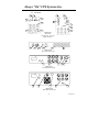
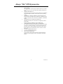
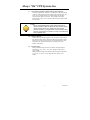
Always “On” UPS Systems Inc.
GES V-Series – Single Phase Input, Single Phase
Output
Uninterruptible Power Supply
GES-801V, GES-102V, GES-102VR, GES-152V, GES-152VR,
GES-222V, GES-222VR
Line Interactive (PWM): 800VA, 1kVA, 1.5kVA, 2.2kVA
User Manual
Version 2.2
Always “On” UPS Systems Inc.
SAVE THESE INSTRUCTIONS
This manual contains important instructions for the GES-801V, GES-102V, GES-102VR,
GES-152V, GES-152VR, GES-222V, GES-222VR and should be followed during
installation and maintenance of the UPS and batteries.
The UPS contains voltages that are potentially hazardous. Please contact our dealers or
qualified personnel for service.
Servicing of the batteries should be performed or supervised by personnel knowledgeable
with batteries and the required precautions. Keep unauthorized personnel away from
batteries.
When replacing batteries, replace with the same model number, type and rating.
CAUTION: Do not dispose of battery or batteries in a fire. The batteries may explode.
CAUTION: Do not open or mutilate the battery or batteries. Released electrolyte is
harmful to the skin and eyes. It may be toxic.
CAUTION: A battery can present a risk of electrical shock and high short circuit current.
The following precautions should be observed when working on or with the batteries.
−
Remove watches, rings, or other metal objects.
−
Use tools with insulated handles.
−
Wear rubber gloves and boots.
−
Do not lay tools or metal parts on top of batteries.
−
Disconnect charging source prior to connecting or disconnecting battery terminals.
−
Determine if the battery is inadvertently grounded. If inadvertently grounded,
remove source of ground. Contact with any part of a grounded battery can result in
electric shock. The likelihood of a shock will be reduced if grounds are removed
during installation and maintenance (applicable to a UPS and a remote battery
supply not having a grounded supply circuit).
CAUTION: To ensure the safety and performance of the UPS, never load the UPS with a
hair dryer, heater, laser printer or other types of inductive loads.
Always “On” UPS Systems Inc.
SAFETY INSTRUCTIONS
1.
The UPS has its own internal energy source (battery), therefore the output receptacles may
have electricity present even though the UPS is disconnected from the utility power.
2.
The DC voltage provided from the internal battery is 24Vdc for 801V, 102V,
152V, 102VR, 152VR. 48Vdc for 222V, 222VR.
3.
The isolated ground wire (green or green with yellow stripe) must meet national
wire requirements.
4.
The power plug to connect with the UPS has to be equipped with a ground plug.
5.
Battery must be replaced or serviced by qualified, knowledgeable, personnel.
6.
Replacement battery must be the type, quantity and configured the same as the
original(s).
7.
To avoid explosions, keep open flame and other heat emitting sources away from
battery.
8.
Do not disassemble or damage the battery. The electrolyte is toxic and especially
harmful to the eyes and skin.
9.
The battery contains high voltages and currents that are dangerous. To maintain
secure operation and performance of the UPS, the user must exercise basic and
regular maintenance.
10. Please follow the precautions below when dealing with the UPS:
1.
Do not remove the UPS cover unless authorized by factory. Removing the
cover will void the warranty.
2.
The UPS can only be connected to a 2-pole/3-wire plug.
3.
Do not install the UPS in an environment with excessive humidity.
4.
Do not allow liquids or foreign objects to get inside the UPS.
5.
Allow for air circulation through the UPS. A minimum clearance of 10cm is
required on all sides.
6.
Do not load the UPS with appliances such as a hair dryer, heater, vacuum,
kettle, etc.
7.
Keep the UPS away from direct sunlight and heat-emitting sources.
8.
Install the UPS as close as possible to the load for maximum protection.
11. Storage Requirements
1.
Recharge the UPS batteries every 6 months for no less than 8 hours at a time.
2.
Under a high ambient temperature environment, recharge the UPS batteries
every 3 months for no less than 8 hours at a time
12. High Voltage Risk:
1.
High voltages might exist between the battery terminal and the grounding
system, if the battery circuit has not been disconnected from the UPS circuit.
Please check this voltage before connecting.
2.
Disconnect the battery wires before proceeding with maintenance. High
voltages may be present between the UPS internal components and battery
even after the input power is disconnected.
Always “On” UPS Systems Inc.
Table of Contents
1.
INTRODUCTION
1
2.2.
PRESENTATION
Front Panel
Rear Panel
2
2
4
3.1.
3.2.
3.3.
3.4.
3.5.
3.6.
3.7.
3.8.
3.9.
INSTALLATION
Unpacking and Inspection
Placement
Connect Computer Interface (Optional)
Connect to Utility
Charging the Battery
Connecting the Loads
Connecting the Telephone / Modem / Ethernet Lines (Optional)
Storage Conditions
Extended Storage
6
6
6
6
6
6
6
7
7
7
4.1.
4.2.
4.3.
4.4.
4.5.
4.6.
4.7.
OPERATION
Switching “On” the UPS
Switching “Off” the UPS
Self-Test
Silence the Alarm
Cold Start
Shutdown Mode
Green Function
8
8
8
8
8
8
9
9
5.1.
5.2.
5.3.
5.4.
AUDIBLE ALARM
Back-Up (Slow Alarm)
Low Battery (Rapid Alarm)
Overload (Continuous Alarm)
Replace Battery (Continuous Alarm)
10
10
10
10
10
6.1.
6.2.
6.3.
6.4.
6.5.
SOFTWARE OPTIONS
UPSMON Software
Interface Kits
Computer Interface Port
Open Collector (Dry Contact) Communication
RS-232 Communication
10
10
10
11
11
11
2.
2.1.
3.
4.
5.
6.
7.
BATTERY REPLACEMENT
13
8.
TROUBLESHOOTING
General Problems
14
14
8.1.
9.
TOWER SPECIFICATIONS
15
10.
RACK MOUNT SPECIFICATIONS
16
CONTACT INFORMATION
Additional Purchases or Upgrades
QA / Warranty Questions
Software Questions
19
19
19
19
11.
11.1.
11.2.
11.3.
Always “On” UPS Systems Inc.
1.
INTRODUCTION
The V-Series is a Line Interactive UPS system that includes the newest and latest
technology enhancements. The Line Interactive technology with AVR function (online voltage boost-up & buck-down) allows for a wide input voltage range of 90 to
150VAC. The V-Series UPS is ideal protection for microprocessor control loads.
After the UPS has been turned “On” it will protect the load from transients, spikes
and other power aberrations. In the event of a blackout (or severe brownout) the UPS
will automatically switch to back-up mode and maintain power to the load until the
software shuts down the system or when the battery reaches a low voltage state. Also
included with our UPS systems is a cyclic self-testing function to verify both the
operation of the UPS and the condition of the battery.
In addition, the V-Series UPS provides advanced telephone line and Ethernet
surge suppression through the modular connectors on the back panel.
The Line Interactive UPS in conjunction with our monitoring software makes
your UPS operate intelligently and provides you with total protection for all
your loads.
Interference to Radio / TV
If this UPS causes interference to radio or television reception, which can be
determined by turning the UPS off and on, the user can attempt to correct the
interference by one or more of following measures:
1.
2.
3.
Connect the equipment to an outlet on a circuit different from the one that
the receiver is connected.
Increase the separation between the equipment and the receiver.
Re-orientate the receiving antenna.
1
Version 2.2
Always “On” UPS Systems Inc.
2.
PRESENTATION
2.1.
Front Panel
I
1
2
3
4
5
6
Figure 2.1.1
Tower Front Panel.
Always "
"On
7
8
9
1
5
6
10
Figure 2.1.2
102VR Front Panel
I
Line Mode
Boost
INV Mode
Buck
Battery Fault
Always "On"
6
5
1
2
3
4
Figure 2.1.3
152/222VR Front Panel.
2
Version 2.2
Always “On” UPS Systems Inc.
1
2
3
4
5
6
7
8
9
10
REPLACE BATTERY indicator (RED LED)
This LED illuminates when the UPS's batteries are no longer useful
and must be replaced.
Note: When replacing the batteries, disconnect the utility power and
then open the case. Take notice of the polarity before installing the
new batteries to avoid a short.
BUCK AVR (VOLTAGE REDUCTION) indicator (YELLOW LED)
This LED illuminates when the UPS is correcting a high utility
voltage condition. The loads receive normal power.
BACK-UP indicator (YELLOW LED)
This LED illuminates when the UPS is supplying battery power to the
loads.
BOOST AVR (VOLTAGE BOOST) indicator (YELLOW LED)
This LED illuminates when the UPS is correcting a low utility voltage
condition. The loads receive normal power.
LINE NORMAL indicator (GREEN LED)
This LED illuminates when the line-input voltage is normal. (RM
version; also flashes to indicate Backup mode)
ON/OFF/TEST/SILENCE button (TEST / SILENCE for GES102VR). Press and hold the button for more than 3 seconds to turn
the UPS “ON” or “OFF” (not applicable to GES-102VR). Press and
hold the button less than 1 second to activate a self-test, or silence the
back up alarm.
UPS OUTPUT SEGMENT 1 ON / OFF SWITCH
This switch allows independent ON / OFF control of UPS output
segment 1 outlets on rear panel.
UPS OUTPUT SEGMENT 2 ON / OFF SWITCH
This switch allows independent ON / OFF control of UPS output
segment 2 outlets on rear panel.
BYPASS ON/OFF SWITCH
This switch allows independent ON / OFF control of the surgeprotected outlet on rear panel. (This outlet is not supplied backup
power in the event of a power outage)
MAIN POWER
This toggle switch is the main power cutoff for the UPS. Use of this
switch will remove power from loads and completely shutdown the
UPS.
3
Version 2.2
Always “On” UPS Systems Inc.
2.2.
2
Rear Panel
3
1
2
4
1
3
5
6
8
7
8
7
Figure 2.2.1
Rear Panel
Left GES-801, 102, 152V
Right GES-222V
2
3
8
7
5
6
Figure 2.2.2
Rear Panel GES-102VR
INPUT
BREAKER
IN
OUT
REMOTE
PORT
OUTPUT
3
6
8
7
2
Figure 2.2.3
Rear Panel GES-152VR
OUTPUT
INPUT
BREAKER
REMOTE
3
8
7
6
2
Figure 2.2.2
Rear Panel GES-222VR
4
Version 2.2
Always “On” UPS Systems Inc.
1
2
3
4
5
6
7
8
MAIN POWER
This toggle switch is the main power cutoff for the UPS. Use of this
switch will remove power from loads and completely shutdown the
UPS.
COMPUTER INTERFACE
Both RS-232 and relay signal (Dry Contact) Interfaces are supplied to
support WINDOWS, NOVELL, UNIX, DOS, and other operating
systems.
TELEPHONE / MODEM / ETHERNET SURGE PROTECTION
Surge protection for telephone line, modem line, and 10BaseT line to
maintain a completely safe connection for INTERNET / INTRANET
service.
SITE WIRING FAULT INDICATOR (RED LED)
Illuminates when the UPS is connected to an improperly wired AC
power outlet.
Note: This device is available on 110 VAC models only.
SURGE PROTECTION OUTLET ONLY <NO BACKUP>
This full time surge protection outlet provides protection from surges
such as those created by lightning or connected equipment that has
high initial current. Plug in equipment that does not require power
during a blackout, this could include a printer, scanner, fax, audio
device, etc.
OUTPUT POWER RECEPTACLES
AC INPUT POWER RECEPTACLE
INPUT CIRCUIT BREAKER
Trips when the connected loads exceed the protected receptacle's
capacity. The center plungers of the circuit breakers extend when
tripped.
5
Version 2.2
Always “On” UPS Systems Inc.
3.
INSTALLATION
3.1.
Unpacking and Inspection
Examine the packaging for damage. Inform the carrier immediately if
damage is noticed. Retain the packaging for future use.
3.2.
Placement
Install the UPS in a protected area with adequate airflow and free of
excessive dust. Do not operate the UPS where the temperature and
humidity is outside the specified limits.
3.3.
Connect Computer Interface (Optional)
UPSMON (or other power management software) and an interface kit can
be used with this UPS. Use only kits supplied or approved by the
manufacturer. If used, connect the interface cable to the 9-pin computer
interface port on the back panel of the UPS (See Back Panel). This is
optional; UPS will work properly without a computer interface
connection.
3.4.
Connect to Utility
Connect the AC input power connector (Included) to utility power.
3.5.
Charging the Battery
The UPS charges its battery whenever the UPS is in LINE mode. For
best results, charge the battery for 4 hours initially before connecting the
load.
3.6.
Connecting the Loads
Plug the loads into the output connectors on the rear of the UPS. To use
the UPS as a master on/off switch, make sure all of the loads plugged into
the UPS are switched on.
Caution:
Never connect a laser printer or plotter to the UPS with other computer
equipment. A laser printer or plotter draws significantly more power on
start-up than when idle, and will overload the UPS. If a laser printer
or plotter requires protection against blackouts, brownouts and overvoltage the UPS needs to be increased in size to accommodate the
inrush of power.
6
Version 2.2
Always “On” UPS Systems Inc.
3.7.
Connecting the Telephone / Modem / Ethernet Lines (Optional)
Connect a telephone line, modem line, or 10BaseT line into the telephone
/ modem / ethernet surge protection sockets on the back of the UPS. The
RJ-45 / RJ-11 modular sockets accept standard single line telephone
connections and 10BaseT connectors. This connection will require
another length of cable. This is optional; UPS will work properly without
this connection.
Caution:
The line current limiting feature could be rendered inoperable if
improperly installed. Make sure that the line from the wall is plugged
into the connector marked “IN”, and the device to be protected
(telephone, modem, etc.) is plugged into the connector marked “OUT”.
This surge protection device is for indoor use only; never install wiring
during a lightning storm.
3.8.
Storage Conditions
Store the UPS covered and upright in a cool, dry location, with its battery
fully charged. Before storing, charge the UPS for at least eight (8) hours.
Remove any accessories in the accessory slot and disconnect any cables
connected to the computer interface port to avoid the unnecessary
draining of the battery.
3.9.
Extended Storage
During extended storage periods in environments where the ambient
temperature is -15 to +30°C (+5 to +86°F), charge the UPS‘s battery
every 6 months.
During extended storage in environments where the ambient temperature
is +30 to +45°C (+86 to +113°F), charge the UPS‘s battery every 3
months.
7
Version 2.2
Always “On” UPS Systems Inc.
4.
OPERATION
4.1.
Switching “On” the UPS
For all but the GES-102VR:
With the UPS plugged in and utility power present, press and hold the On
/ Off / Test / Silence Button more than 3 seconds or until the LED is lit.
The UPS will perform self-testing each time it is switched “On”.
For the GES-102VR:
With the UPS plugged in and utility power present, turn the Main Power
toggle switch to the “On” position. The UPS will perform self-testing
each time it is switched “On”.
4.2.
Switching “Off” the UPS
For all but the GES-102VR:
Press and hold the On / Off / Test / Silence Button for more than 3
seconds, or until the Line Normal or Back-Up LED turns off.
For the GES-102VR:
Turn the Main Power toggle switch to the “Off” position.
4.3.
Self-Test
Use the self-test to verify both the operation of the UPS and the condition
of the battery. When normal utility power is present, push the On / Off /
Test / Silence (Test / Silence for GES-102VR) Button for less than 1
second. During the self-test, the UPS operates in back-up mode.
During the self-test, the UPS briefly operates the loads with battery
power (the LED flashes every 2 seconds). If the UPS passes the selftest, it returns to on-line operation. The LED stops flashing and the
LED remains on. If the UPS fails the self-test it immediately returns
to on-line operation. The loads are unaffected when performing a
self-test. Recharge the battery overnight and perform the self-test
again. If the UPS still fails a self-test, ask our nearest dealer to
replace the battery.
4.4.
Silence the Alarm
In Back Up mode, push On / Off / Test / Silence (Test / Silence for GES102VR) Button for less than 1 second to silence the audible alarm. (This
function will not work when the UPS is in "LOW BATTERY" or
"OVERLOAD" condition.)
4.5.
Cold Start
When the UPS is off and there is no utility power, use the cold start
feature to apply power to the loads from the UPS's battery. Press the ON
/ TEST button (see Front Panel section for location of the indicator) until
the UPS beeps.
8
Version 2.2
Always “On” UPS Systems Inc.
4.6.
Shutdown Mode
In shutdown mode the UPS stops supplying power to the load and waits
for the return of utility power. If there is no utility power present, external
devices (e.g., servers) connected to the computer interface can command
the UPS to shutdown. This is normally done to preserve battery capacity
after the graceful shutdown of protected servers.
4.7.
Green Function
In order to conserve battery power when in backup mode the UPS will
automatically shutdown after 5 minutes if the connected loads are
operating at less than 20 watts.
To disable “GREEN FUNCTION” press and hold the “On” button during
initial start-up for at least 3 seconds until a beep-beep sound is heard.
9
Version 2.2
Always “On” UPS Systems Inc.
5.
6.
AUDIBLE ALARM
5.1.
Back-Up (Slow Alarm)
When in back-up mode, the LED flashes every 2 seconds and the UPS
sounds an audible alarm. The alarm stops when the UPS returns to line
normal operation. Press the On / Off / Test / Silence Button during backup mode to silence the beeping.
5.2.
Low Battery (Rapid Alarm)
In back-up mode, when the battery energy runs low, the UPS beeps
rapidly until the UPS shuts down from battery exhaustion or returns to line
normal operation.
5.3.
Overload (Continuous Alarm)
When the UPS is overloaded (the connected load exceeds the maximum
rated capacity of the UPS) the UPS sounds a continuous alarm to warn of
an overload condition. Disconnect non-essential loads until the UPS stops
the alarm.
5.4.
Replace Battery (Continuous Alarm)
The UPS emits a continuous beep if the battery fails the self-test. See
replace battery section for battery replacement or call your dealer for
service.
SOFTWARE OPTIONS
6.1.
UPSMON Software
The UPSMON software uses the standard RS-232 interface to perform
monitoring functions and then provides an orderly shutdown of a
computer in the event of power failure. Moreover, UPSMON displays all
diagnostics through a graphical display, such as Voltage, Frequency,
Battery Level, etc.
The software is available for DOS, Windows 3.1x, Windows 95 / 98 / 00 /
XP & Windows NT V3.5 or later.
6.2.
Interface Kits
A series of interface kits are available for various operating systems that
provide UPS monitoring. Each interface kit includes the special interface
cable required to convert status signals from the UPS into signals that the
individual operating system will recognize. The interface cable at the UPS
side must be connected to the REMOTE PORT, at the computer side it can
be connected to either COM1 or COM2. For other installation instructions
and powerful features please refer to READ ME file included within the
software.
Caution:
Use only factory supplied or authorized UPS monitoring kits!
10
Version 2.2
Always “On” UPS Systems Inc.
6.3.
Computer Interface Port
The communication port on the back of the UPS may be connected to a
host computer. This port allows the computer to monitor the status of the
UPS and control the operation of the UPS. Its major functions include the
following:
1.
The ability to broadcast a warning when the power fails.
2.
The ability to close any open files before the battery reserves are
exhausted.
3.
The ability to turn off the UPS.
4.
The ability to make the UPS perform a self-test.
Some computers are equipped with a serial connector to link with the
communication port, in some cases a special plug-in card may be needed.
6.4.
Open Collector (Dry Contact) Communication
[Pins for the GES-801V, GES-102V and GES-152V]
(Pins for the GES-222V)
1.
Pin [8] (5) and [6] (2) are open collector outputs that must be
pulled up to a common referenced supply no greater than
+40VDC.
2.
The transistors are capable of a maximum non-inductive load of
25mADC, use pin [5] (4) as the common.
3.
Pin [8] (5) generates a High to Low signal when the battery inside
the UPS has less than 5 minutes back up time left.
4.
Pin [6] (2) generates a High to Low signal when the line has
failed.
Pin [3] (7) will shut down the UPS is a high is sustained for 0.36
seconds.
6.5.
RS-232 Communication
[Pins for the GES-801V, GES-102V and GES-152V]
(Pins for the GES-222V)
5.
6.
7.
8.
9.
Pin [3] (7) is the RS-232 data input from computer (RX).
Pin [2] (6) is the RS-232 data output to computer (TX).
Pin [4] (8) is the RS-232 data transmit bit (DTR).
Pin [7] (9) is the RS-232 data receive bit (RTS).
Pin [5] (4) is the common or computer ground.
NOTE:
1. Switch rating +40V, 25mADC non-inductive.
2. Pin 7 should be connected to computer ground only.
11
Version 2.2
Always “On” UPS Systems Inc.
DB-9 Pin Configuration for the GES-801V, 102V, and 152V
1
6
8
6
5
Contacts
Normally
Open
2
7
3
8
Signal High Minimum 1 Second
4
9
5
3
2
7
4
1
Low Battery
Mains Failure
Common
UPS Shut Down or
RS-232 RD (PIN 3)
RS-232 TX (PIN 2)
RS-232 RTS (PIN 7)
RS-232 DTR (PIN 4)
DB-9 Pin Configuration for the Purple Cable (GES-222V)
1
6
5
2
4
Contacts
Normally
Open
2
7
3
8
Signal High Minimum 1 Second
4
9
5
12
7
6
9
8
3
Low Battery
Mains Failure
Common
UPS Shut Down or
RS-232 RD (PIN 3)
RS-232 TX (PIN 2)
RS-232 RTS (PIN 7)
RS-232 DTR (PIN 4)
Version 2.2
Always “On” UPS Systems Inc.
7.
BATTERY REPLACEMENT
WARNING:
Completing the procedure below will void any remaining warranty on
the UPS system.
Caution:
Do not dispose of battery in a fire. Do not attempt to open the battery.
When replacing the battery use tools with insulated handles and
remove watches, rings, etc…
Your battery should run anywhere from 3-5 years before it needs to be replaced.
Please follow the instructions below for easy, trouble free, battery replacement.
1.
Turn the UPS off (follow procedure previously mentioned).
2.
Unplug the UPS from utility power source and disconnect all connected loads.
3.
Disconnect AC power cord from unit.
4.
For the 801V / 102V / 152V / 222V: Pull on the top of the faceplate until the 2
top tabs release. Remove the faceplate and set to the side.
For the 152 / 222VR: Using a Phillips screwdriver, remove the 2 screws
holding the faceplate on. Remove the faceplate and set to the side.
For the 102VR: Turn the UPS upside down. Using a Phillips screwdriver
remove the 4 screws holding the top to the bottom. Flip the UPS right side
up. Remove the 8 screws for the handles and the one screw on the back.
5.
For the 801V / 102V / 152V / 222V: The battery retainer plate should be
visible. Using a Phillips screwdriver remove the screw at the battery plate
and set the plate to the side.
For the 152 / 222VR: The battery retainer plate should be visible. Using a
Phillips screwdriver remove the 3 screws holding the battery retainer plate
on and set the plate to the side.
For the 102VR: From the back pull the top cover off of the UPS.
6.
For the 801V / 102V / 152V / 222V: Carefully pull the batteries out of the UPS.
Remove the connecting wires noting polarity.
For the 152 / 222VR: Carefully pull the batteries out of the UPS using the
white tab hanging in front of the batteries. Remove the connecting wires
noting polarity.
For the 102VR: Remove the connecting wires from the batteries noting
polarity.
7.
You can now easily remove the battery from the unit
8.
Place your new battery in the same position, direction and reconnect the wires.
The red wire to the positive (+) pole and black wire to the negative (-) pole.
9.
Reverse the above steps to reassemble the unit.
10. Follow start-up instructions in order to properly reconnect your equipment.
13
Version 2.2
Always “On” UPS Systems Inc.
8.
TROUBLESHOOTING
Please follow the guidelines below for common problems:
Check UPS input plug and wiring.
Check UPS input voltage.
Please prepare the information as follows for service personnel:
UPS model number and serial number
Description of problem(s) in detail.
8.1.
General Problems
Problems
UPS has no reaction while
AC power is connected
UPS has no reaction while
AC power is connected, yet
starts after pushing power
on/off switch
Possible causes
Breaker at back panel open
No AC input
UPS fault
Battery failure
Solution
Replace Fuse / Switch breaker on
Check AC power
Call for service
Call service center to replace batteries
Breaker at back panel open
No AC input
UPS AC detecting circuit fail
Switch breaker
Check AC power
Call for service
Utility voltage or frequency
UPS goes into back-up mode
abnormal
while connected to AC power
UPS AC detecting circuit failure
Battery can not provide
Battery deteriorated
normal back-up power in the Batteries not fully charged
event of a blackout
Battery charger damaged
After AC connected to UPS,
Abnormal utility power
alarm sounds short and fast
beeps and UPS shuts down
14
Check AC power
Call for service
Charge batteries and reset
If that doesn’t work call for service
Check input power
Version 2.2
Always “On” UPS Systems Inc.
9.
TOWER SPECIFICATIONS
MODEL
GES-801V
Capacity
INPUT
800VA
Voltage
1kVA
1.5kVA
2.2kVA
Simulated sine wave at Line Input +/-5%
Frequency (on battery)
50 or 60Hz +/-0.5%
OUTPUT
±13% of nominal (120V)
Voltage Regulation AVR
Transfer Time
2/4 milliseconds, including detection time
Spike Protection
320 joules, 2ms
UPS automatic shutdown if overload exceeds 110% of nominal for
60 second or 130% for 3 seconds.
Unit Input
Fuse for overload & short circuit protection
10BaseT/Modem Line
Short Circuit
GES-222V
50 or 60Hz +/-5% (auto sensing)
Voltage (on battery)
Overload Protection
GES-152V
120V, 220V +/-25%
Frequency
PROTECTION and
FILTERING
GES-102V
Network (UTP, RJ-45) compatible jacks
UPS output cut off immediately or input fuse protection
Type
Maintenance-free, Sealed Lead Acid
Typical Recharge Time
4 hours (to 90% of full capacity)
BATTERY
Protection
Automatic self-test & discharge, replace battery indicator
Back-up Time
Net Weight kg(lbs)
Shipping Weight kg(lbs)
PHYSICAL
10 - 30 minutes (depending on load)
13 (28.6)
15 (33.0)
15.6 (34.3)
14.2 (31.2)
16.2 (35.6)
16.8 (36.9)
169x448x227
(6.6x17.6x8.9)
IEC 320 power inlet
Battery Back-Up
Slow beeping sound (about 0.47Hz)
Battery Low
Rapid beeping sound (about 1.824Hz)
Overload
INTERFACE
28.2 (62.0)
130x382x201
(5.1x15x7.9)
Dimension mm (inches)
WxDxH
Input Inlet
ALARM
26.2 (57.6)
Continuous beeping sound
RS-232/Dry Contact
YES
Safety
cUL UL1778, CSA C22.2 and FCC Class B
CONFORMANCE
Surge
Ambient Operation
ENVIRONMENT
IEEE C62.41 CAT. A
6,000 meters max. elevation, 0-95% humidity non-condensing 030°C
Audible noise
<40dBA (1 meter from surface)
Storage Condition
15000 meters max. Elevation
Specifications subject to change without prior notice to reflect upgrades and
improvements in technology.
15
Version 2.2
Always “On” UPS Systems Inc.
10. RACK MOUNT SPECIFICATIONS
V-SERIES
GENERAL
INPUT
MODEL NO.
MAXIMUM CAPACITY
GES-801V
GES-102V
GES-152V
GES-222V
800VA / 495W
1kVA / 600W
1.5kVA / 900W
2.2kVA/1320W
UPC ORDER CODE
825433 20500 825433 20600 825433 20700 825433 20850
NOMINAL VOLTAGE
120VAC (optional 220VAC)
VOLTAGE RANGE
+ / - 25%
FREQUENCY RANGE
50 or 60 Hz (+ / - 5%)
NOMINAL VOLTAGE
120VAC
VOLTAGE REGULATION
CURRENT
+ / - 13% of nominal
6.87A
FREQUENCY
OUTPUT
8.33A
12.5A
118.33A
50 / 60Hz (Auto Detected)
WAVEFORM
(ON BATTERY)
POWER FACTOR
PWM (Pulse Width Modulated) or Modified Sine Wave
< 0.6
CREST FACTOR
3:1 (on battery)
TRANSFER TIME
2 - 4 ms (Typical)
OUTLETS
4+1 Surge
16
4+1 Surge
4+1 Surge
Version 2.2
6
Always “On” UPS Systems Inc.
BATTERY TYPE
BATTERY
SEALED LEAD ACID - MAINTENANCE FREE
QUANTITY
2
VOLTAGE
2
2
24VDC
RECHARGE TIME
4 HOURS;
FULL LOAD
BACKUP
HALF LOAD
POWER TIME
PENTIUM & 17" MON
OUTPUT SHORT
4
48VDC
RECOVERY = 90%, TYPICALLY
≥ 10 MIN.
≥ 10 MIN.
≥ 10 MIN.
≥ 10 MIN.
≥ 25 MIN.
≥ 25 MIN.
≥ 25 MIN.
≥ 25 MIN.
≥ 35 MIN.
≥ 35 MIN.
≥ 45 MIN.
≥ 70 MIN.
YES
ABNORMAL VOLTAGE
PROTECTION MODEM OR NETWORK
I/O NOISE PROTECTION
I/O SPIKE & TRANSIENT
PROTECTION
COMMUNICATION
YES
SINGLE LINE (2 wire RJ-11) / NETWORK (UTP, RJ-45)
COMPATIBLE JACKS
COMMON & NORMAL MODE NOISE SUPPRESSION
YES
RS-232 / DRY CONTACT
Normal / Back-up / Low Battery / Fault / Check Battery /
Buck / Boost
INTERFACE LED DISPLAY
AUDIBLE ALARMS
On Battery, Low Battery, Overload, Fault
17
Version 2.2
Always “On” UPS Systems Inc.
OPERATING
TEMPERATURE
0 - 40°C (32 - 104°F)
ENVIRONMENT HUMIDITY
0% ~ 90% (Non-Condensing)
< 40 dBA AT 1 METER FROM UNIT
AUDIBLE NOISE
SAFETY
APPROVAL
SAFETY
cUL,
EMI / RFI
FCC CLASS B
SURGE / TRANSIENT
PHYSICAL DATA
UL1778, CSA C22.2
WxDxH mm (in.)
IEEE C62.41 CAT.A
170x450x214
(6.8x18x8.6)
130x382x201 (5.2x15.3x8)
WEIGHT in kg (lbs)
13 (28.7)
MODEL NO.
15 (33.1)
15.6 (34.4)
26.2 (57.8)
GES-102VR
GES-152VR
GES-222VR
825433 20603 825433 20701 825433 20851
UPC Order Code
Available
483x351x44
483x351x89 483x351x133
Consult
Manufacturer (19x13.8x1.75) (19x13.8x3.5) (19x13.8x5.25)
RACK-MOUNT
MODELS WxDxH mm (in.)
WEIGHT in kg (lbs)
18
[1U]
[2U]
[3U]
17.8 (39.2)
18.3 (40.3)
30.4 (67.0)
Version 2.2
Always “On” UPS Systems Inc.
11. CONTACT INFORMATION
11.1. Additional Purchases or Upgrades
Always “On” UPS Systems Inc.
Bldg 1 – 150 Campion Road,
Kelowna, BC, Canada, V1X 7S8
Phone: (250) 491-9777 Ext 451
Fax:
(250) 491-9775
Email: [email protected]
Website: www.alwaysonups.com
11.2. QA / Warranty Questions
Always “On” UPS Systems Inc.
Bldg 1 – 150 Campion Road,
Kelowna, BC, Canada, V1X 7S8
Phone: (250) 491-9777 Ext 209
Fax:
(250) 491-9775
Email: [email protected]
Website: www.alwaysonups.com
11.3. Software Questions
Always “On” UPS Systems Inc.
Bldg 1 – 150 Campion Road,
Kelowna, BC, Canada, V1X 7S8
Phone: (250) 491-9777 Ext 204
Fax:
(250) 491-9775
Email: [email protected]
Website: www.alwaysonups.com
19
Version 2.2