1
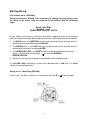
Installation Manual
Room Air Conditioners
R410A Split Type – Nouveau Series
DC INVERTER
ECO930SDN
ECO1230SDN
• Please read this installation manual completely before installing the
product.
• When the power cord is damaged, replacement work shall be performed by
authorized personnel only.
• Installation work must be performed in accordance with the national
wiring standards by authorized personnel only.
• Contact the authorised service technician for repair or maintenance of
this unit.
Register your air conditioner
Model information can be found on the CE
label.
Please register your product online at
www.ecoair.org. For your future
convenience, record the model information
below.
____________________________________
MODEL NUMBER
____________________________________
SERIAL NUMBER
____________________________________
PURCHASE DATE
1
Congratulations!
You have purchased the very latest in room air conditioner technology. Your new
EcoAir high efficiency room air conditioner will give you many years of dependable
service. Many features have been built into your EcoAir air conditioner to assure quiet
operation, the best circulation of cool, dry air, functional controls, and the most
economical operation.
2
Table of contents
DISPOSAL …………………………………………………………………………………….
5
BS PLUG WIRING ……………………………………………………………………….….
6
SAFETY PRECAUTIONS…………………………………………………………….…….
7
INSTALLATION OF INDOOR & OUTDOOR UNITS…………………………………….
8
ITEMS PACKED WITH THE UNITS ……………..……………………………………….
9
INSTALLATION INSTRUCTIONS………………………………………………………….
10
ELECTRICAL WORK………………………………………………………………….…….
16
AIR PURGING…………………………………………………………………………….….
18
IMPORTANT INFORMATION REGARDING REFRIGERANT USED ………………….
19
TEST RUNNING……………………………………………………………………….…….
20
SERVICE & WARRANTY…………….……………………………………………….…….
21
3
WARNING
•
•
•
Do not install, remove and reinstall the unit by yourself.
Improper installation will cause water leakage, electrical shock, or fire.
Please consult authorized dealer or specialist for the installation work.
Please note fault caused by improper installation is not covered by
warranty.
Unit must be installed in an easily accessible area. Any additional cost
required to hire special equipment to service the unit will be the
responsibility of the customer.
4
Disposal
When using this air conditioner in the European countries, the follow
information must be followed:
DISPOSAL: Do not dispose this product as unsorted waste.
It is prohibited to dispose of this appliance in domestic household waste.
For disposal:
A) Contact your local council for disposal.
B) The manufacturer will take back the old appliance for disposal when you replace
with a new product.
C) Old products contain valuable resources, which should be recycled as scrap
metal.
Wild disposal of waste in forests and landscapes endangers your health when
hazardous substances leak into the ground-water and find their way into the food
chain.
5
BS Plug Wiring
(For models up to 12000 Btu)
Wiring Instructions: Should it be necessary to change the plug please note
the wires in the mains lead are coloured in accordance with the following
code:
BLUE - NEUTRAL
BROWN – LIVE
GREEN AND YELLOW - EARTH
As the colours of the wires in the mains lead of this appliance may not correspond
with the coloured markings identifying the terminals in your plug, proceed as follows:
1. The BLUE wire is the NEUTRAL and must be connected to the terminal which is
marked with the letter N or coloured BLACK.
2. The BROWN wire is the LIVE and must be connected to the terminal which is
marked with the letter L or coloured RED.
3. The GREEN/YELLOW is the EARTH and must be connected to the terminal
which is marked with the letter E or
or coloured GREEN or
GREEN/YELLOW.
4. Always ensure that the cord grip is positioned and fastened correctly.
If a 13A (BS 1363) fused plug is used it must be fitted with a 13A fuse. If in doubt
consult a qualified electrician.
Wiring for a 13 Amp Plug (BS1363)
Please note. The Earth Terminal is marked with the letter E or
6
Earth Symbol.
Safety Precautions
The following should be always observed for safety:
•
•
•
Be sure to read the following WARNING before installing the air conditioner.
Be sure to observe the cautions specified here as they include important
items related to safety.
After reading this instruction, be sure to keep it together with the owner’s
manual in a handy place for future reference.
! WARNING
Perform the installation securely referring
to the installation instruction.
Installation only by Competent person.
●Incorrect
installation could cause injury due to fire,
electric shock, the unit falling or leakage of water.
Consult the dealer from whom you purchased the
unit or special installer
●
Perform electrical work according to the
installation manual and be sure to use
an exclusive circuit.
Install the unit securely in a place which
can bear the weight of the unit.
●
Incorrect installation could cause a personnel
injury due to fire, electric shock, the unit falling
or leakage of water.
When installed in an insufficiently strong place,
the unit could fall causing injury.
●
If the capacity of the power circuit is insufficient
or there is incomplete electrical work, it could
result in a fire or an electric shock.
Use the specified wires to connect the
indoor and outdoor units securely and
attach the wires firmly to the terminal
board connecting sections so the stress
of the wires is not applied to the sections
●Incorrect
Check that the refrigerant gas does
not leak after installation is completed.
connection and fixing could cause a fire.
Attach the electrical part cover to the indoor unit
Be sure to use the part provided or
specified parts for the installation work.
and the service panel to the outdoor unit securely.
●If
the electrical part covers of the indoor unit
and/or the service panel of the outdoor unit are
not attached securely, it could result in a fire or
electrical shock due to dust, water, etc.
●The
use of defective parts could cause an injury
due to a fire, electric shock, the unit falling, etc.
! CAUTIONS
Perform the drainage/piping work
Do not install the unit in a place
where a flammable gas leaks.
●
according to the installation instruction.
●If
there is a defect in the drainage/piping work,
water could leak from the unit and household
goods could get wet and be damaged.
If gas leaks and accumulates in the
area surrounding the unit, it could cause
an explosion.
7
Installation Of Indoor And Outdoor Units
Read completely, then follow step by step.
Indoor unit
• Do not expose the indoor unit to heat or steam.
• Select a place where there are no obstacles in
front or around the unit.
• Make sure that condensation drainage can
be conveniently routed away.
• Do not install near a doorway.
Fig. 1
• Ensure that the space on the left and right
of the unit is more than 12cm.
• Use a stud finder to locate studs to prevent unnecessary damage to the wall.
• A minimum pipe run of 3 metres is required to minimise vibration & excessive
noise. The indoor unit should be installed on the wall at a height of 2 metres or
more from the floor.
• The indoor unit should be installed allowing a minimum clearance of 15cm from
the ceiling.
• Any variations in pipe length will/may require adjustment to refrigerant charge.
• There should not be any direct sunlight. Otherwise, the sun will fade the plastic
cabinet and affect its appearance. If unavoidable, sunlight prevention should be
taken into consideration.
Outdoor unit
• If an awning is built over the outdoor unit to
prevent direct sunlight or rain exposure,
make sure that heat radiation from the
condenser is not restricted.
• Ensure that the clearance around the back
of the unit is more than 30cm and left side is
more than 30cm. The front of the unit should
have more than 200cm of clearance and the
connection side (right side) should have more
than 60cm of clearance.
• Do not place animals and plants in the path of the air inlet or outlet.
• Consider the weight of air conditioner when selecting the location because of its
noise and vibration.
• Select a proper place so that the warm air and noise from the air conditioner do
not disturb neighbours.
Rooftop installation:
• If the outdoor unit is installed on a roof structure, be sure to level the unit.
• Ensure the roof structure and anchoring method is adequate for the unit location.
• Consult local codes regarding rooftop mounting.
• If the outdoor unit is installed on roof structures or external walls, this may result
in excessive noise and vibration, and may also be classed as a non serviceable
installation.
8
Items Packed With The Unit
Number
1
2
3
4
5
6
7
8
9
Name of Accessories
Installation Plate
Clip Anchor
Self-tapping Screw A ST3.9X25
Seal (some models without)
Drain Joint
Liquid
side
Connecting pipe
assembly
Gas Side
Qty
1
8
8
1
1
6.35
9.53
9.53
12.7
Parts you must purchase. Check
pipe sizes for each of the Liquid
side and Gas side with your
dealer or specification of models
you purchased.
16.0
(A minimum pipe wall-thickness of
0.7mm is required)
Remote controller
Self-tapping Screw B ST2.9X10
Remote controller holder
1
2
1
Note: Except the above parts provided, the other parts needed during installation you must purchase
CAUTION
Ensure that the space around the left and right
of the indoor unit is more than 12cm. The
indoor unit should be installed allowing a
minimum clearance of 15cm from the ceiling.
Use a stud finder to locate studs to prevent
unnecessary damage to the wall.
A minimum pipe run of 3 metres is required to
minimise vibration & excessive noise. The
indoor unit should be installed on the wall at a
height of 2 metres or more from the floor.
Additional drain pipe
Two of the A, B and C directions should be
free from obstructions.
Wrapping tape
7
SET TEM PER ATURE(
C
)
AUTO
HEALTH
COOL
DRY
HIGH
MED
HEAT
LOW
A
MO
DE
SWING
CLEAR
AIR
AUTO
CLEAN
Loop the
connective
B
cable.
C
•
•
9
ADJUST
This illustration is for explanation purposes only.
Copper lines must be insulated independently.
9
ON/OFF FANSPEED
SLEEP
TIMERON
RE SE T L OCK
TIMEROFF
FOLLO
W
ME
LE
D
DISPLAY
TURB
O
8
Indoor Unit Installation
1. Fit the Installation Plate
1. Fit the installation plate horizontally on structural
parts of the wall with spaces around the
installation plate.
2. If the wall is made of brick, concrete or the like, drill
eight (8) 5mm diameter holes in the wall. Insert
Plastic Expansion Sheath for appropriate mounting
screws.
3. Fit the installation plate on the wall with eight (8)
type “A” screws
Note:
Fit the Installation Plate and drill holes in the wall according to the wall structure
and corresponding mounting points on the installation plate. (Dimensions are in
“mm” unless otherwise stated)
A:795, B:270(<12000Btu/h model); A:845, B:286(≥12000Btu/h model)
* Dimensions may vary.
2. Drill a hole in the wall
1. Determine hole positions according to the diagram as shown above. Drill
one (1) hole
( 65mm) slanting slightly to outdoor side.
2. Always use wall hole conduit when drilling metal grid, metal plate or the like.
10
3. Connective Pipe and Drainage Installation
Drainage
1.
Run the drain hose sloping downward. Do not install the drain hose as
illustrated below.
2.
When connecting extension drain hose, insulate the connecting part of
extension drain hose with a shield pipe, do not let the drain hose slack.
Connective pipe
1.
2.
3.
For the left-hand and right-hand piping, remove the pipe cover from the side
panel. Explain to clients that the pipe cover must be kept as it may be used
when relocate the air conditioner to any other place.
For the rear-right-hand and rear-left-hand piping, install the piping as shown.
Bend the connective pipe to be laid at 43mm height or less from the wall.
Fix the end of the connective pipe. (Refer to Tightening Connection in
REFRIGERANT PIPING CONNECTION)
4. Indoor unit installation
1.
2.
3.
4.
Pass the piping through the hole in the wall.
Put the upper claw at the back of the indoor unit on
the upper hook of the installation plate, move the indoor
unit from side to side to see that it is securely hooked.
For ease of fitting, insert a cushioning material between
the indoor unit and the wall.
Remove cushioning material after fitting.
Push the lower part of the indoor unit up on the wall,
Then move the indoor unit from side to side, up and down
to check if it is hooked securely.
11
5. Piping and wrapping
Bundle the tubing, connecting cable, and drain hose
with tape securely, evenly as shown in Fig.10.
Because the condensed water from rear of the indoor
unit is gathered in ponding box and is piped out of room.
Do not put anything else in the box
CAUTION
• Connect the indoor unit first, then the outdoor unit.
• Do not allow the piping to let out from the back of the indoor unit. Be careful
not to let the drain hose slack as slack may cause water drippage.
• Both Copper pipes must be properly lagged/insulated.
• Be sure that the drain hose is located at the lowest side of the bundle.
Locating at the upper side can cause water to overflow inside the unit.
• Never inter-cross nor inter-twist the power wire with any other wiring.
• Run the drain hose on a downward sloping angle to ensure water runs at
gravity pull straight to the water outlet outside.
Outdoor Unit Installation
Precaution
• To prevent exposure to the wind, install the outdoor unit with its suction side
facing the wall. Never install the outdoor unit at a site where the suction side
maybe exposed directly to the wind. To prevent exposure to the wind, it is
recommended to install a baffle plate on the air discharge side of the
outdoor unit.
•
In heavy snowfall areas, select an installation site
where the snow will not affect the unit. It is also
suggested to do the following:
o Construct a large canopy.
o Construct a pedestal.
o Install the unit high enough off the ground to
prevent burying in snow. Or use a bracket
•
Install the outdoor unit on a rigid and level base to prevent excessive noise
level and vibration. Determine the air outlet direction where the discharged
air is not blocked.
12
•
Where installation location is exposed to
strong wind such as place near the
seaside, make sure the fan operating
properly by putting the unit lengthwise
along the wall or using a dust or shield
plates.
•
Especially in windy area, install the unit to prevent the admission of wind.
•
If need suspending installation, the installation bracket should accord with
technique requirement in the installation bracket diagram. The installation
wall should be solid brick, concrete or the same intensity construction, or
actions to reinforce, damping supporting should be taken. The connection
between bracket and wall, bracket and the air conditioner should be firm,
stable and reliable.
•
Be sure there are no obstacles which block radiating air.
Settlement of outdoor unit
Anchor the outdoor unit with a bolt and nut φ10 or φ8 tightly and horizontally on a concrete
or rigid mount.
Check strength and level of the installation ground so that the unit will not cause
operating vibration or noise after installed.
In accordance with the foundation drawing in fix the unit securely by means of the
foundation bolts. (Prepare four sets of M8 or M10 foundation bolts, nuts and
washers each which are available on the market.)
It is best to screw in the foundation bolts until their length are 20mm from the
foundation surface
13
Drain joint installation
For the unit with the seal, first fit the seal onto
the drain joint, and then insert the drain joint
into the base pan hole of outdoor unit, rotate
90 to securely assemble them. Connecting
the drain joint with an extension drain hose
(Locally purchased), in case of the water
draining off the outdoor unit during the
heating mode.
。
REFRIGERANT PIPING CONNECTION
1. Flaring work
Main cause for refrigerant leakage
90O
Oblique Roughness
is due to defect in the flaring work.
Carry out correct flaring work
using the following procedure:
A: Cut the pipes and the cable.
Fig.14
1. Use the piping kit accessory or pipes
purchased locally.
2. Measure the distance between the indoor and the outdoor unit.
3. Cut the pipes a little longer than the measured distance.
4. Cut the cable 1.5m longer than the pipe length.
B: Burr removal
1. Completely remove all burrs from the cut
cross section of pipe/tube.
2. Put the end of the copper tube/pipe in a
downward direction as you remove burrs in
order to avoid dropping burrs into the tubing.
14
Burr
C: Putting nut on
Remove flare nuts attached to indoor and outdoor unit, then
put them on pipe/tube having completed burr removal.(not
possible to put them on after flaring work)
D: Flaring Work
Firmly hold copper pipe in a die in the dimension shown in
the table below.
Outer diam.
(mm)
A (mm)
Max.
Min.
6.35
1.3
0.7
9.53
1.6
1.0
12.7
1.8
1.0
16.0
2.4
2.2
Tightening Connection
•
•
Align the centre of the pipes.
Sufficiently tighten the flare
nut with fingers, and then tighten
it with a spanner and torque wrench as
shown.
Caution
Excessive torque can break nut depending on installation conditions.
Outer diam.
Tightening
Additional tightening
torque(N.cm)
torque(N.cm)
1570
1960
6.35
(160kgf.cm)
(200kgf.cm)
2940
3430
9.53
(300kgf.cm)
(350kgf.cm)
4900
5390
12.7
(500kgf.cm)
(550kgf.cm)
7360
7850
16.0
(750kgf.cm)
(800kgf.cm)
Note:
•
Please check the Pipe sizes relevant to your model and follow tightening torque &
flaring work as shown on tables above.
15
____________________________________________________________________________________
ELECTRICAL WORK
Electric safety regulations for the initial Installation
1. If there is serious safety problem about the power supply, the technicians should refuse to
install the air conditioner and explain to the client until the problem is solved.
2. Power voltage should be in the range of 90%~110%of rated voltage.
3. The creepage protector and main power switch with a 1.5 times capacity of Max. Current of
the unit should be installed in power circuit.
4. Ensure the air conditioner is grounded well.
5. According to the attached Electrical Connection Diagram located on the panel of the
outdoor unit to connect the wire.
6. All wiring must comply with local and national electrical codes and be installed by qualified
and skilled electricians.
7. An individual branch circuit and single receptacle used only for this air conditioner must be
available. See the following table for suggested wire sizes and fuse specifications:
Model
Power Supply
Up to 12,000 Btu/h
(3.5kW)
18,000 Btu/h (5kW)
More than 18,000
Btu/h (5kW)
Input Rating Amps
(Switch/Fuse)
13A
220-240V ~ 50Hz
20A
32A
Minimum norminal cross-sectional
area of conductors:
Rated current
Nominal cross-sectional
of appliance
area
2
(A)
(mm )
>3 and <6
0.75
>6 and <10
1
>10 and <16
1.5
>16 and <25
2.5
NOTE: The supply voltage must be consistent with the rate voltage of the air conditioner.
Connect the cable to the indoor unit
1. Indoor/Outdoor connection cable should be H07RN-F type.
2. Remove the panel and Screw, then remove the window cover.
3. Connect cables according to their marks to terminals.
4. Wrap those cables not connected with terminals with insulation tapes, so that they will not
touch any electrical components.
16
____________________________________________________________________________________
Connect the cable to the outdoor unit
1. Remove the electric parts cover from the outdoor unit.
2. Connect the connective cables to the terminals as identified with their respective
matched numbers on the terminal block of indoor and outdoor units.
3. To prevent the ingress of water, from a loop of the connective cable as illustrated
in the installation diagram of indoor and outdoor units.
4. Insulate unused cords (conductors) with PVC-tape. Process them so they do not touch any
electrical or metal parts.
Cover
Screw
Wire holding board
Fig.21
Caution
After the confirmation of the above conditions, prepare the wiring as follows:
1) Never fail to have an individual power circuit specifically for the air conditioner. As for the method of
wiring, be guided by the circuit diagram posted on the inside of control cover.
2) The screws which fasten the wiring in the casing of electrical fittings are liable to come loose from
vibrations to which the unit is subjected during the course of transportation. Check them and make
sure that they are all tightly fastened. (If they are loose, it could cause burn-out of the wires.)
3) Specification of power source.
4) Confirm that electrical capacity is sufficient.
5) See to that the starting voltage is maintained at more than 90 percent of the rated voltage
marked on the name plate.
6) Confirm that the cable thickness is as specified in the power source specification.
7) Always install an earth leakage circuit breaker in a wet or moist area.
8) The following would be caused by voltage drop.
Vibration of a magnetic switch, which will damage the contact point, fuse breaking, disturbance of
the normal function of the overload.
9) The means for disconnection from a power supply shall be incorporated in the fixed wiring and
have an air gap contact separation of at least 3mm in each active(phase) conductors.
17
____________________________________________________________________________________
AIR PURGING
Air and moisture in the refrigerant system have undesirable effects as indicated below:
Pressure in the system rises.
Operating current rises.
Cooling or heating efficiency drops.
Moisture in the refrigerant circuit may freeze and block capillary tubing. Water may
lead to corrosion of parts in the refrigeration system.
Therefore, the indoor unit and tubing between the indoor and outdoor unit must be leak tested and
evacuated to remove any non-condensable and moisture from the system.
Air purging with vacuum pump
Preparation
Check that each tube (both liquid and gas side tubes) between the indoor and outdoor units
have been properly connected and all wiring for the test run has been completed. Remove the
service valve caps from both the gas and the liquid side on the outdoor unit. Note that both the
liquid and the gas side service valves on the outdoor unit are kept closed at this stage.
Pipe length and refrigerant amount:
Connective pipe
length
Air purging method
Additional amount of refrigerant
to be charge
Less than 5m
Use vacuum pump
N/A
More than 5m
Use vacuum pump
R410A: (Pipe length-5) x 20g/m
•
•
When relocate the unit to another place, perform evacuation using vacuum pump.
Make sure the refrigerant added into the air conditioner is liquid form in any case.
(Not applicable to the units with R22 refrigerant)
Leak test
•
•
Do a leak test of all joints of the tubing (both indoor and outdoor) and both gas and
liquid side service valves.
Bubbles indicate a leak. Be sure to wipe off the soap with a clean cloth. After the
system is found to be free of leaks, relieve the nitrogen pressure by
loosening the charge hose connector at the nitrogen cylinder. When the system
pressure is reduced to normal, disconnect the hose from the cylinder.
Gas leak check
1. Soap water method:
Apply a soap water or a liquid neutral detergent on the indoor unit
connection or outdoor unit connections by a soft brush to check
leakage of the connecting points of the piping. If bubbles come
out, the pipes have leakage.
2. Leak detector
Use the leak detector to check for leakage.
CAUTION
A: Lo packed valve B: Hi packed valve
C and D are ends of indoor unit connection.
18
for
____________________________________________________________________________________
Evacuation
•
•
Connect the charge hose end described in the preceding
steps to the vacuum pump to evacuate the tubing and
indoor unit. Confirm the "LO" knob of the manifold set is
open. Then run the vacuum pump. The operation time for
evacuation varies with tubing length and capacity of the
pump.
When the desired vacuum is reached, close the "LO"
knob of the manifold set and stop the vacuum pump.
Important information regarding the refrigerant used
This product contains fluorinated greenhouse gases covered by the Kyoto Protocol.
Do not vent gases into the atmosphere.
Refrigerant type: R410A
GWP * value: 1975
*GWP = global warming potential
The filled out label must be adhered in the proximity of the product charging port (e.g. onto
the inside of the stop valve cover).
1 factory refrigerant charge of the product: see unit name plate
2 additional refrigerant amounts charged in the field
(Refer to the above information for the quantity of refrigerant replenishment.)
3 total refrigerant charge
4 Contains fluorinated greenhouse gases covered by the Kyoto Protocol
5 outdoor units
6 refrigerant cylinder and manifold for charging
19
____________________________________________________________________________________
Finishing the job
•
•
•
•
•
•
With a service valve wrench, turn the valve
stem of liquid side valve counter-clockwise
to fully open the valve.
Turn the valve stem of gas side valve counterclockwise to fully open the valve.
Loosen the charge hose connected to the
gas side service port slightly to release the
pressure, then remove the hose.
Replace the valve cap on the gas side
service port and fasten the cap securely.
This process is very important to prevent
leakage from the system. Replace the valve
caps at both gas and liquid side service valves
and fasten them tightly.
This completes air purging with a vacuum pump. The air conditioner is now ready to test
run.
Test running
Perform test operation after completing gas leak check at the flare nut connections and
electrical safety check.
• Check that all tubing and wiring have been properly connected.
• Check that the gas and liquid side service valves are fully open.
1. Connect the power, press the ON/OFF button on the remote controller to turn the unit
on.
2. Use the MODE button to select COOL, HEAT, AUTO and FAN to check if all the
functions works well.
3. When the ambient temperature is too low(lower than 17 C), the unit cannot
be controlled by the remote controller to run at cooling mode, manual operation can be
taken. Manual operation is used only when the remote controller is disable or
maintenance necessary.
• Grasp both sides of the panel and pull it down, the panel opened upward to an angle of
15 . Push the panel upward and then lift it up.
• Press the Manual control button to select the AUTO or COOL, the unit will operate
under Forced AUTO or COOL mode(see User Manual for details).
4. The test operation should last about 30 minutes.
20
____________________________________________________________________________________
Service & Warranty
ONE (1) YEAR LIMITED WARRANTY
SAVE THIS WARRANTY INFORMATION
EcoAir guarantees this product free from defects in materials and workmanship for
a period of one (1) year from the date of purchase, limited to parts only.
Faults arising from a faulty installation is specifically excluded.
This unit must be operated under conditions as recommended, at voltages
indicated on the unit. Any attempts made to service or modify the unit by
unqualified technician, will render this WARRANTY VOID. The actual product may
differ slightly from the illustration. This warranty is in addition to, and does not
affect, your statutory rights.
For after sales needs, please visit www.ecoair.org/service
[email protected] or contact +44 845 474 3574.
or
email
We recommend that you note the details of your purchase below and retain your original proof
of purchase receipt with this manual. Keep these documents safe in the event of a warranty
claim.
Date of purchase:
_____________________________
Purchased from (Dealer Name): _____________________________
Retailer name:
_____________________________
Model number:
_____________________________
Serial number:
_____________________________
Date of installation:
_____________________________
Copyright Reserved
21
____________________________________________________________________________________
AIR CONDITION
NOUVEAU SERIES
INSTALLATION MANUAL
22