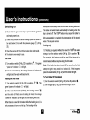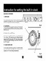
1
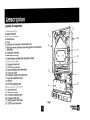
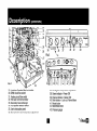
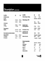
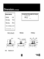
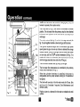
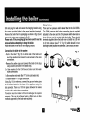
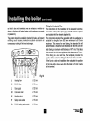
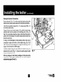
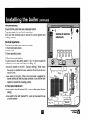
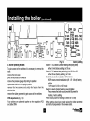
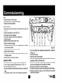
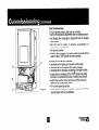
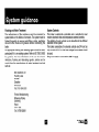
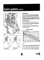
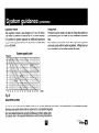
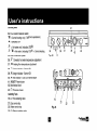
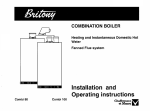
COMBINATION BOILER
Heating and lnstantane~us
eater with TSS@
Domestic Hot
Fanned Flue system
Calydra 80
Installation and
Operating instructions
Calydra 100
These instructions are suitable for the following boilers :
Calydra 80
Calydra 100
CUSTOMER CARE
Chaffoteaux et Maury Ltd , as a leading manufacturer of domestic and commercial water heating appliances, as well as domestic unvented direct and indirect
storage cylinders, is committed to providing high quality products and a first class after sales service. If it is necessary to contact an engineer, then telephone your
local Chaffoteaux Service Centre. The number can be obtained from the leaflet enclosed with your appliance or by telephoning the Chaffoteaux Customer Services
Department at Telford
Advice on installation or servicing can also be
contacting the Chaffoteaux Customer Services Department
CUSTOMER
SERVICES
DEPARTMENT
Tel 01952 222288
Fax 01952 260915
GUARANTEE
The manufacturer’s guarantee against faulty manufacture or materials for the cylinder and secondary heat exchanger is 5 years, from the date of purchase. For the
boiler, electrical components, thermal controls and safety valves it Is for 12 months. from the date ot purchase.
The guarantee will be rnvalrdated if the factory frtted DHW pressure relief valve is tampered with or removed The Manufacturer or Distributors cannot be held
responsible for any damage howsoever caused and which is a consequence of the removal or tampering
The guarantee may also be invaltdated if the appkance is not installed by a competent person in accordance with the recommendations made herein, current
standards, regulations or in a manner not approved by the manufacturer, modified in any way, subjected to frost, misuse or neglect and that factory fitted parts have
had unauthorised repairs or replacemenfs carned out Evidence of purchase and the date ot supply must be made available at the time of any claim. The guarantee
is only vakd for appkances installed in the UK
To asstst us In providing you with an efficient after sales service, please return the guarantee registration card enclosed with the cylinder without delay.
STATUTORY REQUIREMENTS
The mstallatton of this appliance must be carried out by a CORGI Registered person or other competent person and in accordance with the requirements of the Gas
Safely (Installatron and Use) Regulations.
In addrtion, the installahon must also comply with the current byelaws of Local Water Undertakings, Building Regulations, IEE Wiring Regulations, Local Authority
Building Standards (Scotland) Regulations and the Safety Document 635 The Electricity at work Regulation,
It should also be carried out in accordance with current editions of the following British Standards Codes of practice: BS 6891, BS 5440 parts I and 2, BS 5449 part
1, BS 7593, BS 6798, BS 5546, BS 4814, BS 7074 part 1 and 2, BS 7671 and BG DM2
If there is a possibility of the incoming mains water pressure exceeding 7 bar then a suitable pressure limiting valve must be fitted.
Precautions During servicing, keep the dust generation to a minimum and avoid inhaling any dust and contact with the skin and eyes, Normal handling and use will
not present any discomfort, although some people with a history of skin complaints may be susceptible to irntation. When disposing of the lining, ensure that it is
securely wrapped and wash hands after contact
q
chaffoteallx~
--iA
Page
Page
CUSTOMER CARE.. ....................................................................
Guarantee.. ..................................................................................
Statutory Requirements.. .............................................................
Contents.. .....................................................................................
INTRODUCTION..
........................................................................
3
3
3
4
5
DESCRIPTION.. ...........................................................................
..................................................
LOCATION OF COMPONENTS
SPECIFICATIONS..
......................................................................
DIMENSIONS.. .............................................................................
OPERATION ...............................................................................
DOMESTIC HOT WATER MODE ...............................................
CENTRAL HEATING MODE.. .....................................................
INSTALLATION
..........................................................................
PLANNING ..................................................................................
LOCATION .................................................................................
INSTALLING THE CALYDRA ....................................................
INSTALLATION ...........................................................................
POSITIONING THE BOILER ON THE WALL.. ............................
CONNECTING THE BOILER TO THE SYSTEM.. ......................
FITTING THE HORIZONTAL FLUE.. ..........................................
MAKING THE ELECTRICAL CONNECTIONS
...........................
PRE-COMMISSIONING..
............................................................
Electrical Adjustments ...........................................................
1. Room thermostat options.. ................................................
2. Pump Speed Adjustment.. ................................................
3. Burner operating modes :. .................................................
COMMISSIONING..
.....................................................................
DHW.. ....................................................................................
Central Heating .....................................................................
6
6
8
.22
LIGHTING THE BOILER .............................................................
...........................................................
23
POST COMMISSIONING..
THE
HOUSEHOLDER..
............................
.23
HANDING OVER TO
.24
SYSTEM GUIDANCE.. ................................................................
FLUE ...........................................................................................
.24
VENTILATION.. ...........................................................................
.25
.25
GAS SUPPLY.. ............................................................................
.25
ELECTRICAL SUPPLY.. .............................................................
FLUSHING AND WATER TREATMENT ...................................... 26
SYSTEM CONTROLS . . . . . . . . .. .. . . . .. .. . .. . . . . . .. .. . . . . .. .. . . . . . .. .. . . . . .. .. . . . .. .. .. .26
.27
BY PASS AND PUMP .................................................................
.28
EXPANSION VESSEL.. ...............................................................
.28
FILLING POINT.. .........................................................................
28
MAINTENANCE..
.........................................................................
10
.12
.12
.I4
.15
.15
..15
.15
.15
15
.18
.17
.18
.20
.20
.20
.20
.20
.22
.22
.22
.29
USER’S INSTRUCTIONS ...........................................................
.29
Control panel ...............................................................................
.29
Isolating Taps ..............................................................................
SWITCHING ON.. ........................................................................
.30
.30
Hot Water ....................................................................................
.30
Heating and Hot Water.. ..............................................................
.30
Heating Only.. ..............................................................................
.30
To Turn Boiler Off Completely.. ...................................................
INSTRUCTIONS
FOR SETTING THE BUILT IN CLOCK.. ........ .31
.31
MECHANICAL TIMER.. ...............................................................
.31
1. General Layout.. ......................................................................
2. To Set the Time.. .....................................................................
.31
3. To Set the “On” and “Oft” Times.. ............................................
.31
4. To Select Function MODE .. .. . . . .. . .. . . . . . .. .. . . . . . . .. .. . . . .. .. . .. . .. .. . . . . . .. .. .31
By combining their modern highly efficient low water content fanned flue combination boiler concept and the brand new
TSS@‘Temperature Stabilised System”, Chaffoteaux et Maury have created a whole new concept.
CALYDRA
This unique combination is able to provide the user with hot water immediately at the outlet of the appliance and stable
temperatures at both extremely low flow rates or when several taps are opened together.
The TSS@ is a 5 litres, independently controlled mini unvented storage cylinder, powered by a 3 kW coil. It works in conjunction
with the Chaffoteaux et Maury low pressure instantaneous domestic hot water system.
The CALYDRA, as well as providing hot water, provides central heating. The boiler is designed for sealed systems only. A two
speed circulating pump, diverter valve, expansion vessel as well as a pressure gauge and safety valve are included within the
boiler.
The CALYDRA provides the advantages of mains pressure hot water to taps and showers. Supplied directly from the main
water supply the CALYDRA does not need a separate feed cistern or vent pipe in the loft space.
The CALYDRA has been tested and approved by the WRc as meeting with the requirements of the water by-laws scheme.
The boiler has been tested and approved to carry the CE mark.
The CALYDRA can be installed with the standard horizontal flue, raised horizontal, concentric vertical, twin pipe flue or seduct
arrangements. Adapters, bends and other accessories are available on request.
The boiler is packed in TWO cartons:
1. The boiler.
2. The flue assembly and fixing kit.
Location of components
1. Flue hood with fan
2. Sealed chamber
3. Gas valve assembly
4. Electrical box
5. Pump
6. Automatic air separator and automatic vent
7. Multi-gas burner assembly comprising ignition and ionisation
electrodes
8. Combustion chamber
9. Main heat exchanger
10. Steel chassis complete with expansion VE
11. Air pressure switch
12. Overheat thermostat
13. TSS @J(mini cylinder)
14. Central heating control thermistor
15. Three way valve
16. Expansion vessel connecting tube
17. By pass adjustment screw
18. By pass
19. CH Flow isolating valve
20. Domestic hot water outlet
21. Gas service tap
22. Water service tap
23. CH Return isolating valve
25. Pressure relief valve
27. DHW pressure relief valve
28. TSS@ control thermistor
Fig.1
29.
30.
31.
32.
33.
34.
35.
36.
Location of heating filter (not visible)
DHW circuit flow switch
Heating circuit flow switch
Hot water control thermistor
Secondary heat exchanger
Four position selector switch
User’s instruction panel.
Domestic hot water temperature adjustment
37.
38.
39.
40.
41.
42.
43.
Heating flow temperature adjustment
Green indicator - Power ON
Orange indicator - Burner ON
Red indicator - Lock out / flame failure
Reset button
Mechanical clock
Pressure gauge
SPEClFlCATloNS
CALYDRA
Appliance
80
category
C/H 81 DHW
C/H circuit pressures
Min operating
Max operating
CALYDRA
Natural gas G20
Gas rate
Maximum
25.9 kW
88392 Btuh
31.1 kW
106138 Btu4-1
23.25 kW
79347 Bhuh
inlet pressure
28.0 kW
Nominal
95558 lBu4-1
0.7 bar
10 lb/in2
0.7 bar
10 lb/in2
2.5 bar
36.3 lb/in2
2.5 bar
36.3 lb/in2
Burner pressure
Nominal
Burner injector and restrictor
Natural gas G20
l/3 restrictor
Z3 restrictor
DHW specific flow rates for 10 min
Q 30 deg C rise
11.5 Vmin
13.9 Vmin
Q 35 cieg C rise
2.54 gal/min
9.86 Umin
3.06 gai/min
11.91 Umin
PROPANE
2.17 gallmin
2.62 gailmin
Gas rate
Maximum
0.1 bar
1.45 lb/in2
0.1 bar
1.45 lb/in2
7 bar
100 lb/in2
7 bar
100 lb/in2
DHW circuit pressures
Min operating
Max operating
Flow limiter
Compartment
rate
ventilation
80
Cat ii 2H 3+
& DHW
Heat input C/H
Maximum
Heat output
Maximum
100
Cat ii 2H 3+
8 Vmin
not
10 Vmin
required
100
2.74 m31h
97 ft3lh
3.29 m3/h
116ft31h
20 mbar
8inwg
20 mbar
8inwg
11 mbar
4.4 in wg
12.8 mbar
5.12 in wg
1.23 mm
2.60 mm
6.7 mm
1.28 mm
2.9 mm
no restrictor
2.00 kg/h
4.41 lb/l-u
2.42 kg/h
5.34 Ib/hr
37 mbar
14.8 in wg
37 mbar
14.8 in wg
35 mbar
14 in wg
30.4 mbar
12.16 in wg
diameter
LPG G31
inlet pressure
Nominal
Burner pressure
Nominal
80
CALYDRA
BUTANE
100
Gas rate
Maximum
2.04 kg/h
4.50 lb/h
inlet pressure
Nominal
11.2 in wg
28 mbar
11.2 in wg
Burner pressure
Nominal
Burner injector and restrictor
Butane LPG G30
l/3 restrictor
213 restrictor
26.7 mbar
10.7 in wg
CALYDRA
Safety discharge
- Heating
2.45 kg/h
5.40 lb/h
Safety discharge
- DHW
28 mbar
Expansion
Pre-charge
LPG G30
24 mbar
9.6 in wg
vessel
pressure
Net capacity
Adjustable
0.7 mm
1.75 mm
4.9 mm
0.76 mm
2.0 mm
100
2.5 bar
2.5 bar
36.25 iblin2
36.25 lb/in2
7 bar
100 lb/in2
7 bar
0.7 bar
0.7 bar
100 lb/in2
9.4 lb/in2
9.4 lb/in2
5.44 itr
5.44 itr
by-pass
150 i/h
150 i/h
0.55 gai/min
0.55 gai/min
480 i/h
1.76 gai/min
480 iih
1.76 gal lmin
SUPPlY
Consumption
23fiv5oi-k
23Ov5OHz
155w
155w
Protection
IP 44
iP44
Fuse no 1
2A
2A
Fuse no 2
1.25A
1.25A
External
24V
24V
Minimum
diameter
at 2.5 bar
80
flow rate
Maximum
flow rate
Electrical
characteristics
6.7 mm
controls
Outer case dimensions :
-Width :
440 (minimum space required 450)
850
- Height :
- Depth :
380
Weights
With packaging
-Calydra 80 :
Calydra 100 :
:
49.0 kg
49.5 kg
Without packaging
-Calydra 80 :
-Calydra 100 :
:
46.5 kg
47.0 kg
Liit weight :
-Calydra 80 :
-Calydra 100 :
41.5 kg
41 .O kg
1po
Tails diameter
-
J
Heating flow
022mm
K
D.H.W. flow
015mm
L
Gas supply
022mm
M
Cold water inlet
015mm
N
Heating return
022mm
P
Safety valve outlet
015mm
a,:
I : ‘.
ji -. --_
-
i66
Safety valve
center line
All dimensions in mm
Fig. 4
Minimum clearances
:
- Both sides
5mm
- Above casing
170 mm
- Below casing
200 mm
- Front ( for servicing)
500 mm
- Front (in operation)
5 mm
TYPE C12, C42 or C22
T
155
*
.<,:
:*.*.: -----_-___------- y-m,.-+
'%.xx
4
.Z.S.2.
..
149
l
-_- -A-
r+%
Fig. 5
Dimensions in mm
The Calydra 80 and 100 are suitable for the 3 flue types :
l typeC12orC42
l type C 22
l typeC32xxorC32xy
TYPE C32 xx
TYPE C32 xy
ini
Domestic
Hot Water Mode
To be able to supply hot water, the selector switch (34 fig.
6) must be in either on ,,? or ‘1111
,i position. This will be
confirmed by the green indicator light 0 (38 fig. 6).
The hot water temperature in the mini cylinder can be
adjusted between 40°C and 60°C using control knob (36
fig 6).
When a tap or shower is turned on and the flow of mains
water is above 2 litres per min., it will activate the DHW
flow switch 30 fig 7 and allow the 3 way valve (15 fig. 7)
to move to the DHW position. The pump can now
circulate
primary water heated by the main heat
exchanger through the secondary heat exchanger.
The safety solenoid (3a fig. 7) and the first stage solenoid
(3b fig. 7) open together to allow gas to the burner. The
ignition sequence begins and a continuous high speed
spark ignites the gas. As soon as a flame is detected the
orange indicator bulb 0 (39 fig. 6) will light and the
second stage solenoid (3c fig. 7) opens to allow the full
gas rate. If a flame is not detected, after 8 seconds, the
safety solenoid and the first stage solenoids close and
shut off the gas. The red lockout indicator bulb 0 (40 fig.
6) will light.
dependant upon to the position of the DHW temperature adjustment
knob (36 fig. 6). This system anticipates
the changes of
temperature in the secondary heat exchanger and ensures accurate
temperature regulation.
When the tap is closed the burner is extinguished and the pump
runs on for 10 seconds (unless the mini cylinder thermistor is calling
for heat, in which case the burner will remain on at a low rate and
the pump will continue running until the mini cylinder thermistor is
satisfied). The boiler will now stay in the hot water mode for 30
seconds to be ready for a subsequent draw off (this can be set to 3
minutes if required. See Maintenance and Service Guide).
Priority is given to a demand for hot water. This will interrupt the
central heating for the duration of hot water delivery or recovery of
the mini cylinder.
Over 2 Vmin, the domestic hot water temperature is When the boiler has been in standby in Hot Water Mode for some
controlled by the hot water control thermistor (32 fig. 7) time or when drawing DHW at flow rates of less than 2 Vmin the
and the heating control thermistor (14 fig. 7), but
temperature in the mini cylinder will eventually decrease and the
TS@ control thermistor will call for heat. Bringing the pump and
burners to operate, this is quite normal.
The 3 way valve (15 fig. 7) will move to the domestic hot water
position. The hot water from the primary circuit is then diverted
to heat the mini cylinder via the coil and the secondary heat
exchanger.
2
3c
7a
7b
3b
3a
10a
12
4
32
The safety solenoid (3a fig. 7) and the first stage solenoid (3b
fig. 7) open together to allow a low rate of gas to the burner.
The ignition sequence begins and a continuous high speed
spark ignites the gas. As soon as a flame is detected the orange
indicator bulb ID (39 fig. 6) will light and the burner will remain
on low rate until the TSS@ control thermistor (28 fig. 7) is
satisfied. If a flame is not detected, after 8 seconds, the security
and first stage solenoids close and shut off the gas.
The red lockout indicator bulb 9; (40 fig. 6) will light.
The hot water flow temperature is controlled
circuit control thermistor (14 fig. 7).
by the primary
When the cylinder thermistor
is satisfied, the burner is
extinguished and the pump remains running for 10 seconds at
low speed.
The boiler will now stay in the hot water mode for 30 sec. (this
can be set to 3 minutes if required. See Maintenance and
Service Guide).
Priority is given to a demand for hot water or reheating the mini
cylinder.
Central Heating Mode
To be able to supply heating, the selector switch (34 fig. 6)
must be in ‘1111
$ (heating and hot water position) or ‘fill
(heating only position).This will be confirmed by the green
indicator light 0 (38 fig. 6).
When there is a demand for heating (either from a room
thermostat, the built-in clock or an external programmer) and
the boiler temperature control is calling for heat.
The pump starts and at a flow rate of 4 Itr/min the central
heating flow switch operates allowing the ignition sequence to
begin.
The safety solenoid (3a fig. 7) and the first stage solenoid (3b
fig. 7) open together to allow gas to the burner.
The ignition sequence begins and a continuous high speed
spark ignites the gas.
As soon as a flame is detected the orange indicator bulb 0
(39 fig. 6) will light.
After 45 seconds the second stage solenoid (3c fig. 7) opens
to allow the full gas rate.
If a flame is not detected, after 8 seconds, the security
solenoid closes and shuts off the gas.
The red lockout indicator bulb 0 (40 fig. 6) will light.
The central heating flow temperature is controlled by the
heating control thermistor (14 fig. 7).
The boiler has been designed to minimise cycling and will not
attempt to relight for at least 3 minutes after the heating
control thermistor has been satisfied (this can be set to 30
seconds if required. See Maintenance and Service Guide).
When the built-in clock, room thermostat
and external
programmer are satisfied, the burner will switch off and the
pump will remain running for a further 3 minutes. (this can
also be set to 30 seconds if required. See Maintenance and
Service Guide).
NB It is possible to override the 3 minute delay
the RESET button (41 fig. 6).
by pressing
INSTALLING
Planning
Please ensure that you are familiar with the installation
requirements as well as the relevant British Standards and
Statutory Regulations (see page 3) before commencing work.
Location
The CALYDRA can be installed on any suitable internal wall.
Provision must be made to allow the correct routing of the flue
and siting of the terminal to allow the safe and efficient
removal of the flue products. The appliance may be installed
in any room, although reference must be made to the IEE
regulations if it contains a bath or shower. A compartment or
cupboard may be used provided that it has been purpose-built
or modified for the purpose. It is not necessary to provide
permanent
ventilation
for cooling purposes.
Detailed
recommendations are given in BS 5440 pt 2. If it is proposed
that it is installed in a timber framed building then reference
must be made to British Gas Document DM2, or advice
sought from CORGI.
q
THE CALYDRA
Installation
The installation
kit included with the flue components
comprise following items :
- Hanging bracket
- A paper template (showing the dimensions of the boiler with
5 mm side clearances and fitting instructions and on the
reverse, the fixing positions for the spacer bracket)
- Connection tails
- Screws and wall plugs
- Connection washers
- Pre-piping jig
- Installation and Operation manual
Positioning the boiler on the wall.
The paper template can be used to ensure the correct
positioning of kitchen cabinets etc.
The paper template is fixed to the wall and used to locate the
position of the hanging bracket, the centre for the flue hole
and, if required, the fixings for the pre-piping jig.
If there is a requirement to pass the piping behind the
boiler, it will be necessary to fit a spacing bracket. This is
available as an optional accessory. The standard paper
template shows the positions for the spacing bracket
fixing screws.
chaffoteaux~
a-u
Drill and plug the wall and secure the hanging bracket using
the screws provided (refer to the paper template drawings).
Remove the boiler from its packaging as shown in (fig. 8) and
remove the outer case as shown in (fig. 9).
Please note: If the pre-piping jig has been used it must be
removed before attempting to hang the boiler.
Place the boiler on the wall on the hanging bracket.
Safetv Valves
There are two pressure relief valves fitted to the CALYDRA.
The DHW pressure relief valve connecting pipe is supplied
attached to.the valve and the CH pressure relief valve tube is
clear silicone and is packed with the boiler. They should
terminate together below the boiler over a tundish or a 28 mm
to 22 mm reducer (see P 17, fig 10) which should in turn
discharge safely outside the premises. Care should be taken
Connecting the boiler to the system
- Push in the tabs P (fig 10) on either side of the boiler and
pivot the electrical box forward to gain access to the valve
connections.
- Remove the yellow caps and connect the boiler to the taps
using washers provided in the plastic bag.
3 x fibre washers for the C/H flow and return and hot water
outlet connections
1 x fibre washer and mesh filter “F” for the cold water inlet.
1 x rubber washer “R” for gas connection.
Using (fig. 10) for reference, connect the gas and water pipes
to the valves located at the base of the appliance using the
tails provided. There is a 190 mm space between the valves
and the wall to make these connections.
Provision must be made to fill and recharge the system
pressure. This can be achieved using a filling loop or other
methods approved by the local water authority.
f
Fig. 8
Fig. 9
q.
chffoteaux~
,-AA
so that it does not terminate over an entrance or window or
where a discharge of heated water could endanger occupants
or passers by.
The system should be carefully checked for leaks, as frequent
refilling could cause premature
system corrosion
or
unnecessary scaling of the heat exchanger.
Fig. 10
Heating flow
022mm
K
D.H.W. flow
015mm
L
Gas supply
022mm
M
Cold wafer inlet
015mm
N
Heating return
022mm
P
Safety valve outlet
015mm
Q
D.H.W. safety valve outlet
015mm
J
Fitting the Horizontal Flue
The instructions for the installation of the elevated horizontal,
concentric vertical, biflux (twin pipe) and SE duct flue options
are included with the relevant adapter kits.
The horizontal standard flue supplied with the appliance is
suitable for lengths from 300 mm minimum to 610 mm
maximum. This means for rear flueing, the standard kit will
accommodate a maximum wall thickness of 490 mm, and for
side flueing a maximum wall thickness of 477 mm. This takes
into account the minimum appliance side clearances of 5 mm.
If the fixing is a rear exit flue, the template provides the
position of the centre for drilling the flue hole with a core drill.
If the flue is a side exit installation then calculate the position
of the hole with a slope, away from the boiler, of 5 mm / metre
to the terminal.
Making the Electrical
Connections
Push in the tabs (P fig. 11) on either side of the boiler and pivot the
electrical box forward to gain access to the electrical connections.
Undo the two retaining screws (A fig. 1 l), remove cover (B fig. 11)
and remove cable clamp.
Connect the live and neutral wires to the multipin plug leaving
sufficient earth wire to connect to the earthing point. (B fig. 12)
Note: The connections should be made so that should the lead be
pulled from its anchorage, the current carrying wires become taut
before the earth wire.
If using a room thermostat or other external control, they can be
connected in place of the link on the multipin plug. (fig. 12).C
Note: Use only controls designed for voltage free switching or 24V
supply. Do not connect to a 230V supply.
Connect multipin plug into the socket on the pcb (D fig. 12)
attached to the cover (B fig. 11). Secure the cable using the cable
clamp and replace the cover.
NB Any changes to the factory settings on the pcb can be
made before replacing the electrical box cover (see electrical
adjustments pages 20 and 21).
Fig. 11
Making the Electrical Connections
(continued)
t
l
i
3 amp.
Mains
q.
Room
Thermostat
Pre-commissioning
Ensure that the system has been adequately flushed.
Purge gas supply of air and test for soundness.
Carry out final electrical tests to ensure the correct polarity and
earthing continuity.
Electrical Adjustments
There are three adjustments that can be made:
1. Room thermostat options
2. Pump speed
3. Burner operating modes :
1. Room thermostat options
To gain access to the setting switch (1 fig. 13) pivot forward the
electrical box cover and remove the cover (B fig. 11)
- move the switch to the left - (factory setting). When room
thermostat is satisfied the burner switches off and the pump over
runs for 3 min.
- move switch to the right - When room thermostat is satisfied the
burner switches off and the pump continues to run until the main
selector is turned from a heating position.
2. Pump Speed Adjustment
- move switch to the left (marked GV) - pump on high speed (factory
setting)
- move switch to the right (marked PV) - pump on low speed for use
on small systems
3 min
3 min
TUR
Pmin
3. Burner operating modes :
To gain access to the switches it is necessary to remove the
facia:
remove the main case
pivot the electrical box forwards
remove the pressure gauge clip noting its position
replace elecrical box in its upright position
remove the two screws and unclip the fascia from the
electrical box
remove the rubber grommet to gain access to the switches
PCB adjustments (fig. 14) :
Four switches are gathered together on the regulation PCB
and labled SW4.
/
IL
factory setting
Fig. 14
Switch 1 TAC selects Central heating anticycling delay
either 3 min (factory setting) or 30 see
Switch 2 TIC selects delay switching from DHW to C/H
either 30 see (factory setting ) or 3 min
Switch 3 selects the modulation of the Burner.
NOR means normal modulation (off - l/3 - full on) factory
setting
TUR means Full On or Off mode
Switch 4 selects Central heating power limitation
Pmax means the boiler could provide full power for
heating - factory setting
Pmin means power for heating is limited to 113 only
When settings have been made replace the rubber grommet
and refit all components in the reverse order.
DHW
Open the main cold feed valve.
l
Open all hot taps to purge DHW system.
l
Check for water soundness.
l
Central Heating
Open flow and return valves on the boiler.(l9 and 23
fig. 15)
l
Open the automatic air vent (6 fig. 16)
l
Fill system and vent radiators.
l
Set system pressure and remove filling loop.
l
Check for leaks.
l
Manually check pump is free to turn.
l
Switch on electrical supply.
l
Turn selector switch (34 fig. 16) to heating only or heating
and hot water position.
l
Allow pump to run for several minutes.
l
Isolate electrical supply.
l
Drain boiler and check water filter (29 fig. 2) for
installation debris.
l
Replace filter and recharge system.
l
Lighting the Boiler
Connect gas pressure gauge to test point ( 45 fig. 16).
l
Turn on the gas supply and boiler gas tap ( 21 fig. 15.
l
Ensure electrical supply is on.
l
Ensure all external controls and built clock are calling for
heat.
l
Turn selector switch ( 34 fig. 16) to heating only position.
l
Fig. 15
14 Turn the heating flow temperature adjustment to maximum
(37 fig. 16).
l
The boiler will light.
l
Allow the boiler to heat system.
l
Check the inlet gas pressure (working pressure) while boiler
operating. (Refer to technical data).
l
Check the operation of the boiler controls and safety
devices.(see separate servicing leaflet for details)
l
Set the by pass (Refer to system guidance).
l
Re-flush the system to remove any dissolved oils and fluxes.
l
Recharge system pressure and introduce any water
treatment as required.
Post Commissioning
l
Ensure system pressure has been set correctly.
l
Set DHW temperature adjustment knob to required position
l
Set heating flow temperature adjustment knob to required
temperature.
l
Set the built in clock or external
programmer
to
householder’s requirements.
l
Set external controls.
l
Switch boiler to domestic hot water position and draw off hot
water to allow TSS@ cylinder to heat up quickly.
K6
Fig. 16
Handing Over to the Householder
Demonstrate the lighting and operation of the boiler.
l
Demonstrate how to maintain the system pressure.
l
Demonstrate the operation and settin of the built-in clock.
l
Explain that the reheating of the TSS 8 cylinder may bring
the boiler on unexpectedly except in heating only position.
l
Explain the need for annual servicing and that it must be
carried out by a competent person.
l
Fill out and register guarantee.
l
Leave users instructions, installation manual and all other
documentation with the householder.
l
Flue
The boiler must be installed so that the flue terminal is
exposed to the free passage of external air at all times. It
must not be allowed to discharge into another room or
space such as an outhouse or closed lean-to. The
minimum acceptable clearances are shown below:
- A Directly below an opening, window, etc ... .. . . . .. 300 mm
- B Below gutters soils pipes or drain pipes . .. . . .. . . .. . . 75 mm
- C Below eaves . . .. . .. .. . .. .. . . .. . .. . . .. . .. . . .. . . .. .. .. . . . . .. . . .. . .. . 200mm
- D Below balconies or car port roof . . .. . . . .. .. . . .. . .. . . .. 200 mm
- E From a vertical drain pipe or soil pipe . .. . . .. . . .. . .. . . 75 mm
- F From an internal or external corner . .. .. . . . . .. . . .. . .. 300 mm
- G Above ground roof or balcony level ... .. . . .. . . .. . .. 300 mm
- H From a surface facing the terminal . . .. . .. . . .. . . .. .. 600 mm
- I From another terminal facing the terminal....... 1200 mm
- J From an opening into the dwelling when
under a car port . . .. . .. . . .. . .. . .. . . .. . .. . . .. .. . . ... . .. . .. . . . .. 1200 mm
1500 mm
- K Vertically from a terminal on the same wall
- L Horizontally from a terminal on the same wall 300 mm
- M fixed by the flat roof ubbink rolux 4GM flue terminal
- N fixed by a pithed roof ubbink rolux 4GM flue terminal
Fig. 17
Ventilation
The room in which the boiler is installed does not require specific
ventilation. IF IT IS INSTALLED IN A CUPBOARD OR
COMPARTMENT
PERMANENT VENTILATION
IS NOT
REQUIRED FOR COOLING PURPOSES. If vents are installed,
they must communicate with the same room or be on the same
wall to outside air.
Gas Supply
The gas installation
and soundness testing must be in
accordance with the requirements of BS 6891 .The boiler
requires a 22 mm supply, Ensure that the pipe size is
adequate for the demand including other gas appliances on
the same supply.
Electrical
Supply
The appliance requires an earthed 230V - 50 Hz supply and
must be in accordance with current I.E.E. It must also be
possible to be able to completely isolate the appliance
electrically. Connection should be via a 3 amp fused doublepole isolating switch with contact separation of at least 3 mm
on both poles. Alternatively, a fused 3 Amp. 3 pin plug and
unswitched socket may be used, provided it is not used in a
room containing a bath or shower. It should only supply the
appliance.
System Pressure
The boiler is suitable for sealed systems only. The maximum
working pressure for the appliance is 3 bar. All fittings and
pipework connected to the appliance should be of the same
standard.
Flushing and Water Treatment
The performance of the appliance could be impaired by
system debris or the effects of corrosion. The system must be
flushed thoroughly to remove metal filings, solder, machining
oils and other fluxes and greases before connecting the
boiler.
An appropriate flushing and descaling agent should be used,
particularly if it is an existing system. Refer to BS 7593 (1992)
for guidance. For more information on the use of corrosion
inhibitors, flushing and descaling agents, advice can be
sought from the manufacturers of water treatment products
such as:
Betz Dearbon Ltd
Foundry Lane
Widnes
Cheshire
WA8 8UD
Tel: 0151 424 5351
Fernox Manufacturing
Britannica Works
Clavering
Essex
CBll 4QZ
Tel: 01799 550811
System Controls
The boiler is electrically controlled and is suitable for most
modern electronic time and temperature external controls.
The addition of such controls can be beneficial to the efficient
operation of the system.
The boiler connections for external controls are 24V and so
only controls of 24V or that have voltage free contacts should
be used.
They must not be connected to 230 V supply.
By pass and Pump
The boiler is fitted with a pre-adjusted by pass. Although
adjustment is not normally necessary, the by pass can be
reset by turning screw (17 fig. 18) clockwise to open the bypass using the chart below for guidance. It is a l/4 turn from
fully closed to fully open.
If used on a system with thermostatic radiator valves, the
flow rate, through the system, with the thermostatic valves
closed should be at least 100 I/hr.
The chart below indicates the residual head of the pump
available for the system.
Head and flow rate available
mH2
5
Fig. 18
detail of setting :
4
3
2
1
0
100
100
300
400
500
600
700
BOO
900
DCbt
1000 h
Fig. 19
of screw head on - :
by pass shut (factory setting)
Cut
“GV
“GV
“PV
“PV
Cut of screw head on + :
by pass open
q
- bp -I’ means : Pump in high speed and by-pass closed
- bp +” means : Pump in high speed and by-pass open
- bp -” means : Pump in low speed and by-pass closed
- bp +” means : Pump in low speed and by-pass open
chaffoteaux~
-=-AA
Expansion Vessel
The expansion vessel is pre-charged to 0.7 bar (10 Iblin2).
The vessel is suitable for systems up to 145 litres capacity.
For systems of greater capacity an additional expansion
vessel will be required. Refer to the chart below and BS 7074
pt 1 or BS 5449.
Pressure
2,o
13
128
1.7
’
System capacity
Filling Point
Provision must be made to be able to charge the system on
commissioning and to make up any subsequent pressure
loss.
The method of connection must utilise approved equipment
and must comply with the water regulations. A filling loop can
be so installed as to be hidden beneath the boiler.
chart
1-6
1,5
l-4
I,3
12
I,1
1.0
0,9
0,8
0,7
Litres
Fig. 20
MAINTENANCE
In order to ensure that the CALYDRA continues to operate efficiently and safely, it is essential that it is maintained annually.
Servicing and repairs should only be carried out by a competent engineer.
Any part replaced should be genuine Chaffoteaux et Maury spare parts.
For details refer to the separate Maintenance and Servicing Instructions.
Control panel
34. Four position Selector switch
‘Ii11 = Central heating only ( TSS@ not operational )
l
= Switched OFF
F
= Hot water only ( including TSS@ )
z
9111
= Hot water
( including TSS@ ) + Central heating
35. User’s instruction panel.
36. &= Domestic hot water temperature adjustment
37. ‘Ill1 Heating
38. 0
Fig. 22
35
flow temperature adjustment
Green indicator - Power ON
39. P Orange indicator - Burner ON
40. 0 Red indicator - Lock out I flame failure
41. “RESET” Reset button
42. Mechanical clock
43.0
Pressure gauge
Isolating Taps
19.
21.
22.
23.
CH Flow isolating valve
Gas service tap
Water service tap
CH Return isolating valve
/ iv \
lb
/
21
Fig. 23
I
22
\
23
Switching
on
1) Check that the gas service tap is opened at the gasmeter
and main power is on.
2) Check that pressure in central heating system is above 0.7
bar and below 2.5 bar with the pressure gauge 0 (43 fig.
23).
3) Open the gas tap (21 fig. 23) by turning from right to left.
4) The boiler is now ready to use.
Heating only
1) If heating is required without the need for TSS@ hot water
storage, turn the selector switch (34 fig. 22) to position ‘1111.
For example, this feature would be used if the house is to
Hot Water
1) Turn selector switch (34 fig. 22) to position fi
“power on” indicator 0
interrupted momentarily while the hot water is being delivered.
The boiler will switch back automatically to heating when the
tap is turned off. The TSS@ feature may cause the boiler to
light unexpectedly to maintain the temperature of the stored
water. This is quite normal.
. The green
will light.
2) Turn on a hot water tap, the orange “burner on” indicator &
will light and the water will become hot.
Heating and Hot Water
The
1) Turn selector switch (34 fig. 22) to position fl ‘1111.
green “power on” indicator 0 will light.
3) If the room thermostat (if fitted), the heating control ‘III1
and the clock (if fitted) are all calling for heat, the orange
“burner on” indicator 8 will light and the heating will be on.
When there is a need for hot water while the heating is on, it is
only necessary to turn on a hot tap. The heating will be
remain heated without anyone using the hot water.
Note: If the boiler has been turned off for some time the first
attempt to light it may result in a lockout 9 . If this happens
press the reset button (41 fig. 22) and the boiler will light.
To Turn Boiler Off Completely
1) Turn the selector switch (34 fig. 22) to the off position 0.
2) Turn the gas tap (21 fig. 23) from left to right “STOP”.
MECHANICAL
PROGRAMER
1. General layout
The mechanical clock covers a 24 hour period. Each tappet
represents 20 minutes (A fig. 25). An override switch is
located on the right hand side of the clock (B fig 25).
Fig. 24
2. To set the time
To set the time of day, grasp the outer edge of the dial and
turn slowly clockwise until the correct time is lined up with the
arrow (C fig. 25).
3. To Set the “On” and “Off” times
The clock uses a 24hours system. e.g. 8 =8.00 am and
18 = 6.00 pm. “ON” periods are set by sliding all tappets
between the “ON” time and the “OFF” time to the outer edge
of the dial.The tappets remaining at the centre of the dial are
the “OFF” periods.
4. To select function
mode
Put the selector switch (6) to symbol 0 to control the boiler
by the clock. Put the switch (B) to “1” to select permanent
operation or to “0” to turn heating off permanently.
B
Fig. 25
-----a
u
Chaffoteaux et Maury are continuously improving their products and therefore reserve the right to change specifications without
prior notice and accepts no liability for any errors or omission in the information contained in this document.
Q Chaffoteaux et Maury 1998
Chaffoteaux et Maury Ltd
Trench Lock
Trench
Telford
Shropshire
TFl4SZ
Tel: 01952 222727
Fax: 01952 243493
ESP 040 January 1999