1
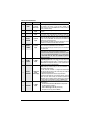
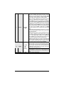
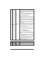
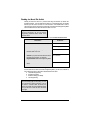
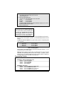
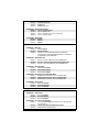
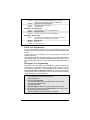
A U T O M A T I C T R A N S M I S S I O N R E M O T E S T A R T E R AS-2510 TW Installation Guide A note concerning the battery inside the transmitter: Depending on the usage of the transmitter, the battery can last anywhere between 3 to 6 months. When the battery is low, it the transmitter will emit two beeps in a repetitive cycle. At that point you should replace your battery with a new one. That is why we recommend that you keep a spare battery somewhere handy such as the glove compartment. Notice The manufacturer will accept no responsibility for any electrical damage resulting from improper installation of the product, be that either damage to the vehicle itself or to the Unit. This Unit must be installed by a certified technician using all safety devices supplied. Please note that this guide has been written for properly trained Autostart technicians: a certain level of skills and knowledge is therefore assumed. Please review the Installation Guide carefully before beginning any work. Warning This Remote Car Starter is designed for vehicles with an automatic Transmission only. Before installing the Unit, test that the vehicle does not start when the Gear Select Lever is in the “Drive” position. If it starts in gear, install a manual-transmission remote starter system instead. DOC .1.00 – November 5, 2003 Gp CA Lp Manufactured in Canada by Autostart Table of Contents Table of Contents .....................................2 Introduction...............................................2 Included in the Kit .....................................2 Installation Points to Remember...............3 Harness Description .................................4 Flashing the Hood Pin Switch...................9 Tip.............................................................9 Remember:...............................................9 The Programming Assistance Button .....10 Caution ...................................................10 Programming a Transmitter....................10 Before you Proceed................................10 The Transmitter Programming procedure10 Entering Programming Options Mode ....10 Programming Options.............................11 Tach Programming .................................13 About Tach Programming.......................13 Multi-speed Tach Programming..............13 Automatic Tach Programming ................14 Horn Chirp Timing...................................14 Testing.................................................... 14 Closing Up.............................................. 15 Supplementary Information .................... 16 Fifth Relay Output (2nd IGN, ACC or CRANK).................................................. 16 Caution! .................................................. 16 Ignition-controlled Door Locks................ 16 Secure Lock ........................................... 16 Standard Secure Lock............................ 16 Smart Secure Lock................................. 17 Lock Pulse Duration ............................... 17 Engine Run Time.................................... 17 Starter Kill (Installation) .......................... 17 Passive or Active Arming ....................... 17 Resetting the Remote Car Starter .......... 17 Events Logging....................................... 18 Events playback ..................................... 18 Start Failure Codes through the Parking Lights...................................................... 18 Diagnostics – Parking Light Flash Table 19 Introduction This Guide contains all the information relevant and necessary for the installation of the Remote Car Starter. Most of the features of this product are explained in the User Guide. Therefore, if you need detailed information about a feature of the product, we recommend that you refer to the User Guide. Included in the Kit Please carefully read the Installation Guide before beginning the installation, especially the Harness Description section and the Programming Options. It is very important that you familiarize yourself with the programming and the operation of the Remote Car Starter, even if you have already installed a similar Remote Car Starter in the past. There are many innovative features that you may overlook if you do not read this Guide. Prior to the installation, make sure that all the hardware components required to install the system are in the box. The following is a list of components included in the kit: x 1 – Remote Car Starter Control Unit x 1 – FM long-range Transceiver x 1 – multi-channel 5-button Remote Control x 1 – plug-in L.E.D. x 1 – six-pin 14 AWG Harness (Ignition Harness) x 1 – five-pin 18 AWG Harness (Main Harness) x 1 – twelve-pin 22 AWG Harness (Accessories Harness) P. 2 Installation Guide AS-2510 TW x 1 – two-pin 22 AWG Harness (Accessories Harness) x 1 – parts bag: a Hood Pin-switch, a Connector and a Warning Label x 1 – User Guide The plug-in Valet button is no longer included with this Remote Car Starter. INDUSTRY CANADA USER NOTICE: Operation is subject to the following two conditions: (1) this device may not cause interference, and (2) this device must accept any interference, including interference that may cause undesired operation of the device. To reduce potential radio interference to other users, the antenna type and its gain should be so chosen that the equivalent isotropically radiated power (EIRP) is not more than that required for successful communication. FCC USER NOTICE: The manufacturer is not responsible for any radio or TV interference caused by unauthorised modifications to this equipment. Such modifications could void the user’s authority to operate the equipment. Installation Points to Remember Ƈ Make sure that vehicles equipped with an automatic Transmission do not start while in any of the Drive Gears. If the vehicle starts in gear, install a Manualtransmission Remote Starter instead. Ƈ When installing a manual-transmission product on a vehicle with a manual Transmission, always make sure that all Doors will get the Unit out of Ready Mode. Switch the wire used so that it is triggered by all Doors. Ƈ When installing a manual-transmission product on a vehicle with a manual Transmission, make sure that the Parking Brake and Door Switch contacts work properly. Ƈ When working on a vehicle, always leave a window open. Ƈ Never leave the keys in the car. Leave them on a workbench with a window rolled down. Ƈ If possible, remove courtesy light fuse to prevent battery drain. AS-2510 TW Installation Guide Ƈ The PROGRAMMING ASSISTANCE BUTTON (PAB) The PAB is mounted on the side of the Remote Car Starter unit and fulfils the same function as the Hood-Pin Switch. The PAB will spare installers the effort of getting out of the vehicle to access the Hood-Pin Switch. The PAB works only when the Hood is up. Ƈ Inspect vehicle for any body damage or electrical problems Ƈ Always solder and tape all connections. Ƈ Keep the Antenna away from other types of antennas (GPS/OnStar). Ƈ Never install the control unit where it could interfere with normal operation or obstruct service technicians. Ƈ Always use a grommet when running wires into the Engine compartment. Never run wires through bare or sharp metal. Ƈ Do not disconnect the battery on vehicles equipped with air bags and anti-theft radios. Ƈ Never ground the control unit to the vehicle’s steering column. Ƈ Make sure that all the switches and controls operate properly. Ƈ Verify that the vehicle starts and idles properly. Ƈ Make sure that all safety equipment is installed: the Valet Button (if provided), the Hood Switch and the Warning Label. P. 3 Ƈ When wiring in parallel, make sure you isolate each connection with a diode in order to avoid feedback and possible damage. Examples: Wiring a Clutch Bypass and a Transponder Module to the GROUND OUT WHEN RUNNING wire: At the junction point, where the GROUND OUT WHEN RUNNING wire “splits” and connects to each device, a diode is inserted on each of these lines. Multiple or separate Door pin Connections: When joining all Door Pins together to the Door Pin input wire of the Remote Car Starter unit, each wire must be isolated with a diode to prevent feedback. Note: The above examples reflect common situations where diodes are use to isolate connections. Please note that there are numerous other cases where diode isolation is required. Ƈ Always make sure that all external relays or modules added to the Remote Car Starter unit are properly fused and diode isolated. Ƈ On vehicles equipped with daytime running lights, the installer may be unable to see certain programming results since the daytime running lights never go out. Note: The Parking Light Output Relay of the unit gives two clicking sounds for each flash of the lights: one click when the lights would go ON and one click when the lights would go OFF.) Ƈ Parking Light flashes to which the text refers throughout this manual refer to the Parking Light output of the unit, not of the vehicle. Harness Description When connecting a Remote Car Starter, it is important to make sure that the connector with the Ground wire is connected first, before making the 12-volt connections. Should the Unit be powered up before being grounded, there could be serious damage to internal components of the Unit. Be careful not to power up a Remote Car Starter before it is properly grounded. To avoid any accident, it is recommended to pull out the Fuses from their sockets before the installation, and to put them back during the very last steps. 6-Pin Main Ignition Harness Wire Colour A RED B PURPLE C RED D YELLOW P. 4 Function Description Connect to the largest 12 V supply wire at the Ignition Harness. Ensure that the OEM power wire is fused for more than 30 A. (+) 12 V Battery Please note: some of the most recent vehicles have no suitable 12 V source at the Ignition Switch (the 12 V wire is too small to supply the necessary current). In such cases, it is recommended to use the fuse box or the B+ connection on the Battery. (+) Starter output Connect to the Starter wire of the vehicle. The source wire should (30 A) have +12 V with the Ignition Key in the CRANK position only. Connect to the largest 12 V supply wire at the Ignition Harness. Ensure that the OEM power wire is fused for more than 30 A. Please note: some of the most recent vehicles have no suitable (+) 12 V Battery 12 V source at the Ignition Switch (the 12 V wire is too small to supply the necessary current). In such cases, it is recommended to use the fuse box or the B+ connection on the Battery. Connect to the Ignition wire of the vehicle. The source wire should (+) Ignition have +12 V with the Ignition Key in the IGNITION ON (RUN) and output (30 A) CRANK positions. Installation Guide AS-2510 TW E ORANGE F GREEN Warning: at the Ignition Switch of certain vehicles, there may be more than one Ignition wire. Use the 5th relay (Pin F) and extra relays to power up any extra Ignition wires if necessary. Do not jump wires at the Ignition Switch: this would compromise the OEM electrical system. This wire will power the Heater Blower Motor. Usually connected to the Accessories wire of the vehicle. The source wire must have power with the Ignition Key in the IGNITION ON (RUN) position only (no power in the CRANK position). (+) Accessories Warning: at the Ignition Switch of certain vehicles, there may be output (30 A) more than one Ignition wire for powering the Heater Blower Motor. Use the 5th relay (Pin F) and extra relays to power up any extra Ignition wires if necessary. Do not jump wires at the Ignition Switch: this would compromise the OEM electrical system. This high-current output can be used to power a second Ignition, Accessories or Crank wire. See Jumper Setting, later in this (+) Fifth Relay Guide, for correct output. output (30 A) Please note: additional Ignition, Accessories, or Starter wires must use external relays. Do not jump wires at the Ignition Switch: this would compromise the OEM electrical system. 5-Pin Secondary Harness Wire Colour Function 1 BLACK (–) Chassis ground input 2 PURPLE (A.C.) Tachometer input 3 GREY (–) Hood Switch input 4 ORANGE (+) Brake Switch input 5 YELLOW (+) 12 V Parking Light output AS-2510 TW Installation Guide Description This wire must be connected to bare, unpainted metal (the Chassis or the true Body ground). It is preferable to use a factory ground bolt rather than a self-tapping screw. Screws tend to get loose or rusted over time and can cause erratic problems. This wire will allow the Remote Car Starter to sense whether the Engine is running. The wire requires at least 1.8 V (AC) and 1.6 Hz or faster when the Engine runs at idle speed. Among common references for the Tach wire are: the negative side of the Ignition Coil, the Camshaft sensor, the Crankshaft sensor or the Engine Control Module (ECM). Note: if the Tach signal is too low, the Remote Car Starter will “over-crank”. Conversely, if the Tach signal is too high, the Remote Car Starter will “under-crank”. Connect this wire to the installed Hood Pin switch supplied. This input will disable or shut down the Remote Starter when the Hood is up. This wire must be connected to the Brake Light wire of the vehicle. This wire must have +12 V only when the Brake Pedal is down. This input will shut down the Remote Starter if the Brake Pedal is pressed. This wire provides a +12 V output and must be connected on the vehicle to the Parking Lights wire that tests +12 V when the Light switch is in the ON position. Note: ensure that the voltage does not decrease or increase when the dimmer control switch is turned. If the voltage goes up or down, find another Parking Light wire. P. 5 12-Pin Accessories Harness Wire Colour 1 BLUE 2 BROWN 3 GREEN 4 WHITE / BROWN 5 WHITE / GREEN 6 BLUE / WHITE 7 WHITE / ORANGE 8 ORANGE P. 6 Function Description 500 mA negative output. This output can be used to control the (–) Trunk / Trunk release (1-sec. pulse), or it can be set to operate as a AUX 3 output constant output as long as the TRUNK button is held pressed (for Sunroof or Window closure) (–) Lock Programmable 500 mA negative output: 1/10-sec., 7/10-sec. or 4output sec. pulse (–) Unlock Programmable 500 mA negative output: 1/10-sec., 7/10-sec., 4output sec. or double 1/4-sec. pulse (ON 250 ms, OFF 500 ms, ON 250 ms). 500 mA ground signal when the Doors are locked by remote control. This wire will go to ground 1/2 sec. before the LOCK pulse, (–) Rearm and go out 1/8 sec after LOCK. The wire must be connected to the output OEM Arm wire (usually the Door Pin). Note: The Remote Car Starter will also give a Rearm pulse on this wire when it shuts down the vehicle after a remote start. 500 mA ground pulse when the Doors are unlocked by remote (–) Disarm control. Connect to the OEM Disarm wire of the vehicle. output Note: The system will also give a Disarm pulse on this wire before every remote start. Caution! The installer should use either the positive or the negative Door input. Never use both of them simultaneously. It is essential that the Remote Car Starter be connected in such a way as will allow each one of the Doors to turn off Ready Mode: the driver-side Door Pin does not constitute by itself a sufficient connection. Depending on the configuration of Mode 3, Function 4 (see Programming Options later in this Guide), this output will provide (–) AUX 1 either a 500 mA ground output on the 2nd consecutive press of the output UNLOCK button for Priority Door Access, or a Horn Confirmation on the first or second press of the LOCK button. This wire will provide a constant 500 mA output when the system is armed (locked by remote control). It can be connected to an external Starter Interrupt Relay. This wire should be connected to a Single Pole Double-Throw (–) Starter Kill Relay: this wire will connect to Pin 85 on the Relay, and Pin 86 will output be connected to the Ignition wire. (armed output) The Starter Kill output becomes active during remote starts. One benefit of the Starter Kill is the Anti-Grind feature. Once the vehicle has been remote started, the Anti-Grind prevents the Starter Motor from re-engaging when the Ignition Key is inserted in the Ignition Switch and accidentally turned to the CRANK position. This negative 500 mA output can be programmed for one of the following options: 1. Constant while the LOCK and UNLOCK buttons are pressed + 1 (–) AUX 2 sec after release of the buttons. output 2. LOCK + UNLOCK toggles ON / OFF (max. 30 sec.). 3. LOCK + UNLOCK toggles ON / OFF (max. 60 sec.). 4. Priority Door Access (2nd press of UNLOCK) Installation Guide AS-2510 TW 9 PURPLE (–) External Trigger 10 WHITE (–) Ground Out When Running 11 GREY (–) N/A AS-2510 TW Installation Guide The External Trigger wire can be used for remote-starting the vehicle with an external device. When the vehicle is running, triggering this input will activate Idle Mode. The External Trigger wire can also be used to operate as a negative trigger with the Trunk Pin-switch, the Key Sense wire or the Door Pin-switch: Option 1 Connects to Negative Trunk Pin. When this wire is programmed for TRUNK PIN, pressing TRUNK will activate a 1second DISARM output. If ground (-) is detected on the TRUNK PIN (the Trunk has been opened), an ARM pulse will be sent 5 seconds after the Trunk is closes. An ARM pulse will be sent 4 seconds after the TRUNK button is pressed if the Trunk pin state is unchanged (The Trunk was unopened). DISARM is sent only if the system was previously locked and armed. If Secure Lock is enabled, UNLOCK pulse(s) will be sent with DISARM, a LOCK pulse and a REARM pulse will be sent when the Trunk is closed or if the Trunk was left closed. Option 2 (Default: Engine Start/Stop): The first Ground (-) pulse on this input will start the Engine, the second Ground (-) pulse on this input will stop the Engine. Option 3 (Key Sense (-) Input): Connects to OEM Key Sense Wire. When the Key is detected in the Ignition Switch (Ground (-) signal on the OEM Key Sense Wire) the Starter Kill will not ARM even when it is set to Passive Mode. If Secure Lock is programmed, LOCK and ARM will not be activated while the Key Sense input is active (“active” meaning there is a key in the Ignition barrel). Option 4 (Smart Ignition Re-Lock): Connects to the Negative Door trigger Input. When the Ignition Lock Option or the Lock Only Option is enabled: after the Brake Pedal is pressed and after a Door has been opened and closed, the Doors will RE-LOCK. This wire provides a constant 500 mA ground output while the Remote Car Starter is running. This output becomes active at the same time as the Ignition and shuts off when the Remote Car Starter shuts down, e.g.: when the Run Time has expired, when the STOP button has been pressed, etc. This output can be used to activate external relays, bypass kits, etc.. Caution! If multiple relays or modules are connected to the GROUND OUT WHEN RUNNING wire, make sure they are diode isolated from one another: feedback may otherwise occur, causing damage to the vehicle. This pin is not used. Leave it empty. P. 7 In Diesel Mode, this positive input will monitor the Glow Plug Light: it will wait for up to 18 seconds until the Glow-plug Light goes out before allowing the Remote Car Starter to proceed to cranking the Engine. Connect to the side of the Glow-plug Light which is positive when the Light is on. Note: the Remote Car Starter will nevertheless proceed to cranking the Engine if the Glow-plug Light is still on after the 18sec. delay (25 sec. when the Run Time is set to 30 min.). 12 YELLOW (+) Glow-Plug input A Note on the Diesel Glow-plug Indicator Light: (Also known as the “wait-to-start light”.) The purpose of the Glow-plug circuit on diesel vehicles is to pre-heat the Combustion Chamber before the vehicle is started. When a Remote Starter is installed on a diesel vehicle, the Glow-plug section of the Ignition circuit must be activated and allowed to operate before the vehicle is remote-started. For that purpose, the Glow-plug input wire of the Remote Car Starter must be connected to the Glow-plug indicator light of the vehicle. Caution! The Remote Car Starter will only accept positive Glow-plug input signals, therefore negative Glow Plugs should only be connected using relays to invert the polarity. A diode must be added between the negative Glow-plug trigger on the relay and the negative Glow-plug wire of the car. This is to prevent feedback effects on the Glow-plug indicator light on the instrument cluster: the light on the dash would come on because of the feedback, even though the circuit is off. When the user remote-starts the vehicle: x The Remote Car Starter will power up the Ignition circuit and wait to engage the Starter Motor while the Glow-plug indicator light is still on. x The Remote Car Starter will engage the Starter Motor as soon as the Glow-plug light (+) goes out. o Minimum waiting time is 3 seconds. o Maximum waiting time is 18 seconds. If no Glow-plug wire is found on the vehicle, the Glow-plug input on the Remote Car Starter may be “timed out”. The Remote Car Starter will power up the Ignition and Glow-plug circuits and simply wait for the time-out before starting: x Connecting the Glow-plug input wire of the Remote Car Starter to Ignition will hold the ignition ON for the maximum waiting time (18 sec., recommended). x Keeping the Glow-plug input wire of the Remote Car Starter unconnected will hold the ignition ON for the minimum waiting time (3 sec., not recommended in very cold environments). Connect the Glow-plug wire to the Ignition wire only after the Tach programming has been completed: connecting the Glow-plug wire is one of the very last steps in the installation process. 2-Pin Harness Wire Colour 1 BLUE/ WHITE (–) N/A YELLOW (–) Parking Light output 2 P. 8 Function Description This pin is not used. Leave it empty. 500 mA negative Parking Light output. Installation Guide AS-2510 TW Flashing the Hood Pin Switch Flashing the Hood Pin switch is a procedure that brings the Remote Car Starter into Programming Mode. Once the Remote Car Starter is in Programming Mode, the installer will have up to 20 seconds to select one of the sub-menus. If the installer fails to select a sub-menu before the 20-second delay, the Remote Car Starter will exit Programming Mode and the installer will have to flash the Hood Pin switch once more. Tip As long as the Hood is up, you may use the Programming Assistance Button instead of the Hood Pin switch. Here are the steps which the installer must follow in order to flash the Hood Pin switch: The Installer … The Module … 1. Press and hold the Hood Pin switch for 4 seconds. 2. Release the Hood Pin switch. The Parking Lights will turn ON. 3. While the Parking Lights are ON, press down the Hood Pin switch once more. 4. Release the Hood Pin switch again. Caution! If you press down and release the Hood Pin Switch too many times, you will enter Diagnostic Mode rather than Programming Mode. The Parking Lights will stay for 20 seconds ON 5. You now have 20 seconds to select one of the submenus. Table 1: Flashing the Hood Pin switch Once the Remote Car Starter has entered Programming Mode, you will have a selection of many different sub-menus, which will be described later in this Guide: a. Transmitter Programming b. Programming Options c. Honk/Horn Timing (if available) d. Tach Programming Remember: Once the Parking Lights are ON (solid), you have up to 20 seconds to select a sub-menu. If you do not select a sub-menu within 20 seconds, the Remote Car Starter will exit Programming Mode and you will have to flash the Hood Pin switch once again. AS-2510 TW Installation Guide P. 9 The Programming Assistance Button (A.k.a. the PAB.) Mounted on the Remote Car Starter, this button can be used from within the vehicle instead of the Hood Pin switch in the Engine compartment. This will spare the installer the trouble of accessing the Hood Pin switch in the Engine compartment. Caution The Hood Pin switch must be installed and connected in order for the Programming Assistance Button to function. The button will work only when the Hood is up. Programming a Transmitter Before you Proceed The Transmitter of the Remote Car Starter is not delivered pre-programmed: it must be programmed after the wiring of the Remote Car Starter is completed. The Remote Car Starter has the ability to retain up to 4 different Transmitter codes; if a fifth Transmitter is programmed, the code of the first Transmitter will be lost from memory. To erase all Transmitter codes from memory, you must perform a reset of the Remote Car Starter (see Resetting the Remote Car Starter, later in this Guide, for more details). The Transmitter Programming procedure 1. Flash the Hood Pin switch (see Table 1) – The Parking Lights will stay ON for up to 20 seconds. – Before the lights go out, turn the Ignition Key to the IGNITION ON (RUN) position. – Immediately turn the Ignition Key back to the OFF position. – Press and hold the LOCK button and keep it down until the Parking Lights flash 5 times quickly. – The Remote Car Starter has stored the code of the Transmitter into memory. 2. To exit: close the Hood. Table 2: Programming a Transmitter To program a Transmitter on the second vehicle for Multi-car Operation, you must press the TRUNK and LOCK buttons simultaneously (instead of LOCK or UNLOCK) in transmitter programming procedure. Entering Programming Options Mode The Remote Car Starter is equipped with three custom programming Modes that allow the installer to custom-fit the system outputs according to installation requirements. The Programming Options are designed to facilitate interfacing with all vehicle types. (See section Table of Programming Options later in this Guide.) P. 10 Installation Guide AS-2510 TW 1. Flash the Hood Pin switch (see Table 1) – The Parking Lights will stay ON for up to 20 seconds. – Before the lights go out: 2. Press and hold the Brake Pedal, – And press one of the following buttons on the Transmitter: x LOCK..................to access Mode 1; x UNLOCK..............to access Mode 2; x TRUNK ................to access Mode 3. The Parking Lights will flash and the horn will honk (if configured) once, twice or three times to confirm entry into a Mode. 3. Release the Brake Pedal. Table 3: Accessing modes Note The unit will stay in the selected programming Mode until the Hood Pin-switch or the Brake Pedal is pressed again. Therefore take your time to make the proper selection. Pressing the Brake Pedal will take you back to the Programming Centre, where you can select a different Mode. Once you access a particular programming Mode, you will automatically start at Function 1. Once you select one of the Options of Function 1, you will automatically be taken to the next Function. To select one of the four Options of any given Function, press the corresponding button on the Transmitter: x LOCK button .........................to access Option 1 x UNLOCK button .....................to access Option 2 x TRUNK button .......................to access Option 3 x START button .......................to access Option 4 Table 4: Accessing options In each Function, once an Option has been selected the Parking Lights will flash 1, 2, 3 or 4 times (depending on the selected Option). Please note that the different Functions within any particular Mode can only be accessed sequentially: the Programming Centre will move from Function 1 to Function 2, then to Function 3, and so on. Therefore, whenever you access a particular Mode, be prepared to re-configure all the Functions of that Mode in ascending order. Programming Options MODE 1 * INDICATES DEFAULT SETTING FUNCTION 1 – Ignition-controlled Door Locks OPTION 1* OPTION 2 OPTION 3 OPTION 4 Ignition Lock DISABLED Ignition Lock ENABLED Ignition UNLOCK ONLY Ignition LOCK ONLY FUNCTION 2 – Secure Lock OPTION 1* OPTION 2 OPTION 3 OPTION 4 Secure Lock DISABLED (1-sec. Disarm pulse) Secure Lock ENABLED in Smart Mode Secure Lock DISABLED (1/2-sec. Disarm pulse) Secure Lock ENABLED in Standard Mode AS-2510 TW Installation Guide P. 11 FUNCTION 3 – Passive or Active Arming OPTION 1* OPTION 2 OPTION 3 PASSIVE Arming (60 sec.) ACTIVE Arming PASSIVE Arming (3 min.) FUNCTION 4 – Door lock pulse timing OPTION 1* OPTION 2 OPTION 3 OPTION 4 7/10-sec. Lock/Unlock pulses 4-sec. Lock/Unlock pulses 7/10-sec. Lock pulse and two 1/4-sec. Unlock pulses 1/10-sec. Lock/Unlock pulses FUNCTION 5 – LED flashing OPTION 1* OPTION 2 OPTION 3 MODE 2 ENABLED DISABLED DISABLED * INDICATES DEFAULT SETTING FUNCTION 1 – Safe Start. OPTION 1 OPTION 2* OPTION 3 Safe Start ENABLED Safe Start DISABLED “Swap Start” – enhanced Safe Start Mode with extended safety: To start the Engine: press the LOCK and UNLOCK buttons simultaneously To trigger AUX 2: press the START button FUNCTION 2 – Engine Run Time OPTION 1 OPTION 2* OPTION 3 Run Time = 4 minutes in GAS mode / 9 minutes DIESEL mode Run Time = 15 minutes in GAS mode / 20 minutes DIESEL mode Run Time = 25 minutes in GAS mode / 30 minutes DIESEL mode FUNCTION 3 – Idle/Turbo Mode OPTION 1 OPTION 2* OPTION 3 Idle/Turbo Mode DISABLED Idle/Turbo Mode ENABLED Idle/Turbo Mode DISABLED FUNCTION 4 – Engine type and Cold Weather Mode OPTION 1 OPTION 2* OPTION 3 Diesel Mode with 20-minute Run Time in Cold Weather Mode Gas Mode with 4-minute Run Time in Cold Weather Mode Diesel Mode with 9-minute Run Time in Cold Weather Mode FUNCTION 5 – Ignition Valet OPTION 1 OPTION 2* OPTION 3 MODE 3 Ignition Valet DISABLED Ignition Valet ENABLED Ignition Valet ENABLED * INDICATES DEFAULT SETTING FUNCTION 1 – Home Valet TM OPTION 1 OPTION 2* OPTION 3 Home Valet ENABLED Home Valet DISABLED Home Valet DISABLED FUNCTION 2 – AUX 3 / Zone 3 Programming OPTION 1 OPTION 2* OPTION 3 P. 12 1-sec. output when TRUNK button is pressed for 3 sec. with Ignition OFF or under remote run Constant output while the TRUNK button is pressed Output with Disarm and Rearm pulses Installation Guide AS-2510 TW FUNCTION 3 – AUX 2 Programming OPTION 1 OPTION 2* OPTION 2 OPTION 4 Constant output while the LOCK and UNLOCK buttons are pressed. In Safe Start Mode: activate AUX 2 by pressing the START button. Toggle ON/OFF (with 30-second timeout) Toggle ON/OFF (with 60-second timeout) Priority Door Access FUNCTION 4 – AUX 1 Programming OPTION 1 OPTION 2* OPTION 3 Horn Confirmation upon the 2nd press of the LOCK button. Priority Door Access Horn Confirmation upon the 1st press of the LOCK button. FUNCTION 5 – External Trigger OPTION 1 OPTION 2* OPTION 3 OPTION 4 Zone 3 rearm (Trunk Pin: a disarm pulse is sent before the Trunk opens, the vehicle rearms 4 seconds after the Trunk is closed). Engine Start/Stop Key Sense Smart Ignition Re-Lock Tach Programming About Tach Programming If you press the START button before carrying out a Tach Programming procedure, the Remote Car Starter will make no attempt to start the Engine and the Parking Lights will give 5 flashes. If order to carry out Tach Programming, you may simply follow the Automatic Tach Programming procedure. The Remote Car Starter stores Tach settings regardless of the procedure used at the time of Tach programming. All Tach settings are cleared when the Remote Car Starter is reset. A new Tach Programming procedure has to be carried out only if the Remote Car Starter is reset. Multi-speed Tach Programming Tach signals may vary from vehicle to vehicle. The Remote Car Starter is designed to read a wide range of Tach signals produced by recent Ignition systems. There is no necessary manual adjustment. Nevertheless, a Tach-programming procedure must be carried out every time a new Remote Car Starter Unit is installed. This is because the Tach signals of certain Ignition systems are sometimes too low or too high for the Remote Car Starter, causing failed start-ups at various temperatures. 1. Flash the Hood Pin switch (see Table 1) – The Parking Lights will stay ON for up to 20 seconds. – Before the lights go out: 2. Press and hold the Brake Pedal, – And simultaneously press the LOCK and UNLOCK buttons on the Transmitter: – The Parking Lights will flash 4 times. – Release the Brake Pedal. 3. Start up the Engine and allow the vehicle to reach regular Engine idle speed. 4. Once the Engine is running idle, press the Brake Pedal and keep it down until you hear the Parking Lights Output flash 5 times. – Release the Brake Pedal: Tach Programming is now complete. Table 5: Multi-speed Tach Programming AS-2510 TW Installation Guide P. 13 Note The L.E.D. follows the Parking Lights during the Transmitter Programming procedure. At any time, close the Hood to end the Tachprogramming procedure. Automatic Tach Programming This simple procedure can replace the Multi-speed Tach Programming procedure: 1. Make sure that all the connections are properly made and that the Remote Car Starter is powered up. 2. With the Hood up (ground on the Hood Pin switch line), start the vehicle using the Key. 3. Allow the vehicle to reach regular Engine idle speed. The Parking Light output from the Remote Car Starter will activate when the vehicle starts and shut off once a Tach signal is detected. 4. Press the Brake Pedal and keep it down until you hear the Parking Lights Output flash 5 times. 5. Shut down the Engine. Tach Programming is now complete. Table 6: Automatic Tach Programming Horn Chirp Timing Follow these steps to program Horn Confirmation: 1. Ensure that the Hood is up and that the Ignition is OFF. x Hold the Hood Pin-switch down for 4 seconds. x Release the Pin-switch. The Parking Lights will come on. x While the Parking Lights are on, immediately push and release the Pin-switch again. The Parking Lights will stay on for up to 20 seconds. 2. Press and hold the Brake Pedal, then simultaneously press the UNLOCK and START buttons on the Transmitter – the Horn will chirp 5 times. 3. Release the Brake Pedal. 4. To change the timing: a. To increase the Horn pulse by 3 ms, press the LOCK button. b. To decrease the pulse by 3 ms, press the UNLOCK button. c. To increase the pulse by 10 ms, press the START or STOP button. d. To decrease the pulse by 10 ms, press the TRUNK button. 5. To save the new settings: press LOCK and UNLOCK. If 3 chirps are returned the new settings have been saved. Table 7: Adjusting Chirp Duration Otherwise close the Hood to cancel the changes. For each timing change, the Horn will chirp with the new settings, except in the following cases: x When the lower limit of 5 ms is reached, there will be a 1/4-sec. chirp. x When the upper limit of 200 ms is reached, there will be a 3/4-sec. chirp. A system reset will set the Remote Car Starter back to the default values: 30 ms. Testing Before putting back the vehicle together, it is recommended to check that the system operates properly. The following testing procedures should be used to verify proper P. 14 Installation Guide AS-2510 TW installation and operation of the system. Before testing, make sure that all connections are soldered and that the unit is plugged in. Remote-start the Engine and listen for Starter drag. If the Starter cranks for too long, carry out another Tach Programming procedure. Hood Switch shutdown. with the vehicle running under the Remote Car Starter, open the Hood; the vehicle should shut down. If it does not shut down, check the Hood Pinswitch and its connector. Brake shutdown circuit. With the vehicle running under the Remote Car Starter, press and release the Brake Pedal. The Engine should shut down immediately. If the Engine continues to run, check the Brake Switch connection. OEM Alarm Control. Make sure the Module is able to arm and disarm the OEM Alarm (if applicable). Door Locks and Trunk Testing. Make sure each of these options respond to the Transmitter (if installed). Starter Kill option. Sit inside the vehicle with all Doors closed. Arm the vehicle, then try to start the Engine with the Key. They Engine should not start. If the Engine starts, rewire the Starter Kill to reach proper operation. Valet Mode. Make sure the Remote Car Starter is able to properly enter and exit Valet Mode. When setting the Remote Car Starter into Valet Mode, pressing the Lock button will lock the Doors without activating the Starter Kill. (Refer to the User Guide for further information on Valet Mode.) Idle Mode. Make sure the Vehicle properly enters and exits Idle Mode. Most comebacks are the result of misunderstandings about how a product works or performs. Take the time to properly explain all functions and features to the customers before they leave the premises. Doing this will save time and money. Closing Up Use tie-wraps or screws to properly secure the Remote Car Starter and keep the wiring away from any moving parts such as the Parking Brakes or Steering Column Shafts. Mount all switches in good and accessible locations where they do not risk getting kicked or hit accidentally. Most comebacks are the result of misunderstandings about how a product works or performs. Take the time to properly explain all functions and features to the customers before they leave the premises. Doing this will save time and money. Always make all your connections before plugging in the Remote Car Starter, and be sure to test all functions properly before closing up the installation. Make sure the Warning Label is applied on a visible place under the Hood. AS-2510 TW Installation Guide P. 15 Supplementary Information Fifth Relay Output (2nd IGN, ACC or CRANK) Remote Car Starters of this series are equipped with an on-board high-current programmable 5th Relay that can be used to power a second Ignition, Accessory or Crank wire. The Unit uses 3 sets of pins; each set corresponds to a specific function of the output. In order to activate one of the three possible functions, you must place the Jumper (supplied) on one of the three sets of pins and connect the 14 AWG wire to the second IGN. / ACC. / CRANK wire of the vehicle. Caution! Only one set of pins can be used at one time. Using more than one Jumper may result in serious damage to the vehicle. The relay output rating on this unit is 25 A at most. Defective OEM solenoid switches can sometimes draw up to 50 or 60 A, causing the 30 A Fuse to blow. Always verify your circuit with an appropriate measuring device. Ignition-controlled Door Locks (ENABLED by default.) This feature will LOCK all the Doors of the vehicle when the Brake Pedal is pressed while the Ignition Key is in the IGNITION ON (RUN) position. The unit will UNLOCK all Doors when the Ignition Key is turned back to the OFF position. If Ignition Lock Only is selected, the system will only LOCK all Doors when the Brake Pedal is pressed while the Ignition Key is in the IGNITION ON (RUN) position. If option Ignition Unlock Only is selected, the system will UNLOCK all Doors when the key is turned to the OFF position (provided that the Ignition key was in the IGNITION ON (RUN) position and that the Brake Pedal was pressed at least once). Secure Lock (OFF by default.) This feature allows the Remote Car Starter to control certain OEM factory Alarm systems without requiring the use of other wires for disarming the OEM Alarm. (Namely, this feature is designed for OEM systems which use the factory Lock wire to arm the Alarm and the Unlock wire to disarm it.) Standard Secure Lock If this Option is selected, upon receiving a remote START signal, Secure Lock will UNLOCK the Doors (disarming the factory Alarm); 1/2 sec. after remote start Secure Lock will re-lock the Doors. 4 seconds after shutdown, Secure Lock will re-lock all Doors (arming the system once again). Please note that most OEM systems will not rearm the Alarm while the Engine is running, but will still lock the Doors. P. 16 Installation Guide AS-2510 TW Smart Secure Lock If the vehicle is initially locked, upon remote START the Remote Car Starter will trigger an unlock pulse and a disarm pulse before the Engine is started. The Remote Car Starter will LOCK again when the Engine is running, and LOCK once again 4 seconds after shut-down. If the vehicle is initially unlocked, upon remote START the Remote Car Starter will start the Engine and arm the Starter Kill, but the Doors will not be locked or unlocked at any moment of the sequence. Lock Pulse Duration (7/10-sec. pulses by default.) The duration of the Lock and Unlock pulses can be configured as follows: x (Default) 7/10-sec. LOCK and 7/10-sec. UNLOCK pulses x 4-sec. LOCK/UNLOCK pulses to control vacuum Door Lock systems x A single 7/10-sec. LOCK pulse and two 1/4-sec. UNLOCK pulses for double-pulse disarm/unlock systems. x 1/10-sec. LOCK and 1/10-sec. UNLOCK pulses Engine Run Time (15/20 min. by default.) Use this Function to configure the length of time the Engine will be left running under remote control. The Remote Car Starter will allow the Engine to run for either 4, 15 or 25 min. in Gas Mode and 9, 20 or 30 min. in Diesel Mode. Standard default Run Time is 15 minutes in Gas mode and 20 minutes in Diesel mode. Starter Kill (Installation) The Remote Car Starter is equipped with a selectable Passive or Active-arming Starter Kill circuit that will prevent the vehicle from being started with the Ignition Key when the Remote Car Starter is armed. The Starter Kill wire will provide a constant 500-mA. negative output when the system is armed (locked by remote control) and can be connected to an external Starter or Ignition interrupt relay (see diagram below). The Starter Kill circuit can be set to arm in either Passive Mode or Active Mode. Passive or Active Arming (Passive arming by default.) The Remote Car Starter can be set to: x Active Arming: the Starter Kill will not arm automatically. Press the LOCK button to arm and the UNLOCK button to disarm it. x Passive Arming: the Starter Kill will arm automatically if it is not armed by remote within a 60-sec. delay. Press UNLOCK to disarm. x Passive Arming with 3-minute timeout: the Starter Kill will arm automatically after 3 minutes. Resetting the Remote Car Starter The Remote Car Starter is equipped with a reset function that allows the installer to erase all Transmitter codes from memory and return all the Programming Options to the factory default values. Resetting the Remote Car Starter is not a required process. Most of the time, you can avoid resetting by fixing the issue directly at the root of the cause. 1. Flash the Hood Pin switch (see Table 1) – Once inside Programming Mode, you have 13 seconds to complete the next step. AS-2510 TW Installation Guide P. 17 2. Press and release the Break Pedal 5 times (within 13 seconds from entering Programming Mode). 3. The Parking Lights will flash 8 times to confirm resetting. Table 8: Resetting without a Valet Button On some vehicles (such as BMW and certain Volkswagen vehicles), resetting will not work if the Brake Pedal is pressed while the Ignition Key is not in the IGNITION ON (RUN) position: you will need therefore to hot-wire the Brake Pedal by manually jumping 12 V with a fused test lead at the Brake Pedal switch. 1. Flash the Hood Pin switch (see Table 1) – Once inside Programming Mode, you have 13 seconds to complete the next step. 2. Press and release the Valet Button 6 times or more until the Parking Lights start to flash. 3. The Parking Lights will flash 8 times to confirm resetting. Table 9: Resetting with the Valet Button Events Logging With this feature, the Remote Car Starter will play back the last 4 Start Failure Events Codes and the last Intrusion Code via the Parking Lights or L.E.D. Events playback Ensure that the Hood is up, that the vehicle is not in Valet Mode and that the Ignition is OFF. x Hold down the Hood Pin-switch for 4 seconds. x Release the Pin-switch. The Parking Lights will come on. x While the Parking Lights are on, immediately push the Pin-switch 3 more times (down-up / down-up / down-up). The Parking Lights and L.E.D. will flash the five events stored in memory. Table 10: Events playback The first four playback codes are Start Failure Events. There is a pause after each event code is played back. The system will play back the most recent event first, then the second one, and so on. If there is no event at all to report, the Parking Lights will give one long flash. Start Failure Codes through the Parking Lights 1 x = No Start 3 x = Hardware Reset 4 x = Brakes 5 x = No Tach Cut-off 6 x = Hood 7 x = Engine Running, no Ignition detected, or Tach before Start Note: “x” stands for one flash of the Parking Lights P. 18 Installation Guide AS-2510 TW Diagnostics – Parking Light Flash Table Flashes 1 2 3 4 5 6 Description x x x x x x x x x x x x x x x x x 8 10 1 – pause – 2 x x x ON solid x x 2 – pause – 2 ON 2 sec. ON 3 sec. ON 4 sec. ON 25 sec. Irregular Constant flashes up to 30 sec. x x x x x Doors locked, Starter Kill armed. End of Run Time. TRUNK button pressed Start signal received by the Remote Car Starter. Cold Weather Mode cancelled. Cannot start after maximum number of attempts is reached. Doors unlocked, Starter Kill disarmed. Run time cancelled. Exit Remote Valet. Remote start attempt cancelled by remote. Entering Cold Weather Mode. Entering Remote Valet. +12 V where detected on the brake line and cranking was cancelled. Entering Tach-programming Mode New Transmitter programmed. Tach programmed. A remote start was attempted while a Tach or a vacuum signal was detected before cranking. Unit reset: occurs when the Unit is reset to the factory defaults. The Hood Switch line went to ground during cranking or Run Time. There was an attempt to start the vehicle while the Remote Car Starter was in Valet Mode. Cold Weather Mode: the Brake Pedal is being held down. There was an attempt to start the vehicle while the Remote Car Starter was in Home Valet Mode. The Hood is up and the Hood Switch line went to ground. This is step one of the Programming Centre procedure. First press of the START button under Safe Start. Locking or unlocking a Door (with Door pulses configured to 4 sec.) The Hood Pin-switch has been pressed twice: the Unit went into step 1 of the Programming Centre procedure, and no Transmitter activity was detected for 20 seconds. Or the Unit went into step 1 of the Transmitter Programming procedure and no activity was detected for a few seconds. The Unit has exited the Transmitter Programming procedure. x If the unit gives irregular signals (1 to 10 flashes followed by a pause, followed by further flashes), the system is playing back Start Failure Codes. This occurs when the Hood Pin-switch is pressed three times. x Panic Mode triggered. AS-2510 TW Installation Guide P. 19