1
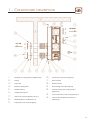
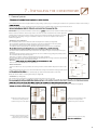
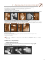
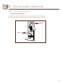
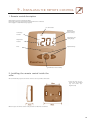
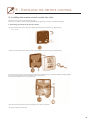
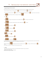
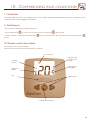
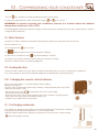
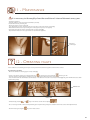
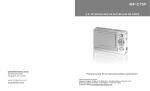
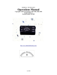
Operating and installation instructions - INOA cellar conditioners
March 2009
1
CONTENTS
WELCOME TO THE WORLD OF EUROCAVE
p.4
1 • CONDITIONER DESCRIPTION
p.5
2 • IMPORTANT SAFETY RECOMMENDATIONS
p.6
3 • ELECTRICAL POWER SUPPLY
p.6
4 • CARE FOR THE ENVIRONMENT AND ENERGY SAVING
p.6
5 • TECHNICAL SPECIFICATIONS
p.7
6 • CELLAR INSULATION
p.8
7 • INSTALLING YOUR CONDITIONER
p.9
I- General points
p.9
II- Drilling the wall
p.10
III- Fitting
p.10
Venting plate and wall mounting bracket dimensions
p.11
IV- Discharging condensate
p.13
8 • CONDITIONER OPERATION
p.14
9 • INSTALLING THE REMOTE CONTROL
p.15
I- Remote control description
p.15
II- Installing the remote control inside the cellar
p.15
III- Installing the remote control outside the cellar
p.16
10 • COMMISSIONING YOUR CONDITIONER
p.18
I- Connection
p.18
II- Switching on
p.18
III- Remote control description
p.18
IV- Installing the remote control
p.19
V- Setting the temperature
p.19
VI- Silent function
p.20
VII- “Heating” function
p.20
VIII- Changing the remote control batteries
p.20
IX- Discharging condensate
p.20
11 • MAINTENANCE
p.21
12 • OPERATING FAULTS
p.21
2
Solutions to meet all your needs
W IN E C ABIN ET S
O rigine
C lassic
Leather
Meuble à Vins
C ompact
Sommelier
Elite
STO RAGE SYST EMS
Modulothèque
Modulocube
SYST EM TO
SERVE W IN ES BY T HE GLASS
* Product not available in certain countries.
C ELLAR C O N DIT IO N ERS
Modulorack
Inoa*
Vin au Verre*
3
WELCOME TO THE WORLD
OF
EUROC AVE
O ur greatest wish is to accompany your enthusiasm for wine throughout the years…
To do so, EuroC ave puts all of its know-how into action to bring together the essential factors in optimal wine maturing:
Temperature:
T he two worst enemies of your wine are extreme temperatures and sudden fluctuations in temperature.
A constant temperature of 10° to 14°C (50 to 57°F) is considered to be ideal for your wine to reach its full potential.
O wing to its electronic regulation system, your EuroC ave IN OA conditioner is activated as soon as the cellar
temperature rises one degree above the programmed temperature. Furthermore, the presence of a heater built into the
air distributor protects your wine from any significant fall in temperature.
Humidity:
T his is an essential factor, enabling corks to retain their sealing qualities. T he level of humidity must be higher than 50%
(ideally between 60 and 75 %).
By maintaining a constant evaporation temperature, above 0°C , your EuroC ave IN OA conditioner ensures minimal drying
out of the air of your cellar and an ideal level of humidity.
Protection from light:
Light, and more especially its ultra-violet component, will rapidly prove noxious to your wine by irreversible oxidation of
its tannins. For this reason we strongly advise that wines be stored in the dark, far from U.V. light.
Protection from vibration:
Vibration disturbs the slow process of your wine’s biochemical evolution, and is often fatal for the finest wines.
T he housing of your EuroC ave conditioner is fully sound-proofed (by 20 mm polyethylene foam) and the compressor and
fans are fitted with silent blocks to absorb any residual vibration.
Natural aeration:
A constant supply of air from the outside is also indispensable.
All of these specific features can be found in the EuroC ave IN OA conditioner you have bought. W e thank you for the
confidence you have placed in us.
Usual wine serving temperatures
French wines
Alsace
Beaujolais
Bordeaux Sweet W hite
Bordeaux Dry W hite
Bordeaux Red
Bourgogne W hite
Burgundy Red
C hampagne
Jura
Languedoc-Roussillon
Provence Rosé
Savoie
Vins de Loire Dry W hite
Vins de Loire Sweet
Vins de Loire Red
Vins du Rhône
Vins du Sud O uest Sweet
Vins du Sud O uest Red
10°C
13°C
6°C
8°C
17°C
11°C
18°C
6°C
10°C
13°C
12°C
9°C
10°C
7°C
14°C
15°C
7°C
15°C
Australian wines
C abernet franc
C abernet sauvignon
C hardonnay
Merlot
Muscat à petit grain
Pinot noir
Sauvignon W hite
Semillon
Shiraz
Verdhelo
16°C
17°C
10°C
17°C
6°C
15°C
8°C
8°C
18°C
7°C
Other wines
C alifor nia
C hile
Spain
Italy
16° C
15° C
17° C
16° C
4
1 - CONDITIONER
DESCRIPTION
COLD AIR
HOT AIR
1
2
3
4
5
6
7
8
9
-
Conditioner / ceiling distance: 200 mm min.
Ceiling
Cellar wall
Metal mounting frame
Flexible ducting
Aesthetic front panel
Grid, to be cleaned regularly (see p.11)
Mounting frame / conditioner seal
10
11
12
13
14
-
15 16 -
Condenser, to be cleaned regularly
Inside of cellar
Remote control
Grid securing screws (quantity: 24)
Aesthetic front panel securing screws
(quantity: 4)
Screws to fix frame to the wall (quantity: 4)
Screws to fix conditioner to the frame
(quantity: 4)
Evaporator, to be cleaned regularly
5
2 - IMPORTANT
SAFETY RECOMMENDATIONS
Warning
W hen using your conditioner, you
should always obser ve certain
basic precautions, especially:
N ever use your conditioner for anything other than its specific purpose as described in this guide.
N ever unplug the conditioner by pulling on the supply lead. Take a firm hold on the plug and pull out smoothly in a
straight line from the wall socket.
If the power lead is damaged, it must be replaced by a qualified electrician.
Do not allow children to climb, sit, stand on or hang from the conditioner.T hey could damage the conditioner, as well
as badly hurting themselves.
Never damage your appliance’s refrigeration unit.
3 - ELECTRICAL
POWER SUPPLY
For your personal safety, the conditioner must be correctly earthed.
Your conditioner’s power lead is supplied without a plug. Installation of a power plug or connection of the conditioner to a junction box must be carried
out by a qualified electrician.
In all cases, the connection of your conditioner must be carried out on an earthed socket to prevent any risk of electric shock.
Have an electrician carry out the installation. He will tell you whether or not the socket is correctly earthed and, if necessary, will perform any work required
to bring your installation in line with standards.
IMPORTANT: any electrical work must be carried out by a qualified electrician.
Electric connection must be carried out by means of a device to ensure isolation from the mains system.T he isolating device should open all of the contacts
of all the poles ensuring complete disconnection in line with the conditions in over-voltage category III. Installation must be carried out in compliance with
national installation regulations.
Should you move to another country, check that the conditioner’s electrical rating (see grey identification label) complies with the country (voltage,
frequency).
Ensure that the plug (230 V – 13 A*) is correctly earthed and that your installation
is protected by a differential circuit breaker (30 mA*).
*not valid for some countries
4-
CARE FOR THE ENVIRONMENT
AND ENERGY SAVING
Disposal of packaging:
T he packaging used by EuroC ave is made of recyclable materials.
After unpacking your conditioner, take the packaging to a waste disposal centre. For the most part it will be recycled.
Recycling: A caring gesture
Electrical and electronic equipment have potentially hazardous effects on the environment and public health due to the presence of
noxious substances.
You should therefore never dispose of electrical or electronic equipment with unsorted municipal waste.
W hen buying a new EuroC ave product (wine cabinet, cellar conditioner, Vin au Verre), you can take advice about the recycling of your old appliance from
your EuroC ave dealer.
In compliance with legal provisions covering respect and care for the environment, your conditioner does not contain C FC s.
Energy saving:
- Install your conditioner in an appropriate place and within the recommended temperature ranges.
- Keep the door open for as short a time as possible.
N .B.: C are for the environment: when replacing your conditioner, consult your local municipal refuse department in order to observe the appropriate
recycling procedure.
For refrigerant gases, substances and some parts contained in the conditioner, EuroC ave uses recyclable materials which require a special packaging disposal
procedure to be followed.
Place unusable appliances out of use by unplugging them.
6
5 - T ECHNICAL SPECIFICATIONS
INOA CELLAR CONDITIONER
F UNCTION
The purpose of the cellar conditioner is to climate control any kind of fully
insulated room creating an ideal wine cellar environment by monitoring and
adjusting the temperature and humidity.
T EC HNOLO GY
The conditioner’s housing is dampened against sound and the compressor
and fans are fitted with silent blocks to absorb any residual vibration.
A quiet conditioner: the system automatically adjusts speeds to ambient
temperature conditions, combined with the use of particularly quiet fans,
allows the conditioner to operate very discreetly.
Energy efficiency: Inoa conditioners use the compressor infrequently,
insulation between the condenser and the evaporator minimises any
exchange between the cold and hot sections of the appliance, thus favouring
energy efficiency.
The Inoa come as standard with the hot air discharge opposite the cold air
exit. It can be ordered with the hot air exit on the left or the right side as an
option.
S P ECI F ICATIONS
I NOA 25
I NOA 50
EuroCave Inoa 25 Cellar conditioner
Dimension W385 x D322 x H1250 mm
Weight: 43 KG
Power supply 230V / 50 Hz
Volume up to 25 m3 (*)
Cooling Capacity 600W
Electrical Power 500W (**)
Heater element 650W
Cooling Gas: R134a
External Temp -5°C to 35°C
Noise level: 44dbA – 50dbA
Supplied with a 3.50 m power lead without plug
Ref: INOA 25
EuroCave Inoa 50 Cellar conditioner
Dimension W385 x D322 x H1250 mm
Weight: 46 KG
Power supply 230V / 50 Hz
Volume up to 50 m3 (*)
Cooling Capacity 1200W
Electrical Power 800W (**)
Heater element 650W
Cooling Gas: R134a
External Temp -5°C to 35°C
Noise level: 44dbA – 50dbA
Supplied with a 3.50 m power lead without plug
Ref: INOA 50
* for an isolated wine cellar following our advice please refer to our insulation guide
** for an internal temperature of 12°C and an external temperature of 32°C
Important information
For insulation, installing, positioning and more please make sure you have read our Installation
guide and our Insulation guide.
7
2 - TECHNICAL
Inoa 25
Inoa 50
Dimensions
in mm
W385 x D322
x H1250
W385 x D322
x H1250
Power
supply
230 V
/ 50 Hz
230 V
/ 50 Hz
Sample
volume m3
up to
25 m 3 *
up to
50 m 3 *
SPECIFICATIONS
Cooling
capacity W
600 W**
Weight
Kg
43 Kg
Electrical
power W
550 W**
Heating
resistance W
650 W
1200 W**
46 Kg
800 W**
650 W
Refrigerant
R134a
(without CFCs)
R134a
(without CFCs)
External
temperatures
-5°C to 35°C
-5°C to 35°C
* in a very well insulated room - ** for an internal temperature of 12° C and an external temperature of 32° C.
Supplied with a 3.50 m power lead without plug.
3 - CELLAR
INSULATION
Traditional building materials such as stone, concrete and brick are very poor insulators and only underground sections represen
t any real insulation.
It is therefore essential, in the majority of cases, to insulate the entire room to be conditioned.
Insulate – yes but how?
We recommend that you use extruded polystyrene, currently the most efficient product on the market. It is the least flammable and
the most durable
material. It also has the advantage of not being attacked by rodents. Furthermore, extruded polystyrene boards can be layered and
therefore prevent thermal
bridges.To increase your conditioner’s lifespan and reduce electricity consumption, we recommend that you use extruded polystyre
ne which is at least 80
mm thick.
80 mm of extruded polystyrene provides the same amount of insulation as a 5m thick stone wall.
The insulation must be completely continuous (no gaps).
Insulation boards: different methods of fitting are possible
How can you determine whether or not a material is a good insulator? The insulation performance of a material is established ybits R thermal resistance
(m2.°C/W). It determines the material’s ability to conduct heat.
R = e/ λ - The greater the R coefficient, the better the insulation. (λ = thermal conductivity coefficient)
There are 3 types of insulation boards:
Insulator only, complex (with plaster cover) or sandwich (plaster both sides)
Depending on the type of insulator chosen, several methods of fitting are possible:
• Against the walls
- Standard extruded polystyrene board: pre-cut to the dimensions of the area to be conditioned, they are fitted using high-bondortar.
m For a more acceptable
finish, it is possible to fix rails onto which you screw the plaster board panels over the polystyrene.
- Sandwich or complex boards: the polystyrene is already integrated into the plaster board.
Whatever the method used, all kinds of decorative finishes are possible to obtain an attractive wall.
If you only want to condition a section of your room, install a plaster board dividing wall then insulate the side of the roomot be conditioned.
N.B.: Before being insulated, walls must be clean. If they are too damp, clean them with a wire brush then clean with a high pressu
re water jet and paint with
an emulsion paint.
• On the ceiling and door
The process for insulating the ceiling and door is identical to that of the walls.We recommend that you use extruded polystyren
e.
• On the floor (insulation optional)
- Original clay floor: not insulating favours the passage of humidity, which is good for the wine.
- Concrete floor (for example): Concrete is a very poor insulator. A few centimetres of fine gravel can, in some cases, improve insulation.
It is essential that the surface material used for the floor (whether or not covering
insulation) can support the weight of wine racks and has resistance to compression.
Tools required
- handsaw, tape measure, bricklayer’s ruler, trestles, screwdriver or screw gun, drill, hammer, level, plumb line, wood mallet, spatula,
recision
p
knife...
8
7 - INSTALLING THE
CONDITIONER
I - General points
- Never damage the appliance’s refrigerating circuit.
Your conditioner’s power lead is supplied without a plug. “Fitting a power plug or connecting the conditioner to a junction box must be carried out by a
In all cases, connection of your conditioner must be carried out on an earthed socket to prevent any risk of electric shock.
*not valid for some countries
IMPORTANT : any electrical work must be carried out by a
electrician. Power outlet not valid for some countries.
Electric connection must be carried out by means of a device to ensure isolation from the mains system. The
isolating device should open all of the contacts of all the poles ensuring complete disconnection in line with
the conditions in over-voltage category III. Installation must ber ca ried out in compliance with national
installation regulations.
• Positioning your conditioner:
The conditioner produces cold air inside the cellar and expels hot air outside (see diagram A).
- Do not install the conditioner facing the door of the room (risk of condensation on the door joints).
- Do not place the external section of the conditioner above a source of heat.
- For insulation reasons, there must be no windows or bay windows in the room to be conditioned.
- Is it not better to state that pipes with hot water must be insulated so that there is no heat loss?
- The exterior of the conditioner must not be located in an area subject to ingress of rain, wind, snow or poor
quality air.
- No heat-producing appliance must be located in the area to be conditioned (e.g. refrigerator, radiator, boiler).
- Do not obstruct the air entry and exit points.
- Never place a container or object containing liquid on top of the conditioner.
- The room where the hot air is expelled must, ideally, be approximately twice as large as the wine cellar and well
ventilated so that the hot air can be properly expelled.
- Wait 48 h
- Never connect several conditioners to a multi-socket.
Ventilated
room
CELLAR
Temperature:
Max.: 35°C
Min.: -5°C
Diagram A
Bottles
CELLAR
Door
Conditioner
CELLAR
• Recommendations:
Bottles
- Fit your conditioner as close as possible to the ceiling in order to ensure uniform dispersal of cold air in the
cellar.
- We recommend that you leave a space of 200 mm between the ceiling and conditioner housing to make it easier
Door
- Air outlets (hot and cold) must not be obstructed by any obstacles (minimum distance: 1500 mm).
Direct the cold air outlet so it is facing the bottles (see diagram D).
CELLAR
Diagram D
• Installation: (see B diagrams)
The conditioner was designed to be completely modular and adapt to any type of cellar.
Conditioner
Conditioner
Bottles
Door
however, installing it at a height for improved air convection).
You also have the option of expelling hot air outside the room by way of extractor piping (standard piping, 160 mm in diameter, not supplied).
Cold air
discharged
Cold air
discharged
Hot air
expelled
Hot air
expelled
Conditioner housed inside the cellar
with extraction facing forwards /
aesthetic front panel on the outside
Diagram B
Diagram B
Conditioner housed outside the cellar
with extraction on the left side /
aesthetic front panel on the inside.
Diagram B
Diagram B
Conditioner housed outside the cellar
with extraction facing forwards /
aesthetic front panel on the inside
Conditioner housed inside the cellar,
4
GB
9
7 - INSTALLING THE
CONDITIONER
• Fitting: (see C diagrams)
The conditioner comes supplied with a metallic mounting frame which
simplifies the process of drilling air entry and exit holes.
It also has extendable ducting to be cut to length (75 cm each) in order to
install the conditioner whatever the thickness of the wall.
Finally, the conditioner is supplied with an aesthetic front panel and 4 grids
for an aesthetic appearance.
Extendable
ducting
Grid
Extendable
ducting
Aesthetic
front panel
Wall drill
holes
Metallic
mounting
frame
Metallic
mounting
frame
Grid
Aesthetic
front panel
Conditioner housed outside the cellar
Diagram C
Wall drill
holes
Conditioner housed inside the cellar
Diagram C
II- Drilling the wall
- Determine the location of the conditioner housing (inside or outside the cellar)
- Position the metallic mounting frame:(1)
• in relation to the ceiling if fitting the conditioner at a height (maintain a distance of 200
mm between the top of the frame and the ceiling),
• in relation to the floor for a low fitting (maintain a distance of 80 mm between the
bottom of the frame and the floor).
- Use the metallic frame to outline the position of the 2 drill holes (2).
- Drill the wall.The holes must be larger than the outline drawn – between 210 mm min. and
280 mm max.
(1)
(2)
III- Fitting
- Fold the ring’s 4 supports inwards (1).
- Fit the 2 extendable ducts onto the rings of the metallic frame(2).
- Screw the securing rings onto the ducts (3).
- Position the metallic frame while passing the flexible ducts through the 2 holes drilled into the wall
(4).
- Push back the 4 supports towards the outside of the ring(5).
(1)
(2)
(3)
(4)
(5)
- Screw the metallic frame onto the wall with 2 high screws and two low screws (not supplied).Use screws suitable for the wallmaterial (6).
- We recommend that you put a bead of silicone between the plate and the wall to ensure effective sealing.
- Pull the 2 ducts (fixed to the metallic frame) through the other side of the wall (7).
- Stretch the ducts to the maximum in order to make them as smooth as possible(8).
- Cut the ducts flush with the wall using a Stanley knife for the material(9) and pliers for the metallic wiring(10).
(6)
(7)
(8)
(9)
(10)
10
Wall mounting bracket dimensions
Cold side
Hot side
Inoa located outside the cellar
Inoa located inside the cellar
AFTER SALES DEPARTMENT
TECHNICAL NOTE N° 031
Date : 15/11/10
Revision : 0
Page : 1 of 2
Subject: INOA-TECHNICAL DATAS AND TUBING
UNITS AFFECTED:
INOA25 et INOA50
SERIAL NUMBER:
All
DATE OF PRODUCTION:
Since June 2007
Position of the panels :
Cold air out
Warm air side
Cold air side
Cellar air in
Cold air outlet front side
Maximum pipe lengths recommended:
Two parts, 7 linear meters of pipe diameter 160 mm without elbow.
Or
Two parts, 5 linear meters of pipe diameter 160 mm with 3 90°‛s elbows.
You can only duct the warm air side.
Do not duct cold air.
AFTER SALES DEPARTMENT
TECHNICAL NOTE N° 031
Date : 15/11/10
Revision : 0
Page : 1 of 2
Subject: INOA-TECHNICAL DATAS AND TUBING
Extraction kit: AEVACLM or PEVACLM (not supplied with the air conditioner, option
to be ordered), one kit per hole.
Technical datas: INOA 230 V 50 Hz
Maximum volume of the wine cellar
Cooling power
Maximum distance for the remote control
Quantity of speeds for the condenser fan
Quantity of speeds of the evaporator fan
Condenser fan air flow (per speed : 1, 2, 3, 4) in m3/h
Evaporator fan air flow (per speed : 1, 2, 3) in m3/h
Gas load in R134a
Pressures BP and HP for 35°c (in bar)
Type of gas reducer
Condenser gas temperature
INOA25
25 m3
600 W
10 m
4
3
230, 335,
431, 563
199, 285,
382
400 grs
2,3 ; 11,2
Capillary
47°c
INOA50
50 m3
1200 W
10 m
4
3
273, 353,
473, 682
227, 352,
445
400 grs
2,1 ; 10,5
Capillary
45°c
7 - INSTALLING THE
CONDITIONER
- Position and fit the aesthetic front panel to the wall (screws not supplied). Use screws suitable for the wall material(11).
- We recommend that you put a bead of silicone between the panel and the wall to ensure effective sealing.
- Fold the flange’s 4 supports inwards (12).
- Place the ducts onto the flanges ensuring that they are well secured on the supports(13).
- Push the 4 supports towards the outside of the flange(14).
- On the side of the conditioner to be placed against the wall unscrew the 2 grids from the housing using the supplied Hex wren
ch and retain the screws.) (15).
(11)
(12)
(13)
(14)
(15)
- Using the screws retained in the last instruction, screw the 2 grids onto the aesthetic front panel(16).
- Unscrew the 2 screws on the top of the conditioner using a Hex wrench (supplied), on the side to be placed against the wall. Re
tain the two screws (17).
- Fix the conditioner housing to the metallic frame, taking care to press firmly onto the foam(18).
- Screw down the conditioner housing using 2 screws at the top (those retained earlier) and 2 screws at the bottom (supplied inthe accessories packet) (19).
(16)
(17)
(18)
(19)
• Fitting onto a door:
You can fit the conditioner onto a door.
In this case, it is ESSENTIAL to check that the door is capable of supporting a weight of 46 kg and that it does not produce vibration.
The procedure for fitting is the same as for the wall.
• Fitting close to the floor:
When the conditioner is fitted close to the floor it is ESSENTIAL that it is fixed to
the wall.
• Conditioner with air extraction via piping:
Repeat the steps described at the beginning of paragraph III.
Conditioner housed outside the cellar:
- On the conditioner housing, unscrew the 2 grids (openings that will not be placed against the wall) using a Hex wrench (suppli
ed).
- Where the grids were located, position and screw, using a Hex wrench (supplied) the 2 flanges* onto the housing(1) and (2).
- Fit together the reducer* (3).
- Position the air extraction piping (standard piping, 160 mm in diameter, not supplied).
(1)
(2)
(3)
*Consult your EuroCave distributor
12
7 - INSTALLING THE
CONDITIONER
Conditioner housed inside the cellar:
There are 2 methods for attaching the hot air extraction piping:
- Attaching the piping directly to the aesthetic front panel:
- Position and screw, using a Hex wrench (supplied), the two supplied flanges* onto the aesthetic front panel
(1).
- Fit together the reducer (2).
- Position the air extraction piping (standard piping, 160 mm in diameter, not supplied)
(3).
(1)
(2)
(3)
- Attaching the piping directly to the conditioner housing (the extraction piping passes through the wall):
If using this method, you must not use the flexible ducting supplied with the
conditioner.
- Fit the reducer* directly onto the mounting frame through the wall(1).
- Position the air extraction piping (standard piping, 160 mm in diameter, not supplied)
(2) (3).
(1)
(2)
(3)
For this type of fitting, it is necessary to ensure sealing around the piping.
*Consult your EuroCave distributor
IV- Discharging condensate
The conditioner was designed to allow condensate to be discharged (discharge pipe located under the
conditioner’s housing) either inside the cellar, if the humidity level is too low, or outside the cellar.
Simply pass the pipes through the wall to discharge the condensate into the room next to the conditioner
housing.
Ensure that the piping is not cramped.
13
8 - CONDITIONER
OPERATION
T he IN OA conditioner is fitted with a refrigerating unit:
• an evaporator forces cold air inside the room,
• a condenser expels the hot air outside.
The evaporator fan operates continuously to ensure that air is constantly mixed and that temperatures
are as uniform as possible,in accordance with speeds automatically adjusted according to requirements.
Fan
Cold air
Hot air
(heated if necessary)
Heater
Evaporator
Hot air
Turbine
Condenser
Compressor
14
9 - INSTALLING THE
REMOTE CONTROL
I- Remote control description
Radio frequency remote control (433.92 Mhz)
Each remote control has a personalised code matched to the conditioner.
Power supply: 2 x 3V (CR 2430 battery, supplied)
On / off indicator
Temperature
units (according
to the country)
Low battery
indicator
Temperature and
setting display
Temperature
indicator
Adjustment keys
Knob
Confirmation and on/off key
II- Installing the remote control inside the
cellar
We recommend that you place the remote control as close as possible to the bottles.
Fit the unit close to your
bottles using the supplied
pegs and screws (see
diagram below)
NB: Do not place the remote control in the path of the conditioner’s cold air flow.
15
9 - INSTALLING THE
REMOTE CONTROL
III- Installing the remote control outside the cellar
The remote control can also be placed outside the cellar.
In this case, it is essential to connect a sensor (supplied with the appliance) to the remote control before installing it.
a- Connecting the sensor to the remote control
- On the back of the remote control, push the 2 batteries downwards using a screwdriver (see diagram below).
Battery CR2430
- Remove the central knob, unscrew the screw with a small screwdriver and open the unit (see diagram below)
On the back, connect the sensor’s 2 wires (blue and red) to the circuit connector using a small flat screwdriver (see diagram below).
You can connect either the blue wire or the red wire to the circuit connector.
Pass the wires through the recess on the top of the unit.
- Close the unit, ensuring that the wires pass through the recess and are not jammed
- Rescrew and replace the central knob
16
9 - INSTALLING THE
REMOTE CONTROL
- Programming the remote control
Where placing the remote control outside the cellar, having connected the external sensor, it is essential to reprogramme the uni
t
- To turn on the remote control, press and hold down the
- First press and continuously hold down the
lines
- Press
- The
- The
screen appears indicating IN (IN= internal installation). Press the
.
key to change to OUT external mode.
display appears indicating OUT (OUT= external installation). Press
- The
screen appears. Press
- The
pictogram appears. Press
- The
key for several seconds until three
.
pictogram appears. Press
- The
indicator goes off.
key, at the same time press and continuously hold down the
appear.The model number is then displayed and flashes.
- The
-
key for about 8 seconds until the
.appears. Press
to confirm.
.
.
.
.
pictogram appears. Press
screen appears, then
.
.
If you wish to reprogramme the remote control for an internal sensor, disconnect the wired sensor and reprogramme the remote control in internal mode
(IN) by repeating the first two steps described in the paragraph above (see 5-III-b p.11):
The 2nd screen displays
confirm.
indicating OUT (OUT= external installation). Press the
key to change to IN internal mode. Press
to
Then repeat the same steps, as indicated in the above paragraph (see 5-III-b).
c- Fitting
- Fit the remote control and sensor using the screws and pegs supplied (see diagram on page 9, chapter II).
- Place the sensor inside the cellar.
- Place the sensor as close as possible to the bottles
N.B.: the sensor has a range of 3 metres.
17
10 - COMMISSIONING YOUR CONDITIONER
I- C onnection
C heck that the plug is connected to a power supply (presence of correct amp fuses, functioning 30 mA* differential circuit breaker - not applicable to certain
countries).W ait 48 hours before plugging in your conditioner.
II- Switching on
- Place the switch, located under the conditioner, in position 1.
- Press and hold down the
key on your remote control for about 8 seconds, until the
To put your conditioner on standby, press and hold down the
goes off.
indicator goes off.
key on your remote control for about 5 seconds and release it before the indicator
III- Remote control description
Radio frequency remote control (433.92 Mhz).
Each remote control has a personalised code matched to the conditioner.
O n / off indicator
Temperature units
(according to the
country)
Low battery
indicator
Temperature and
setting display
Temperature
indicator
K nob
Adjustment keys
C onfirmation and on/off key
18
10 - COMMISSIONING YOUR CONDITIONER
IV- Installing the remote control
You can install the remote control inside your cellar.
W e recommend that you place it as close as possible to the bottles.
Fix the unit close to your bottles using the supplied pegs and screws (see diagram below)
N .B.: Do not place the remote control in the path of the conditioner’s cold air flow.
It is also possible to place the remote control outside the cellar.
In this case, an external sensor (supplied) must be connected to the remote control and then the remote control must be reprogrammed.
For further details, contact your EuroC ave retailer.
V- Setting the temperature
Setting the temperature of your conditioner is carried out entirely from the remote control which has the following layout:
C ellar
temperature
display
Temperature
units (according
to the country)
- Temperature display: displays the actual temperature inside
your cellar.
- Setting keys: allow you to select the desired temperature
inside the cellar.
Temperature
indicator
C ellar temperature
setting keys
Selection and confirmation key
To adjust the temperature:
- Press then immediately release the
key.
T he setting then appears (the temperature flashes).
- - W hen the temperature flashes, you have 7 seconds to change the setting by pressing the
the previous setting.
or
keys, otherwise the display automatically returns to
T he recommended setting range for maturing wine: 10 to 14°C .
19
10 - COMMISSIONING YOUR CONDITIONER
- Press the
key to confirm the new setting, the display then returns to the new setting.
T he setting can be adjusted between 9 and 15°C . Beyond this range, the
and
keys do not work.
WARNING: to operate correctly, your conditioner must be in a location where the ambient
temperature is between -5°C is 35°C.
W hen making significant modifications to temperature settings, it can take several hours for the temperature in your cellar to stabilise and for the conditioner
to display the desired temperature.
VI- Silent function
Your EuroC ave conditioner is fitted with a silent function which allows the sound level to be reduced when you enter the cellar.
W hen the conditioner is on:
- Press and hold down the
T he
key for 3 seconds.
display then appears. N ext the current temperature is displayed.
You will be able to see this function via the
pictogram which flashes for 15 minutes.
T he compressor then remains in operation and the fans change to slow speed for 15 minutes.
After this, the conditioner returns to the default operating speed.
VII- Heating function
T he EuroC ave IN OA conditioner has a heater (650 W ) allowing the internal temperature in your cellar to be maintained at an optimal level.
As soon as the temperature drops below the programmed temperature, the heating function is automatically activated.
VIII- C hanging the remote control batteries
Remote control power supply: 1 x 3 V (C R 2430 battery) (2 batteries supplied)
Battery life: 2 years approx
T he remote control is supplied with 2 batteries. O nly one battery is required (pull off the plastic strip to make it
useable).T he other battery is a spare.
- W hen the battery runs out, the
pictogram flashes on the remote control’s display.
- Take the remote control off the wall.
- O n the back of the remote control, push the used battery down using a screwdriver (see diagram opposite).
- Pull the strip from the spare battery, which will then be ready for use.
- Remember to buy a replacement for the spare battery.
IX - Discharging condensate
Your conditioner was designed to allow condensate to be discharged (discharge pipe located under the conditioner’s
housing) either inside the cellar, if the humidity level is too low, or outside the cellar.
Simply pass the pipe through the wall to discharge the condensate into the room next to the conditioner housing.
Ensure that the piping is not kinked.
20
11 - MAINTENANCE
It is necessary to thoroughly clean the conditioner’s internal elements every year.
- Unplug the appliance.
- Place the appliance on the ground to disassemble it (4 screws).
- Vacuum the 4 air entry and exit grids.
- Remove the upper cover (2 screws) (1).
- Snap off from the top the 2 columns in order to access the 8 screws of the 2 front sections (2).
- Disassemble the front sections by removing the screws (square end pieces, not supplied).
- Thoroughly clean the ribs of the 2 exchangers with a vacuum cleaner(3).
- Repeat these instructions in the opposite order to reassemble the appliance.
Ribs of the
2 exchangers
(1)
(2)
12 - OPERATING
(3)
FAULTS
If the conditioner is not working, there may be loss of synchronism between the appliance and the remote control.
Synchronising procedure:
- Remove the conditioner housing upper cover (4 screws) (1).
- To turn on the remote control, press and hold down the
key for about 8 seconds, until the
indicator goes off.
- Place the switch, located under the conditioner, in position 1.The green LED on the board comes on(2).
- Press and hold down the On/Off button (brown button) on the board for more than 6 seconds, then release (3). The green LED will then start to flash
(synchronising mode).
On/ off button
(1)
(2)
(3)
Green LED
- Simultaneously press the
and
keys on the remote control until ! is displayed
.
- As soon as the green LED on the board stops flashing (end of synchronising mode), the conditioner and remote control are thensynchronised.
- Exit "RF" mode by pressing the
key on the remote control.
21
WARNING
The information in this document is subject to modification without prior notice.
EuroCave offers no guarantee on this equipment item if it is used for any specific purpose other than that for which it was des
igned. EuroCave cannot be
held responsible for any errors in this manual, nor for any damage linked to or following the provision, performance or use of the equipment item.
All photocopying, reproduction, translation, wether partial or total, are strictly prohibited, without prior written consent from Eu
roCave.
12
GB
22
EuroCave UK
57 Chiltern Street
London W1U 6ND
020 7935 4679
[email protected]
www.eurocave.co.uk - [email protected]
23