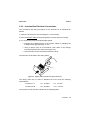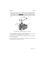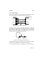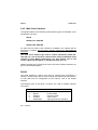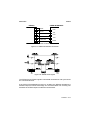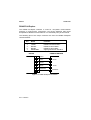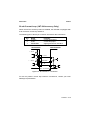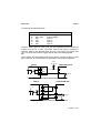
1
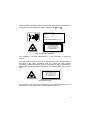
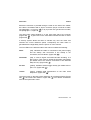
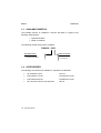
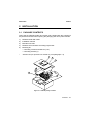
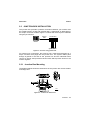
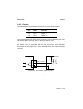
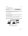
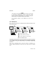
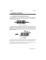
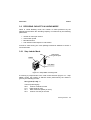
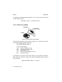
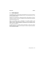
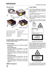
DS4300 INSTALLATION MANUAL We DATALOGIC S.p.A. Via Candini, 2 40012 - Lippo di Calderara Bologna - Italy declare under our sole responsibility that the product DS4300-XXXX, Laser Scanner and all its models to which this declaration relates is in conformity with the following standards or other normative documents EN 55022, August 1994: LIMITS AND METHODS OF MEASUREMENTS OF RADIO DISTURBANCE CHARACTERISTICS OF INFORMATION TECHNOLOGY EQUIPMENT (ITE) EN 50082-2, March 1995: ELECTROMAGNETIC COMPATIBILITY. GENERIC IMMUNITY STANDARD. PART 2: INDUSTRIAL ENVIRONMENT Following the provision of the Directive(s): 89/336 CEE AND SUCCESSIVE AMENDMENTS, 92/31 CEE; 93/68 CEE Ruggero Cacioppo Lippo di Calderara, 16.11.1998 Quality Assurance Supervisor Product names mentioned herein are for identification purposes only and may be trademarks and or registered trademarks of their respective companies. Datalogic S.p.A. reserves the right to make modifications and improvements without prior notification. - 1999 Datalogic S.p.A. 821000261 (Rev. A) CONTENTS GUIDE TO INSTALLATION ...............................................................v General View ..................................................................................... vi SAFETY PRECAUTIONS ................................................................viii Laser Safety......................................................................................viii Standard Regulations .......................................................................viii 1 1.1 1.2 1.3 1.4 GENERAL FEATURES ...................................................................1.1 Introduction ......................................................................................1.1 Description.......................................................................................1.2 Available Models..............................................................................1.4 Accessories .....................................................................................1.4 2 2.1 2.2 2.3 2.3.1 2.3.2 2.4 2.4.1 2.4.2 INSTALLATION ..............................................................................2.1 Package Contents ...........................................................................2.1 Mechanical Installation ....................................................................2.2 Junction Box Installation ..................................................................2.3 Junction Box Mounting ....................................................................2.3 Junction Box Electrical Connections................................................2.5 Electrical Connections for 25-pin Models ........................................2.8 Power Supply...................................................................................2.9 Main Serial Interface......................................................................2.10 RS232 ...........................................................................................2.10 RS485 Full-Duplex ........................................................................2.12 RS485 Half-Duplex ........................................................................2.13 20 mA Current Loop (INT-24 Accessory Only) .............................2.15 Auxiliary RS232 Interface ..............................................................2.16 Inputs .............................................................................................2.16 Outputs ..........................................................................................2.19 Positioning .....................................................................................2.20 Typical Layouts ..............................................................................2.21 Point-to-Point .................................................................................2.21 Pass Through ................................................................................2.22 RS232 Master/Slave......................................................................2.23 RS485 Master/Slave......................................................................2.24 Multiplexer .....................................................................................2.25 2.4.3 2.4.4 2.4.5 2.5 2.6 2.6.1 2.6.2 2.6.3 2.6.4 2.6.5 iii 3 3.1 3.1.1 3.2 3.2.1 3.2.2 3.3 3.4 READING FEATURES ....................................................................3.1 Advanced Code Reconstruction ......................................................3.1 Tilt Angle for Advanced Code Reconstruction.................................3.2 Decoding Capacity in Linear Mode ..................................................3.3 Step Ladder Mode ...........................................................................3.3 Picket Fence Mode ..........................................................................3.4 Performance ....................................................................................3.5 Reading Diagrams ...........................................................................3.6 4 4.1 MAINTENANCE ..............................................................................4.1 Cleaning...........................................................................................4.1 5 TECHNICAL FEATURES................................................................5.1 iv GUIDE TO INSTALLATION The following can be used as a checklist to verify all of the steps necessary for complete installation of the DS4300 scanner. 1) Read all information in the section "Safety Precautions" at the beginning of this manual. 2) Correctly position and mount the scanner for barcode reading according to the information in paragraphs 2.2, 2.5 and 3.4. 3) Provide correct system cabling according to the signals necessary for your application (see the applicable sub-paragraphs under 2.3 or 2.4). 4) Install the Configuration Disk. Upon successful completion of the installation, the readme.hlp file is opened, giving details about how to get started configuring your scanner. See also the Guide to Rapid Configuration link. Specific parameter details are available in the Help On Line. NOTE Fine tuning of the scanner position for barcode reading can be accomplished using the Test Mode as described in WinHost. The installation is now complete. v DS4300 General View 11 10 9 8 6 4 2 1 5 7 3 Figure A 1 Cable with 25-pin connector 7 Warning and Classification labels 2 Mounting holes Ready LED 8 9 Laser active LED 5 Good Read LED External Trigger LED 10 Laser beam output window 11 Accessory mounting holes 6 Data TX LED 3 4 vi Warning Label DS4300 General View 11 10 9 8 6 2 5 4 7 3 1 Figure B 1 Cable with junction box 7 Warning and Classification labels 2 Mounting holes 8 9 Warning Label Laser active LED 3 Ready LED 4 Good Read LED 5 External Trigger LED 6 10 Laser beam output window 11 Accessory mounting holes Data TX LED vii SAFETY PRECAUTIONS LASER SAFETY The following information is provided to comply with the rules imposed by international authorities and refers to the correct use of the DS4300 scanner. Standard Regulations This scanner utilizes a low-power laser diode. Although staring directly at the laser beam momentarily causes no known biological damage, avoid staring at the beam as one would with any very strong light source, such as the sun. Avoid that the laser beam hits the eye of an observer, even through reflective surfaces such as mirrors, etc. This product conforms to the applicable requirements of both IEC 825-1 and CDRH 21 CFR 1040 at the date of manufacture. The scanner is classified as a Class 2 laser product according to IEC 825-1 regulations and as a Class II laser product according to CDRH regulations. There is a safety device which allows the laser to be switched on only if the motor is rotating above the threshold for its correct scanning speed. The laser beam can be switched off through a software command (see also “Beam Shutter” in the WinHost Help On Line). WARNING Use of controls or adjustments or performance of procedures other than those specified herein may result in exposure to hazardous visible laser light. The laser light is visible to the human eye and is emitted from the window on the front of the scanner (Figure A/B, 10 ). viii Warning labels indicating exposure to laser light and the device classification are applied onto the body of the scanner (Figure A/B, 8 and 7 ). DATALOGIC S.p.A. Via Candini, 2 40012 LIPPO DI CALDERARA (BO) ITALY Model No. Serial No. Volt Amp. Manufactured This product conforms to the applicable requirements of 21CFR1040 at the date of manufacture. LASER LIGHT DO NOT STARE INTO BEAM CLASS 2 LASER PRODUCT MAXIMUM OUTPUT RADIATION 1 mW EMITTED WAVE LENGTH 630~680 nm TO IEC 825-1 (1993) Warning and device class labels For installation, use and maintenance it is not necessary to open the scanner. The laser diode used in this device is classified as a class 3B laser product according to IEC 825-1 regulations and as a Class IIIb laser product according to CDRH regulations. As it is not possible to apply a classification label on the laser diode used in this device, the following label is reproduced here: LASER LIGHT AVOID EXPOSURE TO BEAM CLASS 3B LASER PRODUCT MAX. OUTPUT RADIATION 7 mW EMITTED WAVE LENGTH 630~680 nm TO IEC 825-1 (1993) Laser diode class label Any violation of the optic parts in particular can cause radiation up to the maximum level of the laser diode (30 mW at 630 to 680 nm). ix This page is intentionally left blank. x DATALOGIC DS4300 1 GENERAL FEATURES 1.1 INTRODUCTION The DS4300 is a compact laser scanner complete with decoder which employs Datalogic’s powerful ACR™ (Advanced Code Reconstruction) technology. It was designed to satisfy the most demanding requirements associated with omni-directional scanning, reading of non-oriented barcode labels, and reading of poorly printed or damaged labels. Standard Application Program A Standard Application Program is factory-loaded onto the DS4300. This program controls barcode reading, serial port interfacing, data formatting and many other operating and control parameters. It is completely user configurable from a host computer using the WinHost interface utility program provided on diskette with the scanner or using the Host Mode programming procedure, by ESC sequences via the serial interface. There are four different programmable operating modes to suit various barcode reading system requirements. Included in these is a test mode to verify the reading features and exact positioning of the scanner without using external tools. Programmability If your requirements are not met by the Standard Application Program, Custom Application Programs can be developed by your local Datalogic distributor. General Features - 1.1 DS4300 DATALOGIC 1.2 DESCRIPTION Some of the main features of this scanner are given below: • code reconstruction • high scanning speed (800 scans/sec) • completely configurable from host computer • 2 serial communication interfaces • reads most popular codes • supply voltage from 10 to 30 Vdc • test mode to verify the reading features and exact positioning of the scanner without the need for external tools • configurable in different operating modes to suit the most various barcode reading system requirements • code verifier • possibility to detect the position of the label in the scan line The DS4300 scanner uses a solid state laser diode as a light source; the light emitted has a wavelength between 630 and 680 nm. Refer to the section "Safety Precautions" at the beginning of this manual for information on laser safety. The reader is contained in a rugged aluminum housing; the mechanical dimensions are 101 x 83.5 x 42 mm and it weighs about 800 g. The protection class of the enclosure is IP65, therefore the reader is particularly suitable for industrial environments where high protection against harsh external conditions is required. 1.2 - General Features DATALOGIC DS4300 Electrical connection is provided through a cable on the side of the reader; this cable is terminated with a 25-pin connector (25-pin connector models, see paragraph 1.3, Figure A, 1 ) or by a junction box (junction box models, see paragraph 1.3, Figure B, 1 ). The laser beam output window is on the right hand side of the scanner (Figure A/B, 10 ). A green LED on the same side indicates the laser is active (Figure A/B, 9 ). A security system allows the laser to activate only once the motor has reached the correct rotational speed; consequently the laser beam is generated after a slight delay from the power on of the scanner. The four LEDs on the left hand side of the scanner indicate the following: READY (red), indicates the reader is connected to the power supply and the startup was successful. If the startup is not successful, this LED blinks. (Figure A/B, 3 ). GOOD READ (red), is used to signal successful barcode decoding. It is also used in Test mode to signal the decoding percentage (for details refer to the section "Test Mode" in the WinHost Help On Line). (Figure A/B, 4 ). EXT TRIG (yellow), indicates external trigger activity (for details refer to par.2.4.4. (Figure A/B, 5 ). TX DATA (green), indicates data transmission on the main serial output line. (Figure A/B, 6 ). The screw holes on the body of the reader are for mechanical fixture (Figure A/B, 2 ); the screw holes shown in Figure A/B, 11 are to attach accessories such as the optional 90° mirror. General Features - 1.3 DS4300 DATALOGIC 1.3 AVAILABLE MODELS The DS4300 scanner is available in versions that differ in regard to the following characteristics: • Optical Resolution • Cable Termination The following models are therefore available: DS4300 - 100X Optical Resolution Cable Termination 1 = Standard Resolution 0 = 25-pin connector 1 = junction box 1.4 ACCESSORIES The following accessories are available on request for the DS4300: • 90° deflection mirror GFC-41 • Power Block 110 Vac PG110/DVE-1212A • Power Block 220 Vac PG220/DVE-1212A • 20 mA Active Current Loop interface INT-24 1.4 - General Features DATALOGIC DS4300 2 INSTALLATION 2.1 PACKAGE CONTENTS Verify that the DS4300 reader and all the parts supplied with the equipment are present and intact when opening the packaging; the list of parts includes: 1) 2) 3) 4) 5) DS4300 reader with cable Installation manual Barcode test chart DS4300 communication and utility program disk Mounting kit • Mounting screws and washers (4 ea.) • Mounting bracket (1) * Junction box (for junction box models only, see paragraph 1.3) 4 3 2 5 * 1 Figure 2.1 - DS4300 package contents Installation - 2.1 DS4300 DATALOGIC 2.2 MECHANICAL INSTALLATION DS4300 can be installed to operate in different positions. The four screw holes (M4 x 5) on the body of the reader are for mechanical fixture (Figure A/B, 2 ). The diagram below gives the overall dimensions of the scanner and may be used for its installation. Refer to paragraph 2.5 for correct positioning. Figure 2.2 - Overall dimensions 2.2 - Installation DATALOGIC DS4300 2.3 JUNCTION BOX INSTALLATION The junction box provides a passive connection between your scanner and the outside world in a fast and practical way. It represents an alternative to the 25-pin connector models. Figure 2.3 shows the basic layout of DS4300 using the junction box. Scanner cable Junction Box DS4300 System cables Figure 2.3 - Scanner using junction box For junction box connections, the scanner has a cable that terminates in a 24-pin connector that plugs into the junction box. The system cables pass through 6 glands in the side of the junction box and the individual wires connect to spring clamp terminal blocks inside which provide access to all scanner signals. 2.3.1 Junction Box Mounting The diagram below shows the dimensions of the junction box and its relative mounting holes. mm in Figure 2.4 - Junction box dimensions Installation - 2.3 DS4300 DATALOGIC The junction box is designed to be mounted to a panel of metal, plastic or other appropriate material using the mounting screws provided in the package. To do this: 1) Open the junction box by unscrewing the 4 cover screws. If necessary, using the two mounting holes inside the junction box as a pattern, mark the panel with an appropriate object and then drill two small pilot holes in the panel. 2) Align the junction box and insert the two self-threading screws with their washers and screw them into the panel until tight (see Figure 2.5). Figure 2.5 - Junction box mounting 2.4 - Installation DATALOGIC DS4300 2.3.2 Junction Box Electrical Connections The connection and wiring procedure for the junction box is described as follows: 1) Open the junction box by unscrewing the 4 cover screws. 2) Pass all System cables through the glands in the junction box housing. 3) To connect the power and input/output signals: • Prepare the individual wires of the system cables by stripping the insulation back approximately 11 mm. • Using a device such as a screwdriver, push down on the orange lever directly above the clamp (see Figure 2.6). • Insert the wire into the clamp and release the lever. The wire will now be held in the spring clamp. Figure 2.6 - System cable connections to the junction box The wiring used can be solid or stranded but must meet the following specifications. Positions 1-4: 24 - 16 AWG 0.2 - 1.5 mm² Positions 5-39: 26 - 20 AWG 0.14 - 0.5 mm² The junction box pinouts are indicated in the following table: Installation - 2.5 DS4300 DATALOGIC J. BOX pinout for DS4300 Pin Name 01 02 03 04 05 06 07 08 09 10 11 12 13 14 15 16 17 18 19 20 21 22 23 *24 *25 *26 27 28 29 30 31 32 33 34 35 36 37 38 39 VS GND VS GND CHASSIS VS VS EXT TRIG+ EXT TRIGGND GND VS VS IN1+ IN1GND GND OUT1+ OUT1OUT2+ OUT2IN2+ IN2Main interface signals see table below Reserved GND Main interface signals see table below 18 J1 39 5 1 17 Figure 2.7 - Junction box connector and pinout To allow connection of an NEC Class 2 Power Unit, use a correct female plug adapter. Junction Box NEC Class 2 Power supply Female Plug System cables Figure 2.8 - NEC Class 2 Power unit connections * The signals on pins 24, 25 and 26 are repeated on pins 29, 30 and 31 to facilitate network connections (i.e. Multiplexer connections using the RS485 half-duplex Interface). In this way the network bus can enter and exit the junction box from different spring clamps but be physically connected together. GND TXAUX SGND Aux GND RXAUX Reserved Pin 24, 29 25, 30 26, 31 32 33 2.6 - Installation RS232 TX232 RTS232 SGND Main RX232 CTS232 RS485 full-duplex TX485+ TX485SGND Main RX485+ RX485- RS485 half-duplex RTX485+ RTX485SGND Main 20 mA CL (INT-24 Only) CLOUTSGND Main CLIN- DATALOGIC DS4300 4) After wiring the junction box and while the scanner is unplugged from the power supply, place the Scanner cable so that the rubber seal fits into the cutout in the housing of the junction box and plug the 24-pin connector into connector J1 on the PCB inside the junction box as shown in figure 2.9. Rubber seal J1 Scanner cable Figure 2.9 - Scanner cable connections to the junction box 5) Close the junction box using the 4 cover screws making sure the rubber seal is fitted correctly between the parts of the housing. The junction box is now installed which completes the electrical connections for your scanning system. If it ever becomes necessary to disconnect the scanner from the junction box, simply reverse the procedure in step 4. Installation - 2.7 DS4300 DATALOGIC 2.4 ELECTRICAL CONNECTIONS FOR 25-PIN MODELS 25-pin connector models (see paragraph 1.3) are equipped with a cable terminated by a 25-pin D-sub connector for connection to the power supply and input/output signals. The details of the connector pins are indicated in the following table: Figure 2.10 - 25-pin D-sub connector 25-pin D-sub connector pinout Pin 13 25 1 9 18 19 6 10 8 22 11 12 14 15 20 21 23 24 16 17 Name Function VS GND CHASSIS VS EXT TRIG+ EXT TRIGIN1+ IN1OUT1+ OUT1OUT2+ OUT2IN2+ IN2RXAUX TXAUX SGND Aux GND Reserved Reserved Power supply input voltage + Power supply input voltage Chassis Ground External Trigger supply voltage + External Trigger + External Trigger Input + Input Output + Output Output + Output Input + Input Auxiliary RS232 input Auxiliary RS232 output Signal Ground Auxiliary interface Power supply input voltage - RS232 2 3 4 5 7 2.8 - Installation TX232 Main interface RX232 (see par. 2.4.2) RTS232 CTS232 SGND Main RS485 full-duplex RS485 half-duplex TX485+ RX485+ TX485RX485SGND Main RTX485+ RTX485SGND Main 20 mA CL (INT-24 Only) CLOUTCLINSGND Main DATALOGIC DS4300 2.4.1 Power Supply Power can be supplied to the scanner through the pins provided on the 25pin connector used for communication with the host (Figure 2.11): USER INTERFACE DS4300 13 VS V+ (10 - 30 Vdc) 25 GND GND CHASSIS 1 Earth Ground CHASSIS Figure 2.11 - Power supply connections or through the jack connector on the side of the 25-pin connector for connections to a UL Listed Direct Plug-in Power Unit (Figure 2.12). If the jack input is used to supply power to the DS4300, pin 13 is automatically disconnected; the supply voltage for the external trigger remains on pin 9. The plug connector is not supplied with the DS4300. GND Jack Plug V+ (10 - 30 Vdc) Figure 2.12 - Power supplied using the jack connector The power must be between 10 and 30 Vdc only. There is a current peak of about 1A at 10 V during power on caused by the motor starting. It is recommended to connect pin 1 (CHASSIS) to a common earth ground. Installation - 2.9 DS4300 DATALOGIC 2.4.2 Main Serial Interface The signals relative to the following serial interface types are available on the input/output connector: RS232 RS485 FULL DUPLEX RS485 HALF DUPLEX An active 20-mA Current Loop interface is available if the optional INT-24 accessory is installed. This accessory interface replaces the RS232/RS485 selections. The main serial interface type and its relative parameters (baud rate, data bits, etc.) are selected via software either using the WinHost utility program or Host Mode programming. For more details refer to the section "Main Interface Menu" in the WinHost Help On Line. Details regarding the connections and use of the main interface selection are given in the next paragraphs. RS232 The serial interface is used in this case for point-to-point connections; it handles communication with the host computer and allows both transmission of code data and the configuration of the scanner. This is the default interface. The following pins of the 25-pin connector are used for RS232 interface connection: Pin 2 3 4 5 7 2.10 - Installation Name TX232 RX232 RTS232 CTS232 SGND Main Function transmitted data received data request to send clear to send signal ground main interface DATALOGIC DS4300 DS4300 USER INTERFACE 2 TX232 3 RX232 4 RTS232 5 CTS232 7 SGND Main RXD TXD DCD DTR SGND RTS/CTS HARDWARE HANDSHAKING ENABLED Figure 2.13 - RS232 main interface connections Figure 2.14 - RS232 control signals The RTS232 and CTS232 signals control data transmission and synchronize the connected devices. If the RTS/CTS handshaking protocol is enabled, the DS4300 activates the RTS232 output to indicate a message is to be transmitted. The receiving unit activates the CTS232 input to enable the transmission. Installation - 2.11 DS4300 DATALOGIC RS485 Full-Duplex The RS485 full-duplex interface is used for non-polled communication protocols in point-to-point connections over longer distances than those acceptable for RS232 communications or in electrically noisy environments. The following pins of the 25-pin connector are used for RS485 full-duplex communications: Pin 2 4 3 5 7 Name TX485+ TX485RX485+ RX485SGND Main Function RS485 transmitted data + RS485 transmitted data RS485 received data + RS485 received data signal ground main interface DS4300 USER INTERFACE 2 TX485+ 4 TX485- 3 RX485+ 5 RX485- 7 SGND Main RX485 TX485 RS485REF Figure 2.15 - RS485 full-duplex connections 2.12 - Installation DATALOGIC DS4300 RS485 Half-Duplex The RS485 half-duplex (3 wires + shield) interface is used for polled communication protocols. It can be used for Multidrop connections in a master/slave layout or with a Datalogic Multiplexer, (see par. 2.6.4 and 2.6.5). The following pins of the 25-pin connector are used for RS485 half-duplex communications: Pin 2 4 7 Name RTX485+ RTX485SGND Main Function RS485 transmitted/received data + RS485 transmitted/received data signal ground main interface DS4300 MULTIPLEXER 2 RTX485+ 4 RTX485- 7 SGND Main RTX485+ RTX485RS485REF Figure 2.16 - RS485 half-duplex connections Installation - 2.13 DS4300 DATALOGIC The figure below shows a multidrop configuration with DS4300 scanners connected to a Multiplexer. max. 2 m. 1 DS4300 2 #x 4 (up to 31) 7 DS4300 2 #1 4 1 CHASSIS 120 Ohm 7 DS4300 2 #0 4 1 max. 1200 m. RTX485+ RTX485SGND Main 7 three wires + shield RTX485+ MULTIPLEXER RTX485RS485REF SHIELD 120 Ohm Figure 2.17 - DS4300 multidrop connection to a Multiplexer 2.14 - Installation DATALOGIC DS4300 20 mA Current Loop (INT-24 Accessory Only) When the INT-24 accessory board is installed, the DS4300 is equipped with a 20 mA active current loop interface. The following pins of the 25-pin connector are used for the connections: Pin 4 5 7 Name CLOUTCLINSGND Main Function current loop output current loop input signal ground main interface DS4300/DS4600 USER INTERFACE + I = 20 mA 4 C.L. OUT- 7 SGND Main 5 C.L. IN- + I = 20 mA GND MAX. 300 METERS Figure 2.18 - 20 mA active C.L. connections For 20 mA passive current loop interface connections, contact your local Datalogic representative. Installation - 2.15 DS4300 DATALOGIC 2.4.3 Auxiliary RS232 Interface The auxiliary serial interface is used exclusively for RS232 point-to-point connections. The parameters relative to the auxiliary interface (baud rate, data bits, etc.) as well as particular communication modes such as Local Echo can be defined using the WinHost utility program or Host Mode programming. For more details refer to paragraph 2.6 and to the section "Auxiliary Interface Menu" in the WinHost Help On Line. The following pins of the 25-pin connector are used to connect the RS232 auxiliary interface: Pin 20 21 23 Name RXAUX TXAUX SGND Aux Function auxiliary RS232 received data auxiliary RS232 transmitted data signal ground auxiliary interface DS4300 USER INTERFACE 20 RXAUX TXD 21 TXAUX RXD 23 SGND Aux SGND Figure 2.19 - RS232 auxiliary interface connections 2.4.4 Inputs There is an input available on the DS4300 scanner relative to the External Trigger. There are also 2 general purpose inputs: IN1 can be used to store the code verifier (see "Store verifier HW" in the Winhost Help On Line). IN2 is not used in the Standard Application Program but is available for use with Custom Application Programs. 2.16 - Installation DATALOGIC DS4300 The pinouts are indicated below: Pin 18 19 6 10 14 15 Name EXT TRIG+ EXT TRIGIN1+ IN1IN2+ IN2- Function external trigger + external trigger input 1 + input 1 input 2 + input 2 - The EXT TRIG inputs are used in the ON-Line Operating mode and tells the scanner to scan for a code. The active state of this input is selected in software. Refer to the WinHost Help On Line. The yellow led, (Figure A/B, 5 ), is on when the External Trigger signals the active reading phase. These inputs are optocoupled and can be driven by both an NPN or PNP type command. The connections are indicated in the following diagrams: Vext 30 Vdc max. DS4300 USER INTERFACE + 5V 18/6/14 + V 19/10/15 Signal Figure 2.20 - Input NPN command using external power DS4300 USER INTERFACE 9 VS V + 5V 18/6/14 + 19/10/15 - 25 GND Signal Ground Figure 2.21 - Input NPN command using DS4300 power Installation - 2.17 DS4300 DATALOGIC Vext 30 Vdc max. USER INTERFACE DS4300 V + 5V 18/6/14 + 19/10/15 - Signal Ground Figure 2.22 - Input PNP command using external power DS4300 USER INTERFACE 9 VS + 5V 18/6/14 + 19/10/15 - 25 V Signal GND Figure 2.23 - Input PNP command using DS4300 power The electrical features of the inputs are: Maximum voltage = 30 Vdc Maximum current = 25 mA. An anti-disturbance hardware filter is implemented on the External Trigger input (< 5 milliseconds delay). An additional 15 ms (typical) delay can be implemented through a dedicated software parameter (refer to WinHost Help On Line). 2.18 - Installation DATALOGIC DS4300 2.4.5 Outputs The following pins are present on the 25-pin connector of the scanner: Pin 8 22 11 12 Name OUT1+ OUT1OUT2+ OUT2- Function output 1 + output 1 output 2 + output 2 - The meaning of the two outputs OUT1 and OUT2 can be defined by the user (No Read, Right or Wrong). Refer to WinHost Help On Line. By default, OUT1 is associated with the No Read event, which activates when the code signalled by the External Trigger is not decoded. OUT2 is associated with the Right event, which activates when the code is decoded correctly. DS4300 USER INTERFACE Vext 40 Vdc max 8/11 OUT1+/OUT2+ 22/12 OUT1-/OUT2- Figure 2.24 - Open collector output connection These outputs are both level or pulse configurable. Installation - 2.19 DS4300 DATALOGIC 2.5 POSITIONING The DS4300 scanner is able to decode moving barcode labels at a variety of angles, however significant angular distortion may degrade reading performance. When mounting the DS4300 take into consideration these three ideal label position angles: Pitch 0°, Skew 10° to 30° and Tilt 0°. Follow the suggestions below for the best orientation: P The Pitch angle is represented by the value P in figure 2.25. Position the reader in order to minimize the Pitch angle. Figure 2.25 - Pitch angle The Skew angle is represented by the value S in Figure 2.26. Position the reader to assure at least 10° for the Skew angle. This avoids the direct reflection of the laser light emitted by the DS4300. S Figure 2.26 - Skew Angle T The Tilt angle is represented by the value T in figure 2.27. Position the reader in order to minimize the Tilt angle. Figure 2.27 - Tilt angle 2.20 - Installation DATALOGIC DS4300 2.6 TYPICAL LAYOUTS The following typical layouts refer to system hardware configurations. Dotted lines in the figures refer to optional hardware configurations within the particular layout. These layouts also require the correct setup of the software configuration parameters. Complete software configuration procedures can be found in the Guide To Rapid Configuration in the WinHost Help On Line. 2.6.1 Point-to-Point In this layout the data is transmitted to the Host on the main serial interface. Host Mode programming can be accomplished either through the main interface or the auxiliary interface. In Local Echo communication mode, data is transmitted on the RS232 auxiliary interface independently from the main interface selection. When On-Line Operating mode is used, the scanner is activated by an External Trigger (photoelectric sensor) when the object enters its reading zone. DS4300 Terminal 1 Host 3 2 1 Main serial interface 2 Auxiliary serial interface (Local Echo) 3 External Trigger (for On-Line mode) Figure 2.28 - Point-to-Point layout Installation - 2.21 DS4300 DATALOGIC 2.6.2 Pass Through Pass through mode allows two or more devices to be connected to a single external serial interface. Each DS4300 transmits the messages received by the auxiliary interface onto the main interface. All messages will be passed through this chain to the host. When On-Line Operating mode is used, the scanner is activated by an External Trigger (photoelectric sensor) when the object enters its reading zone. The main and auxiliary ports are connected as shown in the figure below: DS4300 2 1 DS4300 1 3 Host 3 1 Main serial interface 2 Auxiliary serial interface 3 External Trigger (for On-Line mode) Figure 2.29 - Pass through layout 2.22 - Installation DATALOGIC DS4300 2.6.3 RS232 Master/Slave The RS232 master/slave connection is used to collect data from several scanners to build either an omni-directional or a multi-sided reading system; there can be one master and up to 9 slaves connected together. The Slave scanners use RS232 only on the main and auxiliary serial interfaces. Each slave DS4300 transmits the messages received by the auxiliary interface onto the main interface. All messages will be passed through this chain to the Master. The Master scanner is connected to the Host on the main serial interface. The possible main interface types for the Master scanner are RS232 or RS485. (20 mA C.L. can also be used if the INT-24 accessory is installed). Either On-Line or Serial On-Line Operating modes can be used in this layout. When On-Line Operating mode is used, the external trigger signal is unique to the system however it is not necessary to bring the external trigger signal to the Slave scanners. The main and auxiliary ports are connected as shown in the figure below. 1 DS4300 Slave 2 2 DS4300 Slave 1 DS4300 Master 1 3 2 Main serial interface Auxiliary serial interface 3 External Trigger (for On-Line mode) 1 Host Figure 2.30 - RS232 Master/Slave layout Installation - 2.23 DS4300 DATALOGIC 2.6.4 RS485 Master/Slave The RS485 master/slave connection is used to collect data from several scanners to build either an omni-directional or a multi-sided reading system; there can be one master and up to 5 slaves connected together. The Slave scanners are connected together using RS485 half-duplex on the main serial interface. Every Slave scanner must have a multidrop address in the range 0-4. The Master scanner is also connected to the Host on the RS232 auxiliary serial interface. The External Trigger signal is unique to the system; there is a single reading phase and a single message from the master scanner to the Host computer. It is necessary to bring the External Trigger signal to all the scanners. The main and auxiliary ports are connected as shown in the figure below. DS4300 Slave 2 1 1 DS4300 Slave 3 1 2 Auxiliary serial interface RS485 HD Main serial interface 3 External Trigger 1 * Master Host Figure 2.31 - RS485 Master/Slave layout * DS4300 cannot be used as the Master in the RS485 Master/Slave layout. For a list of Master compatible scanners see the Guide to Rapid configuration in the WinHost Help On Line. 2.24 - Installation DATALOGIC DS4300 NOTE The auxiliary serial interface of the slave scanners can be used in Local Echo communication mode to control any single scanner (visualize collected data) or to configure it using the WinHost utility or Host Mode Programming procedure. The termination resistors of the RS485 bus must not be installed. 2.6.5 Multiplexer Each scanner is connected to an MX4000 with the RS485 half duplex mode on the main interface. 1 31 1 0 MX4000 2 Host 2 3 2 3 3 1 RS485 HD Main interface 2 Auxiliary interface (Local Echo) 3 External Trigger (for On-Line mode) Figure 2.32 - Multiplexer layout The auxiliary serial interface of the slave scanners can be used in Local Echo communication mode to control any single scanner (visualize collected data) or to configure it using the WinHost utility or Host Mode Programming procedure. When On-Line Operating mode is used, the scanner is activated by an External Trigger (photoelectric sensor) when the object enters its reading zone. Installation - 2.25 DS4300 DATALOGIC This page is intentionally left blank. 2.26 - Installation DATALOGIC DS4300 3 READING FEATURES 3.1 ADVANCED CODE RECONSTRUCTION The traditional way of barcode reading could be called "Linear Reading". In this case, the laser beam crosses the barcode symbol from its beginning to its end as shown in Figure 3.1. Laser Beam Figure 3.1 - Linear reading In “Advanced Code Reconstruction” mode, it is no longer necessary for the laser beam to cross the label from the start to the end. With just a set of partial scans on the label (obtained using the motion of the label itself), the DS4300 is able to "reconstruct" the barcode. A typical set of partial scans is shown in Figure 3.2. Code Direction Figure 3.2 - Partial scans None of the partial scans contains the whole label. The decoder aligns each partial scan correctly and combines them in order to obtain the entire code. The alignment is performed by calculating the time difference from one partial scan to another using a reference code element. Reading Features - 3.1 DS4300 DATALOGIC 3.1.1 Tilt Angle for Advanced Code Reconstruction The most important parameter in Advanced Code Reconstruction is the value of the maximum tilt angle (α maximum) under which the code reconstruction process is still possible. We define the Tilt angle as the angle (α) between the laser beam and a line parallel to the barcode label, as shown in Figure 3.3. Laser Beam 0° to α max α = tilt angle α Figure 3.3 - Tilt angle The formulas to calculate α maximum depend on various parameters such as: label height, number of scans per second, code motion speed, etc. To obtain α maximum for your application, please contact your Datalogic representative. You must remember that the decoder will be able to read the label with a tilt angle between + α max and - α max as shown in Figure 3.4 (the shaded zones are the NO READ zones). 0° - α +α Laser Beam Figure 3.4 - Reading zones with α max 3.2 - Reading Features DATALOGIC DS4300 3.2 DECODING CAPACITY IN LINEAR MODE When in Linear Reading mode, the number of reads performed by the DS4300 and therefore the decoding capacity, is influenced by the following parameters: • number of scans per second • code motion speed • label dimensions • scan direction with respect to code motion At least 5 scans during the code passage should be allowed to ensure a successful read. 3.2.1 Step Ladder Mode Code motion moving at LS speed DS4300 LH Laser Beam Figure 3.5 - "Step Ladder" scanning mode If scanning is perpendicular to the code motion direction (Figure 3.5 - "step ladder" mode), the number of effective scans performed by the reader is given by the following formula: SN = [(LH/LS) * SS] - 2 These symbols signify: SN = number of effective scans LH = label height (in mm) LS = label movement speed (in mm/s) SS = number of scans per second Reading Features - 3.3 DS4300 DATALOGIC For example, the DS4300 (800 scans/sec.), for a 25 mm high code moving at 1250 mm/s performs: [(25/1250) * 800] - 2 = 14 effective scans. 3.2.2 Picket Fence Mode Laser Beam Code motion moving at LS speed DS4300 LW FW Figure 3.6 - "Picket Fence" scanning mode If scanning is parallel to the code motion, (Figure 3.6 - "picket fence" mode), the number of effective scans is given by: SN = [((FW-LW)/LS) * SS] - 2 These symbols signify: SN = number of effective scans FW = reading field width (in mm) LW = label width (in mm) LS = label movement speed (in mm/s) SS = scans per second For example, for a 100 mm wide code moving in a point where the reading field is 200 mm wide at a 2000 mm/s speed, the DS4300 (800 scans per sec.), performs: [((200-100)/2000) * 800] - 2 = 38 scans 3.4 - Reading Features DATALOGIC DS4300 3.3 PERFORMANCE The DS4300 scanner reads codes with densities from 0.20 mm (8 mils) to 1.00 mm (40 mils) in the zone between 50 mm (1.9 in) and 400 mm (15.7 in) from the emission window. DS4300 can be optimized for reading high density codes (between 0.20 mm (8 mils) and 0.30 mm (12 mils) by configuring the Code Resolution parameter (see WinHost Help On Line). Refer to the diagrams given in paragraph 3.4 for further details on the reading features. These diagrams are taken on various resolution sample codes at a 25 °C ambient temperature, depending on the conditions in the notes under each diagram. If standard devices do not satisfy specific requirements, contact your nearest Datalogic distributor, supplying code samples, to obtain complete information on the reading possibilities. Reading Features - 3.5 DS4300 DATALOGIC 3.4 READING DIAGRAMS The following diagrams show the reading distance for barcodes with different densities. DS4300-100X (Code Resolution Standard) 0.50 mm (20 mils) 0.60 mm (24 mils) ≥ 0.80 mm (31 mils) NOTE: (0,0) is the center of the laser beam output window CONDITIONS: Test Codes used "Pitch" angle "Skew" angle "Tilt" angle Reading Mode Code Resolution 3.6 - Reading Features = Interleaved 2/5 and Code 39 (according to the Datalogic Barcode Test Chart) = 0° = 10° = 0° = Linear = Standard DATALOGIC DS4300 DS4300-100X (Code Resolution High) 0.20 mm (8 mils) 0.30 mm (12 mils) NOTE: (0,0) is the center of the laser beam output window CONDITIONS: Test Codes used "Pitch" angle "Skew" angle "Tilt" angle Reading Mode Code Resolution = Interleaved 2/5 and Code 39 (according to the Datalogic Barcode Test Chart) = 0° = 10° = 0° = Linear = High Reading Features - 3.7 DS4300 DATALOGIC This page is intentionally left blank. 3.8 - Reading Features DATALOGIC DS4300 4 MAINTENANCE 4.1 CLEANING Clean the laser beam output window periodically for continued correct operation of the reader. Dust, dirt, etc. on the window may alter the reading performance. Repeat the operation frequently in particularly dirty environments. Use soft material and alcohol to clean the window and avoid any abrasive substances. WARNING Clean the window of the DS4300 when the scanner is turned off or, at least when the laser beam is deactivated. Maintenance - 4.1 DS4300 DATALOGIC This page is intentionally left blank. 4.2 - Maintenance DATALOGIC DS4300 5 TECHNICAL FEATURES ELECTRICAL FEATURES Power Supply voltage Power consumption max. Serial Interfaces Main 10 to 30 Vdc 5.5 W RS232, RS485 full-duplex, RS485 half-duplex (20 mA C.L. only with INT-24 accessory ) Auxiliary Baud rates Inputs Voltage max. Input current max. Outputs VCE max. Collector current max. VCE saturation Power dissipation max. RS232 1200 to 115200 External Trigger, IN1, IN2 (optocoupled NPN or PNP) 30 Vdc 25 mA User-defined OUT1 and OUT2 (optocoupled open emitter, open collector) 40 Vdc 40 mA continuous; 130 mA pulsed 1V at 10 mA max. 90 mW at 40 °C (Ambient temp.) OPTICAL FEATURES Light source Wave length (Note 1) Safety class Semiconductor laser diode 630 ~ 680 nm Class 2 - IEC 825-1; Class II - CDRH READING FEATURES (Note 2) Scan rate Aperture angle Reading distance Maximum resolution 800 scans/sec 60° 50 mm (1.9 in) to 400 mm (15.7 in) 0.20 mm (8 mils) USER INTERFACE LED indicators Ready, Good Read, External Trigger , Data Transmission, Laser Beam Active Technical Features - 5.1 DS4300 DATALOGIC SOFTWARE FEATURES READABLE CODE SYMBOLOGIES • EAN/UPC • Code 93 • 2/5 Interleaved • Code 128 • Code 39 • EAN 128 • Codabar • Pharmacode CODE SELECTION up to six codes during one reading phase DECODING SAFETY can enable multiple good reads of same code HEADERS AND TERMINATORS up to four headers and four terminators OPERATING MODES ON LINE, AUTOMATIC, SERIAL ON LINE, TEST CONFIGURATION MODES • through menus using WinHost utility • receiving commands from one of the serial ports (HOST MODE) PARAMETER STORAGE Non-volatile internal memory ENVIRONMENTAL FEATURES Operating temperature (Note 3) 0 to 40 °C (32 to 104 °F) Storage temperature -20 to 70 °C (-4 to 158 °F) Humidity max. 90% non condensing Vibration resistance IEC 68-2-6 test FC 1.5 mm; Shock resistance IEC 68-2-27 test EA 30G; Protection class IP65 10 to 55 Hz; 2 hours on each axis 11 ms; 3 shocks on each axis PHYSICAL FEATURES Mechanical dimensions 101 x 83.5 x 42 mm (3.97 x 3.29 x 1.65 in.) Weight about 800 g. (28.2 oz.) Note 1: The features given are typical at a 25 °C ambient temperature (if not otherwise indicated). Note 2: Further details given in paragraphs 3.3 and 3.4. Note 3: If the reader is used in high temperature environments (over 35 °C), use of the Beam shutter is advised (for details refer to the WinHost Help On Line). 5.2 – Technical Features