1
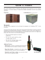
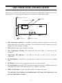
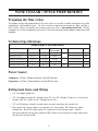
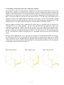
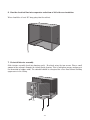
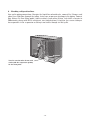
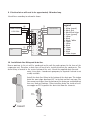
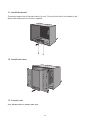
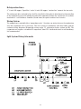
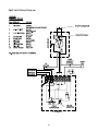
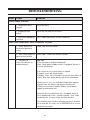
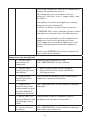
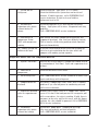
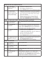
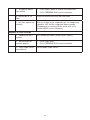
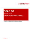
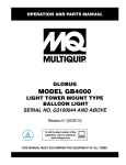
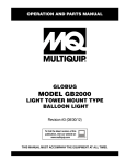
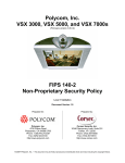
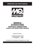
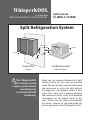
WhisperKOOL
by Vinothèque
“THE COOLEST THING IN WINE STORAGE.”
Split System
SS4000 & SS7000
Split Refrigeration System
Liquid Line
115 VAC
115 VAC
Suction
Drain
Evaporator
Condensing Unit
(Indoor)
(Indoor/Outdoor)
! The WhisperKOOL
Split Cooling System
requires professional
installation by
a Certified HVAC\R
technician.
Thank you for choosing WhisperKOOL Split
Cooling System for your wine preservation
needs. This unit has been specifically designed
and engineered to create the ideal balance
of temperature and humidity within a wine
cellar. This, along with a properly designed
and constructed cellar, creates the optimum
environment for the proper aging of fine
wine. Please take the time to read through
the owner’s manual so you understand the
correct operations of the WhisperKOOL unit.
Copyright ©1998-2008 Vinothèque Wine Cellars All rights reserved.
This manual, the product design, and the design concepts are copyrighted by Vinothèque
Wine Cellars, with all rights reserved. Your rights with regard to the hardware and
manual are subject to the restrictions and limitations imposed by the copyright laws
of the United States of America. Under copyright laws, this manual may not be copied,
reproduced, translated, transmitted, or reduced to any printed or electronic medium or
to any machine-readable form, for any purpose, in whole or in part, without the written
consent of Vinothèque Wine Cellars.
Every effort has been made to ensure that the information in this manual is accurate.
Vinothèque Wine Cellars is not responsible for printing or clerical errors.
Vinothèque Wine Cellars reserves the right to make corrections or improvements to the
information provided and to the related hardware at any time, without notice.
Vinothèque and WhisperKOOLare registered trademarks of Vinothèque Wine Cellars. All
rights reserved.
Mention of third-party products is for informational purposes only and constitutes
neither an endorsement nor a recommendation. Vinothèque Wine Cellars assumes no
liability with regard to the performance or use of these products.
Revised March 1, 2008
TABLE OF CONTENTS
WhisperKOOL Split Cooling System
Features & Benefits....................................................................................... 4
System & Features......................................................................................... 5
PDT Thermostat Operating Instructions...................................................... 6
Package Contents........................................................................................... 7
Wine Cellar / Space Preparation................................................................... 8
Technical Specifications................................................................................. 8
Split System Installation Guidelines............................................................. 9
Condensing Unit Skid Preparation........................................................10
Head Pressure Control, Low Ambient Control Switch...........................11
Mounting the Evaporator Unit.............................................................. 12
Split System Wiring Schematic.............................................................19
Refrigeration Lines...............................................................................19
Wiring system...................................................................................... 19
Charging the system........................................................................... 21
Maintenance.................................................................................................. 21
Technical Assistance.................................................................................... 22
Troubleshooting........................................................................................... 23
Installation Terms and Conditions.............................................................. 28
-3-
FEATURES & BENEFITS
Designed specifically for wine storage, the WhisperKOOL system is a specialized refrigeration unit
designed for one purpose only: to maintain the optimal temperature and humidity levels conducive
to the proper aging of fine wines.
Humidity Control
As the temperature begins to drop within the cellar, the relative humidity will rise. The WhisperKOOL
units do not create humidity. If you live in a dry area of the country, you may need to add humidity
in the wine cellar. This can be done by introducing a non-heat humidifier or installing a small
fountain within the cellar. The WhisperKOOL will remove excess humidity from the air and discharge
it through the drain line hookup on the evaporator unit.
Quiet Operation
Years of experience with our self contained cooling units has resulted in a totally new design which
accounts for a number of environmental conditions unique to wine cellars. We have accounted
for these variables and incorporated the use of state of the art components which offer quiet and
sophisticated operations while keeping the basic concept rather simple.
Condensing Unit Installation, Indoors or Outdoors
This system offers the option of installing the condensing unit indoors or outdoors. This will
allow home builders and architects to incorporate this system with the utmost ease with regard to
installation and space requirements. Note: Exterior installations require a condensing unit
housing. Please specify the need of this requirement at the time of order.
Temperature Differential
The WhisperKOOL split system is designed to operate effectively when the condensing unit (outdoor
section) is running in an ambient temperature of up to 125 degrees. At this extreme condition,
the system is able to maintain a 70 degree differential between the Wine Cellar temperature at
55 degrees and the 125 degree ambient temperature. This is a significant improvement over most
cooling units designed for wine storage.
-4-
System & Features
The system includes both the evaporator and condensing units packaged in two (2) separate
containers. An exterior housing is required for outdoor installations and will arrive packed
separately.
Evaporator
Condensing Unit (Shown With Housing)
Thermostat
The split system evaporator has been designed to incorporate the Vinothèque PDT ™ series
thermostat.
Years of research and testing have gone into the design of the PDT thermostat resulting in advanced
microprocessor controlled digital technology and pinpoint accuracy. This system incorporates a
probe designed to measure the liquid temperature in a wine bottle rather than the air temperature
of the cellar. This results in several distinct advantages:
• Wine is maintained at a precise, measured
temperature.
• The unit will switch on/off less often,
extending cooling unit life.
• The unit will run longer during cycles
effectively maintaining humidity.
Additional Features:
Digital probe - contains a microchip which communicates
back and forth to the thermostat resulting in accuracy.
Heavy Duty Circuitry - designed to resist power surges,
which play havoc on sensitive electrical components.
Fahrenheit and Celsius readout - for use in the United
States as well as around the world.
-5-
PDT Thermostat
PDT OPERATING INSTRUCTIONS
The unit is set at 55°F at the factory. To raise or lower the temperature set point, press the set
button while at the same time pressing either the arrow up or arrow down button.
1
WINE Temperature Indicator
Wine Temperature Reading
WINE
ON
SET
2
3
LED Screen
PDT
55F
Precision digital Technology Thermostat
Temperature
SET
4
5
7
Temperature SET Indicator
Unit ON Indicator
6
UP Arrow Button
8
DOWN Arrow Button
SET Temperature Button
1. Wine Temperature Indicator: A red LED bar will light up when the thermostat is reading the
liquid temperature in the bottle via the probe. This will remain lit and the temperature you see
displayed is what the probe is reading.
2. LED Screen: Displays your thermostat readings.
3. Wine Temperature Reading: The temperature the water bottle is registering to the
thermostat.
4. Temperature SET Indicator: A red LED bar will light up when you are setting the
temperature.
5. Unit ON Indicator: A red LED bar will light up every time the unit turns on to run a cooling
cycle.
6. SET Button: Used to set the temperature you want the unit to maintain.
7. UP Arrow Button: Used with the SET button to set temperature higher. In addition, by pressing
and holding the button it will allow you to see the 5-minute count down.
8. DOWN Arrow Button: Used with the SET button to set temperature lower.
*Up and Down Arrow Buttons used simultaneously will change the temperature read
out from Fahrenheit to Celsius*
-6-
PACKAGE CONTENTS
SS4000
Box 1
Evaporator Unit (part #: 03-4000SS-0120)
Sight Glass
Filter Drier
Box 2
Condensing Unit (part #: 1-122100)
Accessory Kit (par #: 09-950-9997SS)
Box 3
Optional Exterior Housing (part #: 03-4000SS-0120)
Mounting Hardware
Optional Electrical Cover
SS7000
Box 1
Evaporator Unit (part #: 03-7000SS-0120)
Sight Glass
Filter Drier
Box 2
Condensing Unit (part #: 1-122101)
Accessory Kit (part #: 09-950-9997SS)
Box 3
Optional Exterior Housing (part #: 03-7000SS-0120)
Mounting Hardware
Optional Electrical Cover
Accessory Kit
Brass Fitting, 3/8” Barb x 1/8
Brass Nipple, 1/8” Male Pipe
Bypass Plug Jumper w/Molex
Drain Line & Fitting
Owner’s Manual
Screw #8 x 1-3/4 SH Black
part #: 09-950-9997SS
1-141012
1-141025
1-212455
N/A
M-4/7SS RevA
1-422813B
-7-
Quantity
1
1
1
1
1
9
WINE CELLAR / SPACE PREPARATION
Preparing the Wine Cellar
The proper design and preparation of the wine cellar is essential in order to maintain the ideal
temperature and humidity levels. We have created a typical presentation on “How to Build a
Wine Cellar” which is available for viewing on our web site at www.whisperkool.com. Failure
to prepare the cellar accordingly will result in the cellar not maintaining proper temperature and
humidity.
Technical Specifications
Sizing Guide & Specifications
Cellar Volume
Run Amps
SS4000 Condensing Unit
1000 cu. ft.
10.3 Amps
Minimum
Circuit Amps
15 Amps
SS4000 Evaporator
1000 cu. ft.
1.0 Amp
2 Amps
SS7000 Condensing Unit
1750 cu. ft.
12.0 Amps
18 Amps
SS7000 Evaporator
1750 cu. ft.
1.0 Amps
2 Amps
Vinothèque model
Outside Enclosure (All)
NA
NA
NA
Ton
1/3
7/12
NA
HxWxD
Lbs
13.5”x18.5”x12”
56
15.75”x23.5”x15.5”
60
13.5”x18.5”x12”
66
15.75”x23.5”x15.5”
60
20.75”x25.75”x18”
30
Power Source
Condenser -115Volt, 20Amp Dedicated (Non-GFI) Breaker
Evaporator -115Volt, 15Amp Dedicated (Non-GFI) Breaker
Refrigerant Lines and Wiring
• 1/4” OD copper liquid line
• 1/2” OD copper suction line. If longer than 75’, use 5/8” OD pipe. If there is a vertical rise
of more than 10’, reduce to 3/8” OD pipe for the rise.
• 1/2” wall thickness Armaflex (brand name) or equal insulation for suction line
• For suction lines where elbows are required, use “long radius” 90° elbows to reduce
friction loss. Each 90° elbow equals 1ft. equivalent feet of tubing length. Add the
equivalent footage for the total number of 90° elbows to the length of straight tubing with
the total not to exceed 100’.
-8-
SPLIT SYSTEM INSTALLATION GUIDELINES
General Installation Guidelines and Instructions
Vinothèque requires that a certified HVAC technician install and pipe the Split System unit
modules. Please take a moment to review State and City building codes to insure the safe and
proper installation of the unit.
Installing Condensing Unit
The condensing unit can be mounted inside a utility area of the home or outside utilizing the
required outdoor condensing unit housing. The system will operate on a 70 degree temperature
differential. This means that the unit will keep the wine cellar at 55 degrees when the outside
temperature is 125 degrees and will have the capacity to produce cool air into the cellar as long as
the ambient temperature does not exceed 125 degrees Fahrenheit. This unit requires a dedicated
20 amp circuit, non-GFI. Make sure there is a minimum three-foot horizontal clearance in front
and rear of the unit. The unit may either be hard wired or plug-in depending on local electrical
codes.
Internal Condensing Unit Installations. Internal (i.e., inside the building) installations
require special consideration by having adequate ventilation to dissipate the heat created
during normal operations. An exhaust port with fan may need to be installed to assure that
heat is effectively removed from the utility room. A return grille or provision for 500 - 600 cfm
of cool air to enter the room to replace the exhausted air will accomplish this. Unobstructed
airflow to and from the unit is a critical factor in the unit’s overall performance. Make sure
there is a minimum three-foot horizontal clearance in front and rear of the unit. This will
assure that the unit can move the air around the room in an efficient manner.
Outdoor Condensing Unit Installations. You must utilize the exterior condensing unit housing
for outdoor installations. Place the condensing unit on a solid foundation in a location with
adequate ventilation. There should be three feet for clearance in the front and rear of the
unit and one foot on each side. The unit should be elevated 18 inches in order to avoid
any possible flooding or damage by animals, and should be clear of leaves, dirt, and other
debris.
Mounting Evaporator Unit
The evaporator unit should be mounted level and the top of the unit needs to be 6” inches or
less from the ceiling of the cellar in order to deliver sufficient cooling. As the room cools down,
warm air will rise to the ceiling, which is then captured into the cooling unit in order to create
a consistently cool environment. Mounting the unit low in the room will result in a temperature
variation due to cold air puddling on the floor and the unit’s inability to draw warm air down from
the ceiling into the unit itself.
Unobstructed Airflow
Unobstructed airflow to and from the unit is a critical factor in the unit’s overall performance.
-9-
CONDENSING UNIT SKID PREPARATION
Note: The condensing unit is shipped with a protective foam pad/ block to prevent damaging tubing
against the condenser coil fins. Please ensure that this pad is removed prior to operation.
Condensing Unit
-10-
Head Pressure Control, Low Ambient Control Switch:
The switch is used to cycle the condenser fan at low ambient temperature condition. Set the switch
to 170 psig for cut-in and 70 psig for the differential. Further adjustment may be needed. Verify
the settings via refrigeration manifold gauge and perform the final adjustments to the readings on
the gauge manifold.
Low Ambient
Control*
High Pressure
Cutout
Low Pressure
Cutout
Condensing Unit
* Low ambient control is in the control box
-11-
MOUNTING THE EVAPORATOR UNIT
1. Disassemble evaporator unit.
In order to mount the housing to the wall, the internal components will need to be removed and
reinstalled after mounting the housing. Remove front cover and thermostat by unscrewing four
captive screws located on each corner of the cover and five at bottom of front cover.
Note: Thermostat is not plugged into electrical line.
2. Remove interior assembly.
The interior assembly is one piece. The assembly should slide out on mounting rails as one
piece.
-12-
3. Identify and remove appropriate knockouts.
There are knockouts located on the rear panel, right side panel and on top. Remove knockouts for
the two refrigeration lines and install the two grommets supplied. Remove knockout for electrical
line. Keep the refrigerant pipes capped to prevent any foreign material from entering, until ready
to braze.
4. Mounting housing to wall.
The unit has six mounting holes on 16 inch wide centers. Utilize all mounting screws to secure
the housing to the wall (screws not included).
18
6” inches
-13-
5. Installing refrigeration lines into evaporator housing.
With knockouts removed, install grommets supplied. Install housing, mark location and center line
of holes to be drilled in wall. Slide interior into place, measure the distance from the suction and
liquid line connection locations to the housing knockout opening. Add that dimension to the length
of pipe necessary to penetrate the wall for a rear entry plus enough for an elbow connection if the
pipe is to run up or down the wall on the back side of the unit. A 1/2” 90° long radius elbow will be
required to connect to a nipple from the suction line and to either a vertical riser through a ceiling
opening or to extend the pipe through the right side of the housing opening and adjacent wall. Add
enough length for the pipes to pass through the wall and connect to another fitting.
Since the piping is parallel to the evaporator coil and the coil is at an angle with the housing, the
“through the rear” or “side wall pipes” will have to be formed inside the housing to match that
angle prior to connecting. The 90° elbow on the vertical riser can be adjusted to the proper angle
to fit the nipple from the elbow to the coil suction line connection. With measurements taken,
remove the interior assembly and the housing. Drill a 1 1/2” hole for the 1/2” O/D suction pipe plus
the 1/2” wall thickness cellular insulation and 1/4” liquid pipe. Drill necessary hole for electrical
wiring.
Securely cap the piping ends. It is suggested that the pipes be installed from inside the housing;
the insulation slid over the suction pipe outside the housing; the liquid line taped to the outside
of the insulation; and the housing placed in position while guiding the pipes through the wall or
ceiling. Electrical wiring should be pulled through the housing and the housing secured in position
in accordance with instructions on page 13.
Pipes from the back
Pipes from the top
-14-
Pipes from the side
6. Run the electrical line into evaporator on bottom of left side over insulation.
Wires should be at least 36” long going into the cabinet.
7. Re-install interior assembly.
Slide interior assembly back into housing gently. Re-attach using the two screws. Flow a small
amount of dry nitrogen through the tubing during brazing. This is to displace oxygen and prevent
the formation of copper oxide. The solenoid should be energized for a free flow without building
up pressure in the tubing.
-15-
8. Attaching refrigeration lines.
Line up the piping connections. Energize the liquid line solenoid valve, connect Dry Nitrogen, and
adjust to a slight flow through the tubing, being sure no pressure develops in the piping. Connect
flare fittings if a flare fitting model, tighten securely, braze other fittings, leak check, evacuate to
200 microns, charge with R-134 refrigerant, start and check out. Using wire ties, secure tubing as
low as possible in the evaporator so tubing is not visible through air inlet grille.
Note: Be sure the tubes do not stick
out beyond the evaporator opening
for the front panel.
-16-
9. Electrical wires will need to be approximately 36 inches long.
Attach lines according to schematic shown.
Power Source
115V 60Hz
L8
L2
L1
J1
T8
T2
T1
T3
Legend
Thermostat
J1
Fan
F8
F1
F2
J1
S1
S2
Solenoid Valve
L1 - White (neutral)
L2 - Black (hot)
L3 - Black Silver Stripe
L8 - Green (ground)
T1 - White
T2 - Black
T3 - Black / White
T8 - Green
F1 - White
F2 - Black
F8 - Green
S1 - White
S2 - Black
J1 - White Jumper
10. Install drain line fitting and drain line.
Excess moisture in the air will be condensed on the coil fins and captured in the base of the
evaporator unit. Therefore a drain line will need to be installed to drain the condensate. The
drain fitting is located in the center bottom of the unit. Attach the supplied drain line and
route it to a drain. A condensate pump may be required if a drain is not
readily available.
Install the drain line fitting to the bottom of the drain pan. The indoor
drain line must slope downward 1/4” to the foot and have no traps. The
line cannot run higher than the bottom of the drain pan and should not
have any kinks or blockage. When installing drain line inside of wall,
use copper or PVC to protect the drain tube from the elements.
WATER
LEAKING
CORRECT
WRONG
-17-
11. Install thermostat.
Thermostat mounts on the bottom front of the unit. Plug electrical outlet to thermostat and
mount from underneath with screws supplied.
12. Install front cover.
13. Energize unit.
Note: Thermostat has a 5 minute time delay.
-18-
Refrigeration Lines
A 1/4 inch O/D copper “liquid line” and a ½ inch O/D copper “suction line” connect the two units. The refrigerant drier and sight glass shall be installed in that order in direction of refrigerant flow
in the liquid line between the condensing unit and evaporator. Enclose the suction line in a cellular
insulation ½” wall thickness Armaflex (brand name) or equal to reduce heat transfer.
Wiring System
The compressor is controlled by a “pump down cycle,” therefore, no wiring between the condensing
unit and evaporator unit is necessary. Wire the system in accordance with local codes and the
enclosed wiring diagrams (Evaporator wiring on pg 17, schematics below, and on pg 20). The
evaporator unit requires a standard 15 amp circuit, non-GFI. A dedicated circuit is not mandatory,
but recommended.
Split System Wiring Schematic
-19-
Split Unit Wiring Diagram
-20-
!
Charging the System (by Certified HVAC technician)
After all the piping is complete:
• Open both of the service valves on the condensing unit. The unit is pressurized with
Nitrogen and you should hear the gas escaping through the service ports.
• With electrical power connected to the evaporator unit energize the solenoid valve
(pressurize with dry Nitrogen) to 100psi. Leak test all fittings. Must hold 100psi for 30
minutes.
• If no leaks are found, leave solenoid valve energized and evacuate the system through both
the liquid and suction service ports. Using a high vacuum pump, evacuate to 200 microns,
measuring the vacuum with a digital micron gauge. When evacuation is complete, break
vacuum and pressurize with liquid R-134A. refrigerant.
• With the electrical power turned on to the condensing unit, and the evaporator unit
running, slowly feed liquid refrigerant (R134A) into the suction service port. As the
suction pressure rises to 15 PSIG, the condensing unit will start. Slowly feed refrigerant
while maintaining a pressure above 10 PSIG to prevent the compressor from short cycling.
Slowly feed refrigerant with the compressor running until the sight glass is clear of all
bubbles. Do not exceed 3.5 lbs of refrigerant. Check superheat at evaporator outlet.
Superheat should be at 10°-12°. Check the compressor crankcase temperature after 30
minute run time – should be hot 115°to 140°. If cool, superheat is too low. Adjust TXV
to recommended superheat.
• Allow the system to operate for one hour and then check the refrigerant level in the sight
glass again. Additional refrigerant may be required as the temperature of the enclosure
is lowered to approximately 55F or the ambient temperature at the condensing unit rises
above the temperature at which the unit was initially charged. Depending on temperature,
the “high side” should be approximately 175 lbs. The ”low side” 28 lbs or more to keep
the evaporator from icing. It is recommended while charging to use a digital refrigerant
scale for better accuracy in measuring the amount of charge.
Maintenance
The WhisperKOOL system is designed to operate with very little maintenance required. Do check
the condensing unit and evaporator coils, and vacuum them every three months.
-21-
TECHNICAL ASSISTANCE
Vinothèque Customer Service is available Monday through Friday
from 8:00 a.m. to 4:00 p.m. Pacific Time.
Please make sure that you have the following information available
before you call:
• The model and serial number of your WhisperKOOL unit.
• Type of thermostat used with your WhisperKOOL.
• Location and installation details, such as ventilation, construction,
and size of room.
How To Contact Vinothèque Customer Service
Telephone
(209) 466-9463 (800) 343-9463
Fax
(209) 466-4606
Web site
www.Vinothèque.com
Address
Vinothèque Wine Cellars
1738 East Alpine Avenue
Stockton, CA 95205
-22-
TROUBLESHOOTING
Fault
Cause
Solution
Water leaking from unit
1. Condensate drain
clogged
Clear out drain
2. Evaporator coil
frozen
Clean the coil and / or fan wheel
3. Drain line improperly
installed
Call a CERTIFIED HVAC service technician.
Wine cellar temperature above thermostat set point
1. Large quantity of
warm wine placed in
cellar
Allow time for wine to cool
2. Wine Cellar Door left
open for long period.
Close Door. Allow time for wine to cool.
3. No power to
either fan coil unit or
condensing unit
Fan Coil
Is the thermostat display illuminated?
If not, check power supply switch, if equipped. Ensure it
is in the ON position.
If on, check to see in the breaker is tripped.
If tripped, reset and check display.
If display “Wine” bar is illuminated, wait for time delay to
expire. Wine light blinks during time delay countdown.
Check to see if “On” bar indicator illumination appears
at which time the blower and cooling should start
If blower starts and no cooling follows, check power
supply to condensing unit.
Check breaker to condensing unit. If tripped, check to
see if compressor is hot – too hot to touch. If so, allow
to cool for one (1) hour before resetting breaker.
After cooling, reset breaker and note whether it remains
set or trips off. If it trips, call a CERTIFIED HVAC service
technician for repair.
gj
-23-
If the breaker remains set, check to see if compressor is
running and condenser fan turns on.
After compressor runs a few minutes, check the
refrigerant “sight glass” in the ¼” copper tubing. Look
for bubbles.
If no bubbles are present and compressor is running,
refrigerant system is running OK.
If bubbles are present, system is low on refrigerant.
A CERTIFIED HVAC service technician will have to locate
and repair any refrigerant leaks, then add refrigerant.
Condenser fan should come on either immediately on
compressor start or after sight glass gets warm.
If not, compressor will trip off on high pressure safety
control, reducing capacity and possibly tripping the
breaker.
In this event, CERTIFIED HVAC service technician will
have to check for the problem.
Compressor runs intermittently
1. Fan coil blower
not running with
compressor
Evaporator coil will probably be iced.
Call a CERTIFIED HVAC service technician.
2. Fan coil blower
running too slow or air
flow blocked.
• Increase speed control setting if equipped.
• Clean coil if necessary, remove obstructions.
• Coil icing can occur.
3. Condenser coil
blocked with dirt or
other matter.
Clean coil and fan thoroughly, clear any obstructions
and/or cause for hot air recirculation.
4. Condenser fan
motor bearings faulty
causing motor to trip on
overload, followed by
compressor cycling off.
Call a CERTIFIED HVAC service technician to diagnose
and repair.
5. Hot air, above 125°,
entering condenser from
confined space (outer
room)
Provide source of cool air to condenser space in
accordance with directions in this manual.
6. System refrigerant
overcharge.
Call a CERTIFIED HVAC service technician to diagnose
and recover excess refrigerant.
-24-
7. System low on
refrigerant.
Check refrigerant “sight glass” in 1/4” tubing.
Check for bubbles after system has run for several
minutes. If bubbles present, call a CERTIFIED HVAC
service technician. If sight is clear of bubbles,
refrigerant level is OK.
8. Thermostatic
expansion valve power
element losing its
charge.
System will operate as if it were low on refrigerant
charge. Sight glass will be clear. Evaporator coil icing
probable.
Call a CERTIFIED HVAC service technician.
9. Low voltage to
compressor, below
103V with compressor
running.
Low voltage will cause compressor overheating and
tripping on overload. Also, can have difficulty starting.
This is usually a field wiring problem which should be
corrected immediately.
10. Cooling system not
sufficient for load
If system is determined to run OK but not keeping up,
run a heat gain calculation for the wine cellar and
compare with cooling system capacity.
Evaporator blower runs, but compressor does not
1. System “Anti-Frost“
Observe for several minutes. Compressor should turn on
at termination of “Anti Frost“ Cycle and evaporator clear
of frost.
2. Power off to
compressor.
Check breaker/Refer to #3 above
3. Out of refrigerant.
Call a CERTIFIED HVAC service technician to locate leak,
repair and charge with refrigerant
4. Compressor off on
overload.
Determine if compressor is hot. If not, there is another
problem. If yes, shut off power to condensing unit and
call service technician
5. Liquid line solenoid
valve in evaporator not
active.
Remove cover. Locate valve in ¼” copper tube. Check
to see if it is hot. If hot and you can feel a magnetic pull
with a screwdriver, the valve is working. If cold, there is
no power to the valve coil. In this event, with the blower
running, the valve should be powered. Call a CERTIFIED
HVAC service technician.
6. Thermostat
expansion valve power
element lost charge
System will “pump down.” Compressor will stop.
May start occasionally and shut off quickly.
Call a CERTIFIED HVAC service technician.
-25-
Compressor runs, but evaporator does not
1. Faulty blower
motor or broken wire
connection
• Evaporator coil probably frozen
2. Defective low
pressure switch not
shutting compressor off
when pressure drops
• Compressor would continue to run when thermostat
is satisfied and shuts blower and solenoid off. When
space warms up to set point, blower starts and the
system runs normally.
• Shut off power to condensing unit
• Call a CERTIFIED HVAC service technician for repair
• Prolonged running without refrigerant flow will
damage or destroy compressor. If this condition
exists, call a CERTIFIED HVAC service technician.
Compressor short cycles, which is different from running intermittently
1. System pressure
controls defective.
Call a CERTIFIED HVAC service technician to verify and
repair.
2. System low on
refrigerant.
Observe for flashing in refrigerant sight glass located
in 1/4” copper tube at condensing unit. If flashing with
bubbles, call a CERTIFIED HVAC service technician for
leak location, repair, and adding refrigerant.
3. Condenser fan motor
defective
• Fan does not run with compressor.
• ¼” copper tube at sight glass – very hot, compressor
very hot, runs short time, shuts off.
• Shut power off to condensing unit
• Call a CERTIFIED HVAC service technician for repair.
4. Compressor starting
components defective.
• Compressor very hot and hums when trying to start.
• Shut power off to condensing unit.
• Call a CERTIFIED HVAC service technician.
Evaporator coil freezes
1. Air filter, if
equipped, dirty
Clean or replace filter
2. Evaporator coil and/
or blower dirty
Clean coil and blower
3. Thermostat set point
too low.
Set point should not be lower than 50°. If so, increase to
above 50°
4. System low on
refrigerant
Check refrigerant “sight glass” in 1/4” tubing. Check
for bubbles after system has run for several minutes. If
bubbles present, call a CERTIFIED HVAC service technican.
If sight is clear of bubbles, refrigerant level is OK.
-26-
5. Evaporator blower
not running
• Faulty blower motor or broken wire connection.
6. Obstruction to air
flow
Check for obstruction to air flow and repair
7. Anti-frost control not
working
With ice or frost in the evaporator coil, the compressor
should be OFF and the evaporator blower running.
If compressor is running with ice on the coil, call a
certified HVAC service technician.
• Call a CERTIFIED HVAC service technician
Humidity in cellar too high
1. Compressor short
cycling
See Compressor Short Cycling Subject (above)
2. Refrigeration not
running properly
• Check items above
• Call a CERTIFIED HVAC service technician
3. Cellar vapor barrier
not sufficient
Install proper vapor barrier
-27-
WhisperKOOL SPLIT SYSTEM
INSTALLATION TERMS AND CONDITIONS
PLEASE READ THESE TERMS AND CONDITIONS CAREFULLY BEFORE INSTALLING YOUR WhisperKOOL
Split System.
1. Acceptance of Terms & Conditions
Installation and use of a WhisperKOOL Split System (hereafter referred to as “the product”)
constitutes acceptance by the Purchaser (or user) of the Terms and Conditions set forth in this
document. The WhisperKOOL Owner’s Manual is shipped with each unit and if another copy is
needed, replacement copies can be downloaded from the company web site (www.Vinothèque.
com) or by contacting Vinothèque Wine Cellars (“Vinothèque”) directly for a new copy. Vinothèque
reserves the right, in its sole discretion, to change its Terms & Conditions at any time, for any reason
without notice.
2. Product Installation
(a) Purchaser of the product must arrange for the product to be installed by a certified HVAC
technician in accordance with procedures set forth by Vinothèque and described in the
WhisperKOOL Owner’s Manual.
(b) Purchaser must return the Limited Warranty card to Vinothèque to register the product and
obtain the benefits of the Limited Warranty throughout the warranty period. Failure to register
the product within thirty (30) days of installation may result in loss of warranty.
(c) The HVAC technician installing the product must complete the designated portion of the Limited
Warranty card and provide licensing or certification identification number information to
Vinothèque in order to validate the Limited Warranty.
(d) Purchaser is responsible for the full costs of installation and any additional parts required for
the proper and complete installation of the product.
3. Product Warranty Information
For Split Systems returned to Vinothèque in accordance with the terms and conditions of the Limited
Warranty, Vinothèque warrants against defects in material and workmanship as follows:
(a) LABOR: For a period of two (2) years commencing on the date of purchase, Vinothèque will, at
its option and discretion, either repair or replace the product at no charge to the Purchaser if the
product is determined by Vinothèque to be defective. After the Warranty period, the Purchaser is
responsible for all labor charges.
(b) PARTS: For a period of two (2) years commencing on the date of purchase, Vinothèque will
supply, at no charge, new or rebuilt replacement parts in exchange for defective parts.
(c) FREIGHT: For a period of two (2) years commencing on the date of purchase, Vinothèque will
cover freight charges incurred in connection with the repair of units then under warranty to
customers within the continental United States.
-28-
Vinothèque’s Limited Warranty does not cover damage to the product caused by third parties or
damage due to acts of God, accident, misuse, abuse, negligence, or modification of, or to any part of
the product. The Limited Warranty does not cover damage due to improper operation or lack of proper
maintenance, connection to improper voltage supply, or attempted repair by anyone other than an
HVAC technician approved by Vinothèque to service the product. The Limited Warranty does not cover
Products sold “as is” or “with all faults” and is valid only in the United States.
Proof of purchase (in the form of a bill of sale or receipted invoice) establishing that the product is
within the warranty period must be presented to obtain warranty service.
This Limited Warranty is invalid if the factory-applied serial number has been altered or removed
from the Product.
REPAIR OR REPLACEMENT PURSUANT TO THE LIMITED WARRANTY IS THE EXCLUSIVE
REMEDY OF THE CONSUMER FOR ANY DEFECTS IN VINOTHÈQUE PRODUCTS. VINOTHÈQUE
SHALL NOT BE LIABLE FOR ANY INCIDENTAL OR CONSEQUENTIAL DAMAGES ARISING FROM
THE BREACH OF ANY EXPRESS OR IMPLIED WARRANTY ON THIS PRODUCT, EXCEPT TO THE
EXTENT PROHIBITED BY APPLICABLE LAW, ANY IMPLIED WARRANTY OF MERCHANTABILITY
OR FITNESS FOR A PARTICULAR PURPOSE ON THIS PRODUCT IS LIMITED IN DURATION TO
THE DURATION OF THIS WARRANTY.
Some states do not allow the exclusion or limitation of incidental or consequential damages or on the
duration of express and/or implied warranties, so the above limitations or exclusions may not apply to
you.
Vinothèque’s Limited Warranty gives you specific legal rights and you may have other rights, which
vary from state to state.
4. Maintenance
The Purchaser or user is responsible for checking the coils on the condenser unit and vacuuming
them every three months to maintain them free of debris. The drain tube and the heater pan located
on the evaporator unit must also be checked and kept clean and free of debris and mold to maintain
proper performance.
Mold is a natural living organism in the environment. It exists in the air in the form of
microscopic spores that move in and out of buildings through doors, windows, vents, HVAC
systems and anywhere else that air enters. Once it is discovered, mold must be addressed
quickly and appropriately. Delayed or improper treatment of mold can result in costly and
recurring repairs. If you suspect you have a mold problem, it is always best to hire a qualified
and experienced mold remediation specialist.
5. User Costs and Responsibility
Responsibilities of the Purchaser, and/or items not covered under our Limited Warranty, include,
but are not limited to, the following:
(a) All initial installation costs, including, but not limited to, labor costs and the cost of any
additional parts necessary to complete the installation.
(b) Users must assure that the product is installed by a certified HVAC technician. Failure to do so
will result in Voiding the Limited Warranty.
(c) All costs incurred for the installation and/or removal of the product, or any part thereof, unless
such cost has been defined as a warranty repair prior to the work being performed.
-29-
(d) Purchasers should satisfy themselves that the product they are purchasing is suitable for their
needs and requirements.
(e) Purchasers are responsible for assuring the safety of any and all items that are kept and stored
in the wine cellar. Vinothèque takes no responsibility for the safety of such items in the event
that the environment becomes unsuitable for proper storage.
6. Customer Service
Vinothèque customer service department is available Monday through Friday, from 8:00 a.m. to 4:00
p.m. Pacific Time and can be reached at 1-800-343-9463.
7. Troubleshooting
The customer service department is available to answer questions regarding our products and to
assist in basic troubleshooting in the event that a problem arises.
Vinothèque reserves the right to have a certified, Vinothèque-approved, HVAC technician go on site
and inspect the product if the initial trouble shooting warrants further investigation.
If after on-site inspection of the product, it appears the product may be malfunctioning due to a
defect in the unit, Vinothèque will cover the costs of the evaluation by the certified HVAC technician.
If the product is malfunctioning due to the improper installation or some other act or omission by a
party other than Vinothèque, then the user is responsible for the costs of the on-site evaluation by
the technician in addition to any repair costs.
8. Request for Product Evaluation and Repair Under Warranty
8.1 Split System Field Service Warranty Policy
This Policy is to clarify what falls under Warranty Service and what becomes the responsibility
of the Owner. Vinothèque (“manufacturer”) strives to provide our customers with a superior
product and we back our product with a Two Year Limited Warranty. Please review the
following guidelines to ensure you have a complete understanding of our Policy and coverage
of your Split System. Vinothèque will respond to your request for service once this letter has
been signed and returned to the manufacturer.
8.2
Product Warranty Information
(a) LABOR: For a period of two (2) years from the date of purchase, if this Product is determined
to be defective after undergoing customer service troubleshooting, Vinothèque will repair
or replace the Product, at its option and discretion, at no charge to the customer. After
the Warranty Period, the customer is responsible for ALL labor charges.
(b)
PARTS: Vinothèque will supply, at no charge, new or rebuilt replacement parts in
exchange for defective parts for a period of two (2) years which include, but are not
limited to, Evaporator Coil, Evaporator Side Fan, Evaporator Solenoid Valve, Thermostat,
Condenser Sid Fan, Condenser Side Fan Switch, Compressor, Head Pressure Control,
Low Pressure Switch, Condenser Coil, Access T’s, Sight Glass, Liquid Line Drier, High
Side Receiver.
(c) FREIGHT: For a period of two (2) years from the date of purchase, Vinothèque will cover
freight for the repair of units UNDER WARRANTY to customers within the continental
United States.
-30-
8.3
Product Installation
The following parts or causes of failure are not the responsibility of the manufacturer:
improper voltage supply, line set with screw connectors (high end and low end), leaks found
at the braze points when performing pressure check, unit that has been charged incorrectly,
incorrect tubing diameter used on line set, a unit that has been wired incorrectly. (Refer
to page 19 of Split System Manual), valve stem on condenser side, improper installation of
P-Trap or lack of P-Trap if required (Refer to page 8 of Split System Manual), condenser
installed outdoors, or in elements that would affect operation, without proper cover or
housing. (Housing is available from Manufacturer)
8.4 User Costs and Responsibility
The following items are not covered under warranty and are the sole responsibility of the
user:
(a) Costs incurred for the installation and removal of the product.
(b) Purchasers (users) are reminded that they should satisfy themselves that the product
they have purchased is suitable for their needs and requirements and no responsibility
will be placed with Vinothèque for their decisions.
(c) It is the user’s responsibility to secure safe haven/storage for ANY AND ALL items that
are being kept and stored in the user’s wine cellar. Vinothèque takes no responsibility for
the safety and preservation of the aforementioned items in the event that the environment
becomes unsuitable to maintain proper storage.
8.5
Arbitration
Any disputes arising out of or in connection with the installation and warranty of the Split
System shall be referred to and finally resolved by a Vinothèque approved Independent
Certified HVAC Technician. The evaluation of the Technician on all issues or matters of
identifying the responsible party (Vinothèque or Installing Technician) shall be determined in
a written report. This report will be made available to all concerned parties. If discovered
under warranty, Vinothèque will assume the financial responsibility under their warranty
guidelines. If the report finds the Owner’s Installer as the responsible party, Vinothèque will
provide all documentation to the customer to substantiate the findings. This will include
the Invoice from the Independent Certified HVAC Technician and the written report of the
findings. The Owner will become responsible for payment directly to Vinothèque for all
charges incurred for repairs (labor, parts and shipping costs) on the Split System.
9. General Provisions
Responsibilities of the Purchaser, and/or items not covered under our Limited Warranty, include,
but are not limited to, the following:
(a) CONSTRUCTION AND SEVERABILITY: Every provision of these Terms and Conditions will be
construed, to the extent possible, so as to be valid and enforceable. If any provision of these
Terms and Conditions so construed is held by a court of competent jurisdiction to be invalid,
illegal or otherwise unenforceable, such provision will, to the extend so held, be deemed
severed from these Terms and Conditions, and all other provisions will remain in full force and
effect.
-31-
(b) GOVERNING LAW/ CHOICE OF FORUM: The laws of the State of California (without regard for
conflicts of law) shall govern the construction and enforcement of these Terms and Conditions,
except that the Terms and Conditions shall be interpreted as though drafted jointly by
Vinothèque and the Purchaser. Any dispute will be resolved in a state or federal court situated
in the County of Santa Clara, State of California, and the Purchaser hereby irrevocably submits
to the personal jurisdiction of such courts for that purpose.
(c) ENTIRE AGREEMENT/ NO WAIVER: These Terms and Conditions and the Limited Warranty
incorporated herein by reference set forth the entire agreement between the parties and
supersede all prior agreements or understandings, both written and oral, between the parties
regarding the subject matter of this the Terms and Conditions and Limited Warranty. The
parties may modify these Terms and Conditions or the Limited Warranty only in writing signed
by each. No waiver by Vinothèque of any breach or default hereunder will be deemed to be a
waiver of any preceding or subsequent breach or default.
(d) CORRECTION OF ERRORS AND INACCURACIES: These Terms and Conditions may contain
typographical errors or other errors or inaccuracies. Vinothèque reserves the right to correct
any errors, inaccuracies or omissions, and to change or update these Terms and Conditions at
any time without prior notice.
10. Questions or Additional Information
If you have any questions regarding these Terms and Conditions, or wish to obtain additional
information, contact us via phone at 1-800-343-9463 or please send a letter via U.S. Mail to:
Vinothèque Wine Cellars
1738 E. Alpine Ave.
Stockton, CA 95205
-32-
-33-
1738 East Alpine Avenue
Stockton, California 95205
www.Vinothèque.com