1
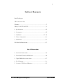
D.W. FEARN
VT-1
VT-2
Vacuum Tube Microphone
Preamplifiers
Operating Instructions
How to Contact us:
Telephone: 610-793-2526
Fax: 610-793-1479
Mail: P.O. Box 57, Pocopson, PA 19366 U.S.A.
Shipping Address: 182 Bragg Hill Road
West Chester, PA 19382 U.S.A.
e-mail: [email protected]
www.dwfearn.com
D.W. FEARN
VT-1 & VT-2 Microphone Preamplifers
D.W. FEARN
www.dwfearn.com
H AND - CRAFTED
PROFESSIONAL
RECORDING EQUIPMENT
P.O. Box 57
Pocopson, PA 19366 U.S.A.
Tel: 610-793-2526
Fax: 610-793-1479
Certificate of RoHS Compliance
D.W. Fearn is committed to manufacturing products that are fully-compliant with
the EU RoHS Directive.
The following products are compliant:
VT-1
VT-2
VT-3
VT-4
VT-7
VT-15
LP-1
PDB
This declaration is based on our understanding of the current RoHS Directive and
from information provided by the supplier material declarations with regard to
materials contained in the component that make up our products.
Douglas W. Fearn
President
4
5
VT-1 / VT-2 Vacuum Tube Microphone Preamplifier
Final Test Report
Model _______________ Serial Number_______________Mains Voltage ______________
Date ___________________ Tested by ________ VU Calibrated to _______________ dBm
Test Equipment ____________________________ Microphone ________________________
Channel b
Channel A
Frequency Response:
Frequency Response:
20 cps to 20 kc/s +/- ___________ dB
20 cps to 20 kc/s +/- ___________ dB
THD+Noise:
THD+Noise:
20 cps ______________ %
20 cps ______________ %
200 cps _____________ %
200 cps _____________ %
2 kc/s _______________ %
2 kc/s _______________ %
20 kc/s ______________ %
20 kc/s ______________ %
Noise:
Noise:
______________ dB below +4 dBm out
______________ dB below +4 dBm out
Equivalent Input Noise _______ dB
Equivalent Input Noise _______ dB
Operational Tests:
Operational Tests:
-20 pad ________________
-20 pad ________________
Lo-Z input ______________
Lo-Z input ______________
Phase Reverse __________
Phase Reverse __________
+48V ___________________
+48V ___________________
Listening Test ____________
Listening Test ____________
VT-1 & VT-2 Microphone Preamplifers
D.W. FEARN
7
Table of Contents
Final Test Report
CE Certification Data
Warranty .........................................................................................7
History of the VT-1 and VT-2 ..........................................................9
1. Specifications ..........................................................................13
2. Description...............................................................................15
3. Installation ......................................................................17 21
5. Theory of Operation ................................................................29
6. Maintenance ...........................................................................33
LP-1 Line Pad Instructions ............................................................37
List of Illustrations
1. Rear Panel Connections .......................................................... 18
2. Front Panel Controls and Indicators ........................................21
3. Typical Studio Interconnections ............................................ 27
4. Block Diagram ........................................................................30
5. Location of VU Meter Calibration ...........................................35
VT-1 & VT-2 Microphone Preamplifers
D.W. FEARN
8
D.W. Fearn shall not be liable for technical or editorial errors or omissions in this
manual, nor for incidental or consequential damages resulting from the use of this
material.
This instruction manual contains information protected by copyright. No part of this
manual may be photocopied or reproduced in any form without prior written consent
from D.W. Fearn.
Copyright ©1995-2004 D.W. Fearn & Associates
D.W. FEARN
VT-1 & VT-2 Microphone Preamplifers
9
Limited 5-Year Warranty
During the warranty period, D.W. Fearn will, at no additional charge, repair or replace
defective parts with new parts.
This warranty does not extend to any VT-1 or VT-2 that has been damaged or rendered defective as a result of accident, misuse, or abuse; by the use of parts not manufactured or supplied by D.W. Fearn; or by unauthorized modification of the VT-1 or
VT-2. Vacuum tubes are excepted from the 5-year warranty, but are warranted for 90
days from date of purchase.
Except as expressly set forth in this Warranty, D.W. Fearn makes no other warranties, express or implied, including any implied warranty of merchantability and fitness for a particular purpose.
VT-1 & VT-2 Microphone Preamplifers
D.W. FEARN
11
History of the VT-1 and VT-2
Vacuum Tube Microphone Preamplifiers
ONE DAY IN 1991 I was going through some old masters in a closet at home and
came across a reel from 1968. It was one of the first studio recordings I ever made.
I pulled the tape box off the shelf and thought about those days. Although I suspected that the recording might be a bit crude, I remembered that the music was pretty
good, so I made a cassette to listen to in the car.
I kept forgetting to put the cassette in my pocket for a few days, but finally I remembered to take it. That old recording brought back memories of my first studio — and
how primitive a setup it was. But listening to that tape was a revelation; some of the
sounds were really nice. The vocals were full and warm but still punched through.
Acoustic guitars had a depth I don’t often hear in current recordings. And the sax
solo — wow! It ripped through with a grossly distorted but beautifully powerful sound.
That recording was done on a 4-track Scully 280 and mixed to a 2-track Scully. My
prize microphone was a Neumann U-87 and that’s what was probably on the featured
instrument or voice on each track. Nothing too unusual about that.
I couldn’t afford the Electrodyne board of my dreams back then. In fact, I built the
“mixer” myself. It consisted of half a dozen RCA tube microphone preamplifiers that
I salvaged from the junk pile of the radio station where I worked, an equal number of
old Daven rotary faders, and key switches that “panned” the output to left, center, or
right.
It was the tube preamps that made that recording sound so good. There was no EQ,
no reverb, but maybe just a touch of compression on some sounds, from an old broadcast type (tube) limiter.
These preamps were 1940s vintage. They used octal metal tubes with a shielded grid cap, a
cylindrical output transformer the size of a coffee can, and a huge power supply on a separate chassis. They were a lot of trouble — the tubes were microphonic and the output was
often noisy. In addition to the hums and hisses, occasionally a take would be ruined by crackles and bangs from the tubes. I couldn’t wait to get rid of the things.
And so I did, not long after. I got a beautiful console with IC op amps, linear faders, real panpots, echo sends and returns, and EQ on every input. No more noisy tubes for me.
But now, 25 years later, I got to thinking about the sound of those tubes. Hit them with a bit
of excessive level and the sound became real fat. Hit them with just the right level and they
sounded warm and intimate.
Could that sound be duplicated today? I dug out my old RCA Receiving Tube Manual and
several other old reference books and reviewed the vacuum tube theory I hadn’t thought
about for years. A quick check in the supplier’s catalogs confirmed that tubes were still easy
to obtain.
VT-1 & VT-2 Microphone Preamplifers
D.W. FEARN
12
Over the years much has changed in the world of electronic components. Were the necessary
parts still available? I found out that they were (though not necessarily cheap) and, in many
cases, they were vastly better than the components available back in the age of vacuum tubes.
Carbon resistors could be replaced with quieter metal film types. Sonically superior polystyrene and polypropylene capacitors were preferable to the old paper types. The power supplies could be solid state — and easily regulated. Electrolytic filter capacitors were smaller.
The only parts that remained to be found were top quality audio transformers that matched
the tube input and output impedances.
A call to the great folks at legendary Jensen Transformers revealed that not only were the
necessary transformers still available but that they were orders of magnitude superior to the
technology of the ‘50s and ‘60s.
A couple of months research into the classic tube mic preamp designs gave me a good idea
of how to proceed. A breadboard prototype was constructed and tested, and it worked great!
(Although the open construction resulted in some RFI; while experimenting with different
component values one night with a pair of headphones on the output, I heard a half hour of
Radio Havana coming through weakly but clearly.) Professional quality specs on frequency
response, distortion, noise, phase shift, and so on were definitely attainable.
Now it was necessary to squeeze the last dB of performance out of the circuit. Computer
circuit analysis was one tool not available to the designers of the original equipment, and it
was amazing how careful manipulation of values could make a significant improvement in
performance.
The next prototype was built and its performance was even better, largely because of better shielding and a better layout. This one became the testing ground for additional experimentation. There is not a single component in that prototype that hasn’t been changed in an
attempt to improve performance. Some parts of the circuit have been through dozens of iterations. Modern test equipment can quantify and graph parameters that had not even been
discovered back in the heyday of “hollow state.”
This prototype became my preamp of choice for all my recording. I used it (and another
one I built soon after) for a year of location recording, mostly of classical and choral music,
but also for studio sessions. Although I have some very fine commercial and homebuilt mixers, after using the tube preamp, I just couldn’t bring myself to use the solid state preamps
anymore.
Why do tubes sound better? All properly designed audio amplifier circuits exhibit low distortion throughout their operating amplitude range. The difference in sound is particularly evident when the circuit runs out of headroom. Solid state devices tend to abruptly transition
from low distortion to extreme distortion (clipping). This is a good trait, since when operated right up to their maximum level solid state amplifiers can maintain excellent performance.
Digital audio circuits have similar characteristics.
Vacuum tube circuits, on the other hand, show a gradual increase in distortion throughout
their operating range. But instead of an abrupt break, the distortion increases incrementally. Until a level is reached where something in the circuit just completely falls apart (e.g. a
transformer saturates), the sound retains most of its original quality.
It’s the nature of the distortion that makes a difference, too. Solid state circuits run out of
headroom when the output voltage exceeds the power supply voltage. The result at this point
D.W. FEARN
VT-1 & VT-2 Microphone Preamplifers
13
is gross distortion — the output becomes a square wave. Square waves are not found in sounds
that we consider musical, so our ears’ response to them is negative.
When a tube circuit distorts, the primary distortion product is even order harmonics. It so
happens that musical instruments also produce primarily even harmonics. By definition,
that’s what makes them “musical.” So you could say that tube circuits can add a musical
component to recorded sound. Fortunately, you can take your choice — keep the level reasonable and obtain good clean audio, or run the circuit into distortion and generate some
harmonics that weren’t there to begin with.
There may be other factors at work, too, that make vacuum tube amplifiers sound different,
even when operated in the low distortion part of their range. I have not proven any of these
esoteric theories to myself yet, but I think they have merit. Here’s one: perhaps the minimal
number of active devices in the signal path makes a difference. My preamp has only four
active devices, while even the simplest solid state op amp circuit may have dozens.
But back to the story ....
Finally the preamp was ready for some serious testing in the studio. A number of friends in
the music business, both musicians and studio owners, were intrigued with the possibilities
of this device, so it was easy to get volunteers to test, evaluate, and give me additional input
on the performance. This resulted in a few more changes that have been incorporated into
the final design.
The VT-1 represents, I believe, not only the best performance attainable with this type of
circuit, but it will meet or exceed the performance of today’s top-of-the-line solid state
designs, while still providing the clarity and musicality that characterizes vacuum tube
“sound.” Not only that, but it is built to last. Solid construction is used throughout, and only
the best parts are used, many of them Mil-spec.
I have found over the years that one insidious source of distortion in the recording studio
comes from connectors, switches, relay contacts, patch jacks, etc. Although these connections may be perfectly adequate when new, after a period of time the contacts oxidize and get
a little dirty. Individually they may not cause much of a problem, but put your audio through
a few of them and you will start to hear the degradation.
To avoid this, the VT-1 design eliminates as many of these trouble-prone connections as possible. In fact, the only non-soldered connections from input to output are the input select and
phase reverse switches and the tube sockets. The input and phase switches are rotary types
with ceramic insulation and massive silver contacts. The phase switch is in the output circuit,
at line level, rather than on the input at very low level. In addition, the switches are chemically treated. And should they ever need cleaning, it is very easy to do a thorough job.
SO DOES THE VT-1 DUPLICATE the sound of my old RCA tube preamps? No, not exactly.
Gone are the hum, hiss, crackles, and bangs. And although I don’t have the old preamps to
do an AB comparison of the sound, I am certain that the better modern passive components
give the VT-1 a superior sound. The VT-1 has been used for all types of recording — vocals,
announcers, acoustic instruments, electric instruments, classical — and it works well with
them all.
VT-1 & VT-2 Microphone Preamplifers
D.W. FEARN
14
The VT-2 was developed in 1995 in answer to requests from a number of our customers for
a two-channel version of the preamp. The VT-2 occupies the same amount of rack space, but
is four inches deeper than the VT-1.
D.W. FEARN
VT-1 & VT-2 Microphone Preamplifers
15
1.
S P E C I F I C AT I O N S
Input
150 ohms
Input Load
Impedance
1.5k ohms
Minimum Input
Level
-65 dBm nominal
Maximum Input
Level @ 20 cps
Gain
Frequency
Response
-30 dBm without pad
-5 dBm with 20 dB pad
53 dB minimum
± 0.2 dB 20 cps to 20 kc
± 0.5 dB 11 cps to 28 kc
-3 dB @ 0.5 cps & 50 kc
THD + Noise
<0.25% 20 cps to 20 kc
Intermodulation
Distortion
SMPTE: <0.80%
Signal to
Noise Ratio
74 dB minimum
Equivalent
Input Noise
-124 dbm maximum
Output
low-Z, transformer balanced
Maximum
Output Level
+22 dBm unterminated
Power
Requirements
100, 120, or 220 VAC
50/60Hz, 25 W
Dimensions
19” (48.26cm) W
5.25” (13.34cm) H
9” (22.86cm) D (VT-2 13” 22.9cm)
Weight
VT-1 14 lbs (6.35 kg)
VT-2 18 lbs (8.16kg)
VT-1 & VT-2 Microphone Preamplifers
D.W. FEARN
17
2.
DESCRIPTION
The Model VT-1 and VT-2 Vacuum Tube Microphone Preamplifiers are designed to provide
recording professionals with a sonically superior input device. (Unless there is a specific reason to address a difference between the VT-1 and VT-2 preamplifiers, the device will be
referred to as the “VT-2.”) It is typically used in sound recording studios for recording individual tracks. A quality microphone is connected to a VT-2 input, and the VT-2 provides a
line-level output. In most situations, the VT-2 will feed directly to the input of the recorder.
The VT-2 is a recreation of the classic tube preamps of the 1960s, updated with improved
modern passive components and computer-aided circuit optimization. Because of the unique
qualities of vacuum tubes, the VT-2 has a clarity, transparency, and warmth that solid state
preamps lack. Its modern design and construction allows the VT-2 to exceed the performance of vintage vacuum tube preamps.
It is designed for use in the professional recording environment. It accepts all low impedance
balanced microphones. It features a regulated +48 volt supply for phantom powering condenser microphones, a switchable 20 dB input pad, a phase (polarity) reversal switch, a
switchable input network to accommodate very low impedance microphones (typically transformerless types), and a true VU meter. It is built to sound great for a long time, with top quality parts used throughout; all the transformers and many other components are custom-made
for the VT-2.
All four power supplies (filament, phantom power, B+, and meter amp) are solid state and
fully regulated. The Attenuation control potentiometer is a conductive plastic type for long,
noise-free operation.
The VT-2 is not mass-produced. Each one is hand-made and meticulously tested and listened
to before shipment to the customer.
VT-1 & VT-2 Microphone Preamplifers
D.W. FEARN
19
3.
I N S TA L L AT I O N
The VT-2 is carefully packed for shipment and it should survive all but the most brutal handling. If there is any damage, keep the shipping material for use during any possible claim for
damage with the shipper.
Included in the box:
1) The VT-2 Microphone Preamplifier
2) Line cord
3) This instruction manual
Mounting
The VT-2 is designed for installation in a standard 19 inch rack. It requires 5.25 inches of vertical space, but additional spacing between it and adjacent equipment is recommended for
adequate cooling. Ideally, a ventilated panel at least 1 rack unit high (1.25 inches) should be
installed above and below the VT-2 (and around any other heat producing equipment for that
matter). Be sure the bottom vent slots are not blocked. It is essential that air can flow into
the bottom and out of the top of the VT-2. Equipment that runs cool can last for a very long
time.
In tight equipment enclosures, be sure there is adequate air flow. Forced air cooling will benefit all your equipment.
The VT-2 can also be used without a rack, placed on a table, counter, or even on the floor.
Optional rubber feet are available, when requested at the time of the order.
Moderate electrical and magnetic fields in the vicinity of the VT-2 should not cause any
degradation in noise performance, due to the well-shielded construction, but proximity to
devices with motors or large power transformers (i.e. tape machines or power amps) should
be avoided.
Although the vacuum tubes in the VT-2 are selected for minimum microphonic response, it
is a good practice to avoid mounting locations that subject the VT-2 to very high sound or
vibration levels.
Power
The VT-2 is designed to operate from 100, 120, or 220-240 volt, 50/60 Hz power. The unit
will be shipped wired for the voltage specified in the order, but may be changed in the field
VT-1 & VT-2 Microphone Preamplifers
D.W. FEARN
20
if necessary. (Call the factory for detailed instructions). The ground pin of the power cord is
internally connected to the chassis. This configuration is standard in professional equipment
and is required by most electrical codes. A grounding screw is provided on the back panel for
installations that use separate chassis grounding. If ground loop hum is detected, a careful
check of the studio grounding scheme is needed. The VT-2 is less susceptible to grounding
problems than many studio devices.
Connections
(see Figure 1)
The INPUT connectors are XLR-3 females wired with pin 1 ground, pin 2 “+” or “high,” and
pin 3 “-” or “low.” The input matches 150 ohm (nominal) microphones and is transformer
balanced.
The OUTPUT connectors are XLR-3 male wired with pin 1 ground, pin 2 “+” or “high,” and
pin 3 “-” or “low.” The VT-2 is optimized for feeding balanced bridging inputs. (Virtually all
modern audio equipment has bridging inputs.) The output is transformer-balanced.
The “GND” terminal is for use when an external grounding scheme is utilized.
The Fuse is a 3AG-type 1 amp for 100 or 120 VAC operation, and 0.5 amp for 220-240 volts.
The AC input connector is used with the mating line cord (supplied). For 120 VAC operation,
this cord is a Belden 17250 or equivalent.
The unit does not utilize any RFI filtering, and no RFI has been experienced, even when the
VT-2 is operated in close proximity to AM, FM, and TV broadcast transmitters.
Input and Output Connections
See Figure 1. Gold-plated XLR connectors are used for inputs and outputs. The input connectors are female and the outputs male.
Figure 1. The VT-2 rear panel connectors
D.W. FEARN
VT-1 & VT-2 Microphone Preamplifers
21
All connectors are wired according to AES standard: pin 1 is ground (shield), pin 2 is “high”
or “+,” and pin 3 is “low” or “-.” A positive voltage on pin 2 of the input will result in a positive voltage on pin 2 of the output (with the Phase Reverse switch set to Normal).
Grounding and Shields
A full discussion of proper studio wiring schemes is beyond the scope of this manual, but, in
general, the Input mating XLR connector must have the cable shield connected to pin 1. With
most microphones, this shield must also be connected to pin 1 at the microphone end of the
cable.
Whether the shield is connected to pin 1 of the output connector depends on the standard
in your studio. The shield should be connected to ground at only one end of the output cable;
however, although not recommended, the shields can often be connected at both ends without a problem.
VT-1 & VT-2 Microphone Preamplifers
D.W. FEARN
22
D.W. FEARN
VT-1 & VT-2 Microphone Preamplifers
23
4.
O P E R AT I O N
Input
Since the input cable will be carrying very low level audio, it is important that a well-shielded cable is used. There should be no additional connectors, patch jacks, switches, etc.
between the microphone and the VT-2 input. This can be achieved with a dedicated line from
an XLR connector in the studio to each VT-2 in the control room. Although long input cable
runs have little effect on the performance of the VT-2, it is preferable to keep the input line
6
2
3
6
3
8
7
1
5
4
5
1
Figure 2. VT-2 front panel controls and indicators
as short as possible. One successful method is to place the VT-2 in the studio with only a
short cable to the microphone. Line level from the VT-2 output is then fed back to the control room. Avoid locating the VT-2 where it will be subjected to high sound levels or excessive
vibration (such as on a drum riser).
Output
The output of the VT-2 is line level, transformer balanced. Note that vacuum tube equipment
is more sensitive to load impedance than solid state units. The VT-2 design was optimized for
feeding a balanced bridging input (20k ohms or greater). When feeding a 600 ohm load,
there may be a slight degradation of some of the specifications. In modern studio equip-
ment, bridging line inputs are universal. If the device being fed by the VT-2 has an input
termination switch, that switch should be in the “off” position.
VT-1 & VT-2 Microphone Preamplifers
D.W. FEARN
24
The VT-2 can feed balanced or unbalanced inputs with no need for any modification in output wiring. Either pin 2 or 3 can be grounded, although pin 2 is normally used as the ”hot”
and pin 3 grounded in unbalanced configurations.
CONTROLS (see Figure 2.)
+48 volt phantom power on/off switch. Supplies 48 volts for phantom powered condenser
microphones. Switch the 48 volts off for dynamic and ribbon microphones, or condenser
microphones with their own power supplies (e.g. vacuum tube condensers).
Attenuation control. Adjusts the output level.
Phase switch. Usually in the Normal position except when it is necessary to reverse
the polarity of a microphone.
Meter switch. Turns on or off the VU meter. Normally ‘on’ except during some test
procedures or when purposely over-driving the VT-2.
VU meter. Monitors the output level of the VT-2.
Pilot lamp. Illuminates when AC power is applied and the Power switch is on.
Power switch. Controls primary AC power to the VT-2.
Power switch and indicator
Primary power is applied to the VT-2 circuits when the Power switch (8) is in the up position.
The amber pilot lamp (7) indicates that the unit is on. It takes about twenty seconds for the
preamp to start working, but it is suggested that you turn on the power at least five minutes
prior to use. The tubes are often noisy until all the internal elements reach a stable operating temperature.
Input “0” position.
In the “0” position, microphone audio is connected directly to the input transformer. This
provides the proper amplification for most condenser microphones, and will be used in many
micing situations. In the “0” position, the VT-2 can accept up to about a -30 dBm input signal at 20 cps with full gain (53 dB) without an increase in distortion.
D.W. FEARN
VT-1 & VT-2 Microphone Preamplifers
25
Input “-20” position.
In the “-20” position, a pad is inserted between the input connector and the input
transformer. This position would be used when the level is too high for the “0” position. On
condenser microphones that have a switchable pad, it will usually be necessary to use a -10
or -20 dB pad in the mic when recording very high sound levels to prevent overload of the
microphone electronics. Whether this is used in conjunction with or as a substitute for the
VT-2 pad should be determined by experimentation. For the cleanest sound it is generally
preferable to pad at the microphone first, then at the VT-2 if necessary. The sound of some
microphones will change slightly from the “0” to “-20” position. This is a function of the
interaction between the microphone transformer and the VT-2 input transformer.
Input Lo-Z position
The Lo-Z position should be used only with certain microphones (e.g. the Neumann TLMseries, some newer Schoeps) that exhibit an extremely low output impedance. These microphones typically feature a transformerless output. In the Lo-Z position, an impedance-matching network is inserted ahead of the input transformer and this optimizes the VT-2 performance with these microphones. The best position can be determined by listening, although the
difference may be subtle on many mics.
If the 20 dB pad is needed with a very low impedance microphone, simply select the -20 position of the INPUT switch. The impedance match will be correct.
Keep in mind that many musical instruments and vocalists produce peaks that are as much
as 20 dB above the average level. Often the “peak clipping” that occurs is of such short duration that it is not easily noticed and may be acceptable in many situations. This is particularly true with the VT-2 because there is no hard threshold of clipping but rather a comparatively gradual increase in harmonic distortion. Over-driving the VT-2 will increase second harmonic content, adding fullness and richness to the sound. Use your ears to determine the
best position for the Input control.
+48 Volt Switch (1)
Solid-state condenser microphones in professional environments are usually phantom powered: the microphone electronics are DC powered through the audio cable. This is accomplished by feeding the positive side of a 48 volt power supply to both pin 2 and 3 of the input
connector (through precision matched resistors), and the negative to pin 1 (ground). The DC
voltage is recovered at the microphone with negligible effect on the audio signal.
Vacuum tube condenser mics and dynamic microphones do not require this power and the
+48 switch (1) should be turned off when using non-phantom powered mics. Although leaving the +48 on will not damage any properly wired balanced mic, some ribbon mics have
reportedly been damaged when connected or disconnected from phantom powering. Also,
some engineers feel that the performance of some dynamic mics may be subtly degraded
with the phantom power on.
VT-1 & VT-2 Microphone Preamplifers
D.W. FEARN
26
The phantom powering circuit used in the VT-2 is suitable for use with all Neumann microphones, AKG 12 and 48 volt microphones, B&K phantom powered mics, all Schoeps mics,
Shure SM81 and 85 mics, Crown PZM mics, and virtually all other phantom powered mics
that require any voltage between 12 and 48.
When turned off, the phantom-power resistors are completely disconnected from the circuit
in the VT-2.
Attenuation (3)
The Attenuation control (3) is between the second and third amplification stages of the VT2. It should be adjusted to provide the desired output level to the console or recorder.
In some situations, the Attenuation control can have an effect on VT-2 distortion, but at +4
dBm output the input stages will overload before the output. If you find that you need to run
the Attenuation control near the bottom of its range, the input level may be too high and you
might want to experiment with the microphone pad (if it has one), the VT-2 Input switch
position, or both. Let your ears be the judge. Slight to moderate overdriving of the VT-2 often
adds “edge,” “power,” or “excitement” to the sound.
If it is necessary to operate the Attenuation control near the top of its range, the input level
is too low and any padding at the mic or on the VT-2 should be reduced or removed.
Phase (4)
This switch reverses the polarity of the output of the VT-2. A detailed discussion of the application of phase reversal of individual microphones is beyond the scope of this manual.
Even when there is only one microphone being recorded, it may be useful to try the
“Reverse” position of the Phase control. Although there is supposed to be standardization in
polarity throughout the professional audio equipment industry, it is possible that a wiring
error or the use of vintage equipment built before standardization may reverse the polarity in
the recording/monitoring chain. The effect of reversed absolute polarity is subtle, but significant with some sounds. If the “Reverse” position sounds better, use it.
With more than one microphone on the same sound source (or picking up leakage from
another sound source), the Phase switch may have a profound effect on the audio quality.
Whichever position sounds best is correct. A check of monaural compatibility (by summing
the various mics) should also be performed.
VU Meter and VU Meter ON/OFF (5 & 6)
The VU meter (6) measures the output level directly across the secondary of the output
transformer, through an isolation amplifier. It is calibrated so that a +4 dBm output will indi-
D.W. FEARN
VT-1 & VT-2 Microphone Preamplifers
27
cate 0 on the meter. This is the standard “0 VU” level for all professional audio recording
equipment built since the early 1970s. “0 VU” on the VT-2 should result in “0 VU” on a properly aligned recorder. (This reference level can be changed; see the Maintenance Section.)
This is a true VU meter, and conforms to ASA Standard C16.5-1954.
In some applications, or while testing the VT-2, the output level may be considerably higher
than 0 VU. To prevent damage to the meter, it should be turned off under these conditions,
using the Meter switch (5). This switch has no other effect on the operation of the VT-2.
Occasional meter pinning will not damage the meter.
Bench Test
If desired, test the VT-2 before installation. The source generator should be set to -50 dBm,
150 ohms impedance, balanced, and the output should feed a balanced bridging input of the
audio analyzer. Measured bandwidth should be 22 cps to 22 kc to obtain the same readings
as the factory test results. Compare your measurements with the test data supplied with VT2. Keep the results for comparison in future maintenance tests.
Initial Set-Up
The VT-2 should be installed as detailed in the Installation section. With the outputs connected to an appropriate destination (typically to audio recorder inputs), configure the studio to
monitor the VT-2 output. Apply power and wait about twenty seconds for the tube filaments
to get up to temperature. Check for hum, buzz, or other noise. For the first few minutes after
a cold start it is not unusual for the VT-2 to produce hiss, pops, and microphonic “clanks” as
the internal elements of the tubes expand from the heat. Correct any ground loop problems
before proceeding.
VT-1 & VT-2 Microphone Preamplifers
D.W. FEARN
28
The controls should be set as follows. The numbers refer to Figure 2 on page 21.
• Power (8). . . . . . . . . . . . . . . . . . . . . . On
• Input (2). . . . . . . . . . . . . . . . . . . . . . . 0
• Attenuation (3) . . . . . . . . . . . . . . . . . mid-point
• Phase (4) . . . . . . . . . . . . . . . . . . . . . . Normal
• Meter (5) . . . . . . . . . . . . . . . . . . . . . . On
• +48 (1) . . . . . . . . . . . . . . . . . . . . . . . . as required for mic
If necessary, use the Phase reverse switch. The +48 switch should be off except when needed for phantom powered microphones. Turn the VU Meter off if it is pinning.
The best indication of proper operation of the VT-2 is how it sounds. This preamplifier has a
wide operating range and quite often the exact position of the controls is relatively non-critical.
Be certain that the output level of the VT-2 is appropriate for the device connected to the output. +4 dBm is the accepted standard level for all professional recording equipment. Some
older equipment may be designed for 0 dBm or +8 dBm, either of which can be easily accommodated by the VT-2.
Semi-professional equipment frequently uses a reference level of -10 dBv (roughly 14 dB
lower than pro equipment). Although the VT-2 can fed the unbalanced, -10 dBv inputs of
semi-pro gear with no difficulty, the VT-2 VU meter will have to be recalibrated in order to be
useful. (See Section 6 - Maintenance.)
SUGGESTIONS:
You have chosen to use the VT-2 because of the superior sound it provides. To gain the maximum benefit from your investment, it is important that you hook up the VT-2 so that other
factors do not adversely affect the sound quality.
1. The VT-2 can be located in the studio or in the control room, but use the shortest
possible cable between the mic and the VT-2.
2. Use the best quality mic cable you can. We don’t believe you have to use esoteric
wire, but do use a good cable designed for low impedance microphones. A quality
cable with gold-contact connectors is best.
3. There should be no additional cables, connectors, junction boxes, patch jacks, etc.
between the mic and the VT-2 input.
D.W. FEARN
VT-1 & VT-2 Microphone Preamplifers
29
4. The output of the VT-2 should be fed directly to the recorder through the shortest
practical length of quality cable. Avoid additional cables, connectors, junction boxes,
punch blocks, or patch jacks. Use gold contact connectors if possible. Do not go
through the mixing console unless you absolutely need its features for the track you
are cutting.
5. In general, for superior sound, we recommend recording directly to the recorder with
no processing (compression, equalization, gating, etc). Any processing can be added
in the mix, if necessary. You may find that far less processing is required when using
the VT-2. If processing is required while recording the track, insert the processing
device after the VT-2 and before the recorder..
VT-2
(RECOMMENDED)
VT-2
VT-2
(Use this configuration only
if the console functions are
absolutlely required)
VT-2
(Recommended only if processing is necessary while
cutting the track)
Figure 3. Typical Studio Interconnections with the VT-2
VT-1 & VT-2 Microphone Preamplifers
D.W. FEARN
30
D.W. FEARN
VT-1 & VT-2 Microphone Preamplifers
31
5.
T H E O RY O F O P E R AT I O N
Input section
Microphone level (150 ohm source impedance, balanced, -50 dBm nominal) audio enters
through the XLR-3 female INPUT connector to the three-position Input selector switch. In
the 0 position, the input is connected directly to the input transformer. The load imposed on
the microphone is 1500 ohms, but varies slightly with frequency but is never lower than 1100
ohms.
In the -20 position, the input passes through a balanced 20 dB pad. This pad is designed to
maintain approximately the same load on the microphone as the input transformer.
All switching is through sealed gold-contact instrumentation relays with bifurcated contacts.
Phantom powering
+51 from the phantom power supply is switched on and off by the front panel +48 switch. A
resistor drops the voltage as required depending on the current being drawn by the condenser microphone electronics. This makes the phantom power supply universal for most 12
and 48 volt condenser microphones. The phantom powering resistors are precision matched
to 0.10% or better. They provide exactly equal voltage to pins 2 and 3 respectively of the input
connector. The switching is through sealed gold-contact instrumentation relays with bifurcated contacts. In the “Off” position, the phantom power resistors are completely disconnected from the microphone connector.
Phase reversal switch
In the Normal position, input/output phase (polarity) is maintained (which must be inverted
due to the design of the circuit). The balanced output is polarity reversed in the Reverse position. Switching is accomplished with a sealed, gold-contact instrumentation relay with bifurcated contacts.
VT-1 & VT-2 Microphone Preamplifers
D.W. FEARN
32
Input transformer
The input transformer is custom-made for D.W. Fearn by Jensen Transformers, Inc. and represents the state of the art in transformer design. It exhibits extremely flat frequency
response, low phase shift, excellent square wave response, low distortion, and high noise
immunity. The secondary of is connected directly to the grid of the first amplifier stage.
Figure 4. VT-1/VT-2 Block Diagram (one channel shown)
First stage
The first stage is a selected 6072 configured as a Class A voltage amplifier with a gain of
approximately 30. Negative feedback from the plate of the second stage reduces distortion,
flattens the frequency response, and makes the gain of the first two stages less dependent on
individual vacuum tube characteristics.
Second stage
The output of the first stage is coupled to the grid of the second stage through a polystyrene
capacitor. This stage operates as a Class A voltage amplifier with a gain of approximately 30.
The plate is coupled through a polypropylene capacitor to the top of a conductive plastic
rotary potentiometer (Attenuation).
D.W. FEARN
VT-1 & VT-2 Microphone Preamplifers
33
Third Stage
The arm of the Attenuation potentiometer feeds the grid of the third stage (a 6072A), which
also operates Class A with a gain of approximately 30. This stage is capacitively-coupled to
the grid of the output stage through a polystyrene capacitor.
Output Stage
The output stage operates as a cathode follower, presenting a comparitively low output
impedance (approximately 800 ohms). The cathode output is coupled through a proprietary
polypropylene capacitor to the primary of the output transformer. This is a custom Jensen
transformer and is capable of low distortion output at levels exceeding +24dBm.
VU Meter and Meter Amplifier
A two-stage IC operational amplifier is used to isolate the VU meter from the VT-2 output. An
output sample is derived from th secondary of the output transformer. The VU meter amplifier and -12 volt regulator are constructed on a printed circuit board mounted above the main
chassis.
The meter and meter amplifier may be totally disconnected from the circuit by the Meter
switch. The meter calibrationis set with a 20-turn trimmer potentiometer. Reference level (0
VU) can be set from -20 to over +20dBm. The level indictor is a custom true VU meter conforming to ASA Standard C16.5-1954.
Power Supplies
Primary power from the AC mains is connected to the VT-1/VT-2 through a standard IEC
power input connector. The Power switch energizes all four power supplies. A fuse, accessible on the rear panel, protects the VT-1/VT-2. The Pilot lamp is a type 1819 bulb, operated
far below its rated voltage of 28. The life of the bulb is lengthened, and the light output is
more compatible with other modern studio equipment. The power transformer is a toroidal
unit custom-made for the VT-1/VT-2 and has primary taps for 100, 120, or 220-240 volt operation. The VT-2 may be rewired for different mains voltages.
VT-1 & VT-2 Microphone Preamplifers
D.W. FEARN
34
Filament Supply
The power transformer output is rectified by a bridge rectifier and filtered before being regulated to 12.0 volts by a three-terminal regulator. The negative output of this supply is
grounded. Although the filaments are rated for 12.6 volts, utilization of 12.0 volts has no
effect on the operation of the VT-1/VT-2.
Meter Amplifier Supply
A negative version of the filament supply provides regulated -12 volts for the IC operational
amplifiers in the meter amplifier circuit. This regulator is located on the Meter Amp PCB.
B+ Supply
Two separate regulated voltages are required for the plates of the VT-1/VT-2. The B+ is filtered with long-life, low-leakage, computer-grade filter capacitors before being regulated and
extensively bypassed and decoupled. The negative side of the supply is grounded. Two separate B+ supplies are used in the VT-2, one for each channel.
+48 Supply
The regulator circuitry is on the power supply printed circuit board. The actual output of this
supply is 51 volts, which is reduced to 48 volts through the decoupling resistor at the microphone input (see Phantom Power, above).
D.W. FEARN
VT-1 & VT-2 Microphone Preamplifers
35
6.
MAINTENANCE
The VT-2 is built with only the highest quality parts and will prove to be extremely reliable.
Vacuum tubes and electrolytic capacitors, however, have a finite useful life and must be
replaced eventually.
Top Cover Removal
Removing the top cover allows access to the vacuum tubes, the VU meter calibration, and to
the rotary switches. 6-32 allen-head bolts must be removed (phillips-head machine screws are
used on the VT-1). When replacing the cover, position it so that the slotted ventillation holes
are over the tubes (towards the back on the VT-2, to the left when facing the unit on the VT1).
Vacuum Tubes
Four 6072A tubes are used in the VT-2. V101 and V201 are the input stage and V102 and
V202 are the output stages. There can be as much as a 15 dB difference in noise level among
an assortment of tubes, and the tubes used in the V101 and V201 positions should be carefully chosen to maintain low noise. Selected low-noise tubes are available from D. W. Fearn.
V102 and V202 are far less critical and almost any quality off-the-shelf 6072A will perform
satisfactorily. 12AY7 tubes may be substituted for the 6072A tubes, but with slightly reduced
performance.
Tube life is difficult to predict, but it will probably be measured in years. Catastrophic tube
failure is rare with this type of device, but a gradual increase in noise, microphonics, distortion, or a reduction in headroom, should indicate the need for replacement. It is recommended that you periodically perform a quick noise and distortion check on the VT-2 and compare
the results to previous measurements.
Tubes also sometimes develop a microphonic response — they will respond to ambient noise
and vibration. This can be an insidious problem since measurements in a quiet room will indicate perfect performance. Gently tapping the tube shields while listening to the output at a
normal monitor level should reveal nothing more than a slight “clank.” On a peak-reading
meter connected to the VT-2 output, with 50 dB gain, any microphonic response above -55
dBm is excessive. Replacement is indicated unless the VT-2 always operates in a quiet and
vibration-free environment.
Although you could purchase a batch of 6072A tubes and select the quietest one(s) for V101
or V201, it may be cost effective to buy a low-noise tube from the us. Current prices are
$56.00 for a selected low-noise 6072A for V101 or V201, and $24.00 for a tested but less rigorous noise-spec 6072A for V102 or V202. We test the tubes in a VT-2 after a burn-in period
VT-1 & VT-2 Microphone Preamplifers
D.W. FEARN
36
and grade them according to noise, microphonic response, distortion, and other characteristics. A low-noise tube from us will meet the original VT-2 specifications.
The base pins of vacuum tubes supplied by D.W. Fearn have been chemically treated for low
contact resistance and oxidation prevention. When handling these tubes, care should be
taken to avoid removing or contaminating the treatment. Use a lint-free cloth or paper towel
to avoid direct contact between any part of the tube and your fingers.
Remember that vacuum tubes may be quite hot during operation. Protect your fingers during tube replacement. The VT-2 should be turned off before removing tubes. Allow at least
one minute for the filter capacitors to discharge before tube removal or insertion.
Tubes are made of glass and will break if dropped or even bumped in a critical area. Handle
with care.
Electrolytic Capacitors
The VT-2 is designed and built to last for a long, long time, and it is possible that some components (e.g. electrolytic capacitors) may reach the end of their life long before the equipment becomes obsolete. The electrolytic capacitors used in the VT-2 typically will last at least
twenty years. If there is a measurable and/or audible increase in 120 cps noise, the filter
capacitors should be suspected. They should be replaced with new capacitors of equivalent
capacitance and voltage rating, and the replacements should be specified for a minimum tenyear service life.
Electrolytic capacitors are also used as plate and cathode decouplers. In choosing a replacement, the same considerations as with the filter capacitors should be followed.
Rotary Switches
The rotary switches in the VT-2 were chosen for their self-cleaning property. In a clean environment (non-smoking, with frequent room and equipment vacuum cleaning), and with regular use, the rotary switches should require little attention for years. Audio is not switched in
the rotary switch itself -- the switches only control gold-contact relays. But if cleaning
becomes necessary (as evidenced by intermittent relay switching), we recommend using DeOxit (Caig Laboratories). Follow the instructions provided with the product.
If the switches are not used regularly, oxide and dirt can build up on the contacts. Rotate the
switches through their range a few times on a weekly basis to keep them clean.
The toggle switches should never require cleaning.
D.W. FEARN
VT-1 & VT-2 Microphone Preamplifers
37
VU Meter Calibration
The meter amplifier circuit is stable and re-adjustment of the meter calibration is not normally required. If the output reference level needs to be changed, here is the procedure:
1. Remove the VT-2 top cover (see above).
2. Terminate the output in the same impedance as the VT-2 will normally be feeding.
This will almost always be a high-impedance bridging termination of 20k ohms or
more.
3. Apply AC power. Allow at least a fifteen minute warm-up. Feed a 1 kc tone at about 45 dBm into the VT-2 input.
4. Measure the output and set the Attenuation control for +4 dBm (or whatever reference is desired).
5. Set the Meter Calibration trimmer potentiometer for 0 VU on the VT-2 meter(s). Be
sure the meter is turned on. This control is a 25-turn pot so the adjustment is easy. A
small screwdriver or alignment tool is necessary. The controls are located on the
meter amplifier printed circuit board on the top of the chassis and they are the only
trim pot(s) on the VT-1/VT-2. See Figure 5 on page 38.
6. Replace the top cover. Be sure the ventillation slots are over the tubes (towards the
back).
Troubleshooting
Most problems will be traced to defective vacuum tubes. However, if normal tests do not easily reveal the problem, feel free to call the factory for assistance. If you lack access to a qualified service technician with vacuum tube equipment repair experience, you may return the
VT-2 to the factory for repair. Call first, however, for shipping information.
Fig. 5 VU Meter Amplifier PCB
VT-1 & VT-2 Microphone Preamplifers
D.W. FEARN
38
Warranty Repair
If the VT-2 should develop a problem during the five-year warranty period, call the factory for
return shipping instructions. We will repair and return your VT-2 quickly. Note that the warranty does not cover vacuum tubes, which must be periodically replaced.
D.W. FEARN
VT-1 & VT-2 Microphone Preamplifers
39
LP -1 Line Pad Accessory
The LP-1 Line Pad is an accessory for the VT-1 and VT-2 Vacuum Tube Microphone
Preamplifiers that allows the preamp to accommodate a line-level signal of approximately +4
dBm. This is used when it is necessary for the VT-2 to process a line-level signal, such as in
final processing of a mix.
Note that the LP-1 is not designed to be used as a “direct box.” For most musical instruments, the level and impedance are not correct for use with the LP-1. An exception would be
if the instrument had a professional level, low-impedance, balanced output for recording.
To use the LP-1, simply connect the +4 dBm, balanced signal source (such as the output of a
mixer) to the LP-1 “Input.” Then connect the LP-1 “Output” directly to the input of the VT2 preamp. The VT-2 output would then feed the recorder.
The loss through the LP-1 is approximately 43 db. With a +4 dBm input, the output is a bit
high for the VT-2 in the “0” position of the Input switch. The “-20” position will provide a
better level in most circumstances. However, it may be desirable to use the “0” position in
some circumstances, such as when the line level is particularly low, or when it is advantageous to over-drive the VT-2 to obtain a “fatter” sound. As always, use your ears to determine
which position you find most appropriate for the project.
The LP-1 is a passive device and requires no power. There is little to go wrong with the LP-1,
and no routine maintenance is necessary.
VT-1 & VT-2 Microphone Preamplifers
D.W. FEARN