1
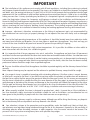
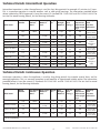
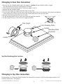
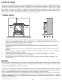
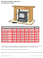
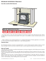
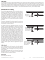
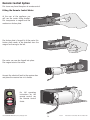
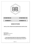
This Manual Must Always Be Available To The Stove Operator Installation Instructions Harmony evolution H13,H23,H33,H43 Stanford evolution S13,S23,S33,SP23,SP33 IN1115 Edition G8 July 2012 PART NUMBER This manual must be used in conjunction with document IN1173. The Wood and Mutlifuel Chimney and Installation Guide. Nestor Martin/Efel SERIAL NUMBER IMPORTANT . The installation of this appliance must comply with all local regulations, including those referring to national and European Standards before it can be operated. The stove is not suitable for a shared flue. However, for England and Wales, only, the coming into force on 1st April 2002 of SI 2002 No 440 exempts the householder from this legal requirement for the installation of solid fuel fired appliance whose rated heat output is 50kW or less in a building having no more than 3 storeys (excluding any basement) if a Competent Engineer is employed who is registered under the Registration Scheme for Companies and Engineers involved in the Installation and Maintenance of Domestic Solid Fuel Fired Equipment operated by HETAS Ltd. These registered Competent Engineers may also carry out associated building work necessary to ensure that the installed appliance complies with Building Regulations without involving the Local Authority Building Control Department. The installing engineer should refer to BS 8303: Code of practice for installation of domestic heating and cooking appliances burning solid mineral fuels. Improper adjustment, alteration, maintenance or the fitting of replacement parts not recommended by the manufacturer can cause injury or property damage. Do not operate the stove with faulty seals or damaged glass. Due to the high operating temperatures of this appliance it should be located away from pedestrian traffic and away from furniture and draperies. Do not store paper or wood near the appliance. Any mats and rugs put in front of the stove should be fire proof and secured to prevent the possibility of tripping. Advise all persons as to the stove’s high surface temperatures. If it is possible for children or infirm adults to come into contact with the stove, fit a suitable fire guard. It is imperative that all air passageways into, out of, and within the appliance are kept clean. All permanent ventilation into the room provided for the stove must remain clear and unobstructed at all times. Consideration must be given to the need for extra ventilation if another heating source needing air is to be operated simultaneously. If an extraction fan is proposed to be fitted to a connecting area of the house, after the stove has been installed, professional advice should be sought from a qualified engineer. The user should be advised that the appliance should be inspected regularly and the chimney cleaned at least annually. More frequent cleaning may be required and the advice of a qualified chimney sweep should be sought. Our range of stoves is capable of operating with outstanding efficiency if the flue system is correct. Because so little heat is wasted to the flue it is possible that moisture within the products of combustion will condense if the heat losses within the flue way are too great and allow the flue gases to cool. For this reason we recommend that the stove is fitted with a suitable flue liner, the same diameter as the flue spigot, to prevent the possibility of acidic damage to the fabric of the chimney and damage to the stove which will reduce the longevity of the stove. The flue pipe and chimney flue diameter must at no point be less than the diameter of the stove flue outlet. The installing engineer should refer to BS EN 15287-1:2007 design, installation and commissioning of chimneys. When correctly installed, the stove is designed to produce heat, safely. It cannot do so if the installation is less than absolutely stable, constructed of materials suitable for such an installation and consideration has not been given to the possibility of people with less than ideal common sense operating it. Have the existing chimney swept by a chimney sweep. Although you will be lining the chimney, any deposits left in the chimney will cause problems and may become a fire hazard. Your attention is drawn to the precautions and responsibilities under the Health and Safety at Work Acts, and whatever new legislation being introduced during the life of this document. Especially to the possibility of disturbing asbestos when disturbing structures in older properties. Also the caustic nature of fire cement. The personal risk of injury when moving heavy items with possible sharp edges. © EUROHEAT DISTRIBUTORS (H.B.S) LTD July 2012 2 E & OE Instructions Part number IN1115 Edition G7 The Model Range Explained Efel and Euroheat insist on progressive development to produce products which are market leading. Our aims are to produce stoves with the latest innovations, user friendly operation and highly efficient for lower cost operation. See data table for smoke control exempt and HETAS approved models. This manual offers installation information for the Evolution range of HARMONY H13, H23, H33, H43. STANFORD S13, S23, S33, SP23, SP33. In some cases you find references in this document to the model size rather than the models exterior design. There are four sizes of appliances, 13, 23, 33, 43. The 13 is the smallest and the 43 the largest. Although the exterior clothes change between model ranges, for example the Harmony 23 and the Stanford 23, the internal workings are the same. Exceptions: The SP models are fitted with a top hot plate for warming operations. Model Identification You will see on the front page of this document a label which confirms which model you have. This label also advises you of the stoves unique serial number. This information is also attached to your stove for reference. Important Please ensure the warranty registration form is completed if you are the installer and confirm with the user that it is there responsibility to return it to Euroheat. In this way the model and its history will be recorded for reference in the future. For the latest versions of manuals, technical information, accessories and spare parts visit the Euroheat web site. Stoves supplied through Euroheat authorized retailers. For England, Wales, Scotland and Northern Ireland Euroheat Distributors (H.B.S). Ltd. Unit 2, Court Farm Business Park, [email protected] Bishops Frome, Worcestershire. WR6 5AY. Whilst Euroheat are always happy to assist, please ensure you have read this manual and the chimney and installation guide IN1173. First contact your supplying retailer for assistance. If you find this not successful contact the Euroheat Technical support team. Technical support telephone Number 01885 491117. E-mail [email protected]. www.euroheat.co.uk Before telephoning ensure you have the stoves serial number to hand and that you are a Registered Competent Engineer. If you are not a registered engineer seek one for assistance. A list of engineers can be obtained from HETAS. Euroheat unfortunately are not able to offer support for appliances which where not supplied by Euroheat. Stoves supplied through Eireheat authorized retailers. www.eireheat.com For Eire Sean Murphy Heating Ltd Kinvara Co Galway Eire [email protected] (091)637701 Fax: (091)637797 International +353 91637701 For support for appliances supplied through Eireheat in Ireland please contact using the details listed above. Thermic Distribution Europe Sa 11 Rue De Lion B-5660 Frasnes Les Couvin, Belgium. © EUROHEAT DISTRIBUTORS (H.B.S) LTD. July 201s www.nestormartin.com 3 E & OE Instructions Part number IN1115 Edition G8 Technical Details Intermittent Operation Intermittent operation is when the appliance is used for short firing periods for example 45 minutes to 2 hours. This is a common operation in warmer weather such as cold spring evenings. The information provided below where indicated as HETAS approved is from the current CE standards EN 13240:2001 and EN 13240 A2:2004. The test fuel for wood burning, Beech, for Coal burning Anthracite. Model Number Model Name Harmony 13 Wood Harmony 13 Coal Heat Output Heat Output Weight Nominal Nominal KG Wood Coal* H13* Flue Gas Flue Gas Mass Temperature Flow g/s Down Stream of Flue Spigot deg C Efficiency with Top Flue Connection 96 12pa 4.9 350 77.1% Net 70.2% Gross 3.5kW 96 12pa 3.8 210 82.8% Net 75.4% Gross 5.0kW H13* Flue Draught Nominal Harmony 23 H23* 7.7kW 7.7kW 124 12pa 7.7 326 Harmony 33 H33** 9.2kW 9.2kW 143 12pa 6.5 305 Harmony 43 H43* 10.5 10.5kW 186 12pa 6.5 357 S13* 5.0kW 96 12pa 4.9 350 77.1% Net 70.2% Gross 3.5kW 96 12pa 3.8 210 82.8% Net 75.4% Gross Stanford 13 Wood Stanford 13 Coal Stanford 23 Stanford SP23 HP Stanford 33 Stanford SP33 HP S13* S23* 7.7kW 7.7kW 124 12pa 7.7 326 SP23 HP* 7.7kW 7.7kW 132 12pa 7.7 326 S33** 9.2Kw 9.2kW 146 12pa 6.5 305 SP33 HP** 9.2kW 9.2kW 153 12pa 6.5 305 See smoke control exempted table See smoke control exempted table * HETAS Approved ** Awaiting HETAS Approval Technical Details Continuous Operation Continuous operation is when the appliance is used for long firing periods for example several hours and for overnight operation. This is a common operation in cold weather as experienced in deep winter. The information provided below is from the current CE standards EN 13240:2001 and EN 13240 A2:2004. The test fuel for wood burning, Beech, for Coal burning Anthracite. Model Number Model Name Harmony 13 Wood* Harmony 13 Coal* Stanford 13 Wood* Stanford 13 Coal* Heat Output Heat Output Weight Nominal Nominal KG Wood Coal* H13 5.4kW H13 S13 S13 3.5kW 5.4kW 3.5kW Flue Draught Nominal Flue Gas Flue Gas Mass Temperature Flow g/s Down Stream of Flue Spigot deg C Efficiency with Top Flue Connection 96 12pa 4.9 350 83.4% Net 75.9% Gross 96 12pa 3.8 210 78.3% Net 71.2% Gross 96 12pa 4.9 350 83.4% Net 75.9% Gross 96 12pa 3.8 210 78.3% Net 71.2% Gross * HETAS Approved © EUROHEAT DISTRIBUTORS (H.B.S) LTD July 2012 4 E & OE Instructions Part number IN1115 Edition G7 Smoke Control Exempted Models listed as smoke control exempted have passed the very strict U.K. requirements and can operate in smoke control zones burning dry seasoned wood. Harmony 23 * Free Air * Free Air UK Smoke Requirement Requirement Control Equivalent Area Equivalent Area Flue Size Exemption as Approved as Approved Burning Document J Document J Wood >5.0m³/(h.m²) <5.0m³/(h.m²) 5” (125mm) Nil* 2750mm2 Approved 2 2 6” (153mm) 1485mm 4235mm Approved Harmony 33 6” (153mm) 2310mm2 Harmony 43 7” (180mm) 3025mm2 Stanford 13 5” (125mm) Nil* Stanford 23 6” (153mm) Stanford SP23 HP Model Harmony 13 Efficiency Efficiency Efficiency Net % Net % Gross % Rear flue Top flue Rear flue Efficiency Gross % Top flue See intermittent or continuous operation 78# 72.8# 78 72.8 80# 72.8# 5060mm2 5775mm2 Approved Approved 1485mm2 2750mm2 4235mm2 Approved See intermittent or continuous operation 78# 72.8# 6” (153mm) 1485mm2 4235mm2 Approved 78# 72.8# Stanford 33 6” (153mm) 2310mm2 5060mm2 Approved 78 72.8 Stanford SP33 HP 6” (153mm) 2310mm2 5060mm2 Approved 78 72.8 Models indicated above as HETAS approved to a certain flue position are indicated by # * Free Air Requirement Air requirement equivalent area. Building regulations Document J, advises that an air supply,permanently open vents, should be installed for appliances: If design air permeability >5.0m³/(h.m²) then 550mm²/kW of appliance rated output above 5kW or _ If design air permeability <5.0m³/(h.m²) then 550mm²/kW of appliance rated output Equivalent air is as measured according to the method in BS EN13141-1:2004 It is unlikely that a dwelling constructed prior to 2008 will have an air permeability of <5.0m³/(h.m²) at 50pa unless extensive measures have been taken to improve air-tightness. Carbon Monoxide Alarms Where a new solid fuel stove is installed in a property a carbon monoxide alarm should be located in the same room where the appliance is located: a. on the ceiling at least 300mm from any wall or, if it is located on a wall, as high up as possible (above any doors and windows) but not within 150mm of the ceiling; and b. between 1m am 3m horizontally from the appliance. Carbon monoxide alarms should comply with BS EN 50291:2001 and be powered by a battery designed to operate for the working life of the alarm. The alarm should incorporate a warning device to alert users when the working life of the alarm is due to end. Mains-powered BS EN 50291 Type A carbon monoxide alarms with fixed wiring (not plug in types) may be used as alternative applications provided they are fitted with a sensor failure warning device. © EUROHEAT DISTRIBUTORS (H.B.S) LTD. July 201s 5 E & OE Instructions Part number IN1115 Edition G8 Useful Organisations UK Solid Fuel Association 0845 601 4406 www.solidfuel.co.uk The National Association of Chimney Sweeps 01785 811732 www.chimneyworks.co.uk HETAS Ltd.0845 634 5626www.hetas.co.uk Stoves Construction The plexus control is the centre of the air inlet system. The fuel select lever, controls the direction of air flow, either air wash or under grate. The burning rate control governs the amount of air entering the fire. Pre Heated Primary Air Rear Flue Option Top Flue Option Top Chamber Baffle Grate Remote Control Motor Internal Cast Iron Protection Plates Fuel Guard Plexus Control Assembly Ash Pan Door Riddling Actuating Rod Air Volume Control © EUROHEAT DISTRIBUTORS (H.B.S) LTD July 2012 Air Direction lever 6 E & OE Instructions Part number IN1115 Edition G7 Harmony 13, Stanford 13: Correct Position of the Flue Baffle Plate in the Flue Baffle The flue baffle is fixed to the top of the stove below the flue outlet. Lift the flue baffle plate up to the flue baffle. The wing towards the back of the stove and with it angled downwards. The lugs on the flue baffle plate should be located in the cut out on the base of the flue baffle. Once the lugs have been located into the cut out on the base of the flue baffle slide it towards the back of the stove until it is fully pushed in. The baffle plate is in the correct position when the small upturn on the baffle plate is against the facing wall of the flue baffle. © EUROHEAT DISTRIBUTORS (H.B.S) LTD. July 201s 7 E & OE Instructions Part number IN1115 Edition G8 Harmony and Stanford 13: Top Flue Connection Spigot Protector When using top flue outlet the flue spigot should be fitted with the flue spigot protector collar. This protection collar prevents damage to the top flue outlet. The flue spigot and flue baffle plate (see page 8) may have been fitted in the factory and in transit the flue baffle plate may have moved, so you MUST ensure that it is located correctly within the flue baffle. If the flue spigot is fitted to the pallet on which the stove is transported, the spigot protector collar will be found within the stove. You MUST ensure that these are correctly fitted, see below, when the top flue option is used. The spigot protector collar is not required if the stove is to be a rear exit flue. It is imperative that the flue baffle plate is fitted correctly (see page 7), so that once the stove is installed, the flue baffle plate may be slid out of the stove to gain access to the flue way for cleaning and maintenance. Flue spigot Spigot protector collar Gasket Spigot protector collar Do not fit flue spigot protector collar for rear outlet option. Flue Outlet Configuration: all other models Top Flue Connection When using top flue outlet the flue spigot with certain models is fitted with a flue spigot protector. This protection tube prevents damage to the flue outlet and slows down the movement of flue gases to the flue system. See table below for model information. Protector baffle plate Spigot protector Flue Spigot Gasket Front of stove Rear of stove Spigot protector collar Correct configuration of spigot protector and protector baffle plate. Model Spigot Protector Harmony 13 Yes Harmony 23 Yes Harmony 33 Yes Harmony 43 Yes (only enamel models) Stanford 13 Yes Stanford 23 Yes Stanford SP23 No Stanford 33 Yes Stanford SP33 No Do not fit flue spigot protector collar for rear outlet option. © EUROHEAT DISTRIBUTORS (H.B.S) LTD July 2012 8 E & OE Instructions Part number IN1115 Edition G7 Changing to Rear Flue Connection 1. Remove the top chamber baffle plate (see page 6). Caution the top chamber baffle is fragile. See operating instructions for information on removal. 2. Then remove protector baffle plate if fitted (see pages 7 and 8). 3. Replace the top chamber baffle. 4. Remove flue spigot and spigot protection from top of stove. 5. Some models will require the rear heat shield rear flue access plate to be removed. With a hack saw blade or similar remove the section from the rear heat shield which covers the rear flue outlet. 6. Remove flue blanking plate from rear of stove. Spigot protector collar 7. Fit the blanking plate to top of stove with the blanking plate protector. 8. Fit flue spigot to rear of stove (do not fit spigot protector). Flue Spigot Flue Blanking Plate Gasket Blanking Plate Protector Gasket Top flue blanking plate location. Changing to Top Flue Connection The procedure is as fitting rear flue but follow the information in reverse and fit the flue spigot protector and protector baffle plate. (See page 8) © EUROHEAT DISTRIBUTORS (H.B.S) LTD. July 201s 9 E & OE Instructions Part number IN1115 Edition G8 Fireplace Design Do not be tempted to fit the stove into an unsuitable fireplace. Beyond the requirements of Building Regulations and access to facilitate servicing the stove, providing a setting which will compliment a stove is not a luxury, it is the practicality of making the most of an investment. A good builder or fireplace specialist will be able to transform even the most utilitarian of fireplaces. Whether altering its proportions to those of the “Golden Mean” ideal, see below, or exposing a wooden or stone lintel or simply removing superfluous detailing for a comparatively small cost, and the result will be a pleasure for many years. “Golden Mean” 1 2/3 2/3 1/3 2/3 1. The stove must always stand perfectly level. Adjustment screws and/or triangular plastic levelling spacers may be provided with the stove. The provision of a suitable level hearth within the recess is an important consideration when planning a fireplace. 2. Sufficient space should be allowed for service work. 3. At least the minimum clearance from inflammable materials and conforming to the current Building Regulations. 4. Sufficient space around the stove so that the controls may be operated without the risk of injury to the operator. 5. Mounting brackets should be installed to facilitate the secure fitting of a fire guard, if one is to be fitted to protect the young, elderly or infirm. 6. Curtains and soft furnishings should be a minimum of 1m from the stoves body or the surface temperature of these furnishings must not exceed 65°C. 7. The mounting of expensive paintings, mirrors and plasma screen televisions above a fireplace is not recommended. Hearths The stove should stand wholly above a hearth constructed of suitably robust materials and should be able to accommodate the weight of the appliance and its unsupported flue components. The materials should conform to local Building Regulations and British Standards. If the stove is not to stand in a purpose built fireplace recess (this excludes prefabricated constructions) a hearth made of non-combustible board, steel material, tiles or glass of at least 12mm thick may be used as long as the floor can accommodate the weight of the appliance and its unsupported flue components. All our multifuel stoves conform to standards where the hearth temperature does not exceed 100°C. This means a hearth of only 12mm of non combustible material can used. This information only applies to our range of appliances. Caution do not fit a 12mm hearth to other manufactures products unless documentation is provided to prove hearth temperatures. © EUROHEAT DISTRIBUTORS (H.B.S) LTD July 2012 10 E & OE Instructions Part number IN1115 Edition G7 Minimum Installation Clearances From Combustible Materials. A B E D F C Minimum clearances from combustible materials Model Harmony 13 Wood Harmony 13 Multifuel Harmony 23 Wood Harmony 33 Wood Harmony 43 Wood Stanford 13 Wood Stanford 13 Multifuel Stanford 23 Wood Stanford SP23 Wood Stanford 33 Wood Stanford SP33 Wood A 300mm 300mm 300mm 300mm 300mm 300mm 300mm 300mm 300mm 300mm 300mm B 150mm 150mm 250mm 250mm 250mm 150mm 150mm 250mm 250mm 250mm 250mm C 300mm 300mm 300mm 300mm 300mm 300mm 300mm 300mm 300mm 300mm 300mm D 200mm 200mm 300mm 300mm 300mm 200mm 200mm 300mm 300mm 300mm 300mm E 150mm 150mm 250mm 250mm 250mm 150mm 150mm 250mm 250mm 250mm 250mm F* 12mm 12mm 12mm 12mm 12mm 12mm 12mm 12mm 12mm 12mm 12mm * When installed as a free standing appliance or in a prefabricated fireplace. All other applications must conform to current constructional fireplace requirements per Building regulations with a constructional hearth. In all installations surrounding flammable materials must not exceed 65°C. Curtains and furnishings should be a minimum of 1m from the stove or the surface temperature must not exceed 65°C. © EUROHEAT DISTRIBUTORS (H.B.S) LTD. July 201s 11 E & OE Instructions Part number IN1115 Edition G8 Minimum Installation Clearances From Non-combustible Materials. A B E D F C From Non-combustable materials A 100mm B 75mm C 300mm D 50mm E* 75mm F** 12mm * If a remote control is to be used with the appliance, the distance E requires to be increased to at least 100mm to allow access to the remote control receiver. If this space is not available a remote mounted receiver can be installed. ** When installed as a free standing appliance or in a prefabricated fireplace. All other applications must conform to current constructional fireplace requirements as per Building regulations. General advice Not all fireplace apertures are square or rectangular box`s. In cases of where apertures tapper or there is an arch top for example a careful assessment should be made to confirm operational clearances can be achieved. Rules of Thumb If the clearances at the sides are small but the clearances at the top are large this will still allow access to remove remote control motor if fitted. Heat likes to rise, allow as much space as possible above the appliance for heat to escape into the room. If there is only a small aperture above the stove bring the stove out into the room by at least 2/3 to assist with the heat distribution. Always consider that the stove is a heating appliance and would distribute its heat best when free standing. So allow as much space around the stove as possible even if it requires removal of fireplace surround material to create an ideal opening. (Expert building advice may be required). © EUROHEAT DISTRIBUTORS (H.B.S) LTD July 2012 12 E & OE Instructions Part number IN1115 Edition G7 The Flue It is possible to remove the top chamber baffle to access the flue for cleaning. However we would advise that if at all possible an external cleaning access is provided. If the chimney has been lined with the same size flue as the flue pipe it will be possible to sweep from the flue access point. If the flue is of a larger size than the flue pipe it may not be possible to use a sweeping brush of adequate size. In which case another cleaning access will be required. For detailed information see IN1173 The Wood and Mutlifuel Chimney and Installation Guide. Minimum Air Setting The air shutter governing the air to the air wash system is divided into two flaps. The larger flap is controlled directly by the operation of the cam and air volume control. The smaller flap is operated by an adjustable screw fitted to the larger flap. This allows the smaller flap to follow the movements of the larger flap as it opens and closes but by adjusting the screw it is possible to set a minimum closing position of the smaller flap to provide a constant air bleed. Minimum air adjusting screw The screw is adjusted at the factory to give the maximum air bleed setting. This setting under normal chimney and fuel conditions should be correct. This facility of having an adjustable minimum air setting provides a positive repeatable air setting that will give the lowest burning rate at which the stove will continue burning when the firing rate control is turned to its minimum position. It will also give a small feed to the air wash when the stove is burning coal, not enough to risk damage to the grate, but enough to help keep the glass clean. It is also an important safety feature. If the stove has been burning with a constant air supply it has been generating and burning the volatile gases from the fuel. If the air supply is abruptly and completely removed the fire will extinguish but the release of gases will continue for some time. These gases will be above their ignition temperature and be potentially explosive if they come into contact with air. The constant air bleed that the small flap allows will keep some of these gases burning and prevent sudden ignition whilst the generation of gases reduces. Adjustment Screw adjusted to give a supply of air when control set to minimum Small flap opens and closes as rotation of the cam operates the large flap If it is found that the fire burns for only short periods while set to the “0” position it will be most likely that the flue draught is high. Commonly found in tall or excessive sized chimneys. To extend the burning cycle the minimum flap can be adjusted to allow less air to enter at low settings. Adjust the flap to give your required settings. Important Do not fully close the flap. © EUROHEAT DISTRIBUTORS (H.B.S) LTD. July 201s 13 E & OE Instructions Part number IN1115 Edition G8 Remote Control Option This stove may have the option of remote control. Fitting the Remote Control Motor At the rear of the appliance you will see the motor fitting bracket. This incorporates a magnet and the mechanism friction plate. The friction plate is hinged. To fit the motor this friction plate needs to be detached from the magnet and swung to the left. The motor can now be slipped into place. The magnet retains the motor. Connect the electrical lead to the receiver box and place the receiver box in its holder. For full operating instructions for the remote control see the Remote Control Guide. © EUROHEAT DISTRIBUTORS (H.B.S) LTD July 2012 14 E & OE Instructions Part number IN1115 Edition G7 Commissioning Check List Mark box when completed X Inspect the door and glass seals and ensure all handle latches are adjusted correctly, procedure in the operating instructions. Check baffle is installed correctly and that the riddling mechanism is operating. Ensure that the fire responds to the operation of the controls and that there are no visible emissions of the combustion products into the room. Instruct the user on the use of the tools, operation of the appliance and the summer shut down procedure. Information in the operating instructions. Instruct the user never to operate the stove with the furnace door open and that the user is aware of the requirement of a suitable fire guard where children, the old or infirm may come into contact with the appliance. Hand over the installation instructions, operating instructions and completed warranty form to the user. Remind the owner to return the warranty form for registration. Complete the Stoves Registration Form and Pass to User for Registration Euroheat and Efel have a policy of continual research and development and reserve the right to modify its appliances without prior notice. We make every effort to ensure that the information provided in this document is correct and accurate at the time of printing. Continued updates occur to adapt documents to customer requirements and appliance changes. For the latest editions of all Euroheat documentation visit our web site www.euroheat.co.uk. We would request that you inform Euroheat of information which you feel is not provided in this document which would assist other users in the future. The Euroheat Technical Team Welcome to the World of Real Stoves Euroheat Technical Team © EUROHEAT DISTRIBUTORS (H.B.S) LTD. July 201s 15 E & OE Instructions Part number IN1115 Edition G8 Need more info? with over 10,000 pages of technical information, spare parts, product shots, news and 1001 other things, - you will not find a more comprehensive solution to your queries, whatever time of the day. www.euroheat.co.uk Court Farm Business Park, Bishops Frome, Worcestershire WR6 5AY Technical: Reception: 01885 491117 01885 491100