1
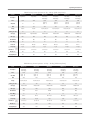
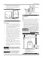
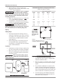
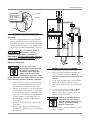
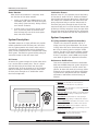
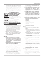
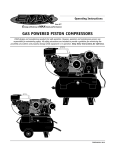
Operating Instructions
ROTARY SCREW COMPRESSORS
EMAX designs and manufactures products for safe operation. However, operators and maintenance persons are
responsible for maintaining safety. All safety precautions are included to provide a guideline for minimizing the
possibility of accidents and property damage while equipment is in operation. Keep these instructions for reference.
Fully packaged unit with air dryer (vertical tank)
Base mount
Rotary Screw Compressor
Base mount unit with vertical auxillary air storage tank
Fully packaged unit with air dryer (horizontal tank)
EMNR000001 1110
EMAX Rotary Screw Compressors
Contents
Page No.
Lubrication Process . . . . . . . . . . . . . . . . . 8
Variable Speed Drive Information . . . . . . . . . 2
Model Specification Charts . . . . . . . . . . . . . 2-3
System Components . . . . . . . . . . . . . . . . . . . 8
Safety Information . . . . . . . . . . . . . . . . . . . 4
PLC (Programmable Logisitical Control) . . . . 8
Tag Definitions . . . . . . . . . . . . . . . . . . . . 4
Mechanical Components . . . . . . . . . . . . 9-11
Basic Guidelines . . . . . . . . . . . . . . . . . . . . 4
Operation . . . . . . . . . . . . . . . . . . . . . . . . . 12
Breathable Air . . . . . . . . . . . . . . . . . . . . 4
Safety Rules . . . . . . . . . . . . . . . . . . . . . 12
Pressurized Components . . . . . . . . . . . . . . 4
Initial Checks . . . . . . . . . . . . . . . . . . . . 12
Personal Protective Equipment . . . . . . . . . . 4
Start Up . . . . . . . . . . . . . . . . . . . . . . . . 13
Inspection . . . . . . . . . . . . . . . . . . . . . . . . . 4
Storage . . . . . . . . . . . . . . . . . . . . . . . . 13
Forklift Safety . . . . . . . . . . . . . . . . . . . . . 4
Lifting Safety . . . . . . . . . . . . . . . . . . . . . . 5
Maintenance . . . . . . . . . . . . . . . . . . . . . . . 14
Restarting Procedure . . . . . . . . . . . . . . . 13
Installation . . . . . . . . . . . . . . . . . . . . . . . . . 5
Safety Steps . . . . . . . . . . . . . . . . . . . . . 14
Area . . . . . . . . . . . . . . . . . . . . . . . . . . . 5
Lubricating Oil . . . . . . . . . . . . . . . . . . . 14
Piping . . . . . . . . . . . . . . . . . . . . . . . . . . 6
Belt . . . . . . . . . . . . . . . . . . . . . . . . . . 15
Safety Steps . . . . . . . . . . . . . . . . . . . . . . 6
System Pressure . . . . . . . . . . . . . . . . . . 15
Installing . . . . . . . . . . . . . . . . . . . . . . . . 6
Safety Valve . . . . . . . . . . . . . . . . . . . . . 15
Oil Check . . . . . . . . . . . . . . . . . . . . . . . . 6
Air/Oil Separator Filter . . . . . . . . . . . . . . 15
Electrical Installation . . . . . . . . . . . . . . . . 7
Maintenance Schedule . . . . . . . . . . . . . . . . 16
Motor Rotation . . . . . . . . . . . . . . . . . . . . 8
Troubleshooting . . . . . . . . . . . . . . . . . . 17-19
System Description . . . . . . . . . . . . . . . . . . . 8
Warranty . . . . . . . . . . . . . . . . . . . . . . . . . . 20
Air Process . . . . . . . . . . . . . . . . . . . . . . . 8
To convert to Varible speed drive,
contact EMAX customer service for
more information. 1-866-294-4153.
Be sure to install VSD in a clean, dust-free
environment.
Variable Speed Drive
The variable speed drive is an auxillary feature available on all EMAX compressors. A variable speed drive
or VSD will save energy consumption and wear on the
electric motor. The VSD regulates amp draw during
start-up and motor speed during operation according
to air demand.
VSD Device
All EMAX compressors are equipped with a VSD compliant motor, ventilated electrical box and adequate
space in compressor cabinet for easy installation.
The electronic controller (PLC) for the compressor
unit, has a 4-20 milliamp control signal built-in to
control VSD speed reference. The PLC can provide
start/stop command and display any fault codes for
the VSD device.
Dedicated Cooling Fan
Wiring access area
Each compressor cabinet has built-in VSD compartment
2
Operating Instructions
EMAX Rotary Screw Systems: 5 Hp - 20 Hp (VSD Compliant)
Model No.
ERS0070001ERS0100001ERS0070003ERS0100003 ERS0150003ERS0200003
Single Phase Single Phase
Description
Motor
Three Phase
Dual Voltage
10HP 15HP 230V: 18
Amp Draw
3240
460V: 9
230V: 24
460V: 12
230V: 36
460V: 18
10HP Three Phase
Dual Voltage
7.5HP 7.5HP Three Phase
Dual Voltage
Three Phase
Dual Voltage
20HP
230V: 48
460V: 24
RPM
1750175017501750 17501750
Voltage
208/230
208/230
208/230/460/575208/230/460/575 208/230/460/575208/230/460/575
SCFM @ 100 PSI
29452945 6285
Start Type
Drive Type
BeltBeltBeltBelt BeltBelt
Air End Model
B40B40B40B40 B60B60
Noise DB(a)
62646264 6769
Outlet Size
NPT 3/4”
NPT 3/4”
NPT 3/4”
NPT 3/4”
NPT 1”
NPT 1”
Oil Capacity
1 gal.
1 gal.
1 gal.
1 gal.
2.5 gal.
2.5 gal.
33 x 24 x 42
33 x 24 x 42
33 x 24 x 43
34 x 24 x 43
36 x 31 x 49
36 x 31 x 49
Dimensions
L•W•H
(inches)
Magnetic Starter
Magnetic Starter
Y-Delta & VSD
Y-Delta & VSD
Y-Delta & VSD
Y-Delta & VSD
Weight (lbs.)
88093088093012101260
Shipping Weight
92898692898612701330
EMAX Rotary Screw Systems: 25 Hp - 60 Hp (VSD Compliant)
Model
ERS0250003ERS0300003ERS0400003 ERS0500003ERS0600003
Description
Motor
Three Phase Dual Voltage
25 HP Three Phase
Dual Voltage
Three Phase
Dual Voltage
30 HP 40 HP Three Phase
Dual Voltage
50 HP Three Phase
Dual Voltage
60 HP
230V:60
230V:72
230V: 96
230V:120
230V: 144
Amp Draw
460V:
30460V:
36460V:
48 460V:
60460V:
72
RPM1750
Voltage
1750
1750
1750
1750
208/230/460/575208/230/460/575 208/230/460/575 208/230/460/575208/230/460/575
SCFM @ 100 PSI108
Start Type
Drive TypeBelt
Y-Delta & VSD
129
188
Y-Delta & VSD
Y-Delta & VSD
Belt
Belt
235
Y-Delta & VSD
261
Y-Delta & VSD
Belt
Belt
B170
Air End ModelB101
B101
CA116D
B170
Noise DB(a)73
75
79
79
Outlet Size
NPT 1”
NPT 1”
NPT 1-1/4”
NPT 1-1/4”
NPT 1-1/4”
Oil Capacity
2.5 gal.
2.5 gal.
3 gal.
4 gal.
4 gal.
43 x 38 x 57
43 x 38 x 57
48 x 44 x 61
53 x 50 x 65
53 x 50 x 65
Dimensions
L•W•H
(inches)
Weight (lbs.)1440
Shipping Weight
1540
1910
2420
81
2860
15001600 1970 24902928
3
EMAX Rotary Screw Compressors
Safety
Breathable Air
This manual contains very important information to
know and understand. This is provided for SAFETY
and to PREVENT EQUIPMENT PROBLEMS. To help understand this information, observe the following:
Danger indicates an imminently
hazardous situation which, if not
avoided, will result in death or serious injury.
Warning indicates a potentially
hazardous situation which, if not
avoided, could result in death or serious injury.
Caution indicates a potentially
hazardous situation which, if not
avoided, may result in minor or moderate injury.
Notice indicates important information, that if not followed, may
cause damage to equipment.
MANUAL
This equipment is supplied with a ASME designed
pressure vessel protected by an ASME rated relief
valve. Pull the ring before each use to make sure
the valve is functional. Refer to figure 10. DO
NOT attempt to open valve while the machine is
under pressure.
Read all manuals included with this
product carefully. Be thoroughly
familiar with the controls and the
proper use of the equipment.
Personal Protective Equipment
Be sure all operators and others around the
compressor and its controls comply with all applicable OSHA, Federal, State and Local regulations,
codes and standards relating to personal protective equipment. This includes respiratory protective equipment, protection for the extremities,
protective clothing, protective shields and barriers, electrical protective equipment, and personal
hearing protective equipment.
CALIFORNIA PROPOSITION 65
This product or its power cord may
contain chemicals known to the
State of California to cause cancer and birth defects or
other reproductive harm. Wash hands after handling.
1. Allow only trained, authorized persons who
have read and understood these operating
instructions to use this compressor. Failure
to follow the instructions, procedures and
safety precautions in this manual can result
in accidents and injuries.
2. NEVER start or operate the compressor under
unsafe conditions. Tag the compressor,
disconnect and lock out all power to it to
prevent accidental start-up until the condition is corrected.
3. Install, use and operate the compressor only
in full compliance with all pertinent OSHA
regulations and all applicable Federal, State
& Local Codes, standards and regulations.
4. NEVER modify the compressor and/or controls
in any way.
5. Keep a first aid kit in a convenient place.
Seek medical assistance promptly in case
of injury. Avoid infection by caring for any
small cuts and burns promptly.
2. DO NOT use air line anti-icer systems in air
lines supplying respirators or other equipment used to produce breathable air. DO NOT
discharge air from these systems in unventilated or other confined areas.
Pressurized Components
Basic Guidelines
1. NEVER use air from this compressor for
breathable air except in full compliance with
OSHA Standards 29 CFR 1910 and any other
Federal, State or Local codes or regulations.
Death or serious injury can result
from inhaling compressed air
without using proper safety
equipment. See OSHA standards
on safety equipment.
Inspection
Inspect compressor prior to any use. Check for external damage that might have occurred during transit.
Make sure pallet-mounted
compressors are firmly secured to
the pallet before moving. NEVER attempt to move
a compressor that is not secure as serious injury or
property damage could occur.
A forklift may be necessary for unloading the EMAX
compressor. Use all forklift safety measures and
require a certified forklift operator. Refer to figure 1
for safe unloading procedure.
Forklift Safety
4
1. Make sure lift operator stays aware while
moving compressor.
2. Be sure load is secure and well balanced
before moving the compressor.
Operating Instructions
3. Make sure forks are fully engaged and tipped
back before lifting or moving compressor.
4. Keep load as low as possible and observe
safe operating practices.
Mounting Base
Compressor Enclosure
Shipping Bracket
(Remove 4)
Figure 2: Remove Shipping Brackets
Installation
Area
Exhaust air from this unit can be used to supplement environment heat. Install unit in separate room
then create duct system as shown in figure 3.
1. Install compressor in a clean, well ventilated
and well lit area. Make sure air inlet is away from
exhaust fumes or other toxic, noxious or corrosive fumes or substances. Installation area must
maintain low relative humidity and a temperature
range between 35˚ - 110˚ F. This unit must be
kept under roof and away from rain, snow, etc.
Lumber
Figure 1: Use Lumber to Protect Compressor
Lifting Safety
1. Carefully inspect all lifting equipment and make
sure it is in good condition. Rated capacity should
exceed compressor weight. Make sure lifting hook
has a functional safety latch or equivalent and is
properly attached to lifting feature.
2. Make sure lifting points are in good condition and
tighten any loose nuts or bolts before lifting.
3. Use provided lifting feature or appropriate sling. A
sling must be used when moving compressor with a
helicopter or other air-borne equipment. Be sure to
follow OSHA standards 29 CFR 1910 Subpart N.
4. Use guide ropes or equivalent to prevent twisting
or swinging of the compressor while it is in the
air and NEVER attempt to lift in high winds. Keep
compressor as low to the ground as possible.
5. Keep persons away and make sure no one is under
the compressor while it is lifted.
6. Only use lifting features provided for entire compressor package. NEVER use bolts or other hooks on
invididual components to move the compressor.
7. Make sure to put compressor on a level surface that
can support the weight of the compressor and loading equipment.
In environments where fine dust
is common, such as granite or
concrete plants, it is imperative the installation of
this compressor is in a separate area with
dedicated ventilation. Failure to provide dust free
operating area will void the warranty.
Vent To Shop
(Open/Close)
Vent To Outside
(Open/Close)
Rotary Screw
Compressor
Cabinet
Fresh Air
Inlet
(Keep
Open)
Do not operate unit if damaged
during shipping, handling or use.
Damage may result in bursting and cause injury or
property damage.
For Cold Weather Use:
Open shop vent and close outside vent to
use exhaust heat from compressor.
Remove shipping brackets from
each corner of mounting base
before operating compressor. Refer to figure 2.
For Warm Weather Operation:
Close shop vent and open outside vent to
divert exhaust heat outdoors.
Figure 3: Utilize Exhaust Heat
5
EMAX Rotary Screw Compressors
2. Allow at least 24 inches of clear space
around the sides and back and at least 3 feet
in front of the compressor.
This compressor unit is equipped
with internal rubber vibration
isolators. To avoid internal pump damage, DO NOT
use an additional rubber mounting surface when
installing compressor.
Minimum Pipe Size For Compressed Air Lines
(Pipe size shown in inches)
3. Make sure compressor base is on a hard, flat
surface and anchored securely.
4. If installation is above the first story of a
building, use appropriate vibration insulation.
Tank Sizing Guideline: Tank
capacity must be at least 1.2
gallons for every CFM of air produced by compressor.
This will minimize wear on internal pump parts.
250 ft.
3/4
1
40
3/4
1
1
1
60
3/4
1
1
1
100
1
1
1
1-1/4
125
1-1/4
1-1/4
1-1/2
1-1/2
150
1-1/2
2
2
2
200
2
2
2
2
Air Drop
(typ.)
Air Drop:
Install tee fitting with branch to top
to minimize condensation in air drop
2. Flow-limiting valves are listed by pipe size
and rated CFM. Select appropriate valves
accordingly, in accordance with the manufacturer’s recommendations.
From Compressor
ELEVATION
Installing
100 ft.
3/4
Install tee fitting
in piping from air
supply to minimize
pressure drop and to
allow airflow in two
directions.
1. Install appropriate flow-limiting valves as
necessary according to pipe size(s) used and
run lengths. This will reduce pressure in case
of hose failure, per OSHA Standard 29 CFR
1926.302(b)(7).
50 ft.
3/4
PLAN VIEW
Closed loop system
Safety Steps
25 ft.
20
Piping
Length Of Piping System
SCFM
1. Install piping as shown in Figure 4. Refer to figure 5 for recommended closed loop installation.
Water trap
with drain
2. Make sure any tube, pipe or hose connected to
the unit can withstand operating temperatures
and retain pressure.
Never use plastic (PVC) pipe for
compressed air. Serious injury or
death could result.
Ball Valve
Ball
Valve
From
Compressor
Figure 5: Closed Loop Installation
To Shop
Piping
Air
Storage
Tank
Rotary Screw
Compressor
Cabinet
3. Install appropriate ASME code safety valves
and make sure piping system is equipped with
adequate condensate drains.
4. Never use reducers in discharge piping. Keep all
piping and fittings the same size in the piping
system.
5. For permanent installations of compressed air
systems, determine total length of system and
select correct pipe size. Make sure underground
lines are buried below frost line and avoid areas
where condensation could build up and freeze.
6. Test entire piping system before underground
lines are buried. Be sure to find and repair all
leaks before using compressor.
Air Dryer
Water Drain Valve
To Air Tool
Coalescing Filter
with Auto Drain
Figure 4: Basic Piping Diagram
6
Operating Instructions
Oil level must be
maintained between
the two red lines
during operation and
while loaded
Air/Oil Tank
QF
Sight Glass
L1 L2 L3
TB
L1 L2 L3
TB1
PE
E COM AI2
L1 L2 L3
R S T
CT1
A1
Figure 6: Sight Glass for Lubricating Oil
+24V
LI1
RIA RIC
40
37
22 14
Inverter
Run
Inverter
Fault
a
b
c
o
U V W
CT2
a
b
c
o
B C
B C
Oil Check
This unit is shipped with oil in it and should be
ready to operate. Be sure to check for proper oil
level before operating the compressor. Compressor
must be off at least 45 min. - 1 hr. before checking to ensure accurate reading. Refer to figure 6.
KM2
KM5
KM1
KM4
KM3
Use only EMAX oil, model no.
AROL8000G1. For food
manufacturing applications, use model no.
AROLFOODG1. Use of any other product will cause
product damage and void the warranty. Refer to
warranty statement for oil requirements.
TB3
TB4
(Notice 2)
(Notice 2)
M
M1
Electrical Installation
3
PE
Main Motor
Be sure only trained and
authorized personnel install and
maintain this compressor in
accordance with all applicable
federal, state and local codes,
standards and regulations. Follow
all NEC (National Electric Code) standards especially
those concerning equipment grounding conductors.
M
M2
3
Fan Motor
Figure 7: Wiring Diagram
5. Refer to amp load information on motor tag
and use correctly sized wiring. Be sure to
consider distance between power supply and
machine.
1.
Follow all NEC and local codes for electrical wiring.
Allow only authorized EMAX service person or certified electrician to install electrical components.
6. Install surge protection device between power
supply and compressor electrical cabinet.
7. Make sure to install properly sized breakers and
fuses.
8. The unit must be properly grounded. DO NOT
connect ground wire to air or cooling lines.
Connect ground wire to grounding lug in the
compressor electrical cabinet.
2. Put unit on dedicated circuit and make sure
no other electrical equipment is wired into
it. Failure to wire unit on independent circuit
can cause circuit overload and/or imbalance
in motor phasing. Install proper No Fuse
Breaker (NFB) according to kW output of
compressor.
3. Ensure incoming service has adequate ampere rating.
4. Ensure supply line has the same electrical
characteristics (voltage, cycles and phase) as
the machine.
7
Improperly grounded electrical
components are shock hazards.
Make sure all the components are
properly grounded to prevent
death or serious injury.
9. Make sure proper overload protection for the
motor is installed.
EMAX Rotary Screw Compressors
Motor Rotation
Lubrication Process
After electrical installation is complete, check
the direction of the motor rotation.
1. Lightly push START and STOP buttons on the
instrument panel. View unit while facing the
drive pulleys (from the back). Pulleys should
turn counter clockwise.
2. If motor shaft is not turning counter clockwise, disconnect power to terminal block
then exchange any two of the three power
leads. Re-check rotation.
Pressure in the oil / air separator presses lubricating
oil into the oil cooler. The oil is cooled and filtered
then divided into two parts. One part is injected into
the compression chamber from the lower end of the
rotary compressor body to cool the compressed air.
The other part passes through the two ends of the
compressor body and is used to lubricate internal roller bearings of rotary compressor pump and gear drive.
The two parts meet at the bottom of the compression
chamber and are drained out with the compressed air.
System Components
System Description
PLC (Programmable Logisitical Controller)
The EMAX compressor is highly efficient and provides
reliable performance with low wear parts, low vibration and quiet operation. An electric motor, which is
controlled by a Programmable Logisitical Controller
(PLC), runs the compressor and is actuated with a belt
drive system. The belt drive system utilizes pulleys to
connect the motor to the main rotor shaft.
Air Process
The PLC is the compressor controller and has a
display screen for system information. The electric
circuitry of the PLC can be divided into two systems.
One is for the starting panel to configure Y Delta
starting. The other is for internal computer controls
and is explained in more detail in the PLC manual.
If there is any failure, contact EMAX service department. Refer to figure 8 for explanation of buttons.
Maintenance Notifications
Air enters the system through the suction valve which
has a suction filter to remove dust. The air is mixed
with the lubricating oil and flows into the air/oil
separator tank. It passes through an air/oil separator
filter then through a minimum pressure check valve.
Air then passes through an air cooled after cooler
then into storage tank.
There are five automatic maintenance notifications
built into the EMAX compressor system designed to
signify when maintenance is due for certain components. An alarm will sound and a message will be
displayed on the control panel. Refer to the following chart for the components that have automatic
maintenance notifications and their factory set
lifetimes.
1 ON Button: Press this button to start compressor.
2 OFF Button: Press this button to stop compressor.
3 M (Save Data): Press this button to confirm and save input
after changes have been made.
4 Down Scroll Menu: Press this button to scroll down through
menus while changing settings or making menu selections.
5 Up Scroll Menu: Press this button to scroll up through
menus while changing settings or making menu selections.
6 Cursor/Confirm Button: This button can be used as a cursor
while changing settings and to confirm a menu selection.
7 RT Return/Reset Button: Press this button to return to a
previous menu OR press and hold for approximately 5 seconds
to reset any fault or error codes.
1
2
3
4
5
6
7
8 Emergency Stop: Use only for emergency to stop compressor
immediately. Use normal stop at all other times.
8
Factory Set Password: 0518
Figure 8: PLC Control Buttons
8
Operating Instructions
* Values shown above are factory set for max. lifetime parameters.
Maintenance Notifications
Component
After initial oil change, max. lifetime parameters can be reset. Refer
(PLC Name)
Lifetime
Oil Filter
(Oil)
0600 hrs.*
Air/Oil Separator Filter
(O-G)
4000 hrs.
Air Filter
(Gas)
0600 hrs.
Lubricating Oil
(Lube)
0600 hrs.*
(Grease)
2000 hrs.
Motor Bearing Grease
to PLC manual for more details.
Following replacement times is important for safe
operation. Remember to clear lifetime and reset to 0
hours after replacements are made. The menu selection needed for this setting is found by scrolling to:
“Customer Parameter” then, “Clear Lifetime”
Refer to PLC manual for more details.
2
8, 15
9
5
14
1
3
11
4
6
7
13
10
12
End View
Side View
Figure 9: Mechanical System Components
Mechanical Components
1. Drive Motor
• System setting error
• Blocked air/oil separator filter.
If motor overload protection is caused by any
other reason, contact EMAX immediately.
2. Variable Speed Drive (Energy saving device)
Ready Cabinet
This cabinet has allocated space and cooling fan
to house varible speed drive component. To convert to Varible speed drive, contact EMAX customer service for more information. 1-866-294-4153.
Drive motor is 4 pole with low RPM (1750). This motor
is also capable of variable speed drive as a standard feature. The motor is 12 lead, Y delta soft starting for low
amp draw. Overload protection is installed for safety.
Normal electric current can fluctuate slightly for various
reasons but if the current spikes, the overload protection will cause the motor(s) to stop. If this happens,
the motors must be reset manually.
Some reasons for overload protection:
a) Operator error: Improper regulation of air exhaust pressure or other parts of the system.
b) Mechanical failures:
• Internal motor failure
• Improper motor phasing
3. Air Suction Filter (Air Intake)
9
A dry type paper filter with filtration of 10 ppm. Replace
after first 600 hours of operation; then every 500-600
hours, depending on environment. Refer to the computer
controls of the compressor to monitor operating time and
remember to reset counter to 0 when filter is replaced.
There is an automatic alarm that can be set to remind
operator of service times.
EMAX Rotary Screw Compressors
4. Suction Valve
A butterfly valve that opens and closes during
operation. When PLC calls for air, the suction valve
opens through a solenoid valve to allow compressor to operate. When air pressure reaches preset
max level, the PLC closes the suction valve allowing
compressor to pull vacuum and not compress air.
4.
Exhaust
When the air has reached the end of the
rotor shafts, it is fully pressurized and exhausted into the air tank. As the rotors turn,
the compression process continues.
7. Exhaust Probe
The probe is temperature sensitive and located
at the air outlet of the rotary screw casing. When
exhaust temperature exceeds 210˚F (98.8˚C), the
system will automatically power OFF. The temperature of the air exhaust can be read on a display
panel located on the PLC. Common reasons for
excessive exhaust temperatures:
• low oil level
• inoperable exhaust fan
• improper ventilation causing ambient air
temperature to be too hot
6. Air End
• clogged oil filter
It is important to keep the circulating fan and
cooler fins clean to prevent the compressor from
shutting down. Low air pressure can be used
to blow them off or if needed, use water-based
solvent to clean.
5. Regulation Modulation Control
This device is included on all 25-200 hp models as an energy
saving feature for applications with duty cycles of 50% or
more. The device keeps amp load lower by maintaining motor
operation so consistent air pressure is delivered under heavy
work loads. Units with lower duty cycles should use online/
offline (min./max. pressure) control. Both control methods
are available so appropriate feature can be selected for
different air demands. It is important to monitor air demand
since it takes 15% more power to operate compressor for every
10 PSI of pressure increase.
The air end has two rotor shafts mounted on
bearings parallel to each other in the machine
casing. The casing has an air inlet at the top
and an air outlet at the bottom. The shafts have
precisely machined, helical shaped screw threads
which work together to compress air. Air compression occurs through a four course process:
8. Oil Cooler
1.
Absorption
The position and shape of the rotor shafts
allow maximum air intake from the inlet port.
As the shafts turn, the air is forced to move
between the grooves of the screw threads.
2.
Sealing and Conveyance
The air is sealed within the grooves of the screw
threads and conveyed, or moved, through the
machine casing toward the air outlet.
9. Oil Filter
3.
Compression and Lubrication
The rotor shaft screw threads are designed
with decreasing space between the grooves.
As the air is moved through them, it becomes pressurized and actuates the lubrication process. Lubricating oil is pressurized
and injected into the compression chamber
during operation for the following reasons:
a.To form protective film on rotors to avoid
contact and reduce friction.
b.To seal in the compressed air to improve
compressor efficiency.
c.To absorb heat to maintain optimal power.
d.To reduce operating noise.
The oil cooler function is to cool the hot oil from
compressor pump and return oil to the air oil
separator tank. It is important to keep the cooler
fins clean to prevent the compressor from high
temperature shut down. Low air pressure can be
used to blow them off or if needed, use waterbased solvent to clean.
The oil filter is a paper filter with a filtration of
10 PPM. It removes impurities and protects the
bearings and rotors. The filter core should be
replaced every 2000 hours or annually, whichever comes first. Replace oil and filter after first
600 hours of operation. Refer to the computer
controls of the compressor to monitor operating
time and remember to reset to 0 when filter is
replaced. There is an automatic alarm that can be
set to remind operator of service times.
10.Air/Oil Separator Tank
10
The air/oil separator tank is a steel pressure vessel
used to store lubricating oil and to separate the
compressed air and the lubricating oil. An oil sight
gauge is installed on one end of the air/oil separator tank. Make sure oil level is at high oil level in-
Operating Instructions
14.Check Valve
dicator when unit is shut down. During operation,
the oil level should stay between the high oil level
line and the lowest oil level line. A drain valve is
installed under the air/oil separator tank. Open
drain valve after machine has been shut down for
an hour slightly to drain condensed water in the
tank. This drain valve can also be used to gather
oil for oil analysis. Refer to warranty statement for
analysis requirements.
Replace lubricating oil after first 600 hours of
operation, then every 4000 hours or more often
if needed. Refer to the computer controls of
the compressor to monitor operating time and
remember to reset to 0 when filter is replaced.
There is an automatic alarm that can be set to
remind operator of service times.
Use only EMAX oil, model no.
AROL8000G1. For food
manufacturing applications, use model no.
AROLFOODG1. Use of any other product will cause
product damage and void the warranty. Refer to
warranty statement for oil requirements.
A minimum pressure check valve is installed after
the air oil separator filter. The starting pressure is
set at over 43.5 PSI (3 bar). The functions of the
minimum pressure valve are as follows:
a) Acuates oil lubrication of the air end.
b) Regulates air flow through the air separator filter to prevent damage to the separator
filter element. Air flow begins when pressure
in the air / oil separator tank reaches 43.5
PSI (3 bar).
c) Prevents back flow from the air receiver tank
into the air / oil separator tank. This component serves as a built-in check valve. No additional check valve is needed for installation.
15.After Cooler
11.Air/Oil Separator Filter
During the process of air compression from pump,
air and oil are mixed together to lubricate, seal
and cool compressor rotors. This air and oil is
tranferred to air/oil separator tank and then
the air/oil separtor filter removes oil mist from
the compressed air. The filter core is made of
multiple-layer fine glass fibers. The filter reduces
the oil partical size and can lower content to less
than 3 PPM. During normal operation, the air/oil
separator filter can be used for about 4000 hours
or annually, whichever comes first. Refer to the
computer controls of the compressor to monitor
operating time and remember to reset to 0 when
filter is replaced. There is an automatic alarm that
can be set to remind operator of service times.
16.Air Storage Tank (optional, not shown)
12.Safety Valve
The air storage tank can serve as cushion to keep output pressure relatively stable. It can also reduce operating temperature, remove moisture content, provide
cleaner air and reduce the load of the dryer. A larger
tank also reduces the cycling of the suction valve. As
a guideline, for every CFM the compressor produces, a
minimum of 1.2 gal. of air storage is needed.
17.Refrigerated Dryer/Coalescing Filter (optional,
not shown)
The ASME certified safety valve on the air/oil
separator tank is set to open when the pressure
exceeds 175 PSI (12.1 bar). NEVER attempt to
operate machince without ASME safety valve.
13.Blow Down Valve
The air flows through the check valve then enters
the after cooler. The fan on the air cooled after
cooler radiator draws in ambient air and blows
it through the radiator cores to reduce heat in
the compressed air and lubricating oil exhausted
from the rotary screw pump. The heat absorbed
in the radiator cores is discharged from the screw
cabinet because of the cooling fan and generally
reduces air temperature by 60˚F (15˚C). If ambient air temperature exceeds 112˚F (45˚C), the
system may overheat. It is important to operate
the compressor in a well ventilated area for the
cooling process to be effective.
The blow down valve is a two-way valve normally
open. When the machine is shut down or the
compressor is empty, the vent valve opens and
relieves pressure in the air/oil separator tank to
ensure the compressor will not be started under
load.
11
The refrigerated dryer removes moisture content.
The coalescing filter removes oil droplets and
impurities in the compressed air. The refrigerated
dyer / coalescing filter operates best with an
automatic drain that removes water condensation
collected during the air drying process.
EMAX Rotary Screw Compressors
Operation
Keep all persons away from the
discharge opening of hoses or
tools or other points of
compressed air discharge. If the
machine is installed in an enclosed
area, be sure to vent the relief
valve outside of the structure or to an unoccupied
area.
Safety Rules
1. Make sure all operators receive product training, read and understand all instructions.
Keep all flammable, combustible,
poisonous and noxious materials
away from operating area. Make
sure there are no oily rags, trash,
leaves, litter or other combustible
materials in operating area. Keep
suitable, fully charged fire extinguishers nearby
when servicing and operating the compressor.
2.
NEVER allow modifications to compressor
structure or controls.
12.DO NOT use air tools that are rated below the
maximum rating of the compressor. Select
air tools, air hoses, pipes, valves, filters and
other fittings accordingly. DO NOT exceed
manufacturer’s rated safe operating pressures
for these items.
13.Make sure all hose connections are adequately secured to prevent tools or hose ends from
being accidentally disconnected.
14.Coolants and lubricants used in this compressor contain chemicals that can harmful
or fatal. Take care to avoid accidental ingestion and/or skin contact. In case of ingestion, seek medical treatment promptly. Wash
with soap and water after skin contact.
15.Antifreeze compound used in air line antiicer systems contains methanol which is
harmful or fatal if swallowed. Avoid contact
with the skin or eyes and avoid breathing
the fumes. Wear goggles or a full face shield
when adding antifreeze compound to air line
anti-icer systems.
3. Keep all ignition sources away from exposed
live electrical parts.
4. Keep all persons clear of compressor during
start-up and operation.
This unit can automatically start!
Before attempting any repairs or
adjustments, disconnect, lock out
and verify all power is off to all
circuits to minimize the
possibility of accidental start-up
or operation. This is especially important for
remotely controlled compressors.
5. NEVER operate the compressor with the fan,
coupling or other guards removed or with
access doors open.
6. DO NOT engage in horseplay with air hoses
as death or serious injury may result.
• If swallowed, induce vomiting and call a
physician immediately.
7. Make sure to provide adequate ventilation
and use proper lubricant while operating the
compressor. If lubricant or other combustible
substances are spilled, clean up immediately.
• In case of eye contact, wash eyes with
plenty of clean water for 15 minutes then
contact eye doctor immediately.
8. When checking or adding lubricant or when
refilling air line anti-icer systems with
antifreeze compound, shut off compressor
and allow it to cool. Keep sparks, flames
and other ignition sources away and DO NOT
permit smoking in the vicinity.
• Never store antifreeze compound in confined areas.
Initial Checks
Be sure to make physical checks of the compressor to
avoid serious failure before start up.
1. Make sure compressor is properly grounded
and verify voltage is correct, especially when
using a three phase motor.
9. Stop compressor and disconnect power if a
hazardous condition arises.
10.Wear snug fitting clothing and confine long
hair when around compressor. Keep all body
parts and clothing away from couplings, fans
and other moving parts of the equipment.
2. Double check internal control transformer
before applying power to unit. Make sure
wiring is correct to avoid damage to circuitry
and PLC. Refer to wiring diagram, figure 7.
11.Keep hands, feet, floor controls and walking
surfaces clean and dry.
3. Check for correct oil level. To avoid overfilling, check for correct oil level after machine
has been stopped for at least 10 minutes. If
12
Operating Instructions
oil needs to be added, make sure all pressure
is relieved before opening fill port. Use only
EMAX lubricating oil. Also make sure oil level
does not drop below low level line on site
glass during operation. If it does, stop compressor immediately, let rest for 10 minutes,
then add oil.
ton if there are any abnormal sounds, vibration or oil leakage.
Air/Oil Separator tank is a
pressurized component. To avoid
serious injury, be sure system
pressure is relieved before
removing fill plug. Be aware oil
temperature may be very hot. Use
caution when opening fill plug.
6. Check that oil exhaust temperature is maintained between 160˚ - 180˚ F (70˚ - 95˚ C).
Cooling fan will cycle as needed to cool oil
temperature.
7. After OFF button is pressed, the motor will
continue to run for approx. 10-15 seconds
and blow down valve will automatically discharge pressure from air/oil separator tank.
This is to prevent the air compressor from
stopping under heavy-load.
8. Record these instrument readings on a regular basis and retain for future reference:
• Voltage
• Current
• Air pressure
• Air exhaust temperature
• Oil level
• Maintenance parameter
Use only EMAX oil, model no.
AROL8000G1. For food
manufacturing applications, use model no.
AROLFOODG1. Use of any other product will cause
product damage and void the warranty. Refer to
warranty statement for oil requirements.
4. If compressor has sat idle for some time, add
approx. 0.5 L of EMAX Rotary Screw lubricating oil to suction valve. Then hand rotate
compressor several times to prevent equipment damage. Check to ensure no foreign
matter has entered the system.
Storage
a)Wrap electrical equipment such as the control panel with plastic or oil paper to avoid
condensation.
5. Make sure shipping brackets have been removed. Refer to figure 2 in installation section.
6. Ensure all pipes and plugs are tight before
starting compressor.
Start Up
2. Check “Emergency Stop” function by pressing the
button shortly after pressing ON button.
3. Do not operate the machine if there is any abnormal noise or vibration during operation. Call
EMAX service for assistance.
4. Press ON button to begin operation. After unit
starts, a time delay of approximately 5 seconds
will occur and a “LOADING” message will display
on PLC screen. This means the pump is operating
and the compressor is building pressure.
b)Completely drain water in the oil cooler, the
back cooler and the oil/air separator tank.
c)Make sure any unsafe conditions are clearly
stated or repaired.
1. Slightly open drain valve on air/oil separator
tank to drain any condensed water. Failure to do
this will shorten service life of lubricating oil and
destroy the bearings. Be sure to close valve after
draining water.
1. If the machine is stopped for over three
weeks:
2. If the machine is not run for more than two
months:
a)Seal all ports to prevent moisture or dust
accummulation.
b)Wrap safety valve and control panel with
oil paper or an equivalent to avoid rust.
c)Replace lubricating oil then run machine
for 30 minutes. Drain condensed water
in the oil / air separator tank and the oil
cooler 2-3 days later.
d)Move machine to a clean, dry place.
Restarting Procedure
5. Monitor display panel for normal readings
such as amp draw and voltage. Push OFF but13
1. Remove any wrappings from system components.
2. Ensure electric motor is properly insulated.
3. Perform initial checks then follow procedures
for start up.
EMAX Rotary Screw Compressors
Maintenance
exposed live parts of the electrical system.
When making repairs or adjustments, stand
on a dry, insulated surface and DO NOT contact any other portion of the compressor.
Safety Steps
Disconnect, tag and lock out power
source then release all pressure from
the system before attempting to
install, service, relocate or perform
ANY maintenance.
When performing service in any
enclosure large enough to hold a
man, inform others then be sure
to tag and keep open any access
doors. Before closing and latching
access doors, make sure all
persons are clear from enclosure.
1. Make sure repairs are done in a clean, dry,
well lighted and ventilated area.
2. When cleaning, use air pressure less than 30
psig (2.1bar). Also use effective chip guarding and personal protective equipment per
OSHA standard 29 CFR 1910.242 (b).
7. DO NOT leave compressor unattended with
exposed electrical components. Be sure to
tag and disconnect all power if temporary
absence is necessary.
Compressor components can
become hot during operation.
Avoid bodily contact with hot
liquids, hot surfaces and sharp
edges and corners.
Lubricating Oil
To avoid water condensation during operation, keep
oil temperature between 160-180˚ F. Failure to do
so will cause pump damage. Contact EMAX service if
temperature drops below 160˚ F.
Changing Oil:
3. Relieve all internal pressure prior to opening
any line, fitting, hose, valve, drain plug, connection or other component, such as filters
and line oilers, and before refilling optional
air line anti-icer systems with antifreeze
compound.
1. Shut down compressor and allow machine to
set for 5-10 minutes.
Air/Oil Separator tank is a
pressurized component. To avoid
serious injury, be sure system
pressure is relieved before
removing fill cap. Be aware oil
temperature may be very hot. Use
caution when changing oil.
4. Keep sound reducing material, any external
surfaces of the air compressor or internal
surfaces of the enclosure free from fluids and
build-up. Clean with water based industrial
cleaner or steam clean as necessary. Remove
then replace sound reducing materials as
needed to clean all surfaces. Immediately replace any sound reducing material with torn
or punctured protective covering to prevent
accumulation of liquids or build-up inside
the material. NEVER use flammable solvents
for cleaning purposes.
2. Drain oil completely. Be sure to include oil in
system piping, cooler and air/oil separator
tank. Close drain valve.
3. Remember to remove and change oil filter.
Be careful to avoid hot oil during replacement.
4. Open oil fill port and add new oil.
Use only EMAX oil, model no.
AROL8000G1. For food
manufacturing applications, use model no.
AROLFOODG1. Use of any other product will cause
product damage and void the warranty. Refer to
warranty statement for oil requirements.
5. Keep electrical wiring, including all terminals
and pressure connectors in good condition.
Replace any wiring that has cracked, cut, or
otherwise damaged insulation. Replace terminals that are worn, discolored or corroded.
Keep all terminals and pressure connectors
clean and tight.
Failure to perform regular oil
changes may cause equipment
damage and will void warranty. Oil must be
changed annually regardless of hours used.
6. Keep all body parts and any hand-held
tools or other conductive objects away from
14
Operating Instructions
Safety Valve
Use adjusting nuts to keep spring
cups against each other.
If spring shows between cups,
the belt is too loose.
Adjusting
Nuts
Tension Spring
NEVER attempt to regulate or
tamper with safety valve. Valve is
sealed and certified by ASME code
and is designed to relieve system
pressure when necessary.
Check proper operation of safety valve before each
use. Refer to figure 11. If valve does not open manually, replace immediately. Discharge pressure is
generally set at 175 PSI (12.1 bar). DO NOT attempt
to open valve while machine is under pressure.
Spring Cups
Motor
Mounting
Plate
Air/Oil Separator Filter
Air/Oil Separator tank is a
pressurized component. To avoid
serious injury, be sure system
pressure is relieved before
removing filter. Be aware oil
temperature may be very hot. Use
caution when changing filter.
Figure 10: Belt Tensioner
Belt
Be sure to relieve all system
pressure then lock out power and
tag compressor to prevent
unexpected movement of the unit.
Inspect belt tension after first 30 hours of operation
then at every 1,000 hours.
1. Check belt tensioner to make sure spring
cups totally enclose spring. When cups are
touching, the belt is adjusted properly.
2. Always replace all belts with the same brand,
at the same time. Make sure belts are unimatched. Do not replace belts independently.
1. Relieve all air pressure from air/oil separator
tank, then wait approximately 5-10 minutes
before replacing filter.
2. Replace air/oil separator filter. Do not attempt to clean.
Pull ring on
safety valve
before each use.
3. Do not splash lubricating oil on belts or pulleys when adjusting or replacing belts.
System Pressure
Figure 11: Safety Valve
System pressure is factory set but can be regulated
depending on operating conditions. Refer to computer control specifications for setting adjustments
or PLC operating manual.
Notes
15
EMAX Rotary Screw Compressors
Maintenance Schedule
Daily
Weekly
Check oil level
Check safety valve
Check coolant level
Drain condensed water
Clean air filter
General unit cleaning
Check belt tension
500 hrs.
1000 hrs.
2000 hrs. / 6 months
Change lubricating oil (after first 500 hrs.)
Grease electric motor bearings
Replace oil filter
Blow out radiator
Inspect and lubricate suction valve
Clean/replace air filter
Check belt tension
Replace oil filter
Change air filter
Check belt tension
Blow out radiator
Inspect all piping
Grease electric motor bearings
Thouroughly clean sight glasses
Check and tighten all electrical
connections/terminals
4000 hrs. / 1 year
Change oil and replace filter
Clean suction valve
Replace air filter
Inspect 3 direction magnetic
valve
Replace air/oil separator filter
Grease electric motor bearings
Blow out radiator
Check belt tension
Check and tighten all electrical
connections/terminals
Notes
16
Inspect minimum pressure valve
Inspect motion of magnetic
contactor
Operating Instructions
Troubleshooting Chart
Problem
Compressor will not start
(Electric failure lamp is
on)
Possible Causes
Resolutions
1. Power supply problem
1. Check complete circuit for proper voltage, ensure all electrical
connections are secure
2. Blown circuit fuse and/or
internal fuse
2. Replace fuse(s) as needed
3. Insufficient power to PLC
3. Check for correct voltage and make sure all fuses are
functioning
4. Fault is present
4. Check fault history on PLC:
Arrow down to RUN PARAMETER, then choose fault function.
Refer to PLC manual for fault listing and resolution.
RUN PARAMETER
CALENDAR
CUSTOMER PARAMETER
FACTORY PARAMETER
5. Poor contact on START pushbutton
5. Have electrician or EMAX dealer inspect and replace
pushbutton
6. Failed electric motor
6. Have electrician or EMAX dealer inspect and replace motor
7. Failed compressor pump
7. Attempt to move by hand to check for free movement of pump.
If not possible, contact EMAX service
Compressor shuts down
under compression mode/
while loading
MOTOR CURRENT
VF PARAMETER
TOTAL RUN TIME
THIS RUN TIME
MAINTENANCE PARAMETER
HISTORY FAULT
NUM / SERIAL #
THIS FAULT
1. Fault is present
TURN OFF POWER before attempting to
move pump. Watch for moving parts. Do not
pinch fingers in pulley.
1. Check fault history on PLC:
Arrow down to RUN PARAMETER, then choose fault function.
RUN PARAMETER
CALENDAR
CUSTOMER PARAMETER
FACTORY PARAMETER
MOTOR CURRENT
VF PARAMETER
TOTAL RUN TIME
THIS RUN TIME
MAINTENANCE PARAMETER
HISTORY FAULT
NUM / SERIAL #
THIS FAULT
Refer to PLC manual for fault listing and resolution.
2. Loss of Control Voltage
2. Reset. If trouble persists, check line pressure does not exceed
maximum operating pressure of the compressor (specified on
nameplate)
3. Low Incoming Voltage
3. Wire size for power supply too small, Contact local power
company
17
EMAX Rotary Screw Compressors
Troubleshooting Chart
Problem
Air pressure is too low
Line pressure exceeds
upper preset safety limit
Air exhaust temperature
is lower than normal
Air exhaust temperature
is excessive causing
compressor to shut-down
Possible Causes
Resolutions
1. Air demand too high
1. Decrease air consumption or increase number of compressors
in system
2. Blocked air filter
2. Clean or replace air filter
3. Suction valve not opening properly
which reduces incoming air flow
3. Disassemble and clean suction valve. Apply lubricating oil to
valve
4. Improperly adjusted pressure
regulator
4. Adjust pressure regulator to proper settings. Refer to PLC
manual
5. Load solenoid not operating properly
5. Disassemble and clean solenoid valve. Replace if needed.
Check for proper voltage - 220V required
6. Improper maintenance/Failed to
reset hours
6. Check maintenance parameter. Make sure operating time does
not exceed preset limit. Reset CLR lifetime parameter after
proper maintenance is performed. Ensure CLR lifetime does not
exceed MAX lifetime
1. Control system leak causing pressure
signals to be lost.
1. Check pressure sensor for leaks and/or air restriction. Repair as
needed
2. Defective pressure sensor
2. Check for damage to diaphragm and contacts. Replace if
necessary
3. Defective solenoid valve
3. Replace valve
4. Defective blow down valve
4. Check that sump pressure is exhausted to the atmosphere
when machine is unloaded. Repair or replace if necessary
5. High pressure shut down preset is
incorrectly programmed
5. Reset to proper setting. Refer to PLC manual
6. Additional compressor piped into
system causing preset to be exceeded
6. Reset additional compressor pressure settings to 145 psi or
lower
1. Compressor has run under no-load
excessively
1. Reset motor shut-down time in PLC
2. Fan temperature paramater in PLC is
not set correctly
2. Reset to proper setting. Refer to PLC manual
3. Temperature sensor malfunction
3. Replace temperature sensor
1. Low oil level
1. Add oil
2. Incorrect oil used
2. Drain all oil and replace with EMAX compressor oil only
3. Blocked oil filter
3. Replace oil filter
4. Surrounding temperature is too high
4. Make sure air exhaust is not blocked. Increase area ventilation
5. Blocked cooler
5. Clean cooler
18
Operating Instructions
Troubleshooting Chart
Problem
Possible Causes
Resolutions
Air exhaust temperature
is excessive causing
compressor to shut-down
(continued)
6. Cooling fan failure
6. Replace cooling fan
7. Temperature sensor malfunction
7. Replace temperature sensor
Excessive oil consumption
1. Clogged return/scavage line or
orifice
1. Clear blockage, clean orifice
2. Damaged or improperly functioning air/oil separator filter
2. Change air/oil separator filter
3. Lubrication system leak
3. Check all pipes, connections and components. Repair as
needed
4. Excessive foaming
4. Drain and change. Use only EMAX oil, model no.
AROL8000G1. For food manufacturing applications, use
model no. AROLFOODG1. Use of any other product will
cause product damage and void the warranty. Refer to warranty statement for oil requirements.
5. Oil level too high
5. Drain oil then check at sight glass for proper level
1. High pressure shut-down preset
is improperly programmed
1. Re-program high pressure safety setting to 155 psi (10.7bar)
2. Defective pressure relief valve
2. Replace valve
3. Clogged air/oil separator filter
3. Replace filter
Pressure relief valve opens
repeatedly
Notes
19
EMAX Rotary Screw Compressors
Warranty Statement
Emax, INC. (also known as EATON-MAX, Inc. and each of its subsidiaries) makes the following Warranties:
1. THAT EACH ROTARY SCREW AIR COMPRESSOR PUMP TO BE FREE FROM DEFECTS IN MATERIAL, WORKMANSHIP, AND PARTS FOR 10 YEARS ON THE ROTARY SCREW AIR
COMPRESSOR PUMP FROM THE DATE OF PURCHASE. Emax (and each of its subsidiaries) is not responsible for downtime during warranty service. If downtime is necessary, it is the Purchaser’s discretion and obligation (at Purchaser’s expense) to have a redundant UNIT. This warranty applies to rotary screw rotors and bearings. The
electric motor carries a five year warranty and a 2 year warranty on the rest of the compressor unit. The screw compressor MUST have Emax, Inc. Lubricant Synthetic
exclusively, the same which must be purchased from Emax, Inc. (Mixing different brands of oil will void this warranty and cause the rotors to varnish). All air filters,
oil filters, and oil separator filters must be purchased from Emax, Inc. and the screw compressor must have Emax, Inc. Synthetic Rotary Screw oil, purchased exclusively from Emax, or an Emax dealer, for this warranty to apply.
Annual participation in all oil programs are required by original purchaser of the unit outlined by the following:
a) Purchase an oil sample kit for oil analysis by Emax or Emax Dealer.
d) The laboratory will perform an oil analysis then email
a report to email address required when oil sample is
b) Oil sample kit contains 20 oil sample containers. One (1) oil sample
provided.
is to be sent for analysis by an Emax oil analysis laboratory every
six (6) months so oil can be tested twice yearly.
c) Oil samples are obtained by draining 4 ozs. of oil into container
then mailing sample container to laboratory address provided in oil
sample kit.
e) Provide annual proof of purchase for oil/filter service kit.
f) Maintain proper oil level in unit at all times. If the unit
runs out of oil, this warranty is void.
Failure of original purchaser to comply with any of the above conditions pertaining to oil analysis with void the complete unit warranty.
A full detailed maintenance schedule must be sent to Emax, Inc. once a year with the total service completed quarterly, outlining each air filter, oil filter and oil
change with the total hours on the unit after each maintenance was performed.
Failure to fully comply with this warranty and fully comply with the manual herein will void this warranty.
Exclusions to this warranty also include all normal wear and tear items, including, but not limited to the bearings, rotors, valves, belts, shaft seal and load/unload solenoids.
2. THAT EACH BARE COMPRESSOR PUMP UNIT TO BE FREE FROM DEFECTS IN MATERIAL, WORKMANSHIP, AND PARTS FOR 5 YEARS FOR THE UNIT FROM THE DATE OF
PURCHASE. Emax (and each of its subsidiaries) is not responsible for downtime during warranty service. If downtime is necessary, it is the Purchaser’s discretion and
obligation (at Purchaser’s expense) to have a redundant UNIT. Warranty repairs shall not include freight costs. Purchaser is responsible for returning unit to Emax,
Inc. This pump must have Emax Inc, lubricant Synthetic exclusively, the same which must be purchased from Emax Inc. (Mixing different brands of oils will void the
pump warranty). A service kit must be purchased from Emax or an Emax dealer for this warranty to apply. Service kits contain an air filter and synthetic oil that must
be changed annually. Annual proof of purchase of all oil programs must be maintained by the original purchaser of the compressor pump. If the unit runs out of oil,
this warranty is void. Failure to fully comply with this warranty and fully comply with the manual herein will void this warranty.
Exclusions include: service such as OIL CHANGES, FILTER REPLACEMENTS, GASKET TIGHTENING TO CORRECT OIL SEEPAGE or DRIVE BELT TIGHTENING and VALVE CLEANING and are not covered under warranty.
Warranty shall be void under the following conditions: Failure to routinely change oil and to maintain a clean filter, or exceeding 70% duty cycle resulting in overheating and excessive wear and tear, or exposing electrical components to rain or water, or installing the unit in a hostile environment such as acid vapors or any caustic or
abrasive matter that may be ingested into the pump, or installing the unit in an enclosed area where lack of cooling ventilation is present, such as in boiler or equipment
rooms where the ambient air exceeds 100˚F.
3. THAT EACH COMPRESSOR UNIT TO BE FREE FROM DEFECTS IN MATERIAL, WORKMANSHIP, AND PARTS FOR 5 YEARS FOR THE COMPRESSOR PUMP AND 2 YEARS ON THE
REMAINDER OF THE UNIT FROM THE DATE OF PURCHASE. The UNIT also carries a 1-year labor warranty. Emax (and each of its subsidiaries) is not responsible for
downtime during warranty service. If downtime is necessary, it is the Purchaser’s discretion and obligation (at Purchaser’s expense) to have a redundant compressor.
Warranty repairs shall not include freight costs. Purchaser is responsible for returning unit to Emax, Inc. This pump MUST have Emax Inc. Lubricant Synthetic exclusively, the same which must be purchased from Emax, Inc. (Mixing different brands of oil will void this warranty). A service kit must be purchased from Emax or an
Emax dealer for this warranty to apply. Service kits contain an air filter and synthetic oil that must be changed annually. Annual proof of purchase of all oil programs
must be maintained by the original purchaser of the compressor unit. If the unit runs out of oil, this warranty is void. Failure to fully comply with this warranty and
fully comply with the manual herein will void this warranty.
Exclusions include: service such as OIL CHANGES, FILTER REPLACEMENTS, GASKET TIGHTENING TO CORRECT OIL SEEPAGE or DRIVE BELT TIGHTENING and VALVE CLEANING and are not covered under warranty.
Warranty shall be void under the following conditions: Failure to routinely change oil and to maintain a clean filter, or exceeding 70% duty cycle resulting in overheating and excessive wear and tear, or exposing electrical components to rain or water, or installing the unit in a hostile environment such as acid vapors or any caustic or
abrasive matter that may be ingested into the pump, or installing the unit in an enclosed area where lack of cooling ventilation is present, such as in boiler or equipment
rooms where the ambient air exceeds 100˚F.
4. THAT EACH DRYER UNIT TO BE FREE FROM DEFECTS IN MATERIAL, WORKMANSHIP, AND PARTS FOR 5 YEARS on the HEAT EXCHANGER AND 2 YEARS ON THE DRYER UNIT
FROM THE DATE OF PURCHASE. Emax (and each of its subsidiaries) is not responsible for downtime during warranty service. If downtime is necessary, it is the Purchaser’s discretion and obligation (at Purchaser’s expense) to have a redundant DRYER UNIT. Warranty repairs shall not include freight costs. Purchaser is responsible
for returning unit to Emax, Inc. Each DRYER UNIT must have a coalescing filter attached to the intake of the dryer to remove any oil or dirt before air enters the
dryer. Failure to install coalescing filter will void the warranty.
5. GENERAL PROVISIONS: Emax (and each of its subsidiaries) is not responsible for downtime during warranty service. If downtime is necessary, it is the Purchaser’s
discretion and obligation (at Purchaser’s expense) to have a redundant compressor. Warranty repairs shall not include freight costs. If necessary, the Purchaser is
responsible for returning unit and/or applicable part(s) to Emax, Inc.
Exclusions include: service such as OIL CHANGES, FILTER REPLACEMENTS, GASKET TIGHTENING TO CORRECT OIL SEEPAGE or DRIVE BELT TIGHTENING and VALVE CLEANING and are not covered under warranty.
Further Exclusions include failure to fully and completely follow the guidelines set forth in the manual. Of specific note is where a product is used where granite and/
or concrete work is performed or conditions are dusty and the product is required to be housed in a separate room from the adverse conditions where the product has
access to fresh air intake.
Parts used for warranty purposes must be supplied by Emax, Inc. Warranty work will be performed by an approved Emax, Inc. Technician. If any maintenance
(other than routine maintenance) is performed by a non-approved Emax, Inc. Technician, written pre-approval must be obtained from Emax, Inc. to prevent
voiding this Warranty. Failure to fully comply with this warranty and fully comply with the manual herein will void this warranty.
All warranties are nontransferable.
The Oil Purchase Program is effective as of January 1, 2011.
20