1
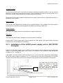
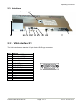
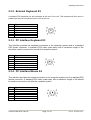
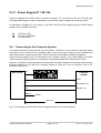
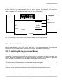
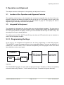
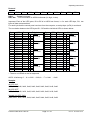
Operating Instructions Control Panel SCD 1297-K (1) Operating Instructions SCD 1297-K (1) (Rack 19") 6AV8100-0BC00-0AA1 (Int.ID:6GF66240-7MA01) SCD1297-KT (1) 6GF6240-7MB Copyright Siemens AG Control Panel SCD 1297-K Page 1 / 31 DOC-Nr.: B4 0003E1.DOC Operating Instructions No part of this document may be reproduced or transmitted without express permission. Violations will result in prosecution. All Rights reserved. 2001 All Rights reserved. Control Panel SCD 1297-K Page 2 / 31 DOC-Nr.: B4 0003E1.DOC Operating Instructions Contents 1. Overview................................................................................................................... 5 1.1. Layout of this Handbook ............................................................................................ 6 1.2. Warnings and Safety Notes ....................................................................................... 7 1.2.1. Instructions for Handling Assemblies Susceptible to Electrostatic Shock............ 8 2. General Installation.................................................................................................. 9 2.1. Removal of Packaging and Checking of Individual Parts........................................... 9 2.2. Installation of the Monitor......................................................................................... 10 2.2.1. Installation of the AC/DC-power supply unit or 24V DC/DC Converter.............. 12 2.3. Interfaces................................................................................................................. 13 2.3.1. VGA-Interface X1 .............................................................................................. 13 2.3.2. External Keyboard X2 ....................................................................................... 14 2.3.3. PC Interface Keyboard X3................................................................................. 14 2.3.4. PC Interface Mouse X4 ..................................................................................... 14 2.3.5. PC Interface Keyboard/Mouse (Long Distance) X27......................................... 15 2.3.6. Service Connector X6 ....................................................................................... 15 2.3.7. Power Supply X7 / X8 / X9 ................................................................................ 16 2.4. Connecting to the Computer System ....................................................................... 16 2.5. Electrical Installation ................................................................................................ 17 2.5.1. Installing the Keyboard and Mouse ................................................................... 17 3. Operation and Alignment ...................................................................................... 18 3.1. Location of the Operation and Alignment Controls .................................................. 18 3.2. Integrated Foil keyboard .......................................................................................... 18 3.2.1. Programming the Keys...................................................................................... 18 3.2.2. Key Definition Table .......................................................................................... 19 3.2.3. Programming the LEDs ..................................................................................... 20 3.3. Integrated Mouse (Finger-mouse) ........................................................................... 22 3.4. Display Alignment .................................................................................................... 22 3.4.1. Aligning the Display via an External Keyboard.................................................. 22 3.4.2. OSD-Menu ........................................................................................................ 23 3.4.3. Quick-OSD-Menu-Functions ............................................................................. 24 3.4.4. OSD-Menu-Function ......................................................................................... 25 4. 4.1. 4.2. 4.3. 4.4. 4.5. 4.6. 4.7. 4.8. Technical Data ....................................................................................................... 27 Display module ........................................................................................................ 27 Power Supply........................................................................................................... 27 Operating Conditions ............................................................................................... 27 Protection................................................................................................................. 28 Enclosure................................................................................................................. 28 Input Signal (Video) ................................................................................................. 28 EU Declaration of Conformity on EMC..................................................................... 29 Additional Licensing................................................................................................. 29 5. Appendix ................................................................................................................ 30 Control Panel SCD 1297-K Page 3 / 31 DOC-Nr.: B4 0003E1.DOC Operating Instructions Figures Fig. 2: Connecting the SCD 1297-K to the computer system over a short distance....................... 16 Fig. 3: Connecting the SCD 1297-K to the computer system over a longer distance ..................... 17 Fig. 4: Key definition table ............................................................................................................. 19 Fig. 8: Keyboard matrix ................................................................................................................. 30 Fig. 10: MF2 key numbers............................................................................................................. 31 Control Panel SCD 1297-K Page 4 / 31 DOC-Nr.: B4 0003E1.DOC Operating Instructions 1. Overview The SCD 1297-K is a control panel for PC-compatible computer systems and can be used as a man machine interface (MMI) platform for a wide variety of visualisation systems. Special interfaces make it possible to have the SCD 1297-K in a different location as the computer system. Ninety-four keys and a “finger mouse” are provided for software control and operation. The 94 keys can be individually configured. The SCD 1297-K was developed and constructed especially for industrial applications. Its compact 19” rack format enables it to be used in applications where a complete computer system would be unsuitable, due to space or environmental restrictions or where the computer and operating interface must be in different rooms. As is the case for all industrial systems, the SCD 1297-K has been designed to withstand the particular demands placed on such equipment, e.g., it is resistant to electromagnetic radiation and can withstand a large temperature range. The TFT-LCD display in this control panel minimises picture geometry distortion and colour patches. The screen remains flicker-free even at the low refresh rate of 50 Hz. Images of higher or lower resolution than that of the screen will be contracted or expanded to fit on the display. The SCD 1297-K can display up to 256k (16.7 million using interpolation) colours simultaneously allowing true colour images and videos to be displayed without limitations. The SCD 1297-K contains special hardware to convert the incoming VGA signal into a form recognisable to the display controller thus guaranteeing compatibility with standard CRT monitors. A clear and easy-to-use OSD (On Screen Display) is used to adjust the alignment of the display. The “Automatic Alignment” feature removes the necessity for tedious adjustments of picture position and phase, etc. At the press of a button, the monitor performs the alignment automatically. The SCD 1297-K is equipped with an active 12.1” colour TFT display module with a resolution of 800x600 pixels. The VESA DPMS power management system allows significant reduction in power consumption when the synchronisation signal from the computer has been switched off, compared with that under “normal” operation. Control Panel SCD 1297-K Page 5 / 31 DOC-Nr.: B4 0003E1.DOC Operating Instructions 1.1. Layout of this Handbook This handbook should be kept within reach when installing and operating the SCD 1297-K. It has been laid out so that even inexperienced users can find the information they require. Chapters are clearly arranged according to subject. In detail, the chapters are arranged as follows: • Chapter 1 Introduction This chapter provides a brief description of the SCD 1297-K, including its properties, application areas and special features. • Chapter 2 Installation This chapter is mainly concerned with preparing the LCD monitor for use, its installation, cabling and connection with the computer system. • Chapter 3 Operation All operation and adjustment possibilities for the SCD 1297-K are described here. Instructions on how to program the foil keys are also included. • Chapter 4 Technical Data This chapter contains technical details such as dimensions, power supply, environmental considerations and EMC data. Important: We have gone to great lengths to match the quality of the documentation to the high standard of this product. We are grateful for the support of our customers. Control Panel SCD 1297-K Page 6 / 31 DOC-Nr.: B4 0003E1.DOC Operating Instructions 1.2. Warnings and Safety Notes Transport The LCD monitor should only be transported in its original packaging. This is the only way to ensure it will be protected against shocks and rough treatment. Setting up When installing, it should be noted whether any moisture (condensation) has entered the unit during transport or storage. Additional important installation information can be found in the “Technical Data” chapter. EMC This is a Class A piece of equipment and conforms to the regulations concerning interference emission and interference resistance for industrial equipment. Repairs Before the unit is opened, it must be switched off and the power supply disconnected. Only authorised persons may open the unit. Additions or changes to the unit may damage the system or affect its EMC behaviour. Cleaning The unit must be isolated from the power supply before cleaning. If heavily soiled, the SCD 1297-K can be cleaned with a damp cloth and mild detergent. Care must be taken to ensure that no moisture enters the unit during cleaning. Scouring powders and solvents must never be allowed to come in contact with the unit. The inside of the unit is to be cleaned by qualified service technicians only. Control Panel SCD 1297-K Page 7 / 31 DOC-Nr.: B4 0003E1.DOC Operating Instructions 1.2.1. Instructions for Handling Assemblies Susceptible to Electrostatic Shock Most of the assemblies within the SCD 1297-K contain components which can be destroyed by electrostatic voltages. It is also possible for the assemblies to be damaged in such a way that total failure does not occur. If you (as an authorised service technician) are handling such assemblies, then the following precautions should be observed: • When such assemblies are being handled, a means of electrostatic discharge must be available. This can be, for example, an earthed object, which can be touched to discharge electrostatic voltages. • This also applies to all tools used (insulated). They must also be discharged at an earthed object. • When assemblies are removed or added to the system, the unit must always be switched off and the power supply cable unplugged. • The vulnerable assemblies should always be held by their edge. Avoid touching tracks and contact pins. Control Panel SCD 1297-K Page 8 / 31 DOC-Nr.: B4 0003E1.DOC Operating Instructions 2. General Installation Preparation for installing the LCD monitor includes the following points: • Removal of all packaging • Checking of components for damage • Comparison of components received with those on the delivery note • Connection to the computer system and power supply • Building into your system, bearing in mind technical and ergonomic aspects 2.1. Removal of Packaging and Checking of Individual Parts After unpacking all the delivered components, they should be checked for completeness and for possible transport damage (visual inspection). If any deficiencies are found then please contact the service department given on the delivery note. Have the delivery note number, serial number and a description of the deficiency to hand. The original packaging should be kept for future transportation. Control Panel SCD 1297-K Page 9 / 31 DOC-Nr.: B4 0003E1.DOC Operating Instructions 2.2. Installation of the Monitor The SCD 1297-K is a 19” rack module and is mounted in a standard 19” cabinet. Guide rails are not necessary. SI EM EN S 25 Bracket for mounting the AC/DCpower supply unit Fig. 1: Dimensions of the SCD 1297-K Control Panel SCD 1297-K Page 10 / 31 DOC-Nr.: B4 0003E1.DOC Operating Instructions Control Panel SCD 1297-K Page 11 / 31 DOC-Nr.: B4 0003E1.DOC Operating Instructions Thermal Problems In order that the SCD 1297-K maintains an optimum operating temperature while in use, air must be allowed to circulate freely around the enclosure. This is especially important for the rear of the unit. A convection current must be allowed to circulate around the enclosure Please bear in mind that increased temperatures can lead to defects and to a significant reduction in the lifetime of the monitor. EMC Problems This unit has been designed for building into an industrial system. The operator of the entire plant is responsible for maintaining electromagnetic compatibility according to EMC laws. Safety Problems All voltage and signal connections must ad here to legal requirements. Ergonomics The screen should be easily viewable from all sides without reflections. A high-quality 75-ohm coaxial cable must be used for the VGA signals. Low quality cables can result in interference and shadowing on the display. 2.2.1. Installation of the AC/DC-power supply unit or 24V DC/DC Converter Either an AC/DC power supply unit or a DC/DC converter can be used to supply the control panel with 24VDC. If an AC/DC power supply unit is used, it is attached to the enclosure using the bracket indicated in Fig. 1 on page 10 If the DC/DC converter, which is delivered with the unit, is to be used then it should be inserted below the AC/DC power supply unit shown in Fig. 1, so that the 24V connector is accessible. The DC/DC converter should then be screwed to the enclosure using to the two holes provided for the bracket. Insert the DC/DC converter under the cover The cable from the AC/DC power supply unit (12VDC) or from the DC/DC converter is plugged directly into the socket (power) on the SCD 1297-K. It should be secured using a pull-relief. Screwholes for the DC/DC converter Control Panel SCD 1297-K Page 12 / 31 DOC-Nr.: B4 0003E1.DOC Operating Instructions 2.3. Interfaces Buttons for OSD X8 X9 X2 X27 X4 X3 X1 X6 X7 2.3.1. VGA-Interface X1 The VGA interface is a standard 15-pin female HD-D-type connector. Pin 1 2 3 4 5 6 7 8 9 10 11 12 13 14 15 Signal Video input RED Video input GREEN Video input BLUE Not used Not used GND (RED) GND (GREEN) GND (BLUE) Not used GND Not used Not used H-Sync. V-Sync. Not used Control Panel SCD 1297-K Page 13 / 31 DOC-Nr.: B4 0003E1.DOC Operating Instructions 2.3.2. External Keyboard X2 A standard PS2 keyboard can be connected at the rear of the unit. This keyboard will then work in parallel with the built in keyboard on the front of the unit. Pin 1 2 3 4 5 6 Signal Data GND +5V CLK - 2.3.3. PC Interface Keyboard X3 This interface provides the keyboard connection to the computer system and is a standard PS2 female connector. A standard PS2 cable (male-male) with a maximum length of 5m should be used to connect the unit with the computer system. Pin 1 2 3 4 5 6 Signal Data GND +5V CLK - 2.3.4. PC Interface Mouse X4 This interface provides the mouse connection to the computer system and is a standard PS2 female connector. A standard PS2 cable (male-male) with a maximum length of 5m should be used to connect the unit with the computer system. Pin 1 2 3 4 5 6 Signal Data GND +5V CLK - Control Panel SCD 1297-K Page 14 / 31 DOC-Nr.: B4 0003E1.DOC Operating Instructions 2.3.5. PC Interface Keyboard/Mouse (Long Distance) X27 This interface is used when the computer system and the control panel are separated by more than 5m. The mouse and keyboard signals are transmitted via a common cable. A standard CAT5/6/7 ethernet cable with an RJ45 connector is used. If this interface is used the PC must have a corresponding receiver which can convert the incoming signals back to standard keyboard and mouse signals (see page 17) Pin 1 2 3 4 5 6 7 8 Signal KBD-DATA+ KBD-DATAMOUSE-DATAKBD-CLK+ KBD-CLKMOUSE-DATA+ MOUSE-CLKMOUSE-CLK+ 2.3.6. Service Connector X6 This female connector is used for updating the SCD 1297-K software. Control Panel SCD 1297-K Page 15 / 31 DOC-Nr.: B4 0003E1.DOC Operating Instructions 2.3.7. Power Supply X7 / X8 / X9 Power is supplied to the SCD 1297-K via a DC connector, X7, on the rear of the unit. The DC input (12V) has been design to make it impossible to connect the supply voltage the wrong way round. As described in Chapter 2.2.1 on page 12, the SCD 1297-K can be supplied using an AC/DC power supply unit or a DC/DC converter. X7 X8 X9 DC input (12V) AC input (100-240V) DC input (24V) 2.4. Connecting to the Computer System The monitor has been tested and set up at the factory. Therefore, all the remains to be done before using the unit is to connect all the necessary cables, such as the power supply, mouse, keyboard and video (VGA) to the connectors provided. These connections must adhere to EMC regulations. There are two possible ways of connecting to the computer system. If the cable between the SCD 1297-K and the computer system is less than 5m long then standard PS2 cables can be used. However, it should be noted that these interfaces have not been designed for industrial environments. External interference can affect the computer system or even put it out of operation. Use a X27 connection (see fig. 3) SCD 1297-K X2 Computer system X1 VGA X3 Keyboard (PS2) X4 X8/X9 Mouse (PS2) Power max. 5m Fig. 2: Connecting the SCD 1297-K to the computer system over a short distance Control Panel SCD 1297-K Page 16 / 31 DOC-Nr.: B4 0003E1.DOC Operating Instructions If the control panel and the computer system are further apart or if there are strong interference fields in the vicinity then the second variation using the special interface (long distance, X27) should be used for the mouse and keyboard. Here, both mouse and keyboard signals are transmitted over one cable, a standard CAT 5/6/7 ethernet cable (note the signal configuration). X2 Computer system SCD 1297-K X1 VGA Keyboard ( PS2) Keyboard/ mouse signal converter X27 X8/X9 Mouse ( PS2) Power Up to 20m Fig. 3: Connecting the SCD 1297-K to the computer system over a longer distance 2.5. Electrical Installation Before applying power to the SCD 1297-K, check that all connectors are plugged in correctly and secured. If a VGA signal is present, a picture should appear immediately on the display. 2.5.1. Installing the Keyboard and Mouse When a computer starts up it usually checks and initialises the keyboard and mouse. If either is not connected or is connected incorrectly, the computer’s start up procedure may stop or else the input device may not be available after it has been subsequently connected. This is especially applicable when a mouse is connected to a PC compatible computer after it has booted up. The keyboard and/or the mouse should not be plugged in or unplugged while the computer is running. This could result in misinterpretation of the keyboard codes/mouse signals. Therefore, the control panel should always be switched on before or at the same time as the computer system so that the keyboard and mouse are recognised and initialised correctly. Control Panel SCD 1297-K Page 17 / 31 DOC-Nr.: B4 0003E1.DOC Operating Instructions 3. Operation and Alignment This chapter contains a description of the operating and alignment functions. 3.1. Location of the Operation and Alignment Controls The operating controls such as the keyboard and mouse are accessible from the front of the unit. Buttons for aligning the display are located on the rear of the unit. The location of the 4 keys for the OSD can be seen in Fig. 1: Dimensions of the SCD 1297-K on page 10. The display can also be aligned using an externally connected PS2 keyboard. 3.2. Integrated Foil keyboard The integrated foil keyboard has 94 keys which can each be defined separately. The keys can be separated into two groups. One group consists of the so-called softkeys, which are located to the left of, to the right and above the display. These keys can be labelled with the help of a slide in strip. The second group of keys is already labelled. The softkeys and the HELP, SHIFT and ACK keys also have an LED each which can be switched on and off via the keyboard interface. 3.2.1. Programming the Keys All the keys in the integrated foil keyboard can be freely programmed. A small DOS program, “TCLOAD.EXE” is used to program the keys via the keyboard interface. The keys are defined in an editable list or an Excel table. This is read and interpreted by the DOS program, which then sends these definitions to the control panel. Key definition TXT File DOS-Program TCLOAD.EXE Exceltable Save as... Control panel SCD 1297-K TXT File Important The TCLOAD.EXE program can only read and process text files. Therefore, in Excel, it is necessary to save the table using “Save as...” and to select the file type “Formatted text (space delimited)”. Control Panel SCD 1297-K Page 18 / 31 DOC-Nr.: B4 0003E1.DOC Operating Instructions 3.2.2. Key Definition Table Various keywords, characters and syntax are used in the table. The table, which is supplied with the control panel, contains definitions for all of the keys with permanent labels. ; Key table for control panel XXY at plant ZYX ; #Name Simatictable 23 ; ;Basic level, level 0 ; X (0...11) Y (0...7) 0 1 2 3 4 5 6 7 MF-II Key No. 0 19 0 38 0 17 0 18 0 11 0 6 0 83 0 76 Flags T T T T T T T T ; ; ; ; ; ; ; ; Comments E K Q W 0 5 Cursor Up Delete Fig. 4: Key definition table The table consists of a header in which the user can enter information as comments, the key definition table for the first key level and the key definition table for the second key level. The key, which will be used to switch between the two levels, is defined between the tables for the two key levels. Keywords/characters #Name #Level1 The table can be given a name here. This name is stored in the control panel and is used for subsequent identification of the loaded table. The key (co-ordinates) used to switch between the two levels follows this keyword. Example: #Level1 8 6 i.e. the key, X=8, Y=6, will be used as the shift key. ; A semi-colon indicates the start of a comment. Control Panel SCD 1297-K Page 19 / 31 DOC-Nr.: B4 0003E1.DOC Operating Instructions Syntax of a table entry X key co-ordinate Y key co-ordinate Key number Flag Comment The individual entries like X key co-ordinate and Y key co-ordinate must be separated by a space. Key co-ordinates This matrix co-ordinate specifies the key to be defined. Fig. 5 on page 30 in the appendix shows all the SCD 1297-K keys and their co-ordinates. Key number The key number refers to the equivalent MF2 key. Fig. 6 on page 31 in the appendix shows the key numbers for a standard MF2 keyboard. Only key numbers are exchanged between a computer and a keyboard. The definition of a key, i.e., whether a “Z” or a “Y” appears on the screen is determined by tables (keyboard drivers) stored in the computer. Flags The flags define specific behaviour, e.g., which control key should also be activated when this key is pressed: R,r L,l G,g A,a C,c T,t Right shift key Left shift key AltGr key Alt key Control key / Strg key Autorepeat, Typematic Comment Comments begin with a semi-colon character, “;”. The end of line character (CR or CR/LF) indicates the end of the comment. 3.2.3. Programming the LEDs The foil keyboard has 39 LEDs which are arranged in combination with some of the keys. These LEDs can be used, for example, as receipt or ready signals. The LEDs are switched via the keyboard connection between the computer and the control panel, in a similar manner to the programming of the keys. A special command has been implemented for driving the LEDs since, in the MF2 specification, there are only NumLock, CapsLock and ScrollLock LEDs. This command enables the individual LEDs to be switched on and off. The correlation between LED number and LED position is shown in Fig. 5 on page 30. The special command for LED data is 0xEA followed by 10 bytes of LED information. Control Panel SCD 1297-K Page 20 / 31 DOC-Nr.: B4 0003E1.DOC Operating Instructions Protocol 0xEA B1H B1L B2H B2L B3H B3L B4H B4L B5H B5L 0xEA : Special command BxH, BxL : LED Information in ASCII-Hexformat (H= high, L=low) Important: Each of the LED bytes, B1 to B5 is in ASCII hex format, i.e. for each LED byte, ‘Bx’, two bytes of data are transmitted. For each byte that the contral panel receives from the computer, a receipt byte (oxFA) is sent back. The correlation between the LED bytes B1 – B5 and the individual LEDs is shown below: Byte B1.0 B1.1 B1.2 B1.3 B1.4 B1.5 B1.6 B1.7 B2.0 B2.1 B2.2 B2.3 B2.4 B2.5 B2.6 B2.7 B3.0 B3.1 B3.2 B3.3 LED LED40* LED39 LED38 LED37 LED36 LED35 LED34 LED33 LED32 LED31 LED30 LED29 LED28 LED27 LED26 LED25 LED24 LED23 LED22 LED21 Taste Shift ACK Help F20 F19 F18 F17 F16 F15 F14 F13 F12 F11 F10 F9 F8 F7 F6 F5 X X X X X X X X Beispiel 0 ,B1L’ 1 A = 0x41 0 1 1 ,B1H’ 0 1 = 0x31 0 0 1 ,B2L’ 0 D = 0x44 1 1 0 ,B2H’ 0 4 = 0x34 1 0 0 ,B3L’ 1 E = 0x45 1 1 Byte B3.4 B3.5 B3.6 B3.7 B4.0 B4.1 B4.2 B4.3 B4.4 B4.5 B4.6 B4.7 B5.0 B5.1 B5.2 B5.3 B5.4 B5.5 B5.6 B5.7 LED LED20 LED19 LED18 LED17 LED16 LED15 LED14 LED13 LED12 LED11 LED10 LED9 LED8 LED7 LED6 LED5 LED4 LED3 LED2 LED1 Taste F4 F3 F2 F1 S16 S15 S14 S13 S12 S11 S10 S9 S8 S7 S6 S5 S4 S3 S2 S1 X X X X X X X X X X X Beispiel 1 ,B3H’ 1 B = 0x42 0 1 0 ,B4L’ 0 0 = 0x30 0 0 1 ,B4H’ 0 D = 0x44 1 1 0 ,B5L’ 0 8 = 0x38 0 1 1 ,B5H’ 1 F = 0x46 1 1 *: There is no LED40 on the foil keyboard. ASCII - Kodierung: 0 ... 9 => 0x30 ... 0x39; A ... F => 0x41 … 0x46 Samples: all LED „ON“ 0xEA, 0x46, 0x46, 0x46, 0x46, 0x46, 0x46, 0x46, 0x46, 0x46, 0x46 all LED “OFF” 0xEA, 0x30, 0x30, 0x30, 0x30, 0x30, 0x30, 0x30, 0x30, 0x30, 0x30 Sampel (X= LED “ON“): 0xEA, 0x31, 0x41, 0x34, 0x44, 0x42, 0x45, 0x44, 0x30, 0x46, 0x38 Control Panel SCD 1297-K Page 21 / 31 DOC-Nr.: B4 0003E1.DOC Operating Instructions 3.3. Integrated Mouse (Finger-mouse) The “finger-mouse” on the front of the control panel fulfils the same function as a standard Microsoftcompatible 2-button mouse. The mouse is moved using the central positioning surface. The surface should be pressed in the desired direction. The degree of pressure applied translates to the speed at which the mouse moves. The buttons to either side correspond to the left and right mouse buttons. Left mouse button Mouse positioning surface Right mouse button 3.4. Display Alignment Since there are no standards for video output signals from VGA cards, the first time the unit is switched on, it automatically adjusts to the graphic card in use. 3.4.1. Aligning the Display via an External Keyboard As already mentioned, the OSD can be operated from an external MF2 keyboard. The cursor keys are used to navigate in the OSD (see Fehler! Verweisquelle konnte nicht gefunden werden.Keys for the OSD menu, on page Fehler! Textmarke nicht definiert.) In order to activate the OSD via an external keyboard, the keys CRTL, ALT and “M” should be pressed simultaneously. If no other keys are pressed within 10 seconds then the display switches back to the normal keyboard mode. The OSD also disappears from the display after around 10 seconds (depending on the setting in the utility menu). Control Panel SCD 1297-K Page 22 / 31 DOC-Nr.: B4 0003E1.DOC Operating Instructions 3.4.2. OSD-Menu The „On Screen Display“ OSD is a menu system, which is shown on the display. With the help of OSD and the described controls elements, all adjustments of the monitor are executable. There are just 4 keys S1 to S4 to control the OSD. OSD-Menu / Quick-OSD-Menu In addition to the OSD menu there are more possibilities to adjust important functions like brightness, contrast and automatic adjustment directly via a Quick-OSD-menu. Function(s) of the control keys: <+> Increase value, menu navigation (go to sub menu / go to right) Invoke Quick-OSD-menu: To execute an automatic adjustment <-> Decrease value, menu navigation (go to left) MENU Invoke OSD Menu navigation (switching between main- and sub-menu) SET Menu navigation (go down) Invoke Quick-OSD-menu: Brightness and contrast adjustment Control Panel SCD 1297-K Page 23 / 31 DOC-Nr.: B4 0003E1.DOC Operating Instructions 3.4.3. Quick-OSD-Menu-Functions Following adjustments can do via the Quick-OSD-menu: Brightnes Contrast Auto adjust Invoke via key <SET> Function Adjustment/value Description Contrast Range: 0 via key <+>/<-> to 100 Contrast adjustment Brightness Range: 0 via key <+>/<-> to 100 Brightness adjustment Invoke via key <+> Function Adjustment/value Automatic image adjustment Press key <+> to start the Perform an automatic image adjustment adjustment. Adjustment of frequency, phase and image position. Control Panel SCD 1297-K Description Page 24 / 31 DOC-Nr.: B4 0003E1.DOC Operating Instructions 3.4.4. OSD-Menu-Function Invoke via key <MENUE> Main menu Function Adjust function / value / range Picture 1 Brightness setting 0 to 100 through key (+/-) range: adjust brightness Contrast setting 0 to 100 through key (+/-) range: adjust contrast change contrast between dark and light colors H Position setting 0 to 100 through key (+/-) range: move picture in horizontal direction V-Position setting range 0 to 100 through key (+/-) : move picture in vertical direction Phase setting range 0 to 31 through key (+/-) : adjust phase of input signal Frequency setting 950 to 1050 through key (+/-) Picture 2 Sharpness range (dependent to Description : picture) adjust frequency of input signal 1, 2, 3, 4, 5 adjust sharpness of the picture by using no. 1 to 5 Gamma Linear or CRT correction of gamma curve value of colors will be forwarded to the display Color temperature 5000 1=sharp, 5= soft - 6500 – 9300 - VAR color temperature / adjust color three defined and one adjustable color temperatures are for selection activate „VAR“ - for RGB shows up a adjustment beam. 100 % (50% correspond to factor 1) Option 1 0 to OSD select between nine defined OSD positions f OSD H-Position setting range 0 to 100 through key (+/-) : move OSD-menu in horizontal position define position OSD OSD V-Position setting range 0 to 100 through key (+/-) : move OSD-menu in vertical position OSD timeout 5 ... 60 seconds adjust time after the OSD menu is automatically fade out the adjustment ensures between 5 to 60 s in steps of5 s. OSD background Opaque – Transparent select background color of the OSD menu you have the choice between transparent and colored background. Backlight setting range 0 to 100 through key (+/-) Noise suppression ON - OFF : adjust brightness ob backlight display herewith you can match the brightness of the picture with the brightness of the room. Standard adjustment OFF. By ON: Activate the function noise suppression. This function suppresses interference at the sync signal lines to avoid A new auto adjustment during short interference. Control Panel SCD 1297-K Page 25 / 31 DOC-Nr.: B4 0003E1.DOC Operating Instructions Main menu Function Adjust function / value / range Description Option 2 DPMS ON – OFF Display Power Management System (DPMS) on or off If DMPS activated, the monitor is turn off (backlight) when a synch signal is left. The screen is dark. Source scan OFF – ON – Standard Standard: ON Note: To scan new video source is not relevant because the monitor has one RGB input source only. Choose the background color of the screen when no input signal is present. Blank color red – reen – blue – black Display – Display resolution (not from the input source) Info signal source ON – OFF Input source icon on or off The icon is shown when input signal are changed. The icon shows the following information’s: Utilities Language Englisch – German Calibration <+> press - signal source (e.g. RGB analog) - Mode number (internal mode number of the timing list) - Image resolution of the input signal - H- and V-frequency OSD language Adjustment of the internal A/D converter (following the menu instruction) Factory reset Installation Mode RGB- <+> press Reset of values like brightness, contrast,.. to default values <+> press Enter a new timing which is not in the internal timing table. This function should used, when the shown image resolution is not the resolution are expect. When press <+> the sub menu expect 9 timing parameter. When <+>, Hand Frequency V- – Show the H- and V-Frequency of the present input signal. H/V-total, H/V-start – Show the used timing parameter of the present input signal Option Var. RGB-Mode inactive, Mode1, Mode2, Mode3 Inaktiv: used the internal timing table only Mode1: use the timing parameter and perform a complete auto adjustment. (usually used) Mode2: use the timing parameter and perform an auto adjustment without an automatic image position adjustment. Mode3: use the timing parameter and perform an auto adjustment without an automatic frequency adjustment. H-resolution 100 to 2000 through key (+/-) Horizontal image resolution (important parameter) V-resolution 100 to 2000 through key (+/-) Vertical image resolution (important parameter) H-total 100 to 2500 through key (+/-) Whole pixel per line (important parameter) H-Start 0 to 750 through key (+/-) Number of Pixels from H-sync start to image start V-Start 0 to 500 through key (+/-) Number of lines from V-sync start to image start Install Info <+> press Activate the feed timing parameter test pattern <+> press Show a test image Firmware, Resolution, Timing – Show the firmware version and timing data of the present input signal Control Panel SCD 1297-K Page 26 / 31 DOC-Nr.: B4 0003E1.DOC Operating Instructions 4. Technical Data 4.1. Display module Type Active colour TFT-LCD Diagonal size 30.8 cm (12.1") Display area (WxH) 246.0 x 184.5 mm Resolution 800 x 600 pixels Pitch 0.33 x 0.33 mm² Colours 262144 Backlight 2xCCFT (Cold Cathode Fluorescent Tube) Brightness (typical) approx. 250 cd/m² 4.2. Power Supply Input voltage DC (X7) 10 – 14VDC Input voltage AC (X8) 100 –240 V AC, 50/60 Hz Input voltage DC (X9) 18 – 36VDC Power consumption DC(normal operation) approx. 25 W Power consumption DC(StandBy) approx. 7 W 4.3. Operating Conditions Operating temperature +5 to +45°C Storage temperature -25 to +60°C Humidity Max. 95% (non condensing) Control Panel SCD 1297-K Page 27 / 31 DOC-Nr.: B4 0003E1.DOC Operating Instructions 4.4. Protection Protection class - front IP65 Protection class - rear IP20 4.5. Enclosure Weight approx. 4.5 kg Enclosure material Aluminium 4.6. Input Signal (Video) Level 0.7Vss RGB analog at 75Ω Bandwidth 140 MHz (-3 dB) Impedance 75 Ω Synchronisation - Sep. Sync. (TTL) - Sync on green - Composite Sync H frequency 30 to 75 kHz V frequency 50 to 100 Hz Control Panel SCD 1297-K Page 28 / 31 DOC-Nr.: B4 0003E1.DOC Operating Instructions 4.7. EU Declaration of Conformity on EMC Product LCD-Monitor SCD 1297-K Test foundations EU framework guidelines No. 89/336/EWG No. 92/031/EWG No. 73/23/EWG No. 93/68/EWG Harmonised standards EN 50081-2 used (EN55022 Class A) Interference emissions Interference resistance EN61000-6-2 EN610003-2 EN610003-3 EN 60950 Edition 11/1997 Safety This piece of equipment also fulfils the requirements of FCC Class A. 4.8. Additional Licensing This piece of equipment has CE, UL and CUL licensing (corresponds to CSA). Control Panel SCD 1297-K Page 29 / 31 DOC-Nr.: B4 0003E1.DOC Operating Instructions SIEM ENS 5. Appendix Fig. 5: Keyboard matrix Control Panel SCD 1297-K Page 30 / 31 DOC-Nr.: B4 0003E1.DOC VZ R KY[ Y ZW E ] >VX? >V VW T G U > 2 = ! H 3 0 " I 1 # $ J 4 ? % K 5 @ & L / 6 A ' M . 7 S B ( N R - 8 F ) O Q , C * + P 9 D : ; < VW Y ZW VZ [ KY[ KY[ [ L\ ÷ KY[ × P ; V Operating Instructions Fig. 6: MF2 key numbers Control Panel SCD 1297-K Page 31 / 31 DOC-Nr.: B4 0003E1.DOC