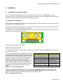
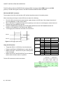
1
DENSITÉ series HCO-1822 HD/SD/ASI Change Over with Clean Switch and ALC Guide to Installation and Operation M955-9900-100 28 Jan 2011 Miranda Technologies Inc. 3499 Douglas-B.-Floreani St-Laurent, Québec, Canada H4S 2C6 Tel. 514-333-1772 Fax. 514-333-9828 www.miranda.com © 2011 Miranda Technologies Inc. GUIDE TO INSTALLATION AND OPERATION Electromagnetic Compatibility This equipment has been tested for verification of compliance with FCC Part 15, Subpart B requirements for Class A digital devices. NOTE: This equipment has been tested and found to comply with the limits for a Class A digital device, pursuant to part 15 of the FCC Rules. These limits are designed to provide reasonable protection against harmful interference when the equipment is operated in a commercial environment. This equipment generates, uses, and can radiate radio frequency energy and, if not installed and used in accordance with the instruction manual, may cause harmful interference to radio communications. Operation of this equipment in a residential area is likely to cause harmful interference in which case the user will be required to correct the interference at his own expense. This equipment has been tested and found to comply with the requirements of the EMC directive 2004/108/CE: • EN 55022 Class A radiated and conducted emissions • ENV 50204 Radiated EMF Immunity – RF 900 MHz Pulsed • EN 61000-3-2 Harmonic current emission limits • EN 61000-3-3 Voltage fluctuations and flicker limitations • EN 61000-4-2 Electrostatic discharge immunity • EN 61000-4-3 Radiated electromagnetic field immunity – radio frequencies • EN 61000-4-4 Electrical fast transient immunity • EN 61000-4-5 Surge transient immunity • EN 61000-4-6 Conducted disturbances immunity • EN 61000-4-11 Voltage-dips, short-interruption and voltage variation immunity How to contact us: For technical assistance, please contact the Miranda Technical support centre nearest you: Americas Telephone: +1-800-224-7882 e-mail: [email protected] Asia Telephone: +852-2539-6987 e-mail: [email protected] Europe, Middle East, Africa, UK Telephone: +44 (0) 1491 820222 e-mail: [email protected] China Telephone: +86-10-5873-1814 e-mail: [email protected] France (only) Telephone: +33 (0) 1 55 86 87 88 e-mail: [email protected] Visit our web site at www.miranda.com HCO-1822 GUIDE TO INSTALLATION AND OPERATION Table of Contents 1 HCO-1822 HD/SD/ASI Change Over with Clean Switch and ALC .......................................... 1 1.1 1.2 1.3 1.4 2 Installation .................................................................................................................................. 3 2.1 2.2 3 Installation in the Densité frame.......................................................................................................... 3 Rear Panel Connector ........................................................................................................................ 3 Operation .................................................................................................................................... 5 3.1 3.2 3.3 3.4 4 Introduction ......................................................................................................................................... 1 Features .............................................................................................................................................. 1 Block Diagram ..................................................................................................................................... 2 Front Card-edge Interface................................................................................................................... 2 Control options .................................................................................................................................... 5 Card-Edge Status LED ....................................................................................................................... 5 Local control using the Densité frame control panel ........................................................................... 6 3.3.1 Overview ................................................................................................................................ 6 3.3.2 Menu for local control............................................................................................................. 6 Remote control using iControl............................................................................................................. 7 3.4.1 The iControl graphic interface window ................................................................................... 7 3.4.2 The Switch panel ................................................................................................................... 8 3.4.3 The Alarms panel ................................................................................................................. 11 3.4.4 The Timing panel ................................................................................................................. 16 3.4.5 The Operation Mode panel .................................................................................................. 17 3.4.6 The Reference panel ........................................................................................................... 18 3.4.7 The Audio Embed panel ...................................................................................................... 18 3.4.8 The Miranda ALC panel ....................................................................................................... 19 3.4.9 The Fingerprint panel ........................................................................................................... 22 3.4.10 The RALM panel .................................................................................................................. 23 3.4.11 The Thumbnail panel ........................................................................................................... 25 3.4.12 The Options panel ................................................................................................................ 25 3.4.13 The Factory panel ................................................................................................................ 27 3.4.14 The Alarm Config panel ....................................................................................................... 28 3.4.15 The Info panel ...................................................................................................................... 30 3.4.16 User Presets ........................................................................................................................ 32 3.4.17 Profiles ................................................................................................................................. 32 Specifications........................................................................................................................... 35 ANNEX – HCO-1822 User Interface .............................................................................................. 36 HCO-1822 GUIDE TO INSTALLATION AND OPERATION HCO-1822 GUIDE TO INSTALLATION AND OPERATION 1 HCO-1822 HD/SD/ASI Change Over with Clean Switch and ALC 1.1 Introduction The HCO-1822 is a 2x1 HD/SD/ASI change-over which supports 16 channels of embedded audio and Metadata. Change-overs are performed electronically by the HCO-1822’s internal router. The module can perform a video and audio “Clean & Silent Switch” between sources using the CS option. In the event of a power failure, the signal is protected by relays fitted on the rear module, maintaining the integrity of the selected signal at the output. Relays are fully controllable via the GPI interface. Input selection can be performed automatically or manually. In automatic mode, the card will perform input selection based on internal signal analysis with alarm parameters, and the status of the inputs. In manual mode, channel selection can be undertaken from the Densité Controller, the iControl software, or simply by using a GPI. A GPI can be connected to an automation system or any simple GPI control panel. The GPI outputs give status of the selected source allowing tallys to be triggered. The preview output is user-selectable to follow the main program output or any of the video inputs. The HCO-1822 generates audio/video fingerprints for each of the different inputs. In combination with other cards streaming fingerprints for the same signals, an optional module in iControl can measure and report lip-sync errors through the entire chain of a broadcast facility. Miranda’s new Automatic Loudness Control (ALC) option can eliminate annoying loudness variations between programs and commercials. Up to 4 programs of 8 channels can be configured to provide independent loudness control. The module provides streaming video and audio level metering so an operator can remotely and effectively monitor the signal path using Miranda’s iControl facility monitoring and control system. The HCO-1822 is a 2RU card that fits a 2-slot rear module. Up to 10 modules can fit in a 2RU densité frame. . 1.2 • • • • • • • • • • • • • Features Two source inputs and two outputs: program and preview Supports HD (1080i50/59.94, 720p50/59.94), SD (525,625) or ASI input Electronic switching with relay back up (on rear module) maintains selected input with power loss Automatic mode using internal signal analysis with alarm parameters Manual change-over by local frame controller, iControl, iControl Solo or GPI Alarm reporting to iControl facility monitoring and control system Compatible with iControl end-to-end A/V fingerprint analyzer for lip-sync error detection and measurement GPI in & out (IN 1, IN 2, AUTO, BYPASS) Optional clean switch function (video and 16 channels of audio) Optional on-board Automatic Loudness Control by Miranda Reference input with passive loop-through Two line timing window with CS option Thumbnail and audio level meter streaming HCO-1822 | 1 GUIDE TO INSTALLATION AND OPERATION Block Diagram 1.3 The following block diagram shows the functionality of the HCO-1822. Figure 1.1 Functional block diagram HCO-1822 1.4 Front Card-edge Interface The front card-edge of the HCO-1822 incorporates two elements: Select Status LED (see section 3.2) Select Button (see section 3.3) Status • • HCO-1822 Select Button Status LED Figure 1.2 Front card-edge layout 2 | HCO-1822 GUIDE TO INSTALLATION AND OPERATION 2 Installation 2.1 Installation in the Densité frame The HCO-1822 and its associated rear connector rear panel must be mounted in a DENSITÉ frame. It is not necessary to switch off the frame’s power when installing or removing the card. See the DENSITÉ Frame manual for detailed instructions for installing cards and their associated rear panels. 2.2 Rear Panel Connector The HCO-1822 has multiple inputs and outputs, and making space for all the necessary connectors at the rear of the frame requires a double-width rear panel. With the double-width rear panel installed, the HCO-1822 must be installed in the right-most of the two slots covered by the panel in order to mate with the panel’s connectors. If it is placed in the wrong slot, the front panel LED will flash red. Move the card to other slot for correct operation. No damage will result to the card should this occur. Figure 2.1 HCO-1822-DRP-R Rear Panel The rear panel connections are as follows: REF IN – Studio reference input For external synchronization, connect a black studio reference signal to the BNC labeled REF IN. NB: The loop must be terminated if not used. The reference input must conform to SMPTE 170M/SMPTE 318M/ITU 624-4/BUT 470-6 for standard definition signals and SMPTE 274M / SMPTE 296M for high definition signals and is used to phase the HD/SD SDI outputs to the studio. A reference mismatch may occur if there is a difference between the input video format’s frame rate and the reference format’s frame rate. When a mismatch occurs, an input error will be flagged and the card-edge Status LED will turn red to indicate the mismatch. The table shows the supported reference signals with respect to the input signals: HD/SD IN – serial digital HD/SD input Supported input signals Reference 525 (SMPTE-259M-C) NTSC (SMPTE-170M) 625 (SMPTE-259M-C) PAL (ITU 624-4) 1080i50 (SMPTE-274M) 1080i50, PAL 1080i59.94 (SMPTE-274M) 1080i59.94, NTSC 720p50 (SMPTE-296M) 720p50, PAL 720p59.94 (SMPTE-296M) 720p59.94, NTSC ASI (EN50083-9) ------- Connect up to two serial digital video signal, conforming to the SMPTE 292M standard for HD input signals and SMPTE 259M standard for SD input signals, to the BNC labeled HD/SD SDI IN. DVB-ASI per EN 50083-9 is also supported. The HCO-1822 will automatically switch to the detected line format. OUT – serial digital video outputs HCO-1822 | 3 GUIDE TO INSTALLATION AND OPERATION The HCO-1822 provides two HD/SD SDI video outputs on BNC connectors, labeled PGM (program) and PVW (preview). The SDI video signals conform to the SMPTE 292M and SMPTE 259M-C standards. GPI IN and GPI OUT connectors The rear panel of the HCO-1822 includes a GPI interface that allows control of the switch process. When constructing and using an external GPI box, be aware of the following: 1. The HCO-1822 card monitors the external power supply voltage on the GPI input. If the voltage is less than 4V (per relay datasheet), an alarm will be raised. 2. When a GPI INPUT is triggered while the card is operating in auto mode, the card changes to manual mode and switches to the input selected by the GPI. 3. DO NOT TRIGGER BOTH GPI INPUTS AT THE SAME TIME OR ALLOW THE TRIGGER PULSES TO OVERLAP, AS DAMAGE TO THE RELAY MAY RESULT. 4. A GPI trigger pulse should have a duration of at least 40 ms. Min pulse width=40 ms GPI IN 1 Min pulse width=40 ms GPI IN 2 Figure 2.2 GPI trigger pulse timing Using the GPI interface • WECO connector P1 P3 Trigger the GPI-IN-1 or GPI-IN-2 pin to select that input. • Trigger the AUTO-IN or BYPASS-IN pin to select that mode P4 • Read the GPI-OUT-1 and GPI-OUT-2 pins to identify which output is selected P5 • Read the AUTO-OUT and BYPASS-OUT pins to determine whether either of these modes is in operation. Pin number 1 2 3 1 2 3 1 2 3 1 2 3 GPI direction GPI name IN GND IN IN External +5V IN OUT GND OUT OUT GND OUT GPI-IN-1 The four GPI connectors are laid out as shown: Figure 2.3 GPI Connectors 4 | HCO-1822 GPI-IN-2 AUTO-IN BYPASS-IN GPI-OUT-1 GPI-OUT-2 AUTO-OUT BYPASS-OUT GUIDE TO INSTALLATION AND OPERATION 3 Operation 3.1 Control options The HCO-1822 can be controlled in different ways: • The local control panel and its push-buttons can be used to move through a menu of parameters and to adjust parameter values (see section 3.3). • Miranda’s iControl system can be used to access the card’s operating parameters from a remote computer, using a convenient graphical user interface (GUI). (see section 3.4) 3.2 Card-Edge Status LED The status monitor LED is located on the front card-edge of the HCO-1822, and is visible through the front access door of the DENSITÉ frame. This multi-color LED indicates the status of the HCO-1822 by color, and by flashing/steady illumination. The chart shows how the various error conditions that can be flagged on the HCO-1822 affect the LED status. • If a cell is gray, the error condition cannot cause the LED to assume that status • If more than one LED status is possible for a particular error condition, the status is configurable. See Section 3.4.14 for details. • The factory default status is shown by a The LED will always show the most severe detected error status that it is configured to display, and in the chart error severity increases from left to right, with green representing no error/disabled, and flashing red the most severe error. LED Status Error Condition No errors Green Yellow Red Flashing Red Backup Input Reference Presence Bypass Mode Video error Expected video format error Input timing out of range Reference mismatch Black detection Freeze detection Audio presence group Audio silence channel Rear presence error Card Fan If the LED is Flashing Yellow, it means that the card is selected for local control using the Densité frame’s control panel. See Section 3.3 for details. HCO-1822 | 5 GUIDE TO INSTALLATION AND OPERATION 3.3 Local control using the Densité frame control panel 3.3.1 Overview Push the SELECT button on the HCO-1822 card edge (see Section 1.4) to assign the local control panel to operate the HCO-1822. Use the control panel buttons to navigate through the menu, as described below. All of the cards installed in a Densité frame are connected to the frame’s controller card, which handles all interaction between the cards and the outside world. There are no operating controls located on the cards themselves. The controller supports remote operation via its Ethernet ports, and local operation using its integrated control panel. The local control panel is fastened to the controller card by a hinged connector, and when installed is located in the front center of the frame, positioned in front of the power supplies. The panel consists of a display unit capable of displaying two lines of text, each 16 characters in length, and five pushbuttons. The panel is assigned to operate any card in the frame by pushing the SELECT button on the front edge of that card. • Pushing the CONTROLLER button on the control panel selects the Controller card itself. • The STATUS LED on the selected card flashes yellow. CONTROLLER ESC + - SELECT Figure 3.1 Densité Frame local control panel The local control panel displays a menu that can be navigated using the four pushbuttons located beneath the display. The functionality of the pushbuttons is as follows: [+] [–] Used for menu navigation and value modification [SELECT] Gives access to the next menu level. When a parameter value is shown, pushing this button once enables modification of the value using the [+] and [–] buttons; a second push confirms the new value [ESC] Cancels the effect of parameter value changes that have not been confirmed; pushing [ESC] causes the parameter to revert to its former value. Pushing [ESC] moves the user back up to the previous menu level. At the main menu, [ESC] does not exit the menu system. To exit, re-push the [SELECT] button for the card being controlled. If no controls are operated for 30 seconds, the controller reverts to its normal standby status, and the selected card’s STATUS LED reverts to its normal operating mode. 3.3.2 Menu for local control The HCO-1822 has operating parameters which may be adjusted locally at the controller card interface. • Press the SELECT button on the HCO-1822 front card edge to assign the Densité frame’s local control panel to the HCO-1822 • Use the keys on the local control panel to step through the displayed menu to configure and adjust the HCO1822. The complete menu structure is shown in the Annex to this document, beginning on page 36. 6 | HCO-1822 GUIDE TO INSTALLATION AND OPERATION 3.4 Remote control using iControl The operation of the HCO-1822 may be controlled using Miranda’s iControl system. • • This manual describes the control panels associated with the HCO-1822 and their use. Please consult the iControl User’s Guide for information about setting up and operating iControl. In iControl Navigator or iControl Websites, double-click on the HCO-1822 icon to open the control panel. 3.4.1 The iControl graphic interface window The basic window structure for the HCO-1822 is shown in figure 3.2. The window identification line gives the card type (HCO-1822) and the slot number where the card installed in its Densité frame. 1 2 4 3 Figure 3.2 HCO-1822 iControl graphic interface window There are four main sections in the window itself, identified in figure 3.2: 1. The Status Icon area shows a series of six icons that report the status of some card parameters. Figure 3.3 shows the various forms that may appear; their meaning is described below. 1 2 3 4 5 6 A Icon 1 – Control status • A: Green - Remote Control via iControl • B: Yellow - Local control using the menu B Icon 2 – Reference status • • • A: Green - Locked to external reference B: Red - Reference is missing C: Grey - No reference C Figure 3.3 Status Icons HCO-1822 | 7 GUIDE TO INSTALLATION AND OPERATION Icon 3 – Input 1 status • A: Green - Status OK; format shown • B: Red – Error Icon 4 – Input 2 status • A: Green - Status OK • B: Red - Error Icon 5 – Bypass Status • A: Bypass not active – switch operational • B: Bypass activated Icon 6 – Card Heath status • A: Green - Fan OK and GPI Power OK • B: Red - Fan error or GPI Power Error When an icon shows an error state, a message describing the error in more detail will appear beneath the icons. If there is more than one error, they will cycle through the display. In all cases, mousing over an icon will cause a more detailed description of its current status to appear in the message area. Error message cycling will resume when the cursor is no longer over an icon. Move the mouse over an icon and a status message appears below the icon providing additional information. If there is an error, the error status message appears in the message area without mouse-over. • If there are multiple errors, the error messages cycle so all can be seen • The icon whose status or error message is shown is highlighted with a mauve background 2. The left-hand side of the panel contains a series of buttons that control the contents of the main window (section 4). Click on one to access the indicated controls. The selected button is highlighted (darker) and the main panel heading matched the button name. 3. At the bottom are the controls for the User presets. 4. This section contains the main operating controls and displays for managing the HCO-1822’s feature set. The contents are selected by clicking a button on the left-hand side of the screen. The left side of the window, containing sections 2 and 3, can be hidden or revealed by clicking the arrow icon at the center of the left side border. Each of the panels associated with the groups accessed from the buttons in Section 2, and shown in Section 4, is described individually in the following sections. 3.4.2 The Switch panel The HCO-1822 has three modes of switch operation, selected from the Select tab in the Switch control panel. Clean switching in any of these modes is enabled by selecting the Clean Switch Enable checkbox. • This activates the Timing panel, where the clean switch timing requirements can be set up. See section 3.4.4. The graphic at the top of the panel identifies the input that is currently selected, and indicates the validity of both inputs by the color of their icons. 8 | HCO-1822 GUIDE TO INSTALLATION AND OPERATION 1. Manual switch Manually switches the HCO-1822 output between the two possible sources: input 1 or input 2. • Click the Manual button. The two possible sources are shown on the left. The icon representing the currently-selected input will show in green. • Click on a different source. The selection shows blue, and the Take button is activated, appearing yellow. • A countdown (from 10 seconds) underneath the Take button shows how long the Take button will remain active before it times out. • Click the Take button while it is active to switch the HCO-1822 output over to the other source. Figure 3.4 Switch panel Figure 3.5 Manual Switch controls 2. Auto switch Auto switch uses Alarms based on the status of the selected input to determine whether the other input should be selected. • Click the Auto mode button in the Select tab to activate the Auto mode. Figure 3.6 Auto Mode Auto mode operation: • If Input 1 fails with an alarm level of higher priority than input 2, the HCO-1822 will automatically switch over to Input 2 • If the Switch Mode has been set to Switch and Return (see below), the HCO-1822 can automatically switch back to Input 1 if it has a lower alarm priority than input 2. • If the Switch Mode has been set to Switch To (see below), the HCO-1822 will not switch back to Input 1 even if it has a lower alarm priority. HCO-1822 | 9 GUIDE TO INSTALLATION AND OPERATION • NOTE: for certain errors, the switch-over is delayed by 0.5 second beyond the selected duration because it often happens that the same signal is feeding both inputs, possibly offset by a frame or two. The delay ensures that the alternate feed is indeed error-free before switching to it. The errors affected are: o Video error (when detection duration is 1 second or more) o Black detect o Freeze detect (when detection duration is 1 second or more) o Audio silence detect Select the Config Auto tab to select the Auto Mode functionality: In the Switch Mode box, select: o Switch To: switches to the input #2 (if it is valid) when the alarm conditions trigger a switch o Switch and Return: switches to input #2 (if it is valid) when the alarm conditions trigger a switch, and then switches back after a predetermined interval, counted from the time the original input returns to a valid state. Use the slider at the bottom of the tab to set the interval (0 to 59 seconds, 1 to 10 minutes) o Figure 3.7 Configure the Auto Switch Mode Toggle: switches to the other input (if it is valid) when the alarm conditions trigger a switch. It will stay on that input until an alarm condition appears for that input in which case it will switch to the other input again (if it is valid). 3. Bypass Bypass triggers relays located on the rear panel to connect the inputs directly to the outputs. The bypassed HCO1822 card is electrically disconnected from the Densité signal system, and can be removed from the frame with no discontinuity in the signal path. When the HCO-1822 is in Bypass: • • • There is no video / audio / metadata analysis The PVW (preview) output is disabled No signal is sent to the MSB in the frame NOTE: Miranda recommends that you set the HCO-1822 in BYPASS before removing it from the Densité frame to ensure no disruption in the signal when the card is removed and reinserted. The Operating Mode can also be selected using the Menu from the local control panel (see Section 3.3), and via the GPI interface on the rear connector panel (see Section 2.2) Preview Output tab Use this tab to select the source for the preview output • Auto Opposite input from that selected for the Program output • Input 1 Input 1 • Input 2 Input 2 • Program: the same as the Program output Figure 3.8 Preview output source selection 10 | HCO-1822 GUIDE TO INSTALLATION AND OPERATION 3.4.3 The Alarms panel The HCO-1822 continuously monitors the condition and status of the input signals it is processing. The information is used to decide whether the input must be switched in Auto mode. It is also used to flag the status of the card in the iControl system. In general: • A number of parameter values are continuously tested against user-defined thresholds or for presence/absence. • Each parameter test is assigned a Level, to determine the extent to which it contributes to the changeover decision. Many alarms can be enabled or disabled using the Enable checkbox in their control panel (see below). An alarm that is enabled: • contributes to the switch decision process based on its LEVEL. • Is reflected in the device status as reported to iControl (LEVEL has no bearing on this) Figure 3.9 Alarms panel Each alarm is assigned a LEVEL that determines its contribution to the switch decision process. Possible levels are: • 1 – highest significance • 2 – lower significance • OFF – not used in the switch decision process Some alarms are arbitrarily assigned as Level 1 and cannot be changed by the user (e.g. no signal present is always a Level 1 alarm). Their Enable checkbox is ticked, and greyed-out. Other alarms have a pulldown in their control panel that allows the user to set the level. The HCO-1822 uses the most significant alarm detected for an input as the alarm level for that input, and then uses the truth table shown here to decide whether to switch from input 1 to input 2 and back. The Alarms section of the iControl panel gives access to all alarmrelated settings. • The Video and Audio tabs show lists of the parameters for which alarms exist, and show the current settings for each, for both inputs. • Click on one to select it, and the control panel for adjusting that parameter appears at the bottom of the screen. INPUT 1 INPUT 2 Alarm level Alarm level OUTPUT: SELECT INPUT # 1 2 1 2 ○ ○ x x 1 ○ ● ○ ○ 2 ○ ● ○ 1 or last ○ ● ● ● x ● x ○ ○ 2 ● x ○ ● x ● x 1 or last ● 1 2 ● = Alarm at this level ○ = No Alarm at this level x = Don't care HCO-1822 | 11 GUIDE TO INSTALLATION AND OPERATION Video – Video Error alarm This error is always ENABLED and the level set to 1, 2 or OFF. The factory default value is level 1. Use the slider to set the duration for which the error must continuously exist before the alarm is flagged. The nominal range of durations is 0.05 to 90 seconds. When durations ≥1 sec are selected, there is an additional 0.5 seconds intrinsic to the error detection algorithm that will prevent switching when there are nearlycoincident errors at the two inputs. The LED color is not configurable. NOTE: This is the only error that can be triggered in the ASI operating mode. All other errors will be disabled. Figure 3.10 Video Error alarm configuration Video – Format Mismatch The user sets an expected format for each input using the pulldown in the control panel. The HCO-1822 compares this with the actual format detected at the input, and flags an error if they do not match, after a 0.5 second delay. Formats listed in the pulldown are: • 525 • 625 • 1080i 59.94 Hz • 1080i 50 Hz • 720p 59.94 Hz • 720p 50 Hz • SD • HD This error can be Enabled using the checkbox, and the level set to 1, 2 or OFF. Use the LED Color pulldown to choose the color that will be displayed by the status LED on the card edge when a Format Mismatch error is detected. Choices are: • Green, Yellow, Red, Flashing Red 12 | HCO-1822 Figure 3.11 Format Mismatch alarm config GUIDE TO INSTALLATION AND OPERATION Video – Timing Error This error is generated if the timing offset between the output signal and the video input is greater than 2 lines. • This alarm is always enabled, but is not a switch condition for either of the inputs. The LED color is not configurable for this alarm. Figure 3.12 Timing Error alarm Config. Video – Black Detect This error detects the presence of a continuous black signal for a period of time; the error is flagged only when the time duration criterion has been satisfied. This error can be Enabled using the checkbox, and the level set to 1, 2 or OFF. The user sets the detection parameters for this error using two sliders: • Threshold (mV) – sets the signal level below which Black will be considered to have been detected. • Set Duration (sec) – sets the time interval over which Black must be continuously detected before the error is flagged. An additional delay of 0.5 sec is included to prevent switching when there are nearly-coincident errors at the two inputs. • Clear Duration (sec) – sets the time interval during which a nonblack signal must be continuously detected before a previouslyflagged Black error will be cleared. Use the LED Color pulldown to choose the color that will be displayed by the status LED on the card edge when a Black Detect error is detected. Choices are: . • Figure 3.13 Black Detect alarm Config. Green, Yellow, Red, Flashing Red HCO-1822 | 13 GUIDE TO INSTALLATION AND OPERATION Video – Freeze Detect This error detects the presence of a signal freeze (i.e. no change in content) for a period of time; the error is flagged only when the time duration criterion has been satisfied. This error can be Enabled using the checkbox, and the level set to 1, 2 or OFF. The user sets the detection parameters for this error using two sliders: • Threshold – sets a sensitivity level for detection that will allow minor level changes due to noise, but will detect a lack of change in the picture content. The value (in the range 0 to 15) is arbitrary, and may need to be set by trial and error depending on the signal characteristics. A smaller threshold value will be less tolerant to video noise than a higher value and the card may not be able to detect the freeze in presence of changing pixels. If you want to detect a pure digital video freeze, you can use the value zero. Otherwise, the threshold should be increased until a consistent freeze is detected. • Set Duration (sec) – sets the time interval over which a freeze must be continuously detected before the error is flagged. The Figure 3.14 Freeze Detect alarm Config. nominal range of durations is 0.5 to 90 seconds. When durations ≥1 sec are selected, there is an additional 0.5 seconds intrinsic to the error detection algorithm that will prevent switching when there are nearly-coincident errors at the two inputs. • Clear Duration (sec) – sets the time interval during which an active signal must be continuously detected before a previously-flagged Freeze error will be cleared. Use the LED Color pulldown to choose the color that will be displayed by the status LED on the card edge when a Freeze Detect error is detected. Choices are: • Green, Yellow, Red, Flashing Red Audio – Audio Grp 1 (same for Grp.2, 3, 4) This error detects the absence of audio in the named group. This error can be Enabled using the checkbox, and the level set to 1, 2 or OFF. The user sets the detection parameter for this error using the slider: • Duration (sec) – sets the time interval over which loss of audio must be continuously detected before the error is flagged Use the LED Color pulldown to choose the color that will be displayed by the status LED on the card edge when an Audio Grp error is detected. Choices are: • Green, Yellow, Red, Flashing Red 14 | HCO-1822 Figure 3.15 Audio Grp alarm config. GUIDE TO INSTALLATION AND OPERATION .Audio – Silence CH1 (same for CH2-16) This error flags the continuous absence of sound level in the specified audio channel for a specified duration. NB – this error applies only to PCM audio This error can be Enabled using the checkbox, and the level set to 1, 2 or OFF. The user sets the detection parameters for this error using two sliders: • Threshold (dB) – sets the signal level below which silence will be considered to have been detected. • Duration (sec) – sets the time interval over which silence must be continuously detected before the error is flagged. An additional delay of 0.5 sec is included to prevent switching when there are nearly-coincident errors at the two inputs. Use the LED Color pulldown to choose the color that will be displayed by the status LED on the card edge when a Silence CH error is detected. Choices are: • Green, Yellow, Red, Flashing Red Figure 3.16 Silence CH alarm configuration Global alarms The parameters found under the Global tab do not have individual control panels. These alarms DO NOT CONTRIBUTE to the switch decision process, but are included in the card status. Four parameters are included in the Global Alarms list: • Ref Presence – checks for the presence of a reference signal on the rear panel connector • Backup input – LED remains Red as long as the backup input (input 2) is selected – valid in AUTO MODE only • Bypass Mode – indicates whether the HCO-1822 is in Bypass mode • GPI Power Box – detects whether a GPI box is supplying power to the GPI connector on the rear panel. Displays an error when the alarm is enabled and no power is detected. Figure 3.17 Global alarms Each parameter has two configurable features: • Enable – click in the Enable check box to include the alarm in the card status • LED Color - click on the color name in the LED Color column and a pulldown will appear offering the choice of Green, Yellow, Red or Flashing Red. The current status is shown by the colored icon in the right-hand column HCO-1822 | 15 GUIDE TO INSTALLATION AND OPERATION In1->In2 Click the checkbox to force all alarm parameters for input 2 to match those set for input 1. • When this is selected, only one set of alarm parameters is displayed for both inputs. • When the checkbox is deselected, the alarm parameters for input 2 revert to their previous values, i.e. as they were before the checkbox was selected. Figure 3.18 IN1 3.4.4 IN2 alarm configuration The Timing panel NOTE: this panel is only available when the Clean Switch Enable checkbox is selected in the Switch panel (see section 3.4.2). The PGM output timing, with respect to a detected reference, is programmable from -2 to +2 video lines with programmable increments at -2, -1, -½, 0, +½, +1, or +2 lines. In order for no output timing errors to occur, the input source must be synchronized (phased) to within a pre-defined window. The size of this window will always remain the same length for a given format, but the start and end of the window is a function of the user-programmed output timing. The size of the window is [2 lines less 12.3μs] for SD sources and [2 lines less 4.5μs] for HD sources. The following examples illustrate this concept. • Example (a) shows the supported input timing window for a user-programmed output timing of +1 line. In order for the HCO-1822 to guarantee no output timing errors, the input signal must be phased to within -1 line of the reference signal and +1 line – 12.3μs (SD) of the reference signal. • Example (b) shows the supported input timing window for a user-programmed output timing of +½ line. In order for the HCO-1822 to guarantee no output timing errors, the input signal must be phased to within -1½ line of the reference signal and +½ line – 12.3μs (SD) of the reference signal. Notice for both examples, that the size of the supported input range is 2 lines – 12.3μs (SD) and 2 lines – 4.5μs (HD). (a) Output timing = +1H Figure 3.19 Output timing examples 16 | HCO-1822 (b) Output timing = +1/2H GUIDE TO INSTALLATION AND OPERATION The graphic and the text at the top of the panel show the timing of the two inputs with respect to the reference. Input timing measurements are shown above (Input 1) and below (Input 2) the user-programmed output timing (shown in blue). If the measured input timing respects the supported input window, this measurement will remain green. If not, the measurement will turn red. Output Timing Use the Vertical pulldown to offset the output from the reference by a number of video lines. Figure 3.20 Timing panel 3.4.5 The Operation Mode panel Use the radio buttons in the Operation Format box to choose whether this HCO-1822 will operate using HD/SD, or ASI. Figure 3.21 Operation Mode Panel HCO-1822 | 17 GUIDE TO INSTALLATION AND OPERATION 3.4.6 The Reference panel The HCO-1822 output signals should always be genlocked to some reference source. The genlock source is selected in the Reference control panel. Use the radio buttons in the Reference Source area to select from the following options: • Auto – this mode selects the first source detected in this order of priority: o Reference input o URS o Selected Input signal • Reference input – selects the signal connected to the rear-panel REF IN connector • URS (Universal Reference Signal) – selects the internal reference from the backplane • Input – uses the currently-selected input signal. URS Format – use the radio buttons in the URS Format area to select whether the URS is OFF, 29.97 Hz or 25 Hz. The genlock is used to assure a switch during the vertical interval of the genlock source. See the Timing panel (section 3.4.4) for a display of the measured timing between the outputs and the reference, and to set the output timing. 3.4.7 Figure 3.22 Reference Panel configuration The Audio Embed panel SD Audio Embed Input 1 & SD Audio Embed Input 2 Use the pulldown to select the number of audio bits to be embedded at the output from these inputs. Audio is processed in the HCO-1822 according to the following rules: 1. Supported serial formats include o SMPTE-299, o SMPTE-272M-C (Embedded audio) 2. When switching PCM audio, a fade-out / fade-in is performed on a few samples to avoid audio glitches. 3. When switching Dolby-E and AC-3 audio, no fade-out / fade-in is performed. For Dolby-E, the channel switches on the video switching line (i.e. between 2 packets). 4. Audio embedding is 20 or 24 bits (only for SD inputs). 5. 16 channels per input are supported Note: These controls are disabled when clean switch is disabled and the Miranda ALC option is not enabled. In this case, the HCO-1822 acts as an intelligent 2x1 router. Figure 3.23 Audio Embed panel 18 | HCO-1822 GUIDE TO INSTALLATION AND OPERATION 3.4.8 The Miranda ALC panel Minimizing loudness differences between segments in a playout channel is an important issue in a world where multiple programs originating in different formats from different sources must be integrated seamlessly. The Automatic Loudness Control (ALC) option is the solution to this need. It uses Miranda’s proprietary wideband ALC algorithm. • Identified as HCO-1822-OPT-ALC-X, where X can be 2, 6, 8 or 16 input channels. The table shows the ALC models available : Output Channel Config. Model Description PGM 1 PGM2 PGM3 PGM4 HCO-1822-OPT-ALC-2 2-Channel ALC, up to 2 programs Up to 2.0 Up to 2.0 N/A N/A HCO-1822-OPT-ALC-6 6-Channel ALC, up to 4 programs Up to 5.1 Up to 5.1 Up to 5.1 Up to 5.1 HCO-1822-OPT-ALC-8 8-Channel ALC, up to 4 programs Up to 7.1 Up to 7.1 Up to 7.1 Up to 7.1 HCO-1822-OPT-ALC-16 16-Channel ALC, up to 4 programs Up to 7.1 Up to 7.1 Up to 7.1 Up to 7.1 Depending on the model, different channel configurations are possible as listed in the table above. The 2-channel ALC supports only two independent programs (either one 2.0 program, or 2 mono programs). All other ALC models supports up to 4 independent programs (mono channel, 2.0 channels, 3.0 channels, 4.0 channels, 5.1 channels and 7.1 channels). Note: The ALC works with PCM audio. If non-PCM audio like Dolby-E or AC-3 is fed to the module, it will be ignored and all the program channels will be bypassed to prevent interference with the other PCM audio channel 3.4.8.1 Config tab Channels per program Pull-downs are available to select the number of channels per program. Depending on the ALC model, you may have different possible selections, from 1 to 8 channels per program. Input channels selection An input shuffler allows any combination of the available channels to be used as inputs to each ALC program. Note: An input channel cannot be assigned to more than one (1) program. ALC filter This pull-down selects which type of filtering is applied to the audio content for all programs: • None • RLB filtering as per recommendation ITU-R BS.1770. Enable Loudness Monitoring turns ON the ALC input and output loudness monitoring for all programs. Figure 3.24 Miranda ALC – Config tab HCO-1822 | 19 GUIDE TO INSTALLATION AND OPERATION 3.4.8.2 PGM1-4 tabs Loudness monitoring When turned ON, the loudness meters display the program input loudness (before ALC processing), the dynamic correction applied by the ALC, the ALC limiter correction, and the program output loudness (after ALC processing). The input and output loudness are given in dBFS or LKFS, depending on the selected ALC filter (dB without filtering, LKFS for ITU-R BS.1770 filtering). Loudness meters are integrated over a 10 second period using a “sliding-window”, which is equivalent to the Short-term mode in Dolby’s LM100 loudness meter. Dynamic and limiter corrections are always given in dB. Each correction meter is integrated over a period of 250 milliseconds. ALC Presets Three factory presets for the ALC are available to cover most broadcast applications. • Factory Light – The ALC applies low dynamic range compression on the audio program content. The overall response time is relatively slow, which reduces the ALC ability to tightly follow the target output loudness. Using this preset, the program content will sound a little more dense, while keeping most of the original program dynamic range. Figure 3.25 Miranda ALC – PGM1, 2, 3 or 4 tab • Factory Standard – The ALC applies moderate dynamic range compression on the audio program content. The overall response time is also moderate, which allows the ALC to follow the target output loudness quite well. This preset is well-suited for most types of audio content. It is the factory preset loaded when loading the card default parameters. • Factory Heavy – The ALC applies high dynamic range compression on the audio program content. The overall response time is relatively fast, which improves the ALC ability to tightly follow the target output loudness. Using this preset, the program output content will sound much more dense, less dynamic. Five user presets are also available to save and load custom configurations of the ALC. These presets are labeled ALC 1 to 5 but the user can edit the preset names via the “Edit Labels” button. We STRONGLY recommend starting with the ALC factory preset (Light, Standard, Heavy) that is closest to the desired objective, then fine tuning it to reach the desired goal. This will minimize the troubles that will likely be encountered as many adjustments interact. ALC Bypass Checking this box bypasses the ALC processing, and the input channels pass through to the output unaltered. Target Loudness Sets the target output loudness. This value sets the average output loudness, which means that due to the program dynamics, the output loudness will move around the selected target. With the ALC filter set to None, the target output loudness ranges from -10 dBFS to -31 dBFS. With the ALC filter set to ITU-R BS.1770, the target output loudness ranges from -10 LKFS to -31 LKFS. 20 | HCO-1822 GUIDE TO INSTALLATION AND OPERATION Here’s the time-domain response of the ALC: ALC Pre-Amp Level A pre-amp stage is available in front of the ALC to compensate for programs having an input loudness out of the ALC tracking range (very low or very high input loudness). The pre-amp level ranges from -20 dB to + 20 dB, in steps of 1 dB. Fast Mode Response The Fast Mode Response is optional and is enabled by checking the Enable box. The ALC Fast Mode Response kicks in whenever the input loudness goes over the Fast Mode Threshold and loudness is reduced, in a few milliseconds. The Fast Mode Threshold is given in dB with respect to the target loudness and ranges from 2 to 12 dB, in dB steps. Transient Mode Response The Transient Mode Response is optional and is enabled by checking the Enable box. The ALC Transient Mode Response kicks in whenever the input loudness goes over or under the Transient Mode Threshold. The Transient Mode Threshold is symmetric with respect to the target loudness and ranges from 2 to 12 dB, in dB steps. When the input loudness is over the Transient Mode Threshold , loudness is reduced following the rate set by the Speed pull-down. When the input loudness is under the Transient Mode Threshold, loudness is increased, again following the Speed pull-down, which ranges from Slow (up to 15 seconds) to Fast (up to 4 seconds). Response Time Outside of the Fast and Transient modes ranges, the ALC performs loudness correction slowly, following the Response Time. Response time values are : 5 sec, 10 sec, 15 sec, 20 sec, 30 sec, 45 sec, 1 min, 5 min, 10 min, 15 min, 20 min. Gate Threshold The Gate Threshold sets the threshold under which the ALC will stop to increase loudness. This avoids quiet portions of programs (and noise) to be boosted unintentionally. If the input program loudness is under the Gate Threshold for more than 30 seconds, the ALC will smoothly return to 0 dB of loudness correction. Limiter Threshold The Limiter Threshold will limit the output loudness under the selected threshold. This avoids loud portions of programs to be clipped unintentionally. If the input program loudness is over the Limiter Threshold, the ALC will reduce the loudness very quickly, in 1 millisecond. HCO-1822 | 21 GUIDE TO INSTALLATION AND OPERATION 3.4.9 The Fingerprint panel Fingerprinting technology on this card functions in conjunction with iControl. • iControl 4.0 and higher is required. HCO-1822 streaming is ON by default, but the management of the stream is handled in iControl, and there is no local control of the process at this card control panel, except to select the window, and to turn streaming OFF if there are problems with the stream or the network. • Use the pulldown at the top of the panel to turn Fingerprint Streaming ON or OFF See the iControl Version 4.00 User’s Guide (Miranda document 226-99M00-271) for a description of Fingerprint management in iControl. The relevant text can be found in the section called ‘Lip-Sync Detection and Monitoring’ which is in the chapter titled ‘Working with iControl as an Operator’ Individual fingerprints are generated for Input 1, Input 2 and PGM out. Use the tabs in the panel to select one of these. Figure 3.26 Fingerprint panel – Input 1 or Input 2 Note: The windows for Inputs 1 and 2 can be adjusted independently. The PGM Output window settings follow those of the selected input, and are shown in the tab but cannot be adjusted there. Zone Select the area of the image within which fingerprint data will be calculated and streamed. • The selected area is shown as a blue outline on the control panel window, superimposed over a thumbnail of the video. • The thumbnail is only available when the Input Control box is selected in the Thumbnail panel. Default Window – a factory default is specified which is applied consistently to all Miranda fingerprinting devices. It places the window in the central “action area” of the image, generally avoiding letterboxes and static graphics that are usually found in the periphery of the image. Full Screen – opens the window to include the complete video image. Start/Stop Line & Pixel – allows the user to create a custom window in response to particular or unusual image content. • The custom window can be placed anywhere within the picture. • Type the value into the data box and Enter, or use the scroll arrows to change the value 22 | HCO-1822 Figure 3.27 Fingerprint panel – PGM output GUIDE TO INSTALLATION AND OPERATION Use a mouse to resize – you may also use your mouse to move and resize the window. Click within the blue frame and it will turn yellow and display control handles. Mouse over a handle until the cursor switches to an arrow icon, and then drag the handle to resize the window. When you are not over a handle, the 4-arrow cursor allows you to drag the window to a new location • While you are resizing with the mouse, the start and stop line and pixel are shown in the top left of the frame area, in this format: [start line, start pixel][stop line, stop pixel] • The original position of the frame remains visible, so the amount of change can easily be seen 3.4.10 The RALM panel The Remote Audio Level Meter (RALM) panel displays audio level meters that can be assigned to audio arriving at both inputs of the HCO-1822. Use the checkboxes in the RALM Remote Control section at the bottom of the panel to select the audio to be displayed on the meters. The display window is divided into two sections of two meterpairs each. • The left-hand section displays the audio associated with the first group selected using the checkboxes in the RALM Remote Control section of the panel (as indicated in the label above the meters) • The right-hand section displays the audio associated with the second group selected using the checkboxes in the RALM Remote Control section of the panel (as indicated in the label above the meters) Figure 3.28 RALM Panel You may select any of the eight groups available in inputs 1 and 2; there is no need to select one from input 1 and one from input 2. • A maximum of two groups can be selected at any time • You must deselect one of the inputs before you can select another one to replace it. Once the groups are selected, use the controls in the RALM Connections tab to turn individual meter-pairs on and off. Speed – select the meter response from the pull-down list, options are [fast, medium, slow] HCO-1822 | 23 GUIDE TO INSTALLATION AND OPERATION RALM Connections tab Use the radio buttons to turn the meter display ON (RALM) or OFF for the indicated channels. The meter appears directly above the controls. Reset Counter: click this button to reset the overload counter on the ALM display to zero. See the next section for instructions on setting up the overload counter. Figure 3.29 RALM Connections tab Meter Ballistics Config tab Type – select a type of meter from the pull-down list The meter is divided into three zones, and the dividing points and color of each zone are individually configurable in this tab. Upper Zone Limits – select the crossover level Figure 3.30 Meter Ballistics Config tab between the upper and middle zones of the meter (the range of values shown in the pull-down list depends on the type of meter selected) Lower Zone Limits – select the crossover level between the middle and lower zones of the meter (the range of values shown in the pull-down list depends on the type of meter selected) Color samples – the three samples show the current selected color for the upper, middle and lower zones of the meter. • Click on the color sample of a zone to open a color selection panel to choose a different color for that zone Overload Cursor – The overload cursor appears on the meter as an arrowhead in the meter scale. The two pulldown boxes set the position of the overload cursor on the left and right meters. If the audio level on that channel goes above the cursor, the Overload Counter at the top of the meter is incremented. The Overload Counter shows a running count of the number of overloads detected. The Overload level is shown by a marker beside the meter, and its position can be set under the Meter Ballistics Config tab The Phasemeter (located at the bottom of the RALM meter display) is a small meter that represents the phase correlation factor between the two channels of a pair. 180° 90° 0° Figure 3.31 RALM meter details 24 | HCO-1822 GUIDE TO INSTALLATION AND OPERATION 3.4.11 The Thumbnail panel The thumbnail area displays thumbnail images for the inputs and outputs selected in the Player area. Player – Click the checkboxes to select which thumbnails will be displayed. Only those whose Control checkbox has been selected will be available. • Input 1 • Input 2 • Program output • Preview output If only one is selected it will appear full screen, otherwise those selected will appear in a grid as shown in the figure. Control – Click the checkboxes to apply the Mode, Format, Quality and Refresh Rate settings to the these thumbnails. Mode – select between Video mode and Test mode. Use Video mode for normal operation. Format – choose the thumbnail size: • small, medium, large Quality – choose the quality of the displayed image • Poor, Normal, HiQ Figure 3.32 Thumbnail Panel Refresh Rate – select the desired refresh rate from the pull-down box. The choices are: [Fast, 1 sec, 2 sec, …, 9 sec, 10 sec.] 3.4.12 The Options panel Two options are available for the HCO-1822: • Clean Switch Option (HCO-1822-OPT-CS) • ALC Option (HCO-1822-OPT-ALC-X) To activate each of these options, you must • Obtain a licence key from Miranda Technologies Inc. • Type the licence key in the Enter Key box • Click on ENABLE OPTION to enable the option’s features. HCO-1822 | 25 GUIDE TO INSTALLATION AND OPERATION Clean Switch Option – allows the HCO-1822 to make a glitch-free switch between its two inputs under certain circumstances: 1. The two inputs MUST have the same format. Supported input signals Reference 2. An external reference or URS is recommended to run the CSO. In this mode, the reference presence is always reported, regardless of the user’s setting. 525 (SMPTE-259M-C) NTSC (SMPTE-170M) 625 (SMPTE-259M-C) PAL (ITU 624-4) 3. 1080i50 (SMPTE-274M) The CSO allows us to do a clean video switch 1080i59.94 (SMPTE-274M) between two synchronized sources. For timing requirements between the video sources and the 720p50 (SMPTE-296M) reference source, refer to the Genlock section. 720p59.94 (SMPTE-296M) Switching is executed on the proper vertical blanking interval video line according to the format ASI (EN50083-9) of the reference source. (refer to SMPTE RP 1682002: Switching point for synchronous video switching) . 4. The switch is free of any glitches, assuming the switch is not due to loss of video or CRC errors and format or reference mismatch are detected. 5. During a switch, the CSO performs a fade out/fade in audio switch on 200 samples to prevent any pops or clicks (only applicable to PCM audio) 6. The following parameters and functions are not supported without the CSO. 1080i50, PAL 1080i59.94, NTSC 720p50, PAL 720p59.94, NTSC ------- • Timing measurements. • Output timing adjustment. • Glitch-free switching. • Reclocked outputs. 7. If there are no errors on input 1 but a reference mismatch is detected on input 2, the CSO keeps working. The Options panel gives some information about obtaining the Clean Switch option, and provides a data entry box “Enter Key” where the activation key supplied when the option is purchased can be entered. • Enter the Key in the data box, and click the Enable Option button to activate the Clean Switch feature. 26 | HCO-1822 Figure 3.33 Options Panel – Clean Switch Option GUIDE TO INSTALLATION AND OPERATION ALC – This option enables the Automatic Loudness Control feature of the HCO-1822. Note that this option is available for 2, 6, 8 or 16 channels. A separate license key is required for each of these, and the data window below the Enter key data box will indicate which is currently enabled, e.g.: HCO-1822-OPT-ALC-8 for the 8 channel option If the currently-enabled option is 2, 6, or 8 channels, the Enter key data box will be available to upgrade to a greater number of channels. Figure 3.34 Options panel – ALC option 3.4.13 The Factory panel The HCO-1822 maintains a “Factory Default” alignment in its memory, to which it can be restored at any time. • Click the Load Factory button to restore the card to its Factory default alignment. Figure 3.35 Factory Panel HCO-1822 | 27 GUIDE TO INSTALLATION AND OPERATION 3.4.14 The Alarm Config panel This panel allows the alarm reporting of the HCO1822 to be configured. The panel opens in a new window when the button is clicked, and can be resized if needed. The panel is organized in columns. Status/Name This contains an expandable tree listing all the alarms reported by this HCO-1822 card. • Each alarm name includes an icon that shows its current status • Some alarms may be text-only and the alarm status is shown in the name and not by a status icon, e.g. The Overall alarm and GSM contribution columns contain pulldown lists that allow the level of contribution of each individual alarm to the alarm named in the column heading to be set. ¾ Click on the alarm icon to see the available levels; then click on one to select it • Overall Alarm This column allows configuration of the contribution of each individual alarm to the Overall Alarm associated with this card. The Overall Alarm is shown in the upper left corner of the iControl panel, and also appears at the bottom of the Status/Name column. Figure 3.36 Alarm Configuration Panel • GSM Contribution This column allows configuration of the contribution of each individual alarm to the GSM Alarm Status associated with this card. GSM is a dynamic register of all iControl system alarms, and is also an alarm provider for external applications. The possible values for this contribution are related to the Overall alarm contribution: • If the Overall alarm contribution is selected as Disabled, the GSM alarm contribution can be set to any available value • If the Overall alarm contribution is selected as any level other than disabled, the GSM contribution is forced to follow the Overall Alarm. 28 | HCO-1822 GUIDE TO INSTALLATION AND OPERATION Levels associated with these alarms: The pulldown lists may contain some or all of the following options: The alarm makes no contribution (black icon) The alarm is of minor importance (yellow icon) The alarm is of major importance (orange icon) The alarm is of critical importance (red icon) The alarm exists but has no effect (used for text and composite alarms) Shortcut: if you click in one of the Set All boxes beside a section heading, you will open a pulldown that lets you assign a level to all alarms in that section of the column simultaneously. Log Events iControl maintains a log of alarm events associated with the card. The log is useful for troubleshooting and identifying event sequences. Click in the checkbox to enable logging of alarm events for each individual alarm. At the bottom of the window are several other controls Copy to other cards Click this button to open a panel that allows the alarm configuration set for this card to be copied into another HCO-1822 card. • Select one or more destination cards from the list in the window by clicking in the checkboxes, or all of them by clicking in the All checkbox • Note that when you do a Copy Profile for this card (see Sect. 3.4.17), the alarm configuration is copied along with all the other settings. Figure 3.37 Copy to other cards HCO-1822 | 29 GUIDE TO INSTALLATION AND OPERATION Get alarm keys Click this button to open a save dialog where you can save a file containing a list of all alarms on this card and their current values, along with an Alarm Key for each. The alarm keys are useful for system integration and troubleshooting. • The file is saved in .csv format Figure 3.38 Get alarm keys save dialogue OK, Apply, Cancel • OK accepts the settings and closes the window once the card confirms that there are no errors. • Apply accepts the settings, but leaves the window open • Cancel closes the window without applying any changes, and leaves the previous settings intact. 3.4.15 The Info panel When the HCO-1822 is included in an iControl environment, certain information about the card should be available to the iControl system. The user can enter labels and comments that will make this card easy to identify in a complex setup. This information is entered via the Info control panel. This panel also shows other information about the card. Label: type the label that appear for this HCO-1822 when it appears in iControl applications Short Label Source ID type the short-form label that iControl uses in some cases (8 characters) type a descriptive name for this HCO-1822 Comments: type any desired text The remaining data boxes show manufacturing information about this card. Figure 3.39 Info Panel 30 | HCO-1822 GUIDE TO INSTALLATION AND OPERATION • Details…: Reports the Firmware version, service version, and panel version for this card Figure 3.40 Details window • Advanced…: Shows the Miranda LongID for this card. The Miranda LongID is the address of this HCO-1822 in the iControl network. Figure 3.41 Advanced window • Remote System Administration – opens the Joining Locators data box, which lists remote lookup services to which this HCO-1822 is registered. Add: Force the iControl service for this HCO-1822 to register itself on a user-specified Jini lookup service, using the following syntax: jini://<ip_address> where <ip_address> is the ip address of the server running the lookup service Enter the address in the Input data box. e.g. Figure 3.42 Joining Locators window Remove: select one of the services listed in the window by clicking on it, and click Remove to delete it from the window. HCO-1822 | 31 GUIDE TO INSTALLATION AND OPERATION 3.4.16 User Presets The User Preset controls allow the user to save and recover all configuration settings on the card. Select any one of the five presets using the pulldown list. The name of the currently-selected User Preset is shown on the on the pulldown icon (e.g. User1, User2,… User5) • Click Load to load the contents of the selected User Preset into the HCO-1822. All parameter settings and values will be replaced by the contents of the selected User Preset. • Click Save to store the current parameter settings and values from the HCO-1822 into the selected User Preset. The existing contents of the preset will be overwritten. Figure 3.43 User Presets 3.4.17 Profiles This section provides the option to save and recover the entire card configuration (including user presets if desired) on an external disk, or to copy it to another HCO-1822 card. Click on the Profiles button at the bottom left corner of the control panel to open the Profile Copy window. Figure 3.44 Profile copy window 32 | HCO-1822 GUIDE TO INSTALLATION AND OPERATION Copy Profile From: This line shows this HCO-1822 card, and identifies it by App server, Densité frame and slot number, card type and firmware version. The Profile column has a pulldown that allows you to select which profiles you will work with, and gives these choices: • Current, User1, User2, User3, User4, User5 The Select column includes a checkbox, preselected as checked, to confirm that you want to work with the current card. Figure 3.45 Select Profile to copy Save Profile to Disk… Click this button to open a Save dialog allowing you to specify a file name and location to which the selected profiles for this card will be saved. Hint - It is a good idea to create a folder for these files, because they are not explicitly identified as HCO-1822 profiles, and will be difficult to find and identify if not clearly named and conveniently located. • Click the save button once the name and location have been identified in the Save box • If the file is saved correctly, the Transfer Status box on the right of the Copy profile from line will indicate Succeeded against a green background • If the file was not saved for some reason, the Transfer Status box to the right of the Copy profile from line will indicate Failed against a red background Figure 3.46 Save profile dialog Restore profile from disk… Click this button to open an Open dialog box within which you can locate and select a valid HCO-1822 profile file. • Click Open to read the contents of the file and to reconfigure this HCO-1822’s profiles according to its contents • While the reconfiguration is in progress, the Transfer Status box on the right of the Copy profile from line will indicate Working against a yellow background • When the reconfiguration is complete, the Transfer Status box on the right of the Copy profile from line will indicate Succeeded against a green background Figure 3.47 Open a profile file to restore profiles HCO-1822 | 33 GUIDE TO INSTALLATION AND OPERATION Note: There is no need to select a profile using the Profile pulldown (e.g. current, User1, etc.) when restoring a profile from disk. The profile selection is stored within the file. Copy profile to section This line shows other HCO-1822 cards that are available on the iControl network, each identified by App server, Densité frame and slot number, card type and firmware version. The Profile column shows the same information as is shown for the current card in the Copy profile from line, i.e. • Current, User1, User2, User3, User4, User5 The Select column includes a checkbox to identify which HCO-1822 cards you wish to copy profiles into from the current card. • For convenience, a Select all checkbox is provided in the column header Click Copy to copy the selected profiles from this card into the selected other HCO-1822 cards • While the profile copy operation is in progress, the Transfer Status box on the right of the Copy profile to line will indicate Working against a yellow background • When the profile copy operation is complete, the Transfer Status box on the right of the Copy profile to line will indicate Succeeded against a green background 34 | HCO-1822 GUIDE TO INSTALLATION AND OPERATION 4 Specifications Video inputs (2) SIGNAL SUPPORTED FORMATS CABLE LENGTH RETURN LOSS SD: SMPTE-259M-C (270Mbps), HD: SMPTE-292M (1.485, 1.485/1.001 Gbps), DVB-ASI : EN 50083-9 SD: SMPTE-125M: 480i59.94 SD: EBU: 576i50 HD: SMPTE-274M: 1080i59.94, 1080i50 HD: SMPTE-296M: 720p59.94, 720p50 200 m (700’) Belden 8281 at 270 Mbps 90 m (300’) Belden 1694A at 1.485 Gbps >15 dB up to 1.5 GHz Video outputs (PGM and PVW) SD mode SIGNAL (2) SUPPORTED FORMATS RETURN LOSS HD mode SIGNAL (2) SUPPORTED FORMATS RETURN LOSS JITTER SMPTE-259-C (270 Mbps) SD: 480i59.94, 576i50 >15 dB up to 270 MHz SMPTE 292M (1.485, 1.485/1.001 Gbps) HD: SMPTE 274M: 1080i59.94, 1080i50 HD: SMPTE 296M: 720p59.94, 720p50 >15 dB up to 1.5 GHz (PGM out) >15 dB up to 1.0 GHz >12 dB up to 1.5 GHz (PVW out) <0.2UI as per SMPTE-292M Reference input SIGNAL (1) RETURN LOSS SMPTE 170M/SMPTE 318M/ITU 624-4/BUT 470-6 or composite sync SMPTE 274M / SMPTE 296M Tri-level sync >35 dB up to 5.75 MHz GPI (8) Connector: GPI IN (4) GPI OUT (4) Weco, opto isolated Used to select input and card’s mode of operation Used for tallies to gives status of selected input and card’s mode of operation Video Processing Performance SIGNAL PATH: LATENCY 10 bits 0.4 ns without CS option and without ALC option Maximum of 2 lines with CS option or ALC option Audio Processing Performance QUANTIZATION: SAMPLING: NUMBER OF CHANNELS: AUDIO LATENCY 20-24 bits 48 KHz, synchronous 16, 4 Groups 0.4 ns without CS option and without ALC option Add 1 ms if CS option is enabled. Add 1 ms if ALC option is enabled POWER 8W HCO-1822 | 35 GUIDE TO INSTALLATION AND OPERATION ANNEX – HCO-1822 User Interface STATUS GENERAL STATUS IN1 STATUS NO REAR / REF PRESENCE / BACKUP INPUT / BYPASS MODE / GPI POWER BOX / AUDIO CHANGEOVER IN1 VIDEO STATUS INPUT FORMAT / VIDEO ERROR / FORMAT MISMATCH / TIMING ERROR / REF MISMATCH / BLACK ERROR / FREEZE ERROR IN1 AUDIO STATUS SILENCE CHANNEL 1 to 16 / AUDIO GROUP PRESENCE 1 to 4 IN2 VIDEO STATUS INPUT FORMAT / VIDEO ERROR / FORMAT MISMATCH / TIMING ERROR / REF MISMATCH / BLACK ERROR / FREEZE ERROR IN2 AUDIO STATUS SILENCE CHANNEL 1 to 16 / AUDIO GROUP PRESENCE 1 to (not available for ASI input) IN2 STATUS (not available for ASI input) USER PRESET LOAD [USER 1 ….USER 5] SAVE [USER 1 ….USER 5] OPERATING MODE [AUTO / MANUAL / BYPASS] INPUT SELECT [IN1 / IN2 / N/A] REFERENCE (no effect for ASI input) OPERATING FORMAT OPTIONS SOURCE [AUTO / EXT / URS / INPUT] URS FORMAT [OFF / 29.97 HZ / 25 HZ] [HD / SD / ASI] CLEAN SWITCH OPTION ALC OPTION VERSION HCO-1822:XXX FACTORY DEFAULT [RESTORE] Sets all parameters shown above to their underlined default values. 36 | HCO-1822