1
SPECIAL MESSAGE SECTION
PRODUCT SAFETY MARKINGS: Yamaha electronic products may have either labels similar to the graphics shown
below or molded / stamped facsimiles of these graphics on
the enclosure. The explanation of these graphics appears on
this page.
Please observe all cautions indicated on this page and those
indicated in the safety instruction section.
CAUTION
RISK OF ELECTRIC SHOCK.
DO NOT OPEN
CAUTION: TO REDUCE THE RISK OF
ELECTRIC SHOCK, DO NOT REMOVE
COVER (OR BACK). NO USER-SERVICEABLE
PARTS INSIDE. REFER SERVICING TO
QUALIFIED SERVICE PERSONNEL.
See the name plate for graphic symbol markings.
The exclamation point within the
equilateral triangle is intended to alert
the user to the present of important
operating and maintenance
(servicing) instructions in the
literature accompanying the product.
The lightning flash with arrowhead
symbol within the equilateral triangle
is intended to alert the user to the
presence of uninsulated "dangerous
voltage" within the product's
enclosure that may be of sufficient
magnitude to constitute a risk of
electrical shock.
ENVIRONMENTAL ISSUES: Yamaha strives to produce
products that are both user safe and environmentally
friendly.
We sincerely believe that our products and the production
methods used to produce them, meet these goals. In
keeping with both the letter and the spirit of the law, we want
you to be aware of the following:
BATTERY NOTICE : This product MAY contain a small
nonrechargeable battery which (if applicable) is soldered in
place. The average life span of this type of battery is
approximately five years. When replacement becomes
necessary, contact a qualified service representative to
perform the replacement.
WARNING : Do not attempt to recharge, disassemble, or
incinerate this type of battery. Keep all batteries away from
children. Dispose of used batteries promptly and as
regulated by applicable laws. Note: In some areas, the
servicer is required by law to return the defective parts.
However, you do have the option of having the servicer
dispose of these parts for you.
DISPOSAL NOTICE: Should this product become
damaged beyond repair, or for some reason its useful life is
considered to be at an end, please observe all local, state,
and federal regulations that relate to the disposal of
products that contain lead, batteries, plastics, etc.
NOTICE: Service charges incurred due to lack of knowledge
relating to how a function or effect works (when the unit is
operating as designed) are not covered by the
manufacture's warranty, and are therefore the owner's
responsibility.
Please study this manual carefully and consult your dealer
before requesting service.
NAME PLATE LOCATION: The graphic below indicates the
location of the name plate. The model number, serial
number, power requirements, etc., are located on this plate.
You should record the model number, serial number, and
the date of purchase in the spaces provided below and
retain this manual as a permanent record of your purchase.
IMPORTANT NOTICE: All Yamaha electronic products are
tested and approved by an independent safety testing
laboratory in order that you may be sure that when it is
properly installed and used in its normal and customary
manner, all foreseeable risks have been eliminated. DO NOT
modify this unit or commission others to do so unless
specifically authorized by Yamaha.
Product performance and/or safety standards may be
diminished. Claims filed under the expressed warranty may
be denied if the unit is/has been modified. Implied warranties
may also be affected.
SPECIFICATIONS SUBJECT TO CHANGE: The information
contained in this manual is believed to be correct at the time
of printing. However, Yamaha reserves the right to change or
modify any of the specifications without notice or obligation
to update existing units.
92-469-➀
Model
Serial No.
Purchase Date
FCC INFORMATION (U.S.A)
1. IMPORTANT NOTICE: DO NOT MODIFY THIS UNIT!
This product, when installed as indicated in the instructions contained in this manual, meets FCC requirements. Modifications not
expressly approved by Yamaha may void your authority, granted by the FCC, to use the product.
2. IMPORTANT: When connecting this product to accessories and/or another product use only high quality shielded cables.
Cable/s supplied with this product MUST be used. Follow all installation instructions. Failure to follow instructions could void your FCC
authorization to use this product in the USA.
3. NOTE: This product has been tested and found to comply with the requirements listed in FCC Regulations, Part 15 for Class "B" digital
devices. Compliance with these requirements provides a reasonable level of assurance that your use of this product in a residential
environment will not result in harmful interference with other electronic devices. This equipment generates/uses radio frequencies and, if
not installed and used according to the instructions found in the user's manual, may cause interference harmful to the operation of other
electronic devices. Compliance with FCC regulations does not guarantee that interference will not occur in all installations. If this product
is found to be the source of interference, which can be determined by turning the unit "OFF" and "ON", please try to eliminate the problem
by using one of the following measures :
Relocate either this product or the device that is being affected by the interference.
Utilize power outlets that are on different branch (circuit breaker or fuse) circuits or install AC line filter/s.
In the case of radio or TV interference, relocate/reorient the antenna.
If the antenna lead-in is 300 ohm ribbon lead, change the lead-in to co-axial type cable.
If these corrective measures do not produce satisfactory results, please contact the your local retailer authorized to distribute this type of
product.
If you can not locate the appropriate retailer, please contact Yamaha Corporation of America, Electronic Service Division, 6600
Orangethorpe Ave, Buena Park, CA 90620.
The above statements apply ONLY to those products distributed by Yamaha Corporation of America or its subsidiaries.
CANADA
THIS DIGITAL APPARATUS DOES NOT EXCEED THE "CLASS B" LIMITS FOR RADIO NOISE EMISSIONS FROM DIGITAL APPARATUS SET
OUT IN THE RADIO INTERFERENCE REGULATION OF THE CANADIAN
DEPARTMENT OF COMMUNICATIONS.
LE PRESENT APPAREIL NUMERIQUE N'EMET PAS DE BRUITS
RADIOELECTRIQUES DEPASSANT LES LIMITES APPLICABLES AUX
APPAREILS NUMERIQUES DE LA "CLASSE B" PRESCRITES DANS LE
REGLEMENT SUR LE BROUILLAGE RADIOELECTRIQUE EDICTE PAR
LE MINISTERE DES COMMUNICATIONS DU CANADA.
Litiumbatteri!
Bör endast bytas av servicepersonal.
Explosionsfara vid felaktig hantering.
VAROITUS!
Lithiumparisto, Räjähdysvaara.
Pariston saa vaihtaa ainoastaan alan ammattimies.
ADVARSEL!
Lithiumbatteri!
Eksplosionsfare. Udskiftning må kun foretages af en
sagkyndig, - og som beskrevet i servicemanualen.
CAUTION: TO PREVENT ELECTRIC SHOCK, MATCH WIDE
BLADE OF PLUG TO WIDE SLOT, FULLY INSERT.
ATTENTION: POUR ÉVITER LES CHOCS ÉLECTRIQUES,
INTRODUIRE LA LAME LA PLUS LARGE DE LA FICHE DANS LA
BORNE CORRESPONDANTE DE LA PRISE ET POUSSER JUSQU'AU
FOND.
• This applies only to products distributed by Yamaha Canada Music LTD.
• Ceci ne s'applique qu'aux produits distribués par Yamaha Canada Music LTD.
IMPORTANT NOTICE FOR THE UNITED KINGDOM
Connecting the plug and Cord
IMPORTANT: THE WIRES IN MAINS LEAD ARE COLOURED IN
ACCORDANCE WITH THE FOLLOWING CODE:
BLUE
: NEUTRAL
BROWN
: LIVE
As the colours of the wires in the mains lead of this apparatus may not
correspond with the coloured markings identifying the terminals in your
plug, proceed as follows:
The wire which is coloured BLUE must be connected to the terminal
which is marked with the letter N or coloured BLACK.
The wire which is coloured BROWN must be connected to the terminal
which is marked with the letter L or coloured RED.
Making sure that neither core is connected to the earth terminal of the
three pin plug.
NEDERLAND / THE NETHERLANDS
• Dit apparaat bevat een lithium batterij voor
geheugen back-up.
• This apparatus contains a lithium battery for memory
back-up.
• Raadpleeg uw leverancier over de verwijdering van
de batterij op het moment dat u het apparaat ann
het einde van de levensduur afdankt of de volgende
Yamaha Service Afdeiing:
Yamaha Music Nederland Service Afdeiing
Kanaalweg 18-G, 3526 KL UTRECHT
Tel. 030-2828425
• For the removal of the battery at the moment of the
disposal at the end of the service life please consult
your retailer or Yamaha Service Center as follows:
Yamaha Music Nederland Service Center
Address : Kanaalweg 18-G, 3526 KL UTRECHT
Tel
: 030-2828425
• Gooi de batterij niet weg, maar lever hem in als
KCA.
• Do not throw away the battery. Instead, hand it in as
small chemical waste.
IMPORTANTSAFETYINSTRUCTIONS
INFORMATION RELATING TO PERSONAL INJURY, ELECTRICAL SHOCK, AND FIRE HAZARD
POSSIBILITIES HAS BEEN INCLUDED IN THIS LIST.
WARNING- When using any electrical or electronic product,
basic precautions should always be followed. These
precautions include, but are not limited to, the following:
1.
Read all Safety Instructions, Installation Instructions,
Special Message Section items, and any Assembly
Instructions found in this manual BEFORE making any
connections, including connections to the main supply.
2. Main Power Supply Verification: Yamaha products are
8. This product was NOT designed for use in wet/damp
locations and should not be used near water or exposed to
rain. Examples of wet /damp locations are; near a swimming
pool, spa, tub, sink, or wet basement.
9. This product should be used only with the components
supplied or; a cart ,rack, or stand that is recommended by the
manufacturer . If a cart, rack, or stand is used, please observe
all safety markings and instructions that accompany the
accessory product.
manufactured specifically for the supply voltage in the area
where they are to be sold. If you should move, or if any doubt
exists about the supply voltage in your area, please contact
your dealer for supply voltage verification and (if applicable)
instructions. The required supply voltage is printed on the
name plate. For name plate location, please refer to the
graphic found in the Special Message Section of this manual.
10. The power supply cord (plug) should be disconnected
3. This product may be equipped with a polarized plug (one
Care should be taken that objects do not fall and liquids
are not spilled into the enclosure through any openings that
may exist.
blade wider than the other ). If you are unable to insert the plug
into the outlet, turn the plug over and try again. If the problem
persists, contact an electrician to have the obsolete outlet
replaced. DO NOT defeat the safety purpose of the plug.
4. Some electronic products utilize external power supplies
or adapters. DO NOT connect this type of product to any
power supply or adapter other than one described in the
owners manual, on the name plate, or specifically
recommended by Yamaha.
5. WARNING: Do not place this product or any other
objects on the power cord or place it in a position where
anyone could walk on, trip over, or roll anything over power or
connecting cords of any kind. The use of an extension cord is
not recommended! IF you must use an extension cord, the
minimum wire size for a 25' cord (or less) is 18 AWG. NOTE:
The smaller the AWG number,the larger the current handling
capacity. For longer extension cords, consult a local
electrician.
6.
Ventilation: Electronic products, unless specifically
designed for enclosed installations, should be placed in
locations that do not interfere with proper ventilation. If
instructions for enclosed installations are not provided,it must
be assumed that unobstructed ventilation is required.
7. Temperature considerations: Electronic products should
be installed in locations that do not significantly contribute to
their operating temperature. Placement of this product close to
heat sources such as; radiators, heat registers and other
devices that produce heat should be avoided.
from the outlet when electronic products are to be left unused
for extended periods of time. Cords should also be
disconnected when there is a high probability of lightening
and/or electrical storm activity.
11.
12. Electrical/electronic products should be serviced by a
qualified service person when:
a. The power supply cord has been damaged; or
b. Objects have fallen, been inserted, or liquids have
been spilled into the enclosure through openings; or
c. The product has been exposed to rain; or
d. The product does not operate, exhibits a marked
change in performance; or
e. The product has been dropped, or the enclosure of the
product has been damaged.
13.
Do not attempt to service this product beyond that
described in the user-maintenance instructions. All other
servicing should be referred to qualified service personnel.
14. This product, either alone or in combination with an
amplifier and headphones or speaker/s, may be capable of
producing sound levels that could cause permanent hearing
loss. DO NOT operate for a long period of time at a high
volume level or at a level that is uncomfortable. If you
experience any hearing loss or ringing in the ears, you should
consult an audiologist.
IMPORTANT: The louder the sound, the shorter the time
period before damage occurs.
15.
Some Yamaha products may have benches and/or
accessory mounting fixtures that are either supplied as a part
of the product or as optional accessories. Some of these items
are designed to be dealer assembled or installed. Please
make sure that benches are stable and any optional fixtures
(where applicable) are well secured BEFORE using. Benches
supplied by Yamaha are designed for seating only. No other
uses are recommended.
PLEASE KEEP THIS MANUAL
92-469-2
P200_01.QX 98.4.22 3:26 PM ページ 5
INTRODUCTION
■ Dual and Split voice modes
Congratulations! …and thank you for purchasing the
Yamaha P-200. The P-200 is a high-performance
electronic piano with full-scale, weighted action
keyboard, a selection of high quality piano and other
useful instrument voices, and versatile performance and
other advanced features which make it ideal for
professional stage and studio applications, as well as for
home entertainment and music study use. The P-200’s
main features include:
The P-200’s Dual and Split modes let you play two voices at once,
a “main” voice and a “sub” voice, either by layering the two voices
of your choice (Dual mode) or by assigning a different voice to
each end of the keyboard (Split mode). In Split mode, the key
transposition values can be set independently for both main and
sub voices.
■ One-touch Performance recall
The P-200 features a Performance Play mode that lets you store
up to 24 Performances, or configurations of all voice, MIDI and
other parameter settings, for recall at the touch of a button. This
lets you instantly change your sound and entire setup as you play,
or between songs in a live set. The P-200 is set at the factory with
24 Preset Performances, but you can overwrite them and store
User Performances which you create yourself. The P-200 features
extensive editing and storing capabilities.
■ High quality AWM piano
and other sounds
The P-200 features a selection of twelve high quality instrument
voices generated by Yamaha’s patented AWM (Advanced Wave
Memory) sound generation technology. There are several piano
sounds—including a concert grand piano, with full-bodied bass
tones and reverberating high notes, that accurately captures the
natural characteristics of a real grand piano—plus various electric
pianos, vibes, organ combinations, strings and electric and upright
bass. With a maximum simultaneous “polyphonic” note output of
64 notes, the P-200 delivers uncompromising performance
capabilities.
■ Master keyboard features
The P-200 offers many of the control features standard in a MIDI
master keyboard, including velocity sensitivity, pitch bend and
modulation wheels, an assignable CS (continuous slider), program
change send and receive capabilities, MIDI transpose and merge
functions, and bulk dumping and multitimbral capabilities. It even
lets you set separate MIDI transmit/receive channels for the main
and sub voices. Plus, the P-200 gives you the option of
connecting a foot controller (FC) that can be assigned MIDI and
other functions in the same manner as the CS. With its powerful
MIDI capabilities, the P-200 can easily serve as at the heart of an
expanded MIDI system.
■ Organ combination editing
The P-200 comes equipped with two preset organ voices, plus
organ combination editing features which let you create your own
organ sounds and store them in Performances for instant recall.
The organ combination editing features give you precise control
over flute footages as well as attack settings.
■ Digital signal processing
How to Use this Manual
This owner’s manual is organized and designed to help you get set up
and begin enjoying the P-200 as quickly as possible, as well as to
easily locate and learn about any feature you need.
The GETTING STARTED section briefly but thoroughly explains the
proper procedure for setting up the instrument, listening to the onboard Demo songs, and exploring the basic voices.
The VOICE PLAY MODE, PERFORMANCE PLAY MODE and
EDIT MODE sections include explanations of each feature and stepby-step details about how to access and manipulate the many
parameters.
An APPENDIX provides Voice and Performance lists and other
technical information, including descriptions of error messages and a
troubleshooting guide, plus MIDI specifications and other MIDI related
information.
Finally, an alphabetical INDEX lets you quickly reference the page
number of any feature you want to locate.
The P-200 has a built-in digital signal processor that lets you apply
stereo reverb, chorus, symphonic and tremolo effects to the
voices, and lets you tailor the quality of the voices to suit your
needs with an internal equalizer, as well as a three-band graphic
equalizer on the upper panel.
■ Touch-sensitive keyboard with
velocity scaling
The P-200’s full-range 88-key, weighted action piano keyboard
incorporates Yamaha’s unique Graded Hammer Effect keyboard
technology, which gives it the genuine feel and response of a real
piano keyboard. You can even adjust the keyboard’s sensitivity
level, or velocity scaling, to suit your playing style, for both internal
tone generator and MIDI message transmission.
Special Symbols
Throughout this manual two special symbols are used to connote
additional information.
CAUTION
Indicates an important cautionary note for the feature being described.
NOTE
5
Indicates a supplementary explanation for the feature being described.
PRECAUTIONS
PLEASE READ CAREFULLY BEFORE PROCEEDING
* Please keep these precautions in a safe place for future reference.
WARNING
Always follow the basic precautions listed below to avoid the possibility of serious injury or even death from electrical shock, shortcircuiting, damages, fire or other hazards. These precautions include, but are not limited to, the following:
• Do not open the instrument or attempt to disassemble the internal parts or
modify them in any way. The instrument contains no user-serviceable parts. If
it should appear to be malfunctioning, discontinue use immediately and have it
inspected by qualified Yamaha service personnel.
• Do not expose the instrument to rain, use it near water or in damp or wet
conditions, or place containers on it containing liquids which might spill into
any openings.
• Only use the voltage specified as correct for the instrument. The required voltage
is printed on the name plate of the instrument.
• Before cleaning the instrument, always remove the electric plug from the outlet.
Never insert or remove an electric plug with wet hands.
• Check the electric plug periodically and remove any dirt or dust which may
have accumulated on it.
• If the power cord or plug becomes frayed or damaged, or if there is a sudden
loss of sound during use of the instrument, or if any unusual smells or smoke
should appear to be caused by it, immediately turn off the power switch,
disconnect the electric plug from the outlet, and have the instrument inspected
by qualified Yamaha service personnel.
CAUTION
Always follow the basic precautions listed below to avoid the possibility of physical injury to you or others, or damage to the
instrument or other property. These precautions include, but are not limited to, the following:
• Do not place the power cord near heat sources such as heaters or radiators,
and do not excessively bend or otherwise damage the cord, place heavy objects
on it, or place it in a position where anyone could walk on, trip over, or roll
anything over it.
• When removing the electric plug from the instrument or an outlet, always hold
the plug itself and not the cord. Pulling by the cord can damage it.
• Do not connect the instrument to an electrical outlet using a multiple-connector.
Doing so can result in lower sound quality, or possibly cause overheating in
the outlet.
• Remove the electric plug from the outlet when the instrument is not to be used
for extended periods of time, or during electrical storms.
• Before connecting the instrument to other electronic components, turn off the
power for all components. Before turning the power on or off for all components,
set all volume levels to minimum.
• Do not expose the instrument to excessive dust or vibrations, or extreme cold
or heat (such as in direct sunlight, near a heater, or in a car during the day) to
prevent the possibility of panel disfiguration or damage to the internal
components.
• Do not use the instrument near other electrical products such as televisions,
radios, or speakers, since this might cause interference which can affect proper
operation of the other products.
• Do not place the instrument in an unstable position where it might accidentally
fall over.
• Before moving the instrument, remove all connected cables.
• When cleaning the instrument, use a soft, dry cloth. Do not use paint thinners,
solvents, cleaning fluids, or chemical-impregnated wiping cloths. Also, do not
place vinyl, plastic or rubber objects on the instrument, since this might discolor
the panel or keyboard.
• Do not rest your weight on, or place heavy objects on the instrument, and do
not use excessive force on the buttons, switches or connectors.
• Use only the stand/rack specified for the instrument. When attaching the stand
or rack, use the provided screws only. Failure to do so could cause damage to
the internal components or result in the instrument falling over.
(1)-2
• Do not place the instrument against a wall (allow at least 3 cm/one-inch from
the wall), since this can cause inadequate air circulation, and possibly result in
the instrument overheating.
• Do not operate the instrument for a long period of time at a high or uncomfortable
volume level, since this can cause permanent hearing loss. If you experience
any hearing loss or ringing in the ears, consult a physician.
■REPLACING THE BACKUP BATTERY
• This instrument contains a non rechargeable internal backup battery which
permits internal data to remain stored even when the power is off. When the
backup battery needs replacing, the message "ERROR1 REPLACE BATTERY"
will display in the LCD screen. When this happens, immediately back up your
data (using an external device such as the floppy disk-based Yamaha MIDI
Data Filer MDF3), then have qualified Yamaha service personnel replace the
backup battery.
• Do not attempt to replace the backup battery yourself, in order to prevent the
possible serious hazards. Always have qualified Yamaha service personnel
replace the backup battery.
• Never place the backup battery in a location that a child can reach, since a child
might accidentally swallow the battery. If this should happen, consult a physician
immediately.
■SAVING USER DATA
• Save all data to an external device such as the Yamaha MIDI Data Filer MDF3,
in order to help prevent the loss of important data due to a malfunction or user
operating error.
Yamaha cannot be held responsible for damage caused by improper use or
modifications to the instrument, or data that is lost or destroyed.
Always turn the power off when the instrument is not in use.
P200_01.QX 98.4.21 4:58 PM ページ 7
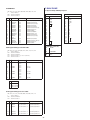
CONTENTS
INTRODUCTION ............................................................................................................ 5
PRECAUTIONS.............................................................................................................. 6
UPPER PANEL .............................................................................................................. 8
REAR PANEL............................................................................................................... 13
P-200 OVERVIEW........................................................................................................ 14
GETTING STARTED .................................................................................................... 18
Setting up the P-200....................................................................................................................... 18
Turning on the Power...................................................................................................................... 20
Playing the Demo Songs................................................................................................................. 21
Playing the Voices........................................................................................................................... 22
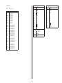
VOICE PLAY MODE ............................................................................................................ 23
Single Mode.................................................................................................................................... 24
Stereo/Mono Piano ......................................................................................................................... 25
Upright/Electric Bass....................................................................................................................... 25
Reverb Effects................................................................................................................................. 26
Modulation Effects .......................................................................................................................... 27
Panel Equalizer ............................................................................................................................... 29
Main and Sub Voices ...................................................................................................................... 29
Dual Mode ...................................................................................................................................... 30
Split Mode ...................................................................................................................................... 32
Transpose....................................................................................................................................... 37
MIDI Transmit Enable ...................................................................................................................... 40
MIDI Panic ...................................................................................................................................... 41
Panel Switch Lock .......................................................................................................................... 41
PERFORMANCE PLAY MODE ........................................................................................... 45
Selecting Single Voices ................................................................................................................... 46
Selecting Dual Voices...................................................................................................................... 47
Selecting Split Voices ...................................................................................................................... 47
EDIT MODE ......................................................................................................................... 49
System ........................................................................................................................................... 51
MIDI Filter........................................................................................................................................ 53
Program Change (PC) Table............................................................................................................ 53
Channel .......................................................................................................................................... 54
Local............................................................................................................................................... 55
Continuous Slider (CS) / Foot Controller (FC)................................................................................... 55
Panel Switch (PS)............................................................................................................................ 57
Name.............................................................................................................................................. 57
Organ Combination......................................................................................................................... 57
Pitch Bend Wheel (PB) / Modulation Wheel (MW) ............................................................................ 58
Keyboard Sensitivity........................................................................................................................ 58
Internal Equalizer............................................................................................................................. 59
Reverb ............................................................................................................................................ 59
Modulation ...................................................................................................................................... 59
STORE ................................................................................................................................. 60
APPENDIX ........................................................................................................................... 62
Bulk Dump.......................................................................................................................................62
Initialize ........................................................................................................................................... 63
Using MIDI ...................................................................................................................................... 64
Error Messages............................................................................................................................... 67
Troubleshooting .............................................................................................................................. 68
Specifications...................................................................................................................................70
Index................................................................................................................................................71
Factory Default Settings ...................................................................................................................72
Blank Chart ......................................................................................................................................78
MIDI Data Format.............................................................................................................................80
MIDI Implementation Chart...............................................................................................................89
The LCD screen displays as illustrated in this manual are for instructional purposes only, and may
appear somewhat different from your P-200’s.
7
P200_01.QX 98.4.21 4:58 PM ページ 8
UPPER PANEL
#
OUT
MIDI
IN
THRU
B
VOLUME
CS
CONTRAST
STORE
PERF. A
MIDI
EDIT
PERF. B
MAX
1
POWER
PS1
PS2
SPLIT
TRANSPOSE
BALANCE
DETUNE
VOICE
PIANO 1
2
PIANO 2
MIN
ON/
OFF
DATA ENTRY
PITCH
-1/NO
+1/YES
SYSTEM
PAGE
C3
MODULATION
A
!
"
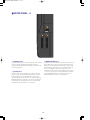
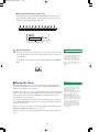
! [PHONES] jack
# Speakers
This jack on the front panel lets you connect a pair of stereo
headphones to the P-200 for private listening. The internal
speakers will automatically be disconnected when you plug in the
headphones. The sound of the internal voices output from the
[OUTPUT] jacks is not affected.
These two built-in 13 cm speakers each provide an output of 30
watts. If you connect the P-200 to an external monitor system, you
may choose to turn the speakers off using the [SPEAKER] switch
located on the rear panel.
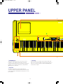
" Keyboard
This 88-key weighted action, touch-sensitive keyboard
incorporates Yamaha’s unique Graded Hammer Effect keyboard
technology, which gives it the genuine feel and response of a real
piano keyboard.
8
MIDI FILTE
P200_01.QX 98.4.21 4:58 PM ページ 9
#
OUT
MIDI
IN
FOOT CONTROLLER
THRU
SOFT
SOSTENUTO
SUSTAIN
L/MONO
OUTPUT
R
L/MONO
INPUT
R
OFF ON
SPEAKER
C
EFFECT
STORE
REVERB
1
EDIT
C3
EQUALIZER
PERF. A
PERF. B
VOICE
2
3
4
PIANO 1
PIANO 2
PIANO 3
PIANO 4
SYSTEM
MIDI FILTER
PC TABLE
CHANNEL
5
6
7
8
9
10
11
12
E.PIANO 1 E.PIANO 2 E.PIANO 3
VIBES
ORGAN 1
ORGAN 2
STRINGS
BASS
CS FC
NAME
ORGAN
COMBINATION
PB MW
KBD SENS.
INT.EQ
LOCAL
PS
MODULATION
ROOM
STAGE
CHORUS
SYMPHONIC
HALL
TREMOLO
LOW
MIDDLE
HIGH
"
9
ELECTRONIC PIANO P-200
P200_01.QX 98.4.21 4:58 PM ページ 10
■ UPPER PANEL—A
POWER
ON/
PITCH
OFF
MODULATION
! [POWER] switch
# [MODULATION] wheel
This switch turns the power on and off. When the power is turned
on, the mode and status designated when the power was
previously turned off will still be active (with the exception of Panel
Swicth Lock; page 41).
This wheel can be used in various ways. Normally you will use it to
apply a vibrato effect to the notes that you play, with increasing
intensity as you roll it upwards; the wheel remains at the specific
position that you set it when you let go of it. (In Dual mode, both
voices are modulated; in Split mode, only the main voice is
modulated. The vibrato effect cannot be applied to Piano voices 1
~ 4.) You can also assign it to control reverb depth or modulation
speed. When MIDI transmission is enabled, you can use it to
transmit modulation messages to other instruments.
" [PITCH] wheel
This wheel can be used to bend the pitch of the notes that you
play, up or down; the wheel automatically returns to the center
position when you release it. (In Dual mode, both voices are
affected; in Split mode, only the main voice is affected.) When the
MIDI Transmit Switch is enabled, you can use it to transmit pitch
bend messages to other instruments. You can assign the pitch
bend range to any value within a one-octave range.
10
P200_01.QX 98.4.21 4:58 PM ページ 11
■ UPPER PANEL— B
!
"
# $ % & (
CS
VOLUME
)
CONTRAST
MAX
PS1
PS2
-1/NO
+1/YES
SPLIT
TRANSPOSE
BALANCE
DETUNE
MIDI
MIN
DATA ENTRY
PAGE
C3
'
! [VOLUME] slider
& [TRANSPOSE, DETUNE, q] button
This slider adjusts the overall volume of sound output from the
internal speakers (or headphones, if connected) as well as the
sound output from the [OUTPUT] jacks on the rear panel. Moving
the slider upward increases volume level, while moving the slider
downward decreases volume level.
This is a multiple function button. As a [TRANSPOSE] button, you
can use it to set the keyboard transpose value for single as well as
both Dual voices or Split voices. As a [DETUNE] button, you can
use it to set the detune value for the two Dual voices, by holding it
and moving the [DATA ENTRY] slider ". As a [q] (cursor right)
button in Edit mode, you can use it to move the cursor to the right
in the LCD screen in order to position it over a desired parameter.
" [CS, DATA ENTRY] slider
This is a multiple function slider. As a [CS] (continuous slider), you
can assign it to control a variety of functions. As a [DATA ENTRY]
slider, you can use it to change specific settings and parameters,
depending on the current mode and status. Moving the slider
upward increases the specified value, while moving the slider
downward decreases the specified value.
' [MIDI, PAGE] button
This is a dual function button. As a [MIDI] transmit button, you can
use it to quickly enable or disable the P-200’s transmission of MIDI
messages. You can also hold the [MIDI] button while pressing
other buttons to access certain features. As a [PAGE] button, you
can use it to step through the various pages of Edit functions
when the P-200 is in Edit mode.
# [PS1, –1/NO] button
This is a dual function button. As a [PS1] (Panel Switch 1) button,
you can assign it to control various functions of the internal voices
as well as connected MIDI devices, as set by the PS Edit function.
As a [–1/NO] button, you can use it to change parameter settings
in decrements.
( [CONTRAST] dial
This dial lets you adjust the contrast of the LCD screen for
optimum visibility. Rotating it to the left will decrease screen
contrast, while rotating it to the right will increase screen contrast.
$ [PS2, +1/YES] button
) LCD screen
This is a dual function button. As a [PS2] (Panel Switch 2) button,
you can assign it to control various functions of the internal voices
as well as connected MIDI devices, as set by the PS Edit function.
As a [+1/YES] button, you can use it to change parameter settings
in increments.
This backlit 32-character Liquid Crystal Display screen provides
various information about the modes and operating status of the
P-200. Certain messages are displayed only temporarily, but you
can designate the “Popup Time” according to your preference.
% [SPLIT, BALANCE, 1] button
This is a multiple function button. As a [SPLIT] button, you can use
it to enter Split mode, whether in Voice Play or Performance Play
mode, determine the split point and assign the keyboard area for
the main and sub voices. As a [BALANCE] button, you can use it
to set the relative volume levels of each Split and Dual voice, by
holding the [BALANCE] button and moving the [DATA ENTRY]
slider ". As a [1] (cursor left) button in Edit mode, you can use it
to move the cursor to the left in the LCD screen in order to
position it over a desired parameter.
11
P200_01.QX 98.4.21 4:58 PM ページ 12
■ UPPER PANEL—C
!
# $
%
&
'
(
EFFECT
STORE
REVERB
EDIT
EQUALIZER
PERF. A
PERF. B
VOICE
1
2
3
4
PIANO 1
PIANO 2
PIANO 3
PIANO 4
SYSTEM
MIDI FILTER
PC TABLE
CHANNEL
8
9
10
11
12
E.PIANO 1 E.PIANO 2 E.PIANO 3
5
VIBES
ORGAN 1
ORGAN 2
STRINGS
BASS
CS FC
NAME
ORGAN
COMBINATION
PB MW
KBD SENS.
INT.EQ
LOCAL
6
7
PS
MODULATION
ROOM
STAGE
CHORUS
SYMPHONIC
HALL
TREMOLO
LOW
MIDDLE
HIGH
"
! [STORE] button
This button lets you store changes that you make to a
Performance, as well as copy the current Performance into any
Performance memory. The P-200 can store 24 Performances.
% [VOICE, PERFORMANCE, EDIT SELECT]
buttons
This button lets you enter Edit mode and access the various Edit
functions. After pressing it once, the LED above the [EDIT]
button will begin blinking, as will the light above the currently
selected [EDIT SELECT] button %. Pressing it again will return
you to the previous Play mode.
These 12 buttons each have multiple functions, depending on
the current mode. In Voice Play mode you can use them to
select any of the 12 preset AWM instrument voices you want to
play; the voice names are printed in above the buttons. In
Performance Play mode you can use them to select any of the
24 Performances (12 Performances per bank); the Performance
numbers are printed above the buttons. In Edit mode, you can
use them to select the Edit functions; the Edit function names
are printed in green below the buttons.
# [PERF. A, B] buttons
& [REVERB] button
These buttons let you enter Performance Play mode and select
any of the 24 Performances. The P-200 is set at the factory with
24 Preset Performances, but you can overwrite them and store
User Performances which you create yourself. The [PERF. A]
and [PERF. B] banks hold 12 Performances each, and a lit LED
above one of the buttons indicates the currently active bank.
This button lets you select either a Room, Stage or Hall reverb
effect, or no reverb effect, to apply to the currently selected
voice. Each voice has a default reverb setting preprogrammed at
the factory which you can change.
" [EDIT] button
$ [VOICE] button
This button lets you enter Voice Play mode by pressing [VOICE]
and then pressing a [VOICE SELECT] button %. A lit LED above
the [VOICE] button indicates you’re in Voice Play mode.
' [MODULATION] button
This button lets you select either a Chorus, Symphonic or
Tremolo modulation effect, or no modulation effect, to apply to
the currently selected voice. Each voice has a default modulation
setting preprogrammed at the factory which you can change.
( [EQUALIZER] sliders
These sliders let you graphically adjust the level of the sound
output of the P-200 in three bands: High, Middle and Low. In
Dual and Split modes, the changes you make will affect both
voices.
12
P200_01.QX 98.4.21 5:04 PM ページ 13
REAR PANEL
INPUT
SPEAKER
ON OFF
R
L/MONO
THRU
OUTPUT
R
L/MONO
SUSTAIN
SOSTENUTO
SOFT
MIDI
OUT
IN
FOOT CONTROLLER
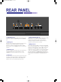
! [SPEAKER] switch
% [FOOT CONTROLLER] jack
This switch lets you turn off the P-200’s internal speakers. It does
not affect the output from the [OUTPUT] jacks or the [PHONES]
jack.
This jack lets you connect a foot controller (Yamaha FC7, available
separately) for use as an auxiliary controller. The [FC] foot
controller can be assigned to control a variety of functions,
including reverb depth or modulation speed, which lets you
change these parameters by foot as you play.
" [INPUT] jacks
These jacks let you input line-level signals from another electronic
instrument, such as a rhythm programmer, external tone
generator, or synthesizer, and monitor it through the P-200’s
internal speakers. Use the [L/MONO] jack when connecting only a
single line.
& [MIDI] terminals
These terminals allow the P-200 to communicate with other MIDI
devices, using standard MIDI cables. To control the P-200 using a
sequencer or another keyboard, connect the MIDI out jack of the
external device to the [MIDI IN] jack of the P-200. To control
another device (such as a synthesizer or tone generator) using the
P-200, connect the [MIDI OUT] jack of the P-200 to the MIDI in
jack of the external device. The [MIDI THRU] jack simply passes
the data received at the P-200’s [MIDI IN] jack through unaffected,
and is used when connecting three or more MIDI devices in a
series.
# [OUTPUT] jacks
These jacks output line-level signals which can be input directly to
an external amplifier, mixer or other audio device. Use the
[L/MONO] jack if your audio equipment has only one input.
$ Pedal jacks
These jacks let you connect up to three foot pedals and use them
as sustain, sostenuto and soft pedals. A single FC4 footswitch is
included with your P-200. If you wish to attach additional foot
pedals, be sure to use only Yamaha models FC4 or FC5.
13
P200_01.QX 98.4.21 5:05 PM ページ 14
P-200 OVERVIEW
The Yamaha P-200 is a versatile electronic piano with very high fidelity piano and other sounds and the
genuine touch and response of a real piano.
In its simplest form of use, all you really need to do is switch it on and start playing! However, this is just barely
scratching the surface, since the P-200 has powerful performance and MIDI master keyboard capabilities.
Below is an overview of the basic operating modes and the system structure of the P-200, with explanations of
how the various features relate to each other during practical use of the instrument.
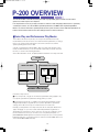
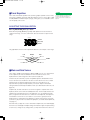
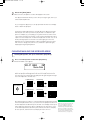
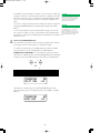
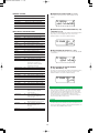
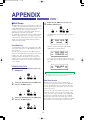
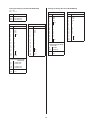
■ Voice Play and Performance Play Modes
The P-200 has two basic Play modes, Voice Play mode and Performance Play
mode. Within each mode are various Voice and Performance parameters, or settings
that you can change, which make up the sound of the selected voice and the
specific operating status of the P-200.
A group of overall System settings apply to both Voice Play and Performance Play
modes, and Edit mode lets you access and edit a wide variety of System and other
functions, as shown in the following illustration.
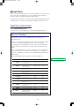
As the above illustration shows, the primary difference between Voice Play mode and
SYSTEM
VOICE PLAY MODE
PERFORMANCE PLAY MODE
PERF. A
01~12
VOICE 01~12
PERF. B
01~12
PERFORMANCE
PARAMETERS
VOICE
PARAMETERS
EDIT MODE / STORE FUNCTIONS
Performance Play mode is:
■ In Voice Play mode, a single set of Performance parameter settings apply to any
voice (and its specified Voice parameter settings) which you select.
■ In Performance Play mode, a complete set of Performance parameters can be
configured specifically for any particular voice (and its specified Voice parameter
settings). The P-200 can store up to 24 Performances for instant recall.
Normally you will operate in Voice Play mode, Auto Store status (See “About Store
Type”, next page)—as you select sounds and make parameter assignments as
dictated by your current music session. Then you can store those settings to any of
the 24 Performances, which you can then access at any time by the press of a
[PERFORMANCE SELECT] button in Performance Play mode. (You can also perform
bulk dump operations of Performance data to and from an external MIDI device such
as the Yamaha MDF3 MIDI Data Filer.)
14
P200_01.QX 98.4.22 5:44 PM ページ 15
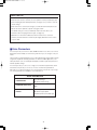
ABOUT STORE TYPE
You can choose the Store Type—Non Auto Store and Auto Store.
When Non Auto Store is selected, the store operation is always required (except
when modifying System related parameters; see page 17) if you want to save the
current settings.
When Auto Store is selected, all changes you make will automatically be stored
without the need to perform a specific storing procedure.
The default setting for a new (or initialized) P-200 is Non Auto Store. (For
information about changing the Store Type, see page 52.)
Explanations in this Owner’s Manual assume that Auto Store is selected.
Therefore, the LCD illustrations herein may be slightly different than the screens
on your P-200.
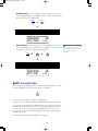
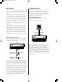
■ Voice Parameters
In Voice Play mode, each of the P-200’s AWM instrument voices have a set of Voice
parameters that are initially set at the factory, but which you can change to suit your
needs.
These include controller parameters such as pitch bend range and modulation wheel
assignment, keyboard sensitivity parameters for internal or MIDI applications, and
effect parameters such as reverb type and depth, modulation type and speed, and
internal equalizer settings.
In Voice Play mode you can access a single set of Performance parameters and in
Performance Play mode you can access 24 sets of Performance parameters.
Although you can freely change the voices in Performance Play mode, only a single
set of Voice parameters is available for each Performance.
VOICE PARAMETERS
CONTROLLERS
• Pitch Bend Range
• Modulation Wheel Assign
KEYBOARD SENSITIVITY
• Internal
• MIDI
EFFECT
• Reverb Type, Speed
• Modulation Type, Speed
• Equalizer (Internal) Low, Mid, High
15
P200_01.QX 98.4.21 5:05 PM ページ 16
■ Performance Parameters
In Performance Play mode, the P-200 has 24 sets of Performance parameters which
let you configure settings for specific music situations (i.e., for a certain style of
music, or a particular song, or for a practice session, or a live set, etc.). This affords
you the convenience of being able to recall those settings instantly at the press of a
button when in Performance Play mode.
Performance parameters include the voice selection (a set of voice parameters),
keyboard Single, Dual or Split mode and settings, main and sub voice assignments,
User organ combination values, transposition values, keyboard local on or off setting,
MIDI transmit and receive channel numbers, plus function assignments for [PS1],
[PS2], [CS] and [FC] (foot controller), the Performance name and others.
In Voice Play mode you can specify settings for a single set of Performance
parameters.
Performance Parameters
VOICE SELECT
12 voices
(A set of voice parameters)
KEYBOARD MODE
Single, Dual, Split
VOICE
Main, Sub
PIANO 1/2
Stereo, Mono
BASS
Upright, Electric
ORGAN COMBINATION
• Footage
• Response,
Attack (Length and Mode)
BALANCE
–16 ~ 15
DETUNE
0~7
SPLIT POINT
• A-1 ~ C7
• MAIN VOICE (Upper, Lower)
TRANSPOSE
• Enable Switch
• Internal Main, Sub
• MIDI Main, Sub
MIDI CHANNEL
• Transmit
• Receive
LOCAL
On, Off
CONTROLLERS
• PS 1/2 Assign
• CS Assign, Range
• FC Assign, Range
NAME
Character select
16
P200_01.QX 98.4.21 5:05 PM ページ 17
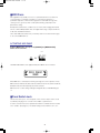
■ System Settings
The P-200’s overall System settings encompass those “global” parameters which are
related to the instrument as a whole, and which therefore affect both Voice Play and
Performance Play modes.
These include master tuning, MIDI transmit enable, MIDI filter transmit and receive
parameter settings, MIDI program change table settings, and others.
SYSTEM
MIDI TRANSMIT ENABLE
SYSTEM
On, Off
• Master Tune
• Reverb Bypass
• Device Number
• MIDI Merge
• Performance Enable
• Popup Time
• Store Type
• Panel Switch Lock Mode
MIDI FILTER
• Transmit
• Receive
PROGRAM CHANGE TABLE
• Transmit Number, Bank
Select Number
• Receive Number
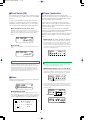
■ Editing and Storing Features
When the P-200 is in Edit mode, you can access and modify the System and other
parameters.
A convenient Auto Store feature (which you can disengage) automatically stores the
System settings and other parameters as you change them. Within either Voice Play
mode or Performance Play mode, you can store the current set of all settings as a
User Performance.
There is a fine distinction between Voice Play mode store and Performance Play
mode store functions. In Voice Play mode, you can overwrite the current set of Voice
and Performance parameter settings. In Performance Play mode, you can select a
specific destination Performance in which to store the current Performance
parameter settings. Therefore, if you select a destination Performance in which to
store the current Voice Play mode Performance parameter settings, you are storing it
in the Performance Play mode.
You will find it most convenient to set up your Performances in Voice Play mode,
Auto Store status, since voice selection is so simple, then copy it to one of the 24
Performance memories for instant recall when you need it.
By switching into Non Auto Store status, you can be sure that your Performances are
protected, and any changes you make in one will not be applied unless you
specifically store, or overwrite, it. In Edit mode, the P-200 will prompt you
automatically whether or not to overwrite the current changes.
You can also dump Performance data to and from external MIDI devices.
17
NOTE
Descriptions of all parameters and
details about how to access and
manipulate them are provided in the
appropriate sections herein. Also see
the Blank Chart on page 78.
P200_02.QX 98.4.21 5:07 PM ページ 18
GETTING STARTED
This section explains how to set up the P-200 and the proper procedure for turning it on, playing the
preprogrammed Demo songs, and basic voice selection.
■ Setting up the P-200
Although setting up the P-200 for basic play is easy and straightforward, be sure to
take heed of the Precautions on page 6 before you begin, then carefully follow the
simple steps as outlined below.
P-200 SETUP PROCEDURE
1.
Prepare a suitable location.
The P-200 is relatively small for an 88-key instrument, but it is very solidly built
and therefore quite heavy. First you’ll want to prepare a suitable location for
your P-200. Please do not hesitate to ask someone to help you take it out of
the box and carefully place it on an optionally available Yamaha LP-3 keyboard
stand or a sturdy table.
2.
Plug in the power cord.
Next plug the P-200’s power cord into an AC outlet. Do not turn on the
[POWER] switch until you have made all connections as described below.
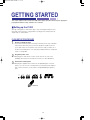
3.
Connect the sustain pedal.
Next plug the supplied FC4 footswitch into the [SUSTAIN] jack on the rear
panel, so you can use it as a sustain pedal. If you have purchased additional
FC4 or FC5 footswitches, connect them to the [SOSTENUTO] and [SOFT]
jacks.
INPUT
SPEAKER
ON OFF
R
L/MONO
THRU
OUTPUT
R
L/MONO
SUSTAIN
SOSTENUTO
SOFT
FOOT CONTROLLER
Footswitch FC4
18
MIDI
OUT
IN
P200_02.QX 98.4.21 5:07 PM ページ 19
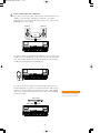
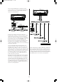
4.
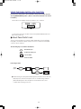
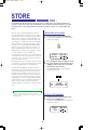
Connect external line-level components.
If you wish to monitor the P-200’s output using an external line-level mixer or
amplifier, connect the input of the external component to the P-200’s
[OUTPUT] jacks on the rear panel. (Use both jacks for stereo output; use the
[L/MONO] jack for mono output.)
Speaker (L)
Speaker (R)
Amp
OUTPUT L/MONO
OUTPUT R
OUT
MIDI
IN
FOOT CONTROLLER
THRU
SOFT
SUSTAIN
SOSTENUTO
R
L/MONO
OUTPUT
L/MONO
INPUT
R
OFF ON
SPEAKER
EFFECT
VOLUME
CS
CONTRAST
STORE
PERF. A
EDIT
PERF. B
MAX
REVERB
1
POWER
PS1
PS2
-1/NO
+1/YES
SPLIT
TRANSPOSE
BALANCE
DETUNE
MIDI
VOICE
2
3
PIANO 1
PIANO 2
PIANO 3
PIANO 4
SYSTEM
MIDI FILTER
PC TABLE
CHANNEL
4
5
6
7
8
E.PIANO 1 E.PIANO 2 E.PIANO 3
VIBES
CS FC
NAME
9
10
11
ORGAN 1
ORGAN 2
STRINGS
BASS
KBD SENS.
INT.EQ
12
EQUALIZER
MODULATION
ROOM
STAGE
CHORUS
SYMPHONIC
HALL
TREMOLO
MIN
ON/
OFF
DATA ENTRY
PITCH
LOCAL
PS
ORGAN
PB MIW
COMBINATION
C3
PAGE
LOW
MIDDLE
HIGH
MODULATION
P-200
If you wish to listen to your P-200 using headphones, connect a pair of stereo
headphones to the [PHONES] jack located on the left side of the front panel.
The P-200’s internal speakers will automatically be disconnected whenever
headphones are plugged into the [PHONES] jack.
OUT
MIDI
IN
FOOT CONTROLLER
THRU
SOFT
SOSTENUTO
SUSTAIN
L/MONO
OUTPUT
R
L/MONO
INPUT
R
OFF ON
SPEAKER
EFFECT
VOLUME
CS
CONTRAST
STORE
PERF. A
EDIT
PERF. B
MAX
REVERB
1
POWER
PS1
PS2
-1/NO
+1/YES
SPLIT
TRANSPOSE
BALANCE
DETUNE
MIDI
VOICE
2
3
PIANO 1
PIANO 2
PIANO 3
PIANO 4
SYSTEM
MIDI FILTER
PC TABLE
CHANNEL
4
5
6
7
8
E.PIANO 1 E.PIANO 2 E.PIANO 3
VIBES
CS FC
NAME
9
10
11
ORGAN 1
ORGAN 2
STRINGS
BASS
KBD SENS.
INT.EQ
12
EQUALIZER
MODULATION
ROOM
STAGE
CHORUS
SYMPHONIC
HALL
TREMOLO
MIN
ON/
OFF
DATA ENTRY
PITCH
LOCAL
PS
C3
PAGE
ORGAN
PB MIW
COMBINATION
LOW
MIDDLE
HIGH
MODULATION
P-200
If you wish to monitor the output of an external line-level device (such as a
rhythm programmer, tone generator or synthesizer) via the P-200’s internal
speakers, connect the output of the external device to the P-200’s [INPUT]
jacks on the rear panel. (Use both jacks for stereo input; use the [L/MONO]
jack for mono input.)
Tone Generator
INPUT L/MONO
INPUT R
OUT
MIDI
IN
FOOT CONTROLLER
THRU
SOFT
SOSTENUTO
SUSTAIN
L/MONO
OUTPUT
R
L/MONO
INPUT
R
OFF ON
SPEAKER
EFFECT
VOLUME
CS
CONTRAST
STORE
PERF. A
EDIT
PERF. B
MAX
REVERB
1
POWER
PS1
PS2
-1/NO
+1/YES
SPLIT
TRANSPOSE
BALANCE
DETUNE
MIDI
VOICE
2
3
PIANO 1
PIANO 2
PIANO 3
PIANO 4
SYSTEM
MIDI FILTER
PC TABLE
CHANNEL
4
5
6
7
8
E.PIANO 1 E.PIANO 2 E.PIANO 3
VIBES
CS FC
NAME
9
10
11
ORGAN 1
ORGAN 2
STRINGS
BASS
KBD SENS.
INT.EQ
12
EQUALIZER
MODULATION
ROOM
STAGE
CHORUS
SYMPHONIC
HALL
TREMOLO
MIN
ON/
OFF
DATA ENTRY
PITCH
PAGE
C3
LOCAL
PS
ORGAN
PB MIW
COMBINATION
LOW
MIDDLE
HIGH
MODULATION
P-200
19
CAUTION
Before connecting the P-200 to any
external device, be sure that the power
switches of all devices are turned off.
P200_02.QX 98.4.21 5:07 PM ページ 20
5.
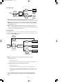
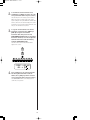
Connect MIDI devices.
If you wish to connect the P-200 to external MIDI devices such as a rhythm
programmer, tone generator or synthesizer, you will need special MIDI cables
which plug into the [MIDI] jacks on the rear panel. First, however, you must
determine a MIDI system configuration, based on your particular needs or
desires. Some examples of MIDI system connections, along with information
about MIDI, are provided on page 64.
MIDI Cable
MIDI OUT
MIDI IN
OUT
MIDI
IN
FOOT CONTROLLER
THRU
SOFT
SOSTENUTO
SUSTAIN
L/MONO
OUTPUT
R
L/MONO
INPUT
R
OFF ON
SPEAKER
EFFECT
VOLUME
CS
CONTRAST
STORE
PERF. A
EDIT
PERF. B
MAX
REVERB
1
POWER
PS1
PS2
-1/NO
+1/YES
SPLIT
TRANSPOSE
BALANCE
DETUNE
MIDI
VOICE
2
3
PIANO 1
PIANO 2
PIANO 3
PIANO 4
SYSTEM
MIDI FILTER
PC TABLE
CHANNEL
4
5
6
7
8
E.PIANO 1 E.PIANO 2 E.PIANO 3
VIBES
CS FC
NAME
9
10
11
ORGAN 1
ORGAN 2
STRINGS
BASS
KBD SENS.
INT.EQ
12
EQUALIZER
MODULATION
ROOM
STAGE
CHORUS
SYMPHONIC
HALL
TREMOLO
MIN
ON/
OFF
DATA ENTRY
PITCH
PAGE
LOCAL
C3
PS
ORGAN
PB MIW
COMBINATION
LOW
MIDDLE
HIGH
MODULATION
Sequencer
P-200
6.
Attach the music stand.
Finally, attach the supplied music stand to the P-200 by carefully inserting it
into the slots on the rear panel.
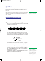
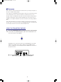
■ Turning on the Power
After setting up the P-200, you’re ready to turn on the power and begin enjoying the
instrument’s great sounds and many versatile performance and other features.
POWER
ON/
PITCH
OFF
MODULATION
Switch on the [POWER] button, then gradually raise the [VOLUME] slider until you
obtain a comfortable listening level.
CAUTION
VOLUME
MAX
Always turn the P-200 on first, and
then turn on external MIDI and audio
devices last. However, if a line-level
device is plugged into the P-200’s
[INPUT] jacks, turn it on before turning
on the P-200. When turning off the
power of each device, simply reverse
the process.
MIN
20
P200_02.QX 98.4.21 5:07 PM ページ 21
■ Playing the Demo Songs
After setting up the P-200 and turning on the power — and before you begin exploring
the instrument’s various features — you may want to listen to the various Demo songs,
which have been specially programmed to demonstrate the exceptional sound and
performance capabilities of the P-200. There are three main Demo songs, as well as
twelve special Voice Demo songs that showcase each voice.
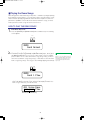
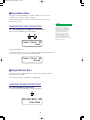
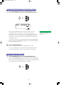
HOW TO PLAY THE DEMO SONGS
1.
Enter Demo Play mode.
Press the [REVERB] and [MODULATION] buttons simultaneously. The following
screen appears.
EFFECT
REVERB
MODULATION
ROOM
STAGE
CHORUS
SYMPHONIC
HALL
TREMOLO
DEMO
Song Select
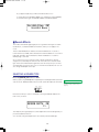
2.
● Selecting and playing a main Demo song:
Immediately after pressing [REVERB] and [MODULATION] (step 1, above), press
the [MODULATION] button once or more to select a Demo song. For example,
press the button once to select the first Demo song (“Song 1 Play”), or twice to
select the second Demo song (“Song 2 Play”), or three times to select the third
Demo song (“Song 3 Play”). The song you select will begin playing automatically.
EFFECT
REVERB
MODULATION
ROOM
STAGE
CHORUS
SYMPHONIC
HALL
TREMOLO
DEMO
Song 1 Play
If you press the [MODULATION] button four times, the message “All Voice
Demo” will appear in the LCD screen, and the P-200 will play all twelve voice
Demo songs continuously, one after the other.
All Voice Demo
********* Play
Voice name for current Demo song
21
NOTE
If you don’t press the [MODULATION]
button (or one of the [VOICE SELECT]
buttons) relatively quickly after having
entered the Demo Play mode, the P200 will automatically exit the Demo
Play mode.
P200_02.QX 98.4.21 5:07 PM ページ 22
● Selecting and playing a Voice Demo song:
Immediately after pressing [REVERB] and [MODULATION] (step 1, above),
press the [VOICE SELECT] button corresponding to the desired voice. The
selected song will begin playing automatically.
1
2
3
4
PIANO 1
PIANO 2
PIANO 3
PIANO 4
SYSTEM
MIDI FILTER
PC TABLE
CHANNEL
8
9
10
11
12
E.PIANO 1 E.PIANO 2 E.PIANO 3
5
VIBES
ORGAN 1
ORGAN 2
STRINGS
BASS
CS FC
NAME
KBD SENS.
INT.EQ
LOCAL
6
7
PS
ORGAN
PB MW
COMBINATION
DEMO
********* Play
Voice name for current Demo song
3.
Exit Demo Play mode.
If you select “Song 1 Play”, “Song 2 Play”, “Song 3 Play” or “All Voice Demo,”
the P-200 will exit the Demo Play mode automatically when the selected song
finishes playing.
To exit Demo Play mode while a song is playing, simply press the [REVERB]
button.
EFFECT
REVERB
NOTE
You cannot enter Demo Play mode (or
any other Play mode) when the P-200
is in Edit mode. (The LED above the
[EDIT] button will blink when the P-200
is in Edit mode.) To exit Edit mode,
simply press the [EDIT] button. Also
note that you will not be able to play
the P-200 or use any of the Edit mode
functions while a Demo song is
playing.
MODULATION
ROOM
STAGE
CHORUS
SYMPHONIC
HALL
TREMOLO
■ Playing the Voices
NOTE
Selecting and playing the voices of a new P-200 is simple, since by default the
instrument starts up for the first time in Voice Play mode with initialized parameter
settings, and the PIANO 1 voice selected.
Therefore, all you have to do is press a [VOICE SELECT] button and start playing the
keyboard. Take a few minutes and try playing each of the voices and notice the rich
quality and dimension of the P-200’s AWM sound, complete with the nuance of
natural expression via the keyboard.
As you play, try out the [PITCH] wheel, which lets you bend notes up or down. Also
try out the [MODULATION] wheel, which lets you add varying degrees of vibrato (or
other effects) to the voices.
While you’re at it, try out the various reverb and modulation effects, by pressing the
[REVERB] and [MODULATION] buttons once or more.
When you’re ready for more, turn the page, and find out about all the P-200 has in
store.
22
You can assign a specific effect to the
[MODULATION] wheel in Edit mode
(see page 58) which is completely
unrelated to the modulation effects
available by pressing the
[MODULATION] button (see page 27)
once or more. Note that when the
vibrato effect is assigned to the
[MODULATION] wheel, you cannot
apply vibrato modulation to the Piano
voices 1 ~ 4. Also note that the reverb
depth or modulation speed may be set
at 0 for certain voices, and therefore
produce no noticeable effect. (For
information about changing reverb
depth, see page 27. For information
about changing modulation speed,
see page 28.)
P200_03.QX 98.4.21 10:35 PM ページ 23
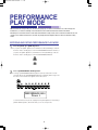
VOICE PLAY MODE
Voice Play mode consists of Single, Dual and Split modes. Within Voice Play mode you can select and play
any one of the 12 voices (Single mode), or play a blend of two voices simultaneously (Dual mode), or play one
voice on the left side of the keyboard and another on the right side of the keyboard (Split mode).
A brand new P-200 fresh out of the box will power on automatically in Voice Play Single mode, with the PIANO
1 voice selected.
If the P-200 is in Performance Play mode (indicated by a lit LED above the [PERF.A] or [PERF.B] button), you
will first need to press the [VOICE] button to enter Voice Play mode.
If the P-200 is in Edit mode (indicated by a blinking LED above the [EDIT] button), you will first need to exit Edit
mode by pressing the [EDIT] button.
ENTERING AND EXITING VOICE PLAY MODE
1.
Press the [VOICE] button.
When you press the [VOICE] button while the P-200 is in Performance Play
mode, the LED above the [VOICE] button starts blinking, indicating that Voice
Play mode is standing by waiting to be activated.
VOICE
2.
Press a [VOICE SELECT] button.
As soon as a [VOICE SELECT] button is pressed, Voice Play Single mode is
activated.
The LED above the [VOICE] button and the selected [VOICE SELECT] button
will light.
VOICE
1
2
3
4
PIANO 1
PIANO 2
PIANO 3
PIANO 4
SYSTEM
MIDI FILTER
PC TABLE
CHANNEL
5
6
7
8
E.PIANO 1 E.PIANO 2 E.PIANO 3
VIBES
OR
CS FC
NAME
O
COM
LOCAL
PS
9Ô VOICE 9
Ò
Piano 3
From within Single mode you can easily activate Dual mode (see page 30) or
Split mode (see page 32).
To exit Voice Play mode, simply enter Performance Play mode. For details, see
page 45.
23
P200_03.QX 98.4.21 10:35 PM ページ 24
■ Single Mode
When the P-200 is in Single mode, you can select and play any one of the 12 voices
over the full range of the keyboard. You can also apply and adjust reverb and
modulation effects, and adjust the graphic equalizer settings.
In Single mode, the LED above the currently selected [VOICE SELECT] button lights,
and the name of the currently selected Single voice appears in the LCD screen.
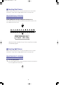
SELECTING A SINGLE VOICE
Press a [VOICE SELECT] button.
To select a voice you need only press any of the 12 [VOICE SELECT] buttons.
Voices and Polyphony
The P-200’s voices are high quality samples of real musical instruments
generated by Yamaha’s exclusive AWM (Advanced Wave Memory) tone
generation process.
All of the voices have 64-note polyphony, which means that a maximum number
of 64 notes can be played simultaneously. This is crucial for achieving
uncompromising sound and performance when using a sustain pedal, where
certain notes must hold over others as you play, until you release the sustain
pedal.
There is an extra dimension to some of the P-200’s voices. Two of the PIANO
voices have special stereo settings, which are capable of 32-note polyphonic
output. Also, the BASS voice has both acoustic UPRIGHT BASS and ELECTRIC
BASS settings.
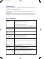
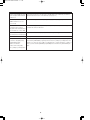
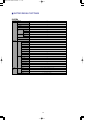
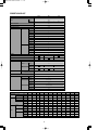
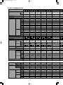
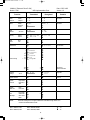
The following table provides an overview of each preset AWM voice.
NO.
VOICE
DESCRIPTION
SAMPLE TYPE
1
PIANO 1
Acoustic grand piano, suitable
for various types of music,
from classical to jazz.
Mono / Stereo
64 / 32
2
PIANO 2
Acoustic grand piano, with
sophisticated and deeper
resonance and body.
Mono / Stereo
64 / 32
3
PIANO 3
Bright acoustic grand piano,
ideal for rock as well as jazz.
Mono
64
4
PIANO 4
Bright electric grand piano,
ideal for pop ballads.
Mono
64
5
E. PIANO 1
Standard electric piano
with a sharp attack sound.
Mono
64
6
E. PIANO 2
Conventional, all-purpose
electric piano sound.
Mono
64
7
E. PIANO 3
Bright and sparkling,
DX-type electric piano sound.
Mono
64
8
VIBES
Full-bodied vibraphones
with sharp attack.
Mono
32 (2 layered)
9
ORGAN 1
Full-set organ combination sound
with editable footage lengths
and other parameters.
Mono
16
10
11
ORGAN 2
STRINGS
Mono
Mono
64
64
12
BASS
Mono
64
Standard jazz organ sound.
Full orchestral string ensemble.
Full-bodied, resonating
Upright Bass, and deep
Electric Bass with punch.
24
POLYPHONY
NOTE
The Organ 1 voice can be edited and
reconfigured in Edit mode (see page
57).
P200_03.QX 98.4.21 10:35 PM ページ 25
■ Stereo/Mono Piano
Pressing and holding the [PIANO 1] (or [PIANO 2]) button for a few moments
alternately selects the stereo and mono settings.
The initial default setting for the PIANO 1 (and PIANO 2) voice is stereo, and
polyphony is 32 notes.
NOTE
CHANGING THE PIANO VOICE SETTING
Press and hold [PIANO 1] (or [PIANO 2]) for a few moments.
After a moment, the MONO screen briefly appears.
1
2
PIANO 1
PIANO 2
or
SYSTEM
MIDI FILTER
Piano1 32/64 $
mono As you play the keyboard, the output of the PIANO 1 voice will be in mono, and
polyphony will be 64 notes.
To return the PIANO 1 voice to its stereo setting, simply press and hold [PIANO 1] for
a few moments again. The STEREO screen briefly appears.
Piano1 32/64 $
stereo ■ Upright/Electric Bass
Pressing and holding the [BASS] button for a few moments alternately selects the
Upright and Electric settings.
The initial default setting for the BASS voice is Upright Bass.
CHANGING THE BASS VOICE SETTING
Press and hold [BASS] for a few moments.
After a moment, the ELECTRIC BASS screen briefly appears.
12
BASS
INT.EQ
Upright/Elec. $
Elec.Bass 25
Once you have modified certain
parameters in Voice Play or
Performance Play mode, $ (Quick
Edit) will display in the upper right
corner to remind you that you have
modified the original settings.
Parameters include the following:
reverb and modulation setting,
stereo/mono setting for Piano1 and
Piano2, electric/upright setting for
Bass, plus Balance, Dual Detune, Split,
and Transpose settings.
P200_03.QX 98.4.21 10:35 PM ページ 26
As you play the keyboard, you will hear the Electric Bass voice.
To change back to the UPRIGHT BASS voice, simply press and hold [BASS]
for a few moments again. The UPRIGHT BASS screen briefly appears.
Upright/Elec. $
Upright Bass ■ Reverb Effects
The P-200’s internal DSP digital signal processor generates three types of realistic
reverb effects, or simulated ambient environments, which you can apply to the
voices.
These include ROOM, which simulates the natural reverberations of sound in a
normal-sized room, STAGE, which simulates the natural reverberations of sound in a
night club, and HALL, which simulates the natural reverberations of sound in a
relatively large concert hall.
As you select each voice you will notice that a specific reverb effect is already
assigned to it, indicated by a lit LED to the left of the name of the selected reverb
type. These are the initial default assignments set at the factory, but you can select
any reverb effect you wish for each voice, or even turn the reverb effect off. You can
also change reverb depth on the spot.
SELECTING A REVERB TYPE
Press the [REVERB] button once or more.
When you press the [REVERB] button repeatedly, the reverb types will be selected in
order as follows: ROOM, STAGE, HALL, then OFF. (No lit LED represents Off status.)
EFFECT
REVERB
MODULATION
ROOM
STAGE
CHORUS
SYMPHONIC
HALL
TREMOLO
NOTE
You can also select the reverb type
and depth settings in Edit mode (see
page 59).
Note that each time you select a reverb type, a message will briefly display in the
LCD screen, as follows.
REVERB DEPTH
$
2ÄÄ This temporary message displays the current depth level for the reverb type that you
just selected, between 0 and 7.
You can easily change the depth level for the currently selected reverb type.
26
P200_03.QX 98.4.21 10:35 PM ページ 27
CHANGING REVERB DEPTH
1.
Hold the [REVERB] button and move the [DATA ENTRY] slider (or press
[–1/NO] or [+1/YES]).
As soon as you move the [DATA ENTRY] slider (or press [–1/NO] or [+1/YES])
the REVERB DEPTH screen appears.
EFFECT
REVERB
MODULATION
ROOM
STAGE
CHORUS
SYMPHONIC
HALL
TREMOLO
CS
+
PS1
PS2
-1/NO
+1/YES
or
DATA ENTRY
If you move the [DATA ENTRY] slider upward, the depth level increases; if you
move the [DATA ENTRY] slider downward, the depth level decreases.
A value of 7 will produce the largest number of reverberations, whereas a value
of 0 will effectively turn the reverb off.
2.
Release the [REVERB] button.
After a moment, the voice name will reappear in the screen.
Try different settings and play the keyboard and notice the difference between
high and low reverb depth level settings, and the P-200’s wide variety of reverb
options.
NOTE
In Voice Play mode, a different reverb
type and depth can be selected for
each voice. When you play two voices
in either Dual or Split mode, the P-200
will apply the main voice reverb type
and depth setting to both voices, and
ignore any settings which you may
have made for the sub voice. For more
information about main and sub
voices, see page 29.
■ Modulation Effects
The P-200’s internal DSP digital signal processor generates three types of
modulation effects which you can apply to the voices. (Note: These modulation
effects are unrelated to the vibrato effect which you can apply to voices using the
[MODULATION] wheel. For details about the vibrato effect, see page 59.)
These include CHORUS, a modulated delay which effectively makes a voice sound
like more than one instrument is being played, SYMPHONIC, a more pronounced
chorus effect, and TREMOLO, a rotating speaker effect.
As you select each voice you will notice that most have a specific modulation effect
already assigned to them, indicated by a lit LED to the left of the name of the
selected modulation effect type. These are the initial default assignments set at the
factory, but you can select any modulation effect you wish for each voice, or even
turn the modulation effect off. You can also change modulation speed on the spot.
SELECTING A MODULATION TYPE
Press the [MODULATION] button once or more.
When you press the [MODULATION] button repeatedly, the modulation types will be
selected in order as follows: CHORUS, SYMPHONIC, TREMOLO, then OFF. (No lit
LED represents Off status.)
EFFECT
REVERB
MODULATION
ROOM
STAGE
CHORUS
SYMPHONIC
HALL
TREMOLO
27
NOTE
You can also select the modulation
type and speed settings in Edit mode
(see page 59).
P200_03.QX 98.4.21 10:35 PM ページ 28
Note that each time you select a modulation type, a message will briefly display
in the LCD screen, as follows.
MOD SPEED
$
3à This temporary message displays the current speed level for the modulation
type that you just selected, between 0 and 7. You can easily change the speed
level for the currently selected modulation type.
CHANGING MODULATION SPEED
1.
Hold the [MODULATION] button and move the [DATA ENTRY] slider (or
press [–1/NO] or [+1/YES]).
As soon as you move the [DATA ENTRY] slider (or press [–1/NO] or [+1/YES])
the MODULATION SPEED screen appears.
EFFECT
REVERB
MODULATION
ROOM
STAGE
CHORUS
SYMPHONIC
HALL
TREMOLO
CS
+
PS1
PS2
-1/NO
+1/YES
or
DATA ENTRY
If you move the [DATA ENTRY] slider upward, the speed level increases; if you
move the [DATA ENTRY] slider downward, the speed level decreases. A value
of 7 will produce the largest number of modulations, whereas a value of 0 will
effectively turn the modulation off.
2.
Release the [MODULATION] button.
After a moment, the voice name will reappear in the screen.
Try different settings and play the keyboard and notice the difference between
high and low modulation speed level settings.
28
NOTE
A different modulation type and speed
can be selected for each voice. When
you play two voices in either Dual or
Split mode, the P-200 will apply the
main voice modulation type and speed
setting to both voices, and ignore any
settings which you may have made for
the sub voice. For more information
about main and sub voices, see page
29.
P200_03.QX 98.4.21 10:35 PM ページ 29
■ Panel Equalizer
NOTE
The P-200’s three-band equalizer works just like a graphic equalizer found on many
home stereo amplifiers. The three sliders provide direct access to the P-200’s output
in LOW, MIDDLE and HIGH frequency ranges, which gives you considerable control
over the quality of the sound.
ADJUSTING THE EQUALIZATION
Move an [EQUALIZER] slider up or down.
Move either the [LOW], [MIDDLE] or [HIGH] slider upward to increase the level of
output for that range, or move it downward to decrease the level of output for that
range.
EQUALIZER
maximum
flat (normal)
minimum
LOW
MIDDLE
HIGH
The graph below shows how the equalizer modifies the sound output of each range.
LOW
MIDDLE
HIGH
NORMAL
■ Main and Sub Voices
The P-200 is capable of generating two different AWM voices at once, either in Dual
mode or Split mode. These are divided into main and sub voice areas of the
keyboard which can be assigned to either end of the keyboard.
In Dual mode, the order that you press the [SELECT] buttons will determine which
voice is the main voice and which is the sub voice. Since both voices are sounded
simultaneously, the distinction between the main voice and sub voice is not
important when you play the keyboard, but you’ll need to keep it in mind when
setting the detune relationship and balance levels. (For details about Dual mode, see
page 30.)
In Split mode, the main and sub voices each are assigned to separate areas of the
keyboard, known as the main and sub keyboard areas. The two keyboard areas are
separated at a specified key known as the split point. You can determine the split
point, assign the main and sub voices to either end of the keyboard, and adjust the
volume balance of the two voices in relation to each other. In general, the main
keyboard area is normally above the split point; however, there may be cases when
you’ll want to play the main voice below the split point. (For details about Split mode,
see page 32.)
Note that when you play two voices in either Dual or Split mode, the P-200 will apply
the main voice reverb type and depth setting and modulation type and speed setting
to both voices, and ignore any settings which you may have made for the sub voice.
29
An Internal Equalizer accessible in Edit
mode lets you adjust the frequency
ranges for each voice. For details, see
page 59.
P200_03.QX 98.4.21 10:35 PM ページ 30
■ Dual Mode
When the P-200 is in Dual mode, you can play two voices at the same time—a main
voice and a sub voice—over the full range of the keyboard. For example, you can
blend electric piano and strings sounds together to add depth and texture to a
melody line.
You can adjust the volume balance of the Dual voices in relation to each other, as
well as detune the voices in order to enrich the sound by bringing out the individual
characteristics of each Dual voice. You can also transpose each Dual voice (for
details, see page 39).
NOTE
In Dual mode you cannot select the
Organ 1 voice.
ENTERING AND EXITING DUAL MODE
1.
2.
Main Voice: Press and hold a [VOICE SELECT] button.
Sub Voice: While still holding the first button, simply press another
[VOICE SELECT] button.
The LED above each [VOICE SELECT] button lights, and those two voices will
sound when you play the keyboard.
1
2
3
4
PIANO 1
PIANO 2
PIANO 3
PIANO 4
SYSTEM
MIDI FILTER
PC TABLE
CHANNEL
8
9
10
11
12
E.PIANO 1 E.PIANO 2 E.PIANO 3
5
VIBES
ORGAN 1
ORGAN 2
STRINGS
BASS
CS FC
NAME
KBD SENS.
INT.EQ
LOCAL
6
7
PS
ORGAN
PB MW
COMBINATION
!
"
The order that you press the buttons will determine which voice is the main
voice and which voice is the sub voice. For example, if you press and hold [E.
PIANO 3] and then press [STRINGS], the ELECTRIC PIANO 3 voice will be the
main voice, and the STRINGS voice will be the sub voice.
9Ô VOICE Ò
E.P.3 +Strings
Main Voice
Sub Voice
In Dual mode, since both voices are sounded simultaneously, the distinction
between the main voice and sub voice is not important when you play the
keyboard. However, you will want to keep it in mind when adjusting the voice
balance and detune settings, as described below.
When you select voices in Dual mode, the P-200 will apply the main voice
reverb type and depth setting and modulation type and speed setting to both
voices, and ignore any settings which you may have made for the sub voice.
Also, [PITCH] and [MODULATION] wheels apply to both voices equally, with
the values as set for the main voice.
To exit Dual mode, simply press a single [VOICE SELECT] button to return to
Single mode, or press [SPLIT] and enter Split mode.
30
NOTE
In Dual mode, voice polyphony is
determined by the voices you select.
For example, if you select two 64-note
polyphonic voices, polyphony will be
reduced to 32 notes. If you select a
64-note voice and a 32-note (stereo)
voice, polyphony will be reduced to 21
notes. Likewise, if you select two 32note (stereo) voices, polyphony will be
reduced to 16 notes.
P200_03.QX 98.4.21 10:35 PM ページ 31
ADJUSTING THE BALANCE OF THE DUAL VOICES
1.
Hold the [BALANCE] button and move the [DATA ENTRY] slider.
As you move the [DATA ENTRY] slider, the DUAL BALANCE screen appears.
CS
SPLIT
BALANCE
+
DATA ENTRY
DUAL
BALANCE $
0J Sub Main
Moving the slider upwards increases the level of the main voice while
decreasing the level of the sub voice. Conversely, moving the slider
downwards increases the level of the sub voice while decreasing the level of
the main voice. You can set the balance to any value between -16 and 15.
Two indicators to the right of the numeric value display the relative balance of
sub and main voices.
You’ll find it convenient to set the desired balance by holding the [BALANCE]
button and moving the [DATA ENTRY] slider with one hand, and then playing
the keyboard with the other hand.
2.
Release the [BALANCE] button.
After a moment, the Dual voice names will reappear in the screen.
If you choose different Dual voices, the balance relationship will remain the
same as determined above, until you change the balance setting again.
DETUNING THE DUAL VOICES
1.
Hold the [DETUNE] button and move the [DATA ENTRY] slider.
As you hold the [DETUNE] button, do not press a key on the keyboard until
you move the [DATA ENTRY] slider. (Note: If you press a key on the keyboard
before moving the [DATA ENTRY] slider, you will change the Transpose setting.
For information about the Transpose feature, see page 37.)
CS
TRANSPOSE
DETUNE
+
DATA ENTRY
31
NOTE
In this case you cannot use the
[–1/NO] and [+1/YES] buttons to
change data.
P200_03.QX 98.4.21 10:35 PM ページ 32
As you move the [DATA ENTRY] slider, the DUAL DETUNE screen appears.
DUAL DETUNE 4^ $
You can set the detune to any value between 0 (no detuning) and 7 (maximum
detuning). Moving the slider upwards increases the detune value. Conversely,
moving the slider downwards decreases the detune value.
2.
Release the [DETUNE] button.
After a moment, the Dual voice names will reappear in the screen.
If you select different Dual voices, the detune relationship will remain the same
as determined above, until you change the detune setting again.
● Main and Sub Voice Detune Relationship
When you detune two voices in Dual mode, the main voice is raised above the
keyboard’s standard pitch by a certain amount and the sub voice is lowered below
the keyboard’s standard pitch by an equal amount. The result is that the individual
characteristics of each Dual voice are emphasized. The amount of pitch adjustment
depends on the value you select. At the maximum detune setting, the voices are
each detuned by about one-third of a semitone.
■ Split Mode
When the P-200 is in Split mode, you can play two voices at the same time—one
voice on the left side of the keyboard, and another voice on the right side of the
keyboard. For example, you can play a strings pad with one hand, while playing a
piano melody with the other; or you can play an upright bass line with your left hand,
while playing an organ riff with your right hand.
The two voices you play in Split mode are referred to as the main and sub voices.
These voices are assigned to separate areas of the keyboard, known as the main
and sub keyboard areas, which are separated at a specific key known as the split
point.
You can determine the split point and assign the main and sub voices to either end
of the keyboard. You can also adjust the volume balance of the two voices in relation
to each other (for details, see page 34.)
32
NOTE
In this case you cannot use the
[–1/NO] and [+1/YES] buttons to
change data.
P200_03.QX 98.4.21 10:35 PM ページ 33
ENTERING AND EXITING SPLIT MODE
Press the [SPLIT] button.
When you press the [SPLIT] button, the LED above it will light, and the keyboard will
split into two areas, one playing the main voice you selected in Single or Dual mode,
and the other playing the voice which was last selected as the Split mode sub voice.
(UPRIGHT BASS is the default sub voice designated at the factory.)
SPLIT
BALANCE
The current split point designation and keyboard area assignments briefly
appear in the screen.
Current split point
SPLIT POINT=C 2 KBD AREA=Sub/Man
Left side
Right side
The first line of the above screen indicates that the current split point area is
designated at key C2 (the initial default setting). The second line indicates that
the sub voice is assigned to the left side of the split point, while the main voice
is assigned to the right side of the split point.
After a few moments, the names of two voices will appear in the LCD screen.
9Ô VOICE Ò
Bass / Piano1
Sub Voice
Main Voice
The P-200 will now play the two voices using the current split point designation
and keyboard area assignments.
Split Point (included in main area)
Sub Voice
(C2)
Main Voice
NOTE
To exit Split mode, simply press the [SPLIT] button again. The P-200 will return
to Single or Dual mode, depending on which one was active before you
entered Split mode, playing the voice you have selected as the main voice.
If you enter Split mode directly from
Dual mode, and then choose the
Organ 1 voice as the main voice, when
you press the [SPLIT] button to exit
Split mode, the P-200 will
automatically switch to Single mode.
NOTE
In Split mode, the [PITCH] and
[MODULATION] wheels, as well as the
sustain, soft and sostenuto pedals, will
only affect the main voice.
33
P200_03.QX 98.4.21 10:35 PM ページ 34
SELECTING SPLIT VOICES
Main Voice: Press a [VOICE SELECT] button.
When you press the [SPLIT] button to enter Split mode, the voice you were
playing in Single mode (or the main voice you were playing in Dual mode) will
be assigned by default to the main keyboard area.
1.
To change the main voice, simply press any [VOICE SELECT] button, the same
as you would in Single mode.
1
2
3
4
PIANO 1
PIANO 2
PIANO 3
PIANO 4
SYSTEM
MIDI FILTER
PC TABLE
CHANNEL
8
9
10
11
12
E.PIANO 1 E.PIANO 2 E.PIANO 3
5
6
VIBES
ORGAN 1
ORGAN 2
STRINGS
BASS
CS FC
NAME
KBD SENS.
INT.EQ
LOCAL
7
PS
ORGAN
PB MW
COMBINATION
Sub Voice: Hold the [SPLIT] button and press a [VOICE SELECT] button.
Note that you can assign the same voice to both main and sub keyboard
areas. This is useful in such cases where you want to use the same voice on
each end of the keyboard, but with different Transpose settings (for details, see
page 37), or at different volume balance levels.
2.
SPLIT
BALANCE
+
1
2
3
4
PIANO 1
PIANO 2
PIANO 3
PIANO 4
SYSTEM
MIDI FILTER
PC TABLE
CHANNEL
5
8
9
10
11
12
E.PIANO 1 E.PIANO 2 E.PIANO 3
VIBES
ORGAN 1
ORGAN 2
STRINGS
BASS
CS FC
NAME
KBD SENS.
INT.EQ
LOCAL
6
7
PS
ORGAN
PB MW
COMBINATION
You’ll find it convenient that the procedure for selecting voices is separate from
that for entering and leaving Split mode, since this lets you switch the sub
keyboard area on and off as needed. For example, you can play the main voice
in Single Play mode (or Dual voices) across the entire keyboard during a song’s
verse and chorus, then switch into Split mode to add the sub voice for an
intricate two-part solo, then switch the Split mode off to play remaining verses
and choruses.
ADJUSTING THE BALANCE OF THE SPLIT VOICES
1.
Hold the [BALANCE] button and move the [DATA ENTRY] slider.
As you move the [DATA ENTRY] slider, the SPLIT BALANCE screen appears.
CS
SPLIT
BALANCE
+
DATA ENTRY
SPLIT BALANCE $
J0 Sub Main
34
P200_03.QX 98.4.21 10:35 PM ページ 35
Moving the slider upwards increases the level of the main voice while decreasing the
level of the sub voice. Conversely, moving the slider downwards increases the level
of the sub voice while decreasing the level of the main voice. You can set the balance
to any value between -16 and 15. Two indicators to the right of the numeric value
display the relative balance of sub and main voices.
2.
Release the [BALANCE] button.
After a moment, the Split voice names will reappear in the screen.
If you choose different Split voices, the balance relationship will remain the
same as determined above, until you change the balance setting again.
CHANGING THE SPLIT POINT
1.
Hold the [SPLIT] button and press a key on the keyboard.
The key that you press will become the new split point. The SPLIT POINT
screen appears.
SPLIT
BALANCE
+
(G3)
SPLIT POINT
$
G 3 As long as you hold the [SPLIT] button, the note name of the key that you
pressed will blink; pressing another key will change the split point still again,
and the name of the new split point will likewise appear in the screen.
You can also raise or lower the current split point setting one semitone at a
time by holding the [SPLIT] button and pressing the [–1/NO] or [+1/YES]
buttons.
35
NOTE
In this case you cannot use the
[–1/NO] and [+1/YES] buttons to
change data.
P200_03.QX 98.4.21 10:35 PM ページ 36
2.
Release the [SPLIT] button.
After a moment, the Split voice names will reappear in the screen.
The split point will remain where you set it until you change it again, even if you
exit and reenter Split mode.
As you change the split point you can specify whether the main voice will play
above or below the split point.
In general, the main keyboard area is normally above the split point; however,
there may be cases when you’ll want to play the main voice below the split
point. For example, say you’re playing a song where the verses and choruses
call for a piano in the bass and strings on top, and an instrumental part calls for
a piano solo that sweeps from one end of the keyboard to another. You can do
this by selecting the piano as the main voice and assigning it to the lower
keyboard area. You will then be able to switch from Split mode for the verses
and choruses to Single mode form the solo, then back to split mode again,
simply by pressing the [SPLIT] button.
CHANGING MAIN AND SUB KEYBOARD AREAS
Hold the [SPLIT] button, then press and hold the split point key.
1.
2.
Press a second key below or above the split point key.
The SPLIT AREA screen appears.
SPLIT AREA
$
Main/Sub As you hold the [SPLIT] button and split point key, pressing a second key
below the split point will designate the left area of the keyboard as the main
area. Pressing a second key above the split point will again designate the right
area of the keyboard as the main area.
C3 (Split point key)
D3 (Select key)
+
+
Press and hold
Press and hold
Select upper key
Sub
Main
SPLIT
B2 (Select key)
C3 (Split point key)
BALANCE
+
+
Press and hold
Select lower key
Main
Sub
Note that the key that you press to select the split point will always be included
in the main keyboard area. Thus, if you select F4 as the split point and then set
the main keyboard area below this point, the main voice will play all notes up to
and including F4, whereas the sub voice will play all notes from F#4 on. If you
set the main keyboard area above this point, however, the sub voice will play
all notes up to E4, and the main voice will play all notes from F4 on.
36
NOTE
When you select voices in Split mode,
the P-200 will apply the main voice
reverb type and depth setting and
modulation type and speed setting to
both voices, and ignore any settings
which you may have made for the sub
voice. (For more information about
main and sub voices, see page 29.)
P200_03.QX 98.4.21 10:35 PM ページ 37
■ Transpose
The P-200 has a multi-faceted transpose feature that lets you transpose the pitch at
the touch of a button while you play.
The P-200 has four independent transpose paths, which let you set transpose values
for the internal main voice as well as the sub voice, and which also let you set
transpose values for the MIDI main and sub voices which will affect external devices.
Transpose is particularly useful in the Dual and Split modes. In the Dual mode, for
example, you can play two different voices at the same time, each having a different
pitch.
The P-200’s default main voice transpose setting is 12, which means the pitch will
transpose up one octave when you press the [TRANSPOSE] button. The default sub
voice transpose amounts are set to 0 for Dual and Split modes.
USING THE TRANSPOSE FEATURE
1.
Press the [TRANSPOSE] button to transpose the pitch of the keyboard.
The LED above the [TRANSPOSE] button lights and the TRANSPOSE screen
with current transpose value appears.
TRANSPOSE
DETUNE
Depending on the current status and mode, the TRANSPOSE screen will be
different. For example, if the P-200 is in Split mode and the MIDI transmit
switch is enabled, the screen will display internal and MIDI main and sub voice
transposition values.
Main voice internal transposition
Main voice MIDI transposition
Sub voice MIDI transposition
Sub voice internal transposition
37
P200_03.QX 98.4.21 10:35 PM ページ 38
As you play in Split mode, the pitch of both voices will transpose according to
main and sub voice settings when you press the [TRANSPOSE] button. You
can play two-handed duets with different instruments by transposing the sub
voice up or down two octaves to match the pitch range of the main voice.
If the P-200 is in Dual mode and the MIDI transmit switch is enabled, the
TRANSPOSE screen will display internal and MIDI main voice and internal sub
voice transposition values.
As you play in Dual mode, the pitch of both voices will transpose according to
independent main and sub voice settings when you press the [TRANSPOSE]
button. Thus, you can create two-note harmonies by lowering the sub voice so
that it plays a fifth or an octave below the main voice.
If the P-200 is in Single mode and the MIDI transmit switch is enabled, the
TRANSPOSE screen will display internal and MIDI main voice transposition
values.
As you play in Single mode, the pitch of the entire keyboard will transpose
according to the main voice setting when you press the [TRANSPOSE] button.
(The sub voice is not active in Single mode.)
If the MIDI transmit switch is disabled, only the main voice (and sub voice,
depending on mode) transposition value will be displayed.
2.
Press the [TRANSPOSE] button again to return the keyboard to normal
pitch.
The LED above the [TRANSPOSE] button goes out and the keyboard returns
to normal pitch.
SETTING THE TRANSPOSE AMOUNT
1.
When the transpose function is on, hold the [TRANSPOSE] button and
press a key on the keyboard.
The key that you press becomes the new transpose amount. The
TRANSPOSE screen appears.
TRANSPOSE
DETUNE
+
TRANSPOSE
MAIN
$
+12 38
P200_03.QX 98.4.21 10:35 PM ページ 39
C3 (middle C) is the normal pitch, or 0 value, so all you need to do is press any
key above or below C3 to set the transpose amount. For example, if you want
the transpose amount to be one octave below normal keyboard pitch, simply
press C2. To return the transpose amount to normal pitch, simply press C3
again.
You can also change the transpose amount setting one semitone at a time by
holding the [TRANSPOSE] button and pressing the [–1/NO] and [+1/YES]
buttons.
You can set the transpose amount anywhere within a range of four octaves,
from -24 (C1) to 24 (C5). If you try to set the transpose amount by pressing a
key below C1 or above C5 on the keyboard, the P-200 will react as though you
pressed C1 or C5.
2.
Release the [TRANSPOSE] button.
The P-200 will assume that you want to transpose using this value, and leave
the transpose function turned on after you complete the setting.
In a similar way, internal sub voice and MIDI transpose signals for the MIDI
main and sub voice can be set independently, as explained below.
INTERNAL SPLIT SUB VOICE: To set the transpose value for the internal
split sub voice, in Split mode, press and hold [TRANSPOSE], then hold [SPLIT],
then press a key on the keyboard (or press the [–1/NO] or [+1/YES] buttons).
!
TRANSPOSE
DETUNE
+
+
"
SPLIT
BALANCE
#
TRANSPOSE
SPLIT SUB
$
+12 INTERNAL DUAL SUB VOICE: To set the transpose value for the internal
dual sub voice, in Dual mode, press and hold [TRANSPOSE], then hold
[SPLIT], then press a key on the keyboard (or press the [–1/NO] or [+1/YES]
buttons).
TRANSPOSE
DUAL SUB
$
+12 39
NOTE
In this case you cannot use the [CS]
slider to change the transpose value.
(Trying to do so in Dual mode will
activate the detune function.)
NOTE
When the transpose setting exceeds
the legal range (A–1 ~ C7) the P-200
plays and repeats the one octave
higher (or lower) range. Also note that
MIDI notes will not be transmitted if the
data exceeds MIDI note values 0 ~
127.
P200_03.QX 98.4.21 10:35 PM ページ 40
MIDI MAIN VOICE: To set the transpose value for the MIDI main voice, press
and hold [TRANSPOSE], then hold [MIDI], then press a key on the keyboard (or
press the [ –1/NO] or [+1/YES] buttons).
!
TRANSPOSE
DETUNE
+
+
"
MIDI
PAGE
#
TRANSPOSE
MIDI MAIN
$
+12 MIDI SUB VOICE: To set the transpose value for the MIDI sub voice, press
and hold [TRANSPOSE], followed by [SPLIT], then [MIDI], then press a key on
the keyboard (or press the [–1/NO] or [+1/YES] buttons).
!
TRANSPOSE
DETUNE
+
"
SPLIT
BALANCE
+
#
MIDI
PAGE
+
TRANSPOSE
MIDI SUB
$
$
+12 ■ MIDI Transmit Enable
You can enable or disable MIDI transmission by pressing the [MIDI] button. The LED
above the [MIDI] button remains lit while this function is enabled.
MIDI
PAGE
It will not block the reception of data from the [MIDI IN] jack.
Note that you cannot enable transmission if the [MIDI] button has been turned off.
Also note that setting (in Edit mode) the MIDI transmit channel to Off and setting all
the MIDI Filters to On will have the same effect as disabling the MIDI transmit switch.
The significance in this case is that turning the [MIDI] button off affects all of the
Performances, whereas the aforementioned Edit mode settings can be assigned to
individual Performances.
For details about the P-200’s MIDI capabilities, see page 64.
40
NOTE
When changing the internal main or
sub voice’s transpose value, the MIDI
main or sub voice will change
accordingly.
P200_03.QX 98.4.21 10:35 PM ページ 41
■ MIDI Panic
Although MIDI is very reliable, it is in fact so sophisticated that it is not without its
occasional faults. For example, sometimes a connected tone generator or
synthesizer responds to a Note On message, but not a Note Off message, thus
causing a note to get stuck, which can be quite frustrating, especially in a live
performance setting.
Unexpected sustained notes, sudden losses of volume, and “hanging” pitch bends
are also common MIDI problems that can happen when using a sequencer with the
P-200 and other MIDI instruments.
The P-200’s MIDI Panic feature lets you instantly send note off and other messages
to all connected MIDI devices.
ACTIVATING MIDI PANIC
Hold the [MIDI] button, then press the [REVERB] and [MODULATION]
buttons at the same time.
EFFECT
REVERB
MIDI
+
MODULATION
ROOM
STAGE
CHORUS
SYMPHONIC
HALL
TREMOLO
PAGE
The MIDI PANIC SEND screen appears briefly when MIDI Panic is activated.
ç MIDI PANIC é
è
SEND
ê
When MIDI Panic is activated, the following messages are sent in sequence over all
MIDI channels: All Notes Off; All Sounds Off; Channel Pressure off; Sustain Pedal Off;
Modulation Off; Pitch Bend (Center); Reset All Controllers.
MIDI Panic has no effect during sending/receiving bulk data or while MIDI Merge is
on.
■ Panel Switch Lock
This function allows you to “lock” the panel controls of the P-200, in order to avoid
accidentally changing voices or modes in the middle of a performance.
In order to use this function, the separate Panel Switch Lock Mode function must be
set to “enable.” (See page 52.) The default setting for Panel Switch Lock is “off.”
41
P200_03.QX 98.4.21 10:35 PM ページ 42
USING THE PANEL SWITCH LOCK FUNCTION
From the Voice Play mode or the Performance Play mode, double-click the
desired [VOICE SELECT] button. (Refer to "About Panel Switch Lock" below
for details.)
The following screen appears when Panel Switch Lock is activated.
PANEL LOCK
Piano 1
Voice/Performance name
To cancel the lock function, double-click the same [VOICE SELECT] button (the
button whose LED is lit).
● About Panel Switch Lock
The use of the Panel Switch Lock function differs depending on the mode (Single,
Dual, Split). The illustrations below clearly show how to lock and unlock the panel
controls in various situations.
The following key is used in the illustrations:
Normal button press
"Double-click" button press
Locked condition
Unlocked condition
In the Single mode:
Normal
operation
Voice A
Voice A
Voice A
Voice A
Voice B
Voice B
● Double-clicking the same [VOICE SELECT] button (the button whose LED is lit)
alternately locks and unlocks the panel controls. Double-clicking a different
[VOICE SELECT] button when the panel is locked maintains the locked
condition while selecting a new voice.
42
P200_03.QX 98.4.21 10:35 PM ページ 43
In the Dual mode:
Voice A
+
Voice A
+
Voice B
Voice B
(Dual mode)
Normal
operation
Hold down Voice A
and double-click Voice B.
Voice C
Voice C
Voice A
Voice A
or
or
Voice B
Voice B
● Selecting the Dual mode and locking the panel are done in a single
operation: Hold down one [VOICE SELECT] button and double-click another.
● When the panel is locked, you can unlock it by double-clicking the [VOICE
SELECT] button whose LED is lit. This also exits the Dual mode and returns
to the Single mode.
● Double-clicking a [VOICE SELECT] button whose LED is NOT lit (as with
Voice C above) maintains the locked condition, but exits the Dual mode and
selects a new voice in the Single mode.
In the Split mode:
The first illustration shows how to lock the panel. The second illustration shows how
to unlock it. In both illustrations, the top voice is the sub voice and the bottom is the
main voice: Sub voice/Main voice
SPLIT
+
Voice A
Hold down SPLIT
and double-click Voice A.
Normal
operation
(Voice B)
Voice B
Voice A/Voice B
Voice C
Voice A/Voice C
SPLIT
+
Voice A/Voice B
(Split mode)
Voice A
Hold down SPLIT
and press Voice A.
SPLIT
Voice D/Voice B
+
Voice D
Hold down SPLIT
and double-click Voice D.
● There are two ways to select the Split mode and lock the panel:
A) Direct operation –
1) Select the main voice.
2) Hold down [SPLIT] and double-click the desired [VOICE SELECT] button.
B) Selecting Split mode and locking panel separately –
1) Select the main voice.
2) Hold down [SPLIT] and select the sub voice to enter the Split mode.
3) Double-click the desired [VOICE SELECT] button to lock the panel. This
simultaneously puts the panel in the locked condition and selects a new
main voice.
To select a different sub voice and lock the panel (while the Split mode is
active), hold down [SPLIT] and double-click the desired [VOICE SELECT]
button.
43
P200_03.QX 98.4.22 6:01 PM ページ 44
Voice A/Voice B
Voice B
Voice A/Voice B
Voice A
Voice A/Voice A
Voice C
Voice A/Voice C
Double-clicking a different
voice maintains the panel
lock and selects a new
main voice.
● To unlock the panel, simply double-click the main or sub voice’s [VOICE
SELECT] button.
● Double-clicking a different [VOICE SELECT] button when the panel is locked
in the Split mode maintains the locked condition while selecting a new main
voice.
44
P200_04.QX 98.4.22 10:18 AM ページ 45
PERFORMANCE
PLAY MODE
Within Performance Play mode you can select and play any one of the 24 Performances, make changes in a
Performance, or store the settings of one Performance into another Performance bank and number.
Following is an overview of how to enter and exit Performance Play mode, how to select the Performances and
change voices within a Performance, and the way Single, Dual and Split modes function in Performance Play
mode.
ENTERING AND EXITING PERFORMANCE PLAY MODE
1.
Press the [PERF. A] or [PERF. B] button.
If you press the [PERF. A] button, the LED above it will start blinking to indicate
that the P-200 is standing by to enter the PERFORMANCE-A bank. Likewise, if
you press the [PERF. B] button, the LED above it will start blinking to indicate
that the P-200 is standing by to enter the PERFORMANCE-B bank.
PERF. A
PERF. B
2.
Press a [PERFORMANCE SELECT] button.
Pressing a [PERFORMANCE SELECT] button activates Performance mode.
The LEDs above the [PERFORMANCE SELECT] and [PERF.] buttons light, and
the name of the Performance appears in the LCD screen.
PERF. A
PERF. B
VOICE
1
2
3
4
PIANO 1
PIANO 2
PIANO 3
PIANO 4
SYSTEM
MIDI FILTER
PC TABLE
CHANNEL
5
6
7
8
E.PIANO 1 E.PIANO 2 E.PIANO 3
VIBES
CS FC
NAME
LOCAL
PS
PERFORMANCE<A01>
Piano 1
To exit Performance Play mode, simply press the [VOICE] button, followed by a
[VOICE SELECT] button, which will return you to Voice Play mode.
45
P200_04.QX 98.4.22 10:18 AM ページ 46
SELECTING A PERFORMANCE
Press a [PERFORMANCE SELECT] button.
Pressing any of the 12 [PERFORMANCE SELECT] buttons will access a Performance
in the currently selected Performance bank. The name of the Performance appears in
the LCD screen.
The P-200 comes with 24 Preset Performances designed for various musical
purposes. Take a moment and try out each one in both A and B banks. For a list of
the Preset Performances, see page 74.
Just as in Voice Play mode, Performance Play mode lets you select Single voices as
well as activate Dual mode and Split mode.
■ Selecting Single Voices
Within Performance Play mode you can easily select Single voices in the current
Performance. The procedure is slightly different than in Voice Play mode.
SELECTING SINGLE VOICES IN
PERFORMANCE PLAY MODE
NOTE
Only a single set of Voice parameters
is available for each Performance.
Therefore, the Voice parameters set
for one voice will also be effective
when you select other voices.
Hold the [EDIT] button, then press a [VOICE SELECT] button.
The name of the voice appears in the LCD screen.
NOTE
EDIT
In Performance Play mode, a lit LED
above a voice button does not indicate
the selected voice(s). It indicates the
currently selected performance.
+
1
2
3
4
PIANO 1
PIANO 2
PIANO 3
PIANO 4
SYSTEM
MIDI FILTER
PC TABLE
CHANNEL
8
9
10
11
12
E.PIANO 1 E.PIANO 2 E.PIANO 3
5
VIBES
ORGAN 1
ORGAN 2
STRINGS
BASS
CS FC
NAME
KBD SENS.
INT.EQ
LOCAL
6
7
PS
ORGAN
PB MW
COMBINATION
PERFORMANCE<A01>
Piano 1
46
P200_04.QX 98.4.22 10:18 AM ページ 47
■ Selecting Dual Voices
Within Performance Play mode you can easily select Dual voices in the current
Performance. The procedure is slightly different than in Voice Play mode.
SELECTING DUAL VOICES IN
PERFORMANCE PLAY MODE
Hold the [EDIT] button, then press two [VOICE SELECT] buttons.
This activates Dual mode from within Performance Play mode. The names of the
voices appear in the LCD screen.
EDIT
+
1
2
3
4
PIANO 1
PIANO 2
PIANO 3
PIANO 4
SYSTEM
MIDI FILTER
PC TABLE
CHANNEL
8
9
10
11
12
E.PIANO 1 E.PIANO 2 E.PIANO 3
5
VIBES
ORGAN 1
ORGAN 2
STRINGS
BASS
CS FC
NAME
KBD SENS.
INT.EQ
LOCAL
6
7
PS
ORGAN
PB MW
COMBINATION
PERFORMANCE<A01>
Piano1 +Strings
Note that the order in which you press the [VOICE SELECT] buttons
determines the main and sub voices, just as in Voice Play mode. For details,
see Dual Mode, page 30.
■ Selecting Split Voices
Within Performance Play mode you can easily select Split voices in the current
Performance. The procedure is slightly different than in Voice Play mode.
SELECTING SPLIT VOICES IN
PERFORMANCE PLAY MODE
1.
Press the [SPLIT] button.
This activates Split mode from within Performance Play mode. The names of
the voices appear in the LCD screen.
SPLIT
BALANCE
47
P200_04.QX 98.4.22 10:18 AM ページ 48
2.
Main Voice: Hold the [EDIT] button, then press a [VOICE SELECT]
button.
EDIT
+
3.
1
2
3
4
PIANO 1
PIANO 2
PIANO 3
PIANO 4
SYSTEM
MIDI FILTER
PC TABLE
CHANNEL
8
9
10
11
12
E.PIANO 1 E.PIANO 2 E.PIANO 3
5
VIBES
ORGAN 1
ORGAN 2
STRINGS
BASS
CS FC
NAME
KBD SENS.
INT.EQ
LOCAL
6
7
PS
ORGAN
PB MW
COMBINATION
Sub Voice: Hold the [SPLIT] button and press a [VOICE SELECT]
button.
SPLIT
BALANCE
+
1
2
3
4
PIANO 1
PIANO 2
PIANO 3
PIANO 4
SYSTEM
MIDI FILTER
PC TABLE
CHANNEL
8
9
10
11
12
E.PIANO 1 E.PIANO 2 E.PIANO 3
5
VIBES
ORGAN 1
ORGAN 2
STRINGS
BASS
CS FC
NAME
KBD SENS.
INT.EQ
LOCAL
6
7
PS
ORGAN
PB MW
COMBINATION
PERFORMANCE<A01>
Bass / Piano1
48
P200_05.QX 98.4.22 10:28 AM ページ 49
EDIT MODE
From within either Voice Play mode or Performance Play mode you can enter Edit mode and make changes to
a wide variety of System, MIDI and other variable parameters.
When the P-200 is in Edit mode, the LED above the [EDIT] button blinks, as does the LED above the currently
selected [EDIT SELECT] button.
The process of entering Edit mode, selecting Edit functions and making changes to the various parameters is
simple. Each [EDIT SELECT] button is dedicated to a specific Edit function, and within each Edit function there
may be one or more pages of parameters.
PERFORMANCE MENUS
■ Edit Menu Tree
Edit mode lets you access and edit functions related to
System parameters (1. ~ 3.), Performance parameters (4. ~ 9.)
and Voice parameters (10. ~ 12. plus REVERB and
MODULATION).
4. CHANNEL
Page 1.CHANNEL
TRANSMIT *
RECEIVE *
5. LOCAL
The Edit Menu Tree below outlines the Edit mode functions
and pages. (Pages can be selected with the [PAGE] button or
by pressing the specific [EDIT SELECT] button continually.
Items marked with an asterisk* can be selected using the
[1]/[q] buttons.)
Page 1.LOCAL
6. CONTINUOUS SLIDER(CS) / FOOT CONTROLLER(FC)
Page 1.CS ASSIGN
2.CS RANGE
MIN/MAX *
3.FC ASSIGN
4.FC RANGE
MIN/MAX *
SYSTEM MENUS
7. PANEL SWITCH (PS)
1. SYSTEM
Page 1.PANEL SWITCH 1 ASSIGN
2.PANEL SWITCH 2 ASSIGN
Page 1.MASTER TUNE
2.REVERB
3.DEVICE NUMBER
4.MIDI MERGE
5.PERFORMANCE ENABLE
MIDI CHANNEL *
LOCAL *
CONTROLLER ASSIGN *
6.POPUP TIME
PROGRAM CHANGE *
OTHERS *
7.STORE TYPE
8.PANEL SWITCH LOCK MODE
8. NAME
Page 1.PERFORMANCE NAME
CHARACTER SELECT (16 characters) *
9. ORGAN COMBINATION
Page 1.FOOTAGE
8 FOOTAGE TYPES *
2.RESPONSE, ATTACK
RESPONSE, 3 ATTACK TYPES, ATTACK LENGTH/MODE *
2. MIDI FILTER
VOICE MENUS
Page 1.TRANSMIT FILTER
MESSAGE TYPE *
ON/OFF *
2.RECEIVE FILTER
MESSAGE TYPE *
ON/OFF *
10. PITCH BEND (PB)/MODULATION WHEEL (MW)
Page 1.PB RANGE
2.MW ASSIGN
11. KEYBOARD SENSITIVITY
3. PROGRAM CHANGE TABLE
Page 1.KEYBOARD SENSITIVITY INTERNAL
2.KEYBOARD SENSITIVITY MIDI
3.KEYBOARD RANGE
MIN/MAX *
Page 1.PROGRAM CHANGE TRANSMIT
VOICE/PERFORMANCE NO. *
MSB/LSB *
PROGRAM CHANGE NUMBER *
2.PROGRAM CHANGE RECEIVE
PROGRAM CHANGE NUMBER *
VOICE/PERFORMANCE NO. *
12. INTERNAL EQUALIZER
Page 1.EQ
LOW *
MID *
HIGH *
REVERB
Page 1.REVERB TYPE
TYPE *
DEPTH *
MODULATION
Page 1.MODULATION TYPE
TYPE *
SPEED *
49
P200_05.QX 98.4.22 10:28 AM ページ 50
SELECTING AN EDIT FUNCTION
NOTE
Press an [EDIT SELECT] button.
The LED above the button you press starts blinking, and the
name of the currently active parameter page appears in the
LCD screen.
The Edit function page numbers appear in the upper right corner of the
screen. When Non Auto Store is selected and Edit mode is engaged, the
letter S, P or V will appear to the right of the page number to indicate which
type of parameters you are editing System, Performance or Voice
parameters, respectively.
1
MASTER TUNE %s
440.0Hz
PIANO 1
SYSTEM
MASTER TUNE
%
440.0Hz
NOTE
Channel, Local, CS FC and PS settings are basically classified as
Performance parameters, though they are treated as System parameters
when Sys is selected for MIDI Channel, Local or Controller Assign in the
Performance Enable function (System Menu), see page 52. When Sys has
been selected, the letter S will appear to the right of the page number,
replacing the letter P.
LOCAL
SELECTING EDIT FUNCTION PAGES
Press the [PAGE] button once or more.
Each time you press the [PAGE] button a page will appear in
the LCD screen.
%s
on
MIDI
PAGE
ENTERING AND EXITING EDIT MODE
You can also select Edit function pages by pressing the same
[EDIT SELECT] button once or more. For example, if you
select the System function, you can simply press the
[SYSTEM] button as many times as necessary to access the
System function page you want.
Press the [EDIT] button.
The LED above the [EDIT] button starts blinking, as does the
LED above the [EDIT SELECT] button which was active the
last time you exited Edit mode. The name of the currently
active parameter page appears in the LCD screen.
PERF. A
POPUP TIME
*
PC=off OTHERS= 3
1
EDIT
PERF. B
VOICE
PIANO 1
SYSTEM
The name of each page, as well as the accessible parameters
within it, appears in the LCD screen as you step through the
pages.
MASTER TUNE %s
440.0Hz
EDITING PARAMETERS
Each of the 12 [EDIT SELECT] buttons is dedicated to one or
more Edit functions, as indicated by a name printed in green
below each button.
Note that some pages contain several parameters, which you
can access with the cursor buttons. (See asterisk* items on
the Edit Menu Tree, page 49.)
To exit Edit mode, simply press the [EDIT] button again, which
returns you to the previous Play mode.
1.
If necessary, press the [1] or [q] buttons to
position the cursor over the desired parameter.
SPLIT
TRANSPOSE
BALANCE
DETUNE
The currently selected parameter will blink on and off in
the LCD screen.
POPUP TIME
*
PC=off OTHERS= 3
50
P200_05.QX 98.4.22 10:28 AM ページ 51
2.
Change the parameter using the [–1/NO] and
[+1/YES] buttons, or by moving the [DATA ENTRY]
slider up or down.
Parameters may consist of numeric values or specific
settings which you can select.
REVERB
&
active
● ACTIVE
When the Active setting is selected, the P-200’s on-board reverb
effects will function as normal.
If the P-200 is in Auto Store status, the changes you
make will be stored automatically in the current location.
If the P-200 is in Non Auto Store status, when you
change a parameter and press the [EDIT] button to exit
Edit mode, the STORE? confirmation screen appears.
● BYPASS
When the Bypass setting is selected, the P-200’s on-board reverb
effects will be disengaged.
DEVICE NUMBER
STORE? (YES/NO)
A01 - A01
The Device Number function lets you match the MIDI device
number with the device number of an external instrument. This
is necessary when transmitting and receiving bulk data and
parameter change data.
In this case you will need to store the current
Performance by either overwriting it in its current
location, or copy it in another Performance bank and
number.
DEVICE NUMBER '
1
NOTE
Regardless of the Auto Store/Non Auto Store status, the parameter
changes made in the System menus (System, MIDI Filter, PC Table) are
always stored automatically. (For details about store functions, see page
60.)
● OFF
When set to Off, the P-200 will ignore incoming MIDI device
number messages.
● 1 ~ 16
When a specific MIDI device number is selected, the P-200 will
only receive bulk data on the corresponding MIDI device number.
■ System
● ALL
System parameters which you can select and edit include
Master Tune, Reverb Bypass, Device Number, MIDI Merge,
Performance Enable, Popup Time, and Store Type.
When set to All, the P-200 will receive bulk data on any device
number. (When set to All, the P-200 will transmit on device
number 1.)
MASTER TUNE
MIDI MERGE
The Master Tune function lets you fine-tune the basic pitch of
the keyboard.
The MIDI Merge function lets you merge all data received at
the [MIDI IN] terminal with the data generated by the P-200, for
combined transmission at the [MIDI OUT] terminal.
As an electronic instrument, the P-200 is set to optimum
tuning at the factory, with a default pitch value of 440.0 Hz at
A3. You can, however, fine-tune the P-200’s keyboard upward
or downward within a range of about 100 cents.
Instruments which receive merged MIDI data from the P-200
can be controlled by the P-200 as well as other devices
connected to the P-200’s [MIDI IN] terminal.
Note that when performing bulk dump operations, the MIDI
Merge function must be turned off. For details, see page 62.
MASTER TUNE %s
440.0Hz
MIDI MERGE
(
off
● MASTER TUNE (424.0Hz~440.0~456.3Hz)
You can change the master tuning between 424.0Hz and
456.3Hz.
● OFF
When set to Off (default), only internal MIDI data will be transmitted
from the P-200’s [MIDI OUT] terminal.
REVERB
● ON
The Reverb Bypass function lets you disengage the reverb
effect. You will find the Reverb Bypass useful to disengage the
P-200’s internal DSP when you want to use an external
effector.
When set to On, any MIDI data received at the [MIDI IN] terminal
will be transmitted as is from the [MIDI OUT] terminal together with
data transmitted by the P-200.
51
P200_05.QX 98.4.22 10:28 AM ページ 52
● OTHERS (1 ~ 5)
PERFORMANCE ENABLE
You can have all other popup screens display between one and
five seconds. (The default setting is 3.)
The Performance Enable function lets you switch between
System (“Sys”) settings and Performance (“Perf”) settings for
MIDI channel assignments, local on/off status and controller
assignments. This function lets you apply the System settings
designated in Voice Play mode to all of the Performances.
POPUP TIME
*
PC=off OTHERS= 3
● PERFORMANCE MIDI CHANNEL (Perf, Sys)
When Perf is selected, the MIDI transmit and receive channels
designated for the currently selected Performance will be effective.
When Sys (default) is selected, the MIDI transmit and receive
channels designated for the Voice Play mode will affect the entire
system.
STORE TYPE
The Store Type function lets you designate Auto Store or Non
Auto Store status. (For information about storing, see page
60.)
PERF.MIDI CH )
sys/ sys/ sys
STORE TYPE
+
auto store
● PERFORMANCE LOCAL (Perf, Sys)
When Perf is selected, the Local On/Off setting designated for the
currently selected Performance will be effective. When Sys
(default) is selected, the Local On/Off setting designated for the
Voice Play mode will affect the entire system.
● NON AUTO STORE
In Non Auto Store (default) status, only System, MIDI Filter and PC
Table parameters you change will automatically be stored. Any
other changes in Edit mode will cause the STORE? (YES/NO)
screen to display to prompt you for confirmation before exiting the
Edit mode. Any other changes made in Voice Play mode and
Performance Play mode will be ignored unless you specifically
perform the store operation.
PERF.LOCAL
)
sys/ sys/ sys
● AUTO STORE
● PERFORMANCE CONTROL (Perf, Sys)
In Auto Store status, all settings you change will automatically be
stored.
When Perf is selected, the controller assignments designated for
the currently selected Performance will be effective. When Sys
(default) is selected, the controller assignments designated for the
Voice Play mode will affect the entire system.
NOTE
When Non Auto Store is selected and Edit mode is engaged, the letter S, P
or V will appear to the right of the page number in the upper right hand
corner to indicate which type of parameters you are editing—System,
Performance or Voice parameters, respectively.
PERF.CTRL.
)
sys/ sys/ sys
NOTE
Channel, Local, CS FC and PS settings are basically classified as
Performance parameters, though they are treated as System parameters
when Sys is selected for MIDI Channel, Local or Controller Assign in the
Performance Enable function (System Menu); see left. When Sys has been
selected, the letter S will appear to the right of the page number, replacing
the letter P.
POPUP TIME
The Popup Time function lets you set the number of seconds
a temporary message displays in the screen.
PANEL SWITCH LOCK MODE
The P-200 has a number of messages which appear in the
screen depending on which feature you access. By setting the
Popup Time, you can determine how long the message stays
in the screen.
This control determines whether the Panel Switch Lock
function (page 41) can be used or not. When set to Enable,
the Panel Switch Lock is available; the Disable setting disables
the function. The setting made here is automatically stored.
You can also set the Program Change message screen to
temporarily display when you change voices or Performances.
LOCK MODE
Disable
● PC (OFF, 1 ~ 5)
You can either turn the Program Change popup screen off or have
it display between one and five seconds. (The default setting is
Off.)
● DISABLE
POPUP TIME
*
PC=off OTHERS= 3
When set to Disable (default), the Panel Switch Lock function
cannot be used; in other words, double clicking a [VOICE
SELECT] button will not lock the panel controls.
52
P200_05.QX 98.4.22 10:28 AM ページ 53
● ENABLE
■ Program Change (PC) Table
When set to Enable, the Panel Switch Lock function can be used;
in other words, double clicking a [VOICE SELECT] button will lock
the panel controls (according to the instructions on page 41).
The Program Change Table function lets you assign program
change numbers to incoming and outgoing program change
messages.
PROGRAM CHANGE TRANSMIT
■ MIDI Filter
The Program Change Transmit function lets you assign
program change transmit numbers to each voice or
Performance. You can also assign bank numbers (MSB/LSB)
as bank select messages.
The MIDI Filter function lets you select the various types of
MIDI data which will be transmitted or received. (Note: The
abbreviation “TX” stands for “Transmit” and the abbreviation
“RX” stands for “Receive”.) Position the cursor over the
Message type or on/off status using the [1] and [q] buttons.
Your P-200 can transmit a program change message each
time you press a [SELECT] button in Voice or Performance
mode. (You can have the number of the program change
message display briefly when you select a voice or
Performance. For details, see page 52.)
TRANSMIT FILTER
At the factory your P-200 was preset so that each [SELECT]
button will send the program change number corresponding to
the number above the button in Voice mode (1 ~ 12), followed
by subsequent numbers in Performance mode, for A and B
banks (13 ~ 36).
The Transmit Filter settings let you determine which types of
MIDI messages are transmitted from the P-200.
Message type
TX FILTER
%
note on/off=off
Therefore, when the P-200 is in Voice mode, an external tone
generator connected to the P-200 will receive messages
selecting program 1 when you press the [PIANO 1] button,
program 2 when you press the [PIANO 2] button, and so on.
When the P-200 is in Performance mode and bank A is
selected, an external tone generator will receive messages
selecting program 13 when you press [PIANO 1]. Likewise,
when bank B is selected, program 25 will be selected when
you press [PIANO 1].
● MESSAGE TYPES
Message types include Note On/Off, Control Change, Program
Change, Aftertouch, Pitch Bend, Channel Mode Message,
Parameter Change and Bulk and FA/FB/FC. (Select the message
types with the [-1/NO] and [+1/YES] buttons.)
● ON, OFF
Setting the message type to On status will filter this particular
data, and therefore it will not be transmitted via the [MIDI OUT]
terminal. Setting the message type to Off status will allow the
particular data to be transmitted.
The settings for which program change number is assigned to
which [SELECT] button are grouped in a table known as the
program change transmit table, which you can access to
assign a program change number (between 1 and 128, or Off)
to each of the [SELECT] buttons according to Play mode.
NOTE
You can also select a bank number combining the MSB (Most
Significant Byte) and LSB (Least Significant Byte). This makes
it possible to select any program on a MIDI device that has
more than 128 programs.
The default setting for Parameter Change is set to On; all others are set to
Off. When controlling external devices such as a tone generator, Exclusive
and Bulk should be set to On. When you record your P-200 Performance to
an external sequencer and play it back, Exclusive and Bulk should be set to
Off.
RECEIVE FILTER
Select assign
The MIDI Receive Filter settings let you determine which types
of incoming MIDI messages are received. When set to On, the
specific data can be protected.
PC TX
%
V01=(OFF/OFF) 1
● SELECT ASSIGN (V01~V12, A01~A12, B01~B12)
Message type
These parameters let you access each [SELECT] button, with V01
~ V12 representing the Voice Play mode [VOICE SELECT]
buttons, and A01 ~ A12 representing the Performance Play mode
A bank [PERFORMANCE SELECT] buttons, and B01 ~ B12
representing the Performance Play mode B bank
[PERFORMANCE SELECT] buttons. As you step through each
one, the name will appear in the first line of the screen, and the
current assignments will appear in the second line.
RX FILTER
%
note on/off=off
● MESSAGE TYPES
Message types include Note On/Off, Control Change, Program
Change, Pitch Bend, Channel Mode Message, Parameter Change
and Bulk. (Select the message types with [-1/NO] and [+1/YES]
buttons.)
NOTE
● ON, OFF
You can choose a specific Voice button number by holding [VOICE] and
pressing the desired [VOICE SELECT] button. You can choose a specific
Performance A bank button number by holding [PERF. A] and pressing the
desired [PERFORMANCE SELECT] button. You can choose a specific
Performance B bank button number by holding [PERF. B] and pressing the
desired [PERFORMANCE SELECT] button.
Setting the message type to On status will filter this particular data,
and therefore it will not be received at the [MIDI IN] terminal.
Setting the message type to Off status will allow the particular data
to be received.
53
P200_05.QX 98.4.22 10:28 AM ページ 54
Whenever the P-200 receives a program change message, it
will check the program change receive table to determine
whether a voice or Performance has been assigned to the
Received program change number. If so, the main voice will
automatically switch to the voice indicated by the program
change receive table. (If the P-200 is in Dual mode, this will
cause it to shift to Single mode.) If the program change
function has been turned off for that number the message will
simply be ignored.
PC TX BankMSB %
V01=( 1/ 1) 1
MSB number
LSB number
● MSB/LSB (Off, 0 ~ 127)
This parameter lets you designate the MSB/LSB bank select
number. When set to Off (default), the P-200 will not transmit the
bank select number.
PC RX
&
1=V01
NOTE
Program Change number
Pressing the [-1/NO] button lets you select Off for MSB/LSB and Program
Change Number. When Off is selected for MSB, LSB will also switch off,
and vice-versa.
● PROGRAM CHANGE NUMBER (1~128)
This parameter lets you designate a program change receive
number. As you step through each one, the SELECT assignment
will appear to the right.
Bank Select (PC Table)
BANK
PROGRAM
MSB
LSB
Bank 1
1 ~ 128
1
1
Bank 2
1 ~ 128
1
2
Bank 3
1 ~ 128
1
3
Bank 4
1 ~ 128
1
4
“
“
“
“
“
“
“
“
PC RX
&
1=V01
Select Assign
● SELECT ASSIGN
(V01~V12, A01~A12, B01~B12, Off)
This parameter lets you assign which [SELECT] button to assign to
the currently designated Program Change Number.
PC TX
V01=(
1/
1)
%
1
NOTE
You can choose a specific Voice button number by holding [VOICE] and
pressing the desired [VOICE SELECT] button. You can choose a specific
Performance A bank button number by holding [PERF. A] and pressing the
desired [PERFORMANCE SELECT] button. You can choose a specific
Performance B bank button number by holding [PERF. B] and pressing the
desired [PERFORMANCE SELECT] button.
Program Change number
● PROGRAM CHANGE NUMBER (Off, 1 ~ 128)
This parameter lets you designate the program change number for
the currently accessed [SELECT] button. When set to Off, no
program change numbers will be transmitted.
NOTE
Pressing the [-1/NO] button lets you select Off for Program Change Number
and Select Assign.
PROGRAM CHANGE RECEIVE
The Program Change Receive function lets you assign
program change receive numbers to the internal voices and
Performances, according to the [SELECT] buttons.
■ Channel
The Channel function lets you assign the P-200’s MIDI
transmit and receive channel numbers or status.
The P-200 can receive a program change message from an
external MIDI device, in order to select any of the 12 voices or
24 Performances.
It also lets you set independent channel settings for the main
and sub voices, for both transmitting and receiving. This
makes it possible to apply the Split mode to the voices of a
connected tone generator as well as the voices of the P-200
itself.
At the factory your P-200 was preset so that each [SELECT]
button will receive the program change number message
corresponding to the number above the button in Voice mode
(1 ~ 12), followed by subsequent numbers in Performance
mode, for A and B banks (13 ~ 36).
When connecting the P-200 to an external MIDI device, such
as a multitimbral tone generator or synthesizer, you will need
to set the P-200’s transmit channel to the same number as the
external device’s receive channel, in order to play the external
instrument with the P-200’s keyboard. Likewise, you will need
to set the P-200’s receive channel to the same number as an
external keyboard’s transmit channel in order to play the P200’s internal voices from an external keyboard.
(For more information, see Using MIDI, page 64.)
Therefore, when the P-200 is in Voice mode, when an external
controller connected to the P-200 sends a program change
number 1 message, the PIANO 1 voice will be selected; if it
sends a program change number 2 message, the PIANO 2
voice will be selected, and so on. If it sends a program change
number 13 message, Performance A01 will be selected; if it
sends a program change number 25 message, Performance
B01 will be selected, and so on.
54
P200_05.QX 98.4.22 10:28 AM ページ 55
● TRANSMIT CHANNEL Main/Sub (Off, 1 ~ 16)
This determines the MIDI channel over which MIDI data is sent.
For the Split mode, the main and sub voices can be set to
separate channels. For the Single and Dual modes, all MIDI data
is sent over the specified Main channel (the Sub channel setting
does not apply). When set to Off, no MIDI data is sent for the
selected voice.
LOCAL
%
on
● LOCAL (On, Off)
When set to On, the internal tone generator will respond to notes
you play on the P-200’s keyboard. When set to Off, the internal
tone generator will not respond to notes you play on the P-200’s
keyboard.
CHANNEL TRNS %
Main= 1 Sub= 2
NOTE
● RECEIVE CHANNEL Main/Sub (Off, 1 ~ 16, All)
This determines the MIDI channel over which MIDI data is
received. For the Split mode, the main and sub voices can be set
to separate channels. For the Single and Dual modes, all MIDI
data is received over the specified Main channel (the Sub channel
setting does not apply). When set to Off, all incoming MIDI data
for the selected voice is ignored. When set to All, all incoming
MIDI data over all 16 channels is received.
If you select Sys for LOCAL in the Performance Enable function (System
menu), the Local On/Off setting you have designated previously for the
currently selected Performance may actually be different, since the current
setting (System setting) in the Voice Play mode will be active. You can
change the System setting, and you can easily find which setting (Sys or
Perf) is selected in the Performance Enable function, as the letter P will
display to the left of the page number if Perf is selected.
CHANNEL RECV &
Main= 1 Sub= 2
■ Continuous Slider (CS) /
Foot Controller (FC)
NOTE
This function lets you assign a function and range to the [CS]
and [FC] assignable continuous controllers, for realtime control
during performance of the P-200 and/or an external MIDI
device.
When you set the transmit channel to Off, the MIDI transmit button will be
disabled for the currently selected Performance.
NOTE
CS ASSIGN
%
main volume:007
If you select Sys for MIDI CHANNEL in the Performance Enable function
(System menu), the MIDI transmit/receive channel you have previously set
for the currently selected Performance may actually be different, since the
current setting (System setting) in the Voice Play mode will be active. You
can change the System setting, and you can easily find which setting (Sys
or Perf) is selected in the Performance Enable function, as the letter P will
display to the left of the page number if Perf is selected.
Once you assign a function to the [CS], the function will be
controlled by the [CS] slider on the panel. Once you assign a
function to the [FC], the function will be controlled by the Foot
Controller, if it is properly connected to the [FOOT
CONTROLLER] jack on the rear panel. The Yamaha FC-7 Foot
Controller (continuous type) and FC4/FC5 Footswitch (on/off;
discrete type) are optionally available.
CHANNEL TRNS %p
Main= 1 Sub= 2
For example, you can have the [CS] (or [FC]) control the total
volume, main or sub voice volume, or control the reverb depth
or modulation speed, or transmit aftertouch messages to tone
generators capable of receiving them, or send a particular type
of control change message to external MIDI devices. The
types of functions which can be assigned, and a brief
explanation of each, are shown in the following chart.
■ Local
The Local control function lets you disconnect the P-200’s
keyboard from its internal tone generator.
It is usually turned on so the internal voices will sound when
you play the keyboard. When turned off, the internal tone
generator will not respond to the notes you play, but the
keyboard will still transmit messages via the [MIDI OUT]
terminal, and the internal tone generator will respond to
messages received at the [MIDI IN] terminal if the transmit
channels or receive channels are appropriately set. This is
essential when using the P-200 as a master keyboard
controller in an expanded MIDI system.
55
P200_05.QX 98.4.22 10:28 AM ページ 56
● CONTINUOUS SLIDER ASSIGN (see chart)
INTERNAL CONTROL
Off
No function assigned
Reverb Depth
Controls the reverb depth level
Mod. Speed
Controls the modulation speed level
Total Volume
Controls the P-200’s overall volume
Main Volume
Controls the main voice volume
Sub Volume
Controls the sub voice volume
For assigning a specific function to the CS. (Default is main
volume.)
CS ASSIGN
%
main volume:007
● CONTINUOUS SLIDER RANGE MINIMUM (1~128)
/ MAXIMUM (1~128)
MIDI CONTROL CHANGE MESSAGES
Modulation
001
Sends a modulation message
Breath Control
002
Sends a breath control message
Foot Control
004
Sends a foot control message
Porta. Time
005
Sends a portamento time message
Data Entry
006
Sends a data entry message
Volume
007
Sends a volume message
Balance Control
008
Sends a balance control message
Panpot
010
Sends a stereo panning message
Expression
011
Sends a volume expression message
Sustain
064
Sends a sustain message
Portamento Sw
065
Sends a portamento switch message
Sostenuto
066
Sends a sostenuto message
Soft Pedal
067
Sends a soft pedal message
Legato Foot
068
Sends a legato foot message
Hold 2
069
Sends a hold 2 message (such as
“freezing” the operation of a
synthesizer’s envelope until the
Footswitch is released)
Harm. Content
071
Sends a harmonic content message
Release Time
072
Sends a release time message
Attack Time
073
Sends an attack time message
Brightness
074
Sends a brightness message
Eff. 1 Depth
091
Sends an effect 1 depth message
Eff. 2 Depth
092
Sends an effect 2 depth message
Eff. 3 Depth
093
Sends an effect 3 depth message
Eff. 4 Depth
094
Sends an effect 4 depth message
Eff. 5 Depth
095
Sends an effect 5 depth message
Inc. Sw
096
Sends an increment switch message
Dec. Sw
097
Sends a decrement switch message
NRPN LSB
098
Sends a Non Registered
Parameter number LSB bank
select message
NRPN MSB
099
Sends a Non Registered
Parameter number MSB bank
select message
RPN LSB
100
Sends a Registered Parameter
Number LSB bank select message
RPN MSB
101
Sends a Registered Parameter
Number MSB bank select
message
Aftertouch
The values set here determine the minimum and maximum volume
range when you move the [CS] slider. (You cannot set the
minimum number to exceed the maximum number.)
CS RANGE MIN &
1#128
● FOOT CONTROLLER ASSIGN (see chart)
For assigning a specific function to the foot controller (FC). (Default
is sub volume.)
FC ASSIGN
'
total volume
● FOOT CONTROLLER RANGE MINIMUM
(1~128) / MAXIMUM (1~128)
The values set here determine the minimum and maximum volume
range when you press the [FC] controller. (You cannot set the
minimum number to exceed the maximum number.)
FC RANGE MIN (
1#128
NOTE
If you select Sys for CONTROL in the Performance Enable function (System
menu), the controller assignment you have previously set for the currently
selected Performance may actually be different, since the current setting
(System setting) in the Voice Play mode will be active. You can change the
System setting, and you can easily find which setting (Sys or Perf) is
selected in the Performance Enable function, as the letter P will appear to
the left of the page number if Perf is selected.
NOTE
The actual range (1 ~ 128) may actually be different depending on the
selected function type. If the maximum range of the selected function is less
than 128, the available range will be recognized and divided equally into 128
units, and the setting for Min/Max will be executed.
Sends a channel aftertouch message
56
P200_05.QX 98.4.22 10:28 AM ページ 57
■ Panel Switch (PS)
■ Organ Combination
The Panel Switch function lets you assign a function to each of
the two Panel Switches for realtime control of an external MIDI
sequencer.
The Organ Combination function lets you freely edit the
Organ 1 voice. This feature gives you considerable control over
the timbre and characteristics of the organ sound, so that the
range of possibilities are practically limitless.
This gives you the flexibility to send Start, Stop or Continue
commands to external devices like sequencers and rhythm
programmers from the P-200’s panel, i.e., you can start and
stop the external device simply by pressing the [PS] switches.
With this feature you can literally recreate all of the classic
organ sounds, from theatre organ to rock and jazz organ, by
adjusting the flute footage levels and the attack settings, just
like on conventional organs.
● PS1 ASSIGN (Off, Start, Continue, Stop)
To edit the organ sound, you must first select the Organ1
voice before entering Edit mode. Otherwise the CANNOT EDIT
message will display when you select the Organ 1
Combination function in Edit mode. (If this happens, simply exit
Edit mode, select the Organ 1 voice, and then reenter Edit
mode.)
When set to Off, the [PS1] will have no specific Play function.
When set to Start, Continue or Stop, you can control an external
MIDI device by pressing [PS1]. (The default setting for [PS1] is
Start.)
PS1 ASSIGN
%
start:FA
● FOOTAGE (16’, 8’, 5-1/3’, 4’, 2-2/3’, 2’, 1-1/3’, 1’)
There are eight flute footages. The larger footages generate the
bass characteristics of the sound, the smaller footages generate
the treble characteristics of the sound, and those footages in
between generate the mid-range characteristics of the sound. You
can adjust the volume level of each flute footage between 0 (no
volume) and 7 (maximum volume).
● PS2 ASSIGN
Same as for PS1 ASSIGN, above. (The default setting for [PS2] is
Stop.)
COMBI.
16’=7%
96794537
PS2 ASSIGN
&
stop:FC
16'
NOTE
8'
5-1/3'
4'
2-2/3'
2'
1-1/3'
1'
NOTE
If you select Sys for CONTROL in the Performance Enable function (System
menu), the Panel Switch assignment you have previously set for the
currently selected Performance may actually be different, since the current
setting (System setting) in the Voice Play mode will be active. You can
change the System setting, and you can easily find which setting (Sys or
Perf) is selected in the Performance Enable function, as the letter P will
display to the left of the page number if Perf is selected.
When only the lowest or highest footage is activated, some notes which
exceed the legal range will not produce any sound.
● RESPONSE, ATTACK (4’, 2-2/3’, 2’, Length, Mode)
The left-most parameter, RSP (Response) determines how fast the
overall organ combination (footages in page 1) volume reaches
maximum level, between a range of 0 (fastest) and 7 (slowest).
COMBI. RESP.=7&
RSP9 9955 í
■ Name
The Name function lets you input a name (up to 16 characters
in length) for your Performances.
Response
There are three Attack footages which determine the character of
the percussive portion of the organ voice. You can adjust the
volume level of each Attack footage between 0 (no volume) and 7
(maximum volume).
PERF.NAME
%
PERFORMANCE<***>
COMBI.
4’=7&
ATK9 9955 í
● PERFORMANCE NAME
The available characters include upper and lower case Roman
letters, numbers 0 ~ 9, a space and various symbols. Position the
cursor with the [1]/[q] buttons and choose the desired character
with the [-1/NO]/[+1/YES] buttons or the [DATA ENTRY] slider.
Attack Footages
4'
2-2/3'
2'
COMBI. LENG.=3&
ATK9 9955 í
,!,",#,$,%,&,’,(,),
*,+,,,-,.,/,0~9,
:,;,<,=,>,?,@,A~Z,
[ , , ], ^ , _, ‘, a ~ z
{,|,}, ,
(Space)
Attack Length
57
P200_05.QX 98.4.22 10:28 AM ページ 58
■ Keyboard Sensitivity
The right-most parameter, Attack mode, determines which notes
in a held cluster of notes are given an attack sound. With the ì
(first) setting, only the first note played will have an attack; all other
notes played while the first note is held will have no attack. With
the í (Each) setting, all notes played will have an attack sound.
The Keyboard Sensitivity function lets you control how the
volume of the internal voices and connected MIDI instruments
respond to your playing.
The P-200 lets you designate independent Keyboard
Sensitivity settings for the internal tone generator (each voice)
and external MIDI devices, as well as the minimum and
maximum range of the keyboard volume.
COMBI. FIRST '
ATK5 3955 í
Attack Mode
● KEYBOARD SENSITIVITY INTERNAL (Normal,
Soft-1~3, Hard-1~3, Fixed-1~3)
This setting determines how the P-200’s keyboard affects the
internal voices. There are ten different types of sensitivity settings.
(For details, see Velocity Curves, below.)
■ Pitch Bend (PB)/Modulation
Wheel (MW)
KBD SENS.INT. %
normalb
This function lets you set the maximum range that the pitch will
bend when you use the [PITCH] wheel, as well as determine
the type of effect assigned to the [MODULATION] wheel.
● PITCH BEND RANGE (0 ~ 12)
● KEYBOARD SENSITIVITY MIDI (Normal, Soft-1~3,
Hard-1~3, Fixed-1~3)
You can set the pitch to bend up or down for each voice within
one octave, where 0 represents no pitch bend, and 12 represents
one octave. (The default for each voice is set to 2.) Each unit is
one semitone.
PB RANGE
This setting determines how the P-200’s keyboard affects external
MIDI devices, such as a tone generator. There are ten different
types of sensitivity settings. (For details, see Velocity Curves, next
page.)
%
2
KBD SENS.MIDI &
normalb
NOTE
● KEYBOARD RANGE (Minimum, Maximum)
Moving the [PITCH] wheel to its extreme position while playing the lowest or
highest note on the keyboard may exceed the P-200’s legal range (A-1 ~
C7). In such a case, the P-200 will play and repeat the one octave higher or
lower range. (This also occurs if the Transpose setting causes the pitch
bend to exceed the legal range.)
The values set here determine the minimum and maximum volume
range of the keyboard, between 1 and 128. (You cannot set the
minimum number to exceed the maximum number.)
● MODULATION WHEEL ASSIGN (Off, Reverb
KBD RANGE MIN '
1#128
Depth, Modulation Speed, Vibrato)
You can assign one of three effects for each voice to the
[MODULATION] wheel, or turn the effect off.
NOTE
MW ASSIGN
&
vibrato
When both minimum and maximum are set to 1, no sound will be
produced.
NOTE
The vibrato effect is internally set and cannot be modified. Note that trying
to apply the vibrato effect to the Piano 1 ~ 4 voices will have no effect.
58
P200_05.QX 98.4.22 10:28 AM ページ 59
Velocity Curves
■ Internal Equalizer
The P-200 has 10 different types of sensitivity settings for both
internal voices and external MIDI instruments, organized in four
categories: Normal, Soft-1~3, Hard-1~3, and Fixed-1~3.
The Internal Equalizer function lets you adjust the volume of
the low, middle and high EQ ranges for the currently selected
internal voice.
These give you wide and flexible control over how the strength
of your playing affects the volume of the internal voices and
external MIDI instruments.
EQ
LOW= 0
%
❏ NORMAL
The Normal curve is programmed to best suit the internal
Piano 1 voice.
● EQ (Low, Mid, High)
You can boost (increase) or cut (decrease) the volume of each
range independently, with -16 representing maximum volume cut,
16 representing maximum volume boost, and 0 representing
normal volume. (The default for each voice is 0.)
On a conventional acoustic instrument such as an acoustic
piano, the harder you play, the louder the resulting sound. This
velocity-to-volume relationship is more or less linear; in other
words, the sound becomes louder in direct propotion to your
playing strength.
■ Reverb
❏ Soft-1, Soft-2, Soft-3
When the P-200 is in Edit mode, pressing [REVERB] accesses
the Reverb Type and Depth settings for the currently selected
voice.
The Soft curves are designed to increase the level of the
sound with a softer playing style.
KBD SENS.INT %
soft-2e
REVERB TYPE
%
T=room
D=4Ç
Reverb type
Depth
● REVERB TYPE (Room, Stage, Hall, Off)
❏ Hard-1, Hard-2, Hard-3
You can select one of the three reverb types for the currently
selected voice or turn the reverb off.
The Hard curves are designed to increase the level of the
sound with a stronger playing style.
● DEPTH (0 ~ 7)
You can set the reverb depth value between 0 (no effect) and 7
(maximum effect).
KBD SENS.INT %
hard-1h
NOTE
You can also access the Reverb Type and Depth parameters in Voice Play
mode (see page 26).
❏ Fixed-1, Fixed-2, Fixed-3
■ Modulation
The Fixed curves create flat velocity response. The volume of
the sound remains the same, no matter how softly or strongly
the keys are played.
When the P-200 is in Edit mode, pressing [MODULATION]
accesses the Modulation Type and Speed settings for the
currently selected voice.
KBD SENS.INT %
fixed-1i
MOD. TYPE
%
T=tremolo S=2á
Modulation type
Speed
● MODULATION TYPE (Chorus, Symphonic,
Tremolo, Off)
You can select one of the three modulation types for the currently
selected voice or turn the modulation off.
● SPEED (0 ~ 7)
You can set the modulation speed value between 0 (no effect) and
7 (maximum effect).
NOTE
You can also access the Modulation Type and Speed parameters in Voice
Play mode (see page 27).
59
P200_06.QX 98.4.22 10:57 AM ページ 60
STORE
The P-200 has versatile and handy store and copy functions. In Edit mode you can designate whether the
changes you make in Voice Play mode and Performance Play mode will be stored automatically as you make
them (Auto Store), or will only be stored permanently after you perform a specific store operation (Non Auto
Store).
OVERWRITING IN PLAY MODE
When Auto Store is designated all parameter changes are
stored automatically as you make them. Thus, you can jump
back and forth between voices and Voice and Performance
modes freely as you play, since all settings will remain as you
set them. In this case, using the store function simply copies
one Performance to a specific Performance bank and number.
1.
In Voice Play mode, press the [STORE] button.
The LED above the [STORE] button starts blinking. The
following screen appears.
When Non Auto Store is designated, in general the changes
you make to voices such as reverb and modulation settings
will be lost as soon as you change voices, Performances or
modes. After making changes in Edit mode, however, the P200 will prompt you and give you the opportunity to overwrite
the current edit when you try to leave Edit mode.
STORE
PAGE
STORE? (YES/NO)
Voices -› Voices
You will find it most convenient to set up your Performances in
Voice Play mode, Auto Store status, since voice selection is so
simple, then copy it to one of the 24 Performance memories
for instant recall when you need it.
2.
By switching into Non Auto Store status, you can be sure that
your Performances are protected, and any changes you make
in one will not be applied unless you specifically store it.
For details about changing the Store status, see page 15.
Note that there is a fine distinction between Voice Play mode
store and Performance Play mode store functions. In Voice
Play mode, you can overwrite the current set of Voice and
Performance parameter settings. In Performance Play mode,
you can select a specific destination Performance in which to
make a duplicate, or copy the current Performance parameter
settings. Therefore, if you select a destination Performance in
which to store the current Voice Play mode Performance
parameter settings, you are storing it in the Performance Play
mode.
Press [+1/YES] if you want to overwrite the current
Voice and Performance parameter settings. (Press
[–1/NO] if you want to cancel the store operation
and return to the previous mode.)
The STORE COMPLETED screen briefly appears to
confirm the store operation.
**
**
PS1
PS2
-1/NO
+1/YES
STORE
**
COMPLETED **
NOTE
Regardless of the Auto Store/Non Auto Store status, the parameter
changes made in the System, MIDI Filter and PC Table functions are always
stored automatically.
STORING A PERFORMANCE
1.
In either Voice Play mode or Performance Play
mode, press the [STORE] button.
The LED above the [STORE] button starts blinking. The
following screen appears.
STORE? (YES/NO)
A01 -› A01
60
P200_06.QX 98.4.22 10:57 AM ページ 61
2.
To overwrite the current Performance: Press
[+1/YES]. (Press [–1/NO] if you want to cancel the
store operation and return to the previous mode.)
This effectively stores the changes you have made in
Edit mode (except for changes made in the overall
System settings in the System, MIDI Filter and PC Table
functions, which are stored automatically) in the current
Performance location, and thus will be retained the next
time you enter Performance Play mode.
3.
To copy the current Performance into another
Performance location: First press [PERF. A] or
[PERF. B] to designate the destination
Performance bank, then press the desired
[PERFORMANCE SELECT] button to designate the
Performance number. (You can also designate the
destination Performance bank and number by
moving the [DATA ENTRY] slider.)
The name of the Performance bank and number
appears in the screen.
PERF. A
or
PERF. B
1
2
3
4
PIANO 1
PIANO 2
PIANO 3
PIANO 4
SYSTEM
MIDI FILTER
PC TABLE
CHANNEL
8
9
10
11
12
E.PIANO 1 E.PIANO 2 E.PIANO 3
5
VIBES
ORGAN 1
ORGAN 2
STRINGS
BASS
CS FC
NAME
ORGAN
COMBINATION
PB MW
KBD SENS.
INT.EQ
LOCAL
6
7
PS
STORE? (YES/NO)
A01 -› B10
4.
Press [+1/YES] to store the current Performance
into the designated Performance bank and
number. (Press [–1/NO] if you want to cancel the
store operation and return to the previous mode.)
The STORE COMPLETED screen briefly appears to
confirm the store operation.
61
P200_07.QX 98.4.22 11:36 AM ページ 62
APPENDIX
■ Bulk Dump
4.
The Bulk Dump feature lets you offload parameter settings by
sending it to an external MIDI data storage device (such as the
Yamaha MDF3 MIDI Data Filer), as well as load it back into the
P-200 by receiving it from an external storage device.
This gives you the luxury of being able to build a library of P200 settings by storing them on floppy disks.
The P-200 can send and receive four types of data in bulk: All
data (the P-200’s entire settings); Voice data (Voice settings
only); Performance Bank A data (Performance settings for the
A bank only); and Performance Bank B data (Performance
settings for the B bank only).
All Data: Hold the [MIDI] button and press the
[PIANO 1 SELECT] button.
PERF. A
1
MIDI
+
PERF. B
VOICE
PIANO 1
SYSTEM
PAGE
The BULK SEND screen appears while the operation is
in progress.
ç
è
BULK SEND é
Voices
ê
Send Bulk Data
When the operation is finished, the BULK SEND
COMPLETED screen briefly appears.
A send bulk data operation must be initiated from the P-200.
First, however, make sure the P-200’s MIDI Merge function is
off (see page 51).
Next, match the device number of the P-200 (see page 51)
with the external storage device by assigning the same device
number to each. Then, set the external device so that it is
standing by waiting for a bulk dump receive message. (For
details about how to set the device number and bulk receive
standby for the external device, consult the external device’s
owner’s manual.)
**
**
To cancel the operation while it is still in progress, press
the [–1/NO] button. The BULK SEND EXIT screen briefly
appears.
**
**
SENDING BULK DATA
1.
BULK SEND **
COMPLETED **
BULK SEND **
EXIT
**
Voice Data: Hold the [MIDI] button and press the
[VOICE] button.
NOTE
PERF. A
The send bulk data operation cannot be executed when the MIDI Transmit
Filter (bulk) is set to On, or the device number is set to Off.
1
MIDI
+
PERF. B
VOICE
PIANO 1
SYSTEM
PAGE
2.
Bulk Data Receive
Bulk data receive operations must be initiated from the
external device. First, however, make sure the P-200’s MIDI
Receive Filter (bulk) function is off (see page 53). Next, make
sure the device numbers of both devices are set to the same
number (see page 51).
Performance Bank A Data: Hold the [MIDI] button
and press the [PERF. A] button.
PERF. A
Once you have made these preliminary preparations, exit the
Edit mode and return to the Voice Play or Performance Play
mode. Now you’re ready to send data to the P-200 using the
external device’s send bulk data operation. The P-200 will
automatically accept the data. (For details about setting the
device number of the external device and initiating a send bulk
data operation, see the external device’s owner’s manual.)
1
MIDI
+
PERF. B
VOICE
PIANO 1
SYSTEM
PAGE
3.
Performance Bank B Data: Hold the [MIDI] button
and press the [PERF. B] button.
PERF. A
1
MIDI
+
PERF. B
VOICE
PIANO 1
SYSTEM
PAGE
62
P200_07.QX 98.4.22 11:36 AM ページ 63
■ Initialize
VOICE SETTINGS: Similarly, you can initialize only the
Voice parameter default settings. To do so, first turn the
power off, then hold both the [MIDI] and [VOICE]
buttons and turn the power back on.
The Initialize feature lets you restore the initial factory default
settings with a quick and simple operation.
Before initializing the settings, make sure to first offload any
data that you want to save using the Bulk Dump operation.
Otherwise, the Voice and Performance data you have created
will be lost permanently.
MIDI
INITIALIZING THE DEFAULT SETTINGS
1.
2.
+
VOICE
+
POWER
ON/
OFF
** INITIALIZE **
**
Voices
**
Press the [POWER] switch to turn off the power.
To initialize all the default settings, hold both the
[MIDI] and [EDIT] buttons, then press the
[POWER] switch to turn on the power.
MIDI
+
EDIT
+
Factory Default Settings
The default settings are shown in Factory Default Settings lists
on pages 72, 73 and 74.
POWER
ON/
OFF
The INITIALIZE ALL screen briefly appears.
** INITIALIZE **
**
All
**
PERFORMANCE A (or B) BANK: You can also
initialize only the Performance A bank (or B bank)
default settings. To do so, first turn the power off, then
hold both the [MIDI] and [PERF. A] (or [PERF. B])
buttons and turn the power back on.
MIDI
+
PERF. A
+
POWER
ON/
OFF
** INITIALIZE **
**
Perf.A
**
63
P200_07.QX 98.4.22 11:36 AM ページ 64
■ Using MIDI
System messages also come in a number of varieties.
SYSTEM REALTIME messages are used to start, stop and
synchronize the sequencing devices in a MIDI system.
SYSTEM EXCLUSIVE messages allows for the transmission of
data specific to individual devices. This data can be either
individual parameter settings, which are transmitted as
PARAMETER CHANGE messages, or large blocks of settings,
which are usually referred to as BULK DUMPS.
When using the P-200’s MIDI functions, you will be mainly
concerned with channel voice messages and system exclusive
messages. For detailed information about other types of
messages the P-200 supports, and how their corresponding
functions are implemented, refer to the MIDI Data Format and
MIDI Implementation Chart sections.
MIDI is an acronym that stands for Musical Instrument Digital
Interface, an international standard in use since the 1980s for
the purpose of allowing electronic musical instruments—such
as synthesizers, tone generators, rhythm programmers, digital
keyboards like the P-200, and others—to “communicate” with
each other by sending and receiving compatible note,
controller and other MIDI data.
With MIDI, instruments made by different manufacturers can
easily be connected to each other using special MIDI cables,
and configured to work together in a variety of ways that
greatly expands your music composing, performing and even
learning capabilities.
Following is an outline of the basic concepts about MIDI you’ll
need to know to get up and running in short order. Also
included are a few examples of MIDI system connections.
VOICE
Note On/Off, Control Change,
Program Change, Pitch Bend,
Channel Pressure*
MODE
All Note Off
REALTIME
Start*/Stop*/Continue*,
Active Sensing
COMMON
End of Exclusive (F7)
EXCLUSIVE
System Exclusive (F0)
Channel
Messages
MIDI Channels
The MIDI standard provides 16 different channels for the
transmission of data between musical instruments. A MIDI
KEYBOARD is capable of transmitting data on at least one of
these channels. Sequencers and MIDI-equipped computers
with music sequencing software (both of which are generally
capable of recording, editing and playing back MIDI note,
controller and other data) usually transmit data on several
channels at once, each channel being designated for a
different part of an ensemble performance. For example, a
Piano part might be assigned to channel 1, a bass part to
channel 2, a horn part to channel 3, and so on.
System
Messages
MIDI devices known as TONE GENERATORS, which are
literally synthesizers without a keyboard, can receive MIDI data
from keyboards, sequencers, or computers and produce
sounds in response. MULTITIMBRAL tone generators can play
more than one voice at a time, since they can receive data on
more than one channel at a time.
*Transmit only.
MIDI Messages
Data which is transmitted between MIDI devices takes the
form of MIDI messages. There are various types of messages.
Messages most closely associated with the actual
performance of music are called CHANNEL VOICE messages;
these include NOTE ON and NOTE OFF messages, which tell
a tone generator which notes to play, and when to start and
stop playing them. CONTROL CHANGE, PITCH BEND, and
AFTERTOUCH or key pressure messages indicate how a
keyboard’s control functions are being operated. PROGRAM
CHANGE messages tell a tone generator to switch to another
voice.
Channel voice messages are transmitted on a specific channel
which will be received by the tone generator for which they are
intended. They are different from SYSTEM messages, which
are transmitted on all channels and received by all of the
devices in a MIDI system.
64
P200_07.QX 98.4.22 11:36 AM ページ 65
MIDI Terminals
P-200 MIDI Controllers
MIDI devices transmit messages to each other via special MIDI
cables, which are connected to special MIDI terminals on each
device. There are three types of MIDI terminals: IN, OUT, and
THRU.
The P-200’s MIDI controllers include the two [PS] buttons, the
[CS] slider, [PITCH] and [MODULATION] wheels and [FC]
Footswitch. You can set the controllers to transmit specific
control messages, and assign the external tone generators to
respond accordingly. The [PITCH] wheel is dedicated to pitch
bend and cannot be assigned otherwise.
Not all MIDI devices have three MIDI terminals, but most,
including the P-200, do. A device with all three terminals will
receive incoming data via its MIDI IN terminal, and output its
own data via the MIDI OUT terminal. The MIDI THRU terminal
merely echoes, or passes, the data received at the MIDI IN
terminal unaffected. This allows a device to be connected in
the middle of a series (or “daisy chain”) of instruments, so that
the third instrument in the chain will receive the data
transmitted by the first instrument rather than that transmitted
by the second.
Connecting a Sequencer
Another simple MIDI setup is to connect the P-200 to a
sequencer, as shown in the following example.
Sequencer (QY700)
Some MIDI instruments, such as the P-200, have a MIDI
merge feature which essentially combines the functions of the
MIDI OUT and MIDI THRU terminals. For example, when the
P-200’s MIDI merge function is turned on, the MIDI OUT
terminal will output a combination of the P-200’s own data
plus the messages it receives via its MIDI IN terminal. An
instrument receiving this merged data will be controlled by
both the P-200 and the device connected to the P-200’s MIDI
IN terminal.
MIDI IN
MIDI OUT
(For playback)
(For recording)
MIDI IN
MIDI OUT
OUT
MIDI
IN
FOOT CONTROLLER
THRU
SOFT
SOSTENUTO
SUSTAIN
L/MONO
OUTPUT
R
L/MONO
INPUT
R
OFF ON
SPEAKER
MIDI System Connections
EFFECT
VOLUME
CS
CONTRAST
STORE
PERF. A
EDIT
PERF. B
MAX
REVERB
1
POWER
PS1
PS2
-1/NO
+1/YES
SPLIT
TRANSPOSE
BALANCE
DETUNE
MIDI
VOICE
2
3
4
PIANO 1
PIANO 2
PIANO 3
PIANO 4
SYSTEM
MIDI FILTER
PC TABLE
CHANNEL
5
6
7
8
E.PIANO 1 E.PIANO 2 E.PIANO 3
VIBES
CS FC
NAME
9
10
ORGAN 1
ORGAN 2
11
12
STRINGS
BASS
KBD SENS.
INT.EQ
EQUALIZER
MODULATION
ROOM
STAGE
CHORUS
SYMPHONIC
HALL
TREMOLO
MIN
One of the simplest MIDI setups is to connect the P-200 to
one or more tone generators (such as the Yamaha MU100R),
as shown in the following example.
ON/
OFF
DATA ENTRY
PITCH
PAGE
C3
LOCAL
PS
ORGAN
PB MIW
COMBINATION
LOW
MIDDLE
HIGH
MODULATION
P-200
P-200
OUT
MIDI
IN
VOLUME
FOOT CONTROLLER
THRU
SOFT
SOSTENUTO
SUSTAIN
L/MONO
OUTPUT
R
L/MONO
INPUT
R
OFF ON
SPEAKER
EFFECT
CS
CONTRAST
STORE
PERF. A
EDIT
PERF. B
MAX
REVERB
1
POWER
PS1
PS2
-1/NO
+1/YES
SPLIT
TRANSPOSE
BALANCE
DETUNE
MIDI
VOICE
2
3
4
PIANO 1
PIANO 2
PIANO 3
PIANO 4
SYSTEM
MIDI FILTER
PC TABLE
CHANNEL
5
6
7
8
E.PIANO 1 E.PIANO 2 E.PIANO 3
VIBES
CS FC
NAME
9
10
ORGAN 1
ORGAN 2
11
12
STRINGS
BASS
KBD SENS.
INT.EQ
In this case, the sequencer is used to record the note,
program change, controller, etc. data as you play the P-200,
and then play it back using the P-200’s internal voices. You
can start and stop the sequencer using the P-200’s [PS]
buttons (see page 57). Some sequencers have extensive note
and other data editing features. The setup shown above will
also work for bulk data storage operations (see page 62). Use
a sequencer or a special MIDI data storage device (such as the
Yamaha MDF3 MIDI Data Filer) to save data from and restore
data to the P-200.
EQUALIZER
MODULATION
ROOM
STAGE
CHORUS
SYMPHONIC
HALL
TREMOLO
MIN
ON/
OFF
DATA ENTRY
PITCH
PAGE
C3
LOCAL
PS
ORGAN
PB MIW
COMBINATION
LOW
MIDDLE
HIGH
MODULATION
MIDI OUT
MIDI IN
MU100R(A)
MIDI THRU
MIDI IN
MU100R(B)
In this case, you can select the voices of both external tone
generators directly from the P-200’s panel. In Single or Dual
mode, the notes you play on the P-200’s keyboard will play
designated voices in the external tone generators, so long as
their MIDI receive channels are assigned to the same number
as the P-200’s MIDI transmit channel number. In Split mode,
the P-200 can transmit on two MIDI channels at the same time
(one for the main and one for the sub voice), so you can set
one tone generator to respond to only the main voice notes
and the other tone generator to respond only to the sub voice
notes. You can also take advantage of the P-200’s ability to
have independent transpose and keyboard sensitivity settings
for its internal tone generator and MIDI transmit note
messages.
65
P200_07.QX 98.4.22 11:36 AM ページ 66
A more sophisticated MIDI setup is required if you want to
connect a sequencer, several tone generators and perhaps an
effects device. The series, or “daisy chaining” method is
shown in the following illustration.
P-200
OUT
MIDI
IN
VOLUME
FOOT CONTROLLER
THRU
SOFT
SOSTENUTO
SUSTAIN
L/MONO
OUTPUT
R
L/MONO
INPUT
R
OFF ON
SPEAKER
EFFECT
CS
CONTRAST
STORE
PERF. A
EDIT
PERF. B
MAX
REVERB
1
POWER
PS1
PS2
-1/NO
+1/YES
SPLIT
TRANSPOSE
BALANCE
DETUNE
MIDI
VOICE
2
3
4
PIANO 1
PIANO 2
PIANO 3
PIANO 4
SYSTEM
MIDI FILTER
PC TABLE
CHANNEL
5
6
7
8
E.PIANO 1 E.PIANO 2 E.PIANO 3
VIBES
CS FC
NAME
9
10
ORGAN 1
ORGAN 2
11
12
STRINGS
BASS
KBD SENS.
INT.EQ
EQUALIZER
MODULATION
ROOM
STAGE
CHORUS
SYMPHONIC
HALL
TREMOLO
MIN
ON/
OFF
DATA ENTRY
PITCH
PAGE
LOCAL
C3
PS
ORGAN
PB MIW
COMBINATION
LOW
MIDDLE
HIGH
MODULATION
P-200
OUT
MIDI
IN
FOOT CONTROLLER
THRU
SOFT
SOSTENUTO
SUSTAIN
L/MONO
OUTPUT
R
L/MONO
INPUT
R
OFF ON
SPEAKER
EFFECT
VOLUME
CS
STORE
CONTRAST
REVERB
1
POWER
PS1
PS2
-1/NO
+1/YES
SPLIT
TRANSPOSE
BALANCE
DETUNE
EDIT
MIDI
PERF. B
VOICE
2
3
4
PIANO 1
PIANO 2
PIANO 3
PIANO 4
SYSTEM
MIDI FILTER
PC TABLE
CHANNEL
5
6
7
8
E.PIANO 1 E.PIANO 2 E.PIANO 3
VIBES
CS FC
NAME
9
10
ORGAN 1
ORGAN 2
11
12
STRINGS
BASS
KBD SENS.
INT.EQ
MIDI
OUT
MIDI
IN
MIDI
IN 1
MIDI
THRU 1
EQUALIZER
PERF. A
MAX
MODULATION
ROOM
STAGE
CHORUS
SYMPHONIC
HALL
TREMOLO
MIN
ON/
OFF
DATA ENTRY
PITCH
PAGE
C3
LOCAL
PS
ORGAN
PB MIW
COMBINATION
LOW
MIDDLE
HIGH
MODULATION
MIDI OUT
MJC8 MIDI Patch Bay
MIDI IN
QY700
SPX-990
MIDI IN
MIDI
IN
MIDI
THRU
MU100R(A)
MIDI
IN
MIDI
IN 2
MIDI
THRU 2
MIDI
OUT
MIDI
IN
MIDI
THRU 3
MIDI
THRU 4
MIDI
THRU 5
MIDI
THRU 6
MIDI THRU
MU100R(B)
QY700
In this case, the sequencer is used to record the note,
program change, controller, etc. data as you play the P-200,
and then play it back using the voices in the external tone
generators, as well as the P-200’s internal voices. Multitimbral
tone generators (such as the Yamaha MU100R) can play more
than one voice at a time, so you can configure them for
layering several voices by assigning the same MIDI channel to
more than one voice, or build up a complex ensemble by
assigning a different MIDI channel to each voice that makes up
a part in your composition.
MIDI
IN
MU100R(A)
MIDI
IN
MU100R(B)
MIDI
IN
MU100R(C)
MIDI
IN
SPX-990
You can send program change messages directly to the
external tone generators and the effects device (such as the
SPX-990) from the P-200, or record these messages in the
sequencer at specific locations in the song, so that voices and
effects will change “on cue” during sequencer playback—thus
giving you enormous music production power. Note that since
you would be recording each music part using a different
voice, you would need to set the P-200’s keyboard Local
feature to Off status (see page 55).
Besides eliminating the possibility of MIDI delays, a MIDI patch
bay is essential in a larger setup where you frequently need to
perform bulk dump and other operations with specific devices,
and don’t want to waste time plugging and unplugging cables
accordingly. A MIDI patch bay lets you instantly reconfigure the
way all MIDI cables are connected for a given application.
Be aware that the longer your daisy chain becomes (and also
depending on how long your MIDI cables are), the higher the
chances that a noticeable “MIDI delay” will occur during play,
caused by the time it takes for the MIDI data to reach each
device. To avoid such a potentially annoying problem, you can
use a MIDI patch bay (such as the Yamaha MJC8), which is
equipped with multiple MIDI IN and MIDI THRU terminals, as
shown in the following illustration.
66
P200_07.QX 98.4.22 11:36 AM ページ 67
■ Error Messages
Occasionally you may encounter certain error messages which appear in the LCD screen. Below is a list with descriptions of each.
*** ERROR1 ***
REPLACE BATTERY
The internal backup battery charge is low and the battery should be replaced. (See page 6.)
*** ERROR2 ***
MIDI RX OVERFLOW
Too much MIDI data is being received at once. Reception of data is interrupted and cannot be
continued. Reduce the amount of data and attempt the operation again.
*** ERROR3 ***
MIDI DATA ERROR
An error occurred during reception of MIDI data. Check all MIDI connections, settings, etc., and
attempt the operation again.
*** ERROR4 ***
MIDI BULK ERROR
An error occurred during reception of bulk data. Check all MIDI connections, settings, etc., and
attempt the operation again.
*** ERROR5 ***
MIDI FILTER ON !
Certain data cannot be transmitted or received because a MIDI Filter is set to On. Check each MIDI
Filter setting in Edit mode. (See page 53.)
*** ERROR6 ***
DEVICE NO. ERROR
Bulk data cannot be transmitted or received because the Device Number parameter is either turned
off or does not match that of the connected device. (See page 62.)
*** ERROR7 ***
MERGE SW ON !
The Send Bulk Data operation cannot be executed when MIDI Merge is on. (See page 51.)
67
P200_07.QX 98.4.22 11:36 AM ページ 68
■ Troubleshooting
The P-200 is a rather sophisticated electronic instrument with many parameter settings which affect its operation status. As such,
occasionally you may find that it does not function as you think it should.
If this happens, before rushing the P-200 to the service center, carefully and methodically try to isolate the problem. Most of the
time you’ll find the problem to be of an extremely simple nature.
¥ The first thing you should do is check whether the problem is in the P-200 itself, or in one of the connected devices, or in any of
the audio or MIDI cables.
¥ Also try changing the voices or Performances on the P-200 and check if the problem persists. If the problem occurs with only
one specific voice or Performance, check each of its parameters to see if you can isolate the specific cause. If the problem
occurs regardless of which voice or Performance is selected, check the System parameters to see if a particular global setting is
the cause.
Possible Cause and Solution
No sound is output
from the P-200
Check that:
¥ The [SPEAKER] switch on the rear panel is turned on.
¥ The [VOLUME] slider is turned up.
¥ The Foot Controller that is assigned to Volume or Expression (011) is
pressed down.
¥ The Local On/Off feature is set to On. (See page 55.)
¥ (If the Local On/Off feature is set to Off and you’re using the P-200 with a sequencer), the
Transmit Channel is set to the same number as the Receive Channel. (See page 55.)
Little or no sound is output
Check that the Keyboard Sensitivity setting is appropriate. (See page 58.)
None of the panel controls seem Check that the Panel Switch Lock function is turned off. (See page 41.)
to function; pressing the panel
buttons has no effect.
Depending on which keys of the Check that in Split mode, the Balance setting is appropriate. (See page 34.)
keyboard are played, no sound
(or only a very soft sound) is
output
The pitch of the P-200 is off
or out of tune (compared
to standard pitch or other
instruments)
Check that:
¥ The Master Tune parameter is set correctly. (See page 51.)
¥ The Transpose feature is turned off. (See page 37.)
¥ The Detune (Dual mode) is set to 0. (See page 31.)
The pitch of the P-200
Check that the modulation settings are turned off, and the [MODULATION] wheel position is is
not pure set to minimum.
The sound is too thin, or too
“boomy”, or radically different
in timbre than expected
Check the Internal EQ as well as the Panel Equalizer settings. Adjust one or the other to flat,
or normal settings. (See pages 29, 59.) Also check the [MODULATION] wheel position, or
the effect settings, as these can drastically alter the sound. (See pages 27, 28, 58.)
Some notes of a chord or
sustained passage
(held with the Footswitch)
cannot be heard
You may have played more notes than the maximum polyphony of the P-200. Remember that
polyphony is decreased when Dual or Split mode is active, or a stereo Piano is selected. (See
page 25.) The situation may also occur when playing the P-200’s keyboard at the same time
a sequencer is playing internal voices.
The reverb or modulation effect
cannot be heard
Check that:
¥ The Reverb is set to Active and not Bypass. (See page 51.)
¥ The Reverb Depth setting or Modulation Speed setting is not 0. (See page 59.)
No sound is output from the
connected MIDI instruments
Check that:
¥ All MIDI connections have been properly made. (See pages 65, 66.)
¥ The receive channel of the connected device matches that of the Transmit Channel for the
P-200. (See page 54.)
¥ The MIDI Transmit switch is enabled. (See page 40.)
¥ The Volume level settings of connected devices are at appropriate levels.
68
P200_07.QX 98.4.22 11:36 AM ページ 69
Cannot transmit MIDI messages
even though the MIDI Transmit
switch is on
Check that message types are turned off in the MIDI Filter menu of Edit mode, and that the
Transmit channel is not set to off in Edit mode. (See page 54.)
The sound of the connected
MIDI instruments is too soft
(or too loud)
Check that the Keyboard Sensitivity settings are appropriate. (See page 58.)
Connected MIDI instruments
Check that the program change receive (or the equivalent parameter) on the receiving MIDI
sound, but do not change
instrument has not been turned off.
programs when changing voices
or Performances on the P-200
Sustain (Footswitch pedal
Check that the Footswitch is properly connected to the [SUSTAIN] jack.
operation) doesn’t work properly
Cannot select the Organ 1 voice The Organ 1 voice is not accessible in Dual mode.
Transpose value or split point
cannot be changed by using
[DATA ENTRY] slider,
balance and detune
values cannot changed by
the [-1/NO] or [+1/YES] buttons
You cannot use the [DATA ENTRY] slider to change the transpose value or split point; you
must hold the [TRANSPOSE] or [SPLIT] button and use the [-1/NO] or [+1/YES] buttons. the
Likewise, you cannot use the [-1/NO] or [+1/YES] buttons to change the balance or detune or
values; you must hold the [BALANCE] or [DETUNE] button and move the [DATA ENTRY] be
slider.
69
P200_07.QX 98.4.22 11:36 AM ページ 70
■ Specifications
Keyboard
88-key (A-1 to C7), velocity sensitive, Graded Hammer Effect keyboard
Tone Generator
AWM; 64-note maximum polyphony
Voices
PIANO 1 ~ 2 (STEREO/MONO); PIANO 3 ~ 4; ELECTRIC PIANO 1 ~ 3; VIBES; ORGAN 1 ~ 2; STRINGS; BASS (UPRIGHT/ELECTRIC)
Play Modes
Voice Play mode; Performance Play mode
Performances
Performance Bank A (1 ~ 12); Performance Bank B (1 ~ 12)
Effects
REVERB (ROOM, STAGE, HALL, OFF); MODULATION (CHORUS, SYMPHONIC, TREMOLO, OFF)
Panel Equalizer
LOW; MIDDLE; HIGH
Edit
SYSTEM
MIDI FILTER
PC TABLE
MASTER TUNE
424.0Hz ~ 456.3Hz
REVERB
bypass, active
DEVICE NUMBER
off; 1 ~ 16; all
MIDI MERGE
off; on
PERFORMANCE ENABLE
MIDI CHANNEL (sys; perf); LOCAL (sys; perf); CONTROLLER ASSIGN (sys; perf)
POPUP TIME
PC (off; 1 ~ 5); OTHERS (1 ~ 5)
STORE TYPE
auto store; non auto store
PANEL SWITCH LOCK MODE
disable, enable
TRANSMIT FILTER
Message Types; on/off
RECEIVE FILTER
Message Types; on/off
PROGRAM CHANGE TRANSMIT
VOICE/PERFORMANCE NO.(1 ~ 12); MSB/LSB (off; 0 ~ 127);
PROGRAM CHANGE NUMBER (off; 1 ~128)
PROGRAM CHANGE RECEIVE
VOICE/PERFORMANCE NO. (off; 1 ~ 12);
PROGRAM CHANGE NUMBER (1 ~128)
CHANNEL
TRANSMIT (off; 1 ~ 16); RECEIVE (off; 1 ~ 16; all)
LOCAL
on; off
CS FC
CS ASSIGN (functions)
CS RANGE MIN (1 ~ 128); MAX (1 ~ 128)
FC ASSIGN (functions)
FC RANGE MIN (1 ~ 128); MAX (1 ~ 128)
PS
PS1 ASSIGN (off; start:FA; continue:FB; stop:FC)
PS2 ASSIGN (off; start:FA; continue:FB; stop:FC)
NAME
PERFORMANCE NAME
ORGAN COMBINATION
FOOTAGE
16’, 8’, 5-1/3’, 4’, 2-2/3’, 2’, 1-1/3’, 1’; (0 ~ 7)
RESPONSE (0 ~ 7)
ATTACK
4’, 2-2/3’, 2’; (0 ~ 7)
LENGTH (0 ~ 7)
Mode (First, Each)
Controls
PB MW
PITCH BEND RANGE (0 ~ 12)
MODULATION WHEEL ASSIGN (off; reverb depth; mod. speed; vibrato)
KBD SENS.
KEYBOARD SENSITIVITY INTERNAL
normal; soft-1~3; hard-1~3; fixed-1~3
KEYBOARD SENSITIVITY MIDI
normal; soft-1~3; hard-1~3; fixed-1~3
KEYBOARD RANGE
MIN (1 ~ 128); MAX (1 ~ 128)
INT. EQ
LOW (-16 ~ 16); MID (-16 ~ 16); HIGH (-16 ~ 16)
REVERB
TYPE (ROOM, STAGE, HALL, OFF); DEPTH (0 ~ 7)
MODULATION
TYPE (CHORUS, SYMPHONIC, TREMOLO, OFF); SPEED (0 ~ 7)
POWER; VOLUME; CS (DATA ENTRY); PS1 (-1/NO); PS2 (+1/YES); SPLIT (BALANCE, 1); TRANSPOSE (DETUNE, q);
MIDI (PAGE); LCD CONTRAST; PITCH WHEEL; MODULATION WHEEL; STORE; EDIT; PERF. A; PERF. B; VOICE; SELECT 1 ~ 12;
REVERB, MODULATION; EQUALIZER; SPEAKER ON/OFF
LCD screen
16-character x 2-row, backlit
Button Lamps
SPLIT, TRANSPOSE, MIDI enable, STORE, EDIT, PERF. A, PERF. B, VOICE, 1 ~ 12 buttons, EFFECT x 6
Input Jacks
FOOT CONTROLLER, SUSTAIN, SOSTENUTO, SOFT; LINE IN (L/MONO, R; 1/4” phone)
Output Jacks
LINE OUT (L/MONO, R; unbalanced, 1/4” phone); PHONES
MIDI Terminals
MIDI IN / OUT / THRU
Electrical Characteristics Power Consumption: 55 W; Output Impedance: 600Ω; Input Impedance: 10 kΩ
Amplifiers
30 W x 2
Speakers
13 cm (5-1/8”) x 2
Dimensions
1389(W) x 460(D) x 166(H) mm (54-11/16” x 18-1/8” x 6-9/16”)
Weight
30kg (66 lbs.)
Included Accessory FC4 Footswitch, Music Stand, Owner’s Manual
Optional Accessories Yamaha FC4, FC5 Footswitches; Yamaha FC7 Foot Controller; Yamaha Keyboard Stand LP-3
Specifications and descriptions in this Owner’s Manual are for information purpose only. Yamaha Corp. reserves the right to change or modify products or specifications
at any time without prior notice. Since specifications, equipment or options may not be the same in every locale, please check with you Yamaha dealer.
70
P200_07.QX 98.4.22 11:36 AM ページ 71
■ INDEX
A
N
APPENDIX ............................................................................62
Auto Store ............................................................................52
Name (Performance).............................................................57
B
Organ Combination ..............................................................57
Backup Battery.......................................................................6
Balance (Dual).......................................................................31
Balance (Split).......................................................................34
Bank Select (PC Table) .........................................................54
Bass, Upright/Electric ...........................................................25
Blank Chart ..........................................................................78
Bulk Dump ...........................................................................62
P
O
Panel Switch (PS) .................................................................57
Panel Switch Lock ................................................................41
Panel Switch Lock Mode ......................................................52
PERFORMANCE PLAY MODE .............................................45
Performance Enable .............................................................52
Performance Name...............................................................57
Performance Parameters ......................................................16
Pitch Bend Range.................................................................58
Play Modes...........................................................................14
Popup Time..........................................................................52
PRECAUTIONS ......................................................................6
Preset Performance List .......................................................74
Preset Voice List...................................................................73
Program Change (PC) Table .................................................53
Program Change Receive .....................................................54
Program Change Transmit....................................................53
C
Channel ................................................................................54
Continuous Slider (CS)..........................................................55
CS/FC ..................................................................................55
D
Demo Songs ........................................................................21
Detune..................................................................................31
Device Number.....................................................................51
Dual Mode............................................................................30
R
E
REAR PANEL .......................................................................13
Receive Filter ........................................................................53
Reverb............................................................................26, 59
Reverb Bypass .....................................................................51
EDIT MODE ..........................................................................49
Edit Menu Tree .....................................................................49
Equalizer (Internal).................................................................59
Equalizer (Panel) ...................................................................29
Error Messages ....................................................................67
S
Single Mode .........................................................................24
Specifications .......................................................................70
Split Mode ............................................................................32
Split point .......................................................................33, 35
Stereo/Mono Piano...............................................................25
STORE .................................................................................60
Store Type............................................................................52
System .................................................................................51
System Settings ...................................................................17
F
Foot Controller (FC) ..............................................................55
G
GETTING STARTED .............................................................18
I
Initialize.................................................................................63
Internal Control Functions .....................................................56
Internal Equalizer ..................................................................59
T
K
Transmit Filter .......................................................................53
Transpose ............................................................................37
Troubleshooting....................................................................68
Keyboard Sensitivity .............................................................58
L
U
Local ....................................................................................55
UPPER PANEL .......................................................................8
M
V
Main and Sub Voices......................................................29, 36
Master Tune .........................................................................51
MIDI (Using MIDI) ..................................................................64
MIDI Control Change Messages ...........................................56
MIDI Data Format .................................................................80
MIDI Filter .............................................................................53
MIDI Implementation Chart ...................................................89
MIDI Merge...........................................................................51
MIDI Panic ............................................................................41
MIDI System Connections ....................................................65
MIDI Transmit Enable............................................................40
Modulation .....................................................................27, 59
Modulation Wheel Assign......................................................58
Velocity Curves .....................................................................59
VOICE PLAY MODE .............................................................23
Voice Parameters .................................................................15
Voices and Polyphony ..........................................................24
71
P200_07.QX 98.4.22 11:36 AM ページ 72
■ FACTORY DEFAULT SETTINGS
SYSTEM
MIDI TRANSMIT ENABLE SW
SYSTEM
on
MASTER TUNE
440.0
REVERB
active
DEVICE NUMBER
1
MIDI MERGE
off
PERFORMANCE
ENABLE
POPUP TIME
MIDI CHANNEL
sys
LOCAL ON/OFF
sys
ASSIGN
sys
PC SEND
off
OTHERS
3
STORE TYPE
non auto store
PANEL SWITCH LOCK MODE
MIDI FILTER
TRANSMIT
RECEIVE
disable
Note On/Off
off
Control Change
off
Program Change
off
Aftertouch
off
Pitch Bend Change
off
Channel Mode Message
off
Parameter Change
on
Bulk
off
FA/FB/FC
off
Note On/Off
off
Control Change
off
Program Change
off
Pitch Bend Change
off
Channel Mode Message
off
Parameter Change
on
Bulk
PROGRAM
CHANGE
TABLE
TX
RX
off
NUMBER
Voice 01,..,Perf. A01,..,Perf. B12 = 1,..,13,..,36
BANK LSB
Voice 01,..,Perf. A01,..,Perf. B12 = off
BANK MSB
Voice 01,..,Perf. A01,..,Perf. B12 = off
NUMBER
1,..,36 = Voice 01,..,Perf. B12
72
P200_07.QX 98.4.22 11:36 AM ページ 73
PRESET VOICE LIST
SINGLE
DUAL
PLAY MODE
SPLIT
SINGLE
VOICE
MAIN
Piano1
SUB
Strings
PIANO 1 STEREO/MONO
PIANO 2 STEREO/MONO
stereo
BASS UPRIGHT/ELECTRIC
upright
ORGAN COMBINATION
Bass
stereo
HOLD
ATTACK
16'
6
8'
5
5-1/3'
5
4'
0
2-2/3'
0
2'
0
1-1/3'
0
1'
0
RESPONSE
0
4'
0
2-2/3'
5
2'
0
LENGTH
3
EACH/FIRST
Each
BALANCE
0
DETUNE
0
0
SPLIT POINT
C2
SPLIT MAIN VOICE AREA
TRANSPOSE
Higher Note Range
off
ENABLE SWITCH
INTERNAL
MIDI
MAIN
+12
SUB
0
MAIN
+12
0
SUB
MIDI CHANNEL
0
1
TX CHANNEL
1
RX CHANNEL
LOCAL
on
CONTROLLERS
PS1
ASSIGN
PS2
ASSIGN
off
CS
ASSIGN
main volume : 007
VOICE NAME
RANGE
MODULATION WHEEL ASSIGN
KBD SENS.
1
RANGE MAX
128
sub volume (internal)
RANGE MIN
1
RANGE MAX
128
Piano 1
Piano 2
Piano 3
Piano 4
E.Piano1
E.Piano2
E.Piano3
VIBES
ORGAN 1
ORGAN 2
STRINGS
2
2
2
2
2
2
2
2
2
2
2
2
mod.speed
mod.speed
mod.speed
mod.speed
mod.speed
mod.speed
mod.speed
vibrato
mod.speed
mod.speed
mod.speed
off
BASS
INTERNAL
TYPE
normal
normal
soft-2
normal
hard-1
hard-1
hard-3
hard-1
fixed-2
fixed-1
hard-1
hard-1
MIDI
TYPE
normal
normal
soft-2
normal
hard-1
hard-1
hard-3
hard-1
fixed-2
fixed-1
hard-1
hard-1
RANGE MIN
1
1
1
1
1
1
1
1
1
1
1
1
RANGE MAX
128
128
128
128
128
128
128
128
128
128
128
128
TYPE
room
REVERB
MODULATION
EFFECT
RANGE MIN
ASSIGN
FC
CONTROLLERS PITCH BEND
off
hall
stage
hall
stage
room
stage
hall
hall
hall
room
hall
DEPTH
1
2
1
1
2
1
3
2
2
4
5
2
TYPE
off
off
off
off
chorus
tremolo
symphonic
tremolo
tremolo
tremolo
off
off
SPEED
2
2
2
3
2
2
3
3
0
0
1
0
INTERNAL EQUALIZER LOW
+8
+5
-2
+16
-9
-7
+8
+2
0
+1
+2
0
MID
0
0
0
-3
0
-1
-7
0
0
0
0
0
HIGH
-4
-2
+3
+2
+5
-5
+3
-4
0
-3
+3
0
73
P200_07.QX 98.4.22 11:36 AM ページ 74
PRESET PERFORMANCE LIST
PERF. A 01
SINGLE
DUAL
PERF. A 03
SPLIT SINGLE
DUAL
PERF. A 04
SPLIT SINGLE
DUAL
PERF. A 05
SPLIT SINGLE
DUAL
PERF. A
SPLIT
SINGLE
DUAL
SINGLE
DUAL
SINGLE
SINGLE
DUAL
DUAL
MAIN
Piano1
Piano3
Piano3
Piano4
Piano1
E.Piano
SUB
Strings
PLAY MODE
VOICE
PERF. A 02
SPLIT SINGLE
DUAL
Bass
Piano2
Bass
Strings
Bass
Bass
Strings
Bass
E.P.1
Piano
PIANO 1 STEREO/MONO
stereo
stereo
stereo
stereo
stereo
PIANO 2 STEREO/MONO
stereo
stereo
stereo
stereo
stereo
stereo
BASS UPRIGHT/ELECTRIC
electric
electric
electric
electric
electric
electri
16'
6
6
6
6
6
6
8'
5
5
5
5
5
5
5-1/3'
5
5
5
5
5
5
4'
0
0
0
0
0
0
2-2/3'
0
0
0
0
0
0
2'
0
0
0
0
0
0
1-1/3'
0
0
0
0
0
0
1'
0
0
0
0
0
0
RESPONSE
0
0
0
0
0
0
4'
0
0
0
0
0
0
2-2/3'
5
5
5
5
5
5
2'
0
0
0
0
0
0
LENGTH
3
3
3
3
3
3
Each
Each
Each
Each
Each
Each
ORGAN COMBINATION
HOLD
ATTACK
EACH/FIRST
BALANCE
0
DETUNE
0
0
TRANSPOSE
ENABLE SWITCH
INTERNAL
MIDI
MAIN
EFFECT
-4
0
3
C2
C2
C2
C2
Higher Note
Range
Higher Note
Range
Higher Note
Range
Higher Note
Range
Higher Note
Range
off
off
off
off
off
off
+12
+12
+12
+12
+12
0
MAIN
+12
0
0
0
0
0
0
+12
0
0
0
0
+12
+12
0
0
0
0
+12
+12
0
1
1
1
1
1
RX CHANNEL
1
1
1
1
1
1
on
on
on
on
on
on
off
PS1
ASSIGN
off
off
off
off
off
PS2
ASSIGN
off
off
off
off
off
CS
ASSIGN
main volume : 007
main volume : 007
main volume : 007
main volume : 007
main volume : 007
1
off
main volum
RANGE MIN
1
1
1
1
1
1
RANGE MAX
128
128
128
128
128
128
sub volume (internal)
sub volume (internal)
sub volume (internal)
sub volume (internal)
sub volume (internal)
RANGE MIN
1
1
1
1
1
1
RANGE MAX
128
128
128
128
128
128
Room Acoustic
Honky Tonk
Pan Piano
Chorus Piano
Ballad Piano
ASSIGN
PERFORMANCE NAME
KEYBOARD SENSITIVITY
0
-2
TX CHANNEL
FC
CONTROLLERS
0
+12
SUB
LOCAL
CONTROLLERS
0
0
C2
SUB
MIDI CHANNEL
0
0
0
6
SPLIT POINT
SPLIT MAIN VOICE AREA
0
0
stereo
sub volume (
Fusion P
PITCH BEND
RANGE
2
2
2
2
2
MODULATION WHEEL
ASSIGN
mod.speed
mod.speed
mod.speed
reverb depth
mod.speed
INTERNAL
TYPE
normal
hard-1
normal
hard-1
hard-1
norma
MIDI
TYPE
normal
hard-1
normal
hard-1
hard-1
norma
RANGE MIN
1
1
1
1
1
1
RANGE MAX
128
128
128
128
128
128
TYPE
room
REVERB
MODULATION
INTERNAL EQUALIZER
2
mod.spe
room
room
stage
hall
stage
DEPTH
4
2
4
4
3
3
TYPE
off
off
tremolo
chorus
off
choru
SPEED
3
0
0
6
2
3
LOW
+6
-14
-10
+6
+2
0
MID
0
+16
+5
-10
+3
0
HIGH
-3
-16
-15
+1
+4
-3
74
P200_07.QX 98.4.22 11:36 AM ページ 75
PERF. A 06
SINGLE
DUAL
PERF. A 07
SPLIT
DUAL
PERF. A 08
SPLIT
Bass
Bass
E.P.2
PERF. A 09
SPLIT
E.P.2
SINGLE
DUAL
PERF. A 10
SPLIT
E.P.1
DUAL
PERF. A 11
SPLIT
Bass
Piano1
DUAL
PERF. A 12
SPLIT
E.P.1
SINGLE
DUAL
E.Piano2
Bass
stereo
Strings
stereo
stereo
stereo
stereo
stereo
stereo
stereo
electric
electric
electric
electric
upright
electric
6
6
6
6
6
6
6
5
5
5
5
5
5
5
5
5
5
5
5
5
5
0
0
0
0
0
0
0
0
0
0
0
0
0
0
0
0
0
0
0
0
0
0
0
0
0
0
0
0
0
0
0
0
0
0
0
0
0
0
0
0
0
0
0
0
0
0
0
0
0
5
5
5
5
5
5
5
0
0
0
0
0
0
0
3
3
3
3
3
3
3
Each
Each
Each
Each
Each
Each
Each
0
0
-4
0
+3
0
-5
0
0
0
0
0
1
0
Bass
stereo
electric
-4
SPLIT
SINGLE
Bass
Bass
stereo
stereo
SINGLE
DUAL
E.Piano3
E.Piano3
Bass
SINGLE
DUAL
DUAL
stereo
stereo
stereo
DUAL
E.Piano1
E.Piano1
E.Piano1
SINGLE
DUAL
DUAL
DUAL
Piano4
SINGLE
0
-4
2
0
0
0
C2
C2
C2
C2
C2
C2
C2
Higher Note
Range
Higher Note
Range
Higher Note
Range
Higher Note
Range
Higher Note
Range
Higher Note
Range
Higher Note
Range
off
off
off
off
off
off
off
+12
+12
+12
+12
+12
+12
+12
0
0
0
0
1
0
0
0
1
0
+12
0
1
0
+12
0
0
0
1
0
+12
+12
0
0
1
0
+12
+12
0
0
1
0
1
1
1
1
1
1
1
1
on
on
on
on
on
on
on
off
off
off
off
off
off
off
off
off
off
off
off
off
off
main volume : 007
main volume : 007
main volume : 007
main volume : 007
main volume : 007
main volume : 007
main volume : 007
1
1
1
1
1
1
1
128
128
128
128
128
128
128
sub volume (internal)
sub volume (internal)
sub volume (internal)
sub volume (internal)
sub volume (internal)
sub volume (internal)
sub volume (internal)
1
1
1
1
1
1
1
128
128
128
128
128
128
128
Fusion Piano
Vintage EP
Dynamic EP
Ballad EP
Bell EP
Woody EP
Tremolo EP
2
2
2
2
2
2
2
mod.speed
mod.speed
mod.speed
mod.speed
mod.speed
mod.speed
mod.speed
normal
normal
hard-1
hard-1
hard-1
hard-1
hard-1
normal
normal
hard-1
hard-1
hard-1
hard-1
hard-1
1
1
1
1
1
1
1
128
128
128
128
128
128
128
room
stage
stage
hall
hall
room
room
3
2
2
3
3
2
2
chorus
tremolo
chorus
chorus
symphonic
off
tremolo
3
3
3
4
3
0
4
0
+2
-9
-1
+2
-5
-1
0
+3
+8
-3
+1
0
+9
-3
-10
+4
0
+3
+2
-16
75
0
+12
P200_07.QX 98.4.22 11:36 AM ページ 76
PERF. B 01
SINGLE
ORGAN COMBINATION
HOLD
ATTACK
Organ1
Organ1
Organ1
SUB
Strings
Bass
Bass
Strings
stereo
stereo
Bass
Strings
stereo
DUA
DUA
Vibe
Bass
Strings
E.P.1
stere
stereo
stereo
stereo
stereo
stereo
stere
electric
electric
electric
electric
electr
16'
6
5
7
7
0
6
8'
6
7
7
5
7
5
5-1/3'
0
6
7
0
0
5
4'
2
0
0
0
0
0
2-2/3'
2
0
0
3
1
0
2'
0
0
0
5
0
0
1-1/3'
0
0
7
7
0
0
1'
0
0
0
7
0
0
RESPONSE
2
1
1
3
1
0
4'
0
0
0
0
0
0
2-2/3'
0
2
0
0
0
5
2'
0
0
0
0
0
0
LENGTH
3
1
4
3
5
3
Each
Each
Each
Each
First
Each
SPLIT MAIN VOICE AREA
ENABLE SWITCH
MAIN
0
0
0
0
0
0
0
0
-2
0
0
0
-2
2
0
C2
C2
C2
C2
C2
Higher Note
Range
Higher Note
Range
Higher Note
Range
Higher Note
Range
Higher Note
Range
off
off
off
off
off
off
+12
+12
+12
+12
+12
+12
SUB
0
MAIN
+12
0
0
0
0
0
+12
+12
0
SUB
0
0
0
0
+12
0
0
0
0
+12
+12
0
TX CHANNEL
1
1
1
1
1
RX CHANNEL
1
1
1
1
1
1
on
on
on
on
on
on
off
LOCAL
PS1
ASSIGN
off
off
off
off
off
PS2
ASSIGN
off
off
off
off
off
CS
ASSIGN
main volume : 007
main volume : 007
main volume : 007
main volume : 007
main volume : 007
FC
1
off
main volum
RANGE MIN
1
1
1
1
1
1
RANGE MAX
128
128
128
128
128
128
sub volume (internal)
sub volume (internal)
sub volume (internal)
sub volume (internal)
sub volume (internal)
RANGE MIN
1
1
1
1
1
1
RANGE MAX
128
128
128
128
128
128
Jazz Organ
Pop Organ
Blues Organ
Theater Organ
Accomp. Organ
ASSIGN
PERFORMANCE NAME
EFFECT
Bass
SINGLE
stereo
SPLIT POINT
KEYBOARD SENSITIVITY
Strings
PERF. B
SPLIT
electric
0
CONTROLLERS
DUAL
Organ1
0
CONTROLLERS
PERF. B 05
SPLIT SINGLE
Organ1
DETUNE
MIDI CHANNEL
DUAL
MAIN
BALANCE
MIDI
PERF. B 04
SPLIT SINGLE
SINGLE
EACH/FIRST
INTERNAL
DUAL
SINGLE
PIANO 2 STEREO/MONO
PERF. B 03
SPLIT SINGLE
SINGLE
stereo
BASS UPRIGHT/ELECTRIC
DUAL
SINGLE
PIANO 1 STEREO/MONO
TRANSPOSE
PERF. B 02
SPLIT SINGLE
SINGLE
PLAY MODE
VOICE
DUAL
sub volume
Metal At
PITCH BEND
RANGE
2
2
2
2
2
MODULATION WHEEL
ASSIGN
mod.speed
mod.speed
mod.speed
mod.speed
mod.speed
INTERNAL
TYPE
normal
normal
normal
normal
normal
hard-
MIDI
TYPE
normal
normal
normal
normal
normal
hard-
RANGE MIN
1
1
1
1
1
1
RANGE MAX
128
128
128
128
128
128
TYPE
room
stage
stage
stage
stage
stage
2
4
4
5
4
2
TYPE
symphonic
tremolo
symphonic
chorus
chorus
off
SPEED
0
0
4
5
3
2
LOW
0
+1
0
0
0
0
MID
+4
+4
+2
+2
+4
-3
HIGH
0
+3
+3
+2
+5
+2
REVERB
DEPTH
MODULATION
INTERNAL EQUALIZER
76
2
mod.sp
P200_07.QX 98.4.22 11:36 AM ページ 77
PERF. B 06
SINGLE
DUAL
PERF. B 07
SPLIT
DUAL
PERF. B 08
SPLIT
Bass
Bass
Strings
SPLIT
SINGLE
DUAL
PERF. B 10
SPLIT
Strings
DUAL
PERF. B 11
SPLIT
Bass
Strings
DUAL
PERF. B 12
SPLIT
Strings
SINGLE
DUAL
Organ2
Bass
stereo
Strings
stereo
stereo
stereo
stereo
stereo
stereo
stereo
electric
electric
upright
electric
upright
electric
6
6
6
6
6
6
6
5
5
5
5
5
5
5
5
5
5
5
5
5
5
0
0
0
0
0
0
0
0
0
0
0
0
0
0
0
0
0
0
0
0
0
0
0
0
0
0
0
0
0
0
0
0
0
0
0
0
0
0
0
0
0
0
0
0
0
0
0
0
0
5
5
5
5
5
5
5
0
0
0
0
0
0
0
3
3
3
3
3
3
3
Each
Each
Each
Each
Each
Each
Each
0
0
0
-3
+7
0
0
0
0
0
0
2
0
2
Bass
stereo
electric
-2
SPLIT
SPLIT
Vibes
Bass
stereo
stereo
SINGLE
SPLIT
E.Piano1
Piano2
Bass
Strings
SINGLE
SPLIT
SPLIT
stereo
stereo
stereo
PERF. B 09
DUAL
Piano1
Strings
Vibes
SINGLE
DUAL
SINGLE
DUAL
E.P.1
SINGLE
-2
0
0
-3
0
0
C2
C2
C2
C2
C2
C2
C2
Higher Note
Range
Higher Note
Range
Higher Note
Range
Higher Note
Range
Higher Note
Range
Higher Note
Range
Higher Note
Range
off
off
off
off
off
off
off
+12
+12
+12
+12
+12
+12
+12
0
0
0
0
1
0
0
0
1
0
+12
0
1
0
+12
0
0
0
1
0
+12
+12
0
0
1
0
+12
+12
0
0
1
0
1
1
1
1
1
1
1
1
on
on
on
on
on
on
on
off
off
off
off
off
off
off
off
off
off
off
off
off
off
main volume : 007
main volume : 007
main volume : 007
main volume : 007
main volume : 007
main volume : 007
main volume : 007
1
1
1
1
1
1
1
128
128
128
128
128
128
128
sub volume (internal)
sub volume (internal)
sub volume (internal)
sub volume (internal)
sub volume (internal)
sub volume (internal)
sub volume (internal)
1
1
1
1
1
1
1
128
128
128
128
128
128
128
Metal Attack
Strings Orchestra
Romantic Piano
Acoustic Duo
Electric Duo
Jazz Duo
Rock Duo
2
2
2
2
2
2
2
mod.speed
mod.speed
mod.speed
mod.speed
mod.speed
vibrato
vibrato
hard-1
hard-1
hard-1
normal
hard-1
hard-1
normal
hard-1
hard-1
hard-1
normal
hard-1
hard-1
normal
1
1
1
1
1
1
1
128
128
128
128
128
128
128
stage
hall
hall
stage
stage
hall
room
2
5
3
2
1
2
4
off
symphonic
off
off
chorus
symphonic
chorus
2
2
0
0
4
2
4
0
+2
+5
+2
0
0
-1
-3
0
+2
+1
0
0
0
+2
0
-1
-12
0
-8
-8
77
0
+12
P200_07.QX 98.4.22 11:36 AM ページ 78
■ Blank Chart
SYSTEM
PARAMETERS
MIDI TRANSMIT ENABLE SW
SYSTEM
on, off
MASTER TUNE
424.0Hz ~ 440.0Hz ~ 456.3Hz
REVERB
active, bypass
DEVICE NUMBER
off, 1~16, all
MIDI MERGE
on, off
PERFORMANCE
ENABLE
POPUP TIME
MIDI CHANNEL
sys, perf
LOCAL ON/OFF
sys, perf
ASSIGN
sys, perf
PC SEND
off, 1~5
OTHERS
1~5
STORE TYPE
auto store, non auto store
PANEL SWITCH LOCK MODE
MIDI FILTER
TRANSMIT
RECEIVE
disable, eanble
Note On/Off
on, off
Control Change
on, off
Program Change
on, off
Aftertouch
on, off
Pitch Bend Change
on, off
Channel Mode Message
on, off
Parameter Change
on, off
Bulk
on, off
FA/FB/FC
on, off
Note On/Off
on, off
Control Change
on, off
Program Change
on, off
Pitch Bend Change
on, off
Channel Mode Message
on, off
Parameter Change
Bulk
on, off
Voice 01
Voice 02
Voice 03
Voice 04
Voice 05
Voice 06
Voice 07
Voice 08
Voice 09
Voice 10
Voice 11
Voice 12
on, off
PROGRAM CHANGE TABLE
TX
NUMBER
off, 1~128
BANK LSB
off, 0~127
BANK MSB
RX
NUMBER
off, 0~127
Perf. A01 Perf. A02 Perf. A03 Perf. A04 Perf. A05 Perf. A06 Perf. A07 Perf. A08 Perf. A09 Perf. A10 Perf. A11 Perf. A12
off/1 ~128
PROGRAM CHANGE TABLE
TX
NUMBER
off, 1~128
BANK LSB
off, 0~127
BANK MSB
RX
NUMBER
off, 0~127
Perf. B01 Perf. B02 Perf. B03 Perf. B04 Perf. B05 Perf. B06 Perf. B07 Perf. B08 Perf. B09 Perf. B10 Perf. B11 Perf. B12
off/1 ~128
PROGRAM CHANGE TABLE
TX
RX
NUMBER
off, 1~128
BANK LSB
off, 0~127
BANK MSB
off, 0~127
NUMBER
off/1 ~128
78
P200_07.QX 98.4.22 11:36 AM ページ 79
PERFORMANCE
SINGLE
DUAL
PLAY MODE
MAIN
(1) Piano 1 ~ (12) Bass
SUB
(1) Piano 1 ~ (12) Bass
PIANO 1 STEREO/MONO
stereo, mono
PIANO 2 STEREO/MONO
stereo, mono
BASS UPRIGHT/ELECTRIC
ORGAN COMBINATION
HOLD
ATTACK
electric, upright
16'
0~7
8'
0~7
5-1/3'
0~7
4'
0~7
2-2/3'
0~7
2'
0~7
1-1/3'
0~7
1'
0~7
RESPONSE
0~7
4'
0~7
2-2/3'
0~7
2'
0~7
LENGTH
0~7
EACH/FIRST
0~7
BALANCE
-16~+15
DETUNE
0~7
SPLIT POINT
A-1 ~ C7
SPLIT MAIN VOICE AREA
-16~+15
on, off
ENABLE SWITCH
INTERNAL
MIDI
MAIN
-24~+24
SUB
-24~+24
MAIN
-24~+24
SUB
MIDI CHANNEL
-24~+24
TX CHANNEL
off, 1~16
RX CHANNEL
off, 1~16, ALL
LOCAL
CONTROLLERS
on, off
PS1
ASSIGN
PS2
ASSIGN
off, FA, FB, FC
CS
ASSIGN
off, rev depth, mod speed, main, sub, ....., etc.
off, FA, FB, FC
RANGE MIN
1~128
RANGE MAX
FC
1~128
ASSIGN
off, rev depth, mod speed, main, sub, ....., etc.
RANGE MIN
1~128
RANGE MAX
1~128
PERFORMANCE NAME
CONTROLLERS
KEYBOARD SENSITIVITY
A~Z, a~z, 0~9, others
PITCH BEND
RANGE
MODULATION WHEEL
ASSIGN
INTERNAL
TYPE
MIDI
TYPE
RANGE MIN
RANGE MAX
EFFECT
PARAMETERS
SINGLE, DUAL, SPLIT
VOICE
TRANSPOSE
SPLIT
REVERB
TYPE
DEPTH
MODULATION
TYPE
SPEED
INTERNAL EQUALIZER
LOW
MID
HIGH
79
■ MIDI DATA FORMAT
2. MIDI TRANSMISSION/RECEPTION
2.1 MIDI Transmission Condition
ACTIVE SENSING
FE
1. MIDI DATA FLOW
PANIC
KEYBOARD
Split
NOTE ON/OFF
9n
PITCH BEND
En
MODULATION
Bn (01H)
PS
FA, FB, FC
1/2
CONTINUOUS
Tx sub ch
Bn (00~77H)
Dn,SLIDER
(F0)
FOOT
INTERNAL VELOCITY
CURVE
MIDI VELOCITY
CURVE
Bn (00~78H)
Tx Filter
Dn,CONTROLLER
(F0)
MIDI SW
Txch
P.C. Tx
TABLE
PROGRAM CHANGE Cn
KBD OFFSET Min/Max
MIDI TRANSPOSE
OUT
PARAMETER CHANGE
Device No.
BULK DUMP
Device No.
MERGE SW
MERGE SW
MIDI In
Tx FILTER
MIDI SW
LOCAL
MERGE
MIDI IN
2.2 MIDI Reception Conditions
MIDI OUT
FE
ACTIVE SENSING
MERGE
Rx sub
Rx FILTER
Split
8n
NOTE OFF
9n
NOTE ON/OFF
Bn ,01
,07
Modulation
Volume
Rx+1ch
INTERNAL
TRANSPOSE
Rxch
Rx Filter
,40
,42
,43
Split
Rx sub ch
P-200 TG
IN
Rxch
P.C. Rx
TABLE
Sustain
Sostenuto
Soft
Cn PROGRAM CHANGE
00H~0BH
* (Voice)
0CH~23H
* (Performance)
Split
Rx sub ch
Rxch
En PITCH BEND
Split
Rx sub ch
Device No.
BULK DUMP
BULK DUMP REQ.
PARAMETER CHANGE
* (Voice) : Voice Play Mode (single) only
* (Performance) : Performance Play Mode only
80
3. CHANNEL MESSAGES
3.2 Reception
3.2.1 Note On/Off
3.1 Transmission
3.1.1 Note On/Off
1.
[9nH]->[kk]->[vv]
[9nH]->[kk]->[vv]
9nH
: Note on/off status
kk
: Key note
9nH : Note on/off Status
n
: Channel No.
kk
: Key No.
Transpose
vv
n : channel no.
Reception
vv
: 0 (C-2) — 127 (G8)
: Velocity
: 21 (A-1) -108 (C7)
Key on
: 1-127
Key off
:0
: Velocity
Key on
: 0-127
Key off
:0
2.
[8nH]->[kk]->[vv]
8nH
n : channel no.
: Note off Status
kk
: Key note
* Note range can be extended to 0-127 with MIDI TRANSPOSE
Reception
vv
: 0 (C-2) — 127 (G8)
: Velocity
Key off
3.1.2 Control Change
: 0-127
* Note range can be extended to 0-127 with MIDI TRANSPOSE
Control Change No.
Controller
Value
* The notes lower than 21 (A-1) and higher than 108 (C7) will repeat oneoctave higher and lower, respectively.
01
Modulation Wheel
0 - 127
64
Sustain Pedal
0 , 127
66
Sostenuto Pedal
0 , 127
67
Soft Pedal
0 , 127
[BnH]->[cc]->[vv]
0 -119
FC
0 - 127
BnH : Control Change Status
0 -119
CS
0 - 127
n
: Channel No.
cc
: Control No.
vv
: Value
3.2.2 Control Change
3.1.3 Program Change
● When you choose a voice in Voice Play mode, a Program Change
Number corresponding to each selected button is transmitted.
Control Change No.
● In Single mode, the Program Change Number corresponding to the
button according to the transmit channel is transmitted via the transmit
channel.
● In Dual mode, no sub voice Program Change Number is transmitted even
if you select the sub voice.
(Corresponding to Parameter Change (Exclusive))
● In Split mode, a Program Change Number is transmitted from the
transmit channel for the main voice and on the next highest channel
(Txch+1) for the sub voice according to the selected button.
Parameter
Value
01
Modulation Depth
0 - 127
07
Main Volume
0 - 127
64
Sustain
0 , 127
66
Sostenuto
0 , 127
67
Soft
0 , 127
3.2.3 Program Change
* In Voice Play mode if a Program Change Number from 1 to 12 is received,
the voice changes to one of the following voices from the next Key On
message.
3.1.4 Aftertouch
When Aftertouch is assigned to the CS or FC assignable controller, Channel
Pressure Data is transmitted.
3.1.5 Pitch Bend
Pitch Bend is transmitted with 7-bit resolution.
3.1.6 Channel Mode Message
When you press [Panic] switch (SW), <all sounds off>, <all notes off>,
<reset all controllers> will be transmitted.
See page 41 for detail.
RX Program
Change No.
Voice
1
Piano 1
2
Piano 2
3
Piano 3
4
Piano 4
5
E. Piano 1
6
E. Piano 2
7
E. Piano 3
8
Vibes
9
Organ 1
10
Organ 2
11
Strings
12
Bass
* In Performance Play mode if a Program Change Number from 1 to 12 is
received, the mode changes to Voice Play mode. If a Program Change
Number from 13 to 36 is received, the mode changes to Performance Play
mode and the Performance Number changes accordingly.
81
4. SYSTEM REAL TIME MESSAGES
RX Program
Change No.
Voice
13
Perf. A01
14
Perf. A02
35
Perf. B11
36
Perf. B12
When Start, Continue, or Stop is assigned to PS1/2 controller, System
Realtime messages are transmitted.
5. System Exclusive Messages
5.1 Parameter Change
5.1.1 System Setup
* Any Bank Select message is ignored.
11110000
01000011
0001nnnn
00101010
00100000
00000000
00000000
0ppppppp
00000000
0vvvvvvv
11110111
3.2.4 Aftertouch
Aftertouch is not received.
3.2.5 Pitch Bend
Only the MSB of the Pitch Bend is received.
F0
43H
nnnn=Device Number
2A
20
00
00
ppppppp=N2
00
vvvvvvv=Data Value
F7
3.2.6 Channel Mode
Channel Mode messages are received.
Control Change No.
Parameter
5.1.2 Voice
Value
78
All Sounds Off
00H
79
Reset all Controllers
00H
7B
All notes off
00H
11110000
01000011
0001nnnn
00101010
00100010
00000000
00000000
0ppppppp
00000000
0vvvvvvv
11110111
● Channel Mode messages are received by the Receive channel while
Omni Off is selected.
● All Sounds Off —
Reception is while Omni Off is selected only.
While Omni Off is selected, reception only occurs on the same Receive
channel, and Key On sounds are quickly silenced.
Different from All Notes Off, a dump is forcibly taken and sound is
silenced even when a damper or Sostenuto causes the sound after a Key
Off to continue or reduce slowly.
5.1.3 Keyboard Mode
● All Notes Off —
While Omni Off is selected, only those sounds that occur during Key On
in the Receive Channel are silenced. Nothing is done while Omni On is
selected.
11110000
01000011
0001nnnn
00101010
00100110
00000000
00000000
0ppppppp
00000000
0vvvvvvv
11110111
● Reset All Controllers —
While Omni Off is selected, only the Receive channel is reset to its initial
value. Nothing is done while Omni On is selected.
At reception, the status of the following items are reset to their initial
values:
Modulation Depth, Main Volume, Sustain, Soft, Sostenuto, and Pitch
Bend Depth. (Reverb Depth remains unchanged.)
Modulation Depth: Off
Sustain: Off
Sostenuto: Off
F0
43
nnnn=Device Number
2A
22
00
00
ppppppp=N2
00
vvvvvvv=Data Value
F7
Main Volume: Max
Soft: Off
Pitch Bend Depth (Center)
F0
43
nnnn=Device Number
2A
26
00
00
ppppppp=N2
00
vvvvvvv=Data Value
F7
5.1.4 Controller
11110000
01000011
0001nnnn
00101010
00100111
00000000
00000000
0ppppppp
00000000
0vvvvvvv
11110111
82
F0
43
nnnn=Device Number
2A
27
00
00
ppppppp=N2
00
vvvvvvv=Data Value
F7
● For more information about bulk dump format, see page 85.
5.1.5 MIDI Filter Table
11110000
01000011
0001nnnn
00101010
00101100
00000000
00000000
0ppppppp
0000000i
0vvvvvvv
11110111
● You can assign the device number in Edit mode, System function; see
page 51.
F0
43
nnnn=Device Number
2A
2C
00
00
ppppppp=N2
i=Send switch
vvvvvvv=Data Value
F7
● When the device number is set to Off, bulk dump send and receive
operations cannot be executed.
● When MIDI Merge (Edit mode, System function) is set to On, the P-200
cannot send bulk dump messages.
● When the device numbers of the P-200 and the external device are not
matched, the P-200 cannot receive bulk dump messages.
● Bulk dump messages cannot be sent and received at the same time.
● When the MIDI Filter bulk setting (Edit mode, MIDI Filter function) is set
to On, bulk dump operations cannot be executed.
5.3 MIDI MERGE
5.1.6 Program Change Transmit Table
11110000
01000011
0001nnnn
00101010
00101110
00000000
0iiiiiii
0ppppppp
0000000i
0vvvvvvv
11110111
The MIDI Merge function enables you to merge data received from the
MIDI IN termimal with data generated by the P-200, and transmits this
merged data. This function works as follows:
F0
43
nnnn=Device Number
2A
2E
00
iiiiiii=N1
ppppppp=N2
i=Send switch
vvvvvvv=Data Value2
F7
MIDI IN
MERGE ON/OFF SWITCH
ON
MIDI OUT
OFF
BULK DUMP
1. Some features, such as Controller, might not operate as expected
because channel messages can also be transmitted on the same
channel as the MIDI channel that the P-200 uses for transmission.
(For example, in the case of Controller, an external device connected
to MIDI OUT uses the value determined by the most recently used
instrument, P-200 or an external device connected to MIDI IN. The
sounds from the P-200's tone generator might sometimes cut off
when receiving an All Notes Off message.)
5.1.7 Program Change Receive Table
11110000
01000011
0001nnnn
00101010
00101111
00000000
00000000
0ppppppp
00000000
0vvvvvvv
11110111
F0
43
nnnn=Device Number
2A
2F
00
00
ppppppp=N2
00
vvvvvvv=Data Value
F7
2. A received Active Sensing message is never transmitted.
3. When an interrupt of the received Active Sensing is detected, transmission of
Active Sensing through MIDI OUT is interrupted after 500msec.
4. When the P-200 receives 32 or more bytes of System Exclusive
Messages, the MIDI messages transmitted by the P-200 might cause
an interruption.
(When System Exclusive Messages from MIDI IN are received, the MIDI
messages that the P-200 attempted to transmit are held temporarily;
however, if the data exceeds 31 bytes, the hold is released and after an
EOX is forcibly transmitted, the P-200 MIDI messages are transmitted.
In this case the data bytes being received are not transmitted until
reception of the status byte of non-System Realtime Messages, and are
discarded.)
5.2 BULK DUMP (SYSTEM EXCLUSIVE MESSAGES)
The system is capable of sending and receiving the following types of
bulk dump messages:
5. When the MIDI Merge function is On, Bulk Dumps cannot be sent
from the P-200.
1. System Setup Bulk Dump
6. After the P-200 receives one status byte of the System Exclusive
Messages, if the status of other channel messages, etc., are received
before an EOX is received, the EOX is transmitted and other messages
(for example, channel messages) are separated from the System
Exclusive Messages and are transmitted.
2. Voice Bulk Dump
3. Keyboard Mode Bulk Dump
4. MIDI Filter Table Bulk Dump
5. Program Change Transmit Table Bulk Dump
* When MIDI Merge is On, the MIDI Panic feature does not work.
6. Program Change Receive Table Bulk Dump
5.4 MIDI Panic
The following three types of bulk dumps are sent and received:
With the P-200, pressing the [MIDI]+[REVERB]+[MODULATION] buttons
suppresses MIDI transmission as an emergency method to shut down all sound.
1. All Bulk Dump
All six types of bulk dumps as listed above will be sent.
● MIDI transmission
The following messages are transmitted :
2. Performance Bulk Dump
Types 2 and 3, listed above, will be sent, for Performance Play mode
Performances A01 ~ A12 or B01 ~ 12.
Modulation Depth Off, Sustain Pedal Off, All Sound Off, All Note Off,
Reset All Controllers, Pitch Bend Depth (Center) and Channel Pressure
Off, for all channels.
3. Voice Bulk Dump
Types 2 and 3, listed above, will be sent, for Voice Play mode Voices 1 ~ 12
and currently stored panel settings.
● MIDI Panic transmission is not possible when the MIDI Merge function is On.
● MIDI Panic transmission is not possible during sending/receiving bulk data.
The above six types of bulk dump messages can be received independently.
* The MIDI Panic feature is an emergency measure of last resort, so sound
sometimes might not stop.
83
6. PARAMETER CHANGE TABLE
6.1 System Setup
F0H, 43H, 1nH, 2AH, 20H, 00H, 00H, N2H, 00H, V2H, F7H
n
: Device Number
N2H : Parameter Number
V2H : Parameter Value 2
N2 data name
V2 (data range)
note
0
1
2
3
4
5
6
7
8
9
00
01
02
03
04
05
06
07
08
09
10
11
0A DEVNUM
0B LOCK MODE
-64 – +63 (o/b)
off/on
bypass/active
off/on
sys/perf
sys/perf
sys/perf
off, 1, ....., 5
1, ...., 5
auto store/
non auto store
1–16, all, off
off/on
Master Tuning
MIDI Tx Enable SW
Reverb Bypass SW
Merge SW
Performance Channel Enable SW
Performance Local Enable SW
Performance Controller Assign Enable SW
Popup Time P.C. Send
Popup Time Other
Store Type
auto store / non auto store
Device Number
Panel Lock Mode (Disable/Enable)
MTUNE
MENABSW
MREVSW
MERGSW
PERFCHSW
PERFLOSW
PERFASSSW
POPUPPC
POPUPOTHER
STORETYPE
6.2 Voice
F0H, 43H, 1nH, 2AH, 22H, 00H, 00H, N2H, 00H, V2H, F7H
n
: Device Number
N2H : Parameter Number
V2H : Parameter Value 2
0
1
2
3
4
5
6
7
8
9
10
11
12
N2 data name
V2 (data range)
note
00
01
02
03
04
05
06
07
08
09
0A
0B
0C
0–12
0–3
0–9
0–9
0–127
0–127
0–3
0–7
0–3
0–7
-16 – +16 (o/b)
-16 – +16 (o/b)
-16 – +16 (o/b)
PB Range
Modulation Wheel Assign
Int. KBD Sens.Type
MIDI KBD Sens. Type
KBD Range Min
KBD Range Max
Effect Reverb Type
Effect Reverb Depth
Effect Modulation Type
Effect Modulation Speed
Internal Equalizer Low
Internal Equalizer Mid
Internal Equalizer High
PBRANGE
MODASS
INTVELCRV
RXVELCRV
VELMIN
VELMAX
REVTYPE
REVDPT
MODTYPE
MODSPD
INTEQL
INTEQM
INTEQH
6.3 Keyboard Mode
F0H, 43H, 1nH, 2AH, 26H, 00H, 00H, N2H, 00H, V2H, F7H
n
: Device Number
N2H : Parameter Number
V2H : Parameter Value 2
N2 data name
V2 (data range)
note
0
00 PMODE
0–2
1
2
3
4
5
6
7
8
9
10
11
12
13
01
02
03
04
05
06
07
08
09
0A
0B
0C
0D
VMAIN
VDUAL
VSPLIT
VP1MONO
VP2MONO
VBASSEW
ORGCMB16
ORGCMB8
ORGCMB513
ORGCMB4
ORGCMB223
ORGCMB2
ORGCMB113
0–11
0–11
0–11
stereo/mono
stereo/mono
elec./upright
0–7
0–7
0–7
0–7
0–7
0–7
0–7
Play Mode
0: Single/ 1: Dual/ 2: Split
Main Voice Number
*1 2*
Sub Voice Number (Dual) *1
Sub Voice Number (Split)
2*
Piano1 stereo/mono
Piano2 stereo/mono
Bass elec./upright
Organ Combination 16'
Organ Combination 8'
Organ Combination 5+1/3'
Organ Combination 4'
Organ Combination 2+2/3'
Organ Combination 2'
Organ Combination 1+1/3'
14
15
16
17
0E
0F
10
11
ORGCMB1
ORGATK4
ORGATK223
ORGATK2
0–7
0–7
0–7
0–7
Organ Combination 1'
Organ Attack 4'
Organ Attack 2+2/3'
Organ Attack 2'
18
19
20
21
22
23
24
12
13
14
15
16
17
18
ORGATKLEN
ORGRESPONSE
ORG.EF
reserve
reserve
Tx Sub ch
Rx Sub ch
0–7
0–7
each/first
Organ Attack Length
Organ Combination Response
Organ Attack Each/First
0–15, off
0–15, off, all
Tx Sub channel
Rx Sub channel
25
26
27
28
29
30
31
32
33
34
35
19
1A
1B
1C
1D
1E
1F
20
21
22
23
BAL DUAL
BAL SPLIT
DETUNE
SPOINT
SAREA
SFTSW
SFTMAIN
SFTSUB D
SFTSUB S
SFTMAIN MD
SFTSUB MD
-16 – +15 (o/b)
-16 – +15 (o/b)
0–7
A-1–C7
upper/lower
off/on
-24 – +24 (o/b)
-24 – +24 (o/b)
-24 – +24 (o/b)
-24 – +24 (o/b)
-24 – +24 (o/b)
Dual Balance
Split Balance
Dual Detune
Split Point
Split Main Voice Area
Transpose Switch
Main Voice Transpose
Sub Voice Transpose (Dual)
Sub Voice Transpose (Split)
Main Voice MIDI Transpose
Sub Voice MIDI Transpose
36
37
38
39
24
25
26
27
LOCALSW
TXCH
RXCH
reserve
off/on
0–15, off
0–15, off, all
Local on/off Switch
TX Channel
Rx Channel
40
41
42
43
44
45
46
47
28
29
2A
2B
2C
2D
2E
2F
ASSPS1
ASSPS2
ASSCS
ASSCSMIN
ASSCSMAX
ASSFC
ASSFCMIN
ASSFCMAX
0–3
0–3
0–126
0–127
0–127
0–126
0–127
0–127
PS1 Assign
PS2 Assign
CS Assign
CS Range Min
CS Range Max
FC Assign
FC Range Min
FC Range Max
48
49
50
51
52
53
54
55
56
57
58
59
60
61
62
63
30
31
32
33
34
35
36
37
38
39
3A
3B
3C
3D
3E
3F
PERFNAME1
PERFNAME2
PERFNAME3
PERFNAME4
PERFNAME5
PERFNAME6
PERFNAME7
PERFNAME8
PERFNAME9
PERFNAME10
PERFNAME11
PERFNAME12
PERFNAME13
PERFNAME14
PERFNAME15
PERFNAME16
32–127
32–127
32–127
32–127
32–127
32–127
32–127
32–127
32–127
32–127
32–127
32–127
32–127
32–127
32–127
32–127
Performance Name 1
Performance Name 2
Performance Name 3
Performance Name 4
Performance Name 5
Performance Name 6
Performance Name 7
Performance Name 8
Performance Name 9
Performance Name 10
Performance Name 11
Performance Name 12
Performance Name 13
Performance Name 14
Performance Name 15
Performance Name 16
*1 Not possible for Dual mode with Organ 1 and another voice.
*2 Execute transmission only.
6.4 Controller
F0H, 43H, 1nH, 2AH, 27H, 00H, 00H, N2H, 00H, V2H, F7H
n
: Device Number
N2H : Parameter Number
V2H : Parameter Value 2
0
1
2
3
4
5
6
7
N2 data name
V2 (data range)
note
00
01
02
03
04
05
06
07
0–127
0–127
0–127
0–127
0–7
0–7
Total Volume
Main Voice Volume
Sub Voice Volume
Vibrato Speed Control
Reverb Depth Control
Modulation Speed Control
reserve
reserve
VOL TTL
VAL MAIN
VUL SUB
VIBSPD
REVDEP
MODSPD
* Transmitted and received when allocated to the assignable Controller.
84
7. BULK DUMP
6.5 MIDI Filter
7.1 System Setup & Dump Request
F0H, 43H, 1nH, 2AH, 2CH, 00H, 00H, N2H, 00H, 2VH, F7H
n
: Device Number
N2H : Parameter Number
V2H : Parameter Value 2
0
1
2
3
4
5
6
7
8
9
10
11
12
13
14
15
16
N2 data name
V2 (data range)
note
00
01
02
03
04
05
06
07
08
09
0A
0B
0C
0D
0E
0F
10
off/on
off/on
off/on
off/on
off/on
off/on
off/on
off/on
off/on
off/on
off/on
off/on
Tx MIDI Filter Note on/off
Tx MIDI Filter Ctrl Change
Tx MIDI Filter Prog. Change
Tx MIDI Filter Aftertouch
Tx MIDI Filter Pitch Bend
Tx MIDI Filter Channel Message
Tx MIDI Filter Exclusive
Tx MIDI Filter Bulk
Tx MIDI Filter FA/FB/FC
Rx MIDI Filter Note on/off
Rx MIDI Filter Ctrl Change
Rx MIDI Filter Prog. Change
off/on
off/on
off/on
off/on
Rx MIDI Filter Pitch Bend
Rx MIDI Filter Channel Message
Rx MIDI Filter Exclusive
Rx MIDI Filter Bulk
TXMFILNOTE
TXMFILCTRL
TXMFILPC
TXMFILAFT
TXMFILPB
TXMFILCH
TXMFILPRM
TXMFILBULK
TXMFILSYS
RXMFILNOTE
RXMFILCTRL
RXMFILPC
reserve
RXMFILPB
RXMFILCH
RXMFILPRM
RXMFILBULK
SYSTEM SETUP
data
0
1
2
3
4
5
6
7
8
9
10
11
12
13
14
15
16
↓
31
F0H, 43H, 1nH, 2AH, 2EH, 00H, N1H, N2H, V1H, V2H, F7H
n
: Device Number
N1H : Parameter Number
N2H : Parameter Number
V1H : Parameter Value 1 (= 1 don't send P.C.)
V2H : Parameter Value 2
N2 data name
V2 (data range)
note
00
:
:
03
04
:
:
17
18
:
:
23
0–127
0–127
0–127
0–127
0–127
0–127
0–127
0–127
0–127
0–127
0–127
0–127
Voice 01
:
:
Voice 12
Perf. A01
:
:
Perf. A12
Perf. B01
:
:
Perf. B12
TXPGM1
:
:
TXPGM12
TXPGM13
:
:
TXPGM24
TXPGM25
:
:
TXPGM36
N1 data name
00 TX P.C. Data
01 Bank Select MSB
02 Bank Select LSB
6.7 Program Change Receive Table
F0H, 43H, 1nH, 2AH, 2FH, 00H, 00H, N2H, 00H, V2H, F7H
n
: Device Number
N2H : Parameter Number.
V2H : Parameter Value 2
N2 data name
0
1
2
00
01
02
:
:
:
:
:
:
126 7E
127 7F
RXPGM1
RXPGM2
RXPGM3
:
:
:
RXPGM127
RXPGM128
F0H
43H
0NH
7AH
bytes
S
K
2
4
9
0
S
Y
00H
Supplement: Parameter Change
1. 00H–0BH of system setup
32
MTUNE
6.6 Program Change Transmit Table
0
:
:
11
12
:
:
23
24
:
:
35
V2 (data range)
note
Voice 01–Perf. B12, off
Voice 01–Perf. B12, off
Voice 01–Perf. B12, off
:
:
:
Voice 01–Perf. B12, off
Voice 01–Perf. B12, off
Program Change Number1
Program Change Number 2
Program Change Number 3
:
:
:
Program Change Number 127
Program Change Number 128
DUMP REQUEST
85
↓
43
LOCK MODE
44
45
check_sum
F7H
data
0
1
2
3
4
5
6
7
8
9
10
11
12
13
14
↓
29
30
F0H
43H
2NH
7AH
S
K
2
4
9
0
S
Y
00H
F7H
7.2 Voice
VOICE
type 1: 00H
type 2: Voice Number
type2
0
1
2
3
4
5
6
7
8
9
10
11
12
13
14
15
16
↓
29
30
31
VOICE NUMBER
00H
01H
02H
03H
04H
05H
06H
07H
08H
09H
0AH
0BH
Voice 01
Voice 02
Voice 03
Voice 04
Voice 05
Voice 06
Voice 07
Voice 08
Voice 09
Voice 10
Voice 11
Voice 12
0CH
0DH
0EH
0FH
10H
11H
12H
13H
14H
15H
16H
17H
Perf. A01 Voice
Perf. A02 Voice
Perf. A03 Voice
Perf. A04 Voice
Perf. A05 Voice
Perf. A06 Voice
Perf. A07 Voice
Perf. A08 Voice
Perf. A09 Voice
Perf. A10 Voice
Perf. A11 Voice
Perf. A12 Voice
18H
19H
1AH
1BH
1CH
1DH
Perf. B01 Voice
Perf. B02 Voice
Perf. B03 Voice
Perf. B04 Voice
Perf. B05 Voice
Perf. B06 Voice
1EH
1FH
20H
21H
22H
23H
Perf. B07 Voice
Perf. B08 Voice
Perf. B09 Voice
Perf. B10 Voice
Perf. B11 Voice
Perf. B12 Voice
DUMP REQUEST
data
F0H
43H
0NH
7AH
bytes
S
K
2
4
9
0
V
0
00H
type 1
type 2
Supplement: Parameter Change
2. 00H–12H of Voice
86
32
↓
44
PBRANGE
45
46
check_sum
F7H
INTEQH
data
0
1
2
3
4
5
6
7
8
9
10
11
12
13
14
↓
27
28
29
30
F0H
43H
2NH
7AH
S
K
2
4
9
0
V
0
00H
type 1
type 2
F7H
7.4 MIDI Filter Table Bulk Dump
7.3 Keyboard Mode
type 1: 00H
type 2: Performance Number
P.C. TX TABLE
DUMP REQUEST
data
type2
00H
:
:
0BH
0CH
:
:
17H
18H
PERFORMANCE NUMBER
Perf. A01
:
:
Perf. A12
Perf. B01
:
:
Perf. B12
Voices
KEYBOARD MODE
DUMP REQUEST
data
0
1
2
3
4
5
6
7
8
9
10
11
12
13
14
15
16
↓
29
30
31
0
1
2
3
4
5
6
7
8
9
10
11
12
13
14
15
16
↓
31
F0H
43H
0NH
7AH
bytes
S
K
2
4
9
0
K
B
00H
type 1
type 2
data
0
1
2
3
4
5
6
7
8
9
10
11
12
13
14
↓
27
28
29
30
F0H
43H
2NH
7AH
S
K
2
4
9
0
K
B
PMODE
96
97
check_sum
F7H
bytes
S
K
2
4
9
0
M
F
00H
Supplement: Parameter Change
4. 00H–10H of MIDI Filter Table
00H
type 1
type 2
F7H
Supplement: Parameter Change
3. 00H–3FH of Keyboard Mode
32
↓
95
F0H
43H
ONH
7AH
PERFNAME 16
87
32
↓
48
TXMFILNOTE
RXMFILBULK
49
50
check_sum
F7H
data
0
1
2
3
4
5
6
7
8
9
10
11
12
13
14
↓
29
30
F0H
43H
2NH
7AH
S
K
2
4
9
0
M
F
00H
F7H
7.6 Program Change Receive Table Bulk Dump
7.5 Program Change Transmit Table Bulk Dump
type 1: 00H
type 2: Voice No.
type 2
00H
01H
02H
P.C. Tx TABLE
0
1
2
3
4
5
6
7
8
9
10
11
12
13
14
15
16
↓
31
P.C.Data
Bank Select MSB
Bank Select LSB
P.C. Tx TABLE
DUMP REQUEST
data
0
1
2
3
4
5
6
7
8
9
10
11
12
13
14
15
16
↓
29
30
31
F0H
43H
0NH
7AH
bytes
S
K
2
4
9
0
P
T
00H
type 1
type 2
data
0
1
2
3
4
5
6
7
8
9
10
11
12
13
14
↓
27
28
29
30
F0H
43H
2NH
7AH
S
K
2
4
9
0
P
T
F0H
43H
0NH
7AH
bytes
S
K
2
4
9
0
P
R
00H
Supplement: Parameter Change
6. 00H–7FH of Program Change
Receive Table
32
RXPGM1
↓
159
RXPGM128
00H
type 1
type 2
F7H
160
161
Supplement: Parameter Change
5. 00H–35H of Program Change
Transmit Table
32
TXPGM1 (MSB)
33
TXPGM1 (LSB)
↓
102
TXPGM36 (MSB)
103
TXPGM36 (LSB)
104
105
DUMP REQUEST
data
VOICE NUMBER
check_sum
F7H
88
check_sum
F7H
data
0
1
2
3
4
5
6
7
8
9
10
11
12
13
14
↓
29
30
F0H
43H
2NH
7AH
S
K
2
4
9
0
P
R
00H
F7H
P200_07.QX 98.4.22 11:36 AM ページ 89
YAMAHA [ Electronic Piano P-200 ]
Model : P-200
MIDI Implementation Chart
Function...
Transmitted
Recognized
Date: 1-DEC-1997
Version: 1.0
Remarks
Basic
Channel
Default
Changed
1 - 16
1 - 16
1 - 16
1 - 16
memorized
Mode
Default
Messages
Altered
Mode 3
Mode 1 , 3
memorized
Note
Number
❋❋❋❋❋❋❋❋
0 - 127
❋❋❋❋❋❋❋❋
: True voice
Velocity
Note on
Note off
After
Touch
Key's
Ch's
1 - 127
21 - 108
9nH, v = 1 - 127
9nH, v = 0
v = 1 - 127
0 - 12 semi
Pitch Bender
0, 32
1
7
64
66
67
1 - 119
Control Change
Bank select
M. Wheel
Foot Volume
Sustain
Sostenuto
Soft
Assignable
*1
*1
120
121
Program
Change
: True #
0 - 127
❋❋❋❋❋❋❋❋
All sound off
Reset All Controllers
0 - 127
0 - 11
System Exclusive
assignable
voice etc.
System
Common
: Song Position
: Song Select
: Tune
System
Real Time
: Clock
: Commands
Aux
Messages
: Local On/Off
: All Notes Off
: Active Sense
: Reset
Notes :
7 bit resolution
*1
Received messages are merged to MIDI OUT when MIDI merge Switch is on.
*1=Transmit if PANIC Switch is ON.
Mode 1: OMNI ON, POLY
Mode 3: OMNI OFF, POLY
: Yes
: No
Mode 2: OMNI ON, MONO
Mode 4: OMNI OFF, MONO
89
For details of products, please contact your nearest Yamaha or the
authorized distributor listed below.
Pour plus de détails sur les produits, veuillez-vous adresser à Yamaha
ou au distributeur le plus proche de vous figurant dans la liste suivante.
NORTH AMERICA
CANADA
Yamaha Canada Music Ltd.
135 Milner Avenue, Scarborough, Ontario,
M1S 3R1, Canada
Tel: 416-298-1311
U.S.A.
Yamaha Corporation of America
6600 Orangethorpe Ave., Buena Park, Calif. 90620,
U.S.A.
Tel: 714-522-9011
CENTRAL & SOUTH AMERICA
Die Einzelheiten zu Produkten sind bei Ihrer unten aufgeführten Niederlassung und bei Yamaha Vertragshändlern in den jeweiligen
Bestimmungsländern erhältlich.
Para detalles sobre productos, contacte su tienda Yamaha más cercana
o el distribuidor autorizado que se lista debajo.
ITALY
Yamaha Musica Italia S.P.A.,
Combo Division
Viale Italia 88, 20020 Lainate (Milano), Italy
Tel: 02-935-771
SPAIN
Yamaha-Hazen Electronica Musical, S.A.
Jorge Juan 30, 28001, Madrid, Spain
Tel: 91-577-7270
PORTUGAL
Valentim de Carvalho CI SA
Estrada de Porto Salvo, Paço de Arcos 2780 Oeiras,
Portugal
Tel: 01-443-3398/4030/1823
GREECE
MEXICO
Yamaha de Mexico S.A. De C.V.,
Departamento de ventas
Javier Rojo Gomez No.1149, Col. Gpe Del
Moral, Deleg. Iztapalapa, 09300 Mexico, D.F.
Tel: 686-00-33
BRASIL
Yamaha Musical do Brasil LTDA.
Ave. Reboucas 2636, São Paulo, Brasil
Tel: 011-853-1377
Philippe Nakas S.A.
Navarinou Street 13, P.Code 10680, Athens, Greece
Tel: 01-364-7111
Yamaha Music Argentina S.A.
Viamonte 1145 Piso2-B 1053,
Buenos Aires, Argentina
Tel: 1-371-7021
PANAMA AND OTHER LATIN
AMERICAN COUNTRIES/
CARIBBEAN COUNTRIES
Yamaha de Panama S.A.
Torre Banco General, Piso 7, Urbanización Marbella,
Calle 47 y Aquilino de la Guardia,
Ciudad de Panamá, Panamá
Tel: 507-269-5311
EUROPE
THE UNITED KINGDOM
Yamaha-Kemble Music (U.K.) Ltd.
Sherbourne Drive, Tilbrook, Milton Keynes,
MK7 8BL, England
Tel: 01908-366700
IRELAND
Danfay Ltd.
61D, Sallynoggin Road, Dun Laoghaire, Co. Dublin
Tel: 01-2859177
AUSTRIA
Yamaha Music Austria
Schleiergasse 20, A-1100 Wien Austria
Tel: 01-60203900
THE NETHERLANDS
Yamaha Music Nederland
Kanaalweg 18G, 3526KL, Utrecht, The Netherlands
Tel: 030-2828411
BELGIUM
Yamaha Music Belgium
Keiberg Imperiastraat 8, 1930 Zaventem, Belgium
Tel: 02-7258220
FRANCE
Yamaha Musique France,
Division Professionnelle
BP 70-77312 Marne-la-Vallée Cedex 2, France
Tel: 01-64-61-4000
Tom Lee Music Co., Ltd.
11/F., Silvercord Tower 1, 30 Canton Road,
Tsimshatsui, Kowloon, Hong Kong
Tel: 730-1098
INDONESIA
PT. Yamaha Music Indonesia (Distributor)
PT. Nusantik
Gedung Yamaha Music Center, Jalan Jend. Gatot
Subroto Kav. 4, Jakarta 12930, Indonesia
Tel: 21-520-2577
KOREA
Cosmos Corporation
#131-31, Neung-Dong, Sungdong-Ku, Seoul
Korea
Tel: 02-466-0021~5
Yamaha Music Malaysia, Sdn., Bhd.
16-28, Jalan SS 2/72, Petaling Jaya, Selangor,
Malaysia
Tel: 3-717-8977
Yamaha Scandinavia AB
J. A. Wettergrens Gata 1
Box 30053
S-400 43 Göteborg, Sweden
Tel: 031 89 34 00
PHILIPPINES
Yupangco Music Corporation
339 Gil J. Puyat Avenue, P.O. Box 885 MCPO,
Makati, Metro Manila, Philippines
Tel: 819-7551
YS Copenhagen Liaison Office
Generatorvej 8B
DK-2730 Herlev, Denmark
Tel: 44 92 49 00
SINGAPORE
FINLAND
Warner Music Finland OY/Fazer Music
Aleksanterinkatu 11, P.O. Box 260
SF-00101 Helsinki, Finland
Tel: 0435 011
NORWAY
Norsk filial av Yamaha Scandinavia AB
Grini Næringspark 1
N-1345 Østerås, Norway
Tel: 67 16 77 70
Yamaha Music Asia Pte., Ltd.
Blk 202 Hougang, Street 21 #02-01,
Singapore 530202
Tel: 382-1922
TAIWAN
Yamaha KHS Music Co., Ltd.
10F, 150, Tun-Hwa Northroad,
Taipei, Taiwan, R.O.C.
Tel: 02-717-3812
THAILAND
Siam Music Yamaha Co., Ltd.
121/60-61 RS Tower 17th Floor,
Ratchadaphisek RD., Dindaeng,
Bangkok 10320, Thailand
Tel: 02-641-2951
ICELAND
Skifan HF
Skeifan 17 P.O. Box 8120
IS-128 Reykjavik, Iceland
Tel: 525 5000
OTHER EUROPEAN COUNTRIES
Yamaha Europa GmbH.
Siemensstraße 22-34, 25462 Rellingen, F.R. of
Germany
Tel: 04101-3030
GERMANY/SWITZERLAND
Yamaha Europa GmbH.
Siemensstraße 22-34, 25462 Rellingen,
F.R. of Germany
Tel: 04101-3030
HONG KONG
MALAYSIA
SWEDEN
DENMARK
ARGENTINA
ASIA
THE PEOPLE’S REPUBLIC OF CHINA
AND OTHER ASIAN COUNTRIES
Yamaha Corporation,
International Marketing Division
Nakazawa-cho 10-1, Hamamatsu, Japan 430
Tel: 053-460-2317
AFRICA
Yamaha Corporation,
International Marketing Division
Nakazawa-cho 10-1, Hamamatsu, Japan 430
Tel: 053-460-2312
MIDDLE EAST
OCEANIA
AUSTRALIA
Yamaha Music Australia Pty. Ltd.
17-33 Market Street, South Melbourne, Vic. 3205,
Australia
Tel: 3-699-2388
NEW ZEALAND
Music Houses of N.Z. Ltd.
146/148 Captain Springs Road, Te Papapa,
Auckland, New Zealand
Tel: 9-634-0099
TURKEY/CYPRUS
Yamaha Europa GmbH.
Siemensstraße 22-34, 25462 Rellingen,
F.R. of Germany
Tel: 04101-3030
COUNTRIES AND TRUST
TERRITORIES IN PACIFIC OCEAN
OTHER COUNTRIES
Yamaha Corporation,
International Marketing Division
Nakazawa-cho 10-1, Hamamatsu, Japan 430
Tel: 053-460-2312
Yamaha Corporation,
International Marketing Division
Nakazawa-cho 10-1, Hamamatsu, Japan 430
Tel: 053-460-2317
HEAD OFFICE Yamaha Corporation, Electronic Musical Instrument Division
SY13
Nakazawa-cho 10-1, Hamamatsu, Japan 430
Tel: 053-460-2445