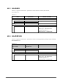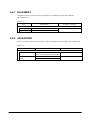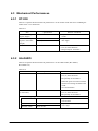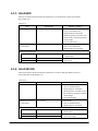
1
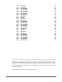
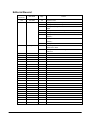
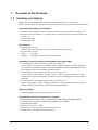
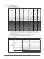
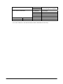
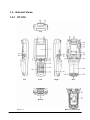
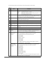
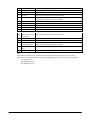
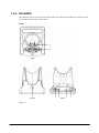
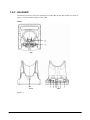
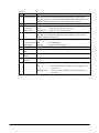
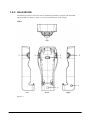
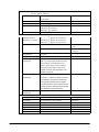
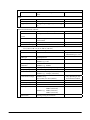
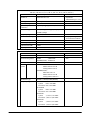
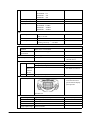
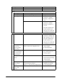
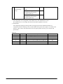
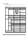
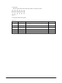
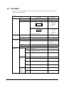
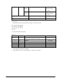
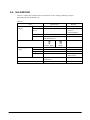
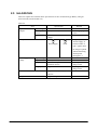
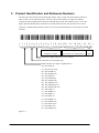
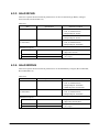
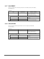
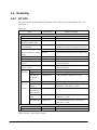
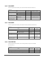
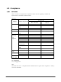
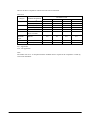
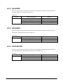
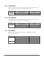
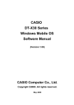
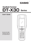
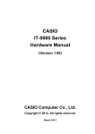
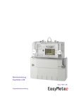
CASIO
DT-X30 Series
Hardware Manual
(Version 1.02)
CASIO Computer Co., Ltd.
Copyright ©2009. All rights reserved.
May 2009
Table of the Contents
Editorial Record
Chapter 1. Overview of the Products
1.1
Features at a Glance
1.2
Available Models
1.3
Options and Interfaces
1.4
External Views
1.4.1
DT-X30
1.4.2
HA-G60IO
1.4.3
HA-G62IO
1.4.4
HA-G30CHG
1.4.5
HA-G35CHG
1.4.6
HA-G32DCHG
1.4.7
HA-G20BAT
1.4.8
AD-S42120B
Chapter 2. Hardware Specifications
2.1
DT-X30
2.2
HA-G60IO
2.3
HA-G62IO
2.4
HA-G30CHG
2.5
HA-G35CHG
2.5.1
Mount Holes and Screws
2.6
HA-G32DCHG
2.7
HA-G20BAT
2.8
AD-S42120B
Chapter 3. Product Identification and Reference Numbers
Chapter 4. Quality References
4.1
Environmental Performances
4.1.1
DT-X30
4.1.2
HA-G60IO
4.1.3
HA-G62IO
4.1.4
HA-G30CHG
4.1.5
HA-G35CHG
4.1.6
HA-G32DCHG
4.1.7
HA-G20BAT
4.1.8
AD-S42120B
4.2
Electrical Performances
4.2.1
DT-X30
4.2.2
HA-G60IO
4.2.3
HA-G62IO
4.2.4
HA-G30CHG
4.2.5
HA-G35CHG
4.2.6
HA-G32DCHG
4.2.7
HA-G20BAT
4.2.8
AD-S42120B
4.3
Mechanical Performances
4.3.1
DT-X30
2
4
5
5
7
9
10
10
13
15
17
19
21
23
23
24
24
31
33
35
36
37
38
39
40
41
42
42
42
42
43
43
44
44
45
45
46
46
46
47
47
48
48
49
49
50
50
4.3.2
4.3.3
4.3.4
4.3.5
4.3.6
4.3.7
4.3.8
4.4
4.4.1
4.4.2
4.4.3
4.4.4
4.4.5
4.4.6
4.4.7
4.4.8
4.5
4.5.1
4.5.2
4.5.3
4.5.4
4.5.5
4.5.6
4.5.7
4.5.8
HA-G60IO
HA-G62IO
HA-G30CHG
HA-G35CHG
HA-G32DCHG
HA-G20BAT
AD-S42120B
Reliability
DT-X30
HA-G60IO
HA-G62IO
HA-G30CHG
HA-G35CHG
HA-G32DCHG
HA-G20BAT
AD-S42120B
Compliance
DT-X30
HA-G60IO
HA-G62IO
HA-G30CHG
HA-G35CHG
HA-G32DCHG
HA-G20BAT
AD-S42120B
50
51
51
52
52
53
53
54
54
55
55
55
56
56
56
56
57
57
59
59
59
60
60
60
61
No part of this document may be produced or transmitted in any form or by any means, electronic or
mechanical, for any purpose, without the express written permission of CASIO Computer Co., Ltd.
in Tokyo Japan. Information in this document is subject to change without advance notice. CASIO
Computer Co., Ltd. makes no representations or warranties with respect to the contents or use of this
manual and specifically disclaims any express or implied warranties of merchantability or fitness for
any particular purpose.
© 2009 CASIO Computer Co., Ltd. All rights reserved.
3
Editorial Record
Manual
Version no.
1.00
1.01
Date edited
Page
Content
June 2008
December 2008
All
31
33
35
Original version
In Chapter 2.2, Table 2.3 is updated.
In Chapter 2.3, Table 2.5 is updated.
In Chapter 2.5, Chapter 2.5.1 “Mount Holes and Screws” is
added.
In Chapter 4.4.3, Table 4.27 is updated.
In Chapter 1.1, EGPRS is corrected to “EGPRS (EDGE)”.
In Chapter 1.2, EGPRS in Table 1.1 is corrected to “EGPRS
(EDGE)”.
In Chapter 2.1, EGPRS in Table 2.1 is corrected to “EGPRS
(EDGE)”.
In Chapter 2.1, note about "Dead Pixels" is added.
The description about the new models with Windows
Mobile OS is added.
In Chapter 4.4.1, values for the digital camera are added in
Table 4.25.
55
5
7
26
1.02
May 2009
28
all
54
4
1. Overview of the Products
1.1 Features at a Glance
The DT-X30 series handheld terminal has been designed using the new concept of the
Human-centered Design Process and is capable of performing various powerful functions including;
Outstanding development environment
• Windows® CE 6.0 English Version as the integrated OS (model dependant. See Chapter 1.2.)
• Microsoft® Windows Mobile® 6.1 English Version as the integrated OS (model dependant. See
Chapter 1.2.)
• Visual Studio 2005
• Visual Studio 2008
CPU, Memory
• High-performance CPU
Marvell® PXA320 Application Processor (runs at 624 MHz, maximum)
• Large-capacity memory
RAM
: 128 MB
F-ROM
: 128 MB (User area; approximately 60 MB)
Capability of scanning industrial standard bar code symbologies
• 1D symbologies (with Laser Scanner models. See Chapter 1.2.)
UPC-A, UPC-E, EAN8, EAN13, Codabar, Code39, Code93, Code128, ITF, MSI, Industrial
2of5, IATA, GS1 DataBar Omnidirectional, GS1 DataBar Limited, GS1 DataBar Expanded,
GS1 DataBar Stacked, GS1 DataBar Expanded Stacked
• 1D symbologies (with C-MOS Imager models. See Chapter 1.2.)
UPC-A, UPC-E, EAN8, EAN13, Codabar, Code11, Code39, Code93, Code128, ITF, MSI,
Industrial 2of5, IATA, GS1 DataBar Omnidirectional, GS1 DataBar Limited, GS1 DataBar
Expanded
• 2D symbologies (with C-MOS Imager models. See Chapter 1.2.)
PDF417, Micro PDF, Code49, Composite, Codablock F, TLC39, GS1 DataBar Stacked, GS1
DataBar Omnidirectionalstacked, GS1 DataBar Expanded Stacked
Capturing images
• Integrated digital camera (2.0 Mega pixels, Auto focus)
Compatibility of various communication systems
• Integrated Wireless WAN module compatible with GSM, GPRS, and EGPRS (EDGE)
• Integrated WLAN module compatible with IEEE802.11b/g standard
• Integrated GPS module
• Bluetooth® Version 2.0 + EDR
• IrDA Version 1.3 for high speed infrared communication
• USB version 1.1 (Host/Client) for serial interface
5
High expandability
• microSD (SDHC) card slot
Improved environment durability
• Impact resistance
: 1.5 m in height*
• Dust/Water-splash proof : IP64 level (compliant with IEC60529 International Standard)
* ; The drop durability height is a measured value resulting from actual testing. It does not necessarily guarantee
the product from damage.
6
1.2 Available Models
Table 1.1 List of available models
Model no.
OS
(Note 1)
Scan
Engine
WLAN
(802.11 b/g)
WWAN
(GSM, GPRS,
EGPRS/EDGE),
GPS
No
Yes
Yes
No
No
Yes
Yes
Yes
Yes
No
Yes
Yes
No
Yes
Yes
Yes
Yes
Bluetooth
Camera
DT-X30R-10
CE
Laser
Yes
Yes
No
DT-X30G-10-CN
CE
Laser
No
Yes
No
DT-X30GR-10
CE
Laser
Yes
Yes
No
DT-X30R-30
CE
Imager
Yes
Yes
No
DT-X30R-30-CN
CE
Imager
Yes
Yes
No
DT-X30GR-30
CE
Imager
Yes
Yes
No
DT-X30GR-30-CN
CE
Imager
Yes
Yes
No
DT-X30GR-30C
CE
Imager
Yes
Yes
Yes
DT-X30GR-30C-CN
CE
Imager
Yes
Yes
Yes
DT-X30R-15
Mobile
Laser
Yes
Yes
No
DT-X30GR-15
Mobile
Laser
Yes
Yes
No
DT-X30GR-15C
Mobile
Laser
Yes
Yes
Yes
DT-X30R-35
Mobile
Imager
Yes
Yes
No
DT-X30GR-35
Mobile
Imager
Yes
Yes
No
DT-X30GR-35C
Mobile
Imager
Yes
Yes
Yes
DT-X30G-35U
Mobile
Imager
No
Yes
No
DT-X30G-35UC
Mobile
Imager
No
Yes
Yes
Notes:
1. “CE” denotes that the model integrates Windows CE 6.0 English Version for its operating
system, and “Mobile” denotes that the model integrates Windows Mobile 6.1 English Version
for its operating system.
2. “-CN” in the “Model no.” box denotes that the model is dedicated for China only.
3. The table shows all the models available current as of May 2009.
Table 1.2 List of options
Option
Product
Cradle
USB Cradle
Ethernet Cradle
Battery
Battery Pack
Battery charger
Dual Battery Charger
Cradle-type Battery Charger
Car Mounted-type Battery
Charger
Model no.
HA-G60IO
HA-G60IO-CN
HA-G62IO
HA-G62IO-CN
HA-G20BAT
HA-G20BAT-CN
HA-G32DCHG
HA-G32DCHG-CN
HA-G30CHG
HA-G30CHG-CN
HA-G35CHG
HA-G35CHG-CN
Continue.
7
Remark
AC adaptor
Power Cable for AD-S42120B
AD-S42120B
AD-S42120B-CN
AC-CORD-EU
AC-CORD-US
AC-CORD-TW
AC-CORD-KR
AC-CORD-AU
DT-380USB
HA-G90PS5
- For HA-G60IO, HA-G62IO,
HA-G30CHG, HA-G32DCHG
- For Europe
- For USA/Canada
- For Taiwan
- For Korea
- For Australia/New Zealand
- For between cradle and PC
Cable
USB cable
Others
Screen Protect Sheet
Note:
“-CN” in the “Model no.” box denotes that the model is dedicated for China only.
8
1.3 Options and Interfaces
Figure 1.1
9
1.4 External Views
1.4.1 DT-X30
Top
Left
Front
Right
Rear
Bottom
Figure 1.2
Battery Compartment
10
See the following table for the descriptions of each referenced part on the terminal.
Table 1.3
No.
Name
1
Speaker
2
Indicator 1
3
Indicator 2
4
Touch Screen
5
6
7
8
9
Microphone
Power Key
CLR Key
Center Trigger
Key
Execute Key
10
11
12
Cursor Keys
Numeric Keys
Fn Key
13
Function Keys
(Windows CE
models)
Function Keys
(Windows Mobile
models)
Description
Buzzer and voice messages are output.
Orange : Charging battery pack.
Green
: Charging battery pack is complete.
Red
: Battery pack is abnormal or the surrounding temperature is out
of the charging temperature range.
Flashes in blue when operating via Bluetooth or in orange when operating
via WLAN, WWAN or GPS. Lights in green when reading a bar code
successfully or in red when alarming (programmable).
Displays text and operating instructions. Also used to operate the terminal
and enter data using stylus provided.
Used to input a sound including voice sound. See note.
Turns on and off the power.
Used to clear one letter to the left of the input key.
Used to perform bar code reading. Can be assigned an arbitrary function.
Press when finishing entering numerical values or when moving to the
next step.
These keys operate much like PC’s cursor keys.
Used to enter numeric, decimal points, and letters.
Used to make various settings in combination with the function keys or
numeric keys or when starting a pre-registered application.
Various functions other than bar code reading can be assigned to these
keys. The assignments by default on the keys are as follows.
F1: Deletes the character on the left side of the cursor.
F2: Not assigned
F3: Not assigned
F4: Inputs “-“ (minus).
F5: Inputs a space.
F6: Not assigned.
F7: Not assigned.
F8: Changes text input mode. The input mode navigates to Numeric →
Uppercase letter → Lowercase letter.
Various functions other than bar code reading can be assigned to these
keys. The assignments by default on the keys are as follows.
F1: Left soft key.
F2: Right soft key.
F3: Not assigned
F4: Not assigned
F5: Not assigned
F6: Raises sound volume.
F7: Lowers sound volume.
F8: Not assigned.
Fn+F8: Changes text input mode. The input mode navigates to Numeric
→ Uppercase letter → Lowercase letter.
11
14
15
16
17
18
Strap Holes
L Trigger Key
R Trigger Key
IR Port
Reader Port
19
20
21
22
23
Stylus Holder
Reset Switch
Digital Camera
LED Light
Extension Port
24
Battery Pack Cover
Lock Switch
Battery Pack Cover
Strap Holes
Power Supply,
Charge Terminals
micro SD Card
Slot
SIM Card Slot
25
26
27
28
Used to attach the hand strap. Also used for the hand belt.
Used to perform bar code reading.
Used to perform bar code reading.
Used for communication with another terminal.
Laser light (Laser scanner models) or LED light (C-MOS Imager models)
is emitted from this port that reads bar codes.
Used to insert stylus.
Used to reset the terminal.
Used to capture photographs, images.
Used to light up an object when capturing it with the digital camera.
Provided for connecting an external device.
Used to lock the battery cover and to release it.
Used to cover the battery compartment that holds the battery pack inside.
Used to attach the strap.
Used to supply power to the terminal and to charge the battery pack via
either Cradle or Cradle-type Battery Charger.
For insertion of a micro SD card into the slot in the battery compartment.
29
For insertion of a micro SIM card into the slot in the battery compartment.
Note:
The following models do not integrate the microphone because the capability of voice data
transmission over Internet Protocol (VoIP) is prohibited by the Chinese radio related regulations.
DT-X30R-30-CN
DT-X30GR-30-CN
DT-X30GR-30C-CN
12
1.4.2 HA-G60IO
The following external views show the USB Cradles (HA-G60IO, HA-G60IO-CN). Refer to Table
1.4 for each referenced part on the cradle.
Views
Top
Rear
Front
Figure 1.3
13
Table 1.4
No.
Name
1
USB Client Port
2
3
USB Host Port
Selector Switch
4
5
AC Adaptor Jack
Terminal Detect
Switch
Power Contacts
Power LED
6
7
Description
This port is used to transmit data (download or upload) by connecting the
Cradle to a PC using USB cable (DT-380USB). The dedicated driver must
be installed in the PC before connecting the Cradle to the PC.
This port is used to connect a USB peripheral device.
This switch is used to switch between the USB host port and USB client
port.
Connect the dedicated AC adaptor, AD-S42120B, here.
This switch detects when the terminal is seated correctly on the Cradle.
Power is supplied to the terminal via these contacts.
This LED indicates the power status and the mounting status of the
terminal.
Off
: The terminal is not installed.
Flashing Green : Power is on and the terminal is mounted correctly.
14
1.4.3 HA-G62IO
The following external views show the Ethernet Cradles (HA-G62IO, HA-G62IO-CN). Refer to
Table 1.5 for each referenced part on the cradle.
Views
Top
Rear
Front
Figure 1.4
15
Table 1.5
No.
Name
1
USB Client Port
2
3
4
5
6
7
8
9
10
USB Host Port
LAN
Connection
Status LED
LAN Port
LAN
Communication
Status LED
Selector Switch
AC Adaptor
Jack
Terminal Detect
Switch
Ethernet Cradle
Contacts
Power LED
Description
This port is used to transmit data (download, upload) by connecting the
Ethernet Cradle to PC using USB cable (DT-380USB). The dedicated driver
must be installed in the PC before connecting the cradle to the PC.
This port is used to connect a USB peripheral device.
This LED shows the LAN connection status.
Off
: LAN cable not connected correctly.
On in Green
: LAN cable connected correctly.
This port is used for connecting the cradle to PC or hub via LAN cable so
that data can be transmitted (uploaded or downloaded). The special driver
must be installed in the terminal.
This LED shows the LAN operation status.
Off
: No communication.
Flashing
: Communication in progress.
This switch is used to switch between USB connection and LAN connection.
Connect the dedicated AC adaptor, AD-S42120B, here.
This switch detects when the terminal is mounted correctly on the cradle.
Power is supplied to the terminal via these contacts.
This LED indicates the power status and the mounting status of the terminal.
Off
: The terminal is not mounted. Or, the AC adaptor is not
connected.
Flashing Green
: Power is turned on, and the terminal is correctly set in
the cradle.
16
1.4.4 HA-G30CHG
The following external views show the Cradle-type Battery Chargers (HA-G30CHG,
HA-G30CHG-CN). Refer to Table 1.6 for each referenced part on the charger.
Views
Top
Front
Rear
Figure 1.5
17
Table 1.6
No.
Name
1 AC Adaptor
Jack
2 Terminal Detect
Switch
3 Power Contacts
4 Power LED
Description
Connect the dedicated AC adaptor, AD-S42120B, here.
This switch detects when the terminal is mounted correctly on the charger.
Power is supplied to the terminal via these contacts.
This LED indicates the power status and the mounting status of the terminal.
Off
: The terminal is not mounted.
Flashing Green : Power is turned on and the terminal is mounted correctly.
18
1.4.5 HA-G35CHG
The following external views show the Car Mounted-type Battery Chargers (HA-G35CHG,
HA-G35CHG-CN). Refer to Table 1.7 for each referenced part on the charger.
Views
Top
Left
Front
Figure 1.6
19
Right
Table 1.7
No.
Name
1
DC Jack
2
Remove Buttons
3
Terminal Detect
Switch
Power Contacts
Charge Indicator
LED
4
5
Description
This is used to supply power by connecting to cigarette lighter socket
in vehicle via the dedicated cable.
These are used to remove the terminal from the Car Mounted-type
Battery Charger.
This switch detects when the terminal is mounted correctly on the
charger.
Power is supplied to the terminal via these contacts.
This LED indicates the power status and the mounting status of the
terminal.
Off
: The terminal is not mounted.
Flashing Green
: Power is turned on and the terminal is mounted
correctly.
20
1.4.6 HA-G32DCHG
The following external views show the Dual Battery Chargers (HA-G32DCHG,
HA-G32DCHG-CN). Refer to Table 1.8 for each referenced part on the charger.
Views
Top
Bottom
Figure 1.7
21
Table 1.8
No.
Name
1
Charge Indicator
LED
2
3
Power Contacts
AC Adaptor Jack
4
Dual Battery
Charger Connection
Port
Connection Bracket
Attachment Holes
5
Description
This LED indicates the charge status of battery pack(s).
Off
: Battery pack is not mounted.
Red
: Charging.
Flashing Red
: Problem on battery pack.
Green
: Charging complete.
Flashing Green
: Standby.
Power is supplied to the battery packs via these contacts.
This is used to supply power by connecting the dedicated AC adaptor,
AD-S42120B, here.
Used to connect multiple Dual Battery Chargers each other.
The connection bracket attaches here when you connect multiple Dual
Battery Chargers.
22
1.4.7 HA-G20BAT
The following external view shows the Battery Packs (HA-G20BAT, HA-G20BAT-CN).
Figure 1.8
1.4.8 AD-S42120B
The following external view shows the AC Adaptor (AD-S42120B, AD-S42120B-CN).
The power cable does not come as standard with the AC adaptor, AD-S42120B. The above figure shows
the AD-S42120BE.
Figure 1.9
23
2. Hardware Specifications
2.1 DT-X30
Tables 2.1 and 2.2 explain about the hardware specifications of all models of DT-X30 series
including the models with “-CN” denotation.
Table 2.1
Item
CPU / Memory
CPU
Specification
Remark
Marvell® Xscale Processor PXA320 runs at
624 MHz
RAM
128 MB
FROM
128 MB (user area; approx. 60 MB)
Model dependant. See
OS
Microsoft® Windows® CE6.0 R2 English
Table 1.1.
Version
®
®
Microsoft Windows Mobile 6.1 English
Version
Laser Scanner (DT-X30R-10, G-10-CN, GR-10, GR-10C, R-15, GR-15, GR-15C)
Wave Length
650±10 nm
Optical Output
<1 mW
No. of scannings
100±20 per second
Resolution
0.127 mm (minimum) or greater
PCS
0.45 (minimum) or greater
Readable distance
Approximately 40 to 400 mm
Readable width
Max. 308 mm
- at 400 mm depth
Daylight for scanning
50,000 Lux or less
Readable bar code
UPC-A, UPC-E, EAN8 (JAN8), EAN13
symbologies
(JAN13), Codabar (NW-7), Code39,
Interleaved 2of5 (ITF), MSI, Industrial
2of5, Code93, Code128 (EAN128), IATA,
RSS-14 (GS1 DataBar Omnidirectional),
RSS Limited (GS1 DataBar Limited), RSS
Expanded (GS1 DataBar Expanded),
RSS-14 Stacked (GS1 DataBar Stacked),
RSS Expanded Stacked (GS1 DataBar
Expanded Stacked)
Continue.
24
CMOS Imager (DT-X30R-30, R-30-CN, GR-30, GR-30-CN, GR-30C, GR-30C-CN, R-35, G-35U,
G-35UC, GR-35, GR-35C)
Method
C-MOS Imager, 752 x 480 (Wide VGA),
monochrome
Aimer method
Laser 650+10nm or -5nm <1 mW
Laser emit angle
Redirected downward at 37 degree
Resolution
1D
: 0.15mm
Stacked 2D : 0.169mm
Matrix 2D : 0.339mm
PCS
0.45 (minimum)
Readable distance
(Resolution = 1.0mm)
Readable width
1D
: Approx. 40 to 410 mm
Stacked 2D : Approx. 50 to 250 mm
Matrix 2D : Approx. 60 to 150 mm
Max. 29 mm
Max. 265 mm
Focal distance
Daylight for scanning
Readable 1D
symbologies
Readable Stacked 2D
symbologies
Readable Matrix 2D
symbologies
Display
Display device
No. of dots
Dot pitch
Gradation
Display font
Backlight
Viewing angle
Continue.
- At readable distance 40
mm
- At readable distance
365 mm
4.5 inches
50,000 Lux or less
UPC-A, UPC-E, EAN8, EAN13, Codabar
(NW-7), Code39, MSI, Interleaved 2of5
(ITF), Code93, Code128 (EAN128),
Code11, IATA, RSS-14 (GS1 DataBar
Omnidirectional), RSS Limited, (GS1
DataBar Limited), RSS Expanded, (GS1
DataBar Expanded)
PDF417, Micro PDF, Code49, TLC39,
Composite, Codablock F, RSS-14 Stacked
(GS1 DataBar Omnidirectionalstacked),
RSS Expanded Stacked (GS1 DataBar
Expanded Stacked), RSS-14 Stacked (GS1
DataBar Stacked), RSS Expanded Stacked
(GS1 DataBar Expanded Stacked)
Aztec, DataMatrix, Maxicode, QR Code
3.5-inch Advanced 2-way TFT LCD
240 (horizontal) x 320 (vertical)
0.153 (horizontal) x 0.153 (vertical) mm
65,536 colors
Scalable font
LED backlight
50 degree or more (Up, Down, Left, Right)
25
See note 2.
Indicator
LED
Input
Keyboard
Control keys
Trigger keys
1pc x LED in 2 colors, 1pc x LED in 3
colors
See Table 1.3.
Power key, Reset switch
R Trigger key, L Trigger key, Center Trigger
key
Infrared communication interface
Standard
IrDA ver. 1.3 Low power compatible
Communication
Half duplex
process
Synchronization
Start and stop synchronous communication,
frame method
Baud rate (in bps)
9,600, 19,200, 38,400, 57,600, 115,200, 4M
Communication range 0 (contact) to 0.2 m
WLAN (DT-X30R-10, GR-10, GR-10C, R-30, R-30-CN, GR-30, GR-30-CN, GR-30C, GR-30C-CN,
R-15, GR-15, GR-15C, R-35, GR-35, GR-35C)
Standard
IEEE 802.11b/g
Module no.
LBWA18HEPZ-135
- By Murata
Manufacturing Co., Ltd.
Radio type
Spread Spectrum
Emission Designation
IEEE801.11b : D1D, G1D
- ITU
IEEE802.11g : G1D
Spectrum Spread
IEEE802.11 b : DSSS
modulation
IEEE802.11 g : OFDM
Modulation type
BPSK, QPSK, CCK, 16QAM, 64QAM
Frequency range
IEEE802.11b/g 2,400 to 2,483.5 MHz
Baud rate
IEEE802.11b : 11 Mbps (maximum)
IEEE802.11g : 54 Mbps (maximum)
Communication range IEEE802.11b/g :
- Vary depending on the
50 m (indoor) to 150 m (outdoor)
environment condition
Number of channels
13
Channel spacing
5MHz
Channel band width
22MHz
Output power
IEEE802.11b : 12dBm (minimum)
15dBm (maximum)
IEEE802.11g : 12dBm (minimum)
14dBm (maximum)
Other feature
Roaming among Access-Points
Continue.
26
Bluetooth Class 2 (DT-X30R-10, G-10-CN, GR-10, GR-10C, R-30, R-30-CN, GR-30, GR-30-CN,
GR-30C, GR-30C-CN, R-15, GR-15, GR-15C, R-35, GR-35, GR-35C)
Standard
Bluetooth® specification Ver.2.0+EDR
Module no.
LBMA46LCS3-140
- By Murata
Manufacturing Co., Ltd.
Radio type
Spread Spectrum
Emission Designation
F1D, G1D
- ITU
Spectrum Spread
Frequency Hopping (“FHSS”)
modulation
Modulation type
GFSK (1Mbps), Π/4-dqpsk (2Mbps),
8-DPSK (3Mbps)
Frequency range
2,400 to 2,483.5 MHz
Communication range Approx. 3 m
- Vary depending on the
environment conditions
Number of channels
79
Channel spacing
1 MHz
Channel band width
1 MHz
Output power
Max. 4 dBm (PowerClass 2)
GSM
Standard
Module no.
Emission Designation
Communication features
Data
Packet
transfer
Modulation type
Frequency range
GSM release 99
XT 75 REL1
GPRS
: 300KGXW
EGPRS(EDGE) : 300KG7W
Packet data
GPRS: Multi Slot Class 12
Mobile Station Class B
Coding Scheme CS1-4
EGPRS(EDGE):
Multi Slot Class 10
Mobile Station Class B
Coding Scheme MCS1-9
GSMK / 8-PSK (EGPRS(EDGE))
GSM850
Uplink : 824 to 849 MHz
Downlink : 869 to 894 MHz
E-GSM900
Uplink : 880 to 915 MHz
Downlink : 925 to 960 MHz
GSM1800
Uplink : 1,710 to 1,785 MHz
Downlink : 1,805 to 1,880 MHz
GSM1900
Uplink : 1,850 to 1,910 MHz
Downlink : 1,930 to 1,990 MHz
Continue.
27
- By Siemens AG
- ITU
No. of Channels
Channel spacing
Channel band width
Output power
GPS
General specification
Protocol
Sensitivity
SIM
Standard
General
specification
micro SD
Expansion port
USB
Host
Baud rate
Power to
external
device
Client
Baud rate
Power contacts
Terminal layout
GSM850 : 124
E-GSM900 : 174
GSM1800 : 374
GSM1900 : 299
200 KHz
200 KHz
GSM850 : 33 dBm
E-GSM900 : 33 dBm
GSM1800 : 30 dBm
GSM1900 : 30 dBm
16 channels and receiver / L1 1575.42
MHz, C /A code
NMEA-0183
Acquisition sensitivity: -141 dBm
Tracking sensitivity : -158 dBm
ISO7816 IC Card standard
3V, 1.8V SIM card supported
SDHC supported
- For connecting an
external device
Full speed (12 Mbps)
Low speed (1.5 Mbps)
- See Tables 2.3 and 2.5.
Full speed (12 Mbps)
- The layout is viewed
when the terminal is
placed with the display
panel upward.
See Table 2.2.
Camera
Number of pixels
Device
Aperture
Focal distance
Image capture range
Continue.
Approximately 2,000,000 pixels
1 / 4.0-type CMOS color
2.9
f = 3.45 mm (Auto focus)
10 cm to infinite
28
- 1,600 x 1,200 pixels
LED light
Speaker
Microphone
Power
Operating power
Memory backup
Operating period
21,000 mcd
Monaural
Monaural
- See note 1.
Lithium-ion battery pack
Lithium battery (rechargeable)
Approx. 8 hours
Approx. 13 hours
Approx. 12 hours
Memory backup
period (with
Memory backup
battery only)
Memory backup
period (with battery
pack and memory
backup battery)
Battery pack charge
period
Approx. 10 minutes for RAM
Approx. 96 hours for integrated clock
Memory backup
battery charge
period
Memory backup
battery rated
capacity
Approx. 30 minutes (for a level where
memory backup is possible.)
Approx. 1.5 days (for fully charged level)
25 mAh
- HA-G20BAT
- Integrated
- Based on the ratio of cyclic
operation of “Standby:
Scanning”: “WWAN” at
3:1:2.
- Based on the ratio of cyclic
operation of “Standby:
Scanning”: “WLAN” at
6.5:1.5:2.
- Under the conditions that
the CPU speed is set to
auto power save mode and
the backlight is turned off.
- Based on the ratio of cyclic
operation of “Standby: Key
input: Scanning” at 20:1:1.
- Under the condition that
the CPU speed is set to
auto power save mode and
the backlight is turned off.
- Lithium battery (on-board)
is fully charged.
- At room temperature.
Approx. 72 hours for RAM
- The backup period starts
when “Main battery low
warning” appears.
Approx. 5 hours
- Power on the terminal is
turned off while the battery
is being charged.
- At room temperature.
- Battery pack is being
installed in the terminal.
- At room temperature.
Continue.
29
Method to charge
memory backup
battery
When power supply is made via
cradle
When power supply is made by
installed battery pack (when
terminal’s power on )
When power supply is made by
installed battery pack (when
terminal’s power off)
Yes
Yes
Yes
Notes:
1. The microphone is not integrated in DT-X30R-30-CN, DT-X30GR-30-CN and
DT-X30GR-30C-CN to comply with the relevant radio regulations of China.
2. Dead Pixels
The LCD panel employed in this product uses high precision and substantial number of
components which commonly cause a small number of the pixels not to light or to remain lit all
the time. This is due to the characteristics of LCD panel yield in accuracy over 99.99% and
permissible.
Table 2.2
Pin no.
1
2
3
4
5
6
Signal
V CRADLE
D+
DUSB_ID
V BUS
GND
Description
Power supply/Charge to the terminal
USB D+
USB DSwitch-over between USB host and USB client
Power from USB cradle
GND
30
Direction
IN / OUT
IN / OUT
IN
OUT IN / OUT
-
2.2 HA-G60IO
Tables 2.3 and 2.4 and Figure 2.1 explain about the hardware specifications of the USB Cradles
(HA-G60IO, HA-G60IO-CN).
Table 2.3
USB
Item
Standard
Baud rate
Connector
Specification
USB Ver.1.1 compatible
Max. 12 Mbps (maximum)
1
2
4
3
Remark
-
1
2
3
4
VBus
– Data (D -)
+ Data (D+)
GND
-
1
2
3
4
VBus
– Data (D -)
+ Data (D+)
GND
USB connector B type
1
Power from
AC Adaptor
Input voltage
Current consumption
Plug
AC Adaptor
Power
USB host
USB
client
Charge/
Power
supply to
terminal
Dimensions
Weight
Standard
Baud rate
Power to
external
device
Standard
Baud rate
Pin Layout
Description
Output
voltage
Output
current
Charge
method
Battery
charge time
2
3
4
USB connector A type
DC 12V±5%
approx. 3A (max)
EIAJ RC-5320A type 4
AD-S42120B or
AD-S42120B-CN
USB Ver. 1.1
12 Mbps (maximum)
1.5 Mbps (minimum)
5V±5%, 500 mA (maximum)
- When supplying power
or transmitting data.
- Center +
- Dedicated AC adaptors
USB Ver. 1.1
12 Mbps (maximum)
See Figure 2.1.
See Table 2.4.
DC9.5±0.5V
2.7 A (maximum)
Constant voltage method
Approx. 5 hours
Approx. 120 (W) x 144 (D) x
129 (H) mm
Approx. 300 g
31
- With current limitation
control
• Pin layout
The pin layout below shows when the cradle is viewed at its front.
Figure 2.1
• Pin layout and the description
Table 2.4
Pin no.
1
2
3
4
5
6
Signal
V CRADLE
D+
DUSB_ID
V BUS
GND
Description
Power supply to the terminal and charge the battery
pack installed in the terminal.
USB D +
USB D Switch-over between USB host and USB client
Power from USB cradle
GND
32
Direction
IN / OUT
IN / OUT
OUT
IN / OUT
-
2.3 HA-G62IO
Tables 2.5 and 2.6 and Figure 2.2 explain about the hardware specifications of the Ethernet Cradles
(HA-G62IO, HA-G62IO-CN).
Table 2.5
USB
Item
Standard
Baud rate
Connector
Specification
USB Ver.1.1 compatible
Max. 12 Mbps (maximum)
1
2
4
3
Remark
-
1
2
3
4
VBus
– Data (D -)
+ Data (D+)
GND
-
1
2
3
4
VBus
– Data (D -)
+ Data (D+)
GND
USB connector B type
1
LAN
Power from
AC Adaptor
Power
Communication
protocol
Media type
Input voltage
Current consumption
Plug
AC Adaptor
USB host Standard
Baud
rate
Power to
external
device
USB
Standard
client
Baud
rate
Pin
layout
Descript
ion
Output
Charge/
voltage
Power
supply to Output
terminal
current
2
3
4
USB connector A type
IEEE802.3 standard
10base-T/100base-TX auto-switched
DC 12V±5%
approx. 3A (maximum)
EIAJ RC-5320A type 4
AD-S42120B or AD-S42120B-CN
USB Ver. 1.1
12 Mbps (maximum)
1.5 Mbps (minimum)
5V±5%, 500 mA (maximum)
USB Ver. 1.1
12 Mbps (maximum)
See Figure 2.2.
See Table 2.6.
DC9.5V±0.5V
2.7A (maximum)
Continue.
33
- When supplying
power or
transmitting data.
- Center +
Charge
method
Constant voltage method
Battery
charge
time
Approx. 5 hours
Dimensions
- By integrated
battery charge
circuit
- By integrated
battery charge
circuit
Approx. 120 (W) x 144 (D) x 129 (H)
mm
Approx. 300 g
Weight
• Pin layout
The pin layout below shows when the cradle is viewed at its front.
Figure 2.2
• Pin layout and the description
Table 2.6
Pin no.
1
2
3
4
5
6
Signal
V CRADLE
D+
DUSB_ID
V BUS
GND
Description
Power supply to the terminal and charge to
battery pack installed in the terminal.
USB D +
USB D Switch-over between USB host and USB client
Power from/to USB cradle
GND
Notes:
1. The output is made from the cradle.
2. The direction “OUT” is for USB mode, or “IN” for LAN mode.
34
Direction
IN / OUT
IN / OUT
OUT (Note 1)
IN / OUT (Note 2)
-
2.4 HA-G30CHG
Table 2.7 explains about the hardware specifications of the Cradle-type Battery Chargers
(HA-G30CHG, HA-G30CHG-CN).
Table 2.7
Item
Input from AC
Adaptor
Input voltage
Consumption
current
Plug
AC Adaptor
Specification
DC 12V±5%
2.6 A (maximum)
Remark
- When supplying
power or
transmitting data.
- Center pin +
EIAJ RC-5320A type 3
AD-S42120B or
AD-S42120B-CN
Pin layout
Power supply/
Charge
Dimensions
Weight
Output voltage
Output current
Charge method
Charge period
Power supply
DC9.5V±0.5V
2.7 A (maximum)
Constant voltage
Approx. 5 hours
GND
Approx. 120 (W) x 144 (D) x
129 (H) mm
Approx. 300 g
35
- By integrated battery
charge circuit
2.5 HA-G35CHG
Table 2.8 explains about the hardware specifications of the Car Mounted-type Battery Chargers
(HA-G35CHG, HA-G35CHG-CN).
Table 2.8
Item
Input from AC
Adaptor
Input voltage
Consumption
current
Plug
Specification
DC12 to 24V±5%
2.6A (maximum)
Remark
- When supplying
power
Dedicated cable bundled with the
charger
Pin layout
Power Supply
Power supply/
Charge
Output voltage
Output current
Charge method
Charge period
Dimensions
Weight
GND
DC 9.5V±0.5V
2.7 A (maximum)
Constant voltage (with current
limitation control)
Approx. 5 hours
Approx. 287 (W) x 80 (D) x 75
(H) mm
Approx. 620 g
36
- The pin layout “Power Supply” at
left and “GND” at
right - appears when
the charger is placed
with the front being
faced upward.
- See Figure 1.6.
- By integrated battery
charge circuit
- By integrated battery
charge circuit
2.5.1 Mount Holes and Screws
Use M4 Flat-head tapping
screws.
Figure 2.3
37
2.6 HA-G32DCHG
Table 2.9 explains about the hardware specifications of the Dual Battery Chargers (HA-G32DCHG,
HA-G32DCHG-CN).
Table 2.9
Item
Input from AC
Adaptor
Input voltage
Consumption
current
Specification
DC 12V±5%
approx. 0.03 A
approx. 3.5 A
Power supply/
Charge
Plug
AC Adaptor
Charge method
EIAJ RC-5320A type 4
AD-S42120B or AD-S42120B-CN
Constant voltage
Charge period
Approx. 4 hours
Approx. 5.5 hours
Dimensions
Weight
Approx. 104 (W) x 100 (D) x 50
(H) mm
Approx. 168 g
38
Remark
- No battery pack is
mounted.
- Battery pack(s) is
being charged.
- Center pin +
- With current
limitation control.
- To charge single
battery.
- To charge two
batteries at the same
time.
2.7
HA-G20BAT
Table 2.10 explains about the hardware specifications of the battery packs (HA-G20BAT,
HA-G20BAT-CN).
Table 2.10
Item
Rated capacity
Rated output voltage
Weight
Dimensions
Specification
14.8 WH (2,000 mAh)
DC 7.4 V
Approx. 107 g
Approx. 39 (W) x 72 (D) x 21 (H) mm
39
Remark
2.8 AD-S42120B
Table 2.11 explains the hardware specifications of the AC Adaptors (AD-S42120B,
AD-S42120B-CN).
Table 2.11
Parameter
Original manufacturer’s model no.
Specification
SA145A-1240U-6
Type
Input
requirements
Switching regulator
100 to 240VAC
90 to 264VAC
50 or 60 Hz
47 to 63 Hz
1200mA (maximum)
Output
requirements
Protections
Hi-Pot Test
(Dielectric
strength)
Insulation
resistance
Dimensions
Weight
Rated input voltage
Input voltage tolerance
Nominal frequency
Frequency tolerance
Input current
No load power
consumption
(Off mode)
Inrush current
0.5W or less
Average efficiency
83.6% (minimum)
Leakage current
Rated output voltage
Rated output current
Rated output power
Minimum output current
Line regulation
0.25 mA or less
DC12V
DC3.5A
42W
0A
±2% or les
Load regulation
Ripple noise
Over load protection
current
Over voltage protection
±5% or less
100 mVp-p or less
4.2 to 6.2 A
80A or less
Clamp 190% output
voltage maximum
AC3.0 KV for 1 second, 5mA (leak current) or
less
DC500V for 1 minute, 100MΩ or more
Approx. 111 (D) x 50 (W) x 31 (H) mm
Approx. 275 g
40
Remark
- By Sino-American
Electronic Co., Ltd.
- At input 100VAC/50Hz
with full load
- At input 240VAC/50Hz
- At input 100VAC to
240VAC
- At cold start, maximum
load.
- At input 115VAC/60Hz
and 230VAC/50Hz with
25%, 50%, 75% and
100% load
- At input 240VAC/50Hz
- At full load and ±10%
input voltage
- At O/P=12VDC, full load
- At input 100VAC to
240VAC
3. Product Identification and Reference Numbers
On the back of the terminal and the dedicated options, there is a bar code and numbers printed on
label as shown in the following figure. This bar code is represented by 15 digits of Code128
symbology and by alphanumeric characters beneath the bar code. The numbers from 1 to 9 in the
figure represent identification and references of individual terminal. The numbers from 10 to 14
represent a manufacturing reference which is reserved by the manufacturer. See the figure for each
meaning.
1
2
3
4
5
6
7
8
Serial number of the
terminal in 5 digits
10
9
11
Production year (last digit only)
Model number (two digits in alphanumeric)
E4 : DT-X30R-10
E5 : DT-X30G-10-CN
E6 : DT-X30GR-10
9D : DT-X30GR-10C
E8 : DT-X30R-30
EA : DT-X30GR-30
EB : DT-X30GR-30C
EC : DT-X30R-30-CN
ED : DT-X30GR-30-CN
EE : DT-X30GR-30C-CN
EF : DT-X30R-15
F1 : DT-X30GR-15
F3 : DT-X30R-35
F4 : DT-X30G-35
F5 : DT-X30GR-35
F6 : DT-X30GR-35C
F7 : DT-X30G-35UC
F8 : DT-X30G-35U
99 : DT-X30GR-15C
41
13
14
Manufacturing references
(reserved by the manufacture)
Production month of the year (1 to 9, A, B, C)
Figure 3.1
12
15
Check
digit
4. Quality References
This chapter describes about references of the DT-X30 and its dedicated options concerned with
environmental performance, regulatory compliance, mechanical and electric durability, etc.
4.1 Environmental Performances
4.1.1 DT-X30
Table 4.1 explains about the environment performances on all models of DT-X30 series.
Table 4.1
Item
Specification
Temperature
Operation
-20 ºC to 50 ºC
Non-operation
-20 ºC to 70 ºC
Humidity
Operation
10 % to 80 %RH
Non-operation
5 % to 90 %RH
Storage
Temperature
-20 ºC to 60 ºC
Humidity
5 % to 90 %RH
Dust and water-splash proof
IP64 level
Remark / Condition
- 0 to 40 ºC for charging battery
- No condensation
- Compliant with IEC60529 standard
4.1.2 HA-G60IO
Table 4.2 explains about the environment performances on the USB Cradles (HA-G60IO,
HA-G60IO-CN).
Table 4.2
Item
Specification
Temperature
Operation
0 ºC to 40 ºC
Non-operation
-20 ºC to 70 ºC
Humidity
Operation
10 % to 80 %RH
Non-operation
5 % to 90 %RH
Storage in carton box
Temperature
-20 ºC to 60 ºC
Humidity
10 % to 90 %RH
Dust and water-splash proof
Not applicable
42
Remark / Condition
- No condensation
- No condensation
4.1.3 HA-G62IO
Table 4.3 explains about the environment performances on the Ethernet Cradles (HA-G62IO,
HA-G62IO-CN).
Table 4.3
Item
Specification
Temperature
Operation
0 ºC to 40 ºC
Non-operation
-20 ºC to 70 ºC
Humidity
Operation
10 % to 80 %RH
Non-operation
5 % to 90 %RH
Storage in carton box
Temperature
-20 ºC to 60 ºC
Humidity
10 % to 90 %RH
Dust and water-splash proof
Not applicable
Remark / Condition
- No condensation
- No condensation
4.1.4 HA-G30CHG
Table 4.4 explains about the environment performances on the Cradle-type Battery Chargers
(HA-G30CHG, HA-G30CHG-CN).
Table 4.4
Item
Specification
Temperature
Operation
0 ºC to 40 ºC
Non-operation
-20 ºC to 70 ºC
Humidity
Operation
10 % to 80 %RH
Non-operation
5 % to 90 %RH
Storage in carton box
Temperature
-20 ºC to 60 ºC
Humidity
10 % to 90 %RH
Dust and water-splash proof
Not applicable
43
Remark / Condition
- No condensation
- No condensation
4.1.5 HA-G35CHG
Table 4.5 explains about the environment performances on the Car Mounted-type Battery Chargers
(HA-G35CHG, HA-G35CHG-CN).
Table 4.5
Item
Specification
Temperature
Operation
-20 ºC to 50 ºC
Non-operation
-40 ºC to 85 ºC
Humidity
Operation
10 % to 80 %RH
Non-operation
5 % to 90 %RH
Storage in carton box
Temperature
-20 ºC to 60 ºC
Humidity
10 % to 90 %RH
Dust and water-splash proof
Not applicable
Remark / Condition
- No condensation
- No condensation
4.1.6 HA-G32DCHG
Table 4.6 explains about the environment performances on the Dual Battery Chargers
(HA-G32DCHG, HA-G32DCHG-CN).
Table 4.6
Item
Specification
Temperature
Operation
0 ºC to 40 ºC
Non-operation
-20 ºC to 60 ºC
Humidity
Operation
10 % to 80 %RH
Non-operation
5 % to 90 %RH
Storage in carton box
Temperature
-20 ºC to 60 ºC
Humidity
10 % to 90 %RH
Dust and water-splash proof
Not applicable
44
Remark / Condition
- No condensation
- No condensation
4.1.7 HA-G20BAT
Table 4.7 explains environment performances on the Battery Packs (HA-G20BAT,
HA-G20BAT-CN).
Table 4.7
Item
Remark /
Condition
Specification
Temperature
Operation
Storage
Compatible with the temperature range for the terminal
during discharge, or with that of the battery chargers
during charge. See Table 4.1 for discharge. Or, any
one of Tables 4.2 to 4.6 for charge.
Compatible with the temperature range for the
terminal. See Table 4.1.
Humidity
Operation
Compatible with the humidity range for the terminal
during discharge, or with that of the battery chargers
during charge. See Table 4.1 for discharge. Or, any
one of Tables 4.2 to 4.6 for charge.
Storage
Compatible with the humidity range for the terminal.
See Table 4.1.
Storage in carton box
Temperature -25 to 30 ºC
- The period of
storage is
recommended
within one year.
Humidity
90 %RH or less
Water-splash resistance
Not applicable.
4.1.8 AD-S42120B
Table 4.8 explains environmental performances on the AC Adaptors (AD-S42120B,
AD-S42120B-CN).
Table 4.8
Item
Specification
Remark / Condition
Temperature
Operation
Storage
0 to 40 ºC
-20 to 60 ºC
Operation
Storage
20 to 80 %RH
10 to 90 %RH
Humidity
45
- No condensation
4.2 Electrical Performances
4.2.1 DT-X30
Table 4.9 explains about electric performances on all models of DT-X30 series including the models
with “-CN” denotation.
Table 4.9
Item
Current consumption
Anti-static strength
Malfunction
Destruction
Specification
DC 1.8A : DT-X30R-10, R-30, R-15, R-35
DC 2.2A : DT-X30G-10, G-35UC
DC 2.3A : DT-X30GR-10, GR-30
DC 2.4A : DT-X30GR-30C, GR-10C, GR-15,
GR-15C, GR-35, GR-35C
±4 KV (In contact)
±8 KV (In air)
±12 KV
Remark / Condition
- 150 pF, 330ohm
4.2.2 HA-G60IO
Table 4.10 explains about electric performances on the USB Cradles (HA-G60IO, HA-G60IO-CN).
Table 4.10
Item
Input voltage
Anti-static strength
In contact
In air
Instant power interruption
Line noise strength
Malfunction
Specification
DC12V±5%
Remark / Condition
±4 KV
±8 KV
10 milliseconds or less
- 150 pF, 330 ohm
1,000 V
-
46
Pulse frequency : 5KHz
Burst cycle : 300 milliseconds
Number of pulses : 75
Burst interval : 15 milliseconds
4.2.3 HA-G62IO
Table 4.11 explains about electric performances on the Ethernet Cradles (HA-G62IO,
HA-G62IO-CN).
Table 4.11
Item
Input voltage
Anti-static strength
In contact
In air
Instant power interruption
Line noise strength
Malfunction
Specification
DC12 V±5%
Remark / Condition
±4 KV
±8 KV
10 milliseconds or less
- 150pF, 330 ohm
1,000V
-
Pulse frequency : 5KHz
Burst cycle : 300 milliseconds
Number of pulses : 75
Burst interval : 15 milliseconds
4.2.4 HA-G30CHG
Table 4.12 explains about electric performances on the Cradle-type Battery Chargers (HA-G30CHG,
HA-G30CHG-CN).
Table 4.12
Item
Input voltage
Anti-static strength
In contact
In air
Instant power interruption
Line noise strength
Malfunction
Specification
DC12V±5%
Remark / Condition
±4 KV
±8 KV
10 milliseconds or less
- 150 pF, 330 ohm
1,000 V
-
47
Pulse frequency : 5 KHz
Burst cycle : 300 milliseconds
Number of pulses : 75
Burst interval : 15 milliseconds
4.2.5 HA-G35CHG
Table 4.13 explains about electric performances on the Car Mounted-type Battery Chargers
(HA-G35CHG, HA-G35CHG-CN).
Table 4.13
Item
Input voltage
Anti-static strength
In contact
In air
Instant power interruption
Line noise strength
Malfunction
Specification
DC12 to 24V±5%
Remark / Condition
±4 KV
±8 KV
10 milliseconds or less
- 150 pF, 330 ohm
1,000 V
-
Pulse frequency : 5 KHz
Burst cycle : 300 milliseconds
Number of pulses : 75
Burst interval : 15 milliseconds
4.2.6 HA-G32DCHG
Table 4.14 explains about electric performances on the Dual Battery Chargers (HA-G32DCHG,
HA-G32DCHG-CN).
Table 4.14
Item
Input voltage
Anti-static strength
In contact
In air
Line noise strength
Malfunction
Specification
DC12V±5%
Remark / Condition
±6 KV
±8 KV
- 150 pF, 330 ohm
1,000 V
-
48
Pulse frequency : 5 KHz
Burst cycle : 300 milliseconds
Number of pulses : 75
Burst interval : 15 milliseconds
4.2.7 HA-G20BAT
The following table explains electrical performances on the Battery Packs (HA-G20BAT,
HA-G20BAT-CN).
Table 4.15
Item
Anti-static strength
Malfunction
Destruction
Specification
Remark / Condition
6 KV (contact) / 8KV (in air)
12 KV (contact, in air)
4.2.8 AD-S42120B
Table 4.16 explains electrical performance on the AC Adaptors (AD-S42120B, AD-S42120B-CN).
Table 4.16
Item
Withstanding noise
Surge
Anti-static strength
(ESD)
Specification
Line to line: ±1KV (Peak)
Line to earth (ground): ±2KV (Peak)
±4 KV (direct contact)
±8 KV (direct contact)
49
Remark / Condition
- IEC61000-4-5
- IEC61000-4-2
4.3 Mechanical Performances
4.3.1 DT-X30
Table 4.17 explains about mechanical performances on all models of DT-X30 series including the
models with “-CN” denotation.
Table 4.17
Item
Resistance to drop
impact (height)
Resistance to drop
impact in carton box
(height)
Resistance to vibration
Specification
150 cm
70 cm (in individual carton box)
70 cm (in master carton box)
3.0 G
Remark / Condition
- 5 cycles on each of 6 faces and 4
corners.
- 1 cycle on each of 6 faces, 1 corner and
three edges.
- 10 to 55 Hz
- In X, Y, and Z directions
- Reciprocally for 30 minutes
4.3.2 HA-G60IO
Table 4.18 explains about mechanical performances on the USB Cradles (HA-G60IO,
HA-G60IO-CN).
Table 4.18
Item
Resistance to vibration
Resistance to vibration
(in carton box)
Specification
1.5 G or less
-
1.5 G or less
Resistance to drop impact
In bare condition
70 cm
In individual carton
In master carton
-
Remark / Condition
10 to 55 Hz
In X, Y, and Z directions
Reciprocally for 30 minutes
While the power is turned on and the
terminal is not being mounted on the
cradle.
No communication
10 to 55 Hz
In X, Y, and Z directions
Reciprocally for 30 minutes
- 1 cycle on each of 6 faces onto
concrete floor
- 1 cycle on each of 6 faces, 1 corner
and 3 edges
70 cm or less
50 cm or less
50
4.3.3 HA-G62IO
Table 4.19 explains about mechanical performances on the Ethernet Cradles (HA-G62IO,
HA-G62IO-CN).
Table 4.19
Item
Resistance to vibration
Resistance to vibration
(in carton box)
Specification
1.5 G or less
-
-
1.5 G or less
Resistance to drop impact
In bare condition
70 cm
In individual carton
In master carton
Remark / Condition
10 to 55 Hz
In X, Y, and Z directions
Reciprocally for 30 minutes
While the power is turned on and
the terminal is not being mounted
on the cradle.
No communication
10 to 55 Hz
In X, Y, and Z directions
Reciprocally for 30 minutes
- 1 cycle on each of 6 faces onto
concrete floor
- 1 cycle on each of 6 faces, 1 corner
and 3 edges
70 cm or less
50 cm or less
4.3.4 HA-G30CHG
Table 4.20 explains about mechanical performances on the Cradle-type Battery Chargers
(HA-G30CHG, HA-G30CHG-CN).
Table 4.20
Item
Resistance to vibration
Resistance to vibration
(in carton box)
Resistance to impact
In bare condition
In individual carton
In master carton
Specification
1.5 G or less
-
-
1.5 G or less
70 cm
Remark / Condition
10 to 55 Hz
In X, Y, and Z directions
Reciprocally for 30 minutes
While the power is turned on and
the terminal is not being mounted
on the charger.
No communication
10 to 55 Hz
In X, Y, and Z directions
Reciprocally for 30 minutes
- 1 cycle on each of 6 faces onto
concrete floor
- 1 cycle on each of 6 faces, 1
corner and 3 edges
70 cm or less
50 cm or less
51
4.3.5 HA-G35CHG
Table 4.21 explains about mechanical performances on the Car Mounted-type Battery Chargers
(HA-G35CHG, HA-G35CHG-CN).
Table 4.21
Item
Resistance to vibration
Resistance to vibration
(in carton box)
Resistance to impact
In bare condition
In individual carton
In master carton
Specification
3.0 G or less
3.0 G or less
70 cm
-
Remark / Condition
5 to 200 Hz
In X, Y, and Z directions
Reciprocally for 2 hours
5 to 200 Hz
Reciprocally for 4 hours
10 to 55 Hz
In X, Y, and Z directions
Reciprocally for 30 minutes
- 1 cycle on each of 6 faces and four
edges onto concrete
- 1 cycle on each of 6 faces, 1 corner
and 3 edges
70 cm or less
50 cm or less
4.3.6 HA-G32DCHG
Table 4.22 explains about mechanical performances on the Dual Battery Chargers (HA-G32DCHG,
HA-G32DCHG-CN).
Table 4.22
Item
Resistance to vibration
Resistance to vibration
(in carton box)
Resistance to impact
In bare condition
In individual carton
In master carton
Specification
1.5 G or less
1.5 G or less
70 cm
-
Remark / Condition
10 to 55 Hz
In X, Y, and Z directions
Reciprocally for 30 minutes
While the power is turned off.
10 to 55 Hz
In X, Y, and Z directions
Reciprocally for 30 minutes
- 1 cycle on each of 6 faces and 4
edges onto concrete floor
- 1 cycle on each of 6 faces, 1 corner
and 3 edges
70 cm or less
60 cm or less
52
4.3.7 HA-G20BAT
Table 4.23 explains about mechanical performances on the Battery Packs (HA-G20BAT,
HA-G20BAT-CN).
Table 4.23
Item
Resistance to vibration
Specification
1.5 G or less
Impact durability (in height of fall)
In bare condition
100 cm or less
In individual carton box
In master carton box
70 cm or less
70 cm or less
Remark / Condition
- 10 to 55 Hz
- In X, Y, and Z directions
- Reciprocally for 30 minutes
- 1 cycle on each of 6 faces onto P-tile
surface.
- 1 on each of 6 faces, 1 corner and 3
edges onto concrete surface.
4.3.8 AD-S42120B
Table 4.24 explains mechanical performances on the AC Adaptors (AD-S42120B,
AD-S42120B-CN).
Table 4.24
Item
Resistance to vibration
Specification
0.5 G or less
Impact durability (in height of fall)
In bare condition
70 cm or less
In individual carton box
In master carton box
70 cm or less
70 cm or less
53
Remark / Condition
- 10 to 100 Hz
- In X, Y, and Z directions
- Reciprocally for 10 minutes
- 1 cycle on each of 6 faces onto P-tile
surface.
- 1 cycle on each of 6 faces, 1 corner
and 3 edges onto concrete surface.
4.4 Reliability
4.4.1 DT-X30
Table 4.25 explains about reliability on all models of DT-X30 series including models with “-CN”
denotation.
Table 4.25
Item
Service life
Backlight
LCD
Discharge/charge cycle
longevity of battery pack
Battery pack storage period
(recommended)
Discharge/charge cycle
longevity of memory backup
battery
Laser Scanner
C-MOS Imager
LED for the digital
camera
No. of uses for the
digital camera
Key input Reset switch
durability Trigger keys
Keys (except
the Trigger
keys)
Mounting Battery pack
/removin On Cradle-type
g
charger
durability Car
Mounted-type
battery charger
On Ethernet
cradle
On USB cradle
Specification
Remark / Condition
15,000 hours
50,000 hours
500 times
- Half-value period
- MTTF (see note)
- 50% or more of the initial capacity
One year or less
-
20,000 times
50 times
10,000 hours
70,000 hours
1,000 hours
18,000,000 times
1,000 times
1,000,000 times
500,000 times
4,000 times
15,000 times
100,000 times
15,000 times
15,000 times
MTBF
Electronic parts
35,902 hours
Digital camera
102,596 hours
Note:
MTTF stands for “Mean time to failure”.
54
At temperature in the range of -25 ºC to 30 ºC
At 80% of the battery’s capacity recovery rate
Memory backup for a period of 10 minutes
Memory backup until the cut-off voltage level
- Until the brightness reaches to 50% of the
original brightness.
- The life time is calculated based on when the
flash is illuminated.
- 500 (times/day) x 365 (day) x 5 (year)
- 250 (times/day) x 365 (day) x 5 (year)
- 2 (times/day) x 365 (day) x 5 (year)
- 2 (terminals/Cradle-type charger) x 4
(times/day) x 365 (day) x 5 (year)
- 50 (accesses/day) x 365 (day) x 5 (year)
- 2 (terminals/Ethernet cradle) x 4 (times/day) x
365 (day) x 5 (year)
- 2 (terminals/USB cradle) x 4 (times/day) x
365 (day) x 5 (year)
- Main PCB, Sub-PCB, Key PCB
-
4.4.2 HA-G60IO
Table 4.26 explains about reliability on the USB Cradles (HA-G60IO, HA-G60IO-CN).
Table 4.26
Item
MTBF for electronic parts
Installing and removing USB Client port connector
USB Host port connector
Mounting the terminal on the cradle and removing
Switching
Selector switch (USB Host
or USB Client)
Installing AC adaptor to AC adaptor jack
and removing from
Specification
100,000 hours
260 times
260 times
15,000 times
500 times
Remark / Condition
- One reciprocal switching
is counted as one time.
100 times
4.4.3 HA-G62IO
Table 4.27 explains about reliability on the Ethernet Cradles (HA-G62IO, HA-G62IO-CN).
Table 4.27
Item
Specification
MTBF for electronic parts
Installing and removing
USB port’s connector
LAN port’s connector
Mounting the terminal and removing
Switching
Selector switch (USB Host or USB
Client)
Installing AC adaptor to
and removing from
AC adaptor jack
50,000 hours
260 times
100 times
15,000 times
500 times
Remark /
Condition
- One reciprocal
switching as
one time
100 times
4.4.4 HA-G30CHG
Table 4.28 explains about reliability on the Cradle-type Battery Chargers (HA-G30CHG,
HA-G30CHG-CN).
Table 4.28
Item
Specification
MTBF for electronic parts
Mounting the terminal and removing from
Connecting to the joint connector and removing from
55
100,000 hours
15,000 times
100 times
Remark /
Condition
4.4.5 HA-G35CHG
Table 4.29 explains about reliability on the Car Mounted-type Battery Chargers (HA-G35CHG,
HA-G35CHG-CN).
Table 4.29
Item
Specification
MTBF for electronic parts
Mounting the terminal on and removing from
Installing cable to and removing from
DC jack
Remark /
Condition
100,000 hours
100,000 times
100 times
4.4.6 HA-G32DCHG
Table 4.30 explains about reliability on the Dual Battery Chargers (HA-G32DCHG,
HA-G32DCHG-CN).
Table 4.30
Item
Specification
MTBF for electronic parts
Mounting HA-G20BAT and removing it from
Connecting to the joint connector and removing from
Installing AC adaptor to and removing from AC adaptor jack
Remark /
Condition
50,000 hours
5,000 times
100 times
100 times
4.4.7 HA-G20BAT
Table 4.31 explains about reliability on the Battery Packs (HA-G20BAT, HA-G20BAT-CN).
Table 4.31
Item
Battery charge-discharge
cyclic life
Specification
500 cycles
Remark / Condition
- Environment temperature : ordinary
- The capacity after 500 cycles remains 50%
of its initial capacity or more.
4.4.8 AD-S42120B
Table 4.32 explains about reliability on the AC Adaptors (AD-S42120B, AD-S42120B-CN).
Table 4.32
Item
MTBF
Specification
100,000 hours
56
Remark / Condition
- At 25 ºC MIL-HDBK-217F
4.5 Compliance
4.5.1 DT-X30
Tables 4.33 and 4.34 explain about compliance with the relevant regulatory standards and
requirements for all models of DT-X30 series.
Table 4.33
Category
Safety
EMC
EMI
WLAN,
Bluetooth
Type
Approval
Bluetooth
Logo
Laser/LED
Standard / Requirement
EN60950-1
CNS14336 (Taiwan)
(note)
IEC60950-1 2nd edition
RRL (Korea) (note)
CNS13438 (Taiwan)
(note)
EN 300328
EN 301489-7 V1.2.1
EN 301489-17 V1.2.1
EN 301511 V9.0.2
EN50360
EN50371
LP0002 or RTTE02
(Taiwan) (note)
PLMN01 (Taiwan)
(note)
RRL (Korea) (note)
PRD 2.0
DT-X30xx-xxx
GR-10, GR-30, GR-30C. GR-35,
R-10, R-30, R-35
GR-35C
Yes
Yes
Yes
Yes
EN60825-1
IEC60825-1
IEC60529, Level IP64
Dust and
water-splash
Denotation
Yes ; Applicable
N/A ; Not applicable
Yes
Yes
Yes
Yes
N/A
Yes
Yes
N/A
Yes
N/A
N/A
Yes
Yes
Yes
Yes
Yes
Yes
Yes
Yes
Yes
N/A
Yes
Yes
Yes
N/A
Yes
Yes
Yes
Yes
Yes
Yes
Yes
Note:
The model with “Yes” is complaint with the standard when a request on the compliance is made by
Casio local distributor.
57
Table 4.34 shows compliance with the relevant Chinese standards.
Table 4.34
Category
Safety
EMI
SRRC
GSM
Standard / Requirement
nd
IEC60950-1 2 edition
GB4943 (CCC)
GB9254 (CCC)
GB17625.1 (CCC)
2002-353
YD/T 1214-2006 &
YD/T 1215-2006
PRD 2.0
Bluetooth
Logo
Laser/LED
IEC60825-1
Environment IEC60529, Level IP64
Denotation
Yes ; Applicable
N/A ; Not applicable
G-10-CN
Yes
Yes
Yes
Yes
Yes
Yes
DT-X30xx-xx-CN
R-30-CN
GR-30-CN
Yes
Yes
Yes
Yes
Yes
Yes
Yes
Yes
Yes
Yes
N/A
Yes
GR-30C-CN
Yes
Yes
Yes
Yes
Yes
Yes
Yes
Yes
Yes
Yes
Yes
Yes
Yes
Yes
Yes
Yes
Yes
Yes
Note:
The model with “Yes” is compliant with the standard when a request for the compliance is made by
Casio local distributor.
58
4.5.2 HA-G60IO
Table 4.35 explains about compliance with the relevant regulatory standards and requirements for
the USB Cradles (HA-G60IO, HA-G60IO-CN).
Table 4.35
Category
EMC
Standard / Requirement
CFR 47 Part 15 Subpart B
ICES003
EN55022, EN55024
EN61000-3-2, EN61000-3-3
Remark
-
USA
Canada
EU
EU
4.5.3 HA-G62IO
Table 4.36 explains about compliance with the relevant regulatory standards and requirements for
the Ethernet Cradles (HA-G62IO, HA-G62IO-CN).
Table 4.36
Category
EMC
Standard / Requirement
CFR 47 Part 15 Subpart B
EN55022, EN55024
EN61000-3-2, EN61000-3-3
Remark
- USA
- EU
- EU
4.5.4 HA-G30CHG
Table 4.37 explains about compliance with the relevant regulatory standards and requirements for
the Cradle-type Battery Chargers (HA-G30CHG, HA-G30CHG-CN).
Table 4.37
Category
EMC
Standard / Requirement
CFR 47 Part 15 Subpart B
EN55022, EN55024
EN61000-3-2, EN61000-3-3
59
Remark
- USA
- EU
- EU
4.5.5 HA-G35CHG
Table 4.38 explains about compliance with the relevant regulatory standards and requirements for
the Car Mounted-type Battery Chargers (HA-G35CHG, HA-G35CHG-CN).
Table 4.38
Category
EMC
Standard / Requirement
CFR 47 Part 15 Subpart B
EN55022, EN55024
Remark
- USA
- EU
4.5.6 HA-G32DCHG
Table 4.39 explains about compliance with the relevant regulatory standards and requirements for
the Dual Battery Chargers (HA-G32DCHG, HA-G32DCHG-CN).
Table 4.39
Category
EMC
Standard / Requirement
CFR 47 Part 15 Subpart B
EN55022, EN55024
EN61000-3-2, EN61000-3-3
Remark
- USA
- EU
- EU
4.5.7 HA-G20BAT
Table 4.40 explains about compliance with applicable requirements for the Battery Packs
(HA-G20BAT, HA-G20BAT-CN).
Table 4.40
Category
EMC
Safety
Standard / Requirement
EN55022
EN55024
EN61000-3-2
EN61000-3-3
UL2054
UL60950-1
60
Remark
-
EU
EU
EU
EU
USA
USA
4.5.8 AD-S42120B
Table 4.41 explains about compliance with the relevant regulatory standards and requirements for
the AC Adaptors (AD-S42120B, AD-S42120B-CN).
Table 4.41
Category
EMC
Safety
Standard / Requirement
UL60950 3rd edition
CAN/CSA C222 NO.60950-00 1st edition
EN60950-1:2001+A11
AS/NZS60950-1:2000
IEC60950-1:2001
K60950-1
CNS14336 (94)
GB4943-2001
CFR47 FCC Part 15 Subpart B
EN55022:2006
EN55024:1998+A1:2001+A2:2003
EN61000-3-2:2000+A2:2005
EN61000-3-3:1995+A1:2001+A2:2005
GB9254-1998
GB17625.1-2003
CNS13438 (95)
AZ/NZS CISPR22
61
-
Remark
USA
Canada
EU
Australia, New Zealand
CB certificate
Korea
Taiwan
China
USA, Canada
EU
EU
EU
EU
China
China
Taiwan
Australia, New Zealand