1
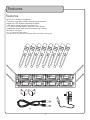
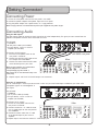
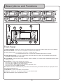
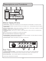
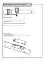
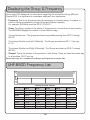
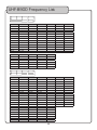
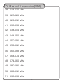
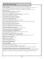
UHF-8900
UHF PLL WIRELESS MIC SYSTEM WITH FREQUENCY SCAN
o
w
n
e
r
'
s
m
a
n
u
a
l
Table of Contents
Safety Instructions . . . . . . . .
FCC Information . . . . . . . . . .
Welcome . . . . . . . . . . . . . .
Listening for a Lifetime . . . . .
Features . . . . . . . . . . . . . .
Getting Connected . . . . . . . .
Descriptions and Functions . .
Setting up the Microphones .
Re-syncing the Microphones .
Using the Wireless Mics . . . .
Basic Operations . . . . . . . . .
Advanced Operations . . . . . .
Frequency Reference . . . . . .
Troubleshooting . . . . . . . . . .
.
.
.
.
.
.
.
.
.
.
.
.
.
.
.
.
.
.
.
.
.
.
.
.
.
.
.
.
.
.
.
.
.
.
.
.
.
.
.
.
.
.
.
.
.
.
.
.
.
.
.
.
.
.
.
.
.
.
.
.
.
.
.
.
.
.
.
.
.
.
.
.
.
.
.
.
.
.
.
.
.
.
.
. 3
. 4
. 5
. 6
. 7
. 8
10
13
16
17
18
19
20
23
Safety Instructions
8. Ventilation - The appliance should be situated so its
location does not interfere with its proper ventilation.
For example, the appliance should not be situated on a
bed, sofa, rug, or similar surface that may block the
ventilation slots.
CAUTION
RISK OF SHOCK
CAUTION: To reduce the risk of electric
shock, do not remove cover (or back). No
user-serviceable parts inside. Only refer
servicing to qualified service personnel.
9. Heat - The appliance should be situated away from
heat sources such as radiators, heat registers,
stoves, or other appliances (including amplifiers)
that produce heat.
10. Power Sources - The appliance should be
connected to a power supply only of the type
described in the operating instructions or as marked
on the appliance.
Explanation of Graphical Symbols
The lightning flash & arrowhead
symbol, within an equilateral triangle,
is intended to alert you to the
presence of danger.
11. Grounding or Polarization - Precautions should be
taken so that the grounding or polarization means of
an appliance is not defeated.
12. Power-Cord Protection - Power-supply cords
should be routed so that they are not likely to be
walked on or pinched by items placed upon or
against them, paying particular attention to cords at
plugs, convenience receptacles, and the point where
they exit from the appliance.
The exclamation point within an
equilateral triangle is intended to alert
you to the presence of important
operating and servicing instructions.
WARNING
13. Cleaning - Unplug this unit from the wall outlet
before cleaning. Do not use liquid cleaners or
aerosol cleaners. Use a damp cloth for cleaning.
To reduce the risk of fire or electric shock, do
not expose this unit to rain or moisture.
14. Power lines - An outdoor antenna should be
located away from power lines.
1. Read Instructions - All the safety and operating
instructions should be read before the appliance is
operated.
15. Nonuse Periods - The power cord of the appliance
should be unplugged from the outlet when left unused
for a long period of time.
2. Retain Instructions - The safety and operating
instructions should be retained for future reference.
16. Object and Liquid Entry - Care should be taken so
that objects do not fall and liquids are not spilled into
the enclosure through openings.
3. Heed Warnings - All warnings on the appliance and in
the operating instructions should be adhered to.
17. Damage Requiring Service - The appliance should
be serviced by qualified service personnel when:
4. Follow Instructions - All operating and use
instructions should be followed.
A.
B.
C.
D.
The power supply cord or plug has been damaged; or
Objects have fallen into the appliance; or
The appliance has been exposed to rain; or
The appliance does not appear to operate normally
or exhibits a marked change in performance; or
E. The appliance has been dropped, or the enclosure
damaged.
5. Attachments - Do not use attachments not
recommended by the product manufacturer as they
may cause hazards.
6. Water and Moisture - Do not use this unit near water.
For example, near a bathtub or in a wet basement and
the like.
18. Servicing - The user should not attempt to service
the appliance beyond that described in the operating
instructions. All other servicing should be referred to
qualified service personnel.
7. Carts and Stands - The appliance should be used
only with a cart or stand that is recommended by the
manufacturer.
Note:
To CATV system installer's (U.S.A.): This reminder is
provided to call the CATV system installer's attention to
Article 820-40 of the NEC that provides guidelines for
proper grounding and, in particular, specifies that the
cable ground shall be connected as close to the point of
cable entry as practical.
7 A. An appliance and cart combination
should be moved with care. Quick stops,
excessive force, and uneven surfaces may
cause an overturn.
3
FCC Information
1. IMPORTANT NOTICE: DO NOT MODIFY THIS
UNIT!: This product, when installed as indicated in the
instructions contained in this manual, meets FCC
requirements. Modifications not expressly approved by
Vocopro may void your authority, granted by the FCC,
to use this product.
2. IMPORTANT: When connecting this product to
accessories and/or another product use only high
quality shielded cables. Cable(s) supplied with this
product MUST be used. Follow all installation
instructions. Failure to follow instructions could void your
FCC authorization to use this product in the U.S.A.
3. NOTE: This product has been tested and found to
comply with the requirements listed in FCC Regulations,
Part 15 for Class "B" digital devices. Compliance with
these requirements provides a reasonable level of
assurances that your use of this product in a residential
environment will not result in harmful interference with
other electronic devices. This equipment
generates/uses radio frequencies and, if not installed
and used according to the instructions found in the
owner's manual, may cause interference harmful to the
operation of other electronic devices. Compliance with
FCC regulations does not guarantee that interference
will not occur in all installations. If this product is found
to be the source of interference, which can be
determined by turning the unit "Off" and "On", please try
to eliminate the problem by using one of the following
measures:
Relocate either this product or the device that is being
affected by the interference.
Use power outlets that are on different branch (circuit
breaker or fuse) circuits or install AC line filter(s).
In the case of radio or TV interference, relocate/reorient
the antenna. If the antenna lead-in is 300-ohm ribbon
lead, change the lead-in to coaxial type cable.
If these corrective measures do not produce satisfactory
results, please contact your local retailer authorized to
distribute Vocopro products. If you can not locate the
appropriate retailer, please contact Vocopro, 1728
Curtiss Court, La Verne, CA 91750.
CAUTION
The apparatus is not disconnected from the AC power
source so long as it is connected to the wall outlet,
even if the apparatus itself is turned off. To fully ensure
that the apparatus is indeed fully void of residual power,
leave unit disconnected from the AC outlet for at least
fifteen seconds.
CAUTION:
READ THIS BEFORE OPERATING YOUR UNIT
1. To ensure the finest performance, please read this
manual carefully. Keep it in a safe place for future
reference.
2. Install your unit in a cool, dry, clean place - away from
windows, heat sources, and too much vibration, dust,
moisture or cold. Avoid sources of hum (transformers,
motors). To prevent fire or electrical shock, do not
expose to rain and water.
3. Do not operate the unit upside-down.
4. Never open the cabinet. If a foreign object drops into
the set, contact your dealer.
5. Place the unit in a location with adequate air
circulation. Do not interfere with its proper ventilation;
this will cause the internal temperature to rise and may
result in a failure.
6. Do not use force on switches, knobs or cords. When
moving the unit, first turn the unit off. Then gently
disconnect the power plug and the cords connecting to
other equipment. Never pull the cord itself.
7. Do not attempt to clean the unit with chemical solvents:
this might damage the finish. Use a clean, dry cloth.
8. Be sure to read the "Troubleshooting" section on
common operating errors before concluding that your
unit is faulty.
9. This unit consumes a fair amount of power even when
the power switch is turned off. We recommend that you
unplug the power cord from the wall outlet if the unit is
not going to be used for a long time. This will save
electricity and help prevent fire hazards. To disconnect
the cord, pull it out by grasping the plug. Never pull the
cord itself.
10. To prevent lightning damage, pull out the power cord
and remove the antenna cable during an electrical
storm.
11. The general digital signals may interfere with other
equipment such as tuners or receivers. Move the
system farther away from such equipment if
interference is observed.
NOTE:
Please check the copyright laws in your country
before recording from records, compact discs,
radio, etc. Recording of copyrighted material may
infringe copyright laws.
Voltage Selector (General Model Only)
Be sure to position the voltage selector to match the
voltage of your local power lines before installing the
unit.
110V
4
Welcome
And thank you for purchasing the UHF-8900 from VocoPro, your ultimate choice in
vocal entertainment! With years of experience in the music entertainment business,
VocoPro is a leading manufacturer of vocal equipment, and has been providing patrons
of bars, churches, schools, clubs and individual consumers the opportunity to sound like
a star with full-scale club models, in-home systems and mobile units. All our products
offer solid performance and sound reliability, and to reinforce our commitment to
customer satisfaction, we have customer service and technical support professionals
ready to assist you with your needs. We have provided some contact information for
you below.
VocoPro
1728 Curtiss Court
La Verne, CA 91750
Toll Free: 800-678-5348
TEL: 909-593-8893
FAX: 909-593-8890
VocoPro Company Email Directory
Customer Service & General Information
[email protected]
Tech Support
[email protected]
Remember Our Website
Be sure to visit the VocoPro website www.vocopro.com for the latest information on
new products, packages and promos. And while you're there don't forget to check out
our Club VocoPro for Karaoke news and events, chat rooms, club directories and even
a KJ Service directory!
We look forward to hearing you sound like a PRO, with VocoPro, the singer’s ultimate
choice.
FOR YOUR RECORDS
Please record the model number and serial number below, for easy reference, in case of loss or theft. These
numbers are located on the rear panel of the unit. Space is also provided for other relevant information
Model Number
Serial Number
Date of Purchase
Place of Purchase
5
Listening for a Lifetime
Selecting fine audio equipment such as the unit youʼve just purchased is only the start of your
musical enjoyment. Now itʼs time to consider how you can maximize the fun and excitement your
equipment offers. VocoPro and the Electronic Industries Associationʼs Consumer Electronics
Group want you to get the most out of your equipment by playing it at a safe level. One that lets
the sound come through loud and clear without annoying blaring or distortion and, most
importantly, without affecting your sensitive hearing.
Sound can be deceiving. Over time your hearing “comfort level” adapts to a higher volume of
sound. So what sounds “normal” can actually be loud and harmful to your hearing. Guard
against this by setting your equipment at a safe level BEFORE your hearing adapts.
To establish a safe level:
• Start your volume control at a low setting.
• Slowly increase the sound until you can hear it comfortably and clearly, and without
distortion.
Once you have established a comfortable sound level:
• Set the dial and leave it there.
• Pay attention to the different levels in various recordings.
Taking a minute to do this now will help to prevent hearing damage or loss in the future. After all,
we want you listening for a lifetime.
Used wisely, your new sound equipment will provide a lifetime of fun and enjoyment. Since
hearing damage from loud noise is often undetectable until it is too late, this manufacturer and
the Electronic Industries Associationʼs Consumer Electronics Group recommend you avoid
prolonged exposure to excessive noise. This list of sound levels is included for your protection.
Some common decibel ranges:
Level
30
40
50
60
70
80
Example
Quiet library, Soft whispers
Living room, Refrigerator, Bedroom away from traffic
Light traffic, Normal Conversation
Air Conditioner at 20 ft., Sewing machine
Vacuum cleaner, Hair dryer, Noisy Restaurant
Average city traffic, Garbage disposals, Alarm clock at 2 ft.
The following noises can be dangerous under constant exposure:
Level
90
100
120
140
180
Example
Subway, Motorcycle, Truck traffic, Lawn Mower
Garbage truck, Chainsaw, Pneumatics drill
Rock band concert in front of speakers
Gunshot blast, Jet plane
Rocket launching pad
-Information courtesy of the Deafness Research Foundation
6
Features
Features
•
•
•
•
•
•
8 UHF PLL wireless microphones
Frequency scan feature finds interference-free channels
More than 150 wireless frequencies available
LCD display shows frequency and other info
19” rack mountable chassis, uses just 2 rack spaces
Independent power knob and volume control per channel
• 8 balanced XLR outputs
• (2) ¼” unblanced mixed outputs
• Includes (2) ¼” unbalanced microphone cables and metal carrying case
(2)
7
Getting Connected
Connecting Power
1. Ensure the main power switch on the rear panel is set to OFF.
2. Connect the power adapter to the power input on the rear panel.
3. Plug the power adapter into a power outlet, or a surge protector.
Note: A surge protector is recommended to protect your equipment from power surges.
Connecting Audio
Using the XLR outputs
The XLR outputs allow you to connect each channel to the mixer independently. This gives you more control over the
individual microphone channels when connected to a mixer.
You will need:
• UHF-8900
• 8 XLR patch cables (not included)
• An input device, such as a mixer or
amplifier (not included)
To Connect the XLR outputs:
1. Ensure the main power switch on the
rear panel is turned off.
2. Connect one end of an XLR cable to the
CH.1 output of the UHF-8900.
3. Connect the other end of the XLR cable
to the desired input on your mixer.
4
3
2
1
UHF-8900 rear panel
4
3
2
1
Mixer
Note: To avoid confusion, it’s recommended
that the XLR jacks are attached
correspondingly (e.g. CH.1 to CH. 1,
CH. 2 to CH. 2, etc. The illustrated setup is for
clarity only.)
4. Repeat steps 2 and 3 until all the XLR outputs are connected.
Using the ¼” mixed output
The ¼” mixed output is useful if you do not have a mixer or if you have limited inputs available on your mixer. All 4
microphone signals are mixed together in
this output.
You will need:
• UHF-8900
• (2) ¼” patch cables (included)
• An input device, such as a mixer or
amplifier (not included)
UHF-8900 rear panel
To Connect the ¼” output:
1. Ensure the main power switch on the
rear panel is turned off.
2. Connect one end of a ¼” cable to one of
the ¼” mixed output on the rear panel of
the UHF-8900.
3. Connect the other end of the ¼” cable
to the desired input on your mixer or
amplifier.
4. Repeat steps 2 and 3 for the second ¼” mixed output jack.
8
Mixer
Getting Connected
Connecting Antennas
The Antennas receive the UHF wireless signals from the microphones.
1. Attach the antennas to the connectors on the front panel by twisting them clockwise until firmly attached.
2. To disconnect the antennas, twist counter-clockwise.
Note: Please be sure to attach the 900MHz antennas to the top 2 antenna posts and attach the 600MHz antennas
to the bottom 2 posts.
Attaching the Rack Brackets
The UHF-8900 comes with detachable rack brackets which allows the unit to be installed in a standard 19 inch rack.
1. Use the included screws to fasten the rack brackets to the sides of the UHF-8900 as shown in the illustration below.
Mounting the UHF-8900 in a Rack
The UHF-8900 will fit in a standard 19” rack (not included).
1. Align the UHF-8900 with the desired space in rack and slowly slide in, rear panel first.
Note: Depending on your rack case design, it may be necessary to allow for sufficient space for the antennas.
2. While aligned, use rack case screws (not included) in the order shown below to stabilize the UHF-8900 in its space,
using the “X” rotation (numbered below) will ensure even tension and flush alignment.
Note: Do not tighten screws firmly until all screws are in place.
1
2
3
4
9
Descriptions and Functions
1
3
2
4
8
5
7
6
Front Panel
1. Antenna Connector - Connect the antennas to these connectors to receive the wireless signals from the microphones.
2. Main Power Switch - This switch turns the power on and off for the whole unit.
3. Power/Volume Knob - Turn clockwise, until it clicks, to toggle OFF/ON.
- Turn clockwise past the click, to turn up the microphone volume for that channel..
4. Module Display Window - This LCD screen displays information about this module. See the Module Display Window
descriptions and functions for more details.
5. Up/Set Button - Used to scroll up menu selections. When in IR Mode, it is used to confirm the desired frequency when
choosing manually.
6. Menu Button - Used to cycle through menu screens.
Press once (1x) to toggle into the Group (GR) Selection menu.
Press twice (2x) to toggle into the Automatic Scan.
Press three times (3x) to toggle into the Channel (CH) Selection menu.
Press four times (4x) to toggle into IR Mode.
Note: Module menus have a 4 second timeout period. If the menu button wasn’t pressed within that time, the display will revert to
the frequency information screen.
7. Down Button - Used to scroll down menu selections.
8. IR Sensor - Used to sync the desired microphone to the desired module.
Note: IR communication range is approximately 7 inches.
10
Descriptions and Functions
1
2
3
4
5
6
7
Module Display Window
1. MUTE Indicator - Displays when corresponding mic is off or disconnected. The Mute Mode is an automatic function.
2. Group and Channel - Displays the group and channel that the module is set to. *See Displaying the Group & Frequency
page for details.
3. IR (infrared) Mode Indicator - Indicates when the module is in IR Mode, which is used to assign a microphone to a module.
4. Squelch* - Displays the current Squelch level for this module.
5. SCAN Mode Indicator - Shows when this module is in SCAN mode, which is used to search for an interference free
frequency.
6. Lock - Setting alterations are disabled for that module when displayed.
Note: Press Menu+Set buttons simultaneously to toggle the Lock
6. AF/RF Level Bars - The RF bar displays signal strength of the synced microphone. The AF bar displays the strength of
the audio signal being received from the microphone.
7. Channel Frequency - Displays what frequency this module is currently set to.
1
Rear Panel
1
2
3
1. Independent XLR Channel Outputs - These 8 balanced jacks output audio from each module independently.
2. Mixed Audio Output - These unbalanced jacks output the audio of all the modules in their respective rows.
3. Power Adapter Plug* - Attach the power adapter here to provide power to the receiver.
* See commonly asked questions for definition
11
Descriptions and Functions
Microphones
1. IR (infrared) Sensor - This sensor receives the infrared signal that is
used to set the frequency that the wireless mic will use. This sensor
is only used to set the microphone frequency, it does not send or
receive audio signal.
2. Power LED - This LED indicator will turn green when the microphone
is turned on. It will turn red when the batteries need to be replaced.
3. ON/OFF Switch - This switch turns the microphone on or off.
Installing the Batteries
To install the wireless mic batteries:
1. Remove the battery cover.
2. Insert two fresh AA batteries. Make sure they are facing the correct direction.
3. Replace the battery cover.
12
Setting up the Microphones
Overview
The goal is for each of the UHF-8900’s wireless channels to be operating on a frequency free of interference. This can be
accomplished two ways 1) automatic frequency selection, and 2) manual frequency selection. We recommend using the
automatic method first, as this method will work well for most areas. However, if you live in a metropolitan area where RF
activity is dense, manual frequency selection may work better for you. If you choose the manual method, we recommend
first obtaining information on your proximity to TV towers.
Frequencies and Groups
The UHF-8900 has a total of 177 available frequencies. These frequencies are broken down into groups. The two channels
on the left are assigned GROUPS GR1-1 through GR1-C, while the two channels on the right are assigned GROUPS GR2-1
through GR2-C.
The top Module row - The groups are listed sequentially starting from GR 01 through GR 05.
The bottom Module row (Left 2 Modules) - The Groups are listed as GR 1-1 through G 1-A.
The bottom Module row (Right 2 Modules) - The Groups are listed as GR 2-1 through GR 2-A.
Pressing Buttons: 4 Second Default
When cycling through the selection modes and parameters using the MENU, UP, & DOWN buttons, if a selection is not
made within 4 seconds, the system will automatically revert to the Frequency Information Screen. So, let’s say you are
trying to change to a channel in a different group. After pressing MENU, you have only 5 seconds to press the UP/DOWN
arrows to browse through the available groups. This applies to every step of the frequency setup procedure, so keep this in
mind. If this happens, simply wait for it to finish and resume where you left off.
Other Devices
90°
Be sure to power on any other devices that may potentially interfere with the UHF-8900 (other wireless systems) BEFORE
you begin the frequency selection process. This way, you will not have any surprises when they are powered on.
Antenna Positioning
For the best reception, position the receiver antennas at 90 degrees from each other. (see illustration).
WARNING: Please be sure to attach the 900MHz antennas to the top 2 antenna posts and attach the 600MHz antennas to the
bottom 2 posts.
13
Setting up the Microphones
Setting the Frequencies Automatically
The microphones will be ready to use right out of the box. The below instructions are intended if interference is experienced
at the venue being performed at. The Automatic instructions should be tried first and if problems persist, try the Manual
settings.
Note: Please read through the steps before attempting to sync the microphones. The module menus have a 4 second timeout
period where if a button is not pressed within that time the module will
revert back to the frequency information screen.
wireless
microphone
AUTOMATIC SETUP
Setting up the microphones using the frequency scan function.
1. Prepare the System: Ensure the receiver base, the desired
module to be paired, and the desired microphone to be
paired, are all powered on.
2. Identify the IR Sensors: Locate the IR Sensor on both
microphone and module.
A.) Microphone - The IR Sensor is located just above the
ON/OFF switch.
B.) Module - The IR Sensor is located directly below the
module volume knob.
3
UP
VOL
SET
SCAN
3. Align the IR Sensors: Position the microphone so that the 2
IR sensors are level and within 3-5 inches of one another.
4. Select Scan: Press the MENU button on the desired module
twice (2x). This will display the symbol “Scan” on the LCD. The
Scan Mode will last approximately 4 seconds.
5. Sync the Mic: The “Scan” symbol will be replaced with the “IR”
symbol. With the IR symbol displayed, press the SET button to
communicate the desired frequency to the microphone. This
will display waves emanating from the “IR” symbol, when the
waves disappear the screen will display the chosen frequency,
as well as the AF and RF reception bars for that channel.
6. Test the Mic: Speak into the microphone to ensure sound
in being produced and transmitted. The AF bars on the LCD
should register as the microphone is spoken into.
IR
4
PLL WIRELESS SYSTEM
WITH FREQUENCY SCAN
UHF-8900 UHF
VOL
5
IR PROGRAM MODE
IR
SET
MENU
PLL WIRELESS SYSTEM
WITH FREQUENCY SCAN
UHF-8900 UHF
VOL
SET
MENU
6
IR
14
MENU
SCAN
Note: Once the microphone and module are synced, there will be a 5
second delay in audio each time the microphone is powered on. This is
normal.
7. Repeat the Process: Repeat steps 3-6 for each of the
remaining microphones and modules.
DOWN
PLL WIRELESS SYSTEM
WITH FREQUENCY SCAN
UHF-8900 UHF
Setting up the Microphones
Setting the Frequencies Manually
If the UHF-8900 is used in an area with heavy RF interference, it may be beneficial to set the frequencies manually.
Please refer to the Advance Operation page to determine which frequencies to use for that area.
Note: Please read through the steps before attempting to sync the microphones. The module menus have a 4 second timeout
period where if a button is not pressed within that time the module will
revert back to the frequency information page.
wireless
microphone
MANUAL SETUP
Setting up the frequencies manually
1. Prepare the System: Ensure the receiver base, the desired
module to be paired, and the desired microphone to be
paired, are all powered on.
2. Identify the IR Sensors: Locate the IR sensor on both the
microphone and module.
A.) Microphone - The IR sensor is located just above the
ON/OFF switch.
B.) Module - The IR sensor is located directly below the
module volume knob.
3. Align the IR Sensors: Position the microphone so that the 2 IR
sensors are level and within 3-5 inches of one another.
4. Select a Group (GR): Press the Menu button on the desired
module once (1x). This will display the symbol “GR” on the
LCD. With the “GR” symbol displayed, use the UP/DOWN
buttons to select the desired group.
5. Select a Channel (CH): Press the MENU button on the desired
module twice (2x). This will cycle the menu past the “SCAN”
screen and enter the Channel (CH) selection screen; this
will display the symbol “CH” on the LCD. With the CH symbol
displayed, use the UP/DOWN buttons to select the desired
channel.
6. Sync Microphone: Press the MENU button once (1x) to enter
IR mode; this will display the symbol “IR” on the LCD. With the
IR symbol displayed, press the SET button to communicate the
desired frequency to the microphone. This will display waves
emanating from the “IR” symbol, when the waves disappear
the screen will display the chosen frequency, as well as the AF
and RF reception bars for that channel.
3
VOL
GROUP SYMBOL
SET
DOWN
IR
MENU
4
PLL WIRELESS SYSTEM
WITH FREQUENCY SCAN
UHF-8900 UHF
VOL
CHANNEL SYMBOL
UP
SET
MENU
5
IR
DOWN
PLL WIRELESS SYSTEM
WITH FREQUENCY SCAN
UHF-8900 UHF
VOL
IR PROGRAM MODE
IR
SET
SET
MENU
6
PLL WIRELESS SYSTEM
WITH FREQUENCY SCAN
UHF-8900 UHF
7. Test the Mic: Speak into the microphone to ensure sound is
being produced and transmitted. The AF bars on the LCD
should register as the microphone is spoken into.
Note: Once the microphone and module are synced, there will be a
5 second delay in audio when the microphone is powered on. This is
normal.
UP
VOL
SET
MENU
7
8. Repeat the Process: Repeat steps 3-7 for each of the
remaining microphone and modules.
IR
15
PLL WIRELESS SYSTEM
WITH FREQUENCY SCAN
UHF-8900 UHF
Re-syncing the Wireless Mics
Occasionally the microphone will need to be re-synced with the respective module. The frequency is the same but the
connection between mic and module is lost.
Note: Please read through the steps before attempting to sync the microphones. The module menus have a 4 second timeout
period where if a button is not pressed within that time the module will revert back to the frequency information page.
1. Prepare the system: Ensure the receiver base, the desired
module to be paired, and the desired microphone to be
paired, are all powered on.
wireless
microphone
2. Identify the IR Sensors: Locate the IR Sensor on both
microphone and module.
A.) Microphone - The IR Sensor is located just above the
ON/OFF switch.
B.) Module - The IR Sensor is located directly below the
module volume knob.
3. Align the IR Sensors: Position the microphone so that the
2 IR Sensors are level within 3-5 inches of one another.
4. Re-sync Microphone: Press the MENU button on the
desired module for time (4x) to cycle the menu to IR
mode; this will display the IR symbol. With the IR symbol
displayed, press the SET button to communicate the
existing frequency to the microphone. This will display
waves emanating from the IR symbol, when the waves
disappear, the screen will display the existing frequency, as
well as the AF and RF reception bars for that channel.
3
UP
VOL
SET
DOWN
IR
UHF-8900
VOL
16
4
SCAN
5. Test the Mic: Speak into the microphone to ensure sound
is being produced and transmitted. The AF bars on the
LCD should register as the microphone is spoken into.
Note: Once the microphone and module are synced, there will be a
5 second delay in audio when the microphone is powered on. This is
normal.
MENU
IR MODE
UHF PLL WIRELESS SYSTEM
WITH FREQUENCY SCAN
SET
MENU
5
IR
PLL WIRELESS SYSTEM
WITH FREQUENCY SCAN
UHF-8900 UHF
Using the Wireless Mics
Microphone Position
The UHF-8900 is ideal for close-up vocals and can be held in the hand or mounted on a mic stand. Keep in mind that
microphone technique is largely a matter of personal taste, and there is no one “correct” microphone position.
Feedback
Feedback occurs when the amplified sound from any loudspeaker reenters the sound system through any open microphone
and is repeatedly amplified.
Most commonly, feedback is caused by the following conditions:
• Placing loudspeakers too close to microphones.
• Having too many open active microphones.
• Boosting tone controls indiscriminately (mainly treble).
• Performing in areas with high ratios of room surfaces that have hard and reflective surfaces such as glass, marble
and wood.
What to do if feedback occurs before the sound system is loud enough:
• Request that the talker speak louder into the microphone.
• Reduce the distance from the talker to the microphone. Each time this distance is halved, the sound system output
will increase by 6dB.
• Reduce the number of open microphones.
• Move the loudspeaker farther away from the microphone. Each time this distance is doubled, the sound system
output can be increased by 6dB.
• Move the loudspeaker closer to the listener.
• Use an equalizer/feedback reducer to cut the frequency bands in which the feedback occurs.
Microphone Placement & Tone Quality
Lead & Backup Vocals
Lips should be less than 3” from or even touching the windscreen on an axis to the microphone. Doing this creates a
robust sound, emphasizes bass and provides maximum isolation from other sources.
Speech
When giving a speech or simply speaking, place the microphone 4” to 10” away from the mouth, just above nose height
for a natural sound with reduced bass. You can also place the microphone 8” to 16” away from the mouth, slightly off to
one side, for a more “distant” sound with highly reduced bass and minimal “s” sounds.
Using the Squelch control
The Squelch control is used to mute unwanted noise interference from a microphone channel when the associated
transmitter is turned off. Each channel has its own squelch control and should be set independently as necessary. Squelch
can be set from 0 to 15, with 10-15 being represented by A-F.
To adjust squelch:
• For each channel, start with the squelch control set at ‘0’. If not at ‘0’, press and hold the DOWN ARROW until the
display reads ‘SQ 0’.
• Press and hold the UP ARROW to increase the squelch
• Press and hold the DOWN ARROW to decrease the squelch.
• You may need to turn the mic on/off to test if the squelch is at a sufficient level.
NOTE: The higher the squelch is set for a particular channel, the shorter the range will be for that mic. At the maximum SQ level,
the operational range is approximately 40ft.
17
Basic Operations
Setting Up with Stage Monitors/P.A. System
If you will be using the UHF-8900 with stage monitors and/or a P.A. system, try the following:
• Place the stage monitor directly in front of the
microphone.
• Locate the P.A. loudspeakers so that they point
away from the rear of the microphone. (With
the speakers located in these positions, the
possibility of feedback is greatly reduced).
• Always check the stage setup before a
performance to ensure optimum placement of
microphone and monitors.
PA Speakers Facing Away
From Rear of Microphone
Monitor Directly in
Front of Microphone
NOTE: Every wireless microphone installation is
a unique situation, and can present a variety of
problems. Never attempt a live performance without
first conducting a “walkthrough” test of the system
in the performing area. If major changes (additional
wireless systems or intercoms, relocation of scenery,
etc.) have been made since the last walk-through
test, check the wireless system again, as close to
performance time as possible.
Avoiding Interference
As with all RF devices, interference can be a problem. While some causes of interference are unavoidable, others can be
avoided by taking certain precautions. Below are some helpful hints to avoid unwanted interference.
• Make sure that the operating frequencies used with you wireless system do not coincide with local TV station
broadcast frequencies.
• If using multiple systems, or within range of other systems, check all wireless frequencies in use to make sure that
no two frequencies are being used at the same time.
• For all operating frequencies, make sure there is at least 1 MHz between each frequency.
• Before using a system in a new location or another city, perform a walk-though to check for new problems.
• Check the squelch control setting on the receiver. A higher squelch setting provides better protection against
interference. However, since a high setting also can cause a reduction in operating range, set the control to the
lowest position that reliably mutes the interference.
• Make certain that all batteries are fresh and new. Weak batteries make a system more susceptible to interference.
• If not in use, power down electronic equipment such as computers, CD players, and other digital devices, as they
are a common source of wireless interference; especially if they are in close proximity to the receiver.
• As much as feasible, keep computers and other digital devices at least 3 feet away from the wireless receiver and/
or its antennas.
Improving Range
To get the most usable range out of your wireless microphone system, follow the helpful hints below.
• Always try to keep an unobstructed line of site between the wireless receiver’s antennas and the wireless
transmitters. Metal objects between the wireless transmitters and receiver commonly reduce the operating range.
• When mounting the wireless receiver, avoid mounting it behind other electronic equipment, low to the ground, or in
remote equipment/sound rooms.
• As far as feasible, minimize the amount of squelch applied to channels; the higher the squelch setting, the lesser
the operating range.
• When operating the wireless system, keep all wireless transmitters at least 10 feet away from the receiver and its
antennas. Wireless transmitters in close proximity can overload the receiver and reduce its overall sensitivity, as
well as possibly cause interference with other channels on the system.
• Use only high-quality alkaline batteries in the wireless transmitters. Other types of batteries might not provide
sufficient voltage and capacity for full power transmission.
• Position the receiver antennas so they do not touch each other.
18
Advanced Operation
Testing a Channel for Outside Interference
Once a microphone and module have been successfully paired, turn the microphone OFF (leave the module ON). With the
microphone off, if the RF indicator still has bars showing, there exists interference. Note that RF interference can ebb and
flow. Sometimes it may appear as 4 steady bars on the RF indicator, other times, it may weakly occupy a single bar or two.
Generally, we recommend looking for another channel if ANY bars register.
Using the Frequency Scan
In some areas the scan feature may not select an interference-free channel. This is not because the system is
malfunctioning, but rather there are no interference-free channels available to choose from in that subgroup. If setting up in
this kind, and do not want to use manual frequency selection, we recommend you do the following:
1. Start a Scan (see Setting the Frequencies Automatically for instructions) on the left module (1) using the first group. If
there is no open channel in that group, repeat the Scan in the next group. Continue this process until an open channel is
selected. (see above for how to test a channel for interference)
2. Begin the Scan process on the second module, but this time start with next available subgroup.
3. Repeat this process with the rest of the modules.
Obtaining Local TV Tower Information
The most common source of RF interference to the UHF-8900 is TV broadcast towers. If the UHF-8900 is experiencing
dropouts, static, or other strange noises, it is likely RF interference at fault if within the threshold distance of 30 miles.
Follow the instructions below to obtain the information on your proximity to broadcasting TV towers.
(Applicable to the United States only)
1.
2.
3.
4.
Visit www.antennaweb.org (see note below)
Select “Click Here to Start”
Enter the Zip Code in which the UHF-8900 will be used and hit Submit.
The search results page that comes up will contain all the TV broadcasting stations within a 50 mile range.
A.) The information provided for each channel is:
I. Station Name
II. RF Channel - This is the information to be interested in
III. Distance and Heading
5. Write down all of the RF Channel numbers for each of the search results.
Note: Only TV stations within 30 miles would cause issues with the microphones.
6. Refer to the TV Channel Frequency List (page 20) to determine which frequencies not to use.
7. Use the UHF-8900 Frequency List to determine which group and channels that are NOT being interfered with.
Please Note: antennaweb.org is a third party website and is not maintained by nor affiliated with Vocopro.
For example, let’s say you did a search in your area (this example shows zip code 05456) and received the following
information:
The only relevant channel is 43, therefore you would jot it down to cross-reference with TV frequency list (page 20)
After cross-referencing, you find that channel 43 uses the frequency range of 644 to 650 MHz. You would NOT choose a
frequency that falls in that range.
19
Displaying the Group & Frequency
The module LCD displays all the information regarding the microphone Group (GR) and
Channel (CH). It is important to understand what each icon represents.
• Frequency: This is the frequency that the microphone is currently using. It is easier to
refer to this as a combination of both Group and Channel numbers.
For example: 655.MHz would be GR 2-1 & CH 01.
• Group: The Group number is the subset of frequencies to choose from in each module.
The UHF-8900 displays the module in a few different ways
The top Module row - The groups are listed sequentially starting from GR 01 through
GR 05.
The bottom Module row (Left 2 Modules) - The Groups are listed as GR 1-1 through
G 1-A
The bottom Module row (Right 2 Modules) - The Groups are listed as GR 2-1 through
GR 2-A.
• Channel: This is the number of frequencies in each Group. These are listed the same way
in all modules, CH 01 and up.
Please refer to pg. for a complete list of Groups and Frequencies to choose from.
UHF-8900 Frequency List
Used by the top 4 modules
GR 01
GR 02
GR 03
GR 04
GR 05
CH 01
902.60
906.00
903.75
902.70
905.00
CH 02
906.90
904.40
907.60
904.60
907.75
CH 03
908.05
914.90
909.40
908.20
909.20
CH 04
912.80
917.50
916.00
911.95
911.05
CH 05
914.25
919.10
919.50
914.90
916.15
CH 06
915.95
921.85
921.10
922.75
922.75
CH 07
917.25
924.80
923.55
925.40
923.85
CH 08
925.30
926.80
925.60
927.55
927.70
20
UHF-8900 Frequency List
GR 1-1
GR 1-2
GR 1-3
GR 1-4
GR 05
GR 1-6
CH 01
614.000
615.000
616.300
614.000
620.000
626.000
CH 02
617.100
617.700
621.000
614.500
620.500
626.500
CH 03
621.200
623.300
627.000
625.200
621.200
627.200
CH 04
622.200
627.400
633.300
616.100
622.100
628.100
CH 05
627.100
633.900
639.000
617.500
623.500
629.500
CH 06
628.800
641.600
646.000
619.300
625.300
631.300
CH 07
632.100
648.600
652.600
CH 08
634.400
650.300
CH 09
638.400
CH 10
642.200
CH 11
644.200
CH 12
644.800
CH 13
651.900
GR 1-7
GR 1-8
GR 1-9
GR 1-A
CH 01
632.000
638.000
644.000
650.000
CH 02
632.500
638.500
644.500
650.500
CH 03
633.200
639.200
645.200
651.200
CH 04
634.100
640.100
646.100
652.100
CH 05
635.500
641.500
647.500
653.500
CH 06
637.300
643.300
649.300
GR 2-1
GR 2-2
GR 2-3
GR 2-4
GR 2-5
GR 2-6
CH 01
655.000
658.700
657.600
656.000
662.000
668.000
CH 02
658.100
660.900
665.600
656.500
662.500
668.500
CH 03
659.300
662.400
672.900
657.200
663.200
669.200
CH 04
663.000
668.900
675.000
658.100
664.100
670.100
CH 05
664.100
677.300
683.900
659.500
665.500
671.500
CH 06
669.100
679.200
686.400
661.300
667.300
673.300
CH 07
670.400
680.800
692.300
CH 08
675.000
684.700
CH 09
676.600
688.300
CH 10
687.100
692.800
CH 11
688.500
CH 12
692.500
CH 13
694.000
GR 2-7
GR 2-8
GR 2-9
GR 2-A
CH 01
674.000
680.000
686.000
692.000
CH 02
374.500
680.500
686.500
692.500
CH 03
675.200
681.200
687.200
694.400
CH 04
676.100
682.100
688.100
CH 05
677.500
683.500
689.500
CH 06
679.300
685.300
691.300
21
TV Channel Frequencies (USA)
38
614-620 MHz
39
620-626 MHz
40
626-632 MHz
41
632-638 MHz
42
638-644 MHz
43
644-650 MHz
44
650-656 MHz
45
656-662 MHz
46
662-668 MHz
47
668-674 MHz
48
674-680 MHz
49
680-686 MHz
50
686-692 MHz
51
692-698 MHz
22
Troubleshooting
There is no power
• Make sure the power adapter cord is firmly connected to the back of the UHF-8900 and to the power outlet.
• If using a power strip/surge-protector, make sure that it is plugged in and switched on.
• Make sure the rear panel power switch and the front panel module power switches are turned on.
There is no sound
•
•
•
•
•
•
Make
Make
Make
Make
Make
Make
sure
sure
sure
sure
sure
sure
everything is connected firmly and properly.
there are no defective cables.
all of your components are turned on.
all of the components (amp, mixer, TV, etc.) are set to the proper inputs.
the microphones are set to the correct channels.
the module volume is turned up.
The sound cuts out, is unclear, or has static
•
•
•
•
•
•
•
Make sure everything is connected firmly and properly.
Position the antennas 90º from each other.
Make sure there are no defective cables.
Make sure the microphone batteries are fresh and fully charged.
Increase the squelch on the affected channel.
Make sure each module is set to a different frequency. Do not assign more than one mic to a module.
Try a different wireless frequency channel.
Burst of static when turning off a microphone
• Increase the squelch on the affected channel.
• Make sure microphones are at least 1ft from each other.
• Make sure the microphones are at least 5ft from the receiver.
Can’t find an interference free frequency
• Refer to obtaining information on your proximity to TV broadcast towers.
The microphone will not set to the desired frequency
•
•
•
•
Make sure the microphone has charged batteries.
Make sure nothing is blocking the the infrared sensors.
Hold the microphone closer to the module with the IR sensors facing each other.
Try a different wireless frequency channel.
Audio from one microphone bleeds into another channel
• Make sure the microphone is at least 10 feet from the receiver.
• Make sure that the mic frequency is at least 1MHz away from the frequencies of the other mics.
Module is stuck in scan mode
• Reset the module by turning it off and on.
Buttons are not responsive
• Make sure the buttons are not stuck.
• Reset the module by turning it off and on.
Commonly Asked Questions
What is Squelch (SQ)?
The Squelch is intended for use against minor signal interference. It should be the first step at troubleshooting a
frequency problem. See “Setting the Squelch”.
I turned the mic on but get no AF/RF lights, what’s the deal?
The microphone likely needs to be re-synced with its respective module. See “Re-syncing the Microphones” .
Why is there AF/RF bars showing up when the microphones are turned off?
The LCD display should be clear of both AF/RF bars when the microphones are off. If they’re still there when the mics
are off then that would be indicative of an unclear frequency channel. See “Setting the Frequencies Automatically”
(page 14) to find a clear channel, or if being used in a RF-heavy area, see “Setting he Frequencies Manually”.
23
UHF-8900 Owner’s Manual
© VocoPro 2014
v1.0.0812
www.vocopro.com