1
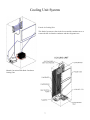
mabe
SERVICE MANUAL FOR SEDNA “ESTILO” REFRIGERATORS from Mabe
and G.E.
PUB # 06-MAN/RE-02
1
2
mabe
TABLE OF CONTENTS
OVERVIEW
FEATURES
Alarm, vacation mode, levels, turbo mode
TECHNICAL DATA
Electrical specifications, No-load operation, Cooling unit, Installation
AIRFLOW
Fan motors, baffle, lines
ICE FACTORY
Ice tray, filling ice buckets, ice disposal
ELECTRONIC CONTROL BOARDS
Deluxe electronic control card
Basic electronic control board
Control display board
DEFROST SYSTEM
3
OVERVIEW
The new no-frost refrigerator line called “IMAGINATION”, with 13, 15, 17 and 18
cubic foot capacity, is made in the refrigerator factory located in Queretaro,
Mexico.
The deluxe models (y) have basic electronic controls, while the deluxe models (z)
have display systems on the door. Some models include the QUICK FREEZER and
vacation mode button options for temperature control and defrost cycle.
Cooling unit: some models are designed with forced air cooling and have 2 fans,
one for the condenser and another one in the freezer for air circulation within the
refrigerator.
The new chamber for internal air distribution is equipped with the TURBO PLUS
COOLING SYSTEM that ensures the right temperature for each refrigerator
compartment.
DISCLAIMER
The information provided in this technical manual is designed for technical
personnel with knowledge and expertise in electricity, electronics and mechanics,
as a guide for servicing these automatic no-frost refrigerators. Any personal injuries
or property damages are the technical personnel's sole responsibility, for which
neither “MABE” nor “SERVIPLUS” will accept any liability based on the use of
this manual.
SAFETY
For your own safety, unplug the refrigerator from the electrical outlet before
servicing the appliance. If you need to test the appliance's power, amperage, etc.,
connect the appliance to the electric outlet only for the time required to make the
test.
The complete assembly of electronic boards and modules (elements) is very
sensitive to electric shock, and thus special procedures are required when handling
this material, like the use of ISOLATING STRIPS (IN WRISTBANDS, SHOES
OR GLOVES). YOU MUST NEVER TOUCH OR HANDLE THE BOARDS
IF YOU DO NOT HAVE THE PREVIOUSLY MENTIONED REQUIRED
EQUIPMENT.
4
FEATURES
A. Temperature Control Operation
The internal temperatures of the freezer and fresh food compartments can be regulated
individually to maintain better food conservation conditions, thus optimizing the use of
the appliance. These models feature controls for better temperature monitoring, one for the
freezer and one for the fresh food compartment.
The freezer control includes the maximum, medium and
minimum levels, to adjust the internal air-flow. The fresh
food compartment control allows temperature control from
level 1 (less cold) to 9 (coldest).
Fresh Food Compartment Temperature Control
To achieve the desired refrigeration you need to find the best
combination of temperatures for both the freezer and fresh
food compartment. Follow these instructions:
1) Start using your product keeping the factory preset
positions (medium level for both controls). Let the appliance
operate for 6 hours, so that the temperature becomes stable.
After this period, readjust the controls in case you need to
change the temperature.
2) The fresh food compartment control includes levels that
start at 1(less cold) to 9 (coldest). If necessary, adjust this
control and monitor the state of refrigerated items during a
few hours. In case you wish to adjust the control, you may
change it until you achieve the desired refrigeration level.
(Applicable in all models which do not have a Z in the
6th digit.)
3) The freezer control includes maximum, medium and
minimum levels. This refers to the amount of cold air that
will be sent to the refrigerator area. The lesser the air-flow in
the freezer, the quicker the fresh food compartment will
reach the desired temperature.
(Applicable in all models.)
5
Operating Instructions for the External Controls
Vacation Mode Directly enabled by pressing the button
(when enabled, the indicator light will turn on). It is disabled
by pressing the button or by opening the fresh food
compartment door for more than 10 seconds. You will also
see in the digital display an indicator light that swirls
quickly.
Turbo Mode Enabled and disabled pressing the button
(when enabled, the indicator light will turn on). You will
also see in the digital display an indicator light that swirls
quickly.
This feature remains enabled for approximately an hour.
Once this period is over, the refrigerator returns to normal
operation.
Alarm Enabled and disabled directly pressing the button
(when enabled, the indicator light will turn on).
Cooling Level If you press this button, the refrigerator's
cooling level can be increased from 1 to 9. Please see the
instructions for the fresh food compartment temperature
control in order to know how to select the appropriate
cooling level for your needs.
6
Cooling Unit System
Forced Air Cooling Unit
This kind of system uses fans in the freezer and the condenser area to
remove the hot air from the condenser and the refrigerator area.
Natural Convection With Static Condenser
Cooling Unit
7
CAPACITOR TO THERMAL PROTECTOR CONNECTION
THERMAL PROTECTOR
This component (installed in the compressor body) quickly detects any abnormal increase in temperature or excess
current caused by a failure of the electrical or mechanical system or an inappropriate application.
This compressor element consists of a bimetallic disc which, when it detects an excessive temperature in the
compressor or when its integrated resistance becomes too hot, due to an excessive current, bends and disconnects the
compressor, and the disc returns to normal electric contact when it cools off.
THERMAL PROTECTOR
RESISTANCE
BIMETALLIC DISC
In this refrigerator model, the Thermal Protector and the PTC (resistor) are installed in one box, which is connected at
the same time to the 2 elements in the compressor.
8
mabe
SAFETY
Before plugging the refrigerator into the electrical outlet, please make sure that:
All electrical connections are grounded and all wiring harnesses are connected, away from the sharp edges of the metal
plates, and that both the internal and external grounding connections of the appliance are properly connected.
ELECTRICAL SYSTEM
PTC (POSITIVE TEMPERATURE COEFFICIENT)
Unlike an electromechanical relay, the PTC resistor has no coil nor any moveable contacts. A PTC is a thermistor or,
in other words, a resistor sensitive to temperature, which can increase its resistance when the temperature is higher.
The operating element of the PTC is basically a highly pure barium titanate disc with aluminum coating.
When a certain voltage is transmitted to the PTC, at first a high current flows through it, raising its temperature and its
resistance. Due to the higher resistance, the current that feeds the starting coils of the compressor decreases
considerably.
This PTC property makes it possible for it to act as a substitute of the work carried out by the electromechanical relay
contacts.
PTC
BARIUM TITANATE DISC
CONTINUOUS LOAD (WORK) CAPACITOR
Some refrigerator models have an integrated 12 µf continuous load or work capacitor, at 200 A.C.V. (Alternating
Current Voltammetry), connected in a circuit parallel to the connections.
9
ELECTRICAL SPECIFICATIONS
Temperature Control (Level 5) ......................... ( )°F
Defrost Control ..................….............…...... 8, 10 AND12 hrs @ 35 min
Defrost Thermistor .............................................. °F
Voltage: 115V AC 60 Hz ................... Amp
Maximum Current Leakage ......................................... 0.75 mA
Maximum Grounding Step Resistance ..................... 0.14 Ohms
NO-LOAD OPERATION
MID/MID Control Position
Room Temperature: ........................................ 70°F
90°F
Fresh Food Compartment °F ....................................................
Freezer °F ....................................................
Compressor operation % ..........................
COOLING UNIT
Refrigerant charge (R134a) ................................... 3.5 ounce, 13 & 15 cubic foot models
Compressor cooling capacity, CB-E121 model .....................................
BTU/hr @ (3000 RPM)
Compressor minimum vacuum capacity ................................…............. 22 inches
Minimum equalized pressure
@70°F ....................................................................... 40 PSIG
@90°F ....................................................................... 54 PSIG
INSTALLATION
Minimum clearance required for air circulation:
ABOVE ........................................................................................ 1"
SIDES .............................................................................. 0.125"
BACK .................................................................................. 0.5"
AIR CIRCULATION
10
DEFROST CIRCUIT
The defrost circuit has a series of components that allows the disintegration of the frost formed during the cooling
cycle: control board, defrost sensor, relay number 2 in the board, output port in the board, defrost thermostat, fuses and
resistance (heater).
When the board processor has accumulated an amount of
compressor operating time and the sensor records a high
resistance value above 8.5 k., the board sends a 12 V. DC
signal to the relay and the relay connects to the resistance in
order to generate heat and melt all the accumulated frost.
FAN MOTORS
The cooling unit has two fan motors, one in the freezer compartment and another one in the condenser unit, which
operate at 127 volts AC.
The evaporator fan motor circulate the warmer air of the fresh food compartment through the evaporator and sends
cold air to the freezer and fresh food compartments.
The condenser fan motor works as an auxiliary dissipator of the heat generated by the condenser due to the cooling
vapor that circulates through the line.
11
If the heater is in circuit (on) for 20 minutes in the defrost cycle, the following cycle is increased
by 2 hours; if it is connected for 30 minutes, it is maintained as is; if it is connected for 40 minutes,
it is decreased by 2 hours. Thus, the defrost cycles are set within the minimum range of 8 hours,
maximum range of 12 hours, increasing or decreasing by 2 hours, and no changes are made from 8
to 12 hours or 12 to 8 hours.
If the refrigerator is operating and is disconnected for a short time or if there is an electrical power
failure, the board's stored memory relating to the time that the resistance was connected during the
last defrost cycle is lost. Thus, when the shut-off temperature indicated by the potentiometer and the
refrigerator's sensor is reached, the compressor is turned off and a defrost cycle is carried out, in
order to record the time that the resistance is connected and to program the next defrost cycle.
DEFROST SENSOR
The sensor's function is to detect the amount of ice and time that the resistance is enabled; in order
to vary the time when the next defrost cycle should be enabled.
DEFROST THERMOSTAT
The defrost thermostat consists of a one-pole switch, a bimetallic disc and a pressure bolt. These
items are installed inside a metallic cylinder filled with epoxy putty. The cylinder has two
connection cables, which are welded to the internal terminals of the cylinder.
If the defrost sensor does not disable the resistance's operation after 35 minutes maximum and the
thermostat's disconnection temperature is reached, the bimetallic disc is bent, disconnecting all
terminals with the pressure bolt. When the evaporator's temperature drops enough (depending on
the thermostat's specifications), the bimetallic disc recovers its shape and connects the terminals
again. Thus, the bimetallic disc acts as a safety device to avoid the temperature reaching more than
22 °C (71.6 ºF).
BIMETALLIC SAFETY
THERMOSTAT
12
Evaporator fan motor
Condenser fan motor assembly
13
For these models THERE ARE 2 DIFFERENT TYPES OF ELECTRONIC BOARD: ONE FOR
THE STANDARD AND DELUXE (“X”, “Y”) MODELS, which are models with BASIC ELECTRONICS
(see factsheet PTR05014), and ANOTHER ONE FOR SUPERDELUXE (Z) MODELS, which have an
EXTERNAL DISPLAY (see the following photos).
The different boards that have been used for the Polar, Polar Display and now Sedna models have
a different adjustment and/or setting. Thus, if you need to change any of them, you must request the
corresponding board for each model. The boards can be supplied as replacement parts, whose part number is
shown in the following table.
SUPERDELUXE BOARD VERSION (Z MODELS, WITH EXTERNAL DISPLAY)
(The Display Board (Door) is the same one used in POLAR WITH EXTERNAL DISPLAY models.)
200D5246G004 Main Board
for Sedna 16’& 18’Models
With External Display
CON3 with 4 pins.
Connect the External
Display here
3.- OPERATION CHECK. NORMAL CYCLE AND DEFROST CYCLE OPERATION.
A) DISASSEMBLE THE CONTROL BOARD AND REMOVE THE EVAPORATOR COVER.
B) DE-ENERGIZE THE APPLIANCE (UNPLUG IT FROM THE ELECTRICAL OUTLET).
C) DISCONNECT THE WIRING HARNESS FROM THE FREEZER SENSOR CON1.
D) ENERGIZE THE APPLIANCE (PLUG IT INTO THE ELECTRICAL OUTLET).
E) AFTER APROX. 4 SECONDS, TURN ON THE COMPRESSOR.
F) BRIDGE GND AND P_P (Test Point). THIS BRIDGE MUST REMAIN CONNECTED UNTIL
STEP (G) HAS BEEN COMPLETED.
G) THE COMPRESSOR WILL TURN OFF AFTER A MAXIMUM TIME OF 5 SECONDS AND 5
SECONDS LATER THE DEFROST RESISTANCE WILL START FUNCTIONING (As long as the
temperature in the evaporator is low enough to have the Defrost Thermostat closed and allow current
flow towards the Resistance).
H) BRIDGE THE CON1 PINS. THIS BRIDGE MUST REMAIN CONNECTED UNTIL STEP (I) HAS
BEEN COMPLETED.
I) THE DEFROST RESISTANCE MUST TURN OFF AFTER A MAXIMUM TIME OF 10 SECONDS.
J) DE-ENERGIZE THE APPLIANCE (UNPLUG IT FROM THE ELECTRICAL OUTLET).
K) CONNECT THE FREEZER SENSOR CON1.
L) ASSEMBLE THE CONTROL BOARD AND RE-PLACE THE EVAPORATOR COVER.
M) ENERGIZE THE APPLIANCE (PLUG IT INTO THE ELECTRICAL OUTLET).
14
BASIC ELECTRONIC BOARD VERSION (“X”& “Y” Models, with Knob)
200D5940G003 Basic
Electronic Main Board for
Sedna 13’& 15’ Models
200D5940G004 Basic
Electronic Main Board for
Sedna 17’& 19’ Models
These boards have a different
adjustment and cannot be
exchanged.
3.- OPERATION CHECK. DEFROST CYCLE OPERATION.
A) DISASSEMBLE THE CONTROL BOARD AND REMOVE THE EVAPORATOR COVER.
B) DE-ENERGIZE THE BOARD (UNPLUG THE BOARD-APPLIANCE WIRING HARNESS).
C) BRIDGE J2 AND J5. THIS BRIDGE MUST REMAIN CONNECTED UNTIL STEP (D) HAS BEEN
COMPLETED.
D) ENERGIZE THE BOARD (PLUG THE BOARD-APPLIANCE WIRING HARNESS).
E) THE DEFROST RESISTANCE SHOULD ACTIVATE (as long as the temperature in the evaporator is low
enough to have the Defrost Thermostat closed and allow current flow towards the Resistance).
F) TO RE-ENABLE THE COMPRESSOR OPERATION, FOLLOW THE INSTRUCTIONS FROM STEP
(G).
G) DE-ENERGIZE THE BOARD (UNPLUG THE BOARD-APPLIANCE WIRING HARNESS).
H) ENERGIZE THE BOARD (PLUG THE BOARD-APPLIANCE WIRING HARNESS). THIS
PROCEDURE MUST BE FOLLOWED WITHOUT HAVING THE J2 AND J5 BRIDGE
CONNECTED.
I) ASSEMBLE THE CONTROL BOARD AND RE-PLACE THE EVAPORATOR COVER.
15
DIRECT TEST FOR THE ELECTRONIC BOARD
REGULATED VOLTAGE TEST OF THE BOARD
The tests described here must be carried out with the sensor located in the fresh food
compartment and the potentiometer (temperature control) integrated to the board. In case any of
these components is damaged, the whole assembly must be changed because each board is
calibrated with these components.
When applying a 127 A.C.V. to the white and black cables, the board is energized. If these internal elements are
functioning properly, there will be a reading of 12 V.D.C. between test points GND and V12.
COMPRESSOR OPERATION
16
For these models THERE ARE 2 DIFFERENT TYPES OF ELECTRONIC BOARD: ONE FOR THE STANDARD
AND DELUXE (“X”, “Y”) MODELS, which are models with BASIC ELECTRONICS (see factsheet PTR05014),
and ANOTHER ONE FOR SUPERDELUXE (Z) MODELS (see factsheet PTR05014), which have an EXTERNAL
DISPLAY (see the following photos).
The different boards that have been used for the Polar, Polar Display and now Sedna models have a different
adjustment and/or setting. Thus, if you need to change any of them, you must request the corresponding board for each
model. The boards can be supplied as replacement parts, whose part number is shown in the following table.
PART NUMBER
DESCRIPTION
MODELS
200D2124G001
Main Board for 11’- 14’Models, 110 V
Polar, Electronic with knob
200D2124G002
Main Board for 11’- 14’Models, 220 V
Polar, Electronic with knob
200D2124G003
Main Board for 15’- 18’Models, 110 V
Polar, Electronic with knob
200D2124G004
Main Board for 15’- 18’Models, 220 V
Polar, Electronic with knob
200D4895G001
Main Board for 16’& 18’(Y) Models, 110 V
Polar, Internal Display
200D4896G001
Internal Display Board for 16’& 18’(Y) Models, 110 V
Polar, Internal Display
200D4894G001
Main Board for 12’& 18’(Z) Models, 110 V
Polar, Internal Display
200D4894G007
Main Board for 16’& 18’(Z) Models, 220 V
Polar, Internal Display
200D4897G001
External Display Board for 12’& 18’(Z) Models, 110/220 V
Polar, Internal Display
200D5246G004
Main Board for 16’& 18’(Z) Models, 110 V
Sedna with External Display
200D4897G001
External Display Board for 16’& 18’(Z) Models, 110 V
Sedna with External Display
200D5940G003
Main Board for 13’& 15’(X, Y) Models, 110 V
Sedna, Basic Electronics
200D5940G004
Main Board for 17’& 19’(X, Y) Models, 110 V
Sedna, Basic Electronics
17
When applying voltage to the white and black cables the board is energized and 10 seconds later it sends a signal to the
compressor to start working. You must now bridge test points GND and P.P., which will turn off the compressor. Three
seconds later, a signal will be sent to the defrost resistance to start working and, at this moment, the white and blue
cables must give a reading of 127 A.C.V.
NOTE: If the freezer sensor is connected and does not record the temperature, the board will not send the signal to the
heater to initiate the defrost cycle.
18
THERMISTOR TEST
Thermistors vary their resistance value according to the temperature they detect. For example, at
room temperature they have low resistance. When the temperature decreases, the resistance value
increases. The following table shows the approximate readings based on a temperature scale. In
fact, what is actually important about thermistors is that they must not show a reading of infinite
value (open) or zero resistance (closed), and when they turn hot or cold their resistance value
must vary.
Thermistors located in the freezer and in the fresh food compartment must have the same
characteristics and values; the difference stems from the type of connector and the temperature
they use to send a signal to the board.
TEMPERATURE
40 °C (104ºF)
35 °C (95ºF)
30 °C (86ºF)
25 °C (77ºF)
20 °C (68ºF)
15 °C (59ºF)
10 ° C (50ºF)
RESISTANCE
3,000 Ω
3, 500 Ω
4,100 Ω
5,000 Ω
6,000 Ω
7,800 Ω
9,300Ω
TEMPERATURE
5 ºC (41ºF)
0 ºC (32ºF)
-5 ºC (23ºF)
-10 ºC (14ºF)
-15 ºC (5ºF)
-20 ºC (-4ºF)
RESISTANCE
10,700 Ω
12,800 Ω
16,000 Ω
24,000 Ω
34,000 Ω
45,000Ω
NOTE: THE VALUES BETWEEN EACH READING CAN VARY, BECAUSE THE
THERMOMETER SENSES TEMPERATURE FASTER THAN THE THERMISTOR (SINCE
THE THERMISTOR IS ENCAPSULATED). IF THE THERMISTOR IS KEPT AT A
CONSTANT TEMPERATURE, THE RESISTANCE VALUE WILL BE HIGHER, BECAUSE
BOTH THE THERMOMETER AND THE THERMISTOR TEMPERATURE WILL BE
STABLE.
COMPRESSOR OPERATING CYCLE
When the electronic board sends a signal to enable the operating cycle of the compressor, both
the potentiometer and the temperature sensor start operating to precisely regulate compressor
operation and keep food at the desired temperature. When the potentiometer's knob is turned, this
indicates to the sensor the temperature range under which the fresh food compartment must be
kept and, at the same time, the sensor, based on this range, sends a signal to indicate the
compressor's periods of operation and idleness.
DEFROST CYCLE
When the refrigerator is connected for the first time or after a long period of not using it, the
electronic board will send a signal to enable the defrost cycle after eight hours of accumulated
compressor operating time, depending on the time the resistance keeps connected during the
defrost cycle (20, 30, 40 minutes).
19
SPECIAL FEATURES
SUPER COOLING FEATURE (QUICK COOLING)
When this function is selected, the LED2 light turns on, which indicates that a signal is being sent to the board. When
the shut-off temperature indicated by the thermistor and the potentiometer is reached, the board does not send the shutoff signal to the compressor, which continues operating non-stop for an hour. The LED light will turn off when the
compressor stops operating. The following diagram shows the additional operating time and how the temperature
decreases.
TEMPERATURE RECORD IN THE EVAPORATOR
VACATION MODE FEATURE
When this function is selected, the LED1 light turns on, which indicates that a signal is being sent to the board. The
defrost cycle will start according to the stored time in the board memory. The following defrost cycles will start after
48 hours of accumulated operating compressor time. This feature is cleared by the board's integrated photocell when
the fresh food compartment door is opened.
OPERATION TEST
Select the Vacation Mode feature, which will turn on the LED1 light. Close the hole located in the upper front part of
the air tower, on the fresh food compartment ceiling, to the right of the screw that holds the air tower. Wait a while and
then open the hole again, which will turn off the LED1 light, indicating that the feature is not operating anymore.
When the electronic board sends the signal to activate the operating cycle of the compressor, the potentiometer and
temperature sensor begin working to maintain food at the desired temperature. When the potentiometer knob is turned,
it indicates to the sensor the temperature range within which the fresh food compartment is to be kept. Based on this
range, the sensor then sends a signal to indicate the operation and rest periods of the compressor.
20
Evaporator cover assembly
Airflow system
Defrost system components are: the
thermostat, the thermistor and the
resistance (heater)
Defrost drainage system. The
defrost duct is hidden behind the
back and the insulating material.
Ice factory system
21
DIAGRAM
22
LIGHT BLUE
23
THE COMPRESOR USE IN SEDNA (ESTILO) REFRIGERATOR IS:
COMPRESSOR CBE121L2G DOE/FIDE FOR SEDNA 17´ Y 19´ THE SAME FORM FOR
POLAR 16¨AND 18´
IS 3.8 AMPERES.
Compressor CBZN100L2 PARA SEDNA 13´ Y 15´ THE SAME FORM FOR POLAR
12´ AND 14´ IS 3.8 AMPERES.
OPERATING PRESSURES: LOW SIDE AND HIGH SIDE :
De acuerdo al plano estos son los valores para el SEDNA
According to the Label these are the values for sedna (Estilo) is the following.
(Low Side) 0 , 97 Mpa
(High Side) 2, 31 MPa
High Side 335 PSI
Low side 140 PSI
24
PROBLEM
1 - The refrigerator does not
cool (the compressor and the
light bulb do not work).
FAILURE
No power in the contacts.
The wiring harness is disconnected or
making a false contact.
SOLUTION
Check contacts.
Connect pins or replace wiring harness.
2- The refrigerator does not
cool (the compressor does not
work, but the light bulb
works).
Potentiometer knob (temperature
control) in 0 position.
The electronic board does not send a
signal for the compressor to start
operating.
Refrigerator in defrost cycle.
Defective PTC.
Thermal protector with open circuit.
Wiring harness or connection with
open circuit.
Compressor (burned or forced).
Adjust the knob to a position other than 0.
3 - The refrigerator does not
cool (both the compressor and
the light bulb work).
4- The refrigerator does not
cool enough (the light bulb
works and the compressor
works too much).
5- Refrigerator (freezes food
in fresh food compartment),
excessive compressor
operation.
6- Excessive refrigerator
operation.
Leaking cooling unit.
Cooling unit with restriction.
The compressor does not compress.
Temperature control knob in low
position.
The electronic board does not send a
signal for the defrost cycle (the
evaporator is blocked with ice).
Defrost resistance has an open circuit
(evaporator blocked with ice).
Defrost thermostat with open circuit
(evaporator blocked with ice).
Short-circuit of defrost sensor (burned
or blocked).
Defective fan engine
Cooling unit has a leak.
Magnetic seal does not seal.
The door does not close well.
Defective light bulb switch (light bulb
on when door is closed).
Temperature control knob in high
position.
Temperature sensor in the incorrect
position.
Temperature control knob in high
position.
25
Check that the board is functioning
correctly.
Check the cycle and wait for it to end.
Replace PTC.
Replace thermal protector.
Check current continuity of connections
and wiring harness.
Check compressor and replace if
necessary.
Search for and repair leak.
Search for and repair restriction.
Change the compressor.
Move knob to higher position.
Check that the board is working correctly.
Change defrost resistance and melt ice.
Change defrost thermostat and melt ice.
Check or change wiring harness sensor.
Change fan engine.
Search for and repair leak.
Repair or change magnetic seal.
Adjust door.
Connect or change switch or adjust door
so that it switches light.
Adjust knob to a lower position.
Check correct position of sensor.
Adjust knob to a lower number position.